WO2021131585A1 - Système de détection de sons et dispositif de traitement d'informations - Google Patents
Système de détection de sons et dispositif de traitement d'informations Download PDFInfo
- Publication number
- WO2021131585A1 WO2021131585A1 PCT/JP2020/045125 JP2020045125W WO2021131585A1 WO 2021131585 A1 WO2021131585 A1 WO 2021131585A1 JP 2020045125 W JP2020045125 W JP 2020045125W WO 2021131585 A1 WO2021131585 A1 WO 2021131585A1
- Authority
- WO
- WIPO (PCT)
- Prior art keywords
- sound
- microphones
- detection system
- sound detection
- control unit
- Prior art date
Links
Images


Classifications
-
- A—HUMAN NECESSITIES
- A61—MEDICAL OR VETERINARY SCIENCE; HYGIENE
- A61B—DIAGNOSIS; SURGERY; IDENTIFICATION
- A61B7/00—Instruments for auscultation
- A61B7/02—Stethoscopes
- A61B7/04—Electric stethoscopes
-
- A—HUMAN NECESSITIES
- A61—MEDICAL OR VETERINARY SCIENCE; HYGIENE
- A61B—DIAGNOSIS; SURGERY; IDENTIFICATION
- A61B7/00—Instruments for auscultation
- A61B7/02—Stethoscopes
- A61B7/026—Stethoscopes comprising more than one sound collector
-
- H—ELECTRICITY
- H04—ELECTRIC COMMUNICATION TECHNIQUE
- H04R—LOUDSPEAKERS, MICROPHONES, GRAMOPHONE PICK-UPS OR LIKE ACOUSTIC ELECTROMECHANICAL TRANSDUCERS; DEAF-AID SETS; PUBLIC ADDRESS SYSTEMS
- H04R1/00—Details of transducers, loudspeakers or microphones
- H04R1/20—Arrangements for obtaining desired frequency or directional characteristics
- H04R1/32—Arrangements for obtaining desired frequency or directional characteristics for obtaining desired directional characteristic only
- H04R1/40—Arrangements for obtaining desired frequency or directional characteristics for obtaining desired directional characteristic only by combining a number of identical transducers
- H04R1/406—Arrangements for obtaining desired frequency or directional characteristics for obtaining desired directional characteristic only by combining a number of identical transducers microphones
-
- A—HUMAN NECESSITIES
- A61—MEDICAL OR VETERINARY SCIENCE; HYGIENE
- A61B—DIAGNOSIS; SURGERY; IDENTIFICATION
- A61B2562/00—Details of sensors; Constructional details of sensor housings or probes; Accessories for sensors
- A61B2562/02—Details of sensors specially adapted for in-vivo measurements
- A61B2562/0204—Acoustic sensors
-
- A—HUMAN NECESSITIES
- A61—MEDICAL OR VETERINARY SCIENCE; HYGIENE
- A61B—DIAGNOSIS; SURGERY; IDENTIFICATION
- A61B2562/00—Details of sensors; Constructional details of sensor housings or probes; Accessories for sensors
- A61B2562/04—Arrangements of multiple sensors of the same type
- A61B2562/046—Arrangements of multiple sensors of the same type in a matrix array
-
- H—ELECTRICITY
- H04—ELECTRIC COMMUNICATION TECHNIQUE
- H04R—LOUDSPEAKERS, MICROPHONES, GRAMOPHONE PICK-UPS OR LIKE ACOUSTIC ELECTROMECHANICAL TRANSDUCERS; DEAF-AID SETS; PUBLIC ADDRESS SYSTEMS
- H04R2201/00—Details of transducers, loudspeakers or microphones covered by H04R1/00 but not provided for in any of its subgroups
- H04R2201/40—Details of arrangements for obtaining desired directional characteristic by combining a number of identical transducers covered by H04R1/40 but not provided for in any of its subgroups
- H04R2201/401—2D or 3D arrays of transducers
-
- H—ELECTRICITY
- H04—ELECTRIC COMMUNICATION TECHNIQUE
- H04R—LOUDSPEAKERS, MICROPHONES, GRAMOPHONE PICK-UPS OR LIKE ACOUSTIC ELECTROMECHANICAL TRANSDUCERS; DEAF-AID SETS; PUBLIC ADDRESS SYSTEMS
- H04R3/00—Circuits for transducers, loudspeakers or microphones
- H04R3/005—Circuits for transducers, loudspeakers or microphones for combining the signals of two or more microphones
Definitions
- This disclosure relates to a sound detection system and an information processing device.
- auscultation of heart sounds is performed with a stethoscope or the like.
- Heart sounds include a sound called I sound and a sound called II sound.
- the I sound is the sound heard when the mitral valve and the tricuspid valve are closed.
- Sound II is the sound heard when the pulmonary and aortic valves close.
- Patent Document 1 detects a heart sound using a plurality of sensors, selects a specific sound such as a mitral valve closing sound from the detected heart sounds, and amplifies the selected specific sound.
- the technology is disclosed.
- a stenosis sound is generated immediately after the second sound. Detecting the sound of coronary artery stenosis is useful because it can detect signs of coronary artery disease such as angina pectoris and myocardial infarction.
- An object of the present disclosure is to provide a sound detection system and an information processing device capable of increasing the detection sensitivity for weak sounds inside a living body in view of the above problems.
- the sound detection system as the first aspect of the present disclosure includes a plurality of microphones capable of detecting the sound inside the living body and outputting a sound signal based on the detected sound, and an information processing device, and comprises the above-mentioned information processing.
- the device includes an acquisition unit, a control unit, and an output unit that acquire sound signals from the plurality of microphones, and the control unit includes a predetermined biological part based on the sound signals acquired by the acquisition unit.
- the first position which is the position of, is specified, the second position having a predetermined relative positional relationship with the first position is estimated, and the sensitivity to the second position is increased.
- the sound acquired by the acquisition unit while controlling the directivity of the plurality of microphones and controlling the directivity of the plurality of microphones so that the output unit has high sensitivity with respect to the second position. Outputs information based on the signal.
- the information processing device stores a storage unit that stores information on the predetermined relative positional relationship between the first position and the second position. Further prepare.
- control unit has the amplitude and phase of the sound signal acquired from each of the microphones with respect to the sound whose sound source is the predetermined biological part, and the plurality of microphones.
- the first position is specified based on the relative position.
- control unit controls the directivity of the plurality of microphones by adjusting and synthesizing the delay amount of the sound signal acquired from each of the microphones.
- control unit determines the intensity of the sound signal acquired from the second position, and causes the output unit to output an index based on the determination result.
- control unit controls the directivity of at least two of the plurality of microphones so as to be highly sensitive to the second position. ..
- control unit moves the positions of the plurality of microphones when the first position is separated from the positions of the plurality of microphones by a predetermined distance or more. Is output to the output unit.
- the relative positions of the plurality of microphones are fixed.
- the relative positions of the plurality of microphones are variable, and the sound detection system further includes a relative position measuring means for measuring the relative positions of the plurality of microphones.
- the control unit calculates the relative positions of the plurality of microphones based on the relative positions of the plurality of microphones measured by the relative position measuring means.
- the sound detection system as one embodiment of the present disclosure further includes an image pickup device, and in the sound detection system, the relative positions of the plurality of microphones are variable, and the control unit is the plurality of images captured by the image pickup device. The relative positions of the plurality of microphones are calculated based on the images of the microphones of.
- the information processing device as the second aspect of the present disclosure is a plurality of microphones capable of detecting sounds inside a living body and outputting sound signals based on the detected sounds, and acquisition of sound signals from the plurality of microphones.
- the control unit includes a unit, a control unit, and an output unit, and the control unit identifies a first position, which is a position of a predetermined biological part, based on the sound signal acquired by the acquisition unit, and the first position is described.
- a second position having a predetermined relative positional relationship with the position 1 is estimated, and the directivity of the plurality of microphones is controlled so that the sensitivity to the second position is high, and the output unit is used.
- the sound detection system and information processing device of the present disclosure it is possible to increase the detection sensitivity for weak sounds inside the living body.
- FIG. 1 is a functional block diagram of the sound detection system 1 according to the first embodiment of the present disclosure. The configuration and outline of the sound detection system 1 according to the first embodiment of the present disclosure will be described with reference to FIG.
- the sound detection system 1 includes a sound detection device 10, an information processing device 20, and an external sound detection microphone 30.
- the sound detection device 10 is a device that can be attached to a living body such as a human body to detect the sound inside the living body.
- the sound detection device 10 outputs a sound signal based on the detected sound inside the living body to the information processing device 20.
- the sound detection device 10 may be connected to the information processing device 20 by wire, or may be wirelessly connected to the information processing device 20 so as to be communicable.
- the sound detection device 10 includes a plurality of microphones 11-1 to 11-6 and a first coupling member 12. When it is not necessary to distinguish the microphones 11-1 to 11-6, they may be simply referred to as microphones 11. Although FIG. 1 shows six microphones 11-1 to 11-6, the number of microphones 11 is not limited to six. The number of microphones 11 may be any number of two or more.
- the microphone 11 can be attached to the surface of a living body such as a human body.
- the microphone 11 can detect the sound inside the living body while being attached to the surface of the living body.
- the microphone 11 may include, for example, a sticky sheet and can be attached to a living body by the sticky sheet.
- the method of attaching the microphone 11 to the living body is not limited to pasting.
- the microphone 11 may be attached to the living body by a method other than sticking.
- the microphone 11 outputs a sound signal based on the detected sound inside the living body to the information processing device 20.
- the microphone 11 may be connected to the information processing device 20 by wire. Further, the microphone 11 may have a wireless communication function. When having a wireless communication function, the microphone 11 may be connected to the information processing device 20 so as to be able to communicate wirelessly.
- the first coupling member 12 couples the plurality of microphones 11 so that the relative positions of the plurality of microphones 11 are fixed.
- the first coupling member 12 may be made of, for example, a highly rigid material so that the relative positions of the plurality of microphones 11 can be fixed.
- the first coupling member 12 couples the microphone 11-1 and the microphone 11-2. Further, the first coupling member 12 couples the microphone 11-3 and the microphone 11-4. Further, the first coupling member 12 couples the microphones 11-5 and the microphones 11-6. Further, the first coupling member 12 couples the microphone 11-1 and the microphone 11-3. Further, the first coupling member 12 couples the microphone 11-3 and the microphone 11-5. Further, the first coupling member 12 couples the microphone 11-2 and the microphone 11-4. Further, the first coupling member 12 couples the microphone 11-4 and the microphone 11-6.
- the sound detection device 10 is used by being attached to the surface of a living body in the vicinity where the sound to be detected is expected to be generated.
- the sound to be detected is a coronary artery stenosis sound
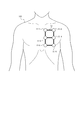
- the plurality of microphones 11-1 to 11-6 of the sound detection device 10 are attached near the heart of the human body.
- FIG. 2 shows an example of a case where a plurality of microphones 11-1 to 11-16 are attached near the heart of the human body 100.
- the information processing device 20 may be a dedicated computer used for the sound detection system 1 or a general-purpose computer.
- the information processing device 20 may be, for example, a tablet terminal, a smartphone, a notebook PC (Personal Computer), a desktop PC, or the like.
- the information processing device 20 acquires a sound signal based on the sound detected by the sound detection device 10 from the sound detection device 10. Further, the information processing device 20 acquires sound information based on the sound detected by the external sound detection microphone 30 from the external sound detection microphone 30.
- the information processing device 20 processes the sound signal acquired from the sound detection device 10 to increase the sensitivity to the weak sound to be detected.
- the configuration of the information processing device 20 will be described, and the details of the operation of the information processing device 20 will be described later.
- the information processing device 20 includes a communication unit 21, a storage unit 22, an acquisition unit 23, an input unit 24, an output unit 25, and a control unit 26.
- the communication unit 21 includes at least one communication interface.
- the communication interface is, for example, a LAN (Local Area Network) interface, a Bluetooth (registered trademark) interface, or the like.
- the communication unit 21 can communicate with various devices via a network or directly.
- the sound detection device 10 has a wireless communication function
- the communication unit 21 can wirelessly communicate with the sound detection device 10.
- the external sound detection microphone 30 has a wireless communication function
- the communication unit 21 can wirelessly communicate with the external sound detection microphone 30.
- the storage unit 22 is, for example, a semiconductor memory, a magnetic memory, an optical memory, or the like, but is not limited thereto.
- the storage unit 22 may function as, for example, a main storage device, an auxiliary storage device, or a cache memory.
- the storage unit 22 stores arbitrary information used for the operation of the information processing device 20.
- the storage unit 22 may store the system program, the application program, various information received by the communication unit 21, and the like.
- the information stored in the storage unit 22 may be updated with information received via, for example, the communication unit 21.
- a part of the storage unit 22 may be installed outside the information processing device 20. In that case, a part of the storage unit 22 installed outside may be connected to the information processing device 20 via an arbitrary interface.
- the acquisition unit 23 acquires a sound signal based on the sound detected by the sound detection device 10 from the sound detection device 10.
- the acquisition unit 23 may acquire a sound signal from the sound detection device 10 via the communication unit 21.
- the acquisition unit 23 acquires sound information based on the sound detected by the external sound detection microphone 30 from the external sound detection microphone 30.
- the acquisition unit 23 may acquire a sound signal from the external sound detection microphone 30 via the communication unit 21.
- the input unit 24 includes one or more input interfaces that detect user input and acquire input information based on the user's operation.
- the input unit 24 is, but is not limited to, a physical key, a capacitance key, a touch screen provided integrally with the display of the output unit 25, a microphone that accepts voice input, and the like.
- the output unit 25 includes one or more output interfaces that output information and notify the user.
- the output unit 25 includes, but is not limited to, a display that outputs information as a video, a speaker that outputs information as audio, and the like.
- the output unit 25 may be able to output information in various modes.
- the control unit 26 includes at least one processor, at least one dedicated circuit, or a combination thereof.
- the processor is a general-purpose processor such as a CPU (Central Processing Unit) or GPU (Graphics Processing Unit), or a dedicated processor specialized for a specific process.
- the dedicated circuit is, for example, FPGA (Field-Programmable Gate Array) or ASIC (Application Specific Integrated Circuit).
- the control unit 26 executes processing related to the operation of the information processing device 20 while controlling each unit of the information processing device 20.
- the external sound detection microphone 30 is a microphone capable of detecting an external sound.
- the "external sound” is a sound that becomes noise with respect to the sound detected by the sound detection device 10, such as the environmental sound around the sound detection system 1.
- the external sound detection microphone 30 outputs a sound signal based on the detected external sound to the information processing device 20.
- the external sound detection microphone 30 may be connected to the information processing device 20 by wire, or may be wirelessly connected to the information processing device 20 so as to be communicable.
- the sound detection system 1 can increase the detection sensitivity for weak sounds inside the living body.
- a case where a coronary artery stenosis sound is detected as a weak sound inside a living body will be described as a specific example.
- the user of the sound detection system 1 mounts the sound detection device 10 around a position where a weak sound to be detected is expected to be generated. For example, when the sound of coronary artery stenosis is the detection target, the user of the sound detection system 1 wears the sound detection device 10 near the heart of the human body.
- FIG. 2 is a diagram showing a state in which microphones 11-1 to 11-6 included in the sound detection device 10 are attached to the vicinity of the heart of the human body 100.
- Each of the microphones 11-1 to 11-6 outputs a sound signal based on the detected sound inside the human body to the information processing device 20.
- the acquisition unit 23 of the information processing device 20 acquires sound signals based on the sounds detected by the plurality of microphones 11-1 to 11-6 from the plurality of microphones 11-1 to 11-6.
- the acquisition unit 23 acquires a sound signal based on the external sound detected by the external sound detection microphone 30 from the external sound detection microphone 30.
- the control unit 26 of the information processing device 20 subtracts the sound signal acquired from the external sound detection microphone 30 from the sound signal acquired from the microphones 11-1 to 11-6 to cancel the noise.
- the sound detection system 1 can reduce noise components caused by external sounds included in the sound signals acquired from the microphones 11-1 to 11-6.
- the sound detection system 1 may not include the external sound detection microphone 30.
- the control unit 26 identifies the first position, which is the position of a predetermined biological part, based on the sound signal acquired by the acquisition unit 23.
- the sound signal acquired by the acquisition unit 23 may or may not be noise-canceled.
- the "first position” is a position of a biological part having a predetermined relative positional relationship with a position where a weak sound to be detected is expected to be generated.
- the position where a weak sound is expected to be generated is the position of the coronary artery.
- the position where a weak sound is expected to be generated is also referred to as a "second position".
- the predetermined biological part in the first position having a predetermined relative positional relationship with the second position is, for example, a mitral valve, a tricuspid valve, or a pulmonary valve. , And the aortic valve. Since the biological part at the first position is a biological part that generates a louder sound than the weak sound to be detected, the microphone 11 generates the sound generated at the first position at the second position. It can be detected more easily than the sound it makes.
- the storage unit 22 stores information on the relative positional relationship between the first position and the second position.
- the storage unit 22 stores information on the relative positional relationship between the first position and the second position for at least one first position.
- the first position is, for example, the position of the mitral valve, the position of the tricuspid valve, the position of the pulmonary valve, and the position of the aortic valve.
- the storage unit 22 has a relative positional relationship between the position of the mitral valve and the position of the coronary artery, a relative positional relationship between the position of the tricuspid valve and the position of the coronary artery, the position of the pulmonary valve and the position of the coronary artery. It stores the relative positional relationship with and at least one of the relative positional relationships between the position of the aortic valve and the position of the coronary artery.
- the I sound is the sound heard when the mitral valve and the tricuspid valve are closed.
- Sound II is the sound heard when the pulmonary and aortic valves close.
- the I sound is a superposition of the sound emitted when the mitral valve closes and the sound emitted when the tricuspid valve closes.
- the second sound is a sound obtained by superimposing the sound emitted when the pulmonary valve closes and the sound emitted when the aortic valve closes.
- the storage unit 22 stores the feature amount of the sound that the mitral valve closes, which is extracted based on the sample of the sound that is emitted when the mitral valve closes.
- the feature amount may include, for example, a spectral feature amount obtained by frequency analysis such as FFT (Fast Fourier Transform).
- the sample of the sound emitted when the mitral valve closes may be a sample obtained by measurement of the subject himself or herself, or may be a sample obtained by measurement of another measurer.
- the storage unit 22 stores the feature amount of the sound that the tricuspid valve closes, the feature amount of the sound that the pulmonary valve closes, and the feature amount of the sound that the aortic valve closes.
- the storage unit 22 stores the feature amount of the sound that the mitral valve closes, the feature amount of the sound that the tricuspid valve closes, the feature amount of the sound that the pulmonary valve closes, and the feature amount of the sound that the aortic valve closes. This is just an example, and the storage unit 22 stores a feature amount of an arbitrary sound that is expected to be emitted at the first position.
- the control unit 26 executes frequency analysis such as FFT on the sound signal acquired by the acquisition unit 23 from the sound detection device 10 and extracts the feature amount included in the sound signal.
- the control unit 26 compares the extracted feature amount with the feature amount of various samples stored in the storage unit 22, and specifies which sound the sound signal acquired by the acquisition unit 23 includes.
- the control unit 26 specifies, for example, that the sound signal acquired by the acquisition unit 23 includes the sound of the mitral valve closing and the sound of the tricuspid valve closing at the timing when the I sound is generated. For example, the control unit 26 identifies that the sound signal acquired by the acquisition unit 23 includes the sound of the pulmonary valve closing and the sound of the aortic valve closing at the timing when the II sound is generated.
- the control unit 26 When specifying the type of sound, the control unit 26 also specifies the first position, which is the position where the sound is generated. For example, when the control unit 26 identifies that the sound signal acquired by the acquisition unit 23 includes the sound of closing the mitral valve, the position where the sound of closing the mitral valve is generated, that is, the mitral valve. Identify the location of.
- the identification of the first position by the control unit 26 will be described with reference to FIGS. 3A and 3B. It is assumed that the waveforms shown in FIGS. 3A and 3B schematically show the sound signal generated at the first position.
- FIG. 3A is a sound signal detected by the microphone 11 mounted at a position close to the first position.
- FIG. 3B is a sound signal detected by the microphone 11 mounted at a position far from the first position. Looking at the sound signal of FIG. 3B, the amplitude is smaller and the phase is delayed as compared with the sound signal of FIG. 3A. Thus, the amplitude and phase of the sound signal depends on the distance from the first position. Therefore, if the relative positions of the plurality of microphones 11-1 to 11-6 are known, the amplitude and phase of the sound signal based on the sound detected by each microphone 11 and the relative positions of the plurality of microphones 11-1 to 11-6 are relative to each other. The first position can be specified based on the position.
- the relative positions of the plurality of microphones 11-1 to 11-6 are fixed, and the information on the relative positions of the plurality of microphones 11-1 to 11-6 is stored in the storage unit 22.
- the control unit 26 is based on the amplitude and phase of the sound signal acquired from each microphone 11 with respect to the sound whose sound source is a predetermined biological part, and the relative positions of the plurality of microphones 11-1 to 11-6. Specify the position of 1. For example, when a predetermined biological part is a mitral valve, the control unit 26 has a plurality of amplitudes and phases of sound signals acquired by the acquisition unit 23 from each microphone 11 with respect to the sound of the mitral valve as a sound source. The position of the mitral valve is specified based on the relative positions of the microphones 11-1 to 11-6.
- the control unit 26 similarly specifies the position of the tricuspid valve, the position of the pulmonary valve, and the position of the aortic valve.
- the control unit 26 does not need to specify all of the mitral valve position, the tricuspid valve position, the pulmonary valve position, and the aortic valve position as the first position.
- the control unit 26 may specify at least one of the position of the mitral valve, the position of the tricuspid valve, the position of the pulmonary valve, and the position of the aortic valve as the first position.
- the control unit 26 moves the positions of the plurality of microphones 11-1 to 11-6.
- the notification information recommended to be used may be output to the output unit 25.
- the control unit 26 sets the mounting locations of the plurality of microphones 11-1 to 11-6 so that the position near the center surrounded by the plurality of microphones 11-1 to 11-6 is near the first position.
- the information to be navigated may be output to the output unit 25.
- the control unit 26 When the control unit 26 specifies the first position, the control unit 26 estimates the second position based on the information of the relative positional relationship between the first position and the second position stored in the storage unit 22. To do. When the stenotic sound of the coronary artery is the detection target, the control unit 26 estimates the position of the coronary artery as the second position.
- FIG. 4 shows a schematic diagram in which the control unit 26 estimates the position of the coronary artery based on the position of the aortic valve and the position of the pulmonary valve.
- P1 is the position of the aortic valve specified by the control unit 26 based on the sound signal acquired by the acquisition unit 23.
- P2 is the position of the pulmonary valve identified by the control unit 26 based on the sound signal acquired by the acquisition unit 23.
- P3 is the position of the coronary artery estimated by the control unit 26 based on P1 and P2.
- the control unit 26 controls the directivity of the plurality of microphones 11-1 to 11-6 so that the sensitivity is higher with respect to the second position.
- the control unit 26 controls the directivity of the plurality of microphones 11-1 to 11-6 by, for example, adjusting and synthesizing the delay amount of the sound signals acquired from the microphones 11-1 to 11-6.
- the control unit 26 controls the directivity of the plurality of microphones 11-1 to 11-6 so as to have high sensitivity with respect to the second position, so that the sound signal generated at the second position has high sensitivity. Can be obtained.
- the control unit 26 does not have to use the sound signals of all the microphones 11-1 to 11-6 when controlling the directivity of the plurality of microphones 11-1 to 11-6.
- the control unit 26 may control the directivity of the microphone 11 by using the sound signals of at least two microphones 11 among the plurality of microphones 11-1 to 11-6.
- the output unit 25 outputs information based on the sound signal acquired by the acquisition unit 23 in a state where the directivity of the plurality of microphones 11-1 to 11-6 is controlled so as to increase the sensitivity with respect to the second position. To do.
- the output unit 25 may output information based on the sound signal acquired by the acquisition unit 23 in various modes.
- the output unit 25 may display, for example, a graph-like sound signal with the horizontal axis as the time axis and the vertical axis as the amplitude on the display. Further, the output unit 25 may output a sound signal as voice from the speaker, for example.
- the control unit 26 may determine the strength of the sound signal acquired from the second position and output an index based on the determination result to the output unit 25.
- the control unit 26 may determine, for example, whether or not the intensity of the sound signal acquired from the second position is equal to or higher than a predetermined threshold value. For example, when the intensity of the sound signal acquired from the second position is equal to or higher than a predetermined threshold value, the control unit 26 may display a display such as “there is a stenotic sound in the coronary artery” on the output unit 25. For example, the control unit 26 may compare the intensity of the sound signal acquired from the second position with a plurality of threshold values and determine it in multiple stages.
- control unit 26 calculates an index (referred to as “stenosis retention”) to the extent that stenosis is assumed based on the intensity of the stenosis sound of the coronary artery, and obtains “stenosis retention: 0.8”. Such a display may be displayed on the output unit 25.
- the control unit 26 may perform the determination process for the sound signal generated at the second position using the learning model learned by machine learning.
- the learning model may be, for example, a learning model learned based on the actual sound of coronary artery stenosis.
- the learning model may be stored in the storage unit 22.
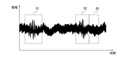
- FIGS. 5A to 5C show schematic views of how a weak sound signal, a stenotic sound of a coronary artery, is acquired with high sensitivity.
- FIG. 5A is a schematic diagram showing a sound signal before noise cancellation and directivity control of the microphone 11.
- FIG. 5B is a schematic diagram showing a sound signal at the stage of noise cancellation.
- FIG. 5C is a schematic diagram showing a sound signal at a stage where the directivity of the microphone 11 is controlled in addition to noise cancellation.
- the region indicated by R1 indicates the region where the I sound is detected.
- the region indicated by R2 indicates a region where the II sound is detected.
- R3 indicates the region where the stenotic sound of the coronary artery is detected.
- FIG. 5A it is difficult to determine whether or not a coronary artery stenosis sound is generated in R3.
- FIG. 5B due to the noise cancellation, a slight coronary artery stenosis sound is observed in R3, but it is still minute.
- FIG. 5C the control of the directivity of the microphone 11 emphasizes the coronary artery stenosis sound detected in R3.
- the operation of the sound detection system 1 will be described with reference to the flowchart shown in FIG.
- the operation shown in FIG. 6 is executed in a state where a plurality of microphones 11-1 to 11-6 of the sound detection device 10 are attached to the living body.
- the acquisition unit 23 of the information processing device 20 acquires sound signals from a plurality of microphones 11-1 to 11-6 (step S101).
- the control unit 26 of the information processing device 20 identifies the first position based on the sound signal acquired by the acquisition unit 23 in step S101 (step S102).
- the control unit 26 may specify the first position by using the sound signal after noise cancellation.
- the control unit 26 estimates the second position based on the first position specified in step S102 (step S103).
- the control unit 26 controls the directivity of the plurality of microphones 11-1 to 11-6 so as to have high sensitivity with respect to the second position estimated in step S103 (step S104).
- the control unit 26 outputs information based on the sound signal acquired by the acquisition unit 23 in a state where the directivity of the plurality of microphones 11-1 to 11-6 is controlled so as to increase the sensitivity with respect to the second position. It may be output to the unit 25.
- the acquisition unit 23 acquires sound signals based on the sounds inside the living body from the plurality of microphones 11-1 to 11-6.
- the control unit 26 identifies the first position, which is the position of a predetermined biological part, based on the sound signal acquired by the acquisition unit 23, and the second position has a predetermined relative positional relationship with the first position. The position is estimated, and the directivity of the plurality of microphones 11-1 to 11-6 is controlled so that the sensitivity to the second position is high.
- the output unit 25 receives information based on the sound signal acquired by the acquisition unit 23 in a state where the directivity of the plurality of microphones 11-1 to 11-6 is controlled so as to increase the sensitivity with respect to the second position. Is output.
- the sound detection system 1 according to the present embodiment can increase the detection sensitivity for weak sounds inside the living body.
- the sound detection system 1 enhances the detection sensitivity for the weak sound inside the living body, so that a weak sound such as a stenotic sound of a coronary artery can be produced by a plurality of microphones 11-1 to 11-. It can be detected by a simple measurement using 6.
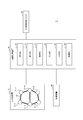
- FIG. 7 is a functional block diagram of the sound detection system 2 according to the second embodiment of the present disclosure.
- the sound detection system 2 includes a sound detection device 15, an information processing device 20, an external sound detection microphone 30, and an image pickup device 40.
- the differences from the sound detection system 1 according to the first embodiment will be mainly described, and the common points and similarities with the sound detection system 1 according to the first embodiment will be described. The points will not be described as appropriate.
- the sound detection device 15 includes a plurality of microphones 11-1 to 11-6 and a second coupling member 13. Although FIG. 7 shows six microphones 11-1 to 11-6, the number of microphones 11 is not limited to six. The number of microphones 11 may be any number of two or more.
- the second coupling member 13 couples the microphones 11-1 to 11-6 so that the relative positions of the plurality of microphones 11-1 to 11-6 are variable. Let me.
- the second connecting member 13 may be made of an elastic material such as rubber.
- the second coupling member 13 couples the microphone 11-1 and the microphone 11-2. Further, the second coupling member 13 couples the microphone 11-3 and the microphone 11-4. Further, the second coupling member 13 couples the microphones 11-5 and the microphones 11-6. Further, the second coupling member 13 couples the microphone 11-1 and the microphone 11-3. Further, the second coupling member 13 couples the microphone 11-3 and the microphone 11-5. Further, the second coupling member 13 couples the microphone 11-2 and the microphone 11-4. Further, the second coupling member 13 couples the microphone 11-4 and the microphone 11-6.
- FIG. 8 shows an example in which a plurality of microphones 11-1 to 11-16 are attached near the heart of the human body 100.
- the second coupling member 13 couples the microphones 11-1 to 11-6 so that the relative positions of the plurality of microphones 11-1 to 11-6 are variable. Therefore, a plurality of microphones 11-1 to 11-6 can be mounted at a desired position on the human body 100 with a high degree of freedom. The user can wear the plurality of microphones 11-1 to 11-6 while avoiding obstacles such as ribs.
- the image pickup device 40 can image a plurality of microphones 11-1 to 11-6 in a state of being attached to a living body. When the user captures a plurality of microphones 11-1 to 11-6, the image pickup device 40 outputs the captured image to the information processing device 20.
- the image pickup device 40 may be connected to the information processing device 20 by wire. Further, the image pickup device 40 may have a wireless communication function. When having a wireless communication function, the image pickup device 40 may wirelessly transmit the captured image to the information processing device 20.
- the acquisition unit 23 of the information processing device 20 acquires images of a plurality of microphones 11-1 to 11-6 captured by the image pickup device 40.
- the control unit 26 of the information processing device 20 analyzes the images of the plurality of microphones 11-1 to 11-6 acquired by the acquisition unit 23, and calculates the relative positions of the plurality of microphones 11-1 to 11-6. By using the calculated relative positions of the plurality of microphones 11-1 to 11-6, the control unit 26 determines the first position based on the sound signal acquired by the acquisition unit 23, as in the first embodiment. Can be identified.
- each component and each step can be rearranged so as not to be logically inconsistent, and a plurality of components or steps can be combined or divided into one. Is.
- the sound detection device 10 the information processing device 20, and the external sound detection microphone 30 are shown as separate devices, but the configuration is not limited to this.
- the sound detection device 10 may be incorporated in the information processing device 20.
- the external sound detection microphone 30 may be incorporated in the information processing device 20.
- the images of the plurality of microphones 11-1 to 11-6 captured by the image pickup apparatus 40 are analyzed, and the relative positions of the plurality of microphones 11-1 to 11-6 are calculated.
- the method of calculating the relative positions of the plurality of microphones 11-1 to 11-6 whose relative positions are variable is not limited to this.
- the sound detection system 2 according to the second embodiment may include a relative position measuring means capable of measuring the relative positions of the plurality of microphones 11-1 to 11-6, and the control unit 26 may include the relative position measuring means.
- the relative positions of the plurality of microphones 11-1 to 11-6 may be calculated based on the relative positions of the plurality of microphones 11-1 to 11-6 measured by.
- the relative position measuring means may include, for example, a strain sensor and an angle sensor.
- the strain sensor can measure the distance between the microphones 11.
- the angle sensor can also measure the angle between the microphones 11. Based on the measurement result of the strain sensor and the measurement result of the angle sensor, the control unit 26 may calculate the relative positions of the plurality of microphones 11-1 to 11-6.
- the relative position measuring means may include, for example, a magnetic field generator and magnetic sensors provided in a plurality of microphones 11-1 to 11-6. The magnetic sensor can measure the angle between the microphones 11. Based on the measurement result of this magnetic sensor, the control unit 26 may calculate the relative positions of the plurality of microphones 11-1 to 11-6.
- the sound detection device 15, the information processing device 20, the external sound detection microphone 30, and the image pickup device 40 are shown as separate devices, but the configuration is not limited to this.
- the sound detection device 15 may be incorporated in the information processing device 20.
- the external sound detection microphone 30 may be incorporated in the information processing device 20.
- the image pickup apparatus 40 may be incorporated in the information processing apparatus 20.
- the coronary artery stenosis sound is detected as a weak sound
- the weak sound to be detected is not limited to the coronary artery stenosis sound.
- the sound detection system 1 according to the first embodiment and the sound detection system 2 according to the second embodiment can also be applied to detect a weak sound other than the stenotic sound of the coronary artery.
- This disclosure relates to a sound detection system and an information processing device.
Abstract
L'invention concerne un système de détection de sons comprenant : une pluralité de microphones qui sont capables de détecter des sons à l'intérieur d'un corps vivant et qui sont capables de produire des signaux sonores sur la base des sons détectés ; et un dispositif de traitement d'informations. Le dispositif de traitement d'informations comprend : une unité d'acquisition qui acquiert les signaux sonores depuis la pluralité de microphones ; une unité de commande ; et une unité de sortie. L'unité de commande spécifie, sur la base des signaux sonores acquis par l'unité d'acquisition, une première position, qui est la position d'un site de corps vivant prescrit, estime une seconde position qui est dans une relation de position relative prescrite avec la première position, et commande les directivités de la pluralité de microphones de façon à augmenter la sensibilité par rapport à la seconde position. L'unité de sortie produit des informations qui sont basées sur des signaux sonores acquis par l'unité d'acquisition dans l'état dans lequel les directivités de la pluralité de microphones sont commandées de façon à augmenter la sensibilité par rapport à la seconde position.
Priority Applications (4)
| Application Number | Priority Date | Filing Date | Title |
|---|---|---|---|
| EP20907173.7A EP4079228B1 (fr) | 2019-12-27 | 2020-12-03 | Système de détection de sons et dispositif de traitement d'informations |
| CN202080090349.2A CN114845641A (zh) | 2019-12-27 | 2020-12-03 | 声音检测系统及信息处理装置 |
| JP2021567142A JPWO2021131585A1 (fr) | 2019-12-27 | 2020-12-03 | |
| US17/848,973 US20220354450A1 (en) | 2019-12-27 | 2022-06-24 | Sound detection system and information processing device |
Applications Claiming Priority (2)
| Application Number | Priority Date | Filing Date | Title |
|---|---|---|---|
| JP2019239343 | 2019-12-27 | ||
| JP2019-239343 | 2019-12-27 |
Related Child Applications (1)
| Application Number | Title | Priority Date | Filing Date |
|---|---|---|---|
| US17/848,973 Continuation US20220354450A1 (en) | 2019-12-27 | 2022-06-24 | Sound detection system and information processing device |
Publications (1)
| Publication Number | Publication Date |
|---|---|
| WO2021131585A1 true WO2021131585A1 (fr) | 2021-07-01 |
Family
ID=76573922
Family Applications (1)
| Application Number | Title | Priority Date | Filing Date |
|---|---|---|---|
| PCT/JP2020/045125 WO2021131585A1 (fr) | 2019-12-27 | 2020-12-03 | Système de détection de sons et dispositif de traitement d'informations |
Country Status (5)
| Country | Link |
|---|---|
| US (1) | US20220354450A1 (fr) |
| EP (1) | EP4079228B1 (fr) |
| JP (1) | JPWO2021131585A1 (fr) |
| CN (1) | CN114845641A (fr) |
| WO (1) | WO2021131585A1 (fr) |
Cited By (2)
| Publication number | Priority date | Publication date | Assignee | Title |
|---|---|---|---|---|
| WO2023189443A1 (fr) * | 2022-03-28 | 2023-10-05 | テルモ株式会社 | Dispositif de mesure de son biologique, procédé de mesure de son biologique et programme |
| WO2023239326A1 (fr) * | 2022-06-09 | 2023-12-14 | Bogazici Universitesi | Système et technique d'auscultation avec technique de réduction de bruit |
Citations (6)
| Publication number | Priority date | Publication date | Assignee | Title |
|---|---|---|---|---|
| JP2008528112A (ja) * | 2005-01-20 | 2008-07-31 | メッドスキャンソニックス・インコーポレイテッド | 冠状動脈内の異常の音響診断用装置 |
| JP2009188617A (ja) * | 2008-02-05 | 2009-08-20 | Yamaha Corp | 収音装置 |
| JP2011514199A (ja) * | 2008-03-04 | 2011-05-06 | コーニンクレッカ フィリップス エレクトロニクス エヌ ヴィ | 体の音の非侵襲的分析 |
| JP2015130904A (ja) * | 2014-01-09 | 2015-07-23 | 株式会社日立メディコ | 診察支援システム及び診察支援方法 |
| JP2018044774A (ja) * | 2016-09-12 | 2018-03-22 | マイクロコントロールシステムズ株式会社 | 振動発生体の状態を推定するシステム、装置、プログラム及び方法 |
| JP2019521756A (ja) * | 2016-06-15 | 2019-08-08 | シーヴイアール グローバル インコーポレイテッド | 流体流動血管内の閉塞を検出する方法 |
Family Cites Families (3)
| Publication number | Priority date | Publication date | Assignee | Title |
|---|---|---|---|---|
| US20110137209A1 (en) * | 2009-11-04 | 2011-06-09 | Lahiji Rosa R | Microphone arrays for listening to internal organs of the body |
| US8475396B2 (en) * | 2011-02-11 | 2013-07-02 | AventuSoft, LLC | Method and system of an acoustic scene analyzer for body sounds |
| US20170209115A1 (en) * | 2016-01-25 | 2017-07-27 | Quattro Folia Oy | Method and system of separating and locating a plurality of acoustic signal sources in a human body |
-
2020
- 2020-12-03 WO PCT/JP2020/045125 patent/WO2021131585A1/fr unknown
- 2020-12-03 CN CN202080090349.2A patent/CN114845641A/zh active Pending
- 2020-12-03 EP EP20907173.7A patent/EP4079228B1/fr active Active
- 2020-12-03 JP JP2021567142A patent/JPWO2021131585A1/ja active Pending
-
2022
- 2022-06-24 US US17/848,973 patent/US20220354450A1/en active Pending
Patent Citations (6)
| Publication number | Priority date | Publication date | Assignee | Title |
|---|---|---|---|---|
| JP2008528112A (ja) * | 2005-01-20 | 2008-07-31 | メッドスキャンソニックス・インコーポレイテッド | 冠状動脈内の異常の音響診断用装置 |
| JP2009188617A (ja) * | 2008-02-05 | 2009-08-20 | Yamaha Corp | 収音装置 |
| JP2011514199A (ja) * | 2008-03-04 | 2011-05-06 | コーニンクレッカ フィリップス エレクトロニクス エヌ ヴィ | 体の音の非侵襲的分析 |
| JP2015130904A (ja) * | 2014-01-09 | 2015-07-23 | 株式会社日立メディコ | 診察支援システム及び診察支援方法 |
| JP2019521756A (ja) * | 2016-06-15 | 2019-08-08 | シーヴイアール グローバル インコーポレイテッド | 流体流動血管内の閉塞を検出する方法 |
| JP2018044774A (ja) * | 2016-09-12 | 2018-03-22 | マイクロコントロールシステムズ株式会社 | 振動発生体の状態を推定するシステム、装置、プログラム及び方法 |
Non-Patent Citations (1)
| Title |
|---|
| See also references of EP4079228A4 * |
Cited By (2)
| Publication number | Priority date | Publication date | Assignee | Title |
|---|---|---|---|---|
| WO2023189443A1 (fr) * | 2022-03-28 | 2023-10-05 | テルモ株式会社 | Dispositif de mesure de son biologique, procédé de mesure de son biologique et programme |
| WO2023239326A1 (fr) * | 2022-06-09 | 2023-12-14 | Bogazici Universitesi | Système et technique d'auscultation avec technique de réduction de bruit |
Also Published As
| Publication number | Publication date |
|---|---|
| US20220354450A1 (en) | 2022-11-10 |
| CN114845641A (zh) | 2022-08-02 |
| EP4079228B1 (fr) | 2024-05-15 |
| EP4079228A1 (fr) | 2022-10-26 |
| EP4079228A4 (fr) | 2023-01-25 |
| JPWO2021131585A1 (fr) | 2021-07-01 |
Similar Documents
| Publication | Publication Date | Title |
|---|---|---|
| KR102070262B1 (ko) | 초음파 프로브 장치 및 그의 제어 방법 | |
| WO2021131585A1 (fr) | Système de détection de sons et dispositif de traitement d'informations | |
| CN101959462B (zh) | 身体声音的非侵入式分析 | |
| Fan et al. | HeadFi: bringing intelligence to all headphones | |
| WO2007034392A2 (fr) | Systeme d'imagerie par ultrasons comprenant des commandes activees vocalement au moyen d'un microphone distant | |
| US20100138191A1 (en) | Method and system for acquiring and transforming ultrasound data | |
| JP2010525646A (ja) | 音と位置の測定 | |
| US20220007964A1 (en) | Apparatus and method for detection of breathing abnormalities | |
| US9398899B2 (en) | Ultrasonic diagnostic apparatus and medical image processing apparatus | |
| JP2013172791A (ja) | 超音波検査装置、超音波検査方法、およびプログラム | |
| US20210186426A1 (en) | System and method for detection of middle ear fluids | |
| US20220192628A1 (en) | Contact-free acoustic monitoring and measurement system | |
| US20230283940A1 (en) | Smart headphone system and method | |
| CN102319062A (zh) | 用户参与血压值判断的血压测量方法 | |
| JP5528850B2 (ja) | 携帯端末装置、ストレス推定システム、動作方法、ストレス推定プログラム | |
| Levin et al. | Near-field signal acquisition for smartglasses using two acoustic vector-sensors | |
| JP2017207399A (ja) | 音源探査装置及び音源探査方法 | |
| JP5896832B2 (ja) | 検体情報処理装置及び検体情報処理方法 | |
| US20220280132A1 (en) | Medical device and program | |
| US20190216386A1 (en) | A fetal size monitoring system and method | |
| JP2019010436A (ja) | 生体センサおよび生体センサの信号取得方法 | |
| Yao et al. | Paris: passive and continuous fetal heart monitoring system | |
| US20230230582A1 (en) | Data augmentation system and method for multi-microphone systems | |
| US20230230580A1 (en) | Data augmentation system and method for multi-microphone systems | |
| US20140012095A1 (en) | Storage control apparatus, storage control system, and storage medium |
Legal Events
| Date | Code | Title | Description |
|---|---|---|---|
| 121 | Ep: the epo has been informed by wipo that ep was designated in this application |
Ref document number: 20907173 Country of ref document: EP Kind code of ref document: A1 |
|
| ENP | Entry into the national phase |
Ref document number: 2021567142 Country of ref document: JP Kind code of ref document: A |
|
| NENP | Non-entry into the national phase |
Ref country code: DE |
|
| ENP | Entry into the national phase |
Ref document number: 2020907173 Country of ref document: EP Effective date: 20220722 |