WO2021131585A1 - Sound detection system and information processing device - Google Patents
Sound detection system and information processing device Download PDFInfo
- Publication number
- WO2021131585A1 WO2021131585A1 PCT/JP2020/045125 JP2020045125W WO2021131585A1 WO 2021131585 A1 WO2021131585 A1 WO 2021131585A1 JP 2020045125 W JP2020045125 W JP 2020045125W WO 2021131585 A1 WO2021131585 A1 WO 2021131585A1
- Authority
- WO
- WIPO (PCT)
- Prior art keywords
- sound
- microphones
- detection system
- sound detection
- control unit
- Prior art date
Links
Images


Classifications
-
- A—HUMAN NECESSITIES
- A61—MEDICAL OR VETERINARY SCIENCE; HYGIENE
- A61B—DIAGNOSIS; SURGERY; IDENTIFICATION
- A61B7/00—Instruments for auscultation
- A61B7/02—Stethoscopes
- A61B7/04—Electric stethoscopes
-
- A—HUMAN NECESSITIES
- A61—MEDICAL OR VETERINARY SCIENCE; HYGIENE
- A61B—DIAGNOSIS; SURGERY; IDENTIFICATION
- A61B7/00—Instruments for auscultation
- A61B7/02—Stethoscopes
- A61B7/026—Stethoscopes comprising more than one sound collector
-
- H—ELECTRICITY
- H04—ELECTRIC COMMUNICATION TECHNIQUE
- H04R—LOUDSPEAKERS, MICROPHONES, GRAMOPHONE PICK-UPS OR LIKE ACOUSTIC ELECTROMECHANICAL TRANSDUCERS; DEAF-AID SETS; PUBLIC ADDRESS SYSTEMS
- H04R1/00—Details of transducers, loudspeakers or microphones
- H04R1/20—Arrangements for obtaining desired frequency or directional characteristics
- H04R1/32—Arrangements for obtaining desired frequency or directional characteristics for obtaining desired directional characteristic only
- H04R1/40—Arrangements for obtaining desired frequency or directional characteristics for obtaining desired directional characteristic only by combining a number of identical transducers
- H04R1/406—Arrangements for obtaining desired frequency or directional characteristics for obtaining desired directional characteristic only by combining a number of identical transducers microphones
-
- A—HUMAN NECESSITIES
- A61—MEDICAL OR VETERINARY SCIENCE; HYGIENE
- A61B—DIAGNOSIS; SURGERY; IDENTIFICATION
- A61B2562/00—Details of sensors; Constructional details of sensor housings or probes; Accessories for sensors
- A61B2562/02—Details of sensors specially adapted for in-vivo measurements
- A61B2562/0204—Acoustic sensors
-
- A—HUMAN NECESSITIES
- A61—MEDICAL OR VETERINARY SCIENCE; HYGIENE
- A61B—DIAGNOSIS; SURGERY; IDENTIFICATION
- A61B2562/00—Details of sensors; Constructional details of sensor housings or probes; Accessories for sensors
- A61B2562/04—Arrangements of multiple sensors of the same type
- A61B2562/046—Arrangements of multiple sensors of the same type in a matrix array
-
- H—ELECTRICITY
- H04—ELECTRIC COMMUNICATION TECHNIQUE
- H04R—LOUDSPEAKERS, MICROPHONES, GRAMOPHONE PICK-UPS OR LIKE ACOUSTIC ELECTROMECHANICAL TRANSDUCERS; DEAF-AID SETS; PUBLIC ADDRESS SYSTEMS
- H04R2201/00—Details of transducers, loudspeakers or microphones covered by H04R1/00 but not provided for in any of its subgroups
- H04R2201/40—Details of arrangements for obtaining desired directional characteristic by combining a number of identical transducers covered by H04R1/40 but not provided for in any of its subgroups
- H04R2201/401—2D or 3D arrays of transducers
-
- H—ELECTRICITY
- H04—ELECTRIC COMMUNICATION TECHNIQUE
- H04R—LOUDSPEAKERS, MICROPHONES, GRAMOPHONE PICK-UPS OR LIKE ACOUSTIC ELECTROMECHANICAL TRANSDUCERS; DEAF-AID SETS; PUBLIC ADDRESS SYSTEMS
- H04R3/00—Circuits for transducers, loudspeakers or microphones
- H04R3/005—Circuits for transducers, loudspeakers or microphones for combining the signals of two or more microphones
Definitions
- This disclosure relates to a sound detection system and an information processing device.
- auscultation of heart sounds is performed with a stethoscope or the like.
- Heart sounds include a sound called I sound and a sound called II sound.
- the I sound is the sound heard when the mitral valve and the tricuspid valve are closed.
- Sound II is the sound heard when the pulmonary and aortic valves close.
- Patent Document 1 detects a heart sound using a plurality of sensors, selects a specific sound such as a mitral valve closing sound from the detected heart sounds, and amplifies the selected specific sound.
- the technology is disclosed.
- a stenosis sound is generated immediately after the second sound. Detecting the sound of coronary artery stenosis is useful because it can detect signs of coronary artery disease such as angina pectoris and myocardial infarction.
- An object of the present disclosure is to provide a sound detection system and an information processing device capable of increasing the detection sensitivity for weak sounds inside a living body in view of the above problems.
- the sound detection system as the first aspect of the present disclosure includes a plurality of microphones capable of detecting the sound inside the living body and outputting a sound signal based on the detected sound, and an information processing device, and comprises the above-mentioned information processing.
- the device includes an acquisition unit, a control unit, and an output unit that acquire sound signals from the plurality of microphones, and the control unit includes a predetermined biological part based on the sound signals acquired by the acquisition unit.
- the first position which is the position of, is specified, the second position having a predetermined relative positional relationship with the first position is estimated, and the sensitivity to the second position is increased.
- the sound acquired by the acquisition unit while controlling the directivity of the plurality of microphones and controlling the directivity of the plurality of microphones so that the output unit has high sensitivity with respect to the second position. Outputs information based on the signal.
- the information processing device stores a storage unit that stores information on the predetermined relative positional relationship between the first position and the second position. Further prepare.
- control unit has the amplitude and phase of the sound signal acquired from each of the microphones with respect to the sound whose sound source is the predetermined biological part, and the plurality of microphones.
- the first position is specified based on the relative position.
- control unit controls the directivity of the plurality of microphones by adjusting and synthesizing the delay amount of the sound signal acquired from each of the microphones.
- control unit determines the intensity of the sound signal acquired from the second position, and causes the output unit to output an index based on the determination result.
- control unit controls the directivity of at least two of the plurality of microphones so as to be highly sensitive to the second position. ..
- control unit moves the positions of the plurality of microphones when the first position is separated from the positions of the plurality of microphones by a predetermined distance or more. Is output to the output unit.
- the relative positions of the plurality of microphones are fixed.
- the relative positions of the plurality of microphones are variable, and the sound detection system further includes a relative position measuring means for measuring the relative positions of the plurality of microphones.
- the control unit calculates the relative positions of the plurality of microphones based on the relative positions of the plurality of microphones measured by the relative position measuring means.
- the sound detection system as one embodiment of the present disclosure further includes an image pickup device, and in the sound detection system, the relative positions of the plurality of microphones are variable, and the control unit is the plurality of images captured by the image pickup device. The relative positions of the plurality of microphones are calculated based on the images of the microphones of.
- the information processing device as the second aspect of the present disclosure is a plurality of microphones capable of detecting sounds inside a living body and outputting sound signals based on the detected sounds, and acquisition of sound signals from the plurality of microphones.
- the control unit includes a unit, a control unit, and an output unit, and the control unit identifies a first position, which is a position of a predetermined biological part, based on the sound signal acquired by the acquisition unit, and the first position is described.
- a second position having a predetermined relative positional relationship with the position 1 is estimated, and the directivity of the plurality of microphones is controlled so that the sensitivity to the second position is high, and the output unit is used.
- the sound detection system and information processing device of the present disclosure it is possible to increase the detection sensitivity for weak sounds inside the living body.
- FIG. 1 is a functional block diagram of the sound detection system 1 according to the first embodiment of the present disclosure. The configuration and outline of the sound detection system 1 according to the first embodiment of the present disclosure will be described with reference to FIG.
- the sound detection system 1 includes a sound detection device 10, an information processing device 20, and an external sound detection microphone 30.
- the sound detection device 10 is a device that can be attached to a living body such as a human body to detect the sound inside the living body.
- the sound detection device 10 outputs a sound signal based on the detected sound inside the living body to the information processing device 20.
- the sound detection device 10 may be connected to the information processing device 20 by wire, or may be wirelessly connected to the information processing device 20 so as to be communicable.
- the sound detection device 10 includes a plurality of microphones 11-1 to 11-6 and a first coupling member 12. When it is not necessary to distinguish the microphones 11-1 to 11-6, they may be simply referred to as microphones 11. Although FIG. 1 shows six microphones 11-1 to 11-6, the number of microphones 11 is not limited to six. The number of microphones 11 may be any number of two or more.
- the microphone 11 can be attached to the surface of a living body such as a human body.
- the microphone 11 can detect the sound inside the living body while being attached to the surface of the living body.
- the microphone 11 may include, for example, a sticky sheet and can be attached to a living body by the sticky sheet.
- the method of attaching the microphone 11 to the living body is not limited to pasting.
- the microphone 11 may be attached to the living body by a method other than sticking.
- the microphone 11 outputs a sound signal based on the detected sound inside the living body to the information processing device 20.
- the microphone 11 may be connected to the information processing device 20 by wire. Further, the microphone 11 may have a wireless communication function. When having a wireless communication function, the microphone 11 may be connected to the information processing device 20 so as to be able to communicate wirelessly.
- the first coupling member 12 couples the plurality of microphones 11 so that the relative positions of the plurality of microphones 11 are fixed.
- the first coupling member 12 may be made of, for example, a highly rigid material so that the relative positions of the plurality of microphones 11 can be fixed.
- the first coupling member 12 couples the microphone 11-1 and the microphone 11-2. Further, the first coupling member 12 couples the microphone 11-3 and the microphone 11-4. Further, the first coupling member 12 couples the microphones 11-5 and the microphones 11-6. Further, the first coupling member 12 couples the microphone 11-1 and the microphone 11-3. Further, the first coupling member 12 couples the microphone 11-3 and the microphone 11-5. Further, the first coupling member 12 couples the microphone 11-2 and the microphone 11-4. Further, the first coupling member 12 couples the microphone 11-4 and the microphone 11-6.
- the sound detection device 10 is used by being attached to the surface of a living body in the vicinity where the sound to be detected is expected to be generated.
- the sound to be detected is a coronary artery stenosis sound
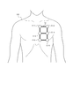
- the plurality of microphones 11-1 to 11-6 of the sound detection device 10 are attached near the heart of the human body.
- FIG. 2 shows an example of a case where a plurality of microphones 11-1 to 11-16 are attached near the heart of the human body 100.
- the information processing device 20 may be a dedicated computer used for the sound detection system 1 or a general-purpose computer.
- the information processing device 20 may be, for example, a tablet terminal, a smartphone, a notebook PC (Personal Computer), a desktop PC, or the like.
- the information processing device 20 acquires a sound signal based on the sound detected by the sound detection device 10 from the sound detection device 10. Further, the information processing device 20 acquires sound information based on the sound detected by the external sound detection microphone 30 from the external sound detection microphone 30.
- the information processing device 20 processes the sound signal acquired from the sound detection device 10 to increase the sensitivity to the weak sound to be detected.
- the configuration of the information processing device 20 will be described, and the details of the operation of the information processing device 20 will be described later.
- the information processing device 20 includes a communication unit 21, a storage unit 22, an acquisition unit 23, an input unit 24, an output unit 25, and a control unit 26.
- the communication unit 21 includes at least one communication interface.
- the communication interface is, for example, a LAN (Local Area Network) interface, a Bluetooth (registered trademark) interface, or the like.
- the communication unit 21 can communicate with various devices via a network or directly.
- the sound detection device 10 has a wireless communication function
- the communication unit 21 can wirelessly communicate with the sound detection device 10.
- the external sound detection microphone 30 has a wireless communication function
- the communication unit 21 can wirelessly communicate with the external sound detection microphone 30.
- the storage unit 22 is, for example, a semiconductor memory, a magnetic memory, an optical memory, or the like, but is not limited thereto.
- the storage unit 22 may function as, for example, a main storage device, an auxiliary storage device, or a cache memory.
- the storage unit 22 stores arbitrary information used for the operation of the information processing device 20.
- the storage unit 22 may store the system program, the application program, various information received by the communication unit 21, and the like.
- the information stored in the storage unit 22 may be updated with information received via, for example, the communication unit 21.
- a part of the storage unit 22 may be installed outside the information processing device 20. In that case, a part of the storage unit 22 installed outside may be connected to the information processing device 20 via an arbitrary interface.
- the acquisition unit 23 acquires a sound signal based on the sound detected by the sound detection device 10 from the sound detection device 10.
- the acquisition unit 23 may acquire a sound signal from the sound detection device 10 via the communication unit 21.
- the acquisition unit 23 acquires sound information based on the sound detected by the external sound detection microphone 30 from the external sound detection microphone 30.
- the acquisition unit 23 may acquire a sound signal from the external sound detection microphone 30 via the communication unit 21.
- the input unit 24 includes one or more input interfaces that detect user input and acquire input information based on the user's operation.
- the input unit 24 is, but is not limited to, a physical key, a capacitance key, a touch screen provided integrally with the display of the output unit 25, a microphone that accepts voice input, and the like.
- the output unit 25 includes one or more output interfaces that output information and notify the user.
- the output unit 25 includes, but is not limited to, a display that outputs information as a video, a speaker that outputs information as audio, and the like.
- the output unit 25 may be able to output information in various modes.
- the control unit 26 includes at least one processor, at least one dedicated circuit, or a combination thereof.
- the processor is a general-purpose processor such as a CPU (Central Processing Unit) or GPU (Graphics Processing Unit), or a dedicated processor specialized for a specific process.
- the dedicated circuit is, for example, FPGA (Field-Programmable Gate Array) or ASIC (Application Specific Integrated Circuit).
- the control unit 26 executes processing related to the operation of the information processing device 20 while controlling each unit of the information processing device 20.
- the external sound detection microphone 30 is a microphone capable of detecting an external sound.
- the "external sound” is a sound that becomes noise with respect to the sound detected by the sound detection device 10, such as the environmental sound around the sound detection system 1.
- the external sound detection microphone 30 outputs a sound signal based on the detected external sound to the information processing device 20.
- the external sound detection microphone 30 may be connected to the information processing device 20 by wire, or may be wirelessly connected to the information processing device 20 so as to be communicable.
- the sound detection system 1 can increase the detection sensitivity for weak sounds inside the living body.
- a case where a coronary artery stenosis sound is detected as a weak sound inside a living body will be described as a specific example.
- the user of the sound detection system 1 mounts the sound detection device 10 around a position where a weak sound to be detected is expected to be generated. For example, when the sound of coronary artery stenosis is the detection target, the user of the sound detection system 1 wears the sound detection device 10 near the heart of the human body.
- FIG. 2 is a diagram showing a state in which microphones 11-1 to 11-6 included in the sound detection device 10 are attached to the vicinity of the heart of the human body 100.
- Each of the microphones 11-1 to 11-6 outputs a sound signal based on the detected sound inside the human body to the information processing device 20.
- the acquisition unit 23 of the information processing device 20 acquires sound signals based on the sounds detected by the plurality of microphones 11-1 to 11-6 from the plurality of microphones 11-1 to 11-6.
- the acquisition unit 23 acquires a sound signal based on the external sound detected by the external sound detection microphone 30 from the external sound detection microphone 30.
- the control unit 26 of the information processing device 20 subtracts the sound signal acquired from the external sound detection microphone 30 from the sound signal acquired from the microphones 11-1 to 11-6 to cancel the noise.
- the sound detection system 1 can reduce noise components caused by external sounds included in the sound signals acquired from the microphones 11-1 to 11-6.
- the sound detection system 1 may not include the external sound detection microphone 30.
- the control unit 26 identifies the first position, which is the position of a predetermined biological part, based on the sound signal acquired by the acquisition unit 23.
- the sound signal acquired by the acquisition unit 23 may or may not be noise-canceled.
- the "first position” is a position of a biological part having a predetermined relative positional relationship with a position where a weak sound to be detected is expected to be generated.
- the position where a weak sound is expected to be generated is the position of the coronary artery.
- the position where a weak sound is expected to be generated is also referred to as a "second position".
- the predetermined biological part in the first position having a predetermined relative positional relationship with the second position is, for example, a mitral valve, a tricuspid valve, or a pulmonary valve. , And the aortic valve. Since the biological part at the first position is a biological part that generates a louder sound than the weak sound to be detected, the microphone 11 generates the sound generated at the first position at the second position. It can be detected more easily than the sound it makes.
- the storage unit 22 stores information on the relative positional relationship between the first position and the second position.
- the storage unit 22 stores information on the relative positional relationship between the first position and the second position for at least one first position.
- the first position is, for example, the position of the mitral valve, the position of the tricuspid valve, the position of the pulmonary valve, and the position of the aortic valve.
- the storage unit 22 has a relative positional relationship between the position of the mitral valve and the position of the coronary artery, a relative positional relationship between the position of the tricuspid valve and the position of the coronary artery, the position of the pulmonary valve and the position of the coronary artery. It stores the relative positional relationship with and at least one of the relative positional relationships between the position of the aortic valve and the position of the coronary artery.
- the I sound is the sound heard when the mitral valve and the tricuspid valve are closed.
- Sound II is the sound heard when the pulmonary and aortic valves close.
- the I sound is a superposition of the sound emitted when the mitral valve closes and the sound emitted when the tricuspid valve closes.
- the second sound is a sound obtained by superimposing the sound emitted when the pulmonary valve closes and the sound emitted when the aortic valve closes.
- the storage unit 22 stores the feature amount of the sound that the mitral valve closes, which is extracted based on the sample of the sound that is emitted when the mitral valve closes.
- the feature amount may include, for example, a spectral feature amount obtained by frequency analysis such as FFT (Fast Fourier Transform).
- the sample of the sound emitted when the mitral valve closes may be a sample obtained by measurement of the subject himself or herself, or may be a sample obtained by measurement of another measurer.
- the storage unit 22 stores the feature amount of the sound that the tricuspid valve closes, the feature amount of the sound that the pulmonary valve closes, and the feature amount of the sound that the aortic valve closes.
- the storage unit 22 stores the feature amount of the sound that the mitral valve closes, the feature amount of the sound that the tricuspid valve closes, the feature amount of the sound that the pulmonary valve closes, and the feature amount of the sound that the aortic valve closes. This is just an example, and the storage unit 22 stores a feature amount of an arbitrary sound that is expected to be emitted at the first position.
- the control unit 26 executes frequency analysis such as FFT on the sound signal acquired by the acquisition unit 23 from the sound detection device 10 and extracts the feature amount included in the sound signal.
- the control unit 26 compares the extracted feature amount with the feature amount of various samples stored in the storage unit 22, and specifies which sound the sound signal acquired by the acquisition unit 23 includes.
- the control unit 26 specifies, for example, that the sound signal acquired by the acquisition unit 23 includes the sound of the mitral valve closing and the sound of the tricuspid valve closing at the timing when the I sound is generated. For example, the control unit 26 identifies that the sound signal acquired by the acquisition unit 23 includes the sound of the pulmonary valve closing and the sound of the aortic valve closing at the timing when the II sound is generated.
- the control unit 26 When specifying the type of sound, the control unit 26 also specifies the first position, which is the position where the sound is generated. For example, when the control unit 26 identifies that the sound signal acquired by the acquisition unit 23 includes the sound of closing the mitral valve, the position where the sound of closing the mitral valve is generated, that is, the mitral valve. Identify the location of.
- the identification of the first position by the control unit 26 will be described with reference to FIGS. 3A and 3B. It is assumed that the waveforms shown in FIGS. 3A and 3B schematically show the sound signal generated at the first position.
- FIG. 3A is a sound signal detected by the microphone 11 mounted at a position close to the first position.
- FIG. 3B is a sound signal detected by the microphone 11 mounted at a position far from the first position. Looking at the sound signal of FIG. 3B, the amplitude is smaller and the phase is delayed as compared with the sound signal of FIG. 3A. Thus, the amplitude and phase of the sound signal depends on the distance from the first position. Therefore, if the relative positions of the plurality of microphones 11-1 to 11-6 are known, the amplitude and phase of the sound signal based on the sound detected by each microphone 11 and the relative positions of the plurality of microphones 11-1 to 11-6 are relative to each other. The first position can be specified based on the position.
- the relative positions of the plurality of microphones 11-1 to 11-6 are fixed, and the information on the relative positions of the plurality of microphones 11-1 to 11-6 is stored in the storage unit 22.
- the control unit 26 is based on the amplitude and phase of the sound signal acquired from each microphone 11 with respect to the sound whose sound source is a predetermined biological part, and the relative positions of the plurality of microphones 11-1 to 11-6. Specify the position of 1. For example, when a predetermined biological part is a mitral valve, the control unit 26 has a plurality of amplitudes and phases of sound signals acquired by the acquisition unit 23 from each microphone 11 with respect to the sound of the mitral valve as a sound source. The position of the mitral valve is specified based on the relative positions of the microphones 11-1 to 11-6.
- the control unit 26 similarly specifies the position of the tricuspid valve, the position of the pulmonary valve, and the position of the aortic valve.
- the control unit 26 does not need to specify all of the mitral valve position, the tricuspid valve position, the pulmonary valve position, and the aortic valve position as the first position.
- the control unit 26 may specify at least one of the position of the mitral valve, the position of the tricuspid valve, the position of the pulmonary valve, and the position of the aortic valve as the first position.
- the control unit 26 moves the positions of the plurality of microphones 11-1 to 11-6.
- the notification information recommended to be used may be output to the output unit 25.
- the control unit 26 sets the mounting locations of the plurality of microphones 11-1 to 11-6 so that the position near the center surrounded by the plurality of microphones 11-1 to 11-6 is near the first position.
- the information to be navigated may be output to the output unit 25.
- the control unit 26 When the control unit 26 specifies the first position, the control unit 26 estimates the second position based on the information of the relative positional relationship between the first position and the second position stored in the storage unit 22. To do. When the stenotic sound of the coronary artery is the detection target, the control unit 26 estimates the position of the coronary artery as the second position.
- FIG. 4 shows a schematic diagram in which the control unit 26 estimates the position of the coronary artery based on the position of the aortic valve and the position of the pulmonary valve.
- P1 is the position of the aortic valve specified by the control unit 26 based on the sound signal acquired by the acquisition unit 23.
- P2 is the position of the pulmonary valve identified by the control unit 26 based on the sound signal acquired by the acquisition unit 23.
- P3 is the position of the coronary artery estimated by the control unit 26 based on P1 and P2.
- the control unit 26 controls the directivity of the plurality of microphones 11-1 to 11-6 so that the sensitivity is higher with respect to the second position.
- the control unit 26 controls the directivity of the plurality of microphones 11-1 to 11-6 by, for example, adjusting and synthesizing the delay amount of the sound signals acquired from the microphones 11-1 to 11-6.
- the control unit 26 controls the directivity of the plurality of microphones 11-1 to 11-6 so as to have high sensitivity with respect to the second position, so that the sound signal generated at the second position has high sensitivity. Can be obtained.
- the control unit 26 does not have to use the sound signals of all the microphones 11-1 to 11-6 when controlling the directivity of the plurality of microphones 11-1 to 11-6.
- the control unit 26 may control the directivity of the microphone 11 by using the sound signals of at least two microphones 11 among the plurality of microphones 11-1 to 11-6.
- the output unit 25 outputs information based on the sound signal acquired by the acquisition unit 23 in a state where the directivity of the plurality of microphones 11-1 to 11-6 is controlled so as to increase the sensitivity with respect to the second position. To do.
- the output unit 25 may output information based on the sound signal acquired by the acquisition unit 23 in various modes.
- the output unit 25 may display, for example, a graph-like sound signal with the horizontal axis as the time axis and the vertical axis as the amplitude on the display. Further, the output unit 25 may output a sound signal as voice from the speaker, for example.
- the control unit 26 may determine the strength of the sound signal acquired from the second position and output an index based on the determination result to the output unit 25.
- the control unit 26 may determine, for example, whether or not the intensity of the sound signal acquired from the second position is equal to or higher than a predetermined threshold value. For example, when the intensity of the sound signal acquired from the second position is equal to or higher than a predetermined threshold value, the control unit 26 may display a display such as “there is a stenotic sound in the coronary artery” on the output unit 25. For example, the control unit 26 may compare the intensity of the sound signal acquired from the second position with a plurality of threshold values and determine it in multiple stages.
- control unit 26 calculates an index (referred to as “stenosis retention”) to the extent that stenosis is assumed based on the intensity of the stenosis sound of the coronary artery, and obtains “stenosis retention: 0.8”. Such a display may be displayed on the output unit 25.
- the control unit 26 may perform the determination process for the sound signal generated at the second position using the learning model learned by machine learning.
- the learning model may be, for example, a learning model learned based on the actual sound of coronary artery stenosis.
- the learning model may be stored in the storage unit 22.
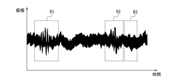
- FIGS. 5A to 5C show schematic views of how a weak sound signal, a stenotic sound of a coronary artery, is acquired with high sensitivity.
- FIG. 5A is a schematic diagram showing a sound signal before noise cancellation and directivity control of the microphone 11.
- FIG. 5B is a schematic diagram showing a sound signal at the stage of noise cancellation.
- FIG. 5C is a schematic diagram showing a sound signal at a stage where the directivity of the microphone 11 is controlled in addition to noise cancellation.
- the region indicated by R1 indicates the region where the I sound is detected.
- the region indicated by R2 indicates a region where the II sound is detected.
- R3 indicates the region where the stenotic sound of the coronary artery is detected.
- FIG. 5A it is difficult to determine whether or not a coronary artery stenosis sound is generated in R3.
- FIG. 5B due to the noise cancellation, a slight coronary artery stenosis sound is observed in R3, but it is still minute.
- FIG. 5C the control of the directivity of the microphone 11 emphasizes the coronary artery stenosis sound detected in R3.
- the operation of the sound detection system 1 will be described with reference to the flowchart shown in FIG.
- the operation shown in FIG. 6 is executed in a state where a plurality of microphones 11-1 to 11-6 of the sound detection device 10 are attached to the living body.
- the acquisition unit 23 of the information processing device 20 acquires sound signals from a plurality of microphones 11-1 to 11-6 (step S101).
- the control unit 26 of the information processing device 20 identifies the first position based on the sound signal acquired by the acquisition unit 23 in step S101 (step S102).
- the control unit 26 may specify the first position by using the sound signal after noise cancellation.
- the control unit 26 estimates the second position based on the first position specified in step S102 (step S103).
- the control unit 26 controls the directivity of the plurality of microphones 11-1 to 11-6 so as to have high sensitivity with respect to the second position estimated in step S103 (step S104).
- the control unit 26 outputs information based on the sound signal acquired by the acquisition unit 23 in a state where the directivity of the plurality of microphones 11-1 to 11-6 is controlled so as to increase the sensitivity with respect to the second position. It may be output to the unit 25.
- the acquisition unit 23 acquires sound signals based on the sounds inside the living body from the plurality of microphones 11-1 to 11-6.
- the control unit 26 identifies the first position, which is the position of a predetermined biological part, based on the sound signal acquired by the acquisition unit 23, and the second position has a predetermined relative positional relationship with the first position. The position is estimated, and the directivity of the plurality of microphones 11-1 to 11-6 is controlled so that the sensitivity to the second position is high.
- the output unit 25 receives information based on the sound signal acquired by the acquisition unit 23 in a state where the directivity of the plurality of microphones 11-1 to 11-6 is controlled so as to increase the sensitivity with respect to the second position. Is output.
- the sound detection system 1 according to the present embodiment can increase the detection sensitivity for weak sounds inside the living body.
- the sound detection system 1 enhances the detection sensitivity for the weak sound inside the living body, so that a weak sound such as a stenotic sound of a coronary artery can be produced by a plurality of microphones 11-1 to 11-. It can be detected by a simple measurement using 6.
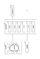
- FIG. 7 is a functional block diagram of the sound detection system 2 according to the second embodiment of the present disclosure.
- the sound detection system 2 includes a sound detection device 15, an information processing device 20, an external sound detection microphone 30, and an image pickup device 40.
- the differences from the sound detection system 1 according to the first embodiment will be mainly described, and the common points and similarities with the sound detection system 1 according to the first embodiment will be described. The points will not be described as appropriate.
- the sound detection device 15 includes a plurality of microphones 11-1 to 11-6 and a second coupling member 13. Although FIG. 7 shows six microphones 11-1 to 11-6, the number of microphones 11 is not limited to six. The number of microphones 11 may be any number of two or more.
- the second coupling member 13 couples the microphones 11-1 to 11-6 so that the relative positions of the plurality of microphones 11-1 to 11-6 are variable. Let me.
- the second connecting member 13 may be made of an elastic material such as rubber.
- the second coupling member 13 couples the microphone 11-1 and the microphone 11-2. Further, the second coupling member 13 couples the microphone 11-3 and the microphone 11-4. Further, the second coupling member 13 couples the microphones 11-5 and the microphones 11-6. Further, the second coupling member 13 couples the microphone 11-1 and the microphone 11-3. Further, the second coupling member 13 couples the microphone 11-3 and the microphone 11-5. Further, the second coupling member 13 couples the microphone 11-2 and the microphone 11-4. Further, the second coupling member 13 couples the microphone 11-4 and the microphone 11-6.
- FIG. 8 shows an example in which a plurality of microphones 11-1 to 11-16 are attached near the heart of the human body 100.
- the second coupling member 13 couples the microphones 11-1 to 11-6 so that the relative positions of the plurality of microphones 11-1 to 11-6 are variable. Therefore, a plurality of microphones 11-1 to 11-6 can be mounted at a desired position on the human body 100 with a high degree of freedom. The user can wear the plurality of microphones 11-1 to 11-6 while avoiding obstacles such as ribs.
- the image pickup device 40 can image a plurality of microphones 11-1 to 11-6 in a state of being attached to a living body. When the user captures a plurality of microphones 11-1 to 11-6, the image pickup device 40 outputs the captured image to the information processing device 20.
- the image pickup device 40 may be connected to the information processing device 20 by wire. Further, the image pickup device 40 may have a wireless communication function. When having a wireless communication function, the image pickup device 40 may wirelessly transmit the captured image to the information processing device 20.
- the acquisition unit 23 of the information processing device 20 acquires images of a plurality of microphones 11-1 to 11-6 captured by the image pickup device 40.
- the control unit 26 of the information processing device 20 analyzes the images of the plurality of microphones 11-1 to 11-6 acquired by the acquisition unit 23, and calculates the relative positions of the plurality of microphones 11-1 to 11-6. By using the calculated relative positions of the plurality of microphones 11-1 to 11-6, the control unit 26 determines the first position based on the sound signal acquired by the acquisition unit 23, as in the first embodiment. Can be identified.
- each component and each step can be rearranged so as not to be logically inconsistent, and a plurality of components or steps can be combined or divided into one. Is.
- the sound detection device 10 the information processing device 20, and the external sound detection microphone 30 are shown as separate devices, but the configuration is not limited to this.
- the sound detection device 10 may be incorporated in the information processing device 20.
- the external sound detection microphone 30 may be incorporated in the information processing device 20.
- the images of the plurality of microphones 11-1 to 11-6 captured by the image pickup apparatus 40 are analyzed, and the relative positions of the plurality of microphones 11-1 to 11-6 are calculated.
- the method of calculating the relative positions of the plurality of microphones 11-1 to 11-6 whose relative positions are variable is not limited to this.
- the sound detection system 2 according to the second embodiment may include a relative position measuring means capable of measuring the relative positions of the plurality of microphones 11-1 to 11-6, and the control unit 26 may include the relative position measuring means.
- the relative positions of the plurality of microphones 11-1 to 11-6 may be calculated based on the relative positions of the plurality of microphones 11-1 to 11-6 measured by.
- the relative position measuring means may include, for example, a strain sensor and an angle sensor.
- the strain sensor can measure the distance between the microphones 11.
- the angle sensor can also measure the angle between the microphones 11. Based on the measurement result of the strain sensor and the measurement result of the angle sensor, the control unit 26 may calculate the relative positions of the plurality of microphones 11-1 to 11-6.
- the relative position measuring means may include, for example, a magnetic field generator and magnetic sensors provided in a plurality of microphones 11-1 to 11-6. The magnetic sensor can measure the angle between the microphones 11. Based on the measurement result of this magnetic sensor, the control unit 26 may calculate the relative positions of the plurality of microphones 11-1 to 11-6.
- the sound detection device 15, the information processing device 20, the external sound detection microphone 30, and the image pickup device 40 are shown as separate devices, but the configuration is not limited to this.
- the sound detection device 15 may be incorporated in the information processing device 20.
- the external sound detection microphone 30 may be incorporated in the information processing device 20.
- the image pickup apparatus 40 may be incorporated in the information processing apparatus 20.
- the coronary artery stenosis sound is detected as a weak sound
- the weak sound to be detected is not limited to the coronary artery stenosis sound.
- the sound detection system 1 according to the first embodiment and the sound detection system 2 according to the second embodiment can also be applied to detect a weak sound other than the stenotic sound of the coronary artery.
- This disclosure relates to a sound detection system and an information processing device.
Abstract
Provided is a sound detection system including: a plurality of microphones that are capable of detecting sounds inside a living body and that are capable of outputting sound signals based on the detected sounds; and an information processing device. The information processing device includes: an acquisition unit that acquires the sound signals from the plurality of microphones; a control unit; and an output unit. The control unit specifies, on the basis of the sound signals acquired by the acquisition unit, a first position, which is the position of a prescribed living-body site, estimates a second position that is in a prescribed relative positional relationship with the first position, and controls the directivities of the plurality of microphones so as to increase the sensitivity with respect to the second position. The output unit outputs information that is based on sound signals acquired by the acquisition unit in the state in which the directivities of the plurality of microphones are controlled so as to increase the sensitivity with respect to the second position.
Description
本開示は、音検出システム及び情報処理装置に関する。
This disclosure relates to a sound detection system and an information processing device.
従来、患者の心臓の状態を診断するために、聴診器などによって心音を聴診することが行われている。
Conventionally, in order to diagnose the patient's heart condition, auscultation of heart sounds is performed with a stethoscope or the like.
心音には、I音と称される音、及びII音と称される音がある。I音は、僧帽弁及び三尖弁が閉じる時に聞こえる音である。II音は、肺動脈弁及び大動脈弁が閉じる時に聞こえる音である。
Heart sounds include a sound called I sound and a sound called II sound. The I sound is the sound heard when the mitral valve and the tricuspid valve are closed. Sound II is the sound heard when the pulmonary and aortic valves close.
例えば特許文献1は、複数のセンサを用いて心音を検出し、検出した心音のうちから、例えば僧帽弁が閉じる音のような特定の音を選択して、選択した特定の音を増幅する技術を開示している。
For example, Patent Document 1 detects a heart sound using a plurality of sensors, selects a specific sound such as a mitral valve closing sound from the detected heart sounds, and amplifies the selected specific sound. The technology is disclosed.
冠動脈に狭窄があると、II音の直後に狭窄音が発生する。冠動脈の狭窄音を検出することは、狭心症及び心筋梗塞のような冠動脈疾患の予兆を捉えることとなり有用である。
If there is a stenosis in the coronary artery, a stenosis sound is generated immediately after the second sound. Detecting the sound of coronary artery stenosis is useful because it can detect signs of coronary artery disease such as angina pectoris and myocardial infarction.
しかしながら、冠動脈の狭窄音は微弱な音であり、このような微弱な音を検出することが困難であった。
However, the sound of coronary artery stenosis is a faint sound, and it was difficult to detect such a faint sound.
本開示の目的は、上記問題に鑑み、生体の内部の微弱な音に対する検出感度を高めることができる音検出システム及び情報処理装置を提供することにある。
An object of the present disclosure is to provide a sound detection system and an information processing device capable of increasing the detection sensitivity for weak sounds inside a living body in view of the above problems.
本開示の第1の態様としての音検出システムは、生体の内部の音を検出し、検出した音に基づく音信号を出力可能な複数のマイクと、情報処理装置と、を備え、前記情報処理装置は、前記複数のマイクから音信号を取得する取得部と、制御部と、出力部と、を備え、前記制御部は、前記取得部が取得した前記音信号に基づいて、所定の生体部位の位置である第1の位置を特定し、前記第1の位置と所定の相対的な位置関係にある第2の位置を推定し、前記第2の位置に対して感度が高くなるように、前記複数のマイクの指向性を制御し、前記出力部は、前記第2の位置に対して感度が高くなるように前記複数のマイクの指向性が制御された状態で前記取得部が取得した音信号に基づく情報を出力する。
The sound detection system as the first aspect of the present disclosure includes a plurality of microphones capable of detecting the sound inside the living body and outputting a sound signal based on the detected sound, and an information processing device, and comprises the above-mentioned information processing. The device includes an acquisition unit, a control unit, and an output unit that acquire sound signals from the plurality of microphones, and the control unit includes a predetermined biological part based on the sound signals acquired by the acquisition unit. The first position, which is the position of, is specified, the second position having a predetermined relative positional relationship with the first position is estimated, and the sensitivity to the second position is increased. The sound acquired by the acquisition unit while controlling the directivity of the plurality of microphones and controlling the directivity of the plurality of microphones so that the output unit has high sensitivity with respect to the second position. Outputs information based on the signal.
本開示の一実施形態としての音検出システムにおいて、前記情報処理装置は、前記第1の位置と前記第2の位置との前記所定の相対的な位置関係の情報を格納している記憶部をさらに備える。
In the sound detection system as one embodiment of the present disclosure, the information processing device stores a storage unit that stores information on the predetermined relative positional relationship between the first position and the second position. Further prepare.
本開示の一実施形態としての音検出システムにおいて、前記制御部は、前記所定の生体部位を音源とする音に対して前記各マイクから取得した音信号の振幅及び位相と、前記複数のマイクの相対位置とに基づいて、前記第1の位置を特定する。
In the sound detection system as one embodiment of the present disclosure, the control unit has the amplitude and phase of the sound signal acquired from each of the microphones with respect to the sound whose sound source is the predetermined biological part, and the plurality of microphones. The first position is specified based on the relative position.
本開示の一実施形態としての音検出システムにおいて、前記制御部は、前記各マイクから取得した音信号の遅延量を調整して合成することにより、前記複数のマイクの指向性を制御する。
In the sound detection system as one embodiment of the present disclosure, the control unit controls the directivity of the plurality of microphones by adjusting and synthesizing the delay amount of the sound signal acquired from each of the microphones.
本開示の一実施形態としての音検出システムにおいて、前記制御部は、前記第2の位置から取得した音信号の強度を判定し、判定結果に基づく指標を前記出力部に出力させる。
In the sound detection system as one embodiment of the present disclosure, the control unit determines the intensity of the sound signal acquired from the second position, and causes the output unit to output an index based on the determination result.
本開示の一実施形態としての音検出システムにおいて、前記制御部は、前記第2の位置に対して感度が高くなるように、前記複数のマイクのうちの少なくとも2つのマイクの指向性を制御する。
In the sound detection system as one embodiment of the present disclosure, the control unit controls the directivity of at least two of the plurality of microphones so as to be highly sensitive to the second position. ..
本開示の一実施形態としての音検出システムにおいて、前記制御部は、前記第1の位置が前記複数のマイクの位置から所定の距離以上離れている場合、前記複数のマイクの位置を移動することを推奨する報知情報を前記出力部に出力させる。
In the sound detection system as one embodiment of the present disclosure, the control unit moves the positions of the plurality of microphones when the first position is separated from the positions of the plurality of microphones by a predetermined distance or more. Is output to the output unit.
本開示の一実施形態としての音検出システムにおいて、前記複数のマイクの相対位置は固定である。
In the sound detection system as one embodiment of the present disclosure, the relative positions of the plurality of microphones are fixed.
本開示の一実施形態としての音検出システムにおいて、前記複数のマイクの相対位置は可変であり、前記音検出システムは、前記複数のマイクのそれぞれの相対位置を測定する相対位置測定手段をさらに備え、前記制御部は、前記相対位置測定手段が測定した前記複数のマイクのそれぞれの相対位置に基づいて、前記複数のマイクの相対位置を算出する。
In the sound detection system as one embodiment of the present disclosure, the relative positions of the plurality of microphones are variable, and the sound detection system further includes a relative position measuring means for measuring the relative positions of the plurality of microphones. The control unit calculates the relative positions of the plurality of microphones based on the relative positions of the plurality of microphones measured by the relative position measuring means.
本開示の一実施形態としての音検出システムは、撮像装置をさらに備え、前記音検出システムにおいて、前記複数のマイクの相対位置は可変であり、前記制御部は、前記撮像装置が撮像した前記複数のマイクの画像に基づいて、前記複数のマイクの相対位置を算出する。
The sound detection system as one embodiment of the present disclosure further includes an image pickup device, and in the sound detection system, the relative positions of the plurality of microphones are variable, and the control unit is the plurality of images captured by the image pickup device. The relative positions of the plurality of microphones are calculated based on the images of the microphones of.
本開示の第2の態様としての情報処理装置は、生体の内部の音を検出し、検出した音に基づく音信号を出力可能な複数のマイクと、前記複数のマイクから音信号を取得する取得部と、制御部と、出力部と、を備え、前記制御部は、前記取得部が取得した前記音信号に基づいて、所定の生体部位の位置である第1の位置を特定し、前記第1の位置と所定の相対的な位置関係にある第2の位置を推定し、前記第2の位置に対して感度が高くなるように、前記複数のマイクの指向性を制御し、前記出力部は、前記第2の位置に対して感度が高くなるように前記複数のマイクの指向性が制御された状態で前記取得部が取得した音信号に基づく情報を出力する。
The information processing device as the second aspect of the present disclosure is a plurality of microphones capable of detecting sounds inside a living body and outputting sound signals based on the detected sounds, and acquisition of sound signals from the plurality of microphones. The control unit includes a unit, a control unit, and an output unit, and the control unit identifies a first position, which is a position of a predetermined biological part, based on the sound signal acquired by the acquisition unit, and the first position is described. A second position having a predetermined relative positional relationship with the position 1 is estimated, and the directivity of the plurality of microphones is controlled so that the sensitivity to the second position is high, and the output unit is used. Outputs information based on the sound signal acquired by the acquisition unit in a state where the directivity of the plurality of microphones is controlled so as to increase the sensitivity with respect to the second position.
本開示の音検出システム及び情報処理装置によると、生体の内部の微弱な音に対する検出感度を高めることができる。
According to the sound detection system and information processing device of the present disclosure, it is possible to increase the detection sensitivity for weak sounds inside the living body.
以下、本開示の実施形態について、図面を参照して説明する。各図において共通の構成部には、同一の符号を付している。
Hereinafter, embodiments of the present disclosure will be described with reference to the drawings. The same reference numerals are given to the common components in each figure.
(第1実施形態)
図1は、本開示の第1実施形態に係る音検出システム1の機能ブロック図である。図1を参照して、本開示の第1実施形態に係る音検出システム1の構成及び概要を説明する。 (First Embodiment)
FIG. 1 is a functional block diagram of the sound detection system 1 according to the first embodiment of the present disclosure. The configuration and outline of the sound detection system 1 according to the first embodiment of the present disclosure will be described with reference to FIG.
音検出システム1は、音検出装置10と、情報処理装置20と、外部音検出マイク30とを備える。
The sound detection system 1 includes a sound detection device 10, an information processing device 20, and an external sound detection microphone 30.
音検出装置10は、人体などの生体に装着されて生体の内部の音を検出することが可能な装置である。音検出装置10は、検出した生体の内部の音に基づく音信号を情報処理装置20に出力する。音検出装置10は、情報処理装置20と有線で接続されていてもよいし、情報処理装置20と無線で通信可能に接続されていてもよい。
The sound detection device 10 is a device that can be attached to a living body such as a human body to detect the sound inside the living body. The sound detection device 10 outputs a sound signal based on the detected sound inside the living body to the information processing device 20. The sound detection device 10 may be connected to the information processing device 20 by wire, or may be wirelessly connected to the information processing device 20 so as to be communicable.
音検出装置10は、複数のマイク11-1~11-6と、第1結合部材12とを備える。マイク11-1~11-6について特に区別する必要がない場合、以後、単にマイク11と称する場合がある。図1においては、6個のマイク11-1~11-6を示しているが、マイク11の個数は6個に限定されない。マイク11は2個以上の任意の個数であってよい。
The sound detection device 10 includes a plurality of microphones 11-1 to 11-6 and a first coupling member 12. When it is not necessary to distinguish the microphones 11-1 to 11-6, they may be simply referred to as microphones 11. Although FIG. 1 shows six microphones 11-1 to 11-6, the number of microphones 11 is not limited to six. The number of microphones 11 may be any number of two or more.
マイク11は、人体などの生体の表面に装着可能である。マイク11は、生体の表面に装着された状態で、生体の内部の音を検出可能である。マイク11は、例えば、粘着性を有するシートを備え、粘着性を有するシートによって生体に貼り付け可能であってよい。マイク11を生体へ装着させる方法は、貼り付けに限定されない。マイク11は、貼り付け以外の方法で、生体に装着されてよい。
The microphone 11 can be attached to the surface of a living body such as a human body. The microphone 11 can detect the sound inside the living body while being attached to the surface of the living body. The microphone 11 may include, for example, a sticky sheet and can be attached to a living body by the sticky sheet. The method of attaching the microphone 11 to the living body is not limited to pasting. The microphone 11 may be attached to the living body by a method other than sticking.
マイク11は、検出した生体の内部の音に基づく音信号を情報処理装置20に出力する。マイク11は、情報処理装置20と有線で接続されていてよい。また、マイク11は、無線通信機能を有してもよい。無線通信機能を有する場合、マイク11は、情報処理装置20と無線で通信可能に接続されていてもよい。
The microphone 11 outputs a sound signal based on the detected sound inside the living body to the information processing device 20. The microphone 11 may be connected to the information processing device 20 by wire. Further, the microphone 11 may have a wireless communication function. When having a wireless communication function, the microphone 11 may be connected to the information processing device 20 so as to be able to communicate wirelessly.
第1結合部材12は、複数のマイク11の相対位置が固定となるように、複数のマイク11を結合させる。第1結合部材12は、複数のマイク11の相対位置を固定できるように、例えば剛性の高い材料で構成されていてよい。
The first coupling member 12 couples the plurality of microphones 11 so that the relative positions of the plurality of microphones 11 are fixed. The first coupling member 12 may be made of, for example, a highly rigid material so that the relative positions of the plurality of microphones 11 can be fixed.
図1に示す例においては、第1結合部材12は、マイク11-1とマイク11-2とを結合させる。また、第1結合部材12は、マイク11-3とマイク11-4とを結合させる。また、第1結合部材12は、マイク11-5とマイク11-6とを結合させる。また、第1結合部材12は、マイク11-1とマイク11-3とを結合させる。また、第1結合部材12は、マイク11-3とマイク11-5とを結合させる。また、第1結合部材12は、マイク11-2とマイク11-4とを結合させる。また、第1結合部材12は、マイク11-4とマイク11-6とを結合させる。
In the example shown in FIG. 1, the first coupling member 12 couples the microphone 11-1 and the microphone 11-2. Further, the first coupling member 12 couples the microphone 11-3 and the microphone 11-4. Further, the first coupling member 12 couples the microphones 11-5 and the microphones 11-6. Further, the first coupling member 12 couples the microphone 11-1 and the microphone 11-3. Further, the first coupling member 12 couples the microphone 11-3 and the microphone 11-5. Further, the first coupling member 12 couples the microphone 11-2 and the microphone 11-4. Further, the first coupling member 12 couples the microphone 11-4 and the microphone 11-6.
音検出装置10は、検出対象の音が発生することが想定される付近において、生体の表面に装着して用いられる。本実施形態においては、検出対象の音が冠動脈の狭窄音である場合を例に挙げて説明する。この場合、音検出装置10の複数のマイク11-1~11-6は、人体の心臓付近に装着される。図2に、複数のマイク11-1~11-16が、人体100の心臓付近に装着されている場合の一例を示す。
The sound detection device 10 is used by being attached to the surface of a living body in the vicinity where the sound to be detected is expected to be generated. In the present embodiment, a case where the sound to be detected is a coronary artery stenosis sound will be described as an example. In this case, the plurality of microphones 11-1 to 11-6 of the sound detection device 10 are attached near the heart of the human body. FIG. 2 shows an example of a case where a plurality of microphones 11-1 to 11-16 are attached near the heart of the human body 100.
情報処理装置20は、音検出システム1に用いられる専用のコンピュータであってもよいし、汎用のコンピュータであってもよい。汎用のコンピュータである場合、情報処理装置20は、例えば、タブレット端末、スマートフォン、ノートPC(Personal Computer)、又はデスクトップPCなどであってよい。
The information processing device 20 may be a dedicated computer used for the sound detection system 1 or a general-purpose computer. In the case of a general-purpose computer, the information processing device 20 may be, for example, a tablet terminal, a smartphone, a notebook PC (Personal Computer), a desktop PC, or the like.
情報処理装置20は、音検出装置10から、音検出装置10が検出した音に基づく音信号を取得する。また、情報処理装置20は、外部音検出マイク30から、外部音検出マイク30が検出した音に基づく音情報を取得する。
The information processing device 20 acquires a sound signal based on the sound detected by the sound detection device 10 from the sound detection device 10. Further, the information processing device 20 acquires sound information based on the sound detected by the external sound detection microphone 30 from the external sound detection microphone 30.
情報処理装置20は、音検出装置10から取得した音信号を処理し、検出対象である微弱な音に対する感度を高める。以後、情報処理装置20の構成について説明し、情報処理装置20の動作の詳細については後述する。
The information processing device 20 processes the sound signal acquired from the sound detection device 10 to increase the sensitivity to the weak sound to be detected. Hereinafter, the configuration of the information processing device 20 will be described, and the details of the operation of the information processing device 20 will be described later.
情報処理装置20は、通信部21と、記憶部22と、取得部23と、入力部24と、出力部25と、制御部26とを備える。
The information processing device 20 includes a communication unit 21, a storage unit 22, an acquisition unit 23, an input unit 24, an output unit 25, and a control unit 26.
通信部21は、少なくとも1つの通信用インタフェースを含む。通信用インタフェースは、例えば、LAN(Local Area Network)インタフェース、又はBluetooth(登録商標)インタフェースなどである。通信部21は、ネットワークを介して又は直接、各種装置と通信可能である。音検出装置10が無線通信機能を有する場合、通信部21は、音検出装置10と無線通信可能である。外部音検出マイク30が無線通信機能を有する場合、通信部21は、外部音検出マイク30と無線通信可能である。
The communication unit 21 includes at least one communication interface. The communication interface is, for example, a LAN (Local Area Network) interface, a Bluetooth (registered trademark) interface, or the like. The communication unit 21 can communicate with various devices via a network or directly. When the sound detection device 10 has a wireless communication function, the communication unit 21 can wirelessly communicate with the sound detection device 10. When the external sound detection microphone 30 has a wireless communication function, the communication unit 21 can wirelessly communicate with the external sound detection microphone 30.
記憶部22は、例えば半導体メモリ、磁気メモリ、又は光メモリ等であるが、これらに限定されない。記憶部22は、例えば主記憶装置、補助記憶装置、又はキャッシュメモリとして機能してもよい。記憶部22は、情報処理装置20の動作に用いられる任意の情報を記憶する。例えば、記憶部22は、システムプログラム、アプリケーションプログラム、及び通信部21によって受信された各種情報等を記憶してもよい。記憶部22に記憶された情報は、例えば通信部21を介して受信される情報で更新可能であってもよい。記憶部22の一部は、情報処理装置20の外部に設置されていてもよい。その場合、外部に設置されている記憶部22の一部は、任意のインタフェースを介して情報処理装置20と接続されてよい。
The storage unit 22 is, for example, a semiconductor memory, a magnetic memory, an optical memory, or the like, but is not limited thereto. The storage unit 22 may function as, for example, a main storage device, an auxiliary storage device, or a cache memory. The storage unit 22 stores arbitrary information used for the operation of the information processing device 20. For example, the storage unit 22 may store the system program, the application program, various information received by the communication unit 21, and the like. The information stored in the storage unit 22 may be updated with information received via, for example, the communication unit 21. A part of the storage unit 22 may be installed outside the information processing device 20. In that case, a part of the storage unit 22 installed outside may be connected to the information processing device 20 via an arbitrary interface.
取得部23は、音検出装置10から、音検出装置10が検出した音に基づく音信号を取得する。取得部23は、通信部21を介して、音検出装置10から音信号を取得してもよい。
The acquisition unit 23 acquires a sound signal based on the sound detected by the sound detection device 10 from the sound detection device 10. The acquisition unit 23 may acquire a sound signal from the sound detection device 10 via the communication unit 21.
取得部23は、外部音検出マイク30から、外部音検出マイク30が検出した音に基づく音情報を取得する。取得部23は、通信部21を介して、外部音検出マイク30から音信号を取得してもよい。
The acquisition unit 23 acquires sound information based on the sound detected by the external sound detection microphone 30 from the external sound detection microphone 30. The acquisition unit 23 may acquire a sound signal from the external sound detection microphone 30 via the communication unit 21.
入力部24は、ユーザ入力を検出して、ユーザの操作に基づく入力情報を取得する1つ以上の入力用インタフェースを含む。例えば、入力部24は、物理キー、静電容量キー、出力部25のディスプレイと一体的に設けられたタッチスクリーン、又は音声入力を受け付けるマイク等であるが、これらに限定されない。
The input unit 24 includes one or more input interfaces that detect user input and acquire input information based on the user's operation. For example, the input unit 24 is, but is not limited to, a physical key, a capacitance key, a touch screen provided integrally with the display of the output unit 25, a microphone that accepts voice input, and the like.
出力部25は、情報を出力してユーザに通知する1つ以上の出力用インタフェースを含む。例えば、出力部25は、情報を映像で出力するディスプレイ、又は情報を音声で出力するスピーカ等を含むが、これらに限定されない。出力部25は、様々な態様で情報を出力可能であってよい。
The output unit 25 includes one or more output interfaces that output information and notify the user. For example, the output unit 25 includes, but is not limited to, a display that outputs information as a video, a speaker that outputs information as audio, and the like. The output unit 25 may be able to output information in various modes.
制御部26は、少なくとも1つのプロセッサ、少なくとも1つの専用回路、又はこれらの組み合わせを含む。プロセッサは、CPU(Central Processing Unit)若しくはGPU(Graphics Processing Unit)などの汎用プロセッサ、又は特定の処理に特化した専用プロセッサである。専用回路は、例えば、FPGA(Field-Programmable Gate Array)又はASIC(Application Specific Integrated Circuit)である。制御部26は、情報処理装置20の各部を制御しながら、情報処理装置20の動作に関わる処理を実行する。
The control unit 26 includes at least one processor, at least one dedicated circuit, or a combination thereof. The processor is a general-purpose processor such as a CPU (Central Processing Unit) or GPU (Graphics Processing Unit), or a dedicated processor specialized for a specific process. The dedicated circuit is, for example, FPGA (Field-Programmable Gate Array) or ASIC (Application Specific Integrated Circuit). The control unit 26 executes processing related to the operation of the information processing device 20 while controlling each unit of the information processing device 20.
外部音検出マイク30は、外部音を検出することが可能なマイクである。ここで、「外部音」は、音検出システム1の周辺における環境音などのような、音検出装置10が検出する音に対してノイズとなる音である。外部音検出マイク30は、検出した外部音に基づく音信号を情報処理装置20に出力する。外部音検出マイク30は、情報処理装置20と有線で接続されていてもよいし、情報処理装置20と無線で通信可能に接続されていてもよい。
The external sound detection microphone 30 is a microphone capable of detecting an external sound. Here, the "external sound" is a sound that becomes noise with respect to the sound detected by the sound detection device 10, such as the environmental sound around the sound detection system 1. The external sound detection microphone 30 outputs a sound signal based on the detected external sound to the information processing device 20. The external sound detection microphone 30 may be connected to the information processing device 20 by wire, or may be wirelessly connected to the information processing device 20 so as to be communicable.
<音検出システムの動作>
続いて、図1に示す音検出システム1の動作を説明する。 <Operation of sound detection system>
Subsequently, the operation of the sound detection system 1 shown in FIG. 1 will be described.
続いて、図1に示す音検出システム1の動作を説明する。 <Operation of sound detection system>
Subsequently, the operation of the sound detection system 1 shown in FIG. 1 will be described.
音検出システム1は、生体の内部の微弱な音に対する検出感度を高めることができる。以後の説明においては、生体の内部の微弱な音として、冠動脈の狭窄音を検出する場合を具体的な例として挙げながら説明する。
The sound detection system 1 can increase the detection sensitivity for weak sounds inside the living body. In the following description, a case where a coronary artery stenosis sound is detected as a weak sound inside a living body will be described as a specific example.
音検出システム1のユーザは、検出対象である微弱な音が発生することが想定される位置の周辺に音検出装置10を装着する。例えば、冠動脈の狭窄音が検出対象である場合、音検出システム1のユーザは、音検出装置10を人体の心臓付近に装着する。図2は、人体100の心臓付近に、音検出装置10が備えるマイク11-1~11-6が装着されている様子を示す図である。
The user of the sound detection system 1 mounts the sound detection device 10 around a position where a weak sound to be detected is expected to be generated. For example, when the sound of coronary artery stenosis is the detection target, the user of the sound detection system 1 wears the sound detection device 10 near the heart of the human body. FIG. 2 is a diagram showing a state in which microphones 11-1 to 11-6 included in the sound detection device 10 are attached to the vicinity of the heart of the human body 100.
マイク11-1~11-6は、それぞれ、検出した人体の内部の音に基づく音信号を情報処理装置20に出力する。
Each of the microphones 11-1 to 11-6 outputs a sound signal based on the detected sound inside the human body to the information processing device 20.
情報処理装置20の取得部23は、複数のマイク11-1~11-6から、複数のマイク11-1~11-6が検出した音に基づく音信号を取得する。
The acquisition unit 23 of the information processing device 20 acquires sound signals based on the sounds detected by the plurality of microphones 11-1 to 11-6 from the plurality of microphones 11-1 to 11-6.
取得部23は、外部音検出マイク30から、外部音検出マイク30が検出した外部音に基づく音信号を取得する。
The acquisition unit 23 acquires a sound signal based on the external sound detected by the external sound detection microphone 30 from the external sound detection microphone 30.
情報処理装置20の制御部26は、マイク11-1~11-6から取得した音信号から、外部音検出マイク30から取得した音信号を差し引いて、ノイズキャンセルを行う。これにより、音検出システム1は、マイク11-1~11-6から取得した音信号に含まれる、外部音に起因するノイズ成分を低減することができる。
The control unit 26 of the information processing device 20 subtracts the sound signal acquired from the external sound detection microphone 30 from the sound signal acquired from the microphones 11-1 to 11-6 to cancel the noise. As a result, the sound detection system 1 can reduce noise components caused by external sounds included in the sound signals acquired from the microphones 11-1 to 11-6.
なお、音検出システム1がノイズキャンセルを行うことは必須ではなく、音検出システム1は、ノイズキャンセルを行わなくてもよい。ノイズキャンセルを行わない構成である場合、音検出システム1は、外部音検出マイク30を備えていなくてもよい。
It is not essential that the sound detection system 1 performs noise cancellation, and the sound detection system 1 does not have to perform noise cancellation. When the configuration does not perform noise cancellation, the sound detection system 1 may not include the external sound detection microphone 30.
制御部26は、取得部23が取得した音信号に基づいて、所定の生体部位の位置である第1の位置を特定する。取得部23が取得した音信号はノイズキャンセルされていてもよいし、されていなくてもよい。ここで、「第1の位置」は、検出対象である微弱な音が発生することが想定される位置と所定の相対的な位置関係にある生体部位の位置である。冠動脈の狭窄音が検出対象である場合、微弱な音が発生することが想定される位置は冠動脈の位置である。以後、微弱な音が発生することが想定される位置のことを「第2の位置」とも称する。
The control unit 26 identifies the first position, which is the position of a predetermined biological part, based on the sound signal acquired by the acquisition unit 23. The sound signal acquired by the acquisition unit 23 may or may not be noise-canceled. Here, the "first position" is a position of a biological part having a predetermined relative positional relationship with a position where a weak sound to be detected is expected to be generated. When the stenotic sound of the coronary artery is the detection target, the position where a weak sound is expected to be generated is the position of the coronary artery. Hereinafter, the position where a weak sound is expected to be generated is also referred to as a "second position".
第2の位置が冠動脈の位置である場合、第2の位置と所定の相対的な位置関係にある第1の位置にある所定の生体部位は、例えば、僧帽弁、三尖弁、肺動脈弁、及び大動脈弁である。第1の位置にある生体部位は、検出対象である微弱な音よりも大きな音を発生させる生体部位であるため、マイク11は、第1の位置で発生する音を、第2の位置で発生する音よりも容易に検出することができる。
When the second position is the position of the coronary artery, the predetermined biological part in the first position having a predetermined relative positional relationship with the second position is, for example, a mitral valve, a tricuspid valve, or a pulmonary valve. , And the aortic valve. Since the biological part at the first position is a biological part that generates a louder sound than the weak sound to be detected, the microphone 11 generates the sound generated at the first position at the second position. It can be detected more easily than the sound it makes.
記憶部22は、第1の位置と第2の位置との相対的な位置関係の情報を格納している。記憶部22は、少なくとも1つの第1の位置について、第1の位置と第2の位置との相対的な位置関係の情報を格納している。第2の位置が冠動脈の位置である場合、第1の位置は、例えば、僧帽弁の位置、三尖弁の位置、肺動脈弁の位置、及び大動脈弁の位置である。この場合、記憶部22は、僧帽弁の位置と冠動脈の位置との相対的な位置関係、三尖弁の位置と冠動脈の位置との相対的な位置関係、肺動脈弁の位置と冠動脈の位置との相対的な位置関係、及び、大動脈弁の位置と冠動脈の位置との相対的な位置関係のうちの少なくとも1つの相対的な位置関係を格納している。
The storage unit 22 stores information on the relative positional relationship between the first position and the second position. The storage unit 22 stores information on the relative positional relationship between the first position and the second position for at least one first position. When the second position is the position of the coronary artery, the first position is, for example, the position of the mitral valve, the position of the tricuspid valve, the position of the pulmonary valve, and the position of the aortic valve. In this case, the storage unit 22 has a relative positional relationship between the position of the mitral valve and the position of the coronary artery, a relative positional relationship between the position of the tricuspid valve and the position of the coronary artery, the position of the pulmonary valve and the position of the coronary artery. It stores the relative positional relationship with and at least one of the relative positional relationships between the position of the aortic valve and the position of the coronary artery.
背景技術の欄にて説明したように、心音には、I音と称される音、及びII音と称される音がある。I音は、僧帽弁及び三尖弁が閉じる時に聞こえる音である。II音は、肺動脈弁及び大動脈弁が閉じる時に聞こえる音である。
As explained in the background technology section, there are two types of heart sounds, the sound called I sound and the sound called II sound. The I sound is the sound heard when the mitral valve and the tricuspid valve are closed. Sound II is the sound heard when the pulmonary and aortic valves close.
I音は、僧帽弁が閉じる時に発する音と、三尖弁が閉じる時に発する音とが重ね合わされた音である。II音は、肺動脈弁が閉じる時に発する音と、大動脈弁が閉じる時に発する音とが重ね合わされた音である。
The I sound is a superposition of the sound emitted when the mitral valve closes and the sound emitted when the tricuspid valve closes. The second sound is a sound obtained by superimposing the sound emitted when the pulmonary valve closes and the sound emitted when the aortic valve closes.
記憶部22は、僧帽弁が閉じる時に発する音のサンプルに基づいて抽出された、僧帽弁が閉じる音の特徴量を格納している。特徴量は、例えば、FFT(Fast Fourier Transform)などの周波数解析によって得られたスペクトル特徴量などを含んでよい。
The storage unit 22 stores the feature amount of the sound that the mitral valve closes, which is extracted based on the sample of the sound that is emitted when the mitral valve closes. The feature amount may include, for example, a spectral feature amount obtained by frequency analysis such as FFT (Fast Fourier Transform).
僧帽弁が閉じる時に発する音のサンプルは、被測定者自身に対する測定によって得られたサンプルであってもよいし、他の測定者に対する測定によって得られたサンプルであってもよい。
The sample of the sound emitted when the mitral valve closes may be a sample obtained by measurement of the subject himself or herself, or may be a sample obtained by measurement of another measurer.
記憶部22は、同様に、三尖弁が閉じる音の特徴量、肺動脈弁が閉じる音の特徴量、及び、大動脈弁が閉じる音の特徴量を格納している。なお、記憶部22が、僧帽弁が閉じる音の特徴量、三尖弁が閉じる音の特徴量、肺動脈弁が閉じる音の特徴量、及び、大動脈弁が閉じる音の特徴量を格納しているとしたのは一例であり、記憶部22は、第1の位置で発することが想定される任意の音の特徴量を格納している。
Similarly, the storage unit 22 stores the feature amount of the sound that the tricuspid valve closes, the feature amount of the sound that the pulmonary valve closes, and the feature amount of the sound that the aortic valve closes. The storage unit 22 stores the feature amount of the sound that the mitral valve closes, the feature amount of the sound that the tricuspid valve closes, the feature amount of the sound that the pulmonary valve closes, and the feature amount of the sound that the aortic valve closes. This is just an example, and the storage unit 22 stores a feature amount of an arbitrary sound that is expected to be emitted at the first position.
制御部26は、音検出装置10から取得部23が取得した音信号に対して、FFTなどの周波数解析を実行し、該音信号に含まれる特徴量を抽出する。制御部26は、抽出した特徴量と、記憶部22が格納している各種サンプルの特徴量とを対比し、取得部23が取得した音信号がどの音を含むかを特定する。
The control unit 26 executes frequency analysis such as FFT on the sound signal acquired by the acquisition unit 23 from the sound detection device 10 and extracts the feature amount included in the sound signal. The control unit 26 compares the extracted feature amount with the feature amount of various samples stored in the storage unit 22, and specifies which sound the sound signal acquired by the acquisition unit 23 includes.
制御部26は、例えば、I音が発生しているタイミングにおいては、取得部23が取得した音信号は、僧帽弁が閉じる音、及び三尖弁が閉じる音を含むと特定する。制御部26は、例えば、II音が発生しているタイミングにおいては、取得部23が取得した音信号は、肺動脈弁が閉じる音、及び大動脈弁が閉じる音を含むと特定する。
The control unit 26 specifies, for example, that the sound signal acquired by the acquisition unit 23 includes the sound of the mitral valve closing and the sound of the tricuspid valve closing at the timing when the I sound is generated. For example, the control unit 26 identifies that the sound signal acquired by the acquisition unit 23 includes the sound of the pulmonary valve closing and the sound of the aortic valve closing at the timing when the II sound is generated.
制御部26は、音の種類を特定する際、その音が発生している位置である第1の位置についても特定する。例えば、制御部26は、取得部23が取得した音信号に僧帽弁が閉じる音が含まれていると特定する際、僧帽弁が閉じる音が発生している位置、すなわち、僧帽弁の位置を特定する。
When specifying the type of sound, the control unit 26 also specifies the first position, which is the position where the sound is generated. For example, when the control unit 26 identifies that the sound signal acquired by the acquisition unit 23 includes the sound of closing the mitral valve, the position where the sound of closing the mitral valve is generated, that is, the mitral valve. Identify the location of.
制御部26による第1の位置の特定について、図3A及び図3Bを参照して説明する。図3A及び図3Bに示す波形は、第1の位置で発生した音信号を模式的に示しているものとする。
The identification of the first position by the control unit 26 will be described with reference to FIGS. 3A and 3B. It is assumed that the waveforms shown in FIGS. 3A and 3B schematically show the sound signal generated at the first position.
図3Aは、第1の位置に近い位置に装着されたマイク11が検出した音信号である。図3Bは、第1の位置から遠い位置に装着されたマイク11が検出した音信号である。図3Bの音信号を見ると、図3Aの音信号に比べて、振幅が小さく位相が遅れている。このように、音信号の振幅及び位相は、第1の位置からの距離に依存する。したがって、複数のマイク11-1~11-6の相対位置がわかっていれば、各マイク11が検出した音に基づく音信号の振幅及び位相と、複数のマイク11-1~11-6の相対位置とに基づいて、第1の位置を特定することができる。
FIG. 3A is a sound signal detected by the microphone 11 mounted at a position close to the first position. FIG. 3B is a sound signal detected by the microphone 11 mounted at a position far from the first position. Looking at the sound signal of FIG. 3B, the amplitude is smaller and the phase is delayed as compared with the sound signal of FIG. 3A. Thus, the amplitude and phase of the sound signal depends on the distance from the first position. Therefore, if the relative positions of the plurality of microphones 11-1 to 11-6 are known, the amplitude and phase of the sound signal based on the sound detected by each microphone 11 and the relative positions of the plurality of microphones 11-1 to 11-6 are relative to each other. The first position can be specified based on the position.
複数のマイク11-1~11-6の相対位置は固定であり、複数のマイク11-1~11-6の相対位置の情報は、記憶部22に格納されている。
The relative positions of the plurality of microphones 11-1 to 11-6 are fixed, and the information on the relative positions of the plurality of microphones 11-1 to 11-6 is stored in the storage unit 22.
制御部26は、所定の生体部位を音源とする音に対して各マイク11から取得した音信号の振幅及び位相と、複数のマイク11-1~11-6の相対位置とに基づいて、第1の位置を特定する。例えば所定の生体部位が僧帽弁である場合、制御部26は、僧帽弁を音源とする音に対して、各マイク11から取得部23が取得した音信号の振幅及び位相と、複数のマイク11-1~11-6の相対位置とに基づいて、僧帽弁の位置を特定する。
The control unit 26 is based on the amplitude and phase of the sound signal acquired from each microphone 11 with respect to the sound whose sound source is a predetermined biological part, and the relative positions of the plurality of microphones 11-1 to 11-6. Specify the position of 1. For example, when a predetermined biological part is a mitral valve, the control unit 26 has a plurality of amplitudes and phases of sound signals acquired by the acquisition unit 23 from each microphone 11 with respect to the sound of the mitral valve as a sound source. The position of the mitral valve is specified based on the relative positions of the microphones 11-1 to 11-6.
制御部26は、同様にして、三尖弁の位置、肺動脈弁の位置、及び大動脈弁の位置を特定する。
The control unit 26 similarly specifies the position of the tricuspid valve, the position of the pulmonary valve, and the position of the aortic valve.
なお、制御部26は、第1の位置として、僧帽弁の位置、三尖弁の位置、肺動脈弁の位置、及び大動脈弁の位置の全てを特定する必要はない。制御部26は、第1の位置として、僧帽弁の位置、三尖弁の位置、肺動脈弁の位置、及び大動脈弁の位置のうちの少なくとも1つの位置を特定すればよい。
The control unit 26 does not need to specify all of the mitral valve position, the tricuspid valve position, the pulmonary valve position, and the aortic valve position as the first position. The control unit 26 may specify at least one of the position of the mitral valve, the position of the tricuspid valve, the position of the pulmonary valve, and the position of the aortic valve as the first position.
制御部26は、特定した第1の位置が、複数のマイク11-1~11-6の位置から所定の距離以上離れている場合、複数のマイク11-1~11-6の位置を移動することを推奨する報知情報を、出力部25に出力させてもよい。または、制御部26は、複数のマイク11-1~11-6によって囲まれる中心付近の位置が第1の位置の付近になるように、複数のマイク11-1~11-6の装着場所をナビゲートする情報を、出力部25に出力させてもよい。
When the specified first position is separated from the positions of the plurality of microphones 11-1 to 11-6 by a predetermined distance or more, the control unit 26 moves the positions of the plurality of microphones 11-1 to 11-6. The notification information recommended to be used may be output to the output unit 25. Alternatively, the control unit 26 sets the mounting locations of the plurality of microphones 11-1 to 11-6 so that the position near the center surrounded by the plurality of microphones 11-1 to 11-6 is near the first position. The information to be navigated may be output to the output unit 25.
制御部26は、第1の位置を特定すると、記憶部22に格納されている、第1の位置と第2の位置との相対的な位置関係の情報に基づいて、第2の位置を推定する。冠動脈の狭窄音が検出対象である場合、制御部26は、第2の位置として、冠動脈の位置を推定する。
When the control unit 26 specifies the first position, the control unit 26 estimates the second position based on the information of the relative positional relationship between the first position and the second position stored in the storage unit 22. To do. When the stenotic sound of the coronary artery is the detection target, the control unit 26 estimates the position of the coronary artery as the second position.
図4に、制御部26が、大動脈弁の位置と肺動脈弁の位置とに基づいて、冠動脈の位置を推定している模式図を示す。図4において、P1は、取得部23が取得した音信号に基づいて制御部26が特定した大動脈弁の位置である。P2は、取得部23が取得した音信号に基づいて制御部26が特定した肺動脈弁の位置である。P3は、P1及びP2に基づいて制御部26が推定した冠動脈の位置である。
FIG. 4 shows a schematic diagram in which the control unit 26 estimates the position of the coronary artery based on the position of the aortic valve and the position of the pulmonary valve. In FIG. 4, P1 is the position of the aortic valve specified by the control unit 26 based on the sound signal acquired by the acquisition unit 23. P2 is the position of the pulmonary valve identified by the control unit 26 based on the sound signal acquired by the acquisition unit 23. P3 is the position of the coronary artery estimated by the control unit 26 based on P1 and P2.
制御部26は、第2の位置を推定すると、第2の位置に対して感度が高くなるように複数のマイク11-1~11-6の指向性を制御する。制御部26は、例えば、各マイク11-1~11-6から取得した音信号の遅延量を調整して合成することにより、複数のマイク11-1~11-6の指向性を制御する。制御部26は、第2の位置に対して感度が高くなるように複数のマイク11-1~11-6の指向性を制御することにより、第2の位置で発生する音信号を高い感度で取得することができる。
When the second position is estimated, the control unit 26 controls the directivity of the plurality of microphones 11-1 to 11-6 so that the sensitivity is higher with respect to the second position. The control unit 26 controls the directivity of the plurality of microphones 11-1 to 11-6 by, for example, adjusting and synthesizing the delay amount of the sound signals acquired from the microphones 11-1 to 11-6. The control unit 26 controls the directivity of the plurality of microphones 11-1 to 11-6 so as to have high sensitivity with respect to the second position, so that the sound signal generated at the second position has high sensitivity. Can be obtained.
制御部26は、複数のマイク11-1~11-6の指向性を制御する際、全てのマイク11-1~11-6の音信号を用いなくてもよい。制御部26は、複数のマイク11-1~11-6のうちの少なくとも2つのマイク11の音信号を用いて、マイク11の指向性を制御してよい。
The control unit 26 does not have to use the sound signals of all the microphones 11-1 to 11-6 when controlling the directivity of the plurality of microphones 11-1 to 11-6. The control unit 26 may control the directivity of the microphone 11 by using the sound signals of at least two microphones 11 among the plurality of microphones 11-1 to 11-6.
出力部25は、第2の位置に対して感度が高くなるように複数のマイク11-1~11-6の指向性が制御された状態で取得部23が取得した音信号に基づく情報を出力する。出力部25は、様々な態様で、取得部23が取得した音信号に基づく情報を出力してよい。
The output unit 25 outputs information based on the sound signal acquired by the acquisition unit 23 in a state where the directivity of the plurality of microphones 11-1 to 11-6 is controlled so as to increase the sensitivity with respect to the second position. To do. The output unit 25 may output information based on the sound signal acquired by the acquisition unit 23 in various modes.
出力部25は、例えば、横軸を時間軸、縦軸を振幅としたグラフ状の音信号をディスプレイに表示させてよい。また、出力部25は、例えば、音信号を音声としてスピーカから出力させてよい。
The output unit 25 may display, for example, a graph-like sound signal with the horizontal axis as the time axis and the vertical axis as the amplitude on the display. Further, the output unit 25 may output a sound signal as voice from the speaker, for example.
制御部26は、第2の位置から取得した音信号の強度を判定し、判定結果に基づく指標を出力部25に出力させてよい。制御部26は、例えば、第2の位置から取得した音信号の強度が所定の閾値以上であるか否かを判定してよい。制御部26は、例えば、第2の位置から取得した音信号の強度が所定の閾値以上である場合、「冠動脈に狭窄音あり」のような表示を出力部25に表示させてよい。制御部26は、例えば、第2の位置から取得した音信号の強度を、複数の閾値と比較して、多段階で判定してもよい。制御部26は、例えば、冠動脈の狭窄音の強度に基づいて、狭窄があると想定される程度の指標(「狭窄保有度」と称する)を算出し、「狭窄保有度:0.8」のような表示を出力部25に表示させてもよい。
The control unit 26 may determine the strength of the sound signal acquired from the second position and output an index based on the determination result to the output unit 25. The control unit 26 may determine, for example, whether or not the intensity of the sound signal acquired from the second position is equal to or higher than a predetermined threshold value. For example, when the intensity of the sound signal acquired from the second position is equal to or higher than a predetermined threshold value, the control unit 26 may display a display such as “there is a stenotic sound in the coronary artery” on the output unit 25. For example, the control unit 26 may compare the intensity of the sound signal acquired from the second position with a plurality of threshold values and determine it in multiple stages. For example, the control unit 26 calculates an index (referred to as “stenosis retention”) to the extent that stenosis is assumed based on the intensity of the stenosis sound of the coronary artery, and obtains “stenosis retention: 0.8”. Such a display may be displayed on the output unit 25.
制御部26は、第2の位置で発生している音信号に対する判定処理を、機械学習で学習された学習モデルを用いて行ってもよい。学習モデルは、例えば実際の冠動脈の狭窄音に基づいて学習された学習モデルであってよい。学習モデルは、記憶部22に格納されていてよい。
The control unit 26 may perform the determination process for the sound signal generated at the second position using the learning model learned by machine learning. The learning model may be, for example, a learning model learned based on the actual sound of coronary artery stenosis. The learning model may be stored in the storage unit 22.
図5A~図5Cに、微弱な音信号である冠動脈の狭窄音が高い感度で取得されている様子の模式図を示す。図5Aは、ノイズキャンセル及びマイク11の指向性の制御をする前の音信号を示す模式図である。図5Bは、ノイズキャンセルをした段階の音信号を示す模式図である。図5Cは、ノイズキャンセルに加えてマイク11の指向性の制御をした段階の音信号を示す模式図である。
FIGS. 5A to 5C show schematic views of how a weak sound signal, a stenotic sound of a coronary artery, is acquired with high sensitivity. FIG. 5A is a schematic diagram showing a sound signal before noise cancellation and directivity control of the microphone 11. FIG. 5B is a schematic diagram showing a sound signal at the stage of noise cancellation. FIG. 5C is a schematic diagram showing a sound signal at a stage where the directivity of the microphone 11 is controlled in addition to noise cancellation.
図5A~図5Cにおいて、R1で示す領域はI音が検出されている領域を示す。R2で示す領域は、II音が検出されている領域を示す。R3は、冠動脈の狭窄音が検出されている領域を示す。
In FIGS. 5A to 5C, the region indicated by R1 indicates the region where the I sound is detected. The region indicated by R2 indicates a region where the II sound is detected. R3 indicates the region where the stenotic sound of the coronary artery is detected.
図5Aを参照すると、R3に冠動脈の狭窄音が発生しているか否かを判定することは困難である。図5Bを参照すると、ノイズキャンセルが実行されたことにより、R3において冠動脈の狭窄音が若干見られるが、まだ微小である。図5Cを参照すると、マイク11の指向性が制御されたことにより、R3において検出される冠動脈の狭窄音が強調されている。
With reference to FIG. 5A, it is difficult to determine whether or not a coronary artery stenosis sound is generated in R3. Referring to FIG. 5B, due to the noise cancellation, a slight coronary artery stenosis sound is observed in R3, but it is still minute. Referring to FIG. 5C, the control of the directivity of the microphone 11 emphasizes the coronary artery stenosis sound detected in R3.
図6に示すフローチャートを参照して、音検出システム1の動作を説明する。図6に示す動作は、音検出装置10の複数のマイク11-1~11-6が生体に装着されている状態で実行される。
The operation of the sound detection system 1 will be described with reference to the flowchart shown in FIG. The operation shown in FIG. 6 is executed in a state where a plurality of microphones 11-1 to 11-6 of the sound detection device 10 are attached to the living body.
情報処理装置20の取得部23は、複数のマイク11-1~11-6から音信号を取得する(ステップS101)。
The acquisition unit 23 of the information processing device 20 acquires sound signals from a plurality of microphones 11-1 to 11-6 (step S101).
情報処理装置20の制御部26は、ステップS101において取得部23が取得した音信号に基づいて、第1の位置を特定する(ステップS102)。制御部26は、第1の位置を特定する際、ノイズキャンセル後の音信号を用いて、第1の位置を特定してもよい。
The control unit 26 of the information processing device 20 identifies the first position based on the sound signal acquired by the acquisition unit 23 in step S101 (step S102). When specifying the first position, the control unit 26 may specify the first position by using the sound signal after noise cancellation.
制御部26は、ステップS102において特定した第1の位置に基づいて、第2の位置を推定する(ステップS103)。
The control unit 26 estimates the second position based on the first position specified in step S102 (step S103).
制御部26は、ステップS103において推定した第2の位置に対して感度が高くなるように、複数のマイク11-1~11-6の指向性を制御する(ステップS104)。制御部26は、第2の位置に対して感度が高くなるように複数のマイク11-1~11-6の指向性を制御した状態で取得部23が取得した音信号に基づく情報を、出力部25に出力させてよい。
The control unit 26 controls the directivity of the plurality of microphones 11-1 to 11-6 so as to have high sensitivity with respect to the second position estimated in step S103 (step S104). The control unit 26 outputs information based on the sound signal acquired by the acquisition unit 23 in a state where the directivity of the plurality of microphones 11-1 to 11-6 is controlled so as to increase the sensitivity with respect to the second position. It may be output to the unit 25.
このように、本実施形態に係る音検出システム1によれば、取得部23は、生体の内部の音に基づく音信号を複数のマイク11-1~11-6から取得する。制御部26は、取得部23が取得した音信号に基づいて、所定の生体部位の位置である第1の位置を特定し、第1の位置と所定の相対的な位置関係にある第2の位置を推定し、第2の位置に対して感度が高くなるように、複数のマイク11-1~11-6の指向性を制御する。そして、出力部25は、第2の位置に対して感度が高くなるように複数のマイク11-1~11-6の指向性が制御された状態で取得部23が取得した音信号に基づく情報を出力する。これにより、本実施形態に係る音検出システム1は、生体の内部の微弱な音に対する検出感度を高めることができる。
As described above, according to the sound detection system 1 according to the present embodiment, the acquisition unit 23 acquires sound signals based on the sounds inside the living body from the plurality of microphones 11-1 to 11-6. The control unit 26 identifies the first position, which is the position of a predetermined biological part, based on the sound signal acquired by the acquisition unit 23, and the second position has a predetermined relative positional relationship with the first position. The position is estimated, and the directivity of the plurality of microphones 11-1 to 11-6 is controlled so that the sensitivity to the second position is high. Then, the output unit 25 receives information based on the sound signal acquired by the acquisition unit 23 in a state where the directivity of the plurality of microphones 11-1 to 11-6 is controlled so as to increase the sensitivity with respect to the second position. Is output. As a result, the sound detection system 1 according to the present embodiment can increase the detection sensitivity for weak sounds inside the living body.
また、本実施形態に係る音検出システム1は、生体の内部の微弱な音に対する検出感度を高めることで、例えば冠動脈の狭窄音のような微弱な音を、複数のマイク11-1~11-6を用いた簡便な測定により検出することができる。
Further, the sound detection system 1 according to the present embodiment enhances the detection sensitivity for the weak sound inside the living body, so that a weak sound such as a stenotic sound of a coronary artery can be produced by a plurality of microphones 11-1 to 11-. It can be detected by a simple measurement using 6.
(第2実施形態)
図7は、本開示の第2実施形態に係る音検出システム2の機能ブロック図である。音検出システム2は、音検出装置15と、情報処理装置20と、外部音検出マイク30と、撮像装置40とを備える。 (Second Embodiment)
FIG. 7 is a functional block diagram of thesound detection system 2 according to the second embodiment of the present disclosure. The sound detection system 2 includes a sound detection device 15, an information processing device 20, an external sound detection microphone 30, and an image pickup device 40.
図7は、本開示の第2実施形態に係る音検出システム2の機能ブロック図である。音検出システム2は、音検出装置15と、情報処理装置20と、外部音検出マイク30と、撮像装置40とを備える。 (Second Embodiment)
FIG. 7 is a functional block diagram of the
第2実施形態に係る音検出システム2については、第1実施形態に係る音検出システム1との相違点について主に説明し、第1実施形態に係る音検出システム1との共通点及び類似する点については、適宜説明を省略する。
Regarding the sound detection system 2 according to the second embodiment, the differences from the sound detection system 1 according to the first embodiment will be mainly described, and the common points and similarities with the sound detection system 1 according to the first embodiment will be described. The points will not be described as appropriate.
音検出装置15は、複数のマイク11-1~11-6と、第2結合部材13とを備える。図7においては、6個のマイク11-1~11-6を示しているが、マイク11の個数は6個に限定されない。マイク11は2個以上の任意の個数であってよい。
The sound detection device 15 includes a plurality of microphones 11-1 to 11-6 and a second coupling member 13. Although FIG. 7 shows six microphones 11-1 to 11-6, the number of microphones 11 is not limited to six. The number of microphones 11 may be any number of two or more.
第2結合部材13は、図1に示した第1結合部材12と異なり、複数のマイク11-1~11-6の相対位置が可変となるように、マイク11-1~11-6を結合させる。第2結合部材13は、例えばゴムのような弾性を有する材料で構成されていてよい。
Unlike the first coupling member 12 shown in FIG. 1, the second coupling member 13 couples the microphones 11-1 to 11-6 so that the relative positions of the plurality of microphones 11-1 to 11-6 are variable. Let me. The second connecting member 13 may be made of an elastic material such as rubber.
図7に示す例においては、第2結合部材13は、マイク11-1とマイク11-2とを結合させる。また、第2結合部材13は、マイク11-3とマイク11-4とを結合させる。また、第2結合部材13は、マイク11-5とマイク11-6とを結合させる。また、第2結合部材13は、マイク11-1とマイク11-3とを結合させる。また、第2結合部材13は、マイク11-3とマイク11-5とを結合させる。また、第2結合部材13は、マイク11-2とマイク11-4とを結合させる。また、第2結合部材13は、マイク11-4とマイク11-6とを結合させる。
In the example shown in FIG. 7, the second coupling member 13 couples the microphone 11-1 and the microphone 11-2. Further, the second coupling member 13 couples the microphone 11-3 and the microphone 11-4. Further, the second coupling member 13 couples the microphones 11-5 and the microphones 11-6. Further, the second coupling member 13 couples the microphone 11-1 and the microphone 11-3. Further, the second coupling member 13 couples the microphone 11-3 and the microphone 11-5. Further, the second coupling member 13 couples the microphone 11-2 and the microphone 11-4. Further, the second coupling member 13 couples the microphone 11-4 and the microphone 11-6.
図8に、複数のマイク11-1~11-16が、人体100の心臓付近に装着されている場合の一例を示す。第2実施形態に係る音検出装置15は、第2結合部材13が、複数のマイク11-1~11-6の相対位置が可変となるように、マイク11-1~11-6を結合させているため、複数のマイク11-1~11-6を高い自由度で人体100の所望の位置に装着させることができる。ユーザは、例えば、肋骨のような障害物を避けて複数のマイク11-1~11-6を装着することができる。
FIG. 8 shows an example in which a plurality of microphones 11-1 to 11-16 are attached near the heart of the human body 100. In the sound detection device 15 according to the second embodiment, the second coupling member 13 couples the microphones 11-1 to 11-6 so that the relative positions of the plurality of microphones 11-1 to 11-6 are variable. Therefore, a plurality of microphones 11-1 to 11-6 can be mounted at a desired position on the human body 100 with a high degree of freedom. The user can wear the plurality of microphones 11-1 to 11-6 while avoiding obstacles such as ribs.
撮像装置40は、生体に装着された状態の複数のマイク11-1~11-6を撮像可能である。撮像装置40は、ユーザによって、複数のマイク11-1~11-6が撮像されると、撮像された画像を情報処理装置20に出力する。
The image pickup device 40 can image a plurality of microphones 11-1 to 11-6 in a state of being attached to a living body. When the user captures a plurality of microphones 11-1 to 11-6, the image pickup device 40 outputs the captured image to the information processing device 20.
撮像装置40は、情報処理装置20と有線で接続されていてよい。また、撮像装置40は、無線通信機能を有してもよい。無線通信機能を有する場合、撮像装置40は、撮像した画像を無線で情報処理装置20に送信してもよい。
The image pickup device 40 may be connected to the information processing device 20 by wire. Further, the image pickup device 40 may have a wireless communication function. When having a wireless communication function, the image pickup device 40 may wirelessly transmit the captured image to the information processing device 20.
情報処理装置20の取得部23は、撮像装置40が撮像した複数のマイク11-1~11-6の画像を取得する。
The acquisition unit 23 of the information processing device 20 acquires images of a plurality of microphones 11-1 to 11-6 captured by the image pickup device 40.
情報処理装置20の制御部26は、取得部23が取得した複数のマイク11-1~11-6の画像を解析して、複数のマイク11-1~11-6の相対位置を算出する。制御部26は、算出した複数のマイク11-1~11-6の相対位置を用いることで、第1実施形態と同様に、取得部23が取得した音信号に基づいて、第1の位置を特定することができる。
The control unit 26 of the information processing device 20 analyzes the images of the plurality of microphones 11-1 to 11-6 acquired by the acquisition unit 23, and calculates the relative positions of the plurality of microphones 11-1 to 11-6. By using the calculated relative positions of the plurality of microphones 11-1 to 11-6, the control unit 26 determines the first position based on the sound signal acquired by the acquisition unit 23, as in the first embodiment. Can be identified.
第2実施形態に係る音検出システム2のその他の動作は、第1実施形態に係る音検出システム1の動作と同様である。また、第2実施形態に係る音検出システム2は、第1実施形態に係る音検出システム1が有する効果と同様の効果を有する。
Other operations of the sound detection system 2 according to the second embodiment are the same as the operations of the sound detection system 1 according to the first embodiment. Further, the sound detection system 2 according to the second embodiment has the same effect as that of the sound detection system 1 according to the first embodiment.
本発明は、上述した各実施形態で特定された構成に限定されず、特許請求の範囲に記載した発明の要旨を逸脱しない範囲内で種々の変形が可能である。例えば、各構成部、各ステップなどに含まれる機能などは論理的に矛盾しないように再配置可能であり、複数の構成部又はステップなどを1つに組み合わせたり、或いは分割したりすることが可能である。
The present invention is not limited to the configuration specified in each of the above-described embodiments, and various modifications can be made within a range that does not deviate from the gist of the invention described in the claims. For example, the functions included in each component and each step can be rearranged so as not to be logically inconsistent, and a plurality of components or steps can be combined or divided into one. Is.
例えば、図1において、音検出装置10と、情報処理装置20と、外部音検出マイク30とを別の装置として示しているが、この構成に限定されない。音検出装置10は、情報処理装置20に組み込まれていてもよい。外部音検出マイク30は、情報処理装置20に組み込まれていてもよい。
For example, in FIG. 1, the sound detection device 10, the information processing device 20, and the external sound detection microphone 30 are shown as separate devices, but the configuration is not limited to this. The sound detection device 10 may be incorporated in the information processing device 20. The external sound detection microphone 30 may be incorporated in the information processing device 20.
また、例えば、第2実施形態の説明において、撮像装置40が撮像した複数のマイク11-1~11-6の画像を解析して、複数のマイク11-1~11-6の相対位置を算出することを説明したが、相対位置が可変である複数のマイク11-1~11-6の相対位置を算出する方法はこれに限定されない。第2実施形態に係る音検出システム2は、複数のマイク11-1~11-6のそれぞれの相対位置を測定可能な相対位置測定手段を備えていてよく、制御部26は、相対位置測定手段が測定した複数のマイク11-1~11-6のそれぞれの相対位置に基づいて、複数のマイク11-1~11-6の相対位置を算出してよい。相対位置測定手段は、例えば、ひずみセンサと角度センサとを備えていてよい。例えば図7に示す第2結合部材13を伸縮性のひずみセンサで構成すれば、ひずみセンサがマイク11の間の距離を測定することができる。また、角度センサは、マイク11の間の角度を測定することができる。このひずみセンサの測定結果と角度センサの測定結果とに基づいて、制御部26は、複数のマイク11-1~11-6の相対位置を算出してよい。また、相対位置測定手段は、例えば、磁場発生装置と、複数のマイク11-1~11-6に設けた磁気センサとを備えていてよい。磁気センサは、マイク11の間の角度を測定することができる。この磁気センサの測定結果に基づいて、制御部26は、複数のマイク11-1~11-6の相対位置を算出してよい。
Further, for example, in the description of the second embodiment, the images of the plurality of microphones 11-1 to 11-6 captured by the image pickup apparatus 40 are analyzed, and the relative positions of the plurality of microphones 11-1 to 11-6 are calculated. However, the method of calculating the relative positions of the plurality of microphones 11-1 to 11-6 whose relative positions are variable is not limited to this. The sound detection system 2 according to the second embodiment may include a relative position measuring means capable of measuring the relative positions of the plurality of microphones 11-1 to 11-6, and the control unit 26 may include the relative position measuring means. The relative positions of the plurality of microphones 11-1 to 11-6 may be calculated based on the relative positions of the plurality of microphones 11-1 to 11-6 measured by. The relative position measuring means may include, for example, a strain sensor and an angle sensor. For example, if the second coupling member 13 shown in FIG. 7 is composed of an elastic strain sensor, the strain sensor can measure the distance between the microphones 11. The angle sensor can also measure the angle between the microphones 11. Based on the measurement result of the strain sensor and the measurement result of the angle sensor, the control unit 26 may calculate the relative positions of the plurality of microphones 11-1 to 11-6. Further, the relative position measuring means may include, for example, a magnetic field generator and magnetic sensors provided in a plurality of microphones 11-1 to 11-6. The magnetic sensor can measure the angle between the microphones 11. Based on the measurement result of this magnetic sensor, the control unit 26 may calculate the relative positions of the plurality of microphones 11-1 to 11-6.
また、図7において、音検出装置15と、情報処理装置20と、外部音検出マイク30と、撮像装置40とを別の装置として示しているが、この構成に限定されない。音検出装置15は、情報処理装置20に組み込まれていてもよい。外部音検出マイク30は、情報処理装置20に組み込まれていてもよい。撮像装置40は、情報処理装置20に組み込まれていてもよい。
Further, in FIG. 7, the sound detection device 15, the information processing device 20, the external sound detection microphone 30, and the image pickup device 40 are shown as separate devices, but the configuration is not limited to this. The sound detection device 15 may be incorporated in the information processing device 20. The external sound detection microphone 30 may be incorporated in the information processing device 20. The image pickup apparatus 40 may be incorporated in the information processing apparatus 20.
また、各実施形態において、微弱な音として冠動脈の狭窄音を検出する場合を例に挙げて説明したが、検出対象となる微弱な音は冠動脈の狭窄音に限定されない。第1実施形態に係る音検出システム1及び第2実施形態に係る音検出システム2は、冠動脈の狭窄音以外の微弱な音を検出する場合にも適用可能である。
Further, in each embodiment, the case where the coronary artery stenosis sound is detected as a weak sound has been described as an example, but the weak sound to be detected is not limited to the coronary artery stenosis sound. The sound detection system 1 according to the first embodiment and the sound detection system 2 according to the second embodiment can also be applied to detect a weak sound other than the stenotic sound of the coronary artery.
本開示は、音検出システム及び情報処理装置に関する。
This disclosure relates to a sound detection system and an information processing device.
1、2 音検出システム
10 音検出装置
11 マイク
12 第1結合部材
13 第2結合部材
15 音検出装置
20 情報処理装置
21 通信部
22 記憶部
23 取得部
24 入力部
25 出力部
26 制御部
30 外部音検出マイク
40 撮像装置
100 人体 1, 2Sound detection system 10 Sound detection device 11 Microphone 12 1st coupling member 13 2nd coupling member 15 Sound detection device 20 Information processing device 21 Communication unit 22 Storage unit 23 Acquisition unit 24 Input unit 25 Output unit 26 Control unit 30 External Sound detection microphone 40 Imaging device 100 Human body
10 音検出装置
11 マイク
12 第1結合部材
13 第2結合部材
15 音検出装置
20 情報処理装置
21 通信部
22 記憶部
23 取得部
24 入力部
25 出力部
26 制御部
30 外部音検出マイク
40 撮像装置
100 人体 1, 2
Claims (11)
- 生体の内部の音を検出し、検出した音に基づく音信号を出力可能な複数のマイクと、
情報処理装置と、を備え、
前記情報処理装置は、
前記複数のマイクから音信号を取得する取得部と、
制御部と、
出力部と、を備え、
前記制御部は、
前記取得部が取得した前記音信号に基づいて、所定の生体部位の位置である第1の位置を特定し、
前記第1の位置と所定の相対的な位置関係にある第2の位置を推定し、
前記第2の位置に対して感度が高くなるように、前記複数のマイクの指向性を制御し、
前記出力部は、前記第2の位置に対して感度が高くなるように前記複数のマイクの指向性が制御された状態で前記取得部が取得した音信号に基づく情報を出力する、音検出システム。 Multiple microphones that can detect the sound inside the living body and output a sound signal based on the detected sound,
Equipped with an information processing device
The information processing device
An acquisition unit that acquires sound signals from the plurality of microphones, and
Control unit and
With an output section,
The control unit
Based on the sound signal acquired by the acquisition unit, the first position, which is the position of a predetermined biological part, is specified.
A second position having a predetermined relative positional relationship with the first position is estimated, and the position is estimated.
The directivity of the plurality of microphones is controlled so that the sensitivity is high with respect to the second position.
The output unit is a sound detection system that outputs information based on a sound signal acquired by the acquisition unit in a state where the directivity of the plurality of microphones is controlled so as to increase the sensitivity with respect to the second position. .. - 請求項1に記載の音検出システムにおいて、
前記情報処理装置は、前記第1の位置と前記第2の位置との前記所定の相対的な位置関係の情報を格納している記憶部をさらに備える、音検出システム。 In the sound detection system according to claim 1,
The information processing device is a sound detection system further comprising a storage unit that stores information on the predetermined relative positional relationship between the first position and the second position. - 請求項1又は2に記載の音検出システムにおいて、
前記制御部は、前記所定の生体部位を音源とする音に対して前記各マイクから取得した音信号の振幅及び位相と、前記複数のマイクの相対位置とに基づいて、前記第1の位置を特定する、音検出システム。 In the sound detection system according to claim 1 or 2.
The control unit determines the first position based on the amplitude and phase of the sound signal acquired from each of the microphones and the relative positions of the plurality of microphones with respect to the sound of the predetermined biological part as a sound source. A sound detection system to identify. - 請求項1から3のいずれか一項に記載の音検出システムにおいて、
前記制御部は、前記各マイクから取得した音信号の遅延量を調整して合成することにより、前記複数のマイクの指向性を制御する、音検出システム。 In the sound detection system according to any one of claims 1 to 3,
The control unit is a sound detection system that controls the directivity of the plurality of microphones by adjusting and synthesizing the delay amount of the sound signals acquired from the respective microphones. - 請求項1から4のいずれか一項に記載の音検出システムにおいて、
前記制御部は、前記第2の位置から取得した音信号の強度を判定し、判定結果に基づく指標を前記出力部に出力させる、音検出システム。 In the sound detection system according to any one of claims 1 to 4.
The control unit is a sound detection system that determines the strength of a sound signal acquired from the second position and outputs an index based on the determination result to the output unit. - 請求項1から5のいずれか一項に記載の音検出システムにおいて、
前記制御部は、前記第2の位置に対して感度が高くなるように、前記複数のマイクのうちの少なくとも2つのマイクの指向性を制御する、音検出システム。 In the sound detection system according to any one of claims 1 to 5,
The control unit is a sound detection system that controls the directivity of at least two microphones among the plurality of microphones so as to be highly sensitive to the second position. - 請求項1から6のいずれか一項に記載の音検出システムにおいて、
前記制御部は、前記第1の位置が前記複数のマイクの位置から所定の距離以上離れている場合、前記複数のマイクの位置を移動することを推奨する報知情報を前記出力部に出力させる、音検出システム。 In the sound detection system according to any one of claims 1 to 6.
When the first position is separated from the positions of the plurality of microphones by a predetermined distance or more, the control unit causes the output unit to output notification information recommending that the positions of the plurality of microphones be moved. Sound detection system. - 請求項1から7のいずれか一項に記載の音検出システムにおいて、
前記複数のマイクの相対位置は固定である、音検出システム。 In the sound detection system according to any one of claims 1 to 7.
A sound detection system in which the relative positions of the plurality of microphones are fixed. - 請求項1から7のいずれか一項に記載の音検出システムにおいて、
前記複数のマイクの相対位置は可変であり、
前記複数のマイクのそれぞれの相対位置を測定する相対位置測定手段をさらに備え、
前記制御部は、前記相対位置測定手段が測定した前記複数のマイクのそれぞれの相対位置に基づいて、前記複数のマイクの相対位置を算出する、音検出システム。 In the sound detection system according to any one of claims 1 to 7.
The relative positions of the plurality of microphones are variable,
Further, a relative position measuring means for measuring the relative position of each of the plurality of microphones is provided.
The control unit is a sound detection system that calculates the relative positions of the plurality of microphones based on the relative positions of the plurality of microphones measured by the relative position measuring means. - 請求項1から7のいずれか一項に記載の音検出システムにおいて、
撮像装置をさらに備え、
前記複数のマイクの相対位置は可変であり、
前記制御部は、前記撮像装置が撮像した前記複数のマイクの画像に基づいて、前記複数のマイクの相対位置を算出する、音検出システム。 In the sound detection system according to any one of claims 1 to 7.
Equipped with an image pickup device
The relative positions of the plurality of microphones are variable,
The control unit is a sound detection system that calculates the relative positions of the plurality of microphones based on the images of the plurality of microphones captured by the imaging device. - 生体の内部の音を検出し、検出した音に基づく音信号を出力可能な複数のマイクと、
前記複数のマイクから音信号を取得する取得部と、
制御部と、
出力部と、を備え、
前記制御部は、
前記取得部が取得した前記音信号に基づいて、所定の生体部位の位置である第1の位置を特定し、
前記第1の位置と所定の相対的な位置関係にある第2の位置を推定し、
前記第2の位置に対して感度が高くなるように、前記複数のマイクの指向性を制御し、
前記出力部は、前記第2の位置に対して感度が高くなるように前記複数のマイクの指向性が制御された状態で前記取得部が取得した音信号に基づく情報を出力する、情報処理装置。 Multiple microphones that can detect the sound inside the living body and output a sound signal based on the detected sound,
An acquisition unit that acquires sound signals from the plurality of microphones, and
Control unit and
With an output section,
The control unit
Based on the sound signal acquired by the acquisition unit, the first position, which is the position of a predetermined biological part, is specified.
A second position having a predetermined relative positional relationship with the first position is estimated, and the position is estimated.
The directivity of the plurality of microphones is controlled so that the sensitivity is high with respect to the second position.
The output unit is an information processing device that outputs information based on a sound signal acquired by the acquisition unit in a state where the directivity of the plurality of microphones is controlled so as to increase the sensitivity with respect to the second position. ..
Priority Applications (4)
| Application Number | Priority Date | Filing Date | Title |
|---|---|---|---|
| JP2021567142A JPWO2021131585A1 (en) | 2019-12-27 | 2020-12-03 | |
| EP20907173.7A EP4079228A4 (en) | 2019-12-27 | 2020-12-03 | Sound detection system and information processing device |
| CN202080090349.2A CN114845641A (en) | 2019-12-27 | 2020-12-03 | Sound detection system and information processing device |
| US17/848,973 US20220354450A1 (en) | 2019-12-27 | 2022-06-24 | Sound detection system and information processing device |
Applications Claiming Priority (2)
| Application Number | Priority Date | Filing Date | Title |
|---|---|---|---|
| JP2019239343 | 2019-12-27 | ||
| JP2019-239343 | 2019-12-27 |
Related Child Applications (1)
| Application Number | Title | Priority Date | Filing Date |
|---|---|---|---|
| US17/848,973 Continuation US20220354450A1 (en) | 2019-12-27 | 2022-06-24 | Sound detection system and information processing device |
Publications (1)
| Publication Number | Publication Date |
|---|---|
| WO2021131585A1 true WO2021131585A1 (en) | 2021-07-01 |
Family
ID=76573922
Family Applications (1)
| Application Number | Title | Priority Date | Filing Date |
|---|---|---|---|
| PCT/JP2020/045125 WO2021131585A1 (en) | 2019-12-27 | 2020-12-03 | Sound detection system and information processing device |
Country Status (5)
| Country | Link |
|---|---|
| US (1) | US20220354450A1 (en) |
| EP (1) | EP4079228A4 (en) |
| JP (1) | JPWO2021131585A1 (en) |
| CN (1) | CN114845641A (en) |
| WO (1) | WO2021131585A1 (en) |
Cited By (2)
| Publication number | Priority date | Publication date | Assignee | Title |
|---|---|---|---|---|
| WO2023189443A1 (en) * | 2022-03-28 | 2023-10-05 | テルモ株式会社 | Biological sound measurement device, biological sound measurement method, and program |
| WO2023239326A1 (en) * | 2022-06-09 | 2023-12-14 | Bogazici Universitesi | Auscultation system and technique with noise reduction technique |
Citations (6)
| Publication number | Priority date | Publication date | Assignee | Title |
|---|---|---|---|---|
| JP2008528112A (en) * | 2005-01-20 | 2008-07-31 | メッドスキャンソニックス・インコーポレイテッド | Apparatus for acoustic diagnosis of abnormalities in coronary arteries |
| JP2009188617A (en) * | 2008-02-05 | 2009-08-20 | Yamaha Corp | Sound pickup apparatus |
| JP2011514199A (en) * | 2008-03-04 | 2011-05-06 | コーニンクレッカ フィリップス エレクトロニクス エヌ ヴィ | Non-invasive analysis of body sounds |
| JP2015130904A (en) * | 2014-01-09 | 2015-07-23 | 株式会社日立メディコ | Medical examination support system and medical examination support method |
| JP2018044774A (en) * | 2016-09-12 | 2018-03-22 | マイクロコントロールシステムズ株式会社 | System, apparatus, program, and method for estimating state of vibration generating body |
| JP2019521756A (en) * | 2016-06-15 | 2019-08-08 | シーヴイアール グローバル インコーポレイテッド | Method for detecting occlusion in a fluid flow vessel |
Family Cites Families (3)
| Publication number | Priority date | Publication date | Assignee | Title |
|---|---|---|---|---|
| US20110137209A1 (en) * | 2009-11-04 | 2011-06-09 | Lahiji Rosa R | Microphone arrays for listening to internal organs of the body |
| US8475396B2 (en) * | 2011-02-11 | 2013-07-02 | AventuSoft, LLC | Method and system of an acoustic scene analyzer for body sounds |
| US20170209115A1 (en) * | 2016-01-25 | 2017-07-27 | Quattro Folia Oy | Method and system of separating and locating a plurality of acoustic signal sources in a human body |
-
2020
- 2020-12-03 JP JP2021567142A patent/JPWO2021131585A1/ja active Pending
- 2020-12-03 EP EP20907173.7A patent/EP4079228A4/en active Pending
- 2020-12-03 CN CN202080090349.2A patent/CN114845641A/en active Pending
- 2020-12-03 WO PCT/JP2020/045125 patent/WO2021131585A1/en unknown
-
2022
- 2022-06-24 US US17/848,973 patent/US20220354450A1/en active Pending
Patent Citations (6)
| Publication number | Priority date | Publication date | Assignee | Title |
|---|---|---|---|---|
| JP2008528112A (en) * | 2005-01-20 | 2008-07-31 | メッドスキャンソニックス・インコーポレイテッド | Apparatus for acoustic diagnosis of abnormalities in coronary arteries |
| JP2009188617A (en) * | 2008-02-05 | 2009-08-20 | Yamaha Corp | Sound pickup apparatus |
| JP2011514199A (en) * | 2008-03-04 | 2011-05-06 | コーニンクレッカ フィリップス エレクトロニクス エヌ ヴィ | Non-invasive analysis of body sounds |
| JP2015130904A (en) * | 2014-01-09 | 2015-07-23 | 株式会社日立メディコ | Medical examination support system and medical examination support method |
| JP2019521756A (en) * | 2016-06-15 | 2019-08-08 | シーヴイアール グローバル インコーポレイテッド | Method for detecting occlusion in a fluid flow vessel |
| JP2018044774A (en) * | 2016-09-12 | 2018-03-22 | マイクロコントロールシステムズ株式会社 | System, apparatus, program, and method for estimating state of vibration generating body |
Non-Patent Citations (1)
| Title |
|---|
| See also references of EP4079228A4 * |
Cited By (2)
| Publication number | Priority date | Publication date | Assignee | Title |
|---|---|---|---|---|
| WO2023189443A1 (en) * | 2022-03-28 | 2023-10-05 | テルモ株式会社 | Biological sound measurement device, biological sound measurement method, and program |
| WO2023239326A1 (en) * | 2022-06-09 | 2023-12-14 | Bogazici Universitesi | Auscultation system and technique with noise reduction technique |
Also Published As
| Publication number | Publication date |
|---|---|
| US20220354450A1 (en) | 2022-11-10 |
| EP4079228A4 (en) | 2023-01-25 |
| EP4079228A1 (en) | 2022-10-26 |
| CN114845641A (en) | 2022-08-02 |
| JPWO2021131585A1 (en) | 2021-07-01 |
Similar Documents
| Publication | Publication Date | Title |
|---|---|---|
| KR102070262B1 (en) | Ultrasonic Probe apparatus and Method for controlling Ultrasonic Probe apparatus thereof | |
| WO2021131585A1 (en) | Sound detection system and information processing device | |
| CN101959462B (en) | Non invasive analysis of body sounds | |
| Fan et al. | HeadFi: bringing intelligence to all headphones | |
| WO2007034392A2 (en) | Ultrasound imaging system with voice activated controls using remotely positioned microphone | |
| US20100138191A1 (en) | Method and system for acquiring and transforming ultrasound data | |
| JP2010525646A (en) | Sound and position measurement | |
| US20220007964A1 (en) | Apparatus and method for detection of breathing abnormalities | |
| US9398899B2 (en) | Ultrasonic diagnostic apparatus and medical image processing apparatus | |
| JP2013172791A (en) | Ultrasonic inspection apparatus, ultrasonic inspection method and program | |
| JPWO2017154318A1 (en) | Information processing apparatus, information processing method, program, and information processing system | |
| US20210186426A1 (en) | System and method for detection of middle ear fluids | |
| US20220192628A1 (en) | Contact-free acoustic monitoring and measurement system | |
| US20230283940A1 (en) | Smart headphone system and method | |
| CN102319062A (en) | Blood pressure measurement method with user participating in blood pressure value judgment | |
| JP5528850B2 (en) | Mobile terminal device, stress estimation system, operation method, stress estimation program | |
| Levin et al. | Near-field signal acquisition for smartglasses using two acoustic vector-sensors | |
| JP2017207399A (en) | Sound source survey device and sound source survey method | |
| JP5896832B2 (en) | Sample information processing apparatus and sample information processing method | |
| US20220280132A1 (en) | Medical device and program | |
| Lee et al. | An Acoustic System of Sound Acquisition and Image Generation for Frequent and Reliable Lung Function Assessment | |
| JP2019010436A (en) | Biological sensor and signal acquisition method of biological sensor | |
| Yao et al. | Paris: passive and continuous fetal heart monitoring system | |
| US20230230582A1 (en) | Data augmentation system and method for multi-microphone systems | |
| US20230230580A1 (en) | Data augmentation system and method for multi-microphone systems |
Legal Events
| Date | Code | Title | Description |
|---|---|---|---|
| 121 | Ep: the epo has been informed by wipo that ep was designated in this application |
Ref document number: 20907173 Country of ref document: EP Kind code of ref document: A1 |
|
| ENP | Entry into the national phase |
Ref document number: 2021567142 Country of ref document: JP Kind code of ref document: A |
|
| NENP | Non-entry into the national phase |
Ref country code: DE |
|
| ENP | Entry into the national phase |
Ref document number: 2020907173 Country of ref document: EP Effective date: 20220722 |