WO2021131074A1 - 防犯カメラ装置および防犯カメラ装置制御プログラム - Google Patents
防犯カメラ装置および防犯カメラ装置制御プログラム Download PDFInfo
- Publication number
- WO2021131074A1 WO2021131074A1 PCT/JP2019/051622 JP2019051622W WO2021131074A1 WO 2021131074 A1 WO2021131074 A1 WO 2021131074A1 JP 2019051622 W JP2019051622 W JP 2019051622W WO 2021131074 A1 WO2021131074 A1 WO 2021131074A1
- Authority
- WO
- WIPO (PCT)
- Prior art keywords
- security camera
- camera device
- unit
- basket
- display
- Prior art date
Links
Images


Classifications
-
- B—PERFORMING OPERATIONS; TRANSPORTING
- B66—HOISTING; LIFTING; HAULING
- B66B—ELEVATORS; ESCALATORS OR MOVING WALKWAYS
- B66B11/00—Main component parts of lifts in, or associated with, buildings or other structures
- B66B11/02—Cages, i.e. cars
-
- B—PERFORMING OPERATIONS; TRANSPORTING
- B66—HOISTING; LIFTING; HAULING
- B66B—ELEVATORS; ESCALATORS OR MOVING WALKWAYS
- B66B3/00—Applications of devices for indicating or signalling operating conditions of elevators
-
- B—PERFORMING OPERATIONS; TRANSPORTING
- B66—HOISTING; LIFTING; HAULING
- B66B—ELEVATORS; ESCALATORS OR MOVING WALKWAYS
- B66B5/00—Applications of checking, fault-correcting, or safety devices in elevators
Definitions
- the present invention relates to a security camera device for photographing the inside of an elevator basket and a security camera device control program.
- the second process of photographing the occupant viewing the image displayed by the elevator and the third process of storing the information photographed by the second process the information is given to the occupant of the elevator.
- a crime prevention support program that contributed to crime prevention in the elevator by deterring criminal acts that might occur in the elevator.
- an information processing device having a display screen for displaying an image, an image pickup unit for photographing the inside of the basket on the same surface as the display screen, and a support member for supporting the information processing device are provided in the elevator basket.
- a technique related to a display device installed on a wall surface and displaying an image to an elevator occupant see, for example, Patent Documents 1 and 2 below).
- the display device discloses that the information processing device has an image pickup unit for photographing the inside of the basket, and the image pickup unit also functions as a security camera.
- the information processing apparatus cannot manage the power supply supplied to the imaging unit. In general, there may be situations where normally supplied power is cut off or unstable (spontaneously or artificially), such as in the event of a disaster or crime. In that situation, it is useful to record the image taken by the security camera in the basket and output it to the outside such as the management center.
- the security camera device installed in the elevator basket is easy to remove, there is a high possibility that it will be stolen or mischievous. Once stolen or destroyed, the security camera will not operate until it is restored, reducing the deterrence of crime prevention.
- the security camera device is also used as an advertisement display device, the advertisement cannot be displayed until it is restored, which causes a problem that the advertisement activity of the advertisement provider (advertiser) is hindered. There is a point.
- the present invention reduces the possibility of a device that is likely to be broken, stolen, or mischievous because it is easily retrofitted and removed. Stable shooting operation can be ensured. It is an object of the present invention to provide a security camera device and a security camera device control program that can contribute to ensuring the safety of occupants.
- the security camera device is a security camera device that is retrofitted into a basket of an elevator and photographs the inside of the basket, and photographs the inside of the basket.
- a unit a display unit having a display screen for displaying an advertisement to the occupants of the basket in the basket, a detection unit for detecting that an object has come into contact with the photographing unit and the own device including the display unit, and the detection unit.
- the display unit displays the password input screen on the display screen based on the detection result by the detection unit.
- the security camera device is characterized in that, in the above invention, the object includes a human body.
- the security camera device is characterized in that, in the above invention, the security camera device includes an alarm output unit that outputs an alarm when the password input screen is displayed on the display screen by the display unit. ..
- the security camera device includes a reception unit that accepts password input, and when the password received by the reception unit matches a password registered in advance, the display unit However, the password input screen displayed on the display screen is erased, and the display of the advertisement is restarted.
- the security camera device is characterized in that, in the above invention, the security camera device includes a transmission unit that transmits the display of the password input screen to a predetermined server via a network.
- the self-device has a substantially flat plate shape, and one surface of the flat plate (hereinafter referred to as “back surface”) is installed toward the inner wall surface side of the basket.
- the display screen is provided on a surface opposite to the back surface (hereinafter referred to as "front surface"), and the photographing unit is provided on the front surface and around the display screen.
- the security camera device includes a CPU (Central Processing Unit), a memory, a camera, a communication interface, a display, and a power supply control unit. It is characterized by being composed of a tablet-type terminal device.
- CPU Central Processing Unit
- the security camera device control program according to the present invention is retrofitted in the elevator car, and has a photographing unit for photographing the inside of the car, a display screen for displaying an advertisement to the occupants of the car in the car, and a display screen.
- the security camera device is characterized in that it detects that an object has come into contact with the own device and displays a password input screen on the display screen based on the detection result.
- the security camera device control program according to the present invention is characterized in that, in the above invention, when the password input screen is displayed on the display screen, the input / output of data to the own device is restricted.
- the security camera device control program erases all or a part of the data stored in the own device when the password input screen is displayed on the display screen. It is characterized by that.
- the power supply monitoring unit monitors the insertion / removal state of the power supply plug to the power connector into which the power supply plug can be inserted / removed, and supplies the power.
- the control unit detects that the power supply plug has been pulled out from the power supply connector as a result of monitoring by the power supply monitoring unit, the power supply unit supplies power to the own device. It is characterized by switching to the supply from the power storage unit.
- the security camera device According to the security camera device according to the present invention, and because the device is easily retrofitted and easily removed, the possibility of the device being broken, stolen, or mischievous is reduced, and stable shooting is performed. Operation can be ensured. This has the effect of contributing to ensuring the safety of the occupants.
- FIG. 1 is an explanatory view (No. 1) showing an external configuration of a security camera device according to an embodiment of the present invention.
- FIG. 2 is an explanatory view (No. 2) showing an external configuration of the security camera device according to the embodiment of the present invention.
- FIG. 3 is an explanatory view (No. 3) showing an external configuration of the security camera device according to the embodiment of the present invention.
- FIG. 4 is an explanatory view (No. 4) showing an external configuration of the security camera device according to the embodiment of the present invention.
- FIG. 5 is an explanatory diagram (No. 1) showing a connection state between the AC power connector and the power supply plug.
- FIG. 6 is an explanatory diagram (No. 2) showing a connection state between the AC power connector and the power supply plug.
- FIG. 1 is an explanatory view (No. 1) showing an external configuration of a security camera device according to an embodiment of the present invention.
- FIG. 2 is an explanatory view (No. 2) showing an external configuration of the security camera device according
- FIG. 7 is an explanatory diagram showing an installation example of the security camera device according to the embodiment of the present invention.
- FIG. 8 is an explanatory diagram showing an example of the appearance including the display contents of the security camera device according to the embodiment of the present invention.
- FIG. 9 is a block diagram showing an example of the hardware configuration of the security camera device according to the embodiment of the present invention.
- FIG. 10 is a block diagram showing an example of the functional configuration of the security camera device according to the embodiment of the present invention.
- FIG. 11 is an explanatory diagram showing an example of a contact situation of an object.
- FIG. 12 is an explanatory diagram showing a state in which a power supply plug is inserted and removed from the AC power connector.
- FIG. 13 is an explanatory diagram showing an example of a password input screen.
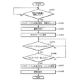
- FIG. 14 is a flowchart showing an example of a processing procedure of the security camera device according to the embodiment of the present invention.
- FIG. 1 shows a front view of the security camera device according to the embodiment of the present invention
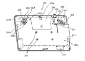
- FIG. 2 shows a rear view
- FIG. 3 shows a perspective view from the front side of the security camera device according to the embodiment of the present invention
- FIG. 4 shows a perspective view from the back side.
- the security camera device 100 has a flat plate shape.
- the security camera device 100 includes a housing 101 having a flat rectangular parallelepiped shape, and the housing 101 forms a flat plate shape.
- the security camera device 100 is installed with one surface (hereinafter referred to as “rear surface”) 101a of the flat plate-shaped housing 101 facing the inner wall surface side of the elevator cage (see FIG. 7 described later). In this way, the security camera device 100 can be retrofitted into the basket.
- a display screen (display) 102 is provided on the surface opposite to the back surface 101a (hereinafter referred to as "front surface 101b").
- the display screen 102 can be realized by, for example, a liquid crystal display (LCD: Liquid Crystal Display), an organic EL (Electro-Lumisensence) display, a 7-segment display, or the like.
- the front lens 103 (103a, 103b) is provided on the front 101b.
- the front lens 103a is provided so as to be located vertically below the display screen 102 in the housing 101 when it is installed in the basket.
- the front lens 103b is directed toward the display screen 102 on either the left or right side of the display screen 102 in the housing 101 (in FIGS. 1, 3, and 6). It may be provided so as to be located outside the end of the right).
- the front lens 103 may be provided with only one of 103a and 103b, or both 103a and 103b may be provided. Further, the number of front lenses 103 is not limited to one or two, and may be three or more.
- the front lens 103, together with the front image sensor, constitutes a front camera (see reference numeral 903 in FIG. 9), which is a photographing means according to the present invention.
- the front camera may include one or more lenses between the front lens 103 and the image sensor, a movable mechanism for moving at least one of the plurality of lenses along the optical axis direction, and the like. ..
- the front camera is realized by an AF unit that focuses by a passive method such as contrast AF (AutoFocus) or phase difference AF.
- the front lens 103b is configured to face downward by a predetermined angle with respect to the front plane.
- At least the front lens 103 is located vertically below the display screen 102 in the housing 101, or either the left or right end of the display screen 102 in the housing 101.
- the components other than the front lens 103 are not necessarily located below the display screen 102 in the vertical direction. You may.
- a speaker 104 and a status display LED (Light Emitting Diode) 105 are provided on the front 101b.
- the speaker 104 vibrates the diaphragm by an electric signal which is an audio signal to generate sound.
- the speakers 104 are provided on the left and right sides of the display screen 102 (left and right sides when installed in the basket).
- the speaker 104 may be an output terminal that outputs an audio signal, or an external speaker may be connected to the output terminal to generate sound.
- the number of external speakers to be connected may be one or two or more.
- the installation position of the speaker 104 is not limited to the left and right sides of the display screen.
- the status display LED 105 indicates the operating state of the security camera device 100. Specifically, the status display LED 105 indicates, for example, a power ON / OFF state, a link-up state, the presence / absence of data transmission / reception, the presence / absence of an error, a warning calling attention, and the like.
- the status display LED 105 is composed of a plurality of LED lamps 105a. Each of the plurality of LED lamps 105a may emit light in a different color, or each of the plurality of LED lamps 105a may appropriately switch a plurality of colors to emit light.
- the status display LED 105 indicates the operating state of the security camera device 100 depending on whether or not each LED lamp 105a is lit and the emission color.
- a power button 201 and an operation button 202 are provided on the back surface 101a. Each time the power button 201 is operated, the power of the security camera device 100 is switched ON / OFF.
- the operation button 202 is composed of a plurality of buttons 202a to 202f.
- buttons 202a and 202b accept, for example, an operation for adjusting the volume of the sound output from the speaker 104.
- the buttons 202c and 202d accept, for example, an operation of selecting a desired operation menu from a plurality of operation menus displayed on the setting screen displayed on the display screen 102 when the security camera device 100 is activated.
- Button 202e accepts the decision of the selected operation menu.
- the button 202e may be operated during the activation of the security camera device 100 to accept the operation of switching the display contents on the display screen 102. Specifically, by operating the button 202e while the security camera device 100 is activated, the display content such as an advertisement can be switched to the setting screen.
- the button 202f is operated while the security camera device 100 is activated to accept the start of shooting. Whether to shoot with the front camera or the rear camera can be selected by operating the buttons 202a to 202e.
- At least one of the power button 201 and the operation button 202 may be provided on the back surface 101a.
- the power button 201 may be provided on the back surface 101a
- the operation button 202 may be provided on the side surface (the surface other than the back surface 101a and the front surface 101b) or the front surface 101b of the housing 101.
- the operation button 202 may be realized by stacking a touch panel on the display screen 102 and using soft keys reproduced by software by the touch panel and the image displayed on the display screen 102.
- the back surface 101a is provided with a back cover 203, a back lens 204, a power switch 205 for a port, an external antenna mounting hole 206, a plurality of screw holes 207, an AC power connector 208, and an AC power cable fixing member 209. ing.
- the back cover 203 is detachably attached to the housing 101.
- the back cover 203 is fixed to the housing 101 using screws or the like.
- the screw for fixing the back cover 203 to the housing 101 it is preferable to use a special screw that cannot be operated with a general-purpose tool. Further, it is preferable that the back cover 203 is provided at a plurality of locations including at least two locations on both sides.
- the back cover 203 covers the ports and slots provided on the back 101a (both not shown) when attached to the housing 101.
- the port is responsible for inputting / outputting data to / from the outside of the security camera device 100, and can be specifically realized by, for example, a USB Type-A port.
- a plurality of ports may be provided.
- one is used as an interface with an external device such as a remote monitoring device for an elevator, and the other is a USB memory that records (records) the image in the basket taken by the security camera function. It can be used as an interface with the storage device of. As a result, it is possible to record (record) the image in the basket while operating in cooperation with the external device.
- the slot accepts the insertion of an expansion board, a memory card, or the like, and can be specifically realized by, for example, a SIM card slot or a MicroSD card slot.
- the back cover 203 is provided with a slit 203a.
- the cable (see reference numeral 502 in FIGS. 5 and 6) connecting the security camera device 100 and the external device via the port is externally connected from the slit 203a. Can be pulled out to. As a result, the degree of freedom of connection with the external device can be ensured.
- the rear lens 204 together with the rear image sensor, constitutes a rear camera (see reference numeral 904 in FIG. 9).
- the rear camera is used to read the property code (not shown) attached to the elevator to be installed when the security camera device 100 is installed.
- the property code can be realized by, for example, a two-dimensional code attached to the inner wall surface of the elevator car.
- the two-dimensional code may be read by the rear camera only when the security camera device 100 is installed, or may be read periodically after the installation or when predetermined conditions are met.
- the port power switch 205 switches the port power ON / OFF by being operated. As a result, power saving can be achieved by turning off the power when the port is not used.
- a port power switch 205 may be provided for each port. As a result, the power can be switched on / off for each port, and further power saving can be achieved.
- the external antenna mounting hole 206 is used for mounting an external antenna that is separate from the security camera device 100.
- the external antenna mounting hole 206 can be realized by, for example, an F-type connector.
- the F-type connector is connected to a receiving circuit (not shown) inside the housing 101.
- a screw for fixing the security camera device 100 to the inner wall surface of the basket is screwed into the screw hole 207.
- the security camera device 100 may be directly fixed to the inner wall surface of the basket by a screw, or may be fixed to the inner wall surface of the basket via a stay fixed to the inner wall surface of the basket. Good.
- the AC power connector 208 has a power supply plug (see reference numeral 501 in FIGS. 5 and 6) that can be inserted and removed, and receives power supply by inserting the power supply plug connected to the power supply.
- the AC power connector 208 accepts the insertion of a power supply plug included in a device called an AC (Alternating Current) adapter or the like, which is provided with a device that extracts a predetermined DC power from an alternating current input from an AC power supply (commercial power supply).
- the AC power connector 208 realizes the power connector according to the present invention.
- the power supply plug is connected to the AC power supply and is connected to the main body composed of a transformer circuit, a rectifying circuit, a regulated power supply circuit, etc. that extract a predetermined DC power from the AC power supply.
- the security camera device 100 By receiving power via the AC adapter, the security camera device 100 itself, which operates using a semiconductor element, can operate even if it is not equipped with a circuit that converts alternating current into direct current. As a result, the weight and cost of the security camera device 100 can be reduced.
- the security camera device 100 itself may include a circuit that converts alternating current into direct current.
- the AC adapter is not limited to the one that is normally connected to the AC power supply, and may include an outlet plug that receives power by being inserted into an outlet.
- the AC power cable fixing member 209 is used to fix the position of the cable continuous with the power supply plug inserted (connected) to the AC power connector 208.
- the AC power cable fixing member 209 has an arc shape in which both ends in the length direction are in contact with the back surface 101a, and a hole is formed by the arcuate inner peripheral surface and the back surface 101a.
- At least one end of the AC power cable fixing member 209 in the length direction is fixed to the back surface 101a.
- the other end of the AC power cable fixing member 209 in the length direction may not be fixed to the back surface 101a or may be separated from the back surface 101a. The method of fixing the cable using the AC power cable fixing member 209 will be described later (see FIGS. 5 and 6).
- Another port is provided at the lower part of the housing 101.
- Another port is responsible for inputting and outputting data to and from the outside of the security camera device 100, and specifically, for example, like the above port, it can be realized by a USB Type-A port.
- Another port is used, for example, when exporting the image data (recorded data of the security camera) taken by the security camera device 100 to the external device.
- the image data can be exported to the external device without removing the security camera device 100 from the inner wall surface of the basket or the back cover 203 from the housing 101. Can be done.
- the housing 101 may be provided with a cover 210 that covers another port.
- the cover 210 may be fixed to the housing 101 using screws or the like.
- As the screw for fixing the cover 210 it is preferable to use a special screw as well as the screw for fixing the back cover 203 described above. As a result, it is possible to prevent the image data from being illegally exported even when the port is provided in the lower part of the housing 101 in order to ensure good operability.
- FIGS. 5 and 6 are explanatory views showing a connection state between the AC power connector 208 and the power supply plug.
- the security camera device 100 can be powered and operated by inserting (connecting) a power supply plug 501 connected to the AC power supply into the AC power supply connector 208. ..
- the cable 502 connected to the power supply plug 501 for example, after inserting (connecting) the power supply plug 501 into the AC power connector 208, consideration is given to preventing disconnection of the cable 502 and preventing interference with surrounding members. Route it to any position. Then, after confirming that the routed cable 502 does not break and that the cable 502 does not interfere with surrounding members, the cable 502 is fixed to the AC power cable fixing member 209 using a binding band or the like. To do.
- the positional relationship between the AC power connector 208 and the power supply plug 501 is fixed to some extent, the free movement of the power supply plug 501 with respect to the AC power connector 208 is suppressed, and the elevator basket moves up and down. It is possible to prevent the power supply from being inadvertently stopped due to vibration or the like. Further, by fixing the position of the cable 502, it is possible to prevent mischief such as the cable 502 hanging down and spoiling the aesthetic appearance, or pulling the cable 502 to stop the power supply.
- FIG. 7 is an explanatory diagram showing an installation example of the security camera device 100 according to the embodiment of the present invention.
- FIG. 7 shows the inside of the elevator basket.
- the elevator car 701 is provided with a space for the occupant to ride inside, opens and closes the space and the outside, and is provided with a door 702 at the entrance / exit portion where the occupant enters and exits the basket 701.
- An operation panel 703 operated by an occupant on the basket 701 is provided on the inner wall surface of the basket 701.
- the operation panel 703 includes, for example, a group of operation buttons including a destination floor button, a door open / close button, an emergency button, and a display for displaying the floor on which the basket 701 is located.
- the operation panel 703 is an inner surface of the basket 701 and is provided on the same surface as the door 702.
- the security camera device 100 is the same wall surface as the wall surface on which the door 702 and the operation panel 703 are provided, and is installed near the ceiling above the operation panel 703. This assumes that the occupants in the basket 701 generally stand facing the wall surface on the door 702 side.
- the occupant in the basket 701 can display the display.
- the advertisement displayed on the screen 102 can be easily seen. As a result, a high advertising effect can be exhibited through the security camera device 100.
- the security camera device 100 captures the facial expressions of the occupants with, for example, a front camera. By installing the security camera device 100 near the ceiling, the facial expressions of the occupants can be easily photographed by the front camera. In addition, the front camera can capture the facial expressions of the occupants when getting out of the basket 701.
- the security camera device 100 by installing the security camera device 100 near the ceiling, the occupant cannot easily touch the security camera device 100 even if he / she reaches out in a normal state. Therefore, it is possible to prevent the occupant from inadvertently touching, illegally operating, or destroying the security camera device 100.
- the security camera device 100 may be provided on the wall surface (the wall surface on the back side of the basket 701) facing the wall surface on which the door 702 and the operation panel 703 are provided. By providing it on the wall surface on the back side of the basket 701, the occupant can see the security camera device 100 (display screen 102) when entering the basket 701.
- the security camera device 100 on the wall surface on which the door 702 and the operation panel 703 are provided and the wall surface facing the wall surface (the wall surface on the back side of the basket 701), the occupant can be inside the basket 701.
- the security camera device 100 (display screen 102) can be seen when entering and exiting the basket 701.
- the security camera device 100 may be provided on the side wall surface instead of the upper side of the same wall surface as the wall surface on which the door 702 and the operation panel 703 are provided. In this case, it is preferable that the security camera device 100 is provided at an upper position close to the ceiling on the side wall surface of the basket 701. Further, the security camera device 100 may be installed at a corner position in the corner of the basket 701. As described above, the security camera device 100 may be installed at any position above the upper end of the door 702 in the basket 701.
- the security camera device 100 can be retrofitted after the elevator is installed.
- the security camera device 100 includes the size of the basket 701 (capacity), the height of the ceiling of the basket 701, the shape of the basket 701 (the floor is square or rectangular, etc.), the type of elevator (see-through type, with or without a mirror on the wall surface). ), The type of outer door (with or without windows), etc. can be taken into consideration when installing in the optimum position. Further, the security camera device 100 may be capable of freely changing its installation position after the security camera device 100 is installed.
- the security camera device 100 can be installed, for example, by screwing it to the wall surface. By screwing the security camera device 100 to the wall surface, it is possible to reliably prevent the device from falling.
- the screwing may be applied not only to the wall surface but also to the ceiling of the basket 701 via a stay or the like.
- the security camera device 100 may be installed by a method other than screwing (for example, using a magnet or the like).
- the basket 701 is provided with a plug socket 704 that accepts the insertion of the outlet plug included in the AC adapter.
- the plug socket 704 constitutes a wiring plug connector together with the outlet plug by inserting the outlet plug provided in the AC adapter.
- an A type plug socket widely used in Japan can be used.
- the plug socket 704 is not limited to the A type. Specifically, for example, a B3 type or C type plug socket widely used in India or Indonesia may be used, or a BF type plug socket widely used in Hong Kong or the like may be used.
- an SE type plug socket widely used in South Korea or the like may be used, or an O type plug socket widely used in Taiwan or the like may be used.
- elevators are installed from various types such as A type, B type, C type, B3 type, BF type, SE type, and O type. It is preferable to use any type of plug socket according to the area where it is used.
- the plug socket 704 is electrically connected to the electric circuit of the board housed in the box on the basket. As a result, power can be supplied to the security camera device 100 via the plug socket 704 and the AC adapter.
- the plug socket 704 is not limited to the one directly connected to the terminal of the electric circuit of the board housed in the box on the basket, and may be connected to the power line connected to the terminal. When connecting the plug socket 704 to such a power line, a branching connector can be provided on the power line, and the plug socket 704 can be connected to the connector.
- the security camera device 100 does not have to make a separate hole for inserting the power supply cable 502 into the basket 701. Can be powered.
- the security camera device 100 can be easily and quickly installed without imposing a burden on the operator, and can be always operated without being stopped due to insufficient power. Further, even when an advertisement or the like is displayed on the display screen, it can be operated stably without being stopped due to insufficient power.
- the work time required for installing the security camera device 100 can be shortened, and the burden on elevator users and workers can be reduced.
- the basket 701 is provided with the plug socket 704, it is not necessary to backfill the through hole for inserting the power supply cable 502 into the basket 701, and the burden on the operator for the removal work is reduced. be able to. Further, it is possible to secure the aesthetic appearance in the basket 701 after the security camera device 100 is removed.
- the plug socket 704 When the plug socket 704 is exposed in the basket 701, it is preferable that the plug socket 704 is arranged at a high position in the basket 701 as shown in FIG. 7. Specifically, as shown in FIG. 7, the plug socket 704 is preferably provided on the side surface or the ceiling surface of the basket 701. By arranging the plug socket 704 exposed in the basket 701 at a high position in the basket 701 in this way, it is possible to prevent water droplets flying from the umbrella or clothes from adhering in rainy weather, and it is possible to prevent electric power theft or children. It can make mischief less likely.
- One plug socket 704 may be provided in one basket 701, or a plurality of plug sockets 704 may be provided in one basket 701.
- the plurality of plug sockets 704 may be arranged side by side or dispersed in a plurality of places.
- the plug socket 704 may be arranged, for example, so that the plug socket 704 is located on the same surface as the inner wall surface (ceiling surface) of the basket 701.
- the basket 701 may be provided with a plug seat, which is not shown, instead of the plug socket 704.
- the plug seat has a function of supplying power supplied from an electric circuit housed in a box on a basket (not shown) to the security camera device 100 connected to the plug seat.
- the resectorable may include wiring for signal transmission in addition to wiring for power supply.
- the resectorable that realizes the plug seat is preferably realized by a hot plug that can be inserted and removed during the operation of the security camera device 100 connected to the resectorable.
- the resectorable that realizes the plug seat may further supply power to the security camera device 100 via a control circuit (not shown).
- the plug seat may be realized by, for example, a USB connector.
- the USB connector as a resectorable that realizes the plug seat can be realized by resectorable of various known USB connectors such as a USB Type-A connector, a Micro USB connector, a Micro USB Type-B connector, and a USB Type-C connector. Can be done.
- the resectorable that realizes the plug seat is not limited to the USB interface connector (resectorable), for example, IEEE 1394 connector, PS / 2 connector, D-Sub connector, DIN connector, coaxial connector, and various other known connectors. It may be realized by the connector for communication of.
- One resectorable that realizes the plug seat may be provided in one basket 701, or a plurality of resectors may be provided in one basket 701.
- the number of types of communication I / F connectors may be one type or a plurality of types.
- the resectorable that realizes the plug seat can be arranged, for example, so that the end portion of the resectorable is located on the same surface as the inner wall surface of the basket 701. Further, the resectorable that realizes the plug seat may, for example, have the end portion of the resectorable protruding from the inner wall surface of the basket 701 to the inside of the basket 701, and is arranged at a position recessed from the inner wall surface of the basket 701. May be good.
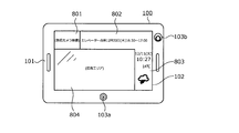
- FIG. 8 is an explanatory diagram showing an example of the appearance including the display contents of the security camera device according to the embodiment of the present invention.
- the display screen 102 of the security camera device 100 forms a long rectangle in the lateral direction and is surrounded by the housing 101.
- the display screen 102 can be displayed from a plurality of areas (four in this embodiment) such as a security camera image display area 801, a management information display area 802, various information display areas 803, and an advertisement display area (advertisement area) 804. It may be configured. In this way, by dividing the display into four areas and displaying the information, various information can be efficiently transmitted to the occupants.
- a security camera image display area 801, a management information display area 802, and various information display areas 803 are provided in an inverted "L" shape from the upper side to the right side so as to surround the rectangular advertisement display area 804 on the lower left side of the display screen 102.
- the security camera image display area 801 is provided on the left side, and subsequently, the management information display area 802 is provided horizontally. In the security camera image display area 801, the image taken by the front camera may be displayed in real time.
- this management information display area 802 if the message is long, the message is displayed so as to flow from the right side to the left side.
- the management information display area 802 is provided on the upper side of the display screen 102 so that the upper side of the display screen 102 is easily visible to the occupant, and therefore relatively important management information can be reliably transmitted to the occupant.
- various information display areas 803 are provided vertically on the right side surface to display various information to be notified to elevator occupants, such as weather forecasts, traffic information, and news as shown in FIG.
- various information display areas 803 when displaying a large amount of information, it may be displayed so as to flow from the lower side to the upper side.
- the information for the new region when displaying the weather forecast for each region, the information for the new region may be displayed sequentially from the bottom, and the information for the old region may be moved upward and then deleted. On the contrary, it may be displayed so as to flow from the upper side to the lower side. Further, it may be displayed so as to flow to either the left or right.
- the display form can be changed depending on the content of the information to be displayed.
- the management information display area 802 can be lengthened to the right side, and various information display areas 803 can be lengthened to the upper side according to the display situation. Further, depending on the information to be displayed, the management information display area 802 and various information display areas 803 can be used as a series.
- the display screen 102 By laying out the display screen 102 in this way, it is possible to display the advertisement information and at the same time convey other information to the occupants.
- the display screen 102 usually has a layout as shown in FIG. 8, but this layout may be changed depending on the situation. For example, in the event of an emergency such as an elevator failure, the advertising area may be erased to display the required information. Further, as an advertisement display effect, the entire surface of the display screen 102 may be used as an advertisement display.
- FIG. 9 is a block diagram showing an example of the hardware configuration of the security camera device 100 according to the embodiment of the present invention.
- the security camera device 100 includes a CPU (Central Processing Unit) 901, a memory 902, a front camera 903, a rear camera 904, a communication interface (I / F) 905, and a display screen (display). ) 102, a speaker 104, a microphone 906, a vibration sensor 907, an illuminance sensor 908, a contact sensor 909, a power control unit 910, a power button 201, and an operation button 202.
- Each component 102, 104, 201, 202, 901 to 910 is connected by a bus 900.
- the security camera device 100 includes tablet terminal devices (tablet terminals, tablet PCs), smartphones, notebook personal computers (mobile PCs), which include each component 102, 104, 201, 202, 901 to 910. It may be realized by using an information processing device such as a digital camera. In this way, an all-in-one, portable and portable information processing device that integrates multiple functions can be used as a security camera device. As a result, the security camera device 100 can be realized by a general-purpose device without separately developing and manufacturing a device dedicated to the elevator.
- the CPU 901 controls the entire device of the security camera device 100 by executing the program stored in the memory 902.
- the memory 902 can store various information including a program executed by the CPU 901. Further, the memory 902 may store advertisement information displayed on the display screen 102, image data captured by the front camera 903 and the rear camera 904, information regarding the date and time of capture, and the like.
- the memory 902 may be an internal memory built in the security camera device 100, for example, a hard disk memory, an IC memory, an SSD (Solid State Drive), or the like.
- the memory 902 may be a memory card that can be attached to and detached from the security camera device 100 via a card slot provided in the security camera device 100.
- the function of the memory card can be realized by, for example, an IC card such as an SD (Secure Digital) memory card.
- the memory card may realize its function by an external hard disk, a USB memory, an SSD, or the like.
- the front camera 903 includes a front image sensor, and acquires image information (photographed data) by converting the light received by the front image sensor through the front lens 103 into an electric signal.
- the front camera 903 may capture a still image or may capture a moving image.
- the moving image includes a continuous reproduction of still images taken at predetermined time intervals.
- the image information may be compressed by a standard of a predetermined video / audio data compression method (for example, MPEG (Moving Picture Experts Group) or the like).
- the rear camera 904 includes a rear image sensor, and acquires image information (photographed data) by converting the light received by the rear image sensor through the rear lens 204 into an electric signal.
- the rear camera 904 captures, for example, a still image.
- the image information may be compressed by a standard of a predetermined video / audio data compression method (for example, MPEG (Moving Picture Experts Group) or the like).
- the communication I / F905 is an interface for connecting the security camera device 100 and a network N such as the Internet through a communication line, controls the interface between the network N and the inside of the security camera device 100, and inputs data from an external device. And control the output of data to external devices.
- the CPU 901 may control the communication I / F 905 to acquire advertisement information from an advertisement distribution server or an advertiser's information terminal device (not shown) via the network N. Further, the CPU 901 may control the communication I / F905 to receive advertisement information from an information terminal device such as a smartphone carried by an elevator occupant.
- Communication I / F905 is, for example, a wireless interface using Wi-Fi (registered trademark). Further, the communication I / F905 may be a wireless communication interface such as a mobile phone line (for example, LTE (Long Term Evolution)) or PHS (Personal Handy-phone System), or may be a wired interface such as a modem or a LAN adapter. A communication interface can be adopted. Further, the elevator may be connected to a network provided for remote monitoring or the like, and information may be transmitted / received via the network. Further, the communication I / F905 may be realized by, for example, a USB interface.
- the display screen 102 is driven and controlled by the CPU 901 to display an advertisement or the like.
- the display screen 102 may display elevator management information such as a maintenance schedule.
- the management information is appropriately transmitted to the security camera device 100 by, for example, the administrator of the security camera device 100.
- the advertisement information and the management information may include information indicating a period (display start date and time, display end date and time, etc.) to be displayed on the display screen 102.
- the speaker 104 vibrates the diaphragm with an electric signal which is an audio signal to generate sound. Further, the speaker 104 may be an output terminal that outputs an audio signal, and an external speaker 104 may be connected to the output terminal to generate sound.
- the microphone 906 collects the sound in the basket 701.
- the vibration sensor 907 detects the vibration of the basket 701.
- the vibration sensor 907 can be realized by, for example, an acceleration sensor or the like.
- the illuminance sensor 908 detects the illuminance (brightness) in the basket 701.
- the illuminance sensor 908 can be realized by using, for example, a phototransistor or a photodiode.
- the contact sensor 909 detects, for example, that an object has come into contact with the surface of its own device (security camera device 100) including the display screen 102.
- the contact sensor 909 uses, for example, a resistance film method (a method of detecting by measuring a voltage change due to contact) and a capacitance method (a method of detecting a change in capacitance (charge), which is a weak current generated when contact is made).
- Sensor detection method ultrasonic method (method of detecting contact by attenuation of surface acoustic waves of ultrasonic waves), optical method (method of detecting contact by blocking infrared light using an infrared image sensor, etc.)
- Contact can be detected by a method such as).
- sensors such as an proximity sensor, a temperature sensor, and a humidity sensor may be provided.
- the power supply control unit 910 can be realized by, for example, a voltage adjusting unit (power supply IC or the like) that adjusts the voltage of the AC power supply supplied via the cable 502.
- the power control unit may be, for example, a transformer circuit, a rectifying circuit, or a stabilized power supply that extracts predetermined DC power from an outlet plug, a cable connected to the outlet plug, and an AC power supply supplied via the outlet plug. It may be configured by a circuit or the like.
- the security camera device 100 further includes a battery (storage battery) such as a lithium battery.
- the power supply control unit 910 may include a storage battery.
- the power control unit 910 may include a connection terminal for connecting a storage battery. As a result, the storage battery can be easily replaced.
- the power supply control unit 910 has the AC power supply connector 208, and supplies the power supplied to the AC power supply connector 208 to each component of the security camera device 100.
- the power button 201 or the operation button 202 Each time the power button 201 or the operation button 202 receives an operation, the power button 201 or the operation button 202 outputs a signal corresponding to the received button to the CPU 901.
- the CPU 901 drives and controls each unit based on the signals output from the power button 201 and the operation button 202 to switch the power ON / OFF, adjust the volume of the sound output from the speaker 104, and display the display screen.
- the display content in 102 is switched.
- the security camera device 100 may include a memory card I / F, an input / output device, a GNSS receiver, and the like.
- the memory card I / F is an interface connected to the security camera device 100 via the card slot.
- the memory card I / F controls the internal interface between the memory card and controls the input of data from the memory card and the output of data to the memory card.
- the input / output device can be realized by, for example, a key or a button for inputting characters, numbers, various instructions, and the like. Further, the input / output device may be realized by a microphone, a display (touch panel), a connection terminal to which another information processing device can be connected, or the like.
- GNSS Global Positioning Satellite System
- the GNSS receiver receives radio waves from three or five artificial satellites, receives radio waves from the artificial satellites, and outputs GNSS positioning data in order to obtain a geometric position with the artificial satellites.
- the current position of the security camera device 100 can be grasped by the GNSS receiver.
- the current position may be, for example, information about latitude and longitude. Further, the current position may be information about a base station performing wireless communication. When using the information about the base station as the current position, it is not necessary to use the GNSS receiver.
- FIG. 10 is a block diagram showing an example of the functional configuration of the security camera device according to the embodiment of the present invention.
- the security camera device 100 includes a control unit 1000, a photographing unit 1001, a photographing information storage unit 1002, a power supply unit 1003, a power storage unit 1004, a power supply monitoring unit 1005, and a power supply control unit 1006.
- arrows A to E indicate the flow of power supply.
- the control unit 1000 controls the entire security camera device 100. Specifically, the control unit 1000 can realize its function by, for example, the CPU 901 shown in FIG. 9 executing a program stored in the memory 902 or the like.
- the photographing unit 1001 photographs the inside of the basket 701.
- the photographing unit 1001 can realize its function by, for example, the front camera 903 shown in FIG. 9, that is, the front lenses 103 (103a, 103b) and the like.
- the shooting information storage unit 1002 stores image information and video information shot by the shooting unit 1001. Specifically, the shooting information storage unit 1002 can realize its function by, for example, the memory 902 shown in FIG. Further, the photographing information storage unit 1002 may realize its function by an external memory or the like (not shown). Further, the image information stored in the photographing information storage unit 1002 may be transmitted to an external device such as a management center via the network N by using the communication I / F905 shown in FIG.
- the power supply unit 1003 receives power (from the AC power connector 208) via the power supply plug 501 that supplies power to drive its own device (security camera device 100) including the photographing unit 1001 (arrow). A and arrow B), the received power is supplied to the own device (security camera device 100) (arrow C). Here, the arrow C is shown so as to supply power to the control unit 1000. This indicates that power is supplied to each component of the own device (security camera device 100) by supplying power to the control unit 1000 (the same applies to the arrow E described later). ..
- the power supply unit 1003 also supplies power to the power storage unit 1004 (arrow D).
- the power supply unit 1003 can realize its function by, for example, the power supply control unit 910 shown in FIG. Further, the power supply unit 1003 may realize the function by the CPU 901 executing the program stored in the memory 902 or the like.
- the power storage unit 1004 is provided in its own device (security camera device 100), and power is supplied by the power supply unit 1003 (arrow D) to store power. Specifically, the power storage unit 1004 can realize its function by, for example, the power supply control unit 910 shown in FIG.
- the power supply monitoring unit 1005 monitors the status of the power supply received by the power supply unit 1003.
- the power supply status is, for example, a situation in which the voltage of the power supply (arrow B) received by the power supply unit 1003 suddenly changes or the voltage becomes unstable.
- 1003 is in a situation where stable power cannot be supplied to each part of its own device (security camera device 100) including the photographing unit 1001. This corresponds to the case where the photographing by the photographing unit 1001 is hindered.
- the power supply monitoring unit 1005 detects that the supply (arrow A, arrow B) to the power supply unit 1003 via the power supply plug 501 has stopped.
- the power supply monitoring unit 1005 monitors the state of insertion / removal of the power supply plug 501 with respect to the AC power connector 208 into which the power supply plug 501 can be inserted / removed. In addition, the power supply monitoring unit 1005 monitors the state of the amount of electricity stored in the electricity storage unit 1004.
- the power supply monitoring unit 1005 can realize its function by, for example, the power supply control unit 910 shown in FIG. Further, the power supply monitoring unit 1005 may realize the function by the CPU 901 executing a program stored in the memory 902 or the like.
- the status of power supply monitoring by the power supply monitoring unit 1005, specifically, for example, the power supply unit 1003 supplies stable power to each part of its own device (security camera device 100) including the photographing unit 1001.
- the power supply (arrow C) from the power supply unit 1003 to the own device (security camera device 100) is switched to the supply (arrow E) from the power storage unit 1004.
- the power supply control unit 1006 detects that the power supply monitoring unit 1005 has stopped receiving the power supply unit 1003 (arrow B)
- the power supply control unit 1003 sends the power supply unit 1003 to its own device (security camera device 100).
- the power supply (arrow C) of the above may be switched to the supply (arrow E) from the power storage unit 1004.
- the suspension of receiving power to the power supply unit 1003 includes causes such as a power failure of the elevator, disconnection of the cable 502, and poor contact (cause that the supply of arrow A cannot be performed).
- the power supply control unit 1006 detects that the power supply plug 501 has been pulled out from the AC power connector 208 as a result of monitoring by the power supply monitoring unit 1005, the power supply control unit 1006 has its own device (security) from the power supply unit 1003.
- the supply of power to the camera device 100) (arrow C) may be switched to the supply from the power storage unit 1004 (arrow E).
- the power supply control unit 1006 detects that the power supply plug 501 has been inserted into the AC power connector 208 by the power supply monitoring unit 1005, the power supply control unit 1006 sends the power storage unit 1004 to its own device (security camera device 100).
- the power supply (arrow E) of the above may be switched to the supply (arrow C) from the power supply unit 1003.
- the supply of power (storage, arrow D) from the power supply unit 1003 to the power storage unit 1004 may be restarted.
- the power supply control unit 1006 may stop the supply of power to the display unit 1009 according to the state of the amount of electricity stored in the power storage unit 1004.
- the state of the amount of electricity stored in the electricity storage unit 1004 may be based on, for example, the monitoring result of the monitoring of the power supply monitoring unit 1005.
- the power supply control unit 1006 can realize its function by, for example, the CPU 901 shown in FIG. 9 executing a program stored in the memory 902 or the like. Further, the power supply control unit 1006 may realize the function by the CPU 901 executing the program stored in the memory 902 or the like.
- Advertisement information receiving unit 1007 receives advertisement information related to advertisements for elevator occupants. Specifically, the advertisement information receiving unit 1007 can realize its function by, for example, the communication I / F905 shown in FIG. The advertisement information receiving unit 1007 can receive advertisement information from an advertisement distribution server or an advertiser's information terminal device (not shown) via the network N. Further, the advertisement information receiving unit 1007 may receive the advertisement information from the information terminal device described later provided by the occupant of the elevator.
- the advertisement information storage unit 1008 stores the advertisement information received by the advertisement information reception unit 1007. Specifically, the advertisement information storage unit 1008 can realize its function by, for example, the memory 902 shown in FIG.
- the advertisement information storage unit 1008 may store the advertisement information received by the advertisement information receiving unit 1007 as it is, or the advertisement information once received by the advertisement information receiving unit 1007 may be displayed by the control unit 1000 for display. You may try to memorize the processed one.
- the display unit 1009 is composed of an advertisement information display control unit 1010 and a display screen 102.
- the display screen 102 is provided in front of the security camera device 100, and displays an advertisement in the basket 701 to the occupants of the basket 701.
- the advertisement information display control unit 1010 displays an advertisement on the display screen 102 based on the advertisement information received by the advertisement information receiving unit 1007 and stored in the advertisement information storage unit 1008. Further, the advertisement information display control unit 1010 may display information other than the advertisement on the display screen 102. Specifically, the advertisement information display control unit 1010 can realize its function by, for example, the CPU 901 shown in FIG. 9 executing a program stored in the memory 902 or the like.
- the advertisement information display control unit 1010 may display the advertisement information stored in the advertisement information storage unit 1008 on the display screen 102, and the control unit 1000 may display the advertisement information stored in the advertisement information storage unit 1008 on the display screen 102. After being processed by, it may be displayed on the display screen 102.
- the detection unit 1011 detects that an object has come into contact with its own device (security camera device 100) including the photographing unit 1001 and the display unit 1009. At that time, the detection unit 1011 determines the status of the functional failure of its own device (security camera device 100) (for example, power supply abnormality, display failure of the display screen 102, posture abnormality of its own device (security camera device 100), camera 903. , The failure of the captured image by the 904, the failure of the sound collection by the microphone 906, and the like, the failure caused by the contact of the object may be detected. Further, the degree of the failure may be detected. , Detected, or analyzed.
- the detection unit 1011 realizes its function by, for example, the contact sensor 909 or another sensor shown in FIG. 9, or by the CPU 901 executing a program stored in the memory 902 or the like. be able to. Further, the detection unit 1011 does not detect by one sensor (for example, contact sensor 909), but includes the contact sensor 909, or the object is based on the detection by a plurality of sensors excluding the contact sensor 900. It may be made to detect the contact with the security camera device 100).
- the detection unit 1011 realizes its function by, for example, the contact sensor 909 or another sensor shown in FIG. 9, or by the CPU 901 executing a program stored in the memory 902 or the like. be able to. Further, the detection unit 1011 does not detect by one sensor (for example, contact sensor 909), but includes the contact sensor 909, or the object is based on the detection by a plurality of sensors excluding the contact sensor 900. It may be made to detect the contact with the security camera device 100).
- the object that the detection unit 1011 detects contact with its own device may be an object, specifically, a baggage that is carried in or out of the basket.
- the own device security camera device 100
- the own device is attached at a position higher than the height of a person. Therefore, normally, when the occupant gets on and off, the human body does not come into contact with the own device (security camera device 100).
- the carrier may accidentally hit the load against its own device (security camera device 100) as shown in FIG. 11 to be described later.
- the object that the detection unit 1011 detects contact with the own device may be a human body, specifically, for example, a human hand or finger, or another part of the human body. ..
- a human hand or finger or another part of the human body. ..
- a tool held in the hand for example, a screwdriver. Therefore, if it can be detected that a human hand has touched or a tool has touched, it is easy that the security camera device 100 is about to be removed or that the security camera device 100 is about to be mischievous. Can be judged.
- the display unit 1009 (advertisement information display control unit 1010) that controls the display screen 102 and displays an advertisement to the occupant of the basket is, for example, own device (security camera) based on the detection result by the detection unit 1011.
- a password input screen (for example, the password input screen 1300 of FIG. 13 described later) is displayed on the display screen 102.
- the display unit 1009 controls the advertisement information display control unit 1010 to erase the contents displayed on the display screen 102 until then, and instead displays the password input screen. May be good.
- the password input screen may be displayed together with the contents displayed on the display screen 102 until then, or instead of a part of the contents displayed on the display screen 102 until then. The contents of the password input screen will be described in detail with reference to FIG. 13, which will be described later.
- the display unit 1009 may continue to display the password input screen displayed on the display screen 102 without erasing it, unless a valid password is input. Further, after the password input screen is once displayed, the display unit 1009 displays the password input screen without erasing it even if the power is turned off and reset, unless a valid password is input. You may keep doing it. In this way, it is possible to prevent a person who does not know the password from clearing the password input screen. If the password input screen is not erased, the display of the password input screen is obstructed, another display screen cannot be displayed on the display screen 102, and the function as a display device cannot be fully realized.
- the own device security camera device 100
- the function as the tablet terminal device cannot be fully exhibited unless the password input screen is erased, and it is difficult to reuse it. Therefore, even if it is stolen, its value as a target for resale is low.
- the alarm output unit 1012 outputs an alarm when the password input screen is displayed on the display screen 102 by the display unit 1009. Specifically, when the detection unit 1011 detects the contact of an object, it outputs an alarm. Specifically, the alarm output unit 1012 can realize its function by, for example, the CPU 901 shown in FIG. 9 executing a program stored in the memory 902 or the like. The alarm output unit 1012 outputs a warning sound or a predetermined sound from the voice output unit 1013.
- the audio output unit 1013 can realize its function by, for example, the speaker 104 shown in FIGS. 1, 3, 9, and the like.
- the warning sound may be an alarm, a siren, or the like.
- the predetermined voice may be, for example, characters on the password input screen displayed on the display screen 102, or another word (for example, "A contact has been detected. Please contact the management center immediately.” . ”) And so on.
- the alarm output unit 1012 outputs an alarm by turning on or blinking a light (lamp) provided in the security camera device 100 or separately attached, which is not shown. It may be.
- the carrier Since the alarm is output in this way, it can be expected that the thief will be surprised at this alarm and give up taking away his own device (security camera device 100).
- the package carrier since the package carrier may not be aware that the package has hit the own device (security camera device 100), the carrier can be made aware of it by outputting an alarm.
- the transmission unit 1013 transmits the shooting information to a predetermined server via the network.
- a given server includes, for example, a management center server.
- the identification information may be transmitted, for example, by uploading to a predetermined server via the network N.
- the transmission unit 1013 can realize its function by, for example, the communication I / F905 shown in FIG. Further, the transmission unit 1013 may realize the function by the CPU 901 executing a program stored in the memory 902 or the like.
- the reception unit 1011 accepts the password input.
- the password should only be known to workers who have the authority to unlock it (for example, elevator maintenance managers or building managers).
- the reception unit 1011 can realize its function by, for example, the power button 201, the operation button 202, the communication I / F905, and the like shown in FIG. Further, the reception unit 1011 may realize the function by the CPU 901 executing the program stored in the memory 902 or the like.
- the password can be entered by operating the operation button 202 of the own device (security camera device 100) or the touch panel provided on the display screen 102. At that time, for example, a soft keyboard or the like is displayed on the display screen 102. Further, the password may be input from an external device (not shown) by remote control using wireless communication.
- a two-dimensional code (for example, bar code, QR code (registered trademark)) containing information about the password displayed on the smartphone or tablet terminal of a worker who has the authority to unlock can be used as a front camera or a rear camera. You may enter the password by reading it into. Alternatively, a worker who has the authority to unlock the lock may be photographed, and the password may be input by various authentication processes such as biometric authentication of the worker's face and gesture authentication. In that case, specifically, the reception unit 1011 performs its function by, for example, the front camera 903 or the rear camera 904 and the CPU 901 shown in FIG. 9 executing a program stored in the memory 902 or the like. It can be realized.
- a two-dimensional code for example, bar code, QR code (registered trademark)
- QR code registered trademark
- a worker who has the authority to unlock the password may be made to utter a password, and the voice (content of words, voiceprint, etc.) may be recognized and processed to replace the password input.
- the reception unit 1011 can realize its function by, for example, the microphone 906 and the CPU 901 shown in FIG. 9 executing a program stored in the memory 902 or the like. ..
- the display unit 1009 displays the password displayed on the display screen 102.
- the input screen may be erased.
- the state before displaying the password input screen may be restored.
- the display of the advertisement on the display screen 102 may be restarted.
- the suspended advertisement may be resumed, or an advertisement different from the suspended advertisement may be displayed.
- the transmission unit 1015 provides notification information indicating that an object has come into contact with the own device (security camera device 100) and a password input screen is displayed on the display screen 102, for example, identification of the own device (security camera device 100).
- Information, information on the date and time of occurrence that is, the date and time when the password input screen 1300 is displayed), and the like are transmitted to a predetermined server via the network N shown in FIG.
- video information at a predetermined time before and after the occurrence date and time may also be transmitted. This makes it possible to analyze the cause of the contact.
- the transmission unit 1012 can realize its function by, for example, the communication I / F905 shown in FIG. Further, the transmission unit 1012 may realize the function by the CPU 901 executing a program stored in the memory 902 or the like.
- the identification information transmitted by the transmission unit 1015 may be an ID number unique to the security camera device 100 or the like, or may be an identification number of an elevator to which the security camera device 100 is attached.
- a given server includes, for example, a management center server.
- the identification information may be transmitted, for example, by uploading to a predetermined server via the network N.
- the transmission unit 1015 may create an e-mail containing the contents such as notification information, identification information, and information on the date and time of occurrence, and send the e-mail to a predetermined server. More specifically, for example, notification information, identification information, and information on the date and time of occurrence may be used as the body of the e-mail, and a file of notification information, identification information, and date and time of occurrence may be used as an attachment to create an e-mail. , May be sent. At that time, the body of the e-mail or the attached file may be encrypted. In this way, when creating and sending an e-mail, it is possible to simultaneously deliver it to a plurality of locations by designating a plurality of destinations. In addition, the destination can be easily changed by changing the e-mail address.
- the transmission unit 1015 may transmit notification information, identification information, information on the date and time of occurrence, and the like by communication using chat. Further, the transmission unit 1012 may use SNS (Social Networking Service) to transmit notification information, identification information, information on the date and time of occurrence, and the like.
- SNS Social Networking Service
- the transmission unit 1015 transmits the fact that the password input screen is displayed on the display screen 102 to the predetermined server via the network N, so that the management center or the like can grasp that fact more quickly and more reliably.
- the management center or the like can accurately grasp which security camera device 100 displayed the password input screen.
- the password input screen is displayed not only when an object such as luggage approaches, but also when a (malicious) passenger approaches or comes into contact with the security camera device 100 for the purpose of theft or mischief. Is also assumed. In that case, it is important for the management center to grasp the situation promptly and accurately.
- the control unit 1000 may restrict the input / output of data to the own device as an example of the lock process of the own device (security camera device 100). Good. Specifically, for example, the control unit 1000 may disable the process of receiving the advertisement information by the advertisement information receiving unit 1007. Therefore, the advertisement information receiving unit 1007 cannot receive the advertisement information. Further, the control unit 1000 may disable the process of storing the advertisement information and the process of extracting the stored data by the advertisement information storage unit 1008. Therefore, the advertisement information storage unit 1008 cannot store the advertisement information or extract the stored advertisement information.
- the control unit 1000 functions as a function of the photographing unit 1001 and a function of the photographing information storage unit 1002 as an example of the lock processing of the own device (security camera device 100). You may want to disable all or part of it. Therefore, the shooting information storage unit 1002 cannot store the shooting information or extract the stored shooting information. Further, the control unit 1000 may disable all or a part of the functions of the transmission unit 1012. As a result, it is possible to prevent the data stored in the own device (security camera device 100) from being taken out to the external device. Further, the control unit 1000 may not be able to use the USB connector when the password input screen is displayed. By doing so, for example, you can connect a PC to the USB connector, change the OS settings, extract installed software, edit, delete, install new software, execute software using debug mode, and analyze it. You can definitely prevent it from trying.
- the control unit 1000 continues the function of the photographing unit 1001 and continues shooting as an example of the lock processing of the own device (security camera device 100).
- the shooting information shot by the shooting unit 1001 may be continuously stored in the shooting information storage unit 1002. Therefore, the shooting process cannot be stopped during the lock. Then, the shooting information may be transmitted to a predetermined destination by wireless communication.
- the control unit 1000 uses a GNSS receiver or the like to determine information regarding the location of the own device (security camera device 100) by wireless communication. It may be sent to the destination of. These can facilitate the identification of thieves.
- the control unit 1000 has data stored in the own device (security camera device 100) as an example of the lock process of the own device (security camera device 100). You may want to erase all or part of. Specifically, the control unit 1000 erases all or part of the advertisement information stored in the advertisement information storage unit 1008, for example. As a result, the intellectual property rights of the advertiser, including the copyright of the advertising information, can be reliably protected. Further, the control unit 1000 erases all or a part of the shooting information stored in the shooting information storage unit 1002, for example. As a result, it is possible to reliably protect the portrait right and privacy of the person in the shooting information.
- FIG. 11 is an explanatory diagram showing an example of a contact situation of an object.
- a carrier 1100 such as a moving company or a courier company may use an elevator to carry the package 1101.
- the tip of the baggage 1101 or the like may come into contact with the security camera device 100.
- the security camera device 100 breaks down, is damaged, or has an accident.
- FIG. 12 is an explanatory diagram showing a state in which a power supply plug is inserted and removed from the AC power connector.
- FIG. 12 shows an example in which the AC power connector 208 is provided on the side surface of the housing 101, not on the back surface.
- an AC power connector is often provided on the side surface of the housing.
- FIG. 12A shows a state in which the power supply plug 501 is pulled out from the AC power connector 208. In this state, power is not supplied to the security camera device 100. Then, as shown by the arrow, the power supply plug 501 can be inserted into the AC power connector 208 by bringing the power supply plug 501 closer to the AC power connector 208.
- FIG. 12B shows a state in which the power supply plug 501 is inserted into the AC power connector 208.
- the security camera device 100 can receive power supply via the power supply plug 501.
- the power supply plug 501 can be inserted and removed from the AC power connector 208.
- the power supply monitoring unit 1005 monitors the state of insertion / removal of the power supply plug 501 for the AC power connector 208 shown in FIG.
- a sensor provided in the AC power connector 208 may be used to monitor the insertion / removal state of the power supply plug 501.
- FIG. 13 is an explanatory diagram showing an example of a password input screen.
- the display screen 102 of the security camera device 100 shown in FIG. 13 has a rectangular shape that is long in the horizontal direction, similar to the display screen 102 shown in FIG.
- On the display screen 102 as an example of the password input screen 1300, "Notice (Date and time of occurrence: 2019.12.10 21:48)", "The device will be locked because it was touched by the device", and "When locked, the data "Input / output will be restricted”, "The stored data will be deleted", "Please enter the password to unlock", etc. will be displayed, and the password entry field " ⁇ " will be displayed.
- ⁇ is displayed (Note that the number of digits (number of characters) and type of password can be set arbitrarily).
- “* If you do not enter the password correctly, it will not be reset even if the power is turned off” is displayed. Therefore, even if the power is turned off and restarted, the password input screen 1300 is displayed and the password input screen 1300 is not erased.
- the whole story of the crime is recorded by displaying "The security camera is operating normally" and displaying the image 1301 of the security camera device 100 on the display screen 102. Since we know in advance, we can infer that it will be more difficult to steal. Similarly, since it can be seen that the whole story of the crime is recorded, it can be expected that mischief (destruction, etc.) due to contact with the own device (security camera device 100) will be reduced. In addition, the recorded video data can be used as evidence for identifying the criminal (thief, mischievous person, etc.) together with the information on the date and time of occurrence.
- FIG. 14 is a flowchart showing an example of a processing procedure of the security camera device according to the embodiment of the present invention.
- This determination process is performed by, for example, the detection unit 1011 or the control unit 1000.
- step S1401: No waiting for the object to come into contact with the own device (step S1401: No)
- step S1401: Yes if the object touches (step S1401: Yes), the password input screen 1300 is displayed on the display screen 102, and the own device (security camera device). 100) is locked (step S1402).
- This display process is performed by, for example, the display unit 1009 (advertisement information display control unit 1010). Further, the lock process is performed by, for example, the control unit 1000, the shooting information storage unit 1002, the advertisement information storage unit 1008, the transmission unit 1012, and the like.
- step S1403 an alarm sound or voice is output from the speaker 104, or a blinking display of the display screen 102 is performed to output an alarm (step S1403).
- This output processing is performed by, for example, an alarm output unit 1012, a voice output unit, or the like.
- that fact, that is, the password input screen is displayed, and the predetermined destination (server) is notified that the own device (security camera device 100) is locked (step S1404).
- This transmission process is performed by, for example, the transmission unit 1015 or the like.
- step S1405 it is determined whether or not the password has been entered. This determination process is performed by, for example, the reception unit 1011 or the control unit 1000. Here, waiting for the password to be entered (step S1405: No), if the password is entered (step S1405: Yes), whether or not the passwords match, that is, the entered password is valid. It is determined whether or not it is a password (step S1406). This determination process is performed by, for example, the control unit 1000. Here, if the passwords do not match (step S1406: No), the process returns to step S1405, and the password is waited for input again.
- step S1406 if the passwords match (step S1406: Yes), the password input screen displayed on the display screen 102 is erased, and the lock of the own device (security camera device 100) is released (step S1407). At that time, the password input screen may be erased, and a predetermined destination may be notified that the lock of the own device (security camera device 100) has been released.
- This erasing process is performed, for example, by the display unit 1009 (advertisement information display control unit 1010). Further, the lock release process is performed by, for example, the control unit 1000. Further, this notification process is performed by the transmission unit 1012.
- step S1408 the alarm whose output is started in step S1403 is stopped.
- This stop processing is performed by, for example, an alarm output unit 1012, a voice output unit, or the like.
- a series of processes is completed. It should be noted that once the alarm is output, the output is continued until a valid password is input, but the configuration is not limited to this. If the alarm continues to be output, general occupants will be inconvenienced. Therefore, after a predetermined time has elapsed, the alarm output may be stopped even before a valid password is input. Further, the warning may be output at a relatively high volume immediately after the warning output is started, and may be switched to the warning at a relatively low volume after a predetermined time has elapsed. The volume and content of the warning output may be changed over time as appropriate.
- the security camera device 100 of the embodiment according to the present invention is a security camera device 100 which has a flat plate shape and is retrofitted with the back surface 101a facing the inner wall surface side of the elevator cage 701.
- the security camera device 100 of the embodiment according to the present invention when the security camera device 100 is installed in the basket 701, the security camera is provided by pulling out the power supply plug 501 from the AC power connector 208.
- the handleability of the device 100 is improved, and the security camera device 100 can be easily and quickly installed in the basket 701. As a result, it is possible to reduce the burden on the worker who installs the security camera device 100 and the work time required for the installation work, so that the burden on the worker can be reduced.
- the power supply plug 501 is inserted into the AC power connector 208 to stabilize the security camera device 100, which needs to be always activated. Can be powered. As a result, it is possible to eliminate a situation in which shooting is not possible due to insufficient power, to reliably shoot the inside of the basket 701, and to contribute to ensuring the safety of the occupants.
- the time when the elevator cannot be used for work can be shortened by shortening the work time.
- it is possible to prevent the convenience of the elevator user from being lowered and to ensure the convenience of the user.
- it can be easily and quickly installed in the basket 701 without deteriorating the convenience of the elevator user, and the safety of the occupant. It can contribute to securing.
- the security camera device 100 of the embodiment according to the present invention is characterized in that the AC power connector 208 is provided on the back surface 101a. According to the security camera device 100 of the embodiment according to the present invention, it is possible to make it difficult for the occupant to see the AC power connector 208 when the security camera is installed in the basket 701. As a result, it is possible to prevent the power supply from being stopped due to mischief of the occupant, reliably photograph the inside of the basket 701, and contribute to ensuring the safety of the occupant. Further, if the AC power connector 208 is provided on the side surface of the housing 101, there is a concern that the AC power connector 208 will be easily visible to the occupants and promote mischief. By making it difficult to see, it is possible to surely prevent the power supply from being stopped due to mischief of the occupant, and to secure the aesthetic appearance in the basket 701.
- the security camera device 100 of the embodiment according to the present invention is characterized in that at least one of the power button 201 and the operation button 202 is provided on the back surface 101a. According to the security camera device 100 of the embodiment according to the present invention, when the security camera is installed in the basket 701, it is difficult for the occupant to see the operation unit related to the operation of the security camera device 100 such as the power button 201 and the operation button 202. can do. As a result, it is possible to prevent the security camera device 100 from not operating normally due to mischief of the occupant, to reliably photograph the inside of the basket 701, and to contribute to ensuring the safety of the occupant.
- an operation unit related to the operation of the security camera device 100 such as a power button 201 or an operation button 202 is provided on the side surface of the housing 101, the operation unit is easily visible to the occupant, which facilitates mischief.
- the operation unit is easily visible to the occupant, which facilitates mischief.
- the security camera device 100 of the embodiment according to the present invention is characterized in that a display screen 102 for displaying an image or a moving image is provided on the front surface 101b.
- a display screen 102 for displaying an image or a moving image is provided on the front surface 101b.
- the security camera device 100 of the embodiment according to the present invention can be realized by a general-purpose tablet terminal device (tablet terminal, tablet PC, etc.) without separately developing and manufacturing a device dedicated to the elevator. it can.
- the tablet-type terminal device includes, for example, a CPU 901, a memory 902, cameras 903 and 904, a communication interface 905, a display screen (display) 102, and a power supply control unit 910.
- the security camera device 100 of the embodiment according to the present invention when the front camera 903 (at least the front lens 103 constituting the front camera 903) is installed in the basket 701, the security camera device 100 is vertically below the display screen 102.
- the feature is that it is provided so as to be located on the side.
- the front camera 903 since the front camera 903 (at least the front lens 103 constituting the front camera 903) is located below the display screen 102 in the vertical direction, the front camera The angle of view (shooting range) of the 903 can be easily adjusted. As a result, the inside of the basket 701 can be reliably photographed without being influenced by the shape and size of the basket 701, which can contribute to ensuring the safety of the occupants.
- the security camera device 100 of the embodiment according to the present invention is a security camera device that is retrofitted into the basket 701 of the elevator and photographs the inside of the basket 701, and includes a photographing unit 1001 that photographs the inside of the basket 701.
- Power is received via the power supply plug 501 that supplies power to drive the own device (security camera device 100) including the photographing unit 1001 (arrows A and B), and the received power is supplied to the own device (arrows A and B).
- the own device (security camera device 100) from the power supply unit 1003 according to the status of the power supply monitoring by the power supply monitoring unit 1004, the power supply monitoring unit 1005 that monitors the state of the power supply received by the power supply unit 1003, and the power supply monitoring unit 1005. ) Is provided with a power supply control unit 1006 that switches the power supply (arrow C) to the supply from the power storage unit 1004 (arrow E).
- a power supply control unit 1006 that switches the power supply (arrow C) to the supply from the power storage unit 1004 (arrow E).
- the power supply control unit 1006 detects that the power supply monitoring unit 1005 has stopped receiving power to the power supply unit 1003 (arrow B)
- the power supply is supplied. Since the power supply (arrow C) from the supply unit 1003 to the own device (security camera device 100) is switched to the supply from the power storage unit 1004 (arrow E), when a power failure or connection failure occurs. Even so, the power supply of the security camera device 100 can be reliably secured.
- the power supply monitoring unit 1005 monitors the insertion / removal state of the power supply plug 501 with respect to the AC power connector 208 into which the power supply plug 501 can be inserted / removed.
- the power supply control unit 1006 detects that the power supply plug 501 has been pulled out from the AC power connector 208 as a result of monitoring by the power supply monitoring unit 1005, the power supply control unit 1006 has its own device (security camera device) from the power supply unit 1003. Since the power supply to 100) is switched to the power supply from the power storage unit 1004, even if the power supply plug 501 is accidentally or artificially removed due to mischief, the security camera device 100 Power supply can be reliably secured.
- the power supply control unit 1006 detects that the power supply plug 501 has been inserted into the AC power connector 208 by the power supply monitoring unit 1005
- the power supply from the power storage unit 1004 to the own device (security camera device 100) is switched to the power supply from the power supply unit 1003
- the power storage unit (storage battery) 1004 can be prevented from being consumed, and the next power supply stop. Can be prepared for.
- the own device (security camera device 100) has a substantially flat plate shape, and one surface (“back surface”) of the flat plate is directed toward the inner wall surface side of the basket 701. Since it is installed and the photographing unit 1001 is provided on the surface opposite to the back surface (“front”), the security camera device 100 can be installed without protruding from the inner wall surface, and the space inside the basket 701 is effective. Can be used for.
- the security camera device 100 of the embodiment according to the present invention is provided on the front surface and includes a display unit 1009 having a display screen 102 for displaying an advertisement to the occupant of the basket 701 in the basket 701. It is possible to efficiently convey the content of the advertisement to the occupants.
- the security camera device 100 of the embodiment according to the present invention includes a detection unit 1011 for detecting that an object including a human body comes into contact with the own device including the photographing unit and the display unit, and the display unit 1009 (advertising information). Since the display control unit 1010) displays the password input screen 1300 on the display screen 102 based on the detection result by the detection unit 1011, it becomes easy to know that the object has touched the own device (security camera device 100). .. In addition, it is possible to notify that the password must be entered for recovery. As a result, even if the thief removes his / her own device (security camera device 100) and takes it out, he / she can be informed that the own device cannot be reused without knowing the password. As described above, since the device can be easily retrofitted and removed, the possibility of the device being stolen or mischievous can be reduced, and a stable shooting operation can be ensured. As a result, it is possible to contribute to ensuring the safety of the occupants.
- the display unit 1009 (advertisement information display control) Since unit 1010) erases the password input screen 1300 displayed on the display screen 102 and resumes the display of the advertisement, the recovery process can be easily performed by an operation by an operator who knows the password. Also, if you do not know the password, you cannot perform the recovery process.
- the transmission unit 1012 transmits that the password input screen 1300 is displayed to a predetermined server via the network, so that a password input operation is required. It is possible to inform the concerned parties of such things more quickly. In addition, it is possible to accurately grasp which security camera device 100 is in contact with. Therefore, a quick response for recovery is possible, and a more stable shooting operation can be ensured. As a result, it is possible to contribute to ensuring the safety of the occupants.
- the security camera device control program of the embodiment according to the present invention is retrofitted into the basket of the elevator, and displays an advertisement to the photographing unit 1001 for photographing the inside of the basket and the occupants of the basket in the basket.
- the security camera device control program of the embodiment according to the present invention limits the input / output of data to the own device (security camera device 100) when the password input screen 1300 is displayed on the display screen 102. Even if the own device (security camera device 100) is stolen, it is possible to prevent the own device (security camera device 100) from being misused.
- the security camera device control program has all or one of the data stored in the own device (security camera device 100) when the password input screen 1300 is displayed on the display screen 102. Since the part is erased, it prevents the recorded data from being misused, and ensures that the intellectual property rights such as the copyright of the advertiser and the portrait rights of the occupants related to the data are unfairly infringed. Can be blocked.
- the security camera device according to the present invention is useful for a security camera device that photographs the inside of a basket for the purpose of crime prevention, and in particular, a security camera device that can ensure stable operation of a security camera function. Are suitable.
Landscapes
- Engineering & Computer Science (AREA)
- Civil Engineering (AREA)
- Mechanical Engineering (AREA)
- Structural Engineering (AREA)
- Indicating And Signalling Devices For Elevators (AREA)
- Cage And Drive Apparatuses For Elevators (AREA)
- Alarm Systems (AREA)
Abstract
エレベーターのカゴ内に後付けされ、当該カゴ内を撮影する防犯カメラ装置(100)が、当該装置に物体が接触したことを検知した場合に、パスワード入力画面(1300)を表示画面(102)に表示し、また、防犯カメラ装置(100)をロックし、データの入出力を制限し、データを消去し、当該装置を盗み出しても再利用できないようにする。これにより、防犯カメラ装置(100)の盗難事件の発生、および、防犯カメラ装置(100)に対する荷物などのいわゆる当て逃げを抑制する。また、仮に、防犯カメラ装置(100)を持ち去られても、防犯カメラ装置(100)内のデータの悪用を防止し、広告データにかかる広告主の著作権などの知的財産権や撮影データにかかる乗員の肖像権などのプライバシーを保護する。
Description
この発明は、エレベーターのカゴ内を撮影する防犯カメラ装置および防犯カメラ装置制御プログラムに関する。
エレベーターのカゴ内における防犯を目的として、カゴ内を撮影する防犯カメラ装置を設置したエレベーターが数多く存在する。
関連する技術として、具体的には、従来、たとえば、エレベーターのカゴ内に設置されたコンピュータ(情報処理装置)に、エレベーターの乗員に対して画像を表示する第1の処理と、第1の処理によって表示される画像を見ている乗員を撮影する第2の処理と、第2の処理によって撮影された情報を記憶する第3の処理と、を実行させることにより、エレベーターの乗員に対して情報を提供するとともに、エレベーター内で発生するおそれがある犯罪行為などを抑止し、エレベーター内の防犯に寄与するようにした防犯支援プログラムに関する技術があった。また、画像を表示する表示画面と、表示画面と同一面に、カゴ内を撮影する撮像部とを有する情報処理装置と、情報処理装置を支持する支持部材と、を備え、エレベーターのカゴの内壁面に設置され、エレベーターの乗員に対して画像を表示する表示装置に関する技術があった(たとえば、下記特許文献1、2を参照。)。
しかしながら、防犯カメラ装置は、新規に設置されるエレベーターに備え付けられていることが多く、設置時に防犯カメラ装置を備えているエレベーターは、一般的に、高価なエレベーターに限定される傾向にある。設置時において防犯カメラ装置を備えていないエレベーターに防犯カメラ装置を後付けするためには、大掛かりな工事が必要になり、工事のためにエレベーターを利用できない期間が長くなり、エレベーターの利用者の利便性が低下してしまうという問題がある。
一方で、費用の面から防犯カメラ装置の設置を先送りすることは、乗員の安全確保が不十分であり好ましくなく、また、エレベーターのカゴ内での犯罪やトラブルが発生しても特定や検証することができず、防犯面において問題がある。
また、特許文献1、2の発明にかかる表示装置は、情報処理装置が、カゴ内を撮影する撮像部を有し、その撮像部によって防犯カメラとしても機能を備えている旨を開示しているが、当該情報処理装置では、当該撮像部へ供給される電源を管理することはできない。一般的に、災害の発生時や犯罪の発生時など、(自然発生的に、または、人為的に)通常供給される電源が停止される状況あるいは電源が不安定になる状況が生じる可能性があり、その状況にこそ、防犯カメラによるカゴ内の撮影映像を記録したり、管理センターなどの外部へ出力したりすることが有用になる。
このように、防犯カメラにおいて電源を確保し撮影し続けることが重要な課題である。また、通常供給される電源が停止され、非常用の電源に切り替わった場合には、一刻も早く復旧させることが重要である。特許文献1の発明にかかる表示装置は、そのことについては何ら解決されていない。そもそも、特許文献1の発明にかかる表示装置を構成する情報処理装置がどのように電源を確保するかについて不明で、後付けの装置であるゆえに、十分に防犯カメラ付き表示装置としての機能を有してはおらず、当該装置では、エレベーター内における情報表示および防犯を果たすことができないという問題点がある。
また、エレベーターのカゴ内に後付けの防犯カメラ装置は、取り外しが容易なゆえに、盗難にあったり、悪戯されたりする可能性が高い。一旦、盗まれたり、破壊されたりすると、復旧させるまでの間、防犯カメラが作動しないため、防犯の抑止力が低下する。また、防犯カメラ装置を広告表示装置としても使用する場合には、復旧するまでの間、広告が表示できないので、広告提供者(広告主)の広告活動にも支障を来すことになるという問題点がある。
この発明は、上述した従来技術による問題点を解消するため、後付けで取り外しが容易なゆえに、壊されたり、盗難にあったり、悪戯されたりする可能性が高い装置の当該可能性を低減させ、安定した撮影動作を確保することができる。それにより、乗員の安全確保に寄与することができる防犯カメラ装置および防犯カメラ装置制御プログラムを提供することを目的とする。
上述した課題を解決し、目的を達成するため、この発明にかかる防犯カメラ装置は、エレベーターのカゴ内に後付けされ、当該カゴ内を撮影する防犯カメラ装置であって、前記カゴ内を撮影する撮影部と、前記カゴ内で当該カゴの乗員に対して広告を表示する表示画面を有する表示部と、前記撮影部および前記表示部を含む自装置に物体が接触したことを検知する検知部と、を備え、前記表示部が、前記検知部による検知結果に基づいて、パスワード入力画面を前記表示画面に表示することを特徴とする。
また、この発明にかかる防犯カメラ装置は、上記の発明において、前記物体が、人体を含むことを特徴とする。
また、この発明にかかる防犯カメラ装置は、上記の発明において、前記表示部によって前記パスワード入力画面が前記表示画面に表示された場合に、警報を出力する警報出力部を備えたことを特徴とする。
また、この発明にかかる防犯カメラ装置は、上記の発明において、パスワードの入力を受け付ける受付部を備え、前記受付部によって受け付けられたパスワードがあらかじめ登録されているパスワードと一致した場合に、前記表示部が、前記表示画面に表示した前記パスワード入力画面を消去し、前記広告の表示を再開することを特徴とする。
また、この発明にかかる防犯カメラ装置は、上記の発明において、前記パスワード入力画面が表示されたことを、ネットワークを介して所定のサーバへ送信する送信部を備えたことを特徴とする。
また、この発明にかかる防犯カメラ装置は、上記の発明において、前記自装置が、略平板形状をなし、平板の一面(以下「背面」という)を前記カゴの内壁面側に向けて設置され、前記表示画面が、前記背面とは反対の面(以下「正面」という)に設けられ、前記撮影部が、前記正面であって、前記表示画面の周辺に設けられることを特徴とする。
また、この発明にかかる防犯カメラ装置は、上記の発明において、前記自装置が、CPU(Central Processing Unit)と、メモリと、カメラと、通信インタフェースと、ディスプレイと、電源制御ユニットと、を備えたタブレット型端末装置によって構成されることを特徴とする。
また、この発明にかかる防犯カメラ装置制御プログラムは、エレベーターのカゴ内に後付けされ、当該カゴ内を撮影する撮影部と、当該カゴ内で当該カゴの乗員に対して広告を表示する表示画面と、を備える防犯カメラ装置に、前記自装置に物体が接触したことを検知し、検知結果に基づいて、パスワード入力画面を前記表示画面に表示する、処理を実行させることを特徴とする。
また、この発明にかかる防犯カメラ装置制御プログラムは、上記の発明において、前記パスワード入力画面が前記表示画面に表示された場合に、前記自装置に対するデータの入出力を制限することを特徴とする。
また、この発明にかかる防犯カメラ装置制御プログラムは、上記の発明において、前記パスワード入力画面が前記表示画面に表示された場合に、前記自装置に記憶されているデータの全部または一部を消去することを特徴とする。
また、この発明にかかる防犯カメラ装置は、上記の発明において、前記電源監視部が、前記電源供給用プラグを挿抜可能な電源コネクタに対する当該電源供給用プラグの挿抜の状態を監視し、前記電源供給制御部が、前記電源監視部による監視の結果、前記電源コネクタから前記電源供給用プラグが抜出されたことを検出した場合に、前記電源供給部からの前記自装置への電源の供給を、前記蓄電部からの供給へと、切り替えることを特徴とする。
この発明にかかる防犯カメラ装置によれば、また、後付けで取り外しが容易なゆえに、壊されたり、盗難にあったり、悪戯されたりする可能性が高い装置の当該可能性を低減させ、安定した撮影動作を確保することができる。それにより、乗員の安全確保に寄与することができるという効果を奏する。
以下に添付図面を参照して、この発明にかかる防犯カメラ装置および防犯カメラ装置制御ブログラムの好適な実施の形態を詳細に説明する。
(防犯カメラ装置の外観構成)
まず、この発明にかかる実施の形態の防犯カメラ装置の外観構成について説明する。図1~図4は、この発明にかかる実施の形態の防犯カメラ装置の外観構成を示す説明図である。図1においてはこの発明にかかる実施の形態の防犯カメラ装置の正面図を示し、図2においては背面図を示している。図3においてはこの発明にかかる実施の形態の防犯カメラ装置の正面側からの斜視図を示し、図4においては背面側からの斜視図を示している。
まず、この発明にかかる実施の形態の防犯カメラ装置の外観構成について説明する。図1~図4は、この発明にかかる実施の形態の防犯カメラ装置の外観構成を示す説明図である。図1においてはこの発明にかかる実施の形態の防犯カメラ装置の正面図を示し、図2においては背面図を示している。図3においてはこの発明にかかる実施の形態の防犯カメラ装置の正面側からの斜視図を示し、図4においては背面側からの斜視図を示している。
図1~図4に示すように、この発明にかかる実施の形態の防犯カメラ装置100は、平板形状をなす。具体的に、防犯カメラ装置100は、扁平な長方体形状をなす筐体101を備えており、当該筐体101によって平板形状をなす。防犯カメラ装置100は、平板形状をなす筐体101の一面(以下「背面」という)101aを、エレベーターのカゴの内壁面側に向けた状態で設置される(後述する図7を参照)。このようにして、防犯カメラ装置100は、カゴ内に後付けすることができる。
防犯カメラ装置100の筐体101において、背面101aとは反対の面(以下「正面101b」という)には、表示画面(ディスプレイ)102が設けられている。表示画面102は、具体的には、たとえば、液晶表示器(LCD:Liquid Crystal Display)、有機EL(Electro-Luminescence)ディスプレイ、7セグメントディスプレイなどによって実現することができる。
また、正面101bには、正面レンズ103(103a、103b)が設けられている。正面レンズ103aは、カゴ内に設置された状態において、筐体101における、表示画面102より鉛直方向下側に位置するように設けられている。また、正面レンズ103bは、図1、図3、図6に示すように、筐体101における、表示画面102の左右のいずれか(図1、図3、図6では、表示画面102に向かって右)の端部の外側に位置するように設けられるようにしてもよい。正面レンズ103は、103a、103bのどちらか1つだけ設けられていてもよく、また、103a、103bの両方が設けられていてもよい。また、正面レンズ103の数は、1つまたは2つに限らず、3つ以上であってもよい。正面レンズ103は、正面用撮像素子とともに、この発明にかかる撮影手段である正面カメラ(図9における符号903を参照)を構成する。
正面カメラは、正面レンズ103と撮像素子との間に1または複数のレンズや、当該複数のレンズのうちの少なくとも1つのレンズを光軸方向に沿って移動させる可動機構などを備えていてもよい。正面カメラは、具体的には、たとえば、コントラストAF(AutoFocus)や位相差AFなどのパッシブ方式により焦点を合わせるAFユニットによって実現される。
また、正面レンズ103bは、正面の平面に対して所定の角度だけ下側を向くように構成されている。これにより、平板形状の筐体101を壁面に取り付けて、表示画面102が、壁面と平行になった場合であっても、カゴ内の下側の領域を確実に撮影することができる。
なお、正面カメラの構成部品のうち、少なくとも正面レンズ103が、筐体101における、表示画面102より鉛直方向下側に位置、または、筐体101における、表示画面102の左右のいずれかの端部の外側に位置していればよく、筐体101の形状や筐体101内の部品の配置によっては、正面レンズ103以外の構成部品は、必ずしも表示画面102より鉛直方向下側に位置していなくてもよい。
また、正面101bには、スピーカー104やステータス表示LED(Light Emitting Diode)105が設けられている。スピーカー104は、音声信号である電気信号によって振動板を振動させて音を発生させる。スピーカー104は、表示画面102の左右(カゴ内に設置された状態における左右)にそれぞれ設けられている。スピーカー104は、音声信号を出力する出力端子であってもよく、当該出力端子に外部スピーカーを接続して、音を発生させるようにしてもよい。接続する外部スピーカーは、1台であってもよく、2台以上であってもよい。スピーカー104の設置位置も、表示画面の左右には限定されない。
ステータス表示LED105は、防犯カメラ装置100の動作状態を示す。具体的に、ステータス表示LED105は、たとえば、電源のON/OFF状態、リンクアップ状態、データ送受信の有無、エラー発生の有無、注意を促す警告などを示す。ステータス表示LED105は、複数のLEDランプ105aによって構成されている。複数のLEDランプ105aは、それぞれが異なる色で発光するものであってもよく、それぞれが複数色を適宜切り替えて発光するものであってもよい。ステータス表示LED105は、各LEDランプ105aの点灯の有無や発光色によって防犯カメラ装置100の動作状態を示す。
背面101aには、電源ボタン201および操作ボタン202が設けられている。電源ボタン201は、操作されるごとに、防犯カメラ装置100の電源のON/OFFを切り替える。操作ボタン202は、複数のボタン202a~202fによって構成されている。
具体的に、ボタン202a、202bは、たとえば、スピーカー104から出力される音声の音量の調整操作を受け付ける。ボタン202c、202dは、たとえば、防犯カメラ装置100の起動時に表示画面102に表示される設定画面に表示される複数の操作メニューの中から所望の操作メニューを選択する操作を受け付ける。ボタン202eは、選択された操作メニューの決定を受け付ける。
ボタン202eは、防犯カメラ装置100の起動中に操作されることにより、表示画面102における表示内容の切り替え操作を受け付けてもよい。具体的には、防犯カメラ装置100の起動中におけるボタン202eの操作により、たとえば、広告などの表示内容を設定画面に切り替えることができる。
ボタン202fは、防犯カメラ装置100の起動中に操作されることにより、撮影開始を受け付ける。正面カメラおよび背面カメラのいずれの撮影をおこなうかは、ボタン202a~202eの操作によって選択することができる。
電源ボタン201および操作ボタン202は、少なくとも一方が背面101aに設けられていればよい。具体的には、たとえば、電源ボタン201を背面101aに設け、操作ボタン202を筐体101の側面(背面101aおよび正面101b以外の面)や正面101bに設けてもよい。また、表示画面102にタッチパネルを積層し、当該タッチパネルと表示画面102に表示する画像とによってソフトウェア的に再現されるソフトキーによって操作ボタン202を実現してもよい。
また、背面101aには、背面蓋203、背面レンズ204、ポート用電源スイッチ205、外部アンテナ取付穴206、複数のビス穴207、AC電源コネクタ208、および、AC電源ケーブル固定用部材209が設けられている。背面蓋203は、筐体101に対して取り外し可能に取り付けられている。背面蓋203は、ネジなどを用いて筐体101に固定されている。
背面蓋203を筐体101に固定するネジは、汎用的な工具では操作することができない特殊ネジを用いることが好ましい。また、背面蓋203は、少なくとも両脇の2ヵ所を含む複数箇所に設けることが好ましい。背面蓋203は、筐体101に取り付けられた状態において、背面101aに設けられたポートやスロット(いずれも図示を省略)を覆う。
ポートは、防犯カメラ装置100の外部とのデータの入出力を担い、具体的には、たとえば、USB Type-Aポートによって実現することができる。ポートは、複数設けられていてもよい。ポートを複数設ける場合、たとえば、1つをエレベーターの遠隔監視装置などの外部装置とのインタフェースとして用い、別の1つを防犯カメラ機能により撮影したカゴ内の画像を記録(録画)するUSBメモリなどの記憶装置とのインタフェースとして用いることができる。これにより、外部装置と連携して動作しつつ、カゴ内の画像を記録(録画)することができる。スロットは、拡張ボードやメモリカードなどの挿入を受け付け、具体的には、たとえば、SIMカードスロットやMicroSDカードスロットによって実現することができる。
背面蓋203には、スリット203aが設けられている。これにより、ポートおよびポートと端子との接続を保護しつつ、ポートを介して防犯カメラ装置100と外部装置などとを接続するケーブル(図5および図6における符号502を参照)をスリット203aから外部に引き出すことができる。そして、これにより、外部機器との接続の自由度を確保することができる。
背面レンズ204は、背面用撮像素子とともに、背面カメラ(図9における符号904を参照)を構成する。背面カメラは、防犯カメラ装置100の設置に際して、設置対象となるエレベーターに貼り付けてある物件コード(図示を省略する)の読み込みに用いる。物件コードは、たとえば、エレベーターのカゴの内壁面に貼り付けられた二次元コードによって実現することができる。背面カメラによる二次元コードの読み込みは、防犯カメラ装置100の設置時のみおこなってもよく、設置後も定期的あるいは所定の条件が整った場合におこなってもよい。
防犯カメラ装置100の設置後に定期的あるいは所定の条件が整った場合に、背面カメラによる二次元コードの読み込みをおこなうことにより、防犯カメラ装置100が正規の位置に取り付けられていることを確認することができ、防犯カメラ装置100の不正な持ち出しを抑制することができる。
ポート用電源スイッチ205は、操作されることにより、ポートの電源のON/OFFを切り替える。これにより、ポートを使わない場合は電源をOFFすることによって、省電力化を図ることができる。防犯カメラ装置100が複数のポートを備える場合、ポートごとにポート用電源スイッチ205を設けてもよい。これにより、ポートごとに電源のON/OFFを切り替えることができ、一層の省電力化を図ることができる。
外部アンテナ取付穴206は、防犯カメラ装置100とは別体の外部アンテナの取り付けに用いる。具体的に、外部アンテナ取付穴206は、たとえば、F型コネクタによって実現することができる。F型コネクタは、筐体101の内部において、図示を省略する受信回路に接続されている。
ビス穴207には、防犯カメラ装置100をカゴの内壁面に固定するためのビスが螺合される。防犯カメラ装置100は、ビスによって、カゴの内壁面に直接固定されるものであってもよく、カゴの内壁面に固定されるステーを介してカゴの内壁面に固定されるものであってもよい。
AC電源コネクタ208は、電源供給用プラグ(図5および図6における符号501を参照)を挿抜可能であって、電源に接続された電源供給用プラグが挿入されることによって電力の供給を受け付ける。AC電源コネクタ208は、たとえば、AC(Alternating Current)アダプターなどと称される、AC電源(商用電源)より入力される交流から所定の直流電力を取り出す機器が備える電源供給用プラグの挿入を受け付ける。AC電源コネクタ208は、この発明にかかる電源コネクタを実現する。
ACアダプターにおいて、電源供給用プラグは、AC電源に接続され、AC電源の交流から所定の直流電力を取り出す変圧回路、整流回路、安定化電源回路などによって構成される本体部に接続される。ACアダプターを介して給電を受けることにより、半導体素子を利用して動作する防犯カメラ装置100自体が、交流を直流に変換する回路を搭載していなくても動作することができる。これにより、防犯カメラ装置100の軽量化、低コスト化を図ることができる。なお、防犯カメラ装置100自体が、交流を直流に変換する回路を備えていてもよい。ACアダプターは、AC電源に常態的に接続されているものに限らず、コンセントに挿入されることによって給電を受けるコンセントプラグを備えていてもよい。
AC電源ケーブル固定用部材209は、AC電源コネクタ208に挿入(接続)された電源供給用プラグに連続するケーブルの位置の固定に用いる。具体的に、AC電源ケーブル固定用部材209は、長さ方向における両端が背面101aに接して設けられた円弧形状をなし、円弧形状の内周面と背面101aとによって孔を形成する。
AC電源ケーブル固定用部材209は、少なくとも長さ方向における一端が背面101aに固定されている。AC電源ケーブル固定用部材209の長さ方向における他端は、背面101aに固定されていなくてもよく、背面101aから離間していてもよい。AC電源ケーブル固定用部材209を利用したケーブルの固定方法については、後述する(図5および図6を参照)。
さらに、防犯カメラ装置100がカゴ内に設置された状態における、筐体101の下部には、図示を省略する別のポートが設けられている。別のポートは、防犯カメラ装置100の外部とのデータの入出力を担い、具体的には、たとえば、上記のポートと同様に、USB Type-Aポートによって実現することができる。別のポートは、たとえば、防犯カメラ装置100が撮影した画像データ(防犯カメラ録画データ)を外部装置にエクスポートする際に使用する。別のポートを筐体101の下部に設けることにより、防犯カメラ装置100をカゴの内壁面から取り外したり、背面蓋203を筐体101から取り外したりすることなく、画像データを外部装置にエクスポートすることができる。
筐体101には、別のポートを覆うカバー210が設けられていてもよい。このカバー210は、ネジなどを用いて筐体101に固定されていてもよい。カバー210を固定するネジも、上述した背面蓋203を固定するネジと同様に、特殊ネジを用いることが好ましい。これにより、良好な操作性を確保するために、筐体101の下部にポートを設ける場合にも、画像データが不正にエクスポートされることを防止できる。
(AC電源コネクタ208と電源供給用プラグとの接続状態)
つぎに、AC電源コネクタ208と電源供給用プラグとの接続状態について説明する。図5および図6は、AC電源コネクタ208と電源供給用プラグとの接続状態を示す説明図である。防犯カメラ装置100は、図5および図6に示すように、AC電源コネクタ208に、AC電源に接続された電源供給用プラグ501が挿入(接続)されることによって給電され、動作することができる。
つぎに、AC電源コネクタ208と電源供給用プラグとの接続状態について説明する。図5および図6は、AC電源コネクタ208と電源供給用プラグとの接続状態を示す説明図である。防犯カメラ装置100は、図5および図6に示すように、AC電源コネクタ208に、AC電源に接続された電源供給用プラグ501が挿入(接続)されることによって給電され、動作することができる。
電源供給用プラグ501に接続されたケーブル502は、たとえば、電源供給用プラグ501をAC電源コネクタ208に挿入(接続)した後、ケーブル502の断線防止や周囲の部材との干渉防止などを考慮した任意の位置に引き回す。そして、引き回したケーブル502が断線しないことや、当該ケーブル502が周囲の部材に干渉しないことなどを確認してから、当該ケーブル502を、結束バンドなどを用いてAC電源ケーブル固定用部材209に固定する。
これにより、AC電源コネクタ208と電源供給用プラグ501との位置関係がある程度固定され、AC電源コネクタ208に対して電源供給用プラグ501が自由に移動することが抑制され、エレベーターのカゴが昇降することによる振動などに起因して不用意に給電が停止することを防止できる。また、ケーブル502の位置を固定することにより、ケーブル502が垂れ下がって美観を損ねたり、ケーブル502を引っ張って給電を停止させるなどの悪戯を防止することができる。
(防犯カメラ装置100の設置例)
つぎに、この発明にかかる実施の形態の防犯カメラ装置100の設置例について説明する。図7は、この発明にかかる実施の形態の防犯カメラ装置100の設置例を示す説明図である。図7においては、エレベーターのカゴ内の様子を示している。
つぎに、この発明にかかる実施の形態の防犯カメラ装置100の設置例について説明する。図7は、この発明にかかる実施の形態の防犯カメラ装置100の設置例を示す説明図である。図7においては、エレベーターのカゴ内の様子を示している。
図7に示すように、エレベーターのカゴ701は、乗員が乗るための空間を内側に備え、当該空間と外部とを開閉し、カゴ701に対して乗員が出入りする出入り口部分の扉702を備えている。カゴ701の内壁面には、カゴ701に搭乗した乗員が操作する操作盤703が設けられている。操作盤703は、たとえば、行先階ボタン、扉開閉ボタン、非常ボタンなどを含む操作ボタン群や、カゴ701が位置する階床などを表示する表示器を備えている。操作盤703は、カゴ701の内面であって、扉702と同じ面に設けられている。
図7において、防犯カメラ装置100は、扉702および操作盤703が設けられている壁面と同じ壁面であって、操作盤703より上側の天井近くに設置されている。これは、カゴ701内の乗員が、扉702側の壁面を向いて立つことが一般的であることを想定している。
すなわち、通常、乗員は、カゴ701内に入った後、扉702側の壁面を向いて立つことが多く、このような位置に防犯カメラ装置100を設けることによって、カゴ701内の乗員が、表示画面102に表示される広告を容易に見ることができる。これにより、防犯カメラ装置100を介した高い広告効果を発揮させることができる。
防犯カメラ装置100は、たとえば、正面カメラによって乗員の表情を撮影する。防犯カメラ装置100を天井近くに設置することにより、正面カメラによって乗員の表情を容易に撮影することができる。また、正面カメラは、カゴ701から降りる際の乗員の表情を撮影することができる。
また、防犯カメラ装置100を天井付近に設置することにより、乗員は、通常の状態で手を伸ばしても防犯カメラ装置100に容易に触れることができない。したがって、乗員により、不用意に防犯カメラ装置100に触れられたり、不正に操作されたり、壊されたりすることを防止することができる。
図示を省略するが、防犯カメラ装置100は、扉702および操作盤703が設けられている壁面に対向する壁面(カゴ701の奥側の壁面)に、それぞれ設けるようにしてもよい。カゴ701の奥側の壁面に設けることによって、乗員は、カゴ701内に入ってくる際に、防犯カメラ装置100(の表示画面102)を見ることができる。
さらに、扉702および操作盤703が設けられている壁面と、その壁面に対向する壁面(カゴ701の奥側の壁面)とに、それぞれ防犯カメラ装置100を設けることにより、乗員は、カゴ701内に入る際、および、カゴ701内から出る際に、防犯カメラ装置100(の表示画面102)を見ることができる。
また、防犯カメラ装置100は、扉702および操作盤703が設けられている壁面と同一の壁面の上側に代えて、側壁面に設けるようにしてもよい。この場合、防犯カメラ装置100は、カゴ701の側壁面において、天井に近い上側の位置に設けることが好ましい。また、防犯カメラ装置100は、カゴ701の隅のコーナー位置に設置してもよい。このように、防犯カメラ装置100は、カゴ701内の扉702の上端よりも上側の位置のどの位置に設置してもよい。
防犯カメラ装置100は、エレベーターの設置後に、後付けすることができる。防犯カメラ装置100は、カゴ701の広さ(定員数)、カゴ701の天井の高さ、カゴ701の形状(床が正方形あるいは長方形など)、エレベーターの種類(シースルー型、壁面に鏡の有り無し)、外扉の種類(窓の有り無し)などを勘案した最適な位置に設置することができる。また、防犯カメラ装置100は、防犯カメラ装置100の設置後に、自由にその設置位置を変更できるようにしてもよい。
防犯カメラ装置100は、たとえば、壁面へのネジ止めにより設置することができる。防犯カメラ装置100を壁面にネジ止めすることにより、落下を確実に防止することができる。ネジ止めは、壁面に限らず、ステーなどを介してカゴ701の天井に施してもよい。防犯カメラ装置100は、ネジ止め以外の方法(たとえばマグネットなどを使用するなど)によって設置してもよい。
カゴ701には、ACアダプターが備えるコンセントプラグの挿入を受け付けるプラグソケット704が設けられている。プラグソケット704は、ACアダプターが備えるコンセントプラグが挿入されることによって当該コンセントプラグとともに配線用差込接続器を構成する。具体的には、たとえば、日本において汎用的に用いられているAタイプのプラグソケットを用いることができる。
プラグソケット704は、Aタイプに限るものではない。具体的には、たとえば、インドやインドネシアなどにおいて広く用いられているB3タイプやCタイプのプラグソケットを用いてもよく、香港などにおいて広く用いられているBFタイプのプラグソケットを用いてもよい。
あるいは、韓国などにおいて広く用いられているSEタイプのプラグソケットを用いてもよく、台湾などにおいて広く用いられているOタイプのプラグソケットを用いてもよい。中国など、複数タイプのプラグソケットが普及している国や地域においては、Aタイプ、Bタイプ、Cタイプ、B3タイプ、BFタイプ、SEタイプ、Oタイプなど様々なタイプの中から、エレベーターを設置する地域に応じた任意のタイプのプラグソケットを用いることが好ましい。
プラグソケット704は、カゴ上ボックスが収容する基板の電気回路に電気的に接続されている。これにより、プラグソケット704やACアダプターを介して防犯カメラ装置100に給電することができる。プラグソケット704は、カゴ上ボックスが収容する基板の電気回路の端子に直接結線されているものに限らず、当該端子に接続された電力線に接続されていてもよい。このような電力線にプラグソケット704を接続する場合、当該電力線に分岐用のコネクタを設け、当該コネクタにプラグソケット704を接続することができる。
従来、後付けの情報処理装置において長時間にわたって画像を表示するためには、当該情報処理装置に対する常時給電が必須であるものの、仮に、情報処理装置に対して給電用のケーブル502を接続する場合、カゴ701に給電用のケーブル502を通すための孔を空けなくてはならず、作業が煩雑であって時間がかかるという問題があった。
また、カゴ701に給電用のケーブル502を通すための孔を空けた場合、エレベーターの設置後にカゴ701内に取り付けた防犯カメラ装置100を撤去する際には、ケーブル502を通すためにカゴ701に空けた孔が露出した状態となることで美観を損ねるなどの不具合を回避するため、当該孔を塞ぐ補修作業をおこなう必要がある。このため、作業が煩雑であって時間がかかり、エレベーターを利用できない時間が長くなって、利用者の利便性に劣るという問題があった。
これに対し、図7に示すエレベーターにおいては、カゴ701にプラグソケット704が設けられているため、カゴ701に給電用のケーブル502を挿通するための孔を別途空けることなく防犯カメラ装置100に対して給電することができる。これにより、作業者に負担をかけることなく、防犯カメラ装置100を容易かつ速やかに設置することができ、電力不足によって停止させることなく、常時稼動させることができる。また、表示画面に広告などを表示する場合も、電力不足によって停止させてしまうことなく、安定して稼動させることができる。また、防犯カメラ装置100の設置にかかる作業時間の短縮を図り、エレベーターの利用者、作業者の負担軽減を図ることができる。
また、カゴ701にプラグソケット704が設けられているため、カゴ701に給電用のケーブル502を挿通するための貫通孔を埋め戻す作業が不要になり、撤去作業にかかる作業者の負担軽減を図ることができる。さらに、防犯カメラ装置100を撤去した後のカゴ701内の美観を確保することができる。
なお、プラグソケット704がカゴ701内に露出している場合、当該プラグソケット704は、図7に示すように、カゴ701内の高い位置に配置することが好ましい。具体的には、図7に示すように、プラグソケット704は、カゴ701の側面や天井面に設けることが好ましい。このように、カゴ701内に露出したプラグソケット704をカゴ701内の高い位置に配置することにより、雨天時に傘や衣服から飛んだ水滴が付着することを防止でき、また、盗電や子供などによる悪戯をしにくくすることができる。
プラグソケット704は、1つのカゴ701に1つ設けられていてもよく、1つのカゴ701に複数個設けられていてもよい。1つのカゴ701に複数のプラグソケット704を設ける場合、当該複数のプラグソケット704を並べて配置してもよく、複数箇所に分散して配置してもよい。プラグソケット704は、たとえば、当該プラグソケット704がカゴ701の内壁面(天井面)と同一面内に位置するように配置するとよい。
また、カゴ701には、プラグソケット704に代えて、図示を省略する、接栓座を設けるようにしてもよい。接栓座は、図示を省略するカゴ上ボックスが収容する電気回路から供給される電源を、当該接栓座に接続された防犯カメラ装置100に対して供給する機能を備える。具体的には、たとえば、電源供給用の配線を備えたレセクタブルを用いることによって、接栓座に接続された電気機器に対して電源を供給することができる。なお、レセクタブルは、電源供給用の配線に加えて、信号伝送用の配線を備えていてもよい。
接栓座を実現するレセクタブルは、当該レセクタブルに接続されている防犯カメラ装置100の動作中に抜き差しすることができるホットプラグによって実現することが好ましい。接栓座を実現するレセクタブルは、さらに、図示を省略する制御回路を介して防犯カメラ装置100への給電をおこなうようにしてもよい。
また、接栓座は、たとえば、USBコネクタによって実現してもよい。接栓座を実現するレセクタブルとしてのUSBコネクタは、たとえば、USB Type-Aコネクタ、Micro USBコネクタ、Micro USB Type-Bコネクタ、USB Type-Cコネクタなど公知の各種のUSBコネクタのレセクタブルによって実現することができる。
また、接栓座を実現するレセクタブルは、USBインタフェースのコネクタ(レセクタブル)に限るものではなく、たとえば、IEEE 1394コネクタ、PS/2コネクタ、D-Subコネクタ、DINコネクタ、同軸コネクタ、その他公知の各種の通信用のコネクタによって実現されるものであってもよい。
接栓座を実現するレセクタブルは、1つのカゴ701に1つ設けられていてもよく、1つのカゴ701に複数設けられていてもよい。1つのカゴ701に複数の接栓座を実現するレセクタブルを設ける場合、通信I/Fのコネクタは1種類であってもよく、複数種類であってもよい。
接栓座を実現するレセクタブルは、たとえば、当該レセクタブルの端部がカゴ701の内壁面と同一面内に位置するように配置することができる。また、接栓座を実現するレセクタブルは、たとえば、当該レセクタブルの端部がカゴ701の内壁面よりもカゴ701の内側に飛び出していてもよく、カゴ701の内壁面から凹んだ位置に配置してもよい。
(防犯カメラ装置100の外観)
つぎに、防犯カメラ装置100の外観について説明する。図8は、この発明にかかる実施の形態の防犯カメラ装置の表示内容を含む外観の一例を示す説明図である。図8に示すように、防犯カメラ装置100の表示画面102は、横方向に長い長方形をなし、筐体101に囲まれている。
つぎに、防犯カメラ装置100の外観について説明する。図8は、この発明にかかる実施の形態の防犯カメラ装置の表示内容を含む外観の一例を示す説明図である。図8に示すように、防犯カメラ装置100の表示画面102は、横方向に長い長方形をなし、筐体101に囲まれている。
表示画面102は、防犯カメラ映像表示領域801、管理情報表示領域802、各種情報表示領域803、広告表示領域(広告エリア)804などのように複数(この実施の形態においては4つ)の領域から構成されるものであってもよい。このように、4つの領域に区切って表示することによって、各種情報を効率よく乗員に伝えることができる。
表示画面102の左下側の長方形の広告表示領域804を囲むように、上側から右側にかけて、防犯カメラ映像表示領域801、管理情報表示領域802、各種情報表示領域803が逆「L」字状に設けられている。防犯カメラ映像表示領域801は、左側に設けられ、それに続いて、管理情報表示領域802が横長に設けられる。防犯カメラ映像表示領域801には、正面カメラによって撮影された映像をリアルタイムで表示するようにしてもよい。
また、この管理情報表示領域802では、長いメッセージである場合は、右側から左側に流れるようにメッセージが表示される。管理情報表示領域802を表示画面102の上側に設けたのは、表示画面102の上側は、乗員にとっては視認しやすく、それ故に、比較的重要な管理情報を確実に乗員に伝えることができる。
また、右側の側面には、縦長に各種情報表示領域803が設けられており、図8に示すような天気予報や、交通情報、ニュースなど、エレベーターの乗員に通知したい各種情報を表示する。各種情報表示領域803では、多くの情報を表示する場合は、下側から上側へ流れるように表示するようにしてもよい。具体的には、たとえば、各地域の天気予報を表示する場合は、新しい地域の情報は、順次下から表示され、古い地域の情報は上側へ移動してから、消去するようにしてもよい。また、その逆に、上側から、下側へ流れるように表示してもよい。また、左右どちらかへ流れるように表示してもよい。このように、各種情報表示領域803では、表示する情報の内容によって、表示形態を変えることができる。
管理情報表示領域802と、各種情報表示領域803とでは、その境に明確な区切りはなくてもよい。これにより、表示する状況に応じて、管理情報表示領域802を右側に長くしたり、また、各種情報表示領域803を上側に長くしたりすることができる。また、表示する情報によっては、管理情報表示領域802と、各種情報表示領域803とを、一続きとして、使用することもできる。
このように、表示画面102をレイアウトすることで、広告情報を表示しながら、それ以外の情報も同時に、乗員に伝えることができる。表示画面102は、通常は、図8に示すようなレイアウトであるが、状況によって、このレイアウトを変更してもよい。たとえば、エレベーターの故障などの緊急事態が生じた場合は、広告エリアを消去して、必要な情報を表示するようにしてもよい。また、広告の表示演出として、表示画面102の全面を広告表示としてもよい。
(防犯カメラ装置100のハードウエア構成)
つぎに、この発明にかかる実施の形態の防犯カメラ装置100のハードウエア構成について説明する。図9は、この発明にかかる実施の形態の防犯カメラ装置100のハードウエア構成の一例を示すブロック図である。図9に示すように、防犯カメラ装置100は、CPU(Central Processing Unit)901と、メモリ902と、正面カメラ903と、背面カメラ904と、通信インタフェース(I/F)905と、表示画面(ディスプレイ)102と、スピーカー104と、マイク906と、振動センサ907と、照度センサ908と、接触センサ909と、電源制御ユニット910と、電源ボタン201と、操作ボタン202と、を備えている。各構成部102,104,201,202,901~910は、バス900によって接続されている。
つぎに、この発明にかかる実施の形態の防犯カメラ装置100のハードウエア構成について説明する。図9は、この発明にかかる実施の形態の防犯カメラ装置100のハードウエア構成の一例を示すブロック図である。図9に示すように、防犯カメラ装置100は、CPU(Central Processing Unit)901と、メモリ902と、正面カメラ903と、背面カメラ904と、通信インタフェース(I/F)905と、表示画面(ディスプレイ)102と、スピーカー104と、マイク906と、振動センサ907と、照度センサ908と、接触センサ909と、電源制御ユニット910と、電源ボタン201と、操作ボタン202と、を備えている。各構成部102,104,201,202,901~910は、バス900によって接続されている。
このように、防犯カメラ装置100は、各構成部102,104,201,202,901~910を備える、タブレット型端末装置(タブレット端末、タブレットPC)、スマートフォン、ノート型パーソナルコンピュータ(モバイルPC)、デジタルカメラなどの情報処理装置を用いて実現するようにしてもよい。このように、多機能をひとまとめにしたオールインワンの、携帯性・可搬性のある情報処理装置を防犯カメラ装置として用いることができる。これにより、エレベーターに専用の機器を別途開発・製造することなく、汎用的な装置によって、防犯カメラ装置100を実現することができる。
CPU901は、メモリ902に記憶されたプログラムを実行することによって、防犯カメラ装置100の装置全体の制御をつかさどる。メモリ902は、CPU901が実行するプログラムを含む各種情報を記憶することができる。また、メモリ902は、表示画面102に表示する広告情報や、正面カメラ903や背面カメラ904が撮影した画像データおよび撮影した日時に関する情報などを記憶していてもよい。メモリ902は、防犯カメラ装置100に内蔵される内部メモリ、たとえば、ハードディスクメモリのほか、ICメモリ、SSD(Solid State Drive)などであってもよい。
また、メモリ902は、防犯カメラ装置100に対して、防犯カメラ装置100に設けられたカードスロットを介して着脱可能なメモリカードであってもよい。メモリカードは、たとえば、SD(Secure Digital)メモリカードなどのICカードによってその機能を実現することができる。メモリカードは、外付けハードディスク、USBメモリ、SSDなどによって、その機能を実現するようにしてもよい。
正面カメラ903は、正面用撮像素子を備え、正面用撮像素子が正面レンズ103を通して受光した光を電気信号に変換することによって、画像情報(撮影データ)を取得する。正面カメラ903は、静止画を撮影するものであってもよく、動画を撮影するものであってもよい。動画は、所定時間間隔で撮影された静止画を連続して再生するものを含む。画像情報は、所定の動画・音声データの圧縮方式の標準規格(たとえば、MPEG(Moving Picture Experts Group)など)によって圧縮されたものであってもよい。
背面カメラ904は、背面用撮像素子を備え、背面用撮像素子が背面レンズ204を通して受光した光を電気信号に変換することによって、画像情報(撮影データ)を取得する。背面カメラ904は、たとえば、静止画を撮影する。画像情報は、正面カメラ903と同様に、所定の動画・音声データの圧縮方式の標準規格(たとえば、MPEG(Moving Picture Experts Group)など)によって圧縮されたものであってもよい。
通信I/F905は、通信回線を通じて防犯カメラ装置100とインターネットなどのネットワークNとを接続するインタフェースであって、ネットワークNと防犯カメラ装置100の内部とのインタフェースをつかさどり、外部装置からのデータの入力および外部装置へのデータの出力を制御する。
CPU901は、通信I/F905を制御して、図示を省略する広告配信サーバあるいは広告主の情報端末装置から、ネットワークNを介して、広告情報を取得してもよい。また、CPU901は、通信I/F905を制御して、エレベーターの乗員が携行するスマートフォンなどの情報端末装置から広告情報を受信するようにしてもよい。
通信I/F905は、たとえば、Wi-Fi(登録商標)による無線インタフェースである。また、通信I/F905は、携帯電話回線(たとえばLTE(Long Term Evolution))、PHS(Personal Handy-phone System)などの無線通信のインタフェースであってもよく、また、モデムやLANアダプターなどの有線通信のインタフェースを採用することができる。また、エレベーターが遠隔監視などのために有しているネットワークに接続し、そのネットワークを介して、情報の送受信をおこなうようにしてもよい。また、通信I/F905は、たとえば、USBインタフェースによって実現してもよい。
表示画面102は、CPU901によって駆動制御されて、広告などを表示する。表示画面102は、メンテナンス予定などのエレベーターの管理情報を表示してもよい。管理情報は、たとえば、防犯カメラ装置100の管理者などによって適宜防犯カメラ装置100に送信される。広告情報や管理情報は、表示画面102に表示する期間(表示開始日時や表示終了日時など)を示す情報を含んでいてもよい。
スピーカー104は、音声信号である電気信号によって振動板を振動させて音を発生させる。また、スピーカー104は、音声信号を出力する出力端子であってもよく、当該出力端子に外部スピーカー104を接続して、音を発生させるようにしてもよい。
マイク906は、カゴ701内の音声を集音する。振動センサ907は、カゴ701の振動を検出する。振動センサ907は、たとえば、加速度センサなどによって実現することができる。照度センサ908は、カゴ701内の照度(明るさ)を検出する。照度センサ908は、たとえば、フォトトランジスタやフォトダイオードを用いて実現することができる。
接触センサ909は、たとえば、表示画面102を含む、自装置(防犯カメラ装置100)の表面に物体が接触したことを検知する。接触センサ909は具体的には、たとえば、抵抗膜方式(接触による電圧変化の測定によって検知する方式)、静電容量方式(接触すると発生する微弱な電流である静電容量(電荷)の変化をセンサで感知する方式)、超音波方式」(接触を超音波表面弾性波の減衰によって検知する方式)、光学方式(赤外線イメージセンサなどを利用して、赤外光を遮断することで接触を検出する方式)などの方式によって、接触を検知することができる。
また、これらのセンサに加えて、図示は省略するが、その他のセンサ、たとえば、接近センサ、温度センサ、湿度センサなどを備えていてもよい。
電源制御ユニット910は、たとえば、ケーブル502を介して供給を受けたAC電源の電圧を調整する電圧調整部(電源ICなど)によって実現することができる。あるいは、電源制御ユニットは、たとえば、コンセントプラグ、当該コンセントプラグに接続されたケーブル、および、コンセントプラグを介して供給を受けたAC電源から所定の直流電力を取り出す変圧回路、整流回路、安定化電源回路などによって構成されるものであってもよい。
また、防犯カメラ装置100は、リチウム電池などのバッテリー(蓄電池)を、さらに備えている。すなわち、電源制御ユニット910には、蓄電池が含まれていてもよい。あるいは、電源制御ユニット910は、蓄電池を接続する接続端子を備えていてもよい。これにより、蓄電池を容易に交換することができる。このように、電源制御ユニット910は、AC電源コネクタ208を有し、AC電源コネクタ208に供給された電源を、防犯カメラ装置100の各構成部へ供給する。
電源ボタン201や操作ボタン202は、操作を受け付けるごとに、受け付けたボタンに応じた信号をCPU901に出力する。CPU901は、電源ボタン201や操作ボタン202から出力される信号に基づいて各部を駆動制御することにより、電源のON/OFFを切り替えたり、スピーカー104から出力する音声の音量を調整したり、表示画面102における表示内容を切り替えたりする。
その他、図示は省略するが、防犯カメラ装置100は、メモリカードI/F、入出力デバイス、GNSS用受信機などを備えていてもよい。メモリカードI/Fは、カードスロットを介して防犯カメラ装置100と接続されるインタフェースである。メモリカードI/Fは、メモリカードと内部のインタフェースをつかさどり、メモリカードからのデータの入力およびメモリカードへのデータの出力を制御する。
入出力デバイスは、たとえば、文字、数字、各種指示などの入力のためのキーまたはボタンによって実現することができる。また、入出力デバイスは、マイク、ディスプレイ(タッチパネル)、他の情報処理装置を接続可能な接続端子などによって実現されるものであってもよい。
GNSS(全球測位衛星システム)は、GPS、GLONASS、Galileo、準天頂衛星(QZSS)などの衛星測位システムの総称である。GNSS用受信機は、3つないし5つの人工衛星からの電波を受信し、人工衛星との幾何学的位置を求めるために、人工衛星からの電波を受信してGNSS測位データを出力する。GNSS用受信機により、防犯カメラ装置100の現在位置を把握することができる。現在位置は、たとえば、緯度経度に関する情報であってもよい。また、現在位置は、無線通信をおこなっている基地局に関する情報であってもよい。現在位置として基地局に関する情報を用いる場合は、GNSS用受信機を使用しなくてもよい。
(防犯カメラ装置100の機能的構成)
図10は、この発明にかかる実施の形態の防犯カメラ装置の機能的構成の一例を示すブロック図である。図10において、防犯カメラ装置100は、制御部1000と、撮影部1001と、撮影情報記憶部1002と、電源供給部1003と、蓄電部1004と、電源監視部1005と、電源供給制御部1006と、広告情報受信部1007と、広告情報記憶部1008と、表示部1009と、検知部1011と、警報出力部1012と、音声出力部1013と、受信部1014と、送信部1015と、を含む構成となっている。また、図10において、矢印A~Eは、電源供給の流れを示している。
図10は、この発明にかかる実施の形態の防犯カメラ装置の機能的構成の一例を示すブロック図である。図10において、防犯カメラ装置100は、制御部1000と、撮影部1001と、撮影情報記憶部1002と、電源供給部1003と、蓄電部1004と、電源監視部1005と、電源供給制御部1006と、広告情報受信部1007と、広告情報記憶部1008と、表示部1009と、検知部1011と、警報出力部1012と、音声出力部1013と、受信部1014と、送信部1015と、を含む構成となっている。また、図10において、矢印A~Eは、電源供給の流れを示している。
制御部1000は、防犯カメラ装置100の全体を制御する。制御部1000は、具体的には、たとえば、図9に示したCPU901が、メモリ902などに記憶されたプログラムを実行することによって、その機能を実現することができる。
撮影部1001は、カゴ701内を撮影する。撮影部1001は、具体的には、たとえば、図9に示した正面カメラ903、すなわち、正面レンズ103(103a、103b)などによって、その機能を実現することができる。
撮影情報記憶部1002は、撮影部1001によって撮影された画像情報、映像情報を記憶する。撮影情報記憶部1002は、具体的には、たとえば、図9に示したメモリ902などによってその機能を実現することができる。また、撮影情報記憶部1002は、図示を省略する外部メモリなどによってその機能を実現するようにしてもよい。また、撮影情報記憶部1002に記憶された画像情報は、図9に示した通信I/F905を用いて、ネットワークNを介して、管理センターなどの外部装置へ送信するようにしてもよい。
電源供給部1003は、撮影部1001を含む自装置(防犯カメラ装置100)の駆動に供される電源を供給する電源供給用プラグ501を介して(AC電源コネクタ208から)電源を受給し(矢印Aおよび矢印B)、受給した電源を自装置(防犯カメラ装置100)へ供給する(矢印C)。ここで、矢印Cは、制御部1000へ電源を供給しているように図示している。これは、制御部1000へ電源を供給することで、自装置(防犯カメラ装置100)の各構成部に対して電源を供給していることを示している(後述する矢印Eも同じである)。電源供給部1003は、蓄電部1004にも電源を供給する(矢印D)。電源供給部1003は、具体的には、たとえば、図9に示した電源制御ユニット910などによって、その機能を実現することができる。また、電源供給部1003は、CPU901が、メモリ902などに記憶されたプログラムを実行することによって、その機能を実現するようにしてもよい。
蓄電部1004は、自装置(防犯カメラ装置100)に設けられて、電源供給部1003によって電源が供給される(矢印D)ことで蓄電する。蓄電部1004は、具体的には、たとえば、図9に示した電源制御ユニット910などによって、その機能を実現することができる。
電源監視部1005は、電源供給部1003に受給される電源の状況を監視する。電源の状況とは、具体的には、たとえば、電源供給部1003が受給する電源(矢印B)の電圧が急激に変化したことや、電圧が不安定になった状況などであり、電源供給部1003が、撮影部1001を含む自装置(防犯カメラ装置100)の各部へ安定した電源が供給できないなどの状況である。これにより、撮影部1001による撮影に支障を来した場合などが該当する。また、電源監視部1005は、電源供給用プラグ501を介した電源供給部1003への受給(矢印A、矢印B)が停止したことを検出する。また、電源監視部1005は、電源供給用プラグ501を挿抜可能なAC電源コネクタ208に対する当該電源供給用プラグ501の挿抜の状態を監視する。また、電源監視部1005は、蓄電部1004の蓄電量の状況を監視する。
電源監視部1005は、具体的には、たとえば、図9に示した電源制御ユニット910などによって、その機能を実現することができる。また、電源監視部1005は、CPU901が、メモリ902などに記憶されたプログラムを実行することによって、その機能を実現するようにしてもよい。
電源供給制御部1006は、電源監視部1005による電源監視の状況、具体的には、たとえば、電源供給部1003が、撮影部1001を含む自装置(防犯カメラ装置100)の各部へ安定した電源が供給できないなどの状況に応じて、電源供給部1003からの自装置(防犯カメラ装置100)への電源の供給(矢印C)を、蓄電部1004からの供給(矢印E)へと、切り替える。
また、電源供給制御部1006は、電源監視部1005が電源供給部1003への受給(矢印B)が停止したことを検出した場合に、電源供給部1003からの自装置(防犯カメラ装置100)への電源の供給(矢印C)を、蓄電部1004からの供給(矢印E)へと、切り替えるようにしてもよい。電源供給部1003への受給の停止は、エレベーターの停電、ケーブル502の切断や接触不良などの原因(矢印Aの供給ができなくなるという原因)によるものを含む。また、電源供給制御部1006は、電源監視部1005による監視の結果、AC電源コネクタ208から電源供給用プラグ501が抜出されたことを検出した場合に、電源供給部1003からの自装置(防犯カメラ装置100)への電源の供給(矢印C)を、蓄電部1004からの供給(矢印E)へと、切り替えるようにしてもよい。
また、電源供給制御部1006は、電源監視部1005によって、AC電源コネクタ208に電源供給用プラグ501が挿入されたことを検出した場合に、蓄電部1004からの自装置(防犯カメラ装置100)への電源の供給(矢印E)を、電源供給部1003からの供給(矢印C)へと、切り替えるようにしてもよい。その際、電源供給部1003から蓄電部1004への電源の供給(蓄電、矢印D)を再開するようにしてもよい。
また、電源供給制御部1006は、蓄電部1004の蓄電量の状況に応じて、表示部1009への電源の供給を停止するようにしてもよい。蓄電部1004の蓄電量の状況は、たとえば、電源監視部1005の監視の監視結果に基づくようにしてもよい。
電源供給制御部1006は、具体的には、たとえば、図9に示したCPU901が、メモリ902などに記憶されたプログラムを実行することによって、その機能を実現することができる。また、電源供給制御部1006は、CPU901が、メモリ902などに記憶されたプログラムを実行することによって、その機能を実現するようにしてもよい。
広告情報受信部1007は、エレベーターの乗員に対する広告に関する広告情報を受信する。広告情報受信部1007は、具体的には、たとえば、図9に示した通信I/F905などによってその機能を実現することができる。広告情報受信部1007は、図示を省略する、広告配信サーバあるいは広告主の情報端末装置から、ネットワークNを介して、広告情報を受信することができる。また、広告情報受信部1007は、エレベーターの乗員が備える、後述する情報端末装置から広告情報を受信するようにしてもよい。
広告情報記憶部1008は、広告情報受信部1007によって受信された広告情報を記憶する。広告情報記憶部1008は、具体的には、たとえば、図9に示したメモリ902などによってその機能を実現することができる。広告情報記憶部1008は、広告情報受信部1007によって受信された広告情報をそのまま記憶してもよく、また、一旦、広告情報受信部1007によって受信された広告情報について、制御部1000によって表示用に加工されたものを記憶するようにしてもよい。
表示部1009は、広告情報表示制御部1010と表示画面102とから構成される。表示画面102は、防犯カメラ装置100の正面に設けられて、カゴ701内で当該カゴ701の乗員に対して広告を表示する。
広告情報表示制御部1010は、広告情報受信部1007によって受信され、広告情報記憶部1008に記憶された広告情報に基づいて、広告を表示画面102に表示する。また、広告情報表示制御部1010は、広告以外の情報を表示画面102に表示するようにしてもよい。広告情報表示制御部1010は、具体的には、たとえば、図9に示したCPU901が、メモリ902などに記憶されたプログラムを実行することによって、その機能を実現することができる。広告情報表示制御部1010は、広告情報記憶部1008に記憶された広告情報を表示画面102に表示するようにしてもよく、また、広告情報記憶部1008に記憶された広告情報について、制御部1000によって加工された後に、表示画面102に表示するようにしてもよい。
検知部1011は、撮影部1001および表示部1009を含む自装置(防犯カメラ装置100)に物体が接触したことを検知する。その際、検知部1011は、自装置(防犯カメラ装置100)の機能障害の状況(たとえば、電源の供給異常、表示画面102の表示障害、自装置(防犯カメラ装置100)の姿勢異常、カメラ903、904による撮影映像の不良、マイク906による集音の不良など、物体が接触したことによって、付随して発生した故障についても検知するようにしてもよい。さらには、それらの故障の度合いについても、検知し、あるいは、解析するようにしてもよい。
検知部1011は、具体的には、たとえば、図9に示した接触センサ909や他のセンサによって、または、CPU901が、メモリ902などに記憶されたプログラムを実行することによって、その機能を実現することができる。また、検知部1011は、1つのセンサ(たとえば接触センサ909)による感知ではなく、接触センサ909を含めた、あるいは、接触センサ900を除く、複数のセンサによる感知に基づいて、物体が自装置(防犯カメラ装置100)に接触したことを感知するようにしてもよい。
検知部1011が、自装置(防犯カメラ装置100)に対して接触を検知する物体は、物、具体的には、カゴ内に搬送されあるいはカゴから搬出される荷物などであってもよい。自装置(防犯カメラ装置100)は、図7などからもわかるように、人の身長よりも高い位置に取り付けられる。したがって、通常、乗員の乗り降りの際には、人体が、自装置(防犯カメラ装置100)に接触することはない。しかしながら、搬送業者などが背の高い荷物を搬送する場合、後述する図11に示すように、搬送業者が、誤って、荷物を自装置(防犯カメラ装置100)にぶつけてしまう場合がある。
また、検知部1011が、自装置(防犯カメラ装置100)に対して接触を検知する物体は、人体、具体的には、たとえば、人の手や指、その他の人体の部位であってもよい。防犯カメラ装置100を窃盗目的で取り外す場合には、手あるいは手に持った道具(たとえば、ドライバーなど)を使うのが一般的であると考えられる。したがって、人の手が接触したこと、あるいは、道具が接触したことが検知できれば、防犯カメラ装置100が取り外されそうになっている、あるいは、防犯カメラ装置100に悪戯がおこなわれようとしていると容易に判断することができる。
そして、表示画面102を制御して、カゴの乗員に対して広告を表示する表示部1009(広告情報表示制御部1010)は、検知部1011による検知結果に基づいて、たとえば、自装置(防犯カメラ装置100)と物体が接触した場合に、パスワード入力画面(たとえば、後述する図13のパスワード入力画面1300)を表示画面102に表示する。
表示部1009は、具体的には、たとえば、広告情報表示制御部1010を制御して、それまで表示画面102に表示されていた内容を消去して、その代わりに、パスワード入力画面を表示してもよい。また、それまで表示画面102に表示されていた内容とともに、あるいは、それまで表示画面102に表示されていた内容の一部に代えて、パスワード入力画面を表示するようにしてもよい。パスワード入力画面の内容については、後述する図13を用いて、詳細に説明する。
また、表示部1009は、有効なパスワードが入力されない限り、表示画面102に表示したパスワード入力画面を消去せずに、表示し続けるようにしてもよい。また、表示部1009は、一旦、パスワード入力画面を表示した後は、有効なパスワードが入力されない限り、一旦、電源が落とされて、リセットされても、当該パスワード入力画面を消去することなく、表示し続けるようにしてもよい。このようにして、パスワードを知らない者には、パスワード入力画面を消去させないようにすることができる。パスワード入力画面が消去されないと、パスワード入力画面の表示が邪魔をして、表示画面102に他の表示画面を表示することができず、表示装置としての機能を十分に実現することができない。自装置(防犯カメラ装置100)がタブレット型端末装置によって構成されている場合には、パスワード入力画面が消去されないと、タブレット端末装置としての機能を十分に発揮できず、再利用することが難しい。したがって、たとえ盗んだとしても、転売の対象としての価値は低いものとなる。
警報出力部1012は、表示部1009によってパスワード入力画面が表示画面102に表示された場合に、警報を出力する。具体的には、検知部1011が、物体の接触を検知した場合に、警報を出力する。警報出力部1012は、具体的には、たとえば、図9に示したCPU901が、メモリ902などに記憶されたプログラムを実行することによって、その機能を実現することができる。警報出力部1012は、音声出力部1013から警告音または所定の音声を出力する。
音声出力部1013は、具体的には、たとえば、図1、図3、図9などに示したスピーカー104によって、その機能を実現することができる。警告音は、アラームやサイレンなどであってもよい。また、所定の音声は、たとえば、表示画面102に表示されたパスワード入力画面の文字などであってもよく、別の言葉(たとえば、『接触を感知しました。速やかに管理センターに連絡してください。』)などであってもよい。また、警報出力部1012は、防犯カメラ装置100に設けられた、あるいは、別途外付けされた、図示を省略するライト(ランプ)を点灯させたり、点滅させたりすることで、警報を出力するようにしてもよい。
このように、警報を出力するので、窃盗犯は、この警報に驚いて、自装置(防犯カメラ装置100)を持ち去るのを諦めるであろうことが予想できる。また、荷物の搬送業者が荷物を自装置(防犯カメラ装置100)にぶつけてしまったことに気がつかない場合があるので、警報を出力することによって、搬送業者そのことを気がつかせることができる。また、荷物の搬送業者が荷物を自装置(防犯カメラ装置100)にぶつけてしまったことに気づいているにもかかわらず、いわゆる当て逃げをしようとするのを、警報を出力することによって防止することができる。
送信部1013は、警報出力部1012によって警報が出力された場合に、その旨を、前記撮影情報をネットワークを介して所定のサーバへ送信する。所定のサーバは、たとえば、管理センターのサーバを含む。識別情報の送信は、たとえば、ネットワークNを介して、所定のサーバへアップロードなどすることによりおこなうようにしてもよい。送信部1013は、具体的には、たとえば、図9に示した通信I/F905などによってその機能を実現することができる。また、送信部1013は、CPU901が、メモリ902などに記憶されたプログラムを実行することによって、その機能を実現するようにしてもよい。
受付部1011は、パスワードの入力を受け付ける。パスワードは、ロックを解除できる権限を有する作業者(たとえば、エレベーターの保守管理者や建物の管理人など)のみが知っているようにするとよい。受付部1011は、具体的には、たとえば、図9に示した電源ボタン201、操作ボタン202、通信I/F905などによってその機能を実現することができる。また、受付部1011は、CPU901が、メモリ902などに記憶されたプログラムを実行することによって、その機能を実現するようにしてもよい。
パスワードの入力は、自装置(防犯カメラ装置100)の操作ボタン202や、表示画面102に設けられたタッチパネルを操作することによって入力することができる。その際、表示画面102には、たとえば、ソフトキーボードなどを表示する。また、無線通信を用いて、遠隔操作によって、図示を省略する外部装置からパスワードを入力するようにしてもよい。
また、ロックを解除できる権限を有する作業者のスマートフォンやタブレット端末に表示させたパスワードに関する情報が含まれる二次元コード(たとえば、バーコード、QRコード(登録商標))などを、正面カメラまたは背面カメラに読み込ませることによって、パスワードを入力するようにしてもよい。また、ロックを解除できる権限を有する作業者を撮影して、当該作業者の顔などの生体認証やジェスチャー認証などの各種認証処理によって、パスワードの入力に代えるようにしてもよい。その場合には、受付部1011は、具体的には、たとえば、図9に示した正面カメラ903あるいは背面カメラ904およびCPU901が、メモリ902などに記憶されたプログラムを実行することによって、その機能を実現することができる。
また、ロックを解除できる権限を有する作業者にパスワードを発声させ、その音声(言葉の内容や声紋など)を認識処理することによって、パスワードの入力に代えるようにしてもよい。その場合には、受付部1011は、具体的には、たとえば、図9に示したマイク906およびCPU901が、メモリ902などに記憶されたプログラムを実行することによって、その機能を実現することができる。
そして、受付部1011によって受け付けられたパスワードが、あらかじめ登録されているパスワードと一致した場合、すなわち、入力されたパスワードが有効なパスワードである場合に、表示部1009は、表示画面102に表示したパスワード入力画面を消去するようにしてもよい。表示画面102に表示したパスワード入力画面を消去した後は、当該パスワード入力画面を表示する前の状態に戻すようにしてもよい。たとえば、表示画面102における広告の表示を再開するようにしてもよい。この場合、中断していた広告を再開してもよく、また、中断していた広告とは別の広告を表示するようにしてもよい。
送信部1015は、自装置(防犯カメラ装置100)に物体が接触して、表示画面102にパスワード入力画面が表示されたことを示す通知情報を、たとえば、自装置(防犯カメラ装置100)の識別情報、発生日時(すなわち、パスワード入力画面1300を表示した日時)に関する情報などとともに、図9に示したネットワークNを介して所定のサーバへ送信する。また、発生日時前後の所定時間における映像情報も、あわせて送信するようにしてもよい。これにより、接触が発生した原因の解析に供することができる。送信部1012は、具体的には、たとえば、図9に示した通信I/F905などによってその機能を実現することができる。また、送信部1012は、CPU901が、メモリ902などに記憶されたプログラムを実行することによって、その機能を実現するようにしてもよい。
送信部1015が送信する識別情報は、防犯カメラ装置100に固有のID番号などであってもよく、防犯カメラ装置100が取り付けられたエレベーターの識別番号などであってもよい。所定のサーバは、たとえば、管理センターのサーバを含む。識別情報の送信は、たとえば、ネットワークNを介して、所定のサーバへアップロードなどすることによりおこなうようにしてもよい。
また、送信部1015は、送信先を宛先とする、通知情報、識別情報、発生日時に関する情報などの内容を含む電子メールを作成し、所定のサーバへ送信するようにしてもよい。より具体的には、たとえば、通知情報、識別情報、発生日時に関する情報を電子メールの本文としてもよく、また、通知情報、識別情報、発生日時に関する情報のファイルを添付ファイルとして電子メールを作成し、送信するようにしてもよい。その際、電子メールの本文あるいは添付ファイルを暗号化するようにしてもよい。このように、電子メールを作成して送信する場合には、複数の宛先を指定することによって、複数箇所へ同時配信することができる。また、電子メールアドレスの変更することによって、宛先を容易に変更することができる。
また、送信部1015は、チャットを用いた通信によって、通知情報、識別情報、発生日時に関する情報などを送信するようにしてもよい。また、送信部1012は、SNS(Social Networking Service)を用いて、通知情報、識別情報、発生日時に関する情報などを送信するようにしてもよい。
このように、送信部1015が、表示画面102にパスワード入力画面が表示されたことをネットワークNを介して所定のサーバへ送信するので、その旨を管理センターなどがより早く、より確実に把握できるとともに、どの防犯カメラ装置100において、パスワード入力画面が表示されたかを、管理センターなどが的確に把握することができる。パスワード入力画面の表示は、荷物などの物体が接近した際になされるだけでなく、盗難や悪戯目的で、(悪意のある)乗客が、防犯カメラ装置100に接近したり、接触したりする場合も想定される。その場合には、管理センターなどがその状況を迅速かつ的確に把握することは重要である。
また、制御部1000は、パスワード入力画面が表示画面102に表示された場合に、自装置(防犯カメラ装置100)のロック処理の一例として、自装置に対するデータの入出力を制限するようにしてもよい。具体的には、たとえば、制御部1000は、広告情報受信部1007が、広告情報を受信する処理を無効化するようにしてもよい。したがって、広告情報受信部1007は、広告情報を受信することができなくなる。また、制御部1000は、広告情報記憶部1008が、広告情報を記憶する処理、記憶されたデータを抽出する処理を無効化するようにしてもよい。したがって、広告情報記憶部1008は、広告情報を記憶したり、記憶された広告情報を抽出することができなくなる。
また、制御部1000は、パスワード入力画面が表示画面102に表示された場合に、自装置(防犯カメラ装置100)のロック処理の一例として、撮影部1001の機能、撮影情報記憶部1002の機能の全部または一部を無効化するようにしてもよい。したがって、撮影情報記憶部1002は、撮影情報を記憶したり、記憶された撮影情報を抽出することができなくなる。また、制御部1000は、送信部1012の機能の全部または一部を無効化するようにしてもよい。これにより、自装置(防犯カメラ装置100)に記憶されているデータを、外部装置へと取り出させることを防止することができる。また、制御部1000は、パスワード入力画面が表示された場合には、USBコネクタの使用もできないようにしてもよい。それにより、たとえば、USBコネクタにPCなどを接続し、OS設定の変更、インストール済みのソフトウェアの抜きだし、編集、削除、新たなソフトのインストール、デバッグモードを使用してのソフトの実行、解析をしようとすることを、確実に阻止することができる。
また、制御部1000は、パスワード入力画面が表示画面102に表示された場合に、自装置(防犯カメラ装置100)のロック処理の一例として、撮影部1001の機能は継続して、撮影を続け、撮影部1001によって撮影された撮影情報を撮影情報記憶部1002に、引き続き、記憶するようにしてもよい。したがって、ロック中は、撮影処理を停止することができない。そして、当該撮影情報を、無線通信により、所定の送信先へ送信するようにしてもよい。また、制御部1000は、パスワード入力画面が表示画面102に表示された場合に、GNSS用受信機などを用いて、自装置(防犯カメラ装置100)の所在位置に関する情報を、無線通信により、所定の送信先へ送信するようにしてもよい。これらにより、窃盗犯の特定を容易にすることができる。
また、制御部1000は、パスワード入力画面が表示画面102に表示された場合に、自装置(防犯カメラ装置100)のロック処理の一例として、自装置(防犯カメラ装置100)に記憶されているデータの全部または一部を消去するようにしてもよい。具体的には、制御部1000は、たとえば、広告情報記憶部1008に記憶されている広告情報の全部または一部を消去する。これにより、広告情報の著作権を含む広告主の知的財産権などを確実に保護することができる。また、制御部1000は、たとえば、撮影情報記憶部1002に記憶されている撮影情報の全部または一部を消去する。これにより、撮影情報に写っている人の肖像権やプライバシーなどを確実に保護することができる。したがって、自装置(防犯カメラ装置100)を盗み出して、自装置(防犯カメラ装置100)に記憶されているデータ(アプリケーション情報、広告情報、撮影情報など)の取得を目的とする犯行を阻止し、たとえば盗み出されたとしても、当該データの流出、悪用を確実に防止することができる。
(物体の接触の状況の一例)
図11は、物体の接触の状況の一例を示す説明図である。図11において、たとえば引っ越し業者や宅配業者などの搬送業者1100が、エレベーターを使って荷物1101を運搬することがある。特に大きな荷物や背の高い荷物などをカゴ内に搬入したり、また、カゴ内から搬出する際に、荷物1101の先端などを防犯カメラ装置100に接触してしまうことがある。これにより、防犯カメラ装置100が故障したり、破損したり事故が、実際に報告されている。
図11は、物体の接触の状況の一例を示す説明図である。図11において、たとえば引っ越し業者や宅配業者などの搬送業者1100が、エレベーターを使って荷物1101を運搬することがある。特に大きな荷物や背の高い荷物などをカゴ内に搬入したり、また、カゴ内から搬出する際に、荷物1101の先端などを防犯カメラ装置100に接触してしまうことがある。これにより、防犯カメラ装置100が故障したり、破損したり事故が、実際に報告されている。
また、図示は省略するが、防犯カメラ装置100を盗もうとしたり、あるいは、防犯カメラ装置100に悪戯をしようとする場合は、手を伸ばして防犯カメラ装置100に触れたり、場合によっては、カゴ内に持ち込んだ荷物や他の共犯者を踏み台にしてから手を伸ばして防犯カメラ装置100に触れることになる。
このような盗難や悪戯が発生する可能性がある状況において、広告主から広告料を徴収して、防犯カメラ装置100の表示画面102に広告を表示する場合には、防犯カメラ装置100が持ち去られたり、破損が生じてしまうと、カゴ内における十分な広告効果が得られず、特に破損した表示画面102に広告が表示されることによって、かえって広告主のイメージや信用を毀損してしまう可能性もある。これらの悪質な行為の発生はできる限り抑制する必要がある。
(AC電源コネクタ208に対する電源供給用プラグ501の挿抜の状態)
図12は、AC電源コネクタに対する電源供給用プラグの挿抜の状態を示す説明図である。図12は、AC電源コネクタ208が、筐体101の背面ではなく、側面に設けられた例を示している。一般的な平板形状の表示装置(ディスプレイ装置、タブレット型端末装置、スマートフォンなど)においては、AC電源コネクタが、筐体の側面に設けられている場合が多い。
図12は、AC電源コネクタに対する電源供給用プラグの挿抜の状態を示す説明図である。図12は、AC電源コネクタ208が、筐体101の背面ではなく、側面に設けられた例を示している。一般的な平板形状の表示装置(ディスプレイ装置、タブレット型端末装置、スマートフォンなど)においては、AC電源コネクタが、筐体の側面に設けられている場合が多い。
図12(a)は、AC電源コネクタ208に対して、電源供給用プラグ501が抜出されている状態を示している。この状態では、防犯カメラ装置100への電源の供給はおこなわれていない。そして、矢印に示すよう、電源供給用プラグ501をAC電源コネクタ208に近づけることによって、電源供給用プラグ501をAC電源コネクタ208に挿入することができる。
図12(b)は、電源供給用プラグ501がAC電源コネクタ208に挿入された状態を示している。この状態において、防犯カメラ装置100は、電源供給用プラグ501を介して電源の供給を受けることができる。このように、電源供給用プラグ501はAC電源コネクタ208に対して挿抜可能とすることができる。
そして、電源監視部1005は、図12に示すAC電源コネクタ208に対する電源供給用プラグ501の挿抜の状態を監視する。具体的には、たとえばAC電源コネクタ208に設けられるセンサなどにより、電源供給用プラグ501の挿抜の状態を監視するようにしてもよい。
(パスワード入力画面の一例)
図13は、パスワード入力画面の一例を示す説明図である。図13に示す、防犯カメラ装置100の表示画面102は、図8に示した表示画面102と同じように、横方向に長い長方形をなしている。表示画面102には、パスワード入力画面1300の一例として、『お知らせ(発生日時:2019.12.10 21:48)』、『装置に接触されたため、装置をロックします』、『ロック中は、データの入出力が制限されます』、『また、記憶されているデータが削除されます』、『ロックを解除するには、パスワードを入力してください』などが表示され、パスワード入力欄『□□□□□□□□』が表示される(なお、パスワードの桁数(文字数)や種類などは、任意に設定することができる)。また、『※パスワードを正しく入力しないと、電源を切っても、リセットされません』と表示される。したがって、電源を切って、再起動しても、このパスワード入力画面1300が表示され、このパスワード入力画面1300が消去されない。
図13は、パスワード入力画面の一例を示す説明図である。図13に示す、防犯カメラ装置100の表示画面102は、図8に示した表示画面102と同じように、横方向に長い長方形をなしている。表示画面102には、パスワード入力画面1300の一例として、『お知らせ(発生日時:2019.12.10 21:48)』、『装置に接触されたため、装置をロックします』、『ロック中は、データの入出力が制限されます』、『また、記憶されているデータが削除されます』、『ロックを解除するには、パスワードを入力してください』などが表示され、パスワード入力欄『□□□□□□□□』が表示される(なお、パスワードの桁数(文字数)や種類などは、任意に設定することができる)。また、『※パスワードを正しく入力しないと、電源を切っても、リセットされません』と表示される。したがって、電源を切って、再起動しても、このパスワード入力画面1300が表示され、このパスワード入力画面1300が消去されない。
窃盗犯は、通常、自装置(防犯カメラ装置100)を盗み出す際には、まず、自装置に接触することが想定される。そうすると、パスワード入力画面1300が表示される。仮に、自装置(防犯カメラ装置100)をカゴ内から盗み出した(持ち去った)としても、窃盗犯はパスワードを知らないので、ロックを解除することができない。したがって、盗んだ自装置(防犯カメラ装置100)を再利用したり、転売したりすることができない。そのことを窃盗犯が理解すれば、自装置(防犯カメラ装置100)を盗み出さなくなるであろうことが推測できる。
また、『なお、防犯カメラは正常に作動しています』と表示されることや、防犯カメラ装置100の映像1301が表示画面102に表示されることにより、犯行の一部始終が録画されていることが事前にわかるので、ますます、盗み出しづらくなるであろうことが推測できる。同様に、犯行の一部始終が録画されていることがわかるので、自装置(防犯カメラ装置100)に接触することによる悪戯(破壊など)も減少することが期待できる。また、録画された映像データは、発生日時の情報とともに、犯人(窃盗犯や悪戯した者など)を特定する証拠として活用することができる。
このように、パスワードの入力画面1300を表示して、自装置(防犯カメラ装置100)をロックすることにより、自装置(防犯カメラ装置100)に対する犯罪を抑止し、犯罪の可能性が高まる密室であるエレベーターのカゴ内における安定した撮影動作を確保し、また、安定した広告表示動作を確保することが期待できる。
(防犯カメラ装置100の処理手順)
図14は、この発明にかかる実施の形態の防犯カメラ装置の処理手順の一例を示すフローチャートである。図14のフローチャートにおいて、まず、物体が自装置(防犯カメラ装置」100)に接触したか否かを判断する(ステップS1401)。この判断処理は、たとえば、検知部1011あるいは制御部1000によっておこなわれる。ここで、物体が自装置に接触するのを待って(ステップS1401:No)、接触した場合(ステップS1401:Yes)は、パスワード入力画面1300を表示画面102に表示し、自装置(防犯カメラ装置100)をロックする(ステップS1402)。この表示処理は、たとえば表示部1009(広告情報表示制御部1010)によっておこなわれる。また、ロック処理は、たとえば、制御部1000、撮影情報記憶部1002、広告情報記憶部1008、送信部1012などによっておこなわれる。
図14は、この発明にかかる実施の形態の防犯カメラ装置の処理手順の一例を示すフローチャートである。図14のフローチャートにおいて、まず、物体が自装置(防犯カメラ装置」100)に接触したか否かを判断する(ステップS1401)。この判断処理は、たとえば、検知部1011あるいは制御部1000によっておこなわれる。ここで、物体が自装置に接触するのを待って(ステップS1401:No)、接触した場合(ステップS1401:Yes)は、パスワード入力画面1300を表示画面102に表示し、自装置(防犯カメラ装置100)をロックする(ステップS1402)。この表示処理は、たとえば表示部1009(広告情報表示制御部1010)によっておこなわれる。また、ロック処理は、たとえば、制御部1000、撮影情報記憶部1002、広告情報記憶部1008、送信部1012などによっておこなわれる。
そして、その際、具体的には、たとえば、アラーム音や音声などをスピーカー104から出力や、表示画面102の点滅表示などをおこなうことで、警報を出力する(ステップS1403)。この出力処理は、たとえば、警報出力部1012、音声出力部などによっておこなわれる。また、その際、その旨、すなわち、パスワード入力画面が表示され、自装置(防犯カメラ装置100)がロックされたことを、所定の送信先(サーバ)へ通報する(ステップS1404)。この送信処理は、たとえば、送信部1015などによっておこなわれる
その後、パスワードが入力されたか否かを判断する(ステップS1405)。この判断処理は、たとえば受付部1011あるいは制御部1000によっておこなわれる。ここで、パスワードが入力されるのを待って(ステップS1405:No)、パスワードが入力された場合(ステップS1405:Yes)は、パスワードが一致するか否か、すなわち、入力されたパスワードが有効なパスワードであるか否かを判断する(ステップS1406)。この判断処理は、たとえば制御部1000によっておこなわれる。ここで、パスワードが一致しない場合(ステップS1406:No)は、ステップS1405へ戻り、ふたたび、パスワードの入力待ちとなる。
一方、パスワードが一致した場合(ステップS1406:Yes)は、表示画面102に表示されているパスワード入力画面を消去し、自装置(防犯カメラ装置100)のロックを解除する(ステップS1407)。また、その際、パスワード入力画面が消去され、自装置(防犯カメラ装置100)のロックが解除されたことを所定の送信先に通報するようにしてもよい。この消去処理は、たとえば表示部1009(広告情報表示制御部1010)によっておこなわれる。また、ロックの解除処理は、たとえば制御部1000によっておこなわれる。また、この通報処理は、送信部1012によっておこなわれる。
そして、ステップS1403において出力が開始された警報を停止する(ステップS1408)。この停止処理は、たとえば、警報出力部1012、音声出力部などによっておこなわれる。これにより、一連の処理を終了する。なお、警報が一旦、出力した後は、有効なパスワードが入力されるまで、出力が継続されるように構成したが、このような構成には限らない。警報が出力し続けると、一般の乗員にも迷惑がかかるため、所定時間経過後は、有効なパスワードの入力前であっても、警報の出力を停止するようにしてもよい。また、警告の出力が開始された直後は、比較的大音量による警告を出力し、所定時間経過後は、比較的小音量による警告に切り替えるようにしてもよい。警告の出力については、適宜、その音量や内容を時間経過とともに変更するようにしてもよい。
以上説明したように、この発明にかかる実施の形態の防犯カメラ装置100は、平板形状をなし、背面101aをエレベーターのカゴ701の内壁面側に向けて後付け設置する防犯カメラ装置100であって、正面101bに設けられてカゴ701内を撮影する正面カメラ903と、正面カメラ903を含む自装置の駆動に供される電源を供給する電源供給用プラグ501を挿抜可能なAC電源コネクタ208と、を備えることを特徴としている。
この発明にかかる実施の形態の防犯カメラ装置100によれば、防犯カメラ装置100のカゴ701内への設置に際し、AC電源コネクタ208から電源供給用プラグ501を引き抜いた状態とすることにより、防犯カメラ装置100の取り扱い性を高め、容易かつ速やかに防犯カメラ装置100をカゴ701内に設置することができる。これにより、防犯カメラ装置100を設置する作業者の負担軽減および設置作業にかかる作業時間の短縮を図ることができるので、作業者の負担軽減を図ることができる。
そして、カゴ701内における防犯カメラ装置100の位置が定まってから、AC電源コネクタ208に電源供給用プラグ501を挿入した状態とすることにより、常時起動している必要がある防犯カメラ装置100に安定して給電することができる。これにより、電力不足により撮影ができないなどの事態をなくし、カゴ701内を確実に撮影し、乗員の安全確保に寄与することができる。
また、この発明にかかる実施の形態の防犯カメラ装置100によれば、作業時間の短縮を図ることにより、作業のためにエレベーターが使用できない時間を短くすることができる。これにより、エレベーターの利用者の利便性が低下することを抑制し、利用者の利便性を確保することができる。このように、この発明にかかる実施の形態の防犯カメラ装置100によれば、エレベーターの利用者の利便性を低下させることなく、容易かつ速やかにカゴ701内に設置することができ、乗員の安全確保に寄与することができる。
また、この発明にかかる実施の形態の防犯カメラ装置100は、AC電源コネクタ208は、背面101aに設けられていることを特徴としている。この発明にかかる実施の形態の防犯カメラ装置100によれば、防犯カメラをカゴ701内に設置した状態において乗員からAC電源コネクタ208を見づらくすることができる。これにより、乗員の悪戯などによって給電が停止することを防止し、カゴ701内を確実に撮影し、乗員の安全確保に寄与することができる。また、仮に、筐体101の側面にAC電源コネクタ208を設ける場合、乗員からAC電源コネクタ208が視認しやすくなって、悪戯を助長しやすくなることが懸念されるが、乗員からAC電源コネクタ208を見づらくすることにより、乗員の悪戯などによって給電が停止することを確実に防止するとともに、カゴ701内の美観を確保することができる。
また、この発明にかかる実施の形態の防犯カメラ装置100は、背面101aに、電源ボタン201および操作ボタン202の少なくともいずれかが設けられていることを特徴としている。この発明にかかる実施の形態の防犯カメラ装置100によれば、防犯カメラをカゴ701内に設置した状態において、電源ボタン201や操作ボタン202など防犯カメラ装置100の動作にかかわる操作部を乗員から見づらくすることができる。これにより、乗員の悪戯などによって防犯カメラ装置100が正常に動作しなくなることを防止し、カゴ701内を確実に撮影し、乗員の安全確保に寄与することができる。また、仮に、筐体101の側面に電源ボタン201や操作ボタン202など防犯カメラ装置100の動作にかかわる操作部を設ける場合、操作部が乗員から視認しやすいため、悪戯などを助長しやすくなることが懸念されるが、乗員から操作部を見づらくすることにより、乗員の悪戯などによって防犯カメラ装置100が正常に動作しなくなることを確実に防止することができる。
また、この発明にかかる実施の形態の防犯カメラ装置100は、正面101bに、画像または映像を表示する表示画面102が設けられていることを特徴としている。この発明にかかる実施の形態の防犯カメラ装置100によれば、エレベーターに専用の機器を別途開発・製造することなく、汎用的なタブレット型端末装置(タブレット端末、タブレットPCなど)によって実現することができる。タブレット型端末装置は、たとえば、CPU901と、メモリ902と、カメラ903、904と、通信インタフェース905と、表示画面(ディスプレイ)102と、電源制御ユニット910と、を備える。そして、乗員の注意を惹く画像や映像を表示画面102に表示することで、乗員の顔を防犯カメラ装置100に向かせやすくすることができる。これにより、乗員を確実に撮影し、乗員の安全確保に寄与することができる。
また、この発明にかかる実施の形態の防犯カメラ装置100は、正面カメラ903(少なくとも正面カメラ903を構成する正面レンズ103)が、カゴ701内に設置された状態において、表示画面102より鉛直方向下側に位置するように設けられていることを特徴としている。この発明にかかる実施の形態の防犯カメラ装置100によれば、正面カメラ903(少なくとも正面カメラ903を構成する正面レンズ103)が、表示画面102より鉛直方向下側に位置しているため、正面カメラ903の画角(撮影範囲)を調整しやすくすることができる。これにより、カゴ701の形状や大きさに左右されることなく、カゴ701内を確実に撮影し、乗員の安全確保に寄与することができる。
また、この発明にかかる実施の形態の防犯カメラ装置100は、エレベーターのカゴ701内に後付けされ、当該カゴ701内を撮影する防犯カメラ装置であって、カゴ701内を撮影する撮影部1001と、撮影部1001を含む自装置(防犯カメラ装置100)の駆動に供される電源を供給する電源供給用プラグ501を介して電源を受給し(矢印AおよびB)、受給した電源を当該自装置(防犯カメラ装置100)へ供給する(矢印C)電源供給部1003と、自装置(防犯カメラ装置100)に設けられて、電源供給部1003によって電源が供給される(矢印D)ことで蓄電する蓄電部1004と、電源供給部1003に受給される電源の状態を監視する電源監視部1005と、電源監視部1005による電源監視の状況に応じて、電源供給部1003からの自装置(防犯カメラ装置100)への電源の供給(矢印C)を、蓄電部1004からの供給(矢印E)へと、切り替える電源供給制御部1006と、を備える。これにより、撮影部1001への電源を確保し、防犯カメラとしての機能を安定して提供することができる。
また、この発明にかかる実施の形態の防犯カメラ装置100は、電源供給制御部1006が、電源監視部1005が電源供給部1003への受給(矢印B)が停止したことを検出した場合に、電源供給部1003からの自装置(防犯カメラ装置100)への電源の供給(矢印C)を、蓄電部1004からの供給(矢印E)へと、切り替えるので、停電や、接続不調などが発生した場合であっても、防犯カメラ装置100の電源を確実に確保することができる。
また、この発明にかかる実施の形態の防犯カメラ装置100は、電源監視部1005が、電源供給用プラグ501を挿抜可能なAC電源コネクタ208に対する当該電源供給用プラグ501の挿抜の状態を監視し、電源供給制御部1006は、電源監視部1005による監視の結果、AC電源コネクタ208から電源供給用プラグ501が抜出されたことを検出した場合に、電源供給部1003からの自装置(防犯カメラ装置100)への電源の供給を、蓄電部1004からの供給へと、切り替えるので、偶発的に、または、悪戯など人為的に電源供給用プラグ501が外れた場合であっても、防犯カメラ装置100の電源を確実に確保することができる。
また、この発明にかかる実施の形態の防犯カメラ装置100は、電源供給制御部1006が、電源監視部1005によって、AC電源コネクタ208に電源供給用プラグ501が挿入されたことを検出した場合に、蓄電部1004からの自装置(防犯カメラ装置100)への電源の供給を、電源供給部1003からの供給へと、切り替えるので、蓄電部(蓄電池)1004の消耗を防止でき、次回の電源供給停止に備えることができる。
また、この発明にかかる実施の形態の防犯カメラ装置100は、自装置(防犯カメラ装置100)が、略平板形状をなし、平板の一面(「背面」)をカゴ701の内壁面側に向けて設置され、撮影部1001が、背面とは反対の面(「正面」)に設けられるので、防犯カメラ装置100が、内壁面から突出せずに設置することができ、カゴ701内の空間を有効に利用することができる。
また、この発明にかかる実施の形態の防犯カメラ装置100は、正面に設けられて、カゴ701内で当該カゴ701の乗員に対して広告を表示する表示画面102を有する表示部1009を備えるので、乗員に対して広告内容を効率よく伝えることができる。
また、この発明にかかる実施の形態の防犯カメラ装置100は、撮影部および表示部を含む自装置に、人体を含む物体が接触したことを検知する検知部1011を備え、表示部1009(広告情報表示制御部1010)が、検知部1011による検知結果に基づいて、パスワード入力画面1300を表示画面102に表示するので、物体が自装置(防犯カメラ装置100)に接触したことが容易にわかるようなる。また、復旧には、パスワードの入力が必要であることを知らしめることができる。これにより、窃盗犯に対して、自装置(防犯カメラ装置100)を取り外して、持ち出したとしても、パスワードを知らないと、自装置を再利用できないことを知らしめることができる。このように、後付けで取り外しが容易なゆえに、盗難にあったり、悪戯されたりする可能性が高い装置の当該可能性を低減させ、安定した撮影動作を確保することができる。それにより、乗員の安全確保に寄与することができる。
また、この発明にかかる実施の形態の防犯カメラ装置100は、パスワードの入力を受け付ける受付部1014によって受け付けられたパスワードがあらかじめ登録されているパスワードと一致した場合に、表示部1009(広告情報表示制御部1010)が、表示画面102に表示したパスワード入力画面1300を消去し、広告の表示を再開するので、パスワードを知っている作業者による操作により、復旧処理を容易におこなうことができる。また、パスワードを知らないものによっては、復旧処理をおこなうことはできない。
また、この発明にかかる実施の形態の防犯カメラ装置100は、送信部1012が、パスワード入力画面1300が表示されたことを、ネットワークを介して所定のサーバへ送信するので、パスワードの入力操作が必要なことを、より迅速に関係者に知らしめることができる。また、どの防犯カメラ装置100が接触されたかを、的確に把握することができる。したがって、復旧のための迅速な対応が可能となり、より安定した撮影動作を確保することができる。それにより、乗員の安全確保に寄与することができる。
また、この発明にかかる実施の形態の防犯カメラ装置制御プログラムは、エレベーターのカゴ内に後付けされ、当該カゴ内を撮影する撮影部1001と、当該カゴ内で当該カゴの乗員に対して広告を表示する表示画面102と、を備える防犯カメラ装置100に、自装置(防犯カメラ装置100)に物体が接触したことを検知し、検知結果に基づいて、パスワード入力画面1300を表示画面102に表示する処理を実行させるので、自装置(防犯カメラ装置100に接触があったことが容易にわかるようなる。また、復旧には、パスワードの入力が必要であることを知らしめることができる。
また、この発明にかかる実施の形態の防犯カメラ装置制御プログラムは、パスワード入力画面1300が表示画面102に表示された場合に、自装置(防犯カメラ装置100)に対するデータの入出力を制限するので、たとえ自装置(防犯カメラ装置100)が盗難に遭ったとしても、自装置(防犯カメラ装置100)が悪用されるのを防止することができる。
また、この発明にかかる実施の形態の防犯カメラ装置制御プログラムは、パスワード入力画面1300が表示画面102に表示された場合に、自装置(防犯カメラ装置100)に記憶されているデータの全部または一部を消去するので、記録されているデータが悪用されるのを防止し、当該データにかかる広告主の著作権などの知的財産権や乗員の肖像権などが不当に侵害されるのを確実に阻止することができる。
以上のように、この発明にかかる防犯カメラ装置は、防犯の目的でカゴ内を撮影する防犯カメラ装置に有用であり、特に、安定した防犯カメラ機能の動作を担保することができる防犯カメラ装置に適している。
100 防犯カメラ装置
101 筐体
101a 背面
101b 正面
102 表示画面(ディスプレイ)
103 正面レンズ
104 スピーカー
105 ステータス表示LED
105a LEDランプ
201 電源ボタン
202 操作ボタン
203 背面蓋
204 背面レンズ
205 ポート用電源スイッチ
206 外部アンテナ取付穴
207 ビス穴
208 AC電源コネクタ
209 AC電源ケーブル固定用部材
210 カバー
501 電源供給用プラグ
502 ケーブル
701 (エレベーターの)カゴ
702 (カゴの)扉
703 操作盤
704 プラグソケット
901 CPU
902 メモリ
903 正面カメラ
904 背面カメラ
905 通信I/F
906 マイク
907 振動センサ
908 照度センサ
910 電源制御ユニット
1000 制御部
1001 撮影部
1002 撮影情報記憶部
1003 電源供給部
1004 蓄電部
1005 電源監視部
1006 電源供給制御部
1007 広告情報受信部
1008 広告情報記憶部
1009 表示部
1010 広告情報表示制御部
1011 検知部
1012 警告出力部
1013 音声出力部
1014 受付部
1015 送信部
1100 搬送業者
1101 荷物
1300 パスワード入力画面
Claims (10)
- エレベーターのカゴ内に後付けされ、当該カゴ内を撮影する防犯カメラ装置であって、
前記カゴ内を撮影する撮影部と、
前記カゴ内で当該カゴの乗員に対して広告を表示する表示画面を有する表示部と、
前記撮影部および前記表示部を含む自装置に物体が接触したことを検知する検知部と、
を備え、
前記表示部は、前記検知部による検知結果に基づいて、パスワード入力画面を前記表示画面に表示することを特徴とする防犯カメラ装置。 - 前記物体は、人体を含むことを特徴とする請求項1に記載の防犯カメラ装置。
- 前記表示部によって前記パスワード入力画面が前記表示画面に表示された場合に、警報を出力する警報出力部を備えたことを特徴とする請求項1に記載の防犯カメラ装置。
- パスワードの入力を受け付ける受付部を備え、
前記受付部によって受け付けられたパスワードがあらかじめ登録されているパスワードと一致した場合に、前記表示部は、前記表示画面に表示した前記パスワード入力画面を消去し、前記広告の表示を再開することを特徴とする請求項1に記載の防犯カメラ装置。 - 前記パスワード入力画面が表示されたことを、ネットワークを介して所定のサーバへ送信する送信部を備えたことを特徴とする請求項1に記載の防犯カメラ装置。
- 前記自装置は、略平板形状をなし、平板の一面(以下「背面」という)を前記カゴの内壁面側に向けて設置され、
前記表示画面は、前記背面とは反対の面(以下「正面」という)に設けられ、
前記撮影部は、前記正面であって、前記表示画面の周辺に設けられることを特徴とする請求項1に記載の防犯カメラ装置。 - 前記自装置は、CPU(Central Processing Unit)と、メモリと、カメラと、通信インタフェースと、ディスプレイと、電源制御ユニットと、を備えたタブレット型端末装置によって構成されることを特徴とする請求項1に記載の防犯カメラ装置。
- エレベーターのカゴ内に後付けされ、当該カゴ内を撮影する撮影部と、当該カゴ内で当該カゴの乗員に対して広告を表示する表示画面と、を備える防犯カメラ装置に、
自装置に物体が接触したことを検知し、
検知結果に基づいて、パスワード入力画面を前記表示画面に表示する、
処理を実行させることを特徴とする防犯カメラ装置制御プログラム。 - 前記パスワード入力画面が前記表示画面に表示された場合に、前記自装置に対するデータの入出力を制限することを特徴とする請求項8に記載の防犯カメラ装置制御プログラム。
- 前記パスワード入力画面が前記表示画面に表示された場合に、前記自装置に記憶されているデータの全部または一部を消去することを特徴とする請求項8または9に記載の防犯カメラ装置制御プログラム。
Priority Applications (3)
| Application Number | Priority Date | Filing Date | Title |
|---|---|---|---|
| PCT/JP2019/051622 WO2021131074A1 (ja) | 2019-12-27 | 2019-12-27 | 防犯カメラ装置および防犯カメラ装置制御プログラム |
| JP2021566769A JP7273191B2 (ja) | 2019-12-27 | 2019-12-27 | 防犯カメラ装置および防犯カメラ装置制御プログラム |
| JP2023073857A JP2023086930A (ja) | 2019-12-27 | 2023-04-27 | 画像表示装置 |
Applications Claiming Priority (1)
| Application Number | Priority Date | Filing Date | Title |
|---|---|---|---|
| PCT/JP2019/051622 WO2021131074A1 (ja) | 2019-12-27 | 2019-12-27 | 防犯カメラ装置および防犯カメラ装置制御プログラム |
Publications (1)
| Publication Number | Publication Date |
|---|---|
| WO2021131074A1 true WO2021131074A1 (ja) | 2021-07-01 |
Family
ID=76573856
Family Applications (1)
| Application Number | Title | Priority Date | Filing Date |
|---|---|---|---|
| PCT/JP2019/051622 WO2021131074A1 (ja) | 2019-12-27 | 2019-12-27 | 防犯カメラ装置および防犯カメラ装置制御プログラム |
Country Status (2)
| Country | Link |
|---|---|
| JP (2) | JP7273191B2 (ja) |
| WO (1) | WO2021131074A1 (ja) |
Citations (9)
| Publication number | Priority date | Publication date | Assignee | Title |
|---|---|---|---|---|
| JP2004355241A (ja) * | 2003-05-28 | 2004-12-16 | Denso Corp | 車両用通信ecu及びその盗難監視方法 |
| JP2007329575A (ja) * | 2006-06-06 | 2007-12-20 | Sharp Corp | 携帯端末 |
| JP2008262084A (ja) * | 2007-04-13 | 2008-10-30 | Funai Electric Co Ltd | プロジェクタ |
| JP2009086732A (ja) * | 2007-09-27 | 2009-04-23 | Hitachi Ltd | シンクライアント装置 |
| JP2016521478A (ja) * | 2014-02-19 | 2016-07-21 | 小米科技有限責任公司Xiaomi Inc. | 端末装置を保護する方法、装置、端末装置、プログラム及び記録媒体 |
| JP2018138429A (ja) * | 2017-02-24 | 2018-09-06 | 三菱電機株式会社 | 監視制御システムおよび監視制御画面表示方法 |
| WO2019130589A1 (ja) * | 2017-12-28 | 2019-07-04 | ジャパンエレベーターサービスホールディングス株式会社 | エレベーター |
| JP2019199314A (ja) * | 2018-05-15 | 2019-11-21 | 株式会社東京 | エレベーターかご内に取り付け可能なコンテンツ制御機能付きコンテンツ表示装置 |
| JP2019214478A (ja) * | 2018-03-01 | 2019-12-19 | 株式会社東京 | 表示装置および防犯支援プログラム |
Family Cites Families (2)
| Publication number | Priority date | Publication date | Assignee | Title |
|---|---|---|---|---|
| JP2005047689A (ja) * | 2003-07-30 | 2005-02-24 | Toshiba Elevator Co Ltd | エレベータ用防犯カメラシステム |
| JP2021031301A (ja) * | 2020-02-25 | 2021-03-01 | ジャパンエレベーターサービスホールディングス株式会社 | 広告表示装置 |
-
2019
- 2019-12-27 JP JP2021566769A patent/JP7273191B2/ja active Active
- 2019-12-27 WO PCT/JP2019/051622 patent/WO2021131074A1/ja active Application Filing
-
2023
- 2023-04-27 JP JP2023073857A patent/JP2023086930A/ja active Pending
Patent Citations (9)
| Publication number | Priority date | Publication date | Assignee | Title |
|---|---|---|---|---|
| JP2004355241A (ja) * | 2003-05-28 | 2004-12-16 | Denso Corp | 車両用通信ecu及びその盗難監視方法 |
| JP2007329575A (ja) * | 2006-06-06 | 2007-12-20 | Sharp Corp | 携帯端末 |
| JP2008262084A (ja) * | 2007-04-13 | 2008-10-30 | Funai Electric Co Ltd | プロジェクタ |
| JP2009086732A (ja) * | 2007-09-27 | 2009-04-23 | Hitachi Ltd | シンクライアント装置 |
| JP2016521478A (ja) * | 2014-02-19 | 2016-07-21 | 小米科技有限責任公司Xiaomi Inc. | 端末装置を保護する方法、装置、端末装置、プログラム及び記録媒体 |
| JP2018138429A (ja) * | 2017-02-24 | 2018-09-06 | 三菱電機株式会社 | 監視制御システムおよび監視制御画面表示方法 |
| WO2019130589A1 (ja) * | 2017-12-28 | 2019-07-04 | ジャパンエレベーターサービスホールディングス株式会社 | エレベーター |
| JP2019214478A (ja) * | 2018-03-01 | 2019-12-19 | 株式会社東京 | 表示装置および防犯支援プログラム |
| JP2019199314A (ja) * | 2018-05-15 | 2019-11-21 | 株式会社東京 | エレベーターかご内に取り付け可能なコンテンツ制御機能付きコンテンツ表示装置 |
Also Published As
| Publication number | Publication date |
|---|---|
| JP7273191B2 (ja) | 2023-05-12 |
| JP2023086930A (ja) | 2023-06-22 |
| JPWO2021131074A1 (ja) | 2021-07-01 |
Similar Documents
| Publication | Publication Date | Title |
|---|---|---|
| JP7008889B2 (ja) | 防犯カメラ装置および防犯カメラ装置制御プログラム | |
| JP2023024827A (ja) | エレベーター | |
| JP2014044542A (ja) | 監視システム、画像形成装置、監視方法、及び監視プログラム | |
| KR101957637B1 (ko) | 버스 정보 안내기를 이용한 불법 주정차 단속 시스템 및 그의 처리 방법 | |
| JP7375234B2 (ja) | 乗員支援装置 | |
| WO2021131074A1 (ja) | 防犯カメラ装置および防犯カメラ装置制御プログラム | |
| WO2021038673A1 (ja) | 広告表示装置 | |
| JP7190068B2 (ja) | 画像表示装置および画像表示装置制御プログラム | |
| WO2022252984A1 (zh) | 道闸控制方法、装置、系统和服务器 | |
| WO2021106055A1 (ja) | 広告表示機能付き防犯カメラ装置および防犯カメラ装置制御プログラム | |
| JP7445036B2 (ja) | 広告表示装置および広告表示装置制御プログラム | |
| JP6680962B1 (ja) | 防犯カメラ装置および防犯カメラ装置制御プログラム | |
| JP7354283B2 (ja) | 防犯カメラ装置および防犯カメラ装置制御プログラム | |
| JP6000829B2 (ja) | 通信装置、通信システム、通信制御プログラムおよび通信制御方法 | |
| JP7343431B2 (ja) | 表示装置および表示装置制御プログラム | |
| WO2021079475A1 (ja) | 防犯カメラ装置 | |
| WO2021084759A1 (ja) | 防犯カメラ装置 | |
| JP7459125B2 (ja) | エレベーター用情報表示装置 | |
| JP6680963B1 (ja) | 広告表示機能付き防犯カメラ装置 | |
| JP7273192B2 (ja) | 情報処理装置および情報処理プログラム | |
| WO2021095148A1 (ja) | 広告表示機能付き防犯カメラ装置 | |
| JP2021034061A (ja) | 広告表示装置 | |
| JP2021084812A (ja) | 広告表示機能付き防犯カメラ装置 | |
| KR20220007772A (ko) | 이동감지센서가 내장된 마우스 동글을 이용하는 랩톱 pc 도난 감시 시스템 | |
| JP2010161463A (ja) | 防犯カメラ |
Legal Events
| Date | Code | Title | Description |
|---|---|---|---|
| 121 | Ep: the epo has been informed by wipo that ep was designated in this application |
Ref document number: 19957319 Country of ref document: EP Kind code of ref document: A1 |
|
| ENP | Entry into the national phase |
Ref document number: 2021566769 Country of ref document: JP Kind code of ref document: A |
|
| NENP | Non-entry into the national phase |
Ref country code: DE |
|
| 122 | Ep: pct application non-entry in european phase |
Ref document number: 19957319 Country of ref document: EP Kind code of ref document: A1 |