WO2021131074A1 - 防犯カメラ装置および防犯カメラ装置制御プログラム - Google Patents
防犯カメラ装置および防犯カメラ装置制御プログラム Download PDFInfo
- Publication number
- WO2021131074A1 WO2021131074A1 PCT/JP2019/051622 JP2019051622W WO2021131074A1 WO 2021131074 A1 WO2021131074 A1 WO 2021131074A1 JP 2019051622 W JP2019051622 W JP 2019051622W WO 2021131074 A1 WO2021131074 A1 WO 2021131074A1
- Authority
- WO
- WIPO (PCT)
- Prior art keywords
- security camera
- camera device
- unit
- basket
- display
- Prior art date
- Legal status (The legal status is an assumption and is not a legal conclusion. Google has not performed a legal analysis and makes no representation as to the accuracy of the status listed.)
- Ceased
Links
Images






Classifications
-
- B—PERFORMING OPERATIONS; TRANSPORTING
- B66—HOISTING; LIFTING; HAULING
- B66B—ELEVATORS; ESCALATORS OR MOVING WALKWAYS
- B66B11/00—Main component parts of lifts in, or associated with, buildings or other structures
- B66B11/02—Cages, i.e. cars
-
- B—PERFORMING OPERATIONS; TRANSPORTING
- B66—HOISTING; LIFTING; HAULING
- B66B—ELEVATORS; ESCALATORS OR MOVING WALKWAYS
- B66B3/00—Applications of devices for indicating or signalling operating conditions of elevators
-
- B—PERFORMING OPERATIONS; TRANSPORTING
- B66—HOISTING; LIFTING; HAULING
- B66B—ELEVATORS; ESCALATORS OR MOVING WALKWAYS
- B66B5/00—Applications of checking, fault-correcting, or safety devices in elevators
Definitions
- the present invention relates to a security camera device for photographing the inside of an elevator basket and a security camera device control program.
- the second process of photographing the occupant viewing the image displayed by the elevator and the third process of storing the information photographed by the second process the information is given to the occupant of the elevator.
- a crime prevention support program that contributed to crime prevention in the elevator by deterring criminal acts that might occur in the elevator.
- an information processing device having a display screen for displaying an image, an image pickup unit for photographing the inside of the basket on the same surface as the display screen, and a support member for supporting the information processing device are provided in the elevator basket.
- a technique related to a display device installed on a wall surface and displaying an image to an elevator occupant see, for example, Patent Documents 1 and 2 below).
- the display device discloses that the information processing device has an image pickup unit for photographing the inside of the basket, and the image pickup unit also functions as a security camera.
- the information processing apparatus cannot manage the power supply supplied to the imaging unit. In general, there may be situations where normally supplied power is cut off or unstable (spontaneously or artificially), such as in the event of a disaster or crime. In that situation, it is useful to record the image taken by the security camera in the basket and output it to the outside such as the management center.
- the security camera device installed in the elevator basket is easy to remove, there is a high possibility that it will be stolen or mischievous. Once stolen or destroyed, the security camera will not operate until it is restored, reducing the deterrence of crime prevention.
- the security camera device is also used as an advertisement display device, the advertisement cannot be displayed until it is restored, which causes a problem that the advertisement activity of the advertisement provider (advertiser) is hindered. There is a point.
- the present invention reduces the possibility of a device that is likely to be broken, stolen, or mischievous because it is easily retrofitted and removed. Stable shooting operation can be ensured. It is an object of the present invention to provide a security camera device and a security camera device control program that can contribute to ensuring the safety of occupants.
- the security camera device is a security camera device that is retrofitted into a basket of an elevator and photographs the inside of the basket, and photographs the inside of the basket.
- a unit a display unit having a display screen for displaying an advertisement to the occupants of the basket in the basket, a detection unit for detecting that an object has come into contact with the photographing unit and the own device including the display unit, and the detection unit.
- the display unit displays the password input screen on the display screen based on the detection result by the detection unit.
- the security camera device is characterized in that, in the above invention, the object includes a human body.
- the security camera device is characterized in that, in the above invention, the security camera device includes an alarm output unit that outputs an alarm when the password input screen is displayed on the display screen by the display unit. ..
- the security camera device includes a reception unit that accepts password input, and when the password received by the reception unit matches a password registered in advance, the display unit However, the password input screen displayed on the display screen is erased, and the display of the advertisement is restarted.
- the security camera device is characterized in that, in the above invention, the security camera device includes a transmission unit that transmits the display of the password input screen to a predetermined server via a network.
- the self-device has a substantially flat plate shape, and one surface of the flat plate (hereinafter referred to as “back surface”) is installed toward the inner wall surface side of the basket.
- the display screen is provided on a surface opposite to the back surface (hereinafter referred to as "front surface"), and the photographing unit is provided on the front surface and around the display screen.
- the security camera device includes a CPU (Central Processing Unit), a memory, a camera, a communication interface, a display, and a power supply control unit. It is characterized by being composed of a tablet-type terminal device.
- CPU Central Processing Unit
- the security camera device control program according to the present invention is retrofitted in the elevator car, and has a photographing unit for photographing the inside of the car, a display screen for displaying an advertisement to the occupants of the car in the car, and a display screen.
- the security camera device is characterized in that it detects that an object has come into contact with the own device and displays a password input screen on the display screen based on the detection result.
- the security camera device control program according to the present invention is characterized in that, in the above invention, when the password input screen is displayed on the display screen, the input / output of data to the own device is restricted.
- the security camera device control program erases all or a part of the data stored in the own device when the password input screen is displayed on the display screen. It is characterized by that.
- the power supply monitoring unit monitors the insertion / removal state of the power supply plug to the power connector into which the power supply plug can be inserted / removed, and supplies the power.
- the control unit detects that the power supply plug has been pulled out from the power supply connector as a result of monitoring by the power supply monitoring unit, the power supply unit supplies power to the own device. It is characterized by switching to the supply from the power storage unit.
- the security camera device According to the security camera device according to the present invention, and because the device is easily retrofitted and easily removed, the possibility of the device being broken, stolen, or mischievous is reduced, and stable shooting is performed. Operation can be ensured. This has the effect of contributing to ensuring the safety of the occupants.
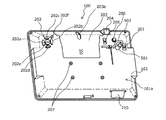
- FIG. 1 is an explanatory view (No. 1) showing an external configuration of a security camera device according to an embodiment of the present invention.
- FIG. 2 is an explanatory view (No. 2) showing an external configuration of the security camera device according to the embodiment of the present invention.
- FIG. 3 is an explanatory view (No. 3) showing an external configuration of the security camera device according to the embodiment of the present invention.
- FIG. 4 is an explanatory view (No. 4) showing an external configuration of the security camera device according to the embodiment of the present invention.
- FIG. 5 is an explanatory diagram (No. 1) showing a connection state between the AC power connector and the power supply plug.
- FIG. 6 is an explanatory diagram (No. 2) showing a connection state between the AC power connector and the power supply plug.
- FIG. 1 is an explanatory view (No. 1) showing an external configuration of a security camera device according to an embodiment of the present invention.
- FIG. 2 is an explanatory view (No. 2) showing an external configuration of the security camera device according
- FIG. 7 is an explanatory diagram showing an installation example of the security camera device according to the embodiment of the present invention.
- FIG. 8 is an explanatory diagram showing an example of the appearance including the display contents of the security camera device according to the embodiment of the present invention.
- FIG. 9 is a block diagram showing an example of the hardware configuration of the security camera device according to the embodiment of the present invention.
- FIG. 10 is a block diagram showing an example of the functional configuration of the security camera device according to the embodiment of the present invention.
- FIG. 11 is an explanatory diagram showing an example of a contact situation of an object.
- FIG. 12 is an explanatory diagram showing a state in which a power supply plug is inserted and removed from the AC power connector.
- FIG. 13 is an explanatory diagram showing an example of a password input screen.
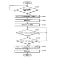
- FIG. 14 is a flowchart showing an example of a processing procedure of the security camera device according to the embodiment of the present invention.
- FIG. 1 shows a front view of the security camera device according to the embodiment of the present invention
- FIG. 2 shows a rear view
- FIG. 3 shows a perspective view from the front side of the security camera device according to the embodiment of the present invention
- FIG. 4 shows a perspective view from the back side.
- the security camera device 100 has a flat plate shape.
- the security camera device 100 includes a housing 101 having a flat rectangular parallelepiped shape, and the housing 101 forms a flat plate shape.
- the security camera device 100 is installed with one surface (hereinafter referred to as “rear surface”) 101a of the flat plate-shaped housing 101 facing the inner wall surface side of the elevator cage (see FIG. 7 described later). In this way, the security camera device 100 can be retrofitted into the basket.
- a display screen (display) 102 is provided on the surface opposite to the back surface 101a (hereinafter referred to as "front surface 101b").
- the display screen 102 can be realized by, for example, a liquid crystal display (LCD: Liquid Crystal Display), an organic EL (Electro-Lumisensence) display, a 7-segment display, or the like.
- the front lens 103 (103a, 103b) is provided on the front 101b.
- the front lens 103a is provided so as to be located vertically below the display screen 102 in the housing 101 when it is installed in the basket.
- the front lens 103b is directed toward the display screen 102 on either the left or right side of the display screen 102 in the housing 101 (in FIGS. 1, 3, and 6). It may be provided so as to be located outside the end of the right).
- the front lens 103 may be provided with only one of 103a and 103b, or both 103a and 103b may be provided. Further, the number of front lenses 103 is not limited to one or two, and may be three or more.
- the front lens 103, together with the front image sensor, constitutes a front camera (see reference numeral 903 in FIG. 9), which is a photographing means according to the present invention.
- the front camera may include one or more lenses between the front lens 103 and the image sensor, a movable mechanism for moving at least one of the plurality of lenses along the optical axis direction, and the like. ..
- the front camera is realized by an AF unit that focuses by a passive method such as contrast AF (AutoFocus) or phase difference AF.
- the front lens 103b is configured to face downward by a predetermined angle with respect to the front plane.
- At least the front lens 103 is located vertically below the display screen 102 in the housing 101, or either the left or right end of the display screen 102 in the housing 101.
- the components other than the front lens 103 are not necessarily located below the display screen 102 in the vertical direction. You may.
- a speaker 104 and a status display LED (Light Emitting Diode) 105 are provided on the front 101b.
- the speaker 104 vibrates the diaphragm by an electric signal which is an audio signal to generate sound.
- the speakers 104 are provided on the left and right sides of the display screen 102 (left and right sides when installed in the basket).
- the speaker 104 may be an output terminal that outputs an audio signal, or an external speaker may be connected to the output terminal to generate sound.
- the number of external speakers to be connected may be one or two or more.
- the installation position of the speaker 104 is not limited to the left and right sides of the display screen.
- the status display LED 105 indicates the operating state of the security camera device 100. Specifically, the status display LED 105 indicates, for example, a power ON / OFF state, a link-up state, the presence / absence of data transmission / reception, the presence / absence of an error, a warning calling attention, and the like.
- the status display LED 105 is composed of a plurality of LED lamps 105a. Each of the plurality of LED lamps 105a may emit light in a different color, or each of the plurality of LED lamps 105a may appropriately switch a plurality of colors to emit light.
- the status display LED 105 indicates the operating state of the security camera device 100 depending on whether or not each LED lamp 105a is lit and the emission color.
- a power button 201 and an operation button 202 are provided on the back surface 101a. Each time the power button 201 is operated, the power of the security camera device 100 is switched ON / OFF.
- the operation button 202 is composed of a plurality of buttons 202a to 202f.
- buttons 202a and 202b accept, for example, an operation for adjusting the volume of the sound output from the speaker 104.
- the buttons 202c and 202d accept, for example, an operation of selecting a desired operation menu from a plurality of operation menus displayed on the setting screen displayed on the display screen 102 when the security camera device 100 is activated.
- Button 202e accepts the decision of the selected operation menu.
- the button 202e may be operated during the activation of the security camera device 100 to accept the operation of switching the display contents on the display screen 102. Specifically, by operating the button 202e while the security camera device 100 is activated, the display content such as an advertisement can be switched to the setting screen.
- the button 202f is operated while the security camera device 100 is activated to accept the start of shooting. Whether to shoot with the front camera or the rear camera can be selected by operating the buttons 202a to 202e.
- At least one of the power button 201 and the operation button 202 may be provided on the back surface 101a.
- the power button 201 may be provided on the back surface 101a
- the operation button 202 may be provided on the side surface (the surface other than the back surface 101a and the front surface 101b) or the front surface 101b of the housing 101.
- the operation button 202 may be realized by stacking a touch panel on the display screen 102 and using soft keys reproduced by software by the touch panel and the image displayed on the display screen 102.
- the back surface 101a is provided with a back cover 203, a back lens 204, a power switch 205 for a port, an external antenna mounting hole 206, a plurality of screw holes 207, an AC power connector 208, and an AC power cable fixing member 209. ing.
- the back cover 203 is detachably attached to the housing 101.
- the back cover 203 is fixed to the housing 101 using screws or the like.
- the screw for fixing the back cover 203 to the housing 101 it is preferable to use a special screw that cannot be operated with a general-purpose tool. Further, it is preferable that the back cover 203 is provided at a plurality of locations including at least two locations on both sides.
- the back cover 203 covers the ports and slots provided on the back 101a (both not shown) when attached to the housing 101.
- the port is responsible for inputting / outputting data to / from the outside of the security camera device 100, and can be specifically realized by, for example, a USB Type-A port.
- a plurality of ports may be provided.
- one is used as an interface with an external device such as a remote monitoring device for an elevator, and the other is a USB memory that records (records) the image in the basket taken by the security camera function. It can be used as an interface with the storage device of. As a result, it is possible to record (record) the image in the basket while operating in cooperation with the external device.
- the slot accepts the insertion of an expansion board, a memory card, or the like, and can be specifically realized by, for example, a SIM card slot or a MicroSD card slot.
- the back cover 203 is provided with a slit 203a.
- the cable (see reference numeral 502 in FIGS. 5 and 6) connecting the security camera device 100 and the external device via the port is externally connected from the slit 203a. Can be pulled out to. As a result, the degree of freedom of connection with the external device can be ensured.
- the rear lens 204 together with the rear image sensor, constitutes a rear camera (see reference numeral 904 in FIG. 9).
- the rear camera is used to read the property code (not shown) attached to the elevator to be installed when the security camera device 100 is installed.
- the property code can be realized by, for example, a two-dimensional code attached to the inner wall surface of the elevator car.
- the two-dimensional code may be read by the rear camera only when the security camera device 100 is installed, or may be read periodically after the installation or when predetermined conditions are met.
- the port power switch 205 switches the port power ON / OFF by being operated. As a result, power saving can be achieved by turning off the power when the port is not used.
- a port power switch 205 may be provided for each port. As a result, the power can be switched on / off for each port, and further power saving can be achieved.
- the external antenna mounting hole 206 is used for mounting an external antenna that is separate from the security camera device 100.
- the external antenna mounting hole 206 can be realized by, for example, an F-type connector.
- the F-type connector is connected to a receiving circuit (not shown) inside the housing 101.
- a screw for fixing the security camera device 100 to the inner wall surface of the basket is screwed into the screw hole 207.
- the security camera device 100 may be directly fixed to the inner wall surface of the basket by a screw, or may be fixed to the inner wall surface of the basket via a stay fixed to the inner wall surface of the basket. Good.
- the AC power connector 208 has a power supply plug (see reference numeral 501 in FIGS. 5 and 6) that can be inserted and removed, and receives power supply by inserting the power supply plug connected to the power supply.
- the AC power connector 208 accepts the insertion of a power supply plug included in a device called an AC (Alternating Current) adapter or the like, which is provided with a device that extracts a predetermined DC power from an alternating current input from an AC power supply (commercial power supply).
- the AC power connector 208 realizes the power connector according to the present invention.
- the power supply plug is connected to the AC power supply and is connected to the main body composed of a transformer circuit, a rectifying circuit, a regulated power supply circuit, etc. that extract a predetermined DC power from the AC power supply.
- the security camera device 100 By receiving power via the AC adapter, the security camera device 100 itself, which operates using a semiconductor element, can operate even if it is not equipped with a circuit that converts alternating current into direct current. As a result, the weight and cost of the security camera device 100 can be reduced.
- the security camera device 100 itself may include a circuit that converts alternating current into direct current.
- the AC adapter is not limited to the one that is normally connected to the AC power supply, and may include an outlet plug that receives power by being inserted into an outlet.
- the AC power cable fixing member 209 is used to fix the position of the cable continuous with the power supply plug inserted (connected) to the AC power connector 208.
- the AC power cable fixing member 209 has an arc shape in which both ends in the length direction are in contact with the back surface 101a, and a hole is formed by the arcuate inner peripheral surface and the back surface 101a.
- At least one end of the AC power cable fixing member 209 in the length direction is fixed to the back surface 101a.
- the other end of the AC power cable fixing member 209 in the length direction may not be fixed to the back surface 101a or may be separated from the back surface 101a. The method of fixing the cable using the AC power cable fixing member 209 will be described later (see FIGS. 5 and 6).
- Another port is provided at the lower part of the housing 101.
- Another port is responsible for inputting and outputting data to and from the outside of the security camera device 100, and specifically, for example, like the above port, it can be realized by a USB Type-A port.
- Another port is used, for example, when exporting the image data (recorded data of the security camera) taken by the security camera device 100 to the external device.
- the image data can be exported to the external device without removing the security camera device 100 from the inner wall surface of the basket or the back cover 203 from the housing 101. Can be done.
- the housing 101 may be provided with a cover 210 that covers another port.
- the cover 210 may be fixed to the housing 101 using screws or the like.
- As the screw for fixing the cover 210 it is preferable to use a special screw as well as the screw for fixing the back cover 203 described above. As a result, it is possible to prevent the image data from being illegally exported even when the port is provided in the lower part of the housing 101 in order to ensure good operability.
- FIGS. 5 and 6 are explanatory views showing a connection state between the AC power connector 208 and the power supply plug.
- the security camera device 100 can be powered and operated by inserting (connecting) a power supply plug 501 connected to the AC power supply into the AC power supply connector 208. ..
- the cable 502 connected to the power supply plug 501 for example, after inserting (connecting) the power supply plug 501 into the AC power connector 208, consideration is given to preventing disconnection of the cable 502 and preventing interference with surrounding members. Route it to any position. Then, after confirming that the routed cable 502 does not break and that the cable 502 does not interfere with surrounding members, the cable 502 is fixed to the AC power cable fixing member 209 using a binding band or the like. To do.
- the positional relationship between the AC power connector 208 and the power supply plug 501 is fixed to some extent, the free movement of the power supply plug 501 with respect to the AC power connector 208 is suppressed, and the elevator basket moves up and down. It is possible to prevent the power supply from being inadvertently stopped due to vibration or the like. Further, by fixing the position of the cable 502, it is possible to prevent mischief such as the cable 502 hanging down and spoiling the aesthetic appearance, or pulling the cable 502 to stop the power supply.
- FIG. 7 is an explanatory diagram showing an installation example of the security camera device 100 according to the embodiment of the present invention.
- FIG. 7 shows the inside of the elevator basket.
- the elevator car 701 is provided with a space for the occupant to ride inside, opens and closes the space and the outside, and is provided with a door 702 at the entrance / exit portion where the occupant enters and exits the basket 701.
- An operation panel 703 operated by an occupant on the basket 701 is provided on the inner wall surface of the basket 701.
- the operation panel 703 includes, for example, a group of operation buttons including a destination floor button, a door open / close button, an emergency button, and a display for displaying the floor on which the basket 701 is located.
- the operation panel 703 is an inner surface of the basket 701 and is provided on the same surface as the door 702.
- the security camera device 100 is the same wall surface as the wall surface on which the door 702 and the operation panel 703 are provided, and is installed near the ceiling above the operation panel 703. This assumes that the occupants in the basket 701 generally stand facing the wall surface on the door 702 side.
- the occupant in the basket 701 can display the display.
- the advertisement displayed on the screen 102 can be easily seen. As a result, a high advertising effect can be exhibited through the security camera device 100.
- the security camera device 100 captures the facial expressions of the occupants with, for example, a front camera. By installing the security camera device 100 near the ceiling, the facial expressions of the occupants can be easily photographed by the front camera. In addition, the front camera can capture the facial expressions of the occupants when getting out of the basket 701.
- the security camera device 100 by installing the security camera device 100 near the ceiling, the occupant cannot easily touch the security camera device 100 even if he / she reaches out in a normal state. Therefore, it is possible to prevent the occupant from inadvertently touching, illegally operating, or destroying the security camera device 100.
- the security camera device 100 may be provided on the wall surface (the wall surface on the back side of the basket 701) facing the wall surface on which the door 702 and the operation panel 703 are provided. By providing it on the wall surface on the back side of the basket 701, the occupant can see the security camera device 100 (display screen 102) when entering the basket 701.
- the security camera device 100 on the wall surface on which the door 702 and the operation panel 703 are provided and the wall surface facing the wall surface (the wall surface on the back side of the basket 701), the occupant can be inside the basket 701.
- the security camera device 100 (display screen 102) can be seen when entering and exiting the basket 701.
- the security camera device 100 may be provided on the side wall surface instead of the upper side of the same wall surface as the wall surface on which the door 702 and the operation panel 703 are provided. In this case, it is preferable that the security camera device 100 is provided at an upper position close to the ceiling on the side wall surface of the basket 701. Further, the security camera device 100 may be installed at a corner position in the corner of the basket 701. As described above, the security camera device 100 may be installed at any position above the upper end of the door 702 in the basket 701.
- the security camera device 100 can be retrofitted after the elevator is installed.
- the security camera device 100 includes the size of the basket 701 (capacity), the height of the ceiling of the basket 701, the shape of the basket 701 (the floor is square or rectangular, etc.), the type of elevator (see-through type, with or without a mirror on the wall surface). ), The type of outer door (with or without windows), etc. can be taken into consideration when installing in the optimum position. Further, the security camera device 100 may be capable of freely changing its installation position after the security camera device 100 is installed.
- the security camera device 100 can be installed, for example, by screwing it to the wall surface. By screwing the security camera device 100 to the wall surface, it is possible to reliably prevent the device from falling.
- the screwing may be applied not only to the wall surface but also to the ceiling of the basket 701 via a stay or the like.
- the security camera device 100 may be installed by a method other than screwing (for example, using a magnet or the like).
- the basket 701 is provided with a plug socket 704 that accepts the insertion of the outlet plug included in the AC adapter.
- the plug socket 704 constitutes a wiring plug connector together with the outlet plug by inserting the outlet plug provided in the AC adapter.
- an A type plug socket widely used in Japan can be used.
- the plug socket 704 is not limited to the A type. Specifically, for example, a B3 type or C type plug socket widely used in India or Indonesia may be used, or a BF type plug socket widely used in Hong Kong or the like may be used.
- an SE type plug socket widely used in South Korea or the like may be used, or an O type plug socket widely used in Taiwan or the like may be used.
- elevators are installed from various types such as A type, B type, C type, B3 type, BF type, SE type, and O type. It is preferable to use any type of plug socket according to the area where it is used.
- the plug socket 704 is electrically connected to the electric circuit of the board housed in the box on the basket. As a result, power can be supplied to the security camera device 100 via the plug socket 704 and the AC adapter.
- the plug socket 704 is not limited to the one directly connected to the terminal of the electric circuit of the board housed in the box on the basket, and may be connected to the power line connected to the terminal. When connecting the plug socket 704 to such a power line, a branching connector can be provided on the power line, and the plug socket 704 can be connected to the connector.
- the security camera device 100 does not have to make a separate hole for inserting the power supply cable 502 into the basket 701. Can be powered.
- the security camera device 100 can be easily and quickly installed without imposing a burden on the operator, and can be always operated without being stopped due to insufficient power. Further, even when an advertisement or the like is displayed on the display screen, it can be operated stably without being stopped due to insufficient power.
- the work time required for installing the security camera device 100 can be shortened, and the burden on elevator users and workers can be reduced.
- the basket 701 is provided with the plug socket 704, it is not necessary to backfill the through hole for inserting the power supply cable 502 into the basket 701, and the burden on the operator for the removal work is reduced. be able to. Further, it is possible to secure the aesthetic appearance in the basket 701 after the security camera device 100 is removed.
- the plug socket 704 When the plug socket 704 is exposed in the basket 701, it is preferable that the plug socket 704 is arranged at a high position in the basket 701 as shown in FIG. 7. Specifically, as shown in FIG. 7, the plug socket 704 is preferably provided on the side surface or the ceiling surface of the basket 701. By arranging the plug socket 704 exposed in the basket 701 at a high position in the basket 701 in this way, it is possible to prevent water droplets flying from the umbrella or clothes from adhering in rainy weather, and it is possible to prevent electric power theft or children. It can make mischief less likely.
- One plug socket 704 may be provided in one basket 701, or a plurality of plug sockets 704 may be provided in one basket 701.
- the plurality of plug sockets 704 may be arranged side by side or dispersed in a plurality of places.
- the plug socket 704 may be arranged, for example, so that the plug socket 704 is located on the same surface as the inner wall surface (ceiling surface) of the basket 701.
- the basket 701 may be provided with a plug seat, which is not shown, instead of the plug socket 704.
- the plug seat has a function of supplying power supplied from an electric circuit housed in a box on a basket (not shown) to the security camera device 100 connected to the plug seat.
- the resectorable may include wiring for signal transmission in addition to wiring for power supply.
- the resectorable that realizes the plug seat is preferably realized by a hot plug that can be inserted and removed during the operation of the security camera device 100 connected to the resectorable.
- the resectorable that realizes the plug seat may further supply power to the security camera device 100 via a control circuit (not shown).
- the plug seat may be realized by, for example, a USB connector.
- the USB connector as a resectorable that realizes the plug seat can be realized by resectorable of various known USB connectors such as a USB Type-A connector, a Micro USB connector, a Micro USB Type-B connector, and a USB Type-C connector. Can be done.
- the resectorable that realizes the plug seat is not limited to the USB interface connector (resectorable), for example, IEEE 1394 connector, PS / 2 connector, D-Sub connector, DIN connector, coaxial connector, and various other known connectors. It may be realized by the connector for communication of.
- One resectorable that realizes the plug seat may be provided in one basket 701, or a plurality of resectors may be provided in one basket 701.
- the number of types of communication I / F connectors may be one type or a plurality of types.
- the resectorable that realizes the plug seat can be arranged, for example, so that the end portion of the resectorable is located on the same surface as the inner wall surface of the basket 701. Further, the resectorable that realizes the plug seat may, for example, have the end portion of the resectorable protruding from the inner wall surface of the basket 701 to the inside of the basket 701, and is arranged at a position recessed from the inner wall surface of the basket 701. May be good.
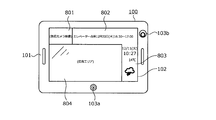
- FIG. 8 is an explanatory diagram showing an example of the appearance including the display contents of the security camera device according to the embodiment of the present invention.
- the display screen 102 of the security camera device 100 forms a long rectangle in the lateral direction and is surrounded by the housing 101.
- the display screen 102 can be displayed from a plurality of areas (four in this embodiment) such as a security camera image display area 801, a management information display area 802, various information display areas 803, and an advertisement display area (advertisement area) 804. It may be configured. In this way, by dividing the display into four areas and displaying the information, various information can be efficiently transmitted to the occupants.
- a security camera image display area 801, a management information display area 802, and various information display areas 803 are provided in an inverted "L" shape from the upper side to the right side so as to surround the rectangular advertisement display area 804 on the lower left side of the display screen 102.
- the security camera image display area 801 is provided on the left side, and subsequently, the management information display area 802 is provided horizontally. In the security camera image display area 801, the image taken by the front camera may be displayed in real time.
- this management information display area 802 if the message is long, the message is displayed so as to flow from the right side to the left side.
- the management information display area 802 is provided on the upper side of the display screen 102 so that the upper side of the display screen 102 is easily visible to the occupant, and therefore relatively important management information can be reliably transmitted to the occupant.
- various information display areas 803 are provided vertically on the right side surface to display various information to be notified to elevator occupants, such as weather forecasts, traffic information, and news as shown in FIG.
- various information display areas 803 when displaying a large amount of information, it may be displayed so as to flow from the lower side to the upper side.
- the information for the new region when displaying the weather forecast for each region, the information for the new region may be displayed sequentially from the bottom, and the information for the old region may be moved upward and then deleted. On the contrary, it may be displayed so as to flow from the upper side to the lower side. Further, it may be displayed so as to flow to either the left or right.
- the display form can be changed depending on the content of the information to be displayed.
- the management information display area 802 can be lengthened to the right side, and various information display areas 803 can be lengthened to the upper side according to the display situation. Further, depending on the information to be displayed, the management information display area 802 and various information display areas 803 can be used as a series.
- the display screen 102 By laying out the display screen 102 in this way, it is possible to display the advertisement information and at the same time convey other information to the occupants.
- the display screen 102 usually has a layout as shown in FIG. 8, but this layout may be changed depending on the situation. For example, in the event of an emergency such as an elevator failure, the advertising area may be erased to display the required information. Further, as an advertisement display effect, the entire surface of the display screen 102 may be used as an advertisement display.
- FIG. 9 is a block diagram showing an example of the hardware configuration of the security camera device 100 according to the embodiment of the present invention.
- the security camera device 100 includes a CPU (Central Processing Unit) 901, a memory 902, a front camera 903, a rear camera 904, a communication interface (I / F) 905, and a display screen (display). ) 102, a speaker 104, a microphone 906, a vibration sensor 907, an illuminance sensor 908, a contact sensor 909, a power control unit 910, a power button 201, and an operation button 202.
- Each component 102, 104, 201, 202, 901 to 910 is connected by a bus 900.
- the security camera device 100 includes tablet terminal devices (tablet terminals, tablet PCs), smartphones, notebook personal computers (mobile PCs), which include each component 102, 104, 201, 202, 901 to 910. It may be realized by using an information processing device such as a digital camera. In this way, an all-in-one, portable and portable information processing device that integrates multiple functions can be used as a security camera device. As a result, the security camera device 100 can be realized by a general-purpose device without separately developing and manufacturing a device dedicated to the elevator.
- the CPU 901 controls the entire device of the security camera device 100 by executing the program stored in the memory 902.
- the memory 902 can store various information including a program executed by the CPU 901. Further, the memory 902 may store advertisement information displayed on the display screen 102, image data captured by the front camera 903 and the rear camera 904, information regarding the date and time of capture, and the like.
- the memory 902 may be an internal memory built in the security camera device 100, for example, a hard disk memory, an IC memory, an SSD (Solid State Drive), or the like.
- the memory 902 may be a memory card that can be attached to and detached from the security camera device 100 via a card slot provided in the security camera device 100.
- the function of the memory card can be realized by, for example, an IC card such as an SD (Secure Digital) memory card.
- the memory card may realize its function by an external hard disk, a USB memory, an SSD, or the like.
- the front camera 903 includes a front image sensor, and acquires image information (photographed data) by converting the light received by the front image sensor through the front lens 103 into an electric signal.
- the front camera 903 may capture a still image or may capture a moving image.
- the moving image includes a continuous reproduction of still images taken at predetermined time intervals.
- the image information may be compressed by a standard of a predetermined video / audio data compression method (for example, MPEG (Moving Picture Experts Group) or the like).
- the rear camera 904 includes a rear image sensor, and acquires image information (photographed data) by converting the light received by the rear image sensor through the rear lens 204 into an electric signal.
- the rear camera 904 captures, for example, a still image.
- the image information may be compressed by a standard of a predetermined video / audio data compression method (for example, MPEG (Moving Picture Experts Group) or the like).
- the communication I / F905 is an interface for connecting the security camera device 100 and a network N such as the Internet through a communication line, controls the interface between the network N and the inside of the security camera device 100, and inputs data from an external device. And control the output of data to external devices.
- the CPU 901 may control the communication I / F 905 to acquire advertisement information from an advertisement distribution server or an advertiser's information terminal device (not shown) via the network N. Further, the CPU 901 may control the communication I / F905 to receive advertisement information from an information terminal device such as a smartphone carried by an elevator occupant.
- Communication I / F905 is, for example, a wireless interface using Wi-Fi (registered trademark). Further, the communication I / F905 may be a wireless communication interface such as a mobile phone line (for example, LTE (Long Term Evolution)) or PHS (Personal Handy-phone System), or may be a wired interface such as a modem or a LAN adapter. A communication interface can be adopted. Further, the elevator may be connected to a network provided for remote monitoring or the like, and information may be transmitted / received via the network. Further, the communication I / F905 may be realized by, for example, a USB interface.
- the display screen 102 is driven and controlled by the CPU 901 to display an advertisement or the like.
- the display screen 102 may display elevator management information such as a maintenance schedule.
- the management information is appropriately transmitted to the security camera device 100 by, for example, the administrator of the security camera device 100.
- the advertisement information and the management information may include information indicating a period (display start date and time, display end date and time, etc.) to be displayed on the display screen 102.
- the speaker 104 vibrates the diaphragm with an electric signal which is an audio signal to generate sound. Further, the speaker 104 may be an output terminal that outputs an audio signal, and an external speaker 104 may be connected to the output terminal to generate sound.
- the microphone 906 collects the sound in the basket 701.
- the vibration sensor 907 detects the vibration of the basket 701.
- the vibration sensor 907 can be realized by, for example, an acceleration sensor or the like.
- the illuminance sensor 908 detects the illuminance (brightness) in the basket 701.
- the illuminance sensor 908 can be realized by using, for example, a phototransistor or a photodiode.
- the contact sensor 909 detects, for example, that an object has come into contact with the surface of its own device (security camera device 100) including the display screen 102.
- the contact sensor 909 uses, for example, a resistance film method (a method of detecting by measuring a voltage change due to contact) and a capacitance method (a method of detecting a change in capacitance (charge), which is a weak current generated when contact is made).
- Sensor detection method ultrasonic method (method of detecting contact by attenuation of surface acoustic waves of ultrasonic waves), optical method (method of detecting contact by blocking infrared light using an infrared image sensor, etc.)
- Contact can be detected by a method such as).
- sensors such as an proximity sensor, a temperature sensor, and a humidity sensor may be provided.
- the power supply control unit 910 can be realized by, for example, a voltage adjusting unit (power supply IC or the like) that adjusts the voltage of the AC power supply supplied via the cable 502.
- the power control unit may be, for example, a transformer circuit, a rectifying circuit, or a stabilized power supply that extracts predetermined DC power from an outlet plug, a cable connected to the outlet plug, and an AC power supply supplied via the outlet plug. It may be configured by a circuit or the like.
- the security camera device 100 further includes a battery (storage battery) such as a lithium battery.
- the power supply control unit 910 may include a storage battery.
- the power control unit 910 may include a connection terminal for connecting a storage battery. As a result, the storage battery can be easily replaced.
- the power supply control unit 910 has the AC power supply connector 208, and supplies the power supplied to the AC power supply connector 208 to each component of the security camera device 100.
- the power button 201 or the operation button 202 Each time the power button 201 or the operation button 202 receives an operation, the power button 201 or the operation button 202 outputs a signal corresponding to the received button to the CPU 901.
- the CPU 901 drives and controls each unit based on the signals output from the power button 201 and the operation button 202 to switch the power ON / OFF, adjust the volume of the sound output from the speaker 104, and display the display screen.
- the display content in 102 is switched.
- the security camera device 100 may include a memory card I / F, an input / output device, a GNSS receiver, and the like.
- the memory card I / F is an interface connected to the security camera device 100 via the card slot.
- the memory card I / F controls the internal interface between the memory card and controls the input of data from the memory card and the output of data to the memory card.
- the input / output device can be realized by, for example, a key or a button for inputting characters, numbers, various instructions, and the like. Further, the input / output device may be realized by a microphone, a display (touch panel), a connection terminal to which another information processing device can be connected, or the like.
- GNSS Global Positioning Satellite System
- the GNSS receiver receives radio waves from three or five artificial satellites, receives radio waves from the artificial satellites, and outputs GNSS positioning data in order to obtain a geometric position with the artificial satellites.
- the current position of the security camera device 100 can be grasped by the GNSS receiver.
- the current position may be, for example, information about latitude and longitude. Further, the current position may be information about a base station performing wireless communication. When using the information about the base station as the current position, it is not necessary to use the GNSS receiver.
- FIG. 10 is a block diagram showing an example of the functional configuration of the security camera device according to the embodiment of the present invention.
- the security camera device 100 includes a control unit 1000, a photographing unit 1001, a photographing information storage unit 1002, a power supply unit 1003, a power storage unit 1004, a power supply monitoring unit 1005, and a power supply control unit 1006.
- arrows A to E indicate the flow of power supply.
- the control unit 1000 controls the entire security camera device 100. Specifically, the control unit 1000 can realize its function by, for example, the CPU 901 shown in FIG. 9 executing a program stored in the memory 902 or the like.
- the photographing unit 1001 photographs the inside of the basket 701.
- the photographing unit 1001 can realize its function by, for example, the front camera 903 shown in FIG. 9, that is, the front lenses 103 (103a, 103b) and the like.
- the shooting information storage unit 1002 stores image information and video information shot by the shooting unit 1001. Specifically, the shooting information storage unit 1002 can realize its function by, for example, the memory 902 shown in FIG. Further, the photographing information storage unit 1002 may realize its function by an external memory or the like (not shown). Further, the image information stored in the photographing information storage unit 1002 may be transmitted to an external device such as a management center via the network N by using the communication I / F905 shown in FIG.
- the power supply unit 1003 receives power (from the AC power connector 208) via the power supply plug 501 that supplies power to drive its own device (security camera device 100) including the photographing unit 1001 (arrow). A and arrow B), the received power is supplied to the own device (security camera device 100) (arrow C). Here, the arrow C is shown so as to supply power to the control unit 1000. This indicates that power is supplied to each component of the own device (security camera device 100) by supplying power to the control unit 1000 (the same applies to the arrow E described later). ..
- the power supply unit 1003 also supplies power to the power storage unit 1004 (arrow D).
- the power supply unit 1003 can realize its function by, for example, the power supply control unit 910 shown in FIG. Further, the power supply unit 1003 may realize the function by the CPU 901 executing the program stored in the memory 902 or the like.
- the power storage unit 1004 is provided in its own device (security camera device 100), and power is supplied by the power supply unit 1003 (arrow D) to store power. Specifically, the power storage unit 1004 can realize its function by, for example, the power supply control unit 910 shown in FIG.
- the power supply monitoring unit 1005 monitors the status of the power supply received by the power supply unit 1003.
- the power supply status is, for example, a situation in which the voltage of the power supply (arrow B) received by the power supply unit 1003 suddenly changes or the voltage becomes unstable.
- 1003 is in a situation where stable power cannot be supplied to each part of its own device (security camera device 100) including the photographing unit 1001. This corresponds to the case where the photographing by the photographing unit 1001 is hindered.
- the power supply monitoring unit 1005 detects that the supply (arrow A, arrow B) to the power supply unit 1003 via the power supply plug 501 has stopped.
- the power supply monitoring unit 1005 monitors the state of insertion / removal of the power supply plug 501 with respect to the AC power connector 208 into which the power supply plug 501 can be inserted / removed. In addition, the power supply monitoring unit 1005 monitors the state of the amount of electricity stored in the electricity storage unit 1004.
- the power supply monitoring unit 1005 can realize its function by, for example, the power supply control unit 910 shown in FIG. Further, the power supply monitoring unit 1005 may realize the function by the CPU 901 executing a program stored in the memory 902 or the like.
- the status of power supply monitoring by the power supply monitoring unit 1005, specifically, for example, the power supply unit 1003 supplies stable power to each part of its own device (security camera device 100) including the photographing unit 1001.
- the power supply (arrow C) from the power supply unit 1003 to the own device (security camera device 100) is switched to the supply (arrow E) from the power storage unit 1004.
- the power supply control unit 1006 detects that the power supply monitoring unit 1005 has stopped receiving the power supply unit 1003 (arrow B)
- the power supply control unit 1003 sends the power supply unit 1003 to its own device (security camera device 100).
- the power supply (arrow C) of the above may be switched to the supply (arrow E) from the power storage unit 1004.
- the suspension of receiving power to the power supply unit 1003 includes causes such as a power failure of the elevator, disconnection of the cable 502, and poor contact (cause that the supply of arrow A cannot be performed).
- the power supply control unit 1006 detects that the power supply plug 501 has been pulled out from the AC power connector 208 as a result of monitoring by the power supply monitoring unit 1005, the power supply control unit 1006 has its own device (security) from the power supply unit 1003.
- the supply of power to the camera device 100) (arrow C) may be switched to the supply from the power storage unit 1004 (arrow E).
- the power supply control unit 1006 detects that the power supply plug 501 has been inserted into the AC power connector 208 by the power supply monitoring unit 1005, the power supply control unit 1006 sends the power storage unit 1004 to its own device (security camera device 100).
- the power supply (arrow E) of the above may be switched to the supply (arrow C) from the power supply unit 1003.
- the supply of power (storage, arrow D) from the power supply unit 1003 to the power storage unit 1004 may be restarted.
- the power supply control unit 1006 may stop the supply of power to the display unit 1009 according to the state of the amount of electricity stored in the power storage unit 1004.
- the state of the amount of electricity stored in the electricity storage unit 1004 may be based on, for example, the monitoring result of the monitoring of the power supply monitoring unit 1005.
- the power supply control unit 1006 can realize its function by, for example, the CPU 901 shown in FIG. 9 executing a program stored in the memory 902 or the like. Further, the power supply control unit 1006 may realize the function by the CPU 901 executing the program stored in the memory 902 or the like.
- Advertisement information receiving unit 1007 receives advertisement information related to advertisements for elevator occupants. Specifically, the advertisement information receiving unit 1007 can realize its function by, for example, the communication I / F905 shown in FIG. The advertisement information receiving unit 1007 can receive advertisement information from an advertisement distribution server or an advertiser's information terminal device (not shown) via the network N. Further, the advertisement information receiving unit 1007 may receive the advertisement information from the information terminal device described later provided by the occupant of the elevator.
- the advertisement information storage unit 1008 stores the advertisement information received by the advertisement information reception unit 1007. Specifically, the advertisement information storage unit 1008 can realize its function by, for example, the memory 902 shown in FIG.
- the advertisement information storage unit 1008 may store the advertisement information received by the advertisement information receiving unit 1007 as it is, or the advertisement information once received by the advertisement information receiving unit 1007 may be displayed by the control unit 1000 for display. You may try to memorize the processed one.
- the display unit 1009 is composed of an advertisement information display control unit 1010 and a display screen 102.
- the display screen 102 is provided in front of the security camera device 100, and displays an advertisement in the basket 701 to the occupants of the basket 701.
- the advertisement information display control unit 1010 displays an advertisement on the display screen 102 based on the advertisement information received by the advertisement information receiving unit 1007 and stored in the advertisement information storage unit 1008. Further, the advertisement information display control unit 1010 may display information other than the advertisement on the display screen 102. Specifically, the advertisement information display control unit 1010 can realize its function by, for example, the CPU 901 shown in FIG. 9 executing a program stored in the memory 902 or the like.
- the advertisement information display control unit 1010 may display the advertisement information stored in the advertisement information storage unit 1008 on the display screen 102, and the control unit 1000 may display the advertisement information stored in the advertisement information storage unit 1008 on the display screen 102. After being processed by, it may be displayed on the display screen 102.
- the detection unit 1011 detects that an object has come into contact with its own device (security camera device 100) including the photographing unit 1001 and the display unit 1009. At that time, the detection unit 1011 determines the status of the functional failure of its own device (security camera device 100) (for example, power supply abnormality, display failure of the display screen 102, posture abnormality of its own device (security camera device 100), camera 903. , The failure of the captured image by the 904, the failure of the sound collection by the microphone 906, and the like, the failure caused by the contact of the object may be detected. Further, the degree of the failure may be detected. , Detected, or analyzed.
- the detection unit 1011 realizes its function by, for example, the contact sensor 909 or another sensor shown in FIG. 9, or by the CPU 901 executing a program stored in the memory 902 or the like. be able to. Further, the detection unit 1011 does not detect by one sensor (for example, contact sensor 909), but includes the contact sensor 909, or the object is based on the detection by a plurality of sensors excluding the contact sensor 900. It may be made to detect the contact with the security camera device 100).
- the detection unit 1011 realizes its function by, for example, the contact sensor 909 or another sensor shown in FIG. 9, or by the CPU 901 executing a program stored in the memory 902 or the like. be able to. Further, the detection unit 1011 does not detect by one sensor (for example, contact sensor 909), but includes the contact sensor 909, or the object is based on the detection by a plurality of sensors excluding the contact sensor 900. It may be made to detect the contact with the security camera device 100).
- the object that the detection unit 1011 detects contact with its own device may be an object, specifically, a baggage that is carried in or out of the basket.
- the own device security camera device 100
- the own device is attached at a position higher than the height of a person. Therefore, normally, when the occupant gets on and off, the human body does not come into contact with the own device (security camera device 100).
- the carrier may accidentally hit the load against its own device (security camera device 100) as shown in FIG. 11 to be described later.
- the object that the detection unit 1011 detects contact with the own device may be a human body, specifically, for example, a human hand or finger, or another part of the human body. ..
- a human hand or finger or another part of the human body. ..
- a tool held in the hand for example, a screwdriver. Therefore, if it can be detected that a human hand has touched or a tool has touched, it is easy that the security camera device 100 is about to be removed or that the security camera device 100 is about to be mischievous. Can be judged.
- the display unit 1009 (advertisement information display control unit 1010) that controls the display screen 102 and displays an advertisement to the occupant of the basket is, for example, own device (security camera) based on the detection result by the detection unit 1011.
- a password input screen (for example, the password input screen 1300 of FIG. 13 described later) is displayed on the display screen 102.
- the display unit 1009 controls the advertisement information display control unit 1010 to erase the contents displayed on the display screen 102 until then, and instead displays the password input screen. May be good.
- the password input screen may be displayed together with the contents displayed on the display screen 102 until then, or instead of a part of the contents displayed on the display screen 102 until then. The contents of the password input screen will be described in detail with reference to FIG. 13, which will be described later.
- the display unit 1009 may continue to display the password input screen displayed on the display screen 102 without erasing it, unless a valid password is input. Further, after the password input screen is once displayed, the display unit 1009 displays the password input screen without erasing it even if the power is turned off and reset, unless a valid password is input. You may keep doing it. In this way, it is possible to prevent a person who does not know the password from clearing the password input screen. If the password input screen is not erased, the display of the password input screen is obstructed, another display screen cannot be displayed on the display screen 102, and the function as a display device cannot be fully realized.
- the own device security camera device 100
- the function as the tablet terminal device cannot be fully exhibited unless the password input screen is erased, and it is difficult to reuse it. Therefore, even if it is stolen, its value as a target for resale is low.
- the alarm output unit 1012 outputs an alarm when the password input screen is displayed on the display screen 102 by the display unit 1009. Specifically, when the detection unit 1011 detects the contact of an object, it outputs an alarm. Specifically, the alarm output unit 1012 can realize its function by, for example, the CPU 901 shown in FIG. 9 executing a program stored in the memory 902 or the like. The alarm output unit 1012 outputs a warning sound or a predetermined sound from the voice output unit 1013.
- the audio output unit 1013 can realize its function by, for example, the speaker 104 shown in FIGS. 1, 3, 9, and the like.
- the warning sound may be an alarm, a siren, or the like.
- the predetermined voice may be, for example, characters on the password input screen displayed on the display screen 102, or another word (for example, "A contact has been detected. Please contact the management center immediately.” . ”) And so on.
- the alarm output unit 1012 outputs an alarm by turning on or blinking a light (lamp) provided in the security camera device 100 or separately attached, which is not shown. It may be.
- the carrier Since the alarm is output in this way, it can be expected that the thief will be surprised at this alarm and give up taking away his own device (security camera device 100).
- the package carrier since the package carrier may not be aware that the package has hit the own device (security camera device 100), the carrier can be made aware of it by outputting an alarm.
- the transmission unit 1013 transmits the shooting information to a predetermined server via the network.
- a given server includes, for example, a management center server.
- the identification information may be transmitted, for example, by uploading to a predetermined server via the network N.
- the transmission unit 1013 can realize its function by, for example, the communication I / F905 shown in FIG. Further, the transmission unit 1013 may realize the function by the CPU 901 executing a program stored in the memory 902 or the like.
- the reception unit 1011 accepts the password input.
- the password should only be known to workers who have the authority to unlock it (for example, elevator maintenance managers or building managers).
- the reception unit 1011 can realize its function by, for example, the power button 201, the operation button 202, the communication I / F905, and the like shown in FIG. Further, the reception unit 1011 may realize the function by the CPU 901 executing the program stored in the memory 902 or the like.
- the password can be entered by operating the operation button 202 of the own device (security camera device 100) or the touch panel provided on the display screen 102. At that time, for example, a soft keyboard or the like is displayed on the display screen 102. Further, the password may be input from an external device (not shown) by remote control using wireless communication.
- a two-dimensional code (for example, bar code, QR code (registered trademark)) containing information about the password displayed on the smartphone or tablet terminal of a worker who has the authority to unlock can be used as a front camera or a rear camera. You may enter the password by reading it into. Alternatively, a worker who has the authority to unlock the lock may be photographed, and the password may be input by various authentication processes such as biometric authentication of the worker's face and gesture authentication. In that case, specifically, the reception unit 1011 performs its function by, for example, the front camera 903 or the rear camera 904 and the CPU 901 shown in FIG. 9 executing a program stored in the memory 902 or the like. It can be realized.
- a two-dimensional code for example, bar code, QR code (registered trademark)
- QR code registered trademark
- a worker who has the authority to unlock the password may be made to utter a password, and the voice (content of words, voiceprint, etc.) may be recognized and processed to replace the password input.
- the reception unit 1011 can realize its function by, for example, the microphone 906 and the CPU 901 shown in FIG. 9 executing a program stored in the memory 902 or the like. ..
- the display unit 1009 displays the password displayed on the display screen 102.
- the input screen may be erased.
- the state before displaying the password input screen may be restored.
- the display of the advertisement on the display screen 102 may be restarted.
- the suspended advertisement may be resumed, or an advertisement different from the suspended advertisement may be displayed.
- the transmission unit 1015 provides notification information indicating that an object has come into contact with the own device (security camera device 100) and a password input screen is displayed on the display screen 102, for example, identification of the own device (security camera device 100).
- Information, information on the date and time of occurrence that is, the date and time when the password input screen 1300 is displayed), and the like are transmitted to a predetermined server via the network N shown in FIG.
- video information at a predetermined time before and after the occurrence date and time may also be transmitted. This makes it possible to analyze the cause of the contact.
- the transmission unit 1012 can realize its function by, for example, the communication I / F905 shown in FIG. Further, the transmission unit 1012 may realize the function by the CPU 901 executing a program stored in the memory 902 or the like.
- the identification information transmitted by the transmission unit 1015 may be an ID number unique to the security camera device 100 or the like, or may be an identification number of an elevator to which the security camera device 100 is attached.
- a given server includes, for example, a management center server.
- the identification information may be transmitted, for example, by uploading to a predetermined server via the network N.
- the transmission unit 1015 may create an e-mail containing the contents such as notification information, identification information, and information on the date and time of occurrence, and send the e-mail to a predetermined server. More specifically, for example, notification information, identification information, and information on the date and time of occurrence may be used as the body of the e-mail, and a file of notification information, identification information, and date and time of occurrence may be used as an attachment to create an e-mail. , May be sent. At that time, the body of the e-mail or the attached file may be encrypted. In this way, when creating and sending an e-mail, it is possible to simultaneously deliver it to a plurality of locations by designating a plurality of destinations. In addition, the destination can be easily changed by changing the e-mail address.
- the transmission unit 1015 may transmit notification information, identification information, information on the date and time of occurrence, and the like by communication using chat. Further, the transmission unit 1012 may use SNS (Social Networking Service) to transmit notification information, identification information, information on the date and time of occurrence, and the like.
- SNS Social Networking Service
- the transmission unit 1015 transmits the fact that the password input screen is displayed on the display screen 102 to the predetermined server via the network N, so that the management center or the like can grasp that fact more quickly and more reliably.
- the management center or the like can accurately grasp which security camera device 100 displayed the password input screen.
- the password input screen is displayed not only when an object such as luggage approaches, but also when a (malicious) passenger approaches or comes into contact with the security camera device 100 for the purpose of theft or mischief. Is also assumed. In that case, it is important for the management center to grasp the situation promptly and accurately.
- the control unit 1000 may restrict the input / output of data to the own device as an example of the lock process of the own device (security camera device 100). Good. Specifically, for example, the control unit 1000 may disable the process of receiving the advertisement information by the advertisement information receiving unit 1007. Therefore, the advertisement information receiving unit 1007 cannot receive the advertisement information. Further, the control unit 1000 may disable the process of storing the advertisement information and the process of extracting the stored data by the advertisement information storage unit 1008. Therefore, the advertisement information storage unit 1008 cannot store the advertisement information or extract the stored advertisement information.
- the control unit 1000 functions as a function of the photographing unit 1001 and a function of the photographing information storage unit 1002 as an example of the lock processing of the own device (security camera device 100). You may want to disable all or part of it. Therefore, the shooting information storage unit 1002 cannot store the shooting information or extract the stored shooting information. Further, the control unit 1000 may disable all or a part of the functions of the transmission unit 1012. As a result, it is possible to prevent the data stored in the own device (security camera device 100) from being taken out to the external device. Further, the control unit 1000 may not be able to use the USB connector when the password input screen is displayed. By doing so, for example, you can connect a PC to the USB connector, change the OS settings, extract installed software, edit, delete, install new software, execute software using debug mode, and analyze it. You can definitely prevent it from trying.
- the control unit 1000 continues the function of the photographing unit 1001 and continues shooting as an example of the lock processing of the own device (security camera device 100).
- the shooting information shot by the shooting unit 1001 may be continuously stored in the shooting information storage unit 1002. Therefore, the shooting process cannot be stopped during the lock. Then, the shooting information may be transmitted to a predetermined destination by wireless communication.
- the control unit 1000 uses a GNSS receiver or the like to determine information regarding the location of the own device (security camera device 100) by wireless communication. It may be sent to the destination of. These can facilitate the identification of thieves.
- the control unit 1000 has data stored in the own device (security camera device 100) as an example of the lock process of the own device (security camera device 100). You may want to erase all or part of. Specifically, the control unit 1000 erases all or part of the advertisement information stored in the advertisement information storage unit 1008, for example. As a result, the intellectual property rights of the advertiser, including the copyright of the advertising information, can be reliably protected. Further, the control unit 1000 erases all or a part of the shooting information stored in the shooting information storage unit 1002, for example. As a result, it is possible to reliably protect the portrait right and privacy of the person in the shooting information.
- FIG. 11 is an explanatory diagram showing an example of a contact situation of an object.
- a carrier 1100 such as a moving company or a courier company may use an elevator to carry the package 1101.
- the tip of the baggage 1101 or the like may come into contact with the security camera device 100.
- the security camera device 100 breaks down, is damaged, or has an accident.
- FIG. 12 is an explanatory diagram showing a state in which a power supply plug is inserted and removed from the AC power connector.
- FIG. 12 shows an example in which the AC power connector 208 is provided on the side surface of the housing 101, not on the back surface.
- an AC power connector is often provided on the side surface of the housing.
- FIG. 12A shows a state in which the power supply plug 501 is pulled out from the AC power connector 208. In this state, power is not supplied to the security camera device 100. Then, as shown by the arrow, the power supply plug 501 can be inserted into the AC power connector 208 by bringing the power supply plug 501 closer to the AC power connector 208.
- FIG. 12B shows a state in which the power supply plug 501 is inserted into the AC power connector 208.
- the security camera device 100 can receive power supply via the power supply plug 501.
- the power supply plug 501 can be inserted and removed from the AC power connector 208.
- the power supply monitoring unit 1005 monitors the state of insertion / removal of the power supply plug 501 for the AC power connector 208 shown in FIG.
- a sensor provided in the AC power connector 208 may be used to monitor the insertion / removal state of the power supply plug 501.
- FIG. 13 is an explanatory diagram showing an example of a password input screen.
- the display screen 102 of the security camera device 100 shown in FIG. 13 has a rectangular shape that is long in the horizontal direction, similar to the display screen 102 shown in FIG.
- On the display screen 102 as an example of the password input screen 1300, "Notice (Date and time of occurrence: 2019.12.10 21:48)", "The device will be locked because it was touched by the device", and "When locked, the data "Input / output will be restricted”, "The stored data will be deleted", "Please enter the password to unlock", etc. will be displayed, and the password entry field " ⁇ " will be displayed.
- ⁇ is displayed (Note that the number of digits (number of characters) and type of password can be set arbitrarily).
- “* If you do not enter the password correctly, it will not be reset even if the power is turned off” is displayed. Therefore, even if the power is turned off and restarted, the password input screen 1300 is displayed and the password input screen 1300 is not erased.
- the whole story of the crime is recorded by displaying "The security camera is operating normally" and displaying the image 1301 of the security camera device 100 on the display screen 102. Since we know in advance, we can infer that it will be more difficult to steal. Similarly, since it can be seen that the whole story of the crime is recorded, it can be expected that mischief (destruction, etc.) due to contact with the own device (security camera device 100) will be reduced. In addition, the recorded video data can be used as evidence for identifying the criminal (thief, mischievous person, etc.) together with the information on the date and time of occurrence.
- FIG. 14 is a flowchart showing an example of a processing procedure of the security camera device according to the embodiment of the present invention.
- This determination process is performed by, for example, the detection unit 1011 or the control unit 1000.
- step S1401: No waiting for the object to come into contact with the own device (step S1401: No)
- step S1401: Yes if the object touches (step S1401: Yes), the password input screen 1300 is displayed on the display screen 102, and the own device (security camera device). 100) is locked (step S1402).
- This display process is performed by, for example, the display unit 1009 (advertisement information display control unit 1010). Further, the lock process is performed by, for example, the control unit 1000, the shooting information storage unit 1002, the advertisement information storage unit 1008, the transmission unit 1012, and the like.
- step S1403 an alarm sound or voice is output from the speaker 104, or a blinking display of the display screen 102 is performed to output an alarm (step S1403).
- This output processing is performed by, for example, an alarm output unit 1012, a voice output unit, or the like.
- that fact, that is, the password input screen is displayed, and the predetermined destination (server) is notified that the own device (security camera device 100) is locked (step S1404).
- This transmission process is performed by, for example, the transmission unit 1015 or the like.
- step S1405 it is determined whether or not the password has been entered. This determination process is performed by, for example, the reception unit 1011 or the control unit 1000. Here, waiting for the password to be entered (step S1405: No), if the password is entered (step S1405: Yes), whether or not the passwords match, that is, the entered password is valid. It is determined whether or not it is a password (step S1406). This determination process is performed by, for example, the control unit 1000. Here, if the passwords do not match (step S1406: No), the process returns to step S1405, and the password is waited for input again.
- step S1406 if the passwords match (step S1406: Yes), the password input screen displayed on the display screen 102 is erased, and the lock of the own device (security camera device 100) is released (step S1407). At that time, the password input screen may be erased, and a predetermined destination may be notified that the lock of the own device (security camera device 100) has been released.
- This erasing process is performed, for example, by the display unit 1009 (advertisement information display control unit 1010). Further, the lock release process is performed by, for example, the control unit 1000. Further, this notification process is performed by the transmission unit 1012.
- step S1408 the alarm whose output is started in step S1403 is stopped.
- This stop processing is performed by, for example, an alarm output unit 1012, a voice output unit, or the like.
- a series of processes is completed. It should be noted that once the alarm is output, the output is continued until a valid password is input, but the configuration is not limited to this. If the alarm continues to be output, general occupants will be inconvenienced. Therefore, after a predetermined time has elapsed, the alarm output may be stopped even before a valid password is input. Further, the warning may be output at a relatively high volume immediately after the warning output is started, and may be switched to the warning at a relatively low volume after a predetermined time has elapsed. The volume and content of the warning output may be changed over time as appropriate.
- the security camera device 100 of the embodiment according to the present invention is a security camera device 100 which has a flat plate shape and is retrofitted with the back surface 101a facing the inner wall surface side of the elevator cage 701.
- the security camera device 100 of the embodiment according to the present invention when the security camera device 100 is installed in the basket 701, the security camera is provided by pulling out the power supply plug 501 from the AC power connector 208.
- the handleability of the device 100 is improved, and the security camera device 100 can be easily and quickly installed in the basket 701. As a result, it is possible to reduce the burden on the worker who installs the security camera device 100 and the work time required for the installation work, so that the burden on the worker can be reduced.
- the power supply plug 501 is inserted into the AC power connector 208 to stabilize the security camera device 100, which needs to be always activated. Can be powered. As a result, it is possible to eliminate a situation in which shooting is not possible due to insufficient power, to reliably shoot the inside of the basket 701, and to contribute to ensuring the safety of the occupants.
- the time when the elevator cannot be used for work can be shortened by shortening the work time.
- it is possible to prevent the convenience of the elevator user from being lowered and to ensure the convenience of the user.
- it can be easily and quickly installed in the basket 701 without deteriorating the convenience of the elevator user, and the safety of the occupant. It can contribute to securing.
- the security camera device 100 of the embodiment according to the present invention is characterized in that the AC power connector 208 is provided on the back surface 101a. According to the security camera device 100 of the embodiment according to the present invention, it is possible to make it difficult for the occupant to see the AC power connector 208 when the security camera is installed in the basket 701. As a result, it is possible to prevent the power supply from being stopped due to mischief of the occupant, reliably photograph the inside of the basket 701, and contribute to ensuring the safety of the occupant. Further, if the AC power connector 208 is provided on the side surface of the housing 101, there is a concern that the AC power connector 208 will be easily visible to the occupants and promote mischief. By making it difficult to see, it is possible to surely prevent the power supply from being stopped due to mischief of the occupant, and to secure the aesthetic appearance in the basket 701.
- the security camera device 100 of the embodiment according to the present invention is characterized in that at least one of the power button 201 and the operation button 202 is provided on the back surface 101a. According to the security camera device 100 of the embodiment according to the present invention, when the security camera is installed in the basket 701, it is difficult for the occupant to see the operation unit related to the operation of the security camera device 100 such as the power button 201 and the operation button 202. can do. As a result, it is possible to prevent the security camera device 100 from not operating normally due to mischief of the occupant, to reliably photograph the inside of the basket 701, and to contribute to ensuring the safety of the occupant.
- an operation unit related to the operation of the security camera device 100 such as a power button 201 or an operation button 202 is provided on the side surface of the housing 101, the operation unit is easily visible to the occupant, which facilitates mischief.
- the operation unit is easily visible to the occupant, which facilitates mischief.
- the security camera device 100 of the embodiment according to the present invention is characterized in that a display screen 102 for displaying an image or a moving image is provided on the front surface 101b.
- a display screen 102 for displaying an image or a moving image is provided on the front surface 101b.
- the security camera device 100 of the embodiment according to the present invention can be realized by a general-purpose tablet terminal device (tablet terminal, tablet PC, etc.) without separately developing and manufacturing a device dedicated to the elevator. it can.
- the tablet-type terminal device includes, for example, a CPU 901, a memory 902, cameras 903 and 904, a communication interface 905, a display screen (display) 102, and a power supply control unit 910.
- the security camera device 100 of the embodiment according to the present invention when the front camera 903 (at least the front lens 103 constituting the front camera 903) is installed in the basket 701, the security camera device 100 is vertically below the display screen 102.
- the feature is that it is provided so as to be located on the side.
- the front camera 903 since the front camera 903 (at least the front lens 103 constituting the front camera 903) is located below the display screen 102 in the vertical direction, the front camera The angle of view (shooting range) of the 903 can be easily adjusted. As a result, the inside of the basket 701 can be reliably photographed without being influenced by the shape and size of the basket 701, which can contribute to ensuring the safety of the occupants.
- the security camera device 100 of the embodiment according to the present invention is a security camera device that is retrofitted into the basket 701 of the elevator and photographs the inside of the basket 701, and includes a photographing unit 1001 that photographs the inside of the basket 701.
- Power is received via the power supply plug 501 that supplies power to drive the own device (security camera device 100) including the photographing unit 1001 (arrows A and B), and the received power is supplied to the own device (arrows A and B).
- the own device (security camera device 100) from the power supply unit 1003 according to the status of the power supply monitoring by the power supply monitoring unit 1004, the power supply monitoring unit 1005 that monitors the state of the power supply received by the power supply unit 1003, and the power supply monitoring unit 1005. ) Is provided with a power supply control unit 1006 that switches the power supply (arrow C) to the supply from the power storage unit 1004 (arrow E).
- a power supply control unit 1006 that switches the power supply (arrow C) to the supply from the power storage unit 1004 (arrow E).
- the power supply control unit 1006 detects that the power supply monitoring unit 1005 has stopped receiving power to the power supply unit 1003 (arrow B)
- the power supply is supplied. Since the power supply (arrow C) from the supply unit 1003 to the own device (security camera device 100) is switched to the supply from the power storage unit 1004 (arrow E), when a power failure or connection failure occurs. Even so, the power supply of the security camera device 100 can be reliably secured.
- the power supply monitoring unit 1005 monitors the insertion / removal state of the power supply plug 501 with respect to the AC power connector 208 into which the power supply plug 501 can be inserted / removed.
- the power supply control unit 1006 detects that the power supply plug 501 has been pulled out from the AC power connector 208 as a result of monitoring by the power supply monitoring unit 1005, the power supply control unit 1006 has its own device (security camera device) from the power supply unit 1003. Since the power supply to 100) is switched to the power supply from the power storage unit 1004, even if the power supply plug 501 is accidentally or artificially removed due to mischief, the security camera device 100 Power supply can be reliably secured.
- the power supply control unit 1006 detects that the power supply plug 501 has been inserted into the AC power connector 208 by the power supply monitoring unit 1005
- the power supply from the power storage unit 1004 to the own device (security camera device 100) is switched to the power supply from the power supply unit 1003
- the power storage unit (storage battery) 1004 can be prevented from being consumed, and the next power supply stop. Can be prepared for.
- the own device (security camera device 100) has a substantially flat plate shape, and one surface (“back surface”) of the flat plate is directed toward the inner wall surface side of the basket 701. Since it is installed and the photographing unit 1001 is provided on the surface opposite to the back surface (“front”), the security camera device 100 can be installed without protruding from the inner wall surface, and the space inside the basket 701 is effective. Can be used for.
- the security camera device 100 of the embodiment according to the present invention is provided on the front surface and includes a display unit 1009 having a display screen 102 for displaying an advertisement to the occupant of the basket 701 in the basket 701. It is possible to efficiently convey the content of the advertisement to the occupants.
- the security camera device 100 of the embodiment according to the present invention includes a detection unit 1011 for detecting that an object including a human body comes into contact with the own device including the photographing unit and the display unit, and the display unit 1009 (advertising information). Since the display control unit 1010) displays the password input screen 1300 on the display screen 102 based on the detection result by the detection unit 1011, it becomes easy to know that the object has touched the own device (security camera device 100). .. In addition, it is possible to notify that the password must be entered for recovery. As a result, even if the thief removes his / her own device (security camera device 100) and takes it out, he / she can be informed that the own device cannot be reused without knowing the password. As described above, since the device can be easily retrofitted and removed, the possibility of the device being stolen or mischievous can be reduced, and a stable shooting operation can be ensured. As a result, it is possible to contribute to ensuring the safety of the occupants.
- the display unit 1009 (advertisement information display control) Since unit 1010) erases the password input screen 1300 displayed on the display screen 102 and resumes the display of the advertisement, the recovery process can be easily performed by an operation by an operator who knows the password. Also, if you do not know the password, you cannot perform the recovery process.
- the transmission unit 1012 transmits that the password input screen 1300 is displayed to a predetermined server via the network, so that a password input operation is required. It is possible to inform the concerned parties of such things more quickly. In addition, it is possible to accurately grasp which security camera device 100 is in contact with. Therefore, a quick response for recovery is possible, and a more stable shooting operation can be ensured. As a result, it is possible to contribute to ensuring the safety of the occupants.
- the security camera device control program of the embodiment according to the present invention is retrofitted into the basket of the elevator, and displays an advertisement to the photographing unit 1001 for photographing the inside of the basket and the occupants of the basket in the basket.
- the security camera device control program of the embodiment according to the present invention limits the input / output of data to the own device (security camera device 100) when the password input screen 1300 is displayed on the display screen 102. Even if the own device (security camera device 100) is stolen, it is possible to prevent the own device (security camera device 100) from being misused.
- the security camera device control program has all or one of the data stored in the own device (security camera device 100) when the password input screen 1300 is displayed on the display screen 102. Since the part is erased, it prevents the recorded data from being misused, and ensures that the intellectual property rights such as the copyright of the advertiser and the portrait rights of the occupants related to the data are unfairly infringed. Can be blocked.
- the security camera device according to the present invention is useful for a security camera device that photographs the inside of a basket for the purpose of crime prevention, and in particular, a security camera device that can ensure stable operation of a security camera function. Are suitable.
Landscapes
- Engineering & Computer Science (AREA)
- Civil Engineering (AREA)
- Mechanical Engineering (AREA)
- Structural Engineering (AREA)
- Indicating And Signalling Devices For Elevators (AREA)
- Alarm Systems (AREA)
- Cage And Drive Apparatuses For Elevators (AREA)
Priority Applications (4)
| Application Number | Priority Date | Filing Date | Title |
|---|---|---|---|
| JP2021566769A JP7273191B2 (ja) | 2019-12-27 | 2019-12-27 | 防犯カメラ装置および防犯カメラ装置制御プログラム |
| PCT/JP2019/051622 WO2021131074A1 (ja) | 2019-12-27 | 2019-12-27 | 防犯カメラ装置および防犯カメラ装置制御プログラム |
| JP2023073857A JP7567119B2 (ja) | 2019-12-27 | 2023-04-27 | 画像表示装置 |
| JP2024153510A JP2024166261A (ja) | 2019-12-27 | 2024-09-05 | 画像表示装置 |
Applications Claiming Priority (1)
| Application Number | Priority Date | Filing Date | Title |
|---|---|---|---|
| PCT/JP2019/051622 WO2021131074A1 (ja) | 2019-12-27 | 2019-12-27 | 防犯カメラ装置および防犯カメラ装置制御プログラム |
Publications (1)
| Publication Number | Publication Date |
|---|---|
| WO2021131074A1 true WO2021131074A1 (ja) | 2021-07-01 |
Family
ID=76573856
Family Applications (1)
| Application Number | Title | Priority Date | Filing Date |
|---|---|---|---|
| PCT/JP2019/051622 Ceased WO2021131074A1 (ja) | 2019-12-27 | 2019-12-27 | 防犯カメラ装置および防犯カメラ装置制御プログラム |
Country Status (2)
| Country | Link |
|---|---|
| JP (3) | JP7273191B2 (https=) |
| WO (1) | WO2021131074A1 (https=) |
Cited By (1)
| Publication number | Priority date | Publication date | Assignee | Title |
|---|---|---|---|---|
| JP2023086930A (ja) * | 2019-12-27 | 2023-06-22 | ジャパンエレベーターサービスホールディングス株式会社 | 画像表示装置 |
Citations (9)
| Publication number | Priority date | Publication date | Assignee | Title |
|---|---|---|---|---|
| JP2004355241A (ja) * | 2003-05-28 | 2004-12-16 | Denso Corp | 車両用通信ecu及びその盗難監視方法 |
| JP2007329575A (ja) * | 2006-06-06 | 2007-12-20 | Sharp Corp | 携帯端末 |
| JP2008262084A (ja) * | 2007-04-13 | 2008-10-30 | Funai Electric Co Ltd | プロジェクタ |
| JP2009086732A (ja) * | 2007-09-27 | 2009-04-23 | Hitachi Ltd | シンクライアント装置 |
| JP2016521478A (ja) * | 2014-02-19 | 2016-07-21 | 小米科技有限責任公司Xiaomi Inc. | 端末装置を保護する方法、装置、端末装置、プログラム及び記録媒体 |
| JP2018138429A (ja) * | 2017-02-24 | 2018-09-06 | 三菱電機株式会社 | 監視制御システムおよび監視制御画面表示方法 |
| WO2019130589A1 (ja) * | 2017-12-28 | 2019-07-04 | ジャパンエレベーターサービスホールディングス株式会社 | エレベーター |
| JP2019199314A (ja) * | 2018-05-15 | 2019-11-21 | 株式会社東京 | エレベーターかご内に取り付け可能なコンテンツ制御機能付きコンテンツ表示装置 |
| JP2019214478A (ja) * | 2018-03-01 | 2019-12-19 | 株式会社東京 | 表示装置および防犯支援プログラム |
Family Cites Families (3)
| Publication number | Priority date | Publication date | Assignee | Title |
|---|---|---|---|---|
| JP2005047689A (ja) * | 2003-07-30 | 2005-02-24 | Toshiba Elevator Co Ltd | エレベータ用防犯カメラシステム |
| WO2021131074A1 (ja) * | 2019-12-27 | 2021-07-01 | ジャパンエレベーターサービスホールディングス株式会社 | 防犯カメラ装置および防犯カメラ装置制御プログラム |
| JP2021031301A (ja) * | 2020-02-25 | 2021-03-01 | ジャパンエレベーターサービスホールディングス株式会社 | 広告表示装置 |
-
2019
- 2019-12-27 WO PCT/JP2019/051622 patent/WO2021131074A1/ja not_active Ceased
- 2019-12-27 JP JP2021566769A patent/JP7273191B2/ja active Active
-
2023
- 2023-04-27 JP JP2023073857A patent/JP7567119B2/ja active Active
-
2024
- 2024-09-05 JP JP2024153510A patent/JP2024166261A/ja active Pending
Patent Citations (9)
| Publication number | Priority date | Publication date | Assignee | Title |
|---|---|---|---|---|
| JP2004355241A (ja) * | 2003-05-28 | 2004-12-16 | Denso Corp | 車両用通信ecu及びその盗難監視方法 |
| JP2007329575A (ja) * | 2006-06-06 | 2007-12-20 | Sharp Corp | 携帯端末 |
| JP2008262084A (ja) * | 2007-04-13 | 2008-10-30 | Funai Electric Co Ltd | プロジェクタ |
| JP2009086732A (ja) * | 2007-09-27 | 2009-04-23 | Hitachi Ltd | シンクライアント装置 |
| JP2016521478A (ja) * | 2014-02-19 | 2016-07-21 | 小米科技有限責任公司Xiaomi Inc. | 端末装置を保護する方法、装置、端末装置、プログラム及び記録媒体 |
| JP2018138429A (ja) * | 2017-02-24 | 2018-09-06 | 三菱電機株式会社 | 監視制御システムおよび監視制御画面表示方法 |
| WO2019130589A1 (ja) * | 2017-12-28 | 2019-07-04 | ジャパンエレベーターサービスホールディングス株式会社 | エレベーター |
| JP2019214478A (ja) * | 2018-03-01 | 2019-12-19 | 株式会社東京 | 表示装置および防犯支援プログラム |
| JP2019199314A (ja) * | 2018-05-15 | 2019-11-21 | 株式会社東京 | エレベーターかご内に取り付け可能なコンテンツ制御機能付きコンテンツ表示装置 |
Cited By (1)
| Publication number | Priority date | Publication date | Assignee | Title |
|---|---|---|---|---|
| JP2023086930A (ja) * | 2019-12-27 | 2023-06-22 | ジャパンエレベーターサービスホールディングス株式会社 | 画像表示装置 |
Also Published As
| Publication number | Publication date |
|---|---|
| JP2023086930A (ja) | 2023-06-22 |
| JP2024166261A (ja) | 2024-11-28 |
| JP7567119B2 (ja) | 2024-10-16 |
| JP7273191B2 (ja) | 2023-05-12 |
| JPWO2021131074A1 (https=) | 2021-07-01 |
Similar Documents
| Publication | Publication Date | Title |
|---|---|---|
| JP7375234B2 (ja) | 乗員支援装置 | |
| JP2014044542A (ja) | 監視システム、画像形成装置、監視方法、及び監視プログラム | |
| JP2023024827A (ja) | エレベーター | |
| JP7008889B2 (ja) | 防犯カメラ装置および防犯カメラ装置制御プログラム | |
| JP2024166261A (ja) | 画像表示装置 | |
| KR101957637B1 (ko) | 버스 정보 안내기를 이용한 불법 주정차 단속 시스템 및 그의 처리 방법 | |
| JP6000829B2 (ja) | 通信装置、通信システム、通信制御プログラムおよび通信制御方法 | |
| JP7190068B2 (ja) | 画像表示装置および画像表示装置制御プログラム | |
| JP2023060091A (ja) | 広告表示装置 | |
| JP6680962B1 (ja) | 防犯カメラ装置および防犯カメラ装置制御プログラム | |
| JP7521718B2 (ja) | 情報処理装置 | |
| WO2021038673A1 (ja) | 広告表示装置 | |
| JP7343431B2 (ja) | 表示装置および表示装置制御プログラム | |
| JP7445036B2 (ja) | 広告表示装置および広告表示装置制御プログラム | |
| CN113345149B (zh) | 道闸控制方法、装置、系统和服务器 | |
| JP7354283B2 (ja) | 防犯カメラ装置および防犯カメラ装置制御プログラム | |
| JP7420988B2 (ja) | 広告表示装置 | |
| KR20220006871A (ko) | 도난 이벤트 발생 시에 촬영된 접근자 영상을 제공하는 랩톱 pc 도난 감시 시스템 | |
| KR20220007772A (ko) | 이동감지센서가 내장된 마우스 동글을 이용하는 랩톱 pc 도난 감시 시스템 | |
| JP7459125B2 (ja) | エレベーター用情報表示装置 | |
| JP6680963B1 (ja) | 広告表示機能付き防犯カメラ装置 | |
| WO2021084759A1 (ja) | 防犯カメラ装置 | |
| JP2021034061A (ja) | 広告表示装置 | |
| JP2010161463A (ja) | 防犯カメラ |
Legal Events
| Date | Code | Title | Description |
|---|---|---|---|
| 121 | Ep: the epo has been informed by wipo that ep was designated in this application |
Ref document number: 19957319 Country of ref document: EP Kind code of ref document: A1 |
|
| ENP | Entry into the national phase |
Ref document number: 2021566769 Country of ref document: JP Kind code of ref document: A |
|
| NENP | Non-entry into the national phase |
Ref country code: DE |
|
| 122 | Ep: pct application non-entry in european phase |
Ref document number: 19957319 Country of ref document: EP Kind code of ref document: A1 |