WO2021124754A1 - 電磁継電器 - Google Patents
電磁継電器 Download PDFInfo
- Publication number
- WO2021124754A1 WO2021124754A1 PCT/JP2020/042578 JP2020042578W WO2021124754A1 WO 2021124754 A1 WO2021124754 A1 WO 2021124754A1 JP 2020042578 W JP2020042578 W JP 2020042578W WO 2021124754 A1 WO2021124754 A1 WO 2021124754A1
- Authority
- WO
- WIPO (PCT)
- Prior art keywords
- contact
- case
- yoke
- fixed
- press
- Prior art date
- Legal status (The legal status is an assumption and is not a legal conclusion. Google has not performed a legal analysis and makes no representation as to the accuracy of the status listed.)
- Ceased
Links
Images


Classifications
-
- H—ELECTRICITY
- H01—ELECTRIC ELEMENTS
- H01H—ELECTRIC SWITCHES; RELAYS; SELECTORS; EMERGENCY PROTECTIVE DEVICES
- H01H50/00—Details of electromagnetic relays
- H01H50/16—Magnetic circuit arrangements
- H01H50/36—Stationary parts of magnetic circuit, e.g. yoke
-
- H—ELECTRICITY
- H01—ELECTRIC ELEMENTS
- H01H—ELECTRIC SWITCHES; RELAYS; SELECTORS; EMERGENCY PROTECTIVE DEVICES
- H01H50/00—Details of electromagnetic relays
- H01H50/02—Bases; Casings; Covers
-
- H—ELECTRICITY
- H01—ELECTRIC ELEMENTS
- H01H—ELECTRIC SWITCHES; RELAYS; SELECTORS; EMERGENCY PROTECTIVE DEVICES
- H01H50/00—Details of electromagnetic relays
- H01H50/14—Terminal arrangements
-
- H—ELECTRICITY
- H01—ELECTRIC ELEMENTS
- H01H—ELECTRIC SWITCHES; RELAYS; SELECTORS; EMERGENCY PROTECTIVE DEVICES
- H01H50/00—Details of electromagnetic relays
- H01H50/54—Contact arrangements
- H01H50/546—Contact arrangements for contactors having bridging contacts
-
- H—ELECTRICITY
- H01—ELECTRIC ELEMENTS
- H01H—ELECTRIC SWITCHES; RELAYS; SELECTORS; EMERGENCY PROTECTIVE DEVICES
- H01H9/00—Details of switching devices, not covered by groups H01H1/00 - H01H7/00
- H01H9/30—Means for extinguishing or preventing arc between current-carrying parts
- H01H9/44—Means for extinguishing or preventing arc between current-carrying parts using blow-out magnet
- H01H9/443—Means for extinguishing or preventing arc between current-carrying parts using blow-out magnet using permanent magnets
Definitions
- the present invention relates to an electromagnetic relay.
- the electromagnetic relay is provided with a contact case in which a fixed contact, a movable contact, and a movable contact piece are housed (see Patent Document 1).
- the contact case may expand and deform when the internal pressure inside the contact case rises. Therefore, in Patent Document 1, the strength of the contact case is ensured by making the contact case made of ceramic.
- the contact case made of resin.
- the contact case made of resin it is difficult to secure the strength of the contact case, and when the internal pressure inside the contact case rises, the contact case may expand and deform.
- An object of the present invention is to improve the strength of a contact case in an electromagnetic relay provided with a resin contact case.
- the electromagnetic relay includes a fixed terminal, a movable contact piece, a drive device, a contact case, one or more magnets, and one or more yokes.
- Fixed terminals include fixed contacts.
- the movable contact piece includes a movable contact arranged so as to face the fixed contact.
- the drive device moves the movable contact piece in the direction in which the movable contact contacts the fixed contact and in the direction in which the movable contact is released.
- the contact case is made of resin.
- the contact case houses fixed contacts and movable contact pieces.
- One or more magnets are arranged around the contact case to generate a magnetic field in the contact case.
- One or more yokes are fixed to the contact case.
- the strength of the contact case can be improved by the yoke fixed to the contact case. As a result, when the internal pressure inside the contact case rises, deformation due to expansion of the contact case can be suppressed.
- At least a portion of the yoke may be placed in contact with the outer surface of the contact case. In this case, the deformation of the contact case due to expansion can be effectively suppressed by the yoke.
- the yoke may be press-fitted and fixed to the contact case. In this case, the yoke can be firmly fixed to the contact case.
- the yoke may include one or more press-fitting projections that project in the direction of movement of the movable contact piece.
- the contact case is provided corresponding to the press-fitting protrusion and may include one or more press-fitting holes into which the press-fitting protrusion is press-fitted. In this case, the yoke can be fixed to the contact case with a simple configuration.
- the yoke may be arranged so as to surround the contact case. In this case, deformation due to expansion of the contact case can be suppressed over a wide range of the contact case.
- the yoke has a central portion extending in either the longitudinal direction or the lateral direction of the movable contact piece, and a pair of side portions extending from both ends of the central portion in either the longitudinal direction or the lateral direction of the movable contact piece. , May be included.
- the press-fitting protrusions may be provided on at least one pair of side portions of the central portion and the pair of side portions. In this case, the yoke can be firmly fixed to the contact case in the yoke including a pair of side portions.
- the yoke may be insert-molded into the contact case. Even in this case, since the strength of the contact case can be improved by the yoke, deformation due to expansion of the contact case can be suppressed.
- the fixed terminal is columnar and may extend in the moving direction of the movable contact piece.
- deformation due to expansion of the contact case can be suppressed.
- the strength of the contact case can be improved.
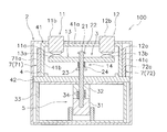
- FIG. 1 is a schematic cross-sectional view of the electromagnetic relay 100.
- the electromagnetic relay 100 includes a housing 2, a contact device 3, a contact case 4, a drive device 5, one or more magnets 6 (see FIG. 2), and one or more yokes 7. It has.
- FIG. 1 When referring to the drawings, the upper side in FIG. 1 will be described as “upper”, the lower side as “lower”, the left side as “left”, and the right side as “right” in order to make the explanation easier to understand. Further, the back side of the paper in FIG. 1 will be described as “front”, and the front side will be described as “rear”. However, these directions are defined for convenience of explanation, and do not limit the arrangement direction of the electromagnetic relay 100.
- the housing 2 has a substantially quadrangular box shape and is made of an insulating material such as resin. Inside the housing 2, a contact device 3, a contact case 4, a drive device 5, one or more magnets 6, and one or more yokes 7 are housed.
- the contact device 3 includes fixed terminals 11 and 12, a movable contact piece 13, and a movable mechanism 14.
- the fixed terminals 11 and 12 are columnar terminals and extend in the moving direction of the movable contact piece 13.
- the fixed terminals 11 and 12 extend in the vertical direction and are fixed to the upper part of the contact case 4.
- the fixed terminals 12 are arranged at intervals in the left-right direction from the fixed terminals 11.
- the fixed terminal 11 includes a fixed contact 11a and an external connection portion 11b.
- the fixed contact 11a is arranged in the contact case 4.
- the external connection portion 11b projects upward from the housing 2 and is exposed to the outside.
- the fixed terminal 12 includes a fixed contact 12a and an external connection portion 12b.
- the fixed contact 12a is arranged in the contact case 4.
- the external connection portion 12b projects upward from the housing 2 and is exposed to the outside.
- the movable contact piece 13 is a plate-shaped member that is long in one direction, and here extends in the left-right direction.
- the movable contact piece 13 is arranged in the contact case 4.
- the longitudinal direction of the movable contact piece 13 coincides with the left-right direction.
- the lateral direction of the movable contact piece 13 coincides with the front-rear direction.
- the movable contact piece 13 includes the movable contacts 13a and 13b.
- the movable contact 13a is arranged so as to face the fixed contact 11a and can come into contact with the fixed contact 11a.
- the movable contact 13b is arranged so as to face the fixed contact 12a and can come into contact with the fixed contact 12a.
- the movable contact 13b is arranged at a distance from the movable contact 13a in the left-right direction.
- the movable contact piece 13 is provided so as to be movable in the contact direction in which the movable contacts 13a and 13b come into contact with the fixed contacts 11a and 12a and in the opening and closing directions in which the movable contacts 13a and 13b are separated. That is, in the present embodiment, the movable contact piece 13 can move in the vertical direction.
- the movable mechanism 14 supports the movable contact piece 13.
- the movable mechanism 14 is movably provided at a closed position where the fixed contacts 11a and 12a and the movable contacts 13a and 13b are in contact with each other and an open position where the fixed contacts 11a and 12a and the movable contacts 13a and 13b are separated from each other.
- the movable mechanism 14 includes a drive shaft 21, a first holding member 22, a second holding member 23, and a contact spring 24.
- the drive shaft 21 is connected to the movable contact piece 13.
- the drive shaft 21 extends in the vertical direction and penetrates the movable contact piece 13 in the vertical direction.
- the drive shaft 21 is provided so as to be movable in the vertical direction.
- the first holding member 22 is fixed to the drive shaft 21 above the movable contact piece 13.
- the second holding member 23 is fixed to the drive shaft 21 below the movable contact piece 13.
- the contact spring 24 is arranged between the movable contact piece 13 and the second holding member 23. The contact spring 24 urges the movable contact piece 13 in the contact direction via the second holding member 23.
- the drive device 5 includes a movable iron core 31, a fixed iron core 32, a yoke 33, and a return spring 34. Further, the drive device 5 includes a coil and a spool (not shown). The driving device 5 moves the movable contact piece 13 in the contact direction and the opening / detaching direction via the movable mechanism 14 by electromagnetic force. Since the drive device 5 has the same configuration as the conventional one, detailed description thereof will be omitted.
- the contact case 4 is made of resin.
- the contact case 4 houses the fixed contacts 11a and 12a and the movable contact piece 13.
- the contact case 4 includes a case portion 41 and a bottom portion 42.
- the case portion 41 is arranged above the bottom portion 42.
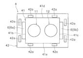
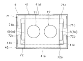
- FIG. 2 is a view of the fixed terminals 11 and 12, the magnet 6 and the contact case 4 as viewed from above.
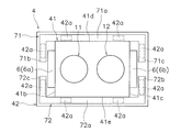
- FIG. 3 is a view of the fixed terminals 11 and 12, the magnet 6, the yoke 7, and the contact case 4 as viewed from above.
- the housing 2 is omitted.
- the case portion 41 includes an upper surface portion 41a and first to fourth side wall portions 41b to 41e.
- the upper surface portion 41a has a substantially rectangular shape in top view, and extends in the front-rear direction and the left-right direction.
- the case portion 41 is formed to have a larger dimension in the left-right direction than in the front-rear direction.
- Fixed terminals 11 and 12 penetrate the upper surface portion 41a in the vertical direction.
- the first to fourth side wall portions 41b to 41e are located on the front, rear, left and right sides of the case portion 41, and extend from the upper surface portion 41a toward the bottom portion 42.
- the first side wall portion 41b and the second side wall portion 41c are arranged so as to face each other in the left-right direction.
- the third side wall portion 41d and the fourth side wall portion 41e are arranged so as to face each other in the front-rear direction.
- the bottom portion 42 is arranged so as to cover the case portion 41 from below.
- the bottom portion 42 has a substantially rectangular shape when viewed from above, and extends in the front-rear direction and the left-right direction from the case portion 41.
- the bottom portion 42 includes a plurality of press-fit holes 42a.
- the press-fitting holes 42a are provided corresponding to the press-fitting projections 71d and 72d, which will be described later.
- the press-fit hole 42a is formed so as to be recessed from the upper surface to the lower surface of the bottom portion 42 at a position outside the case portion 41.
- two press-fitting holes 42a are provided at positions on the outer sides of the first to fourth side wall portions 41b to 41e.
- One or more magnets 6 are permanent magnets, are arranged around the contact case 4, and generate a magnetic field in the contact case 4. As a result, the Lorentz force acts on the arc generated at the contact point to extend the arc.
- One or more magnets 6 include a first magnet 6a and a second magnet 6b.
- the first magnet 6a and the second magnet 6b are arranged so as to face each other in the left-right direction.
- the first magnet 6a is arranged in contact with the outer surface of the first side wall portion 41b.
- the second magnet 6b is arranged in contact with the outer surface of the second side wall portion 41c.
- One or more yokes 7 are fixed to the contact case 4. At least a part of one or more yokes 7 is arranged in contact with the outer surface of the contact case 4. One or more yokes 7 are arranged so as to surround the periphery of the contact case 4. One or more yokes 7 include a first yoke 71 and a second yoke 72.
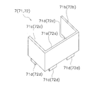
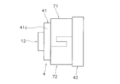
- the first yoke 71 has a substantially U-shape when viewed from above. More specifically, as shown in FIGS. 3 and 4, the first yoke 71 includes a central portion 71a, a first side portion 71b, a second side portion 71c, and a plurality of press-fitting projections 71d.
- the first side portion 71b and the second side portion 71c are examples of a pair of side portions.
- the central portion 71a extends in the front-rear direction and the up-down direction.
- the central portion 71a extends linearly in a top view.
- the central portion 71a is arranged so as to cover the outer surface of the third side wall portion 41d. In the present embodiment, the central portion 71a is arranged in contact with the outer surface of the third side wall portion 41d.
- the first side portion 71b extends in the front-rear direction from the left end of the central portion 72a so as to cover the outer surface of the first side wall portion 41b.
- the first side portion 71b extends to a position where it overlaps with the first magnet 6a in the left-right direction, and covers a part of the outer surface of the first magnet 6a.
- the second side portion 71c faces the first side portion 71b in the left-right direction.
- the second side portion 71c extends in the front-rear direction from the right end of the central portion 71a so as to cover the outer surface of the second side wall portion 41c.
- the second side portion 71c extends to a position where it overlaps the second magnet 6b in the left-right direction, and covers a part of the outer surface of the second magnet 6b.
- the press-fitting projection 71d is press-fitted and fixed in the press-fitting hole 42a.
- the first yoke 71 is fixed to the contact case 4 by press-fitting and fixing the press-fitting projection 71d into the press-fitting hole 42a.
- the press-fitting projection 71d is provided at the lower end of each of the central portion 71a, the first side portion 71b, and the second side portion 71c.
- Two press-fitting projections 71d are provided in the central portion 71a at intervals in the left-right direction.
- Each of the press-fitting projections 71d provided in the central portion 71a is provided at a position close to both ends of the central portion 71a.
- One press-fitting projection 71d is provided on each of the first side portion 71b and the second side portion 71c.
- the second yoke 72 has the same shape as the first yoke 71, and the position where it is arranged is different from that of the first yoke 71.
- the second yoke 72 is arranged apart from the first yoke 71 in the front-rear direction.
- the second yoke 72 includes a central portion 72a, a first side portion 72b, a second side portion 72c, and a plurality of press-fitting projections 72d.
- the central portion 72a is arranged so as to cover the outer surface of the fourth side wall portion 41e.
- the central portion 72a is arranged in contact with the outer surface of the fourth side wall portion 41e.
- the first side portion 72b extends in the front-rear direction from the right end of the central portion 72a so as to cover the outer surface of the second side wall portion 41c.
- the first side portion 72b extends to a position where it overlaps the second magnet 6b in the left-right direction, and covers a part of the outer surface of the second magnet 6b.
- the second side portion 72c extends in the front-rear direction from the left end of the central portion 72a so as to cover the outer surface of the first side wall portion 41b.
- the second side portion 72c extends to a position where it overlaps the first magnet 6a in the left-right direction, and covers a part of the outer surface of the first magnet 6a.
- the press-fitting projection 72d is press-fitted and fixed in the press-fitting hole 42a.
- the second yoke 72 is fixed to the contact case 4 by press-fitting and fixing the press-fitting projection 72d into the press-fitting hole 42a.
- the strength of the contact case 4 can be improved by the yoke 7 fixed to the contact case 4.
- the central portion 71a of the first yoke 71 is arranged in contact with the outer surface of the third side wall portion 41d of the case portion 41
- the central portion 72a of the second yoke 72 is the fourth side wall portion of the case portion 41. It is arranged in contact with the outer surface of 41e.
- the yoke 7 can be firmly fixed to the contact case 4. Thereby, the strength of the contact case 4 can be further increased.
- the present invention is not limited to the above embodiment, and various modifications can be made without departing from the gist of the invention.
- the shape or arrangement of the housing 2, the contact device 3, the contact case 4, the drive device 5, the magnet 6 or the yoke 7 may be changed.
- the fixed terminals 11 and 12 are columnar, but the fixed terminals 11 and 12 may be plate-shaped terminals extending in the left-right direction or the front-back direction.
- the contact case 4 is a substantially rectangular parallelepiped, but it may be a polygonal shape, a columnar shape, or a substantially elliptical column other than the rectangular parallelepiped.
- the first magnet 6a and the second magnet 6b may be arranged so as to face each other in the front-rear direction. In this case, even if the central portion 71a of the first yoke 71 is arranged in contact with the outer surface of the first side wall portion 41b and the central portion 72a of the second yoke 72 is arranged in contact with the outer surface of the second side wall portion 41c. Good. Further, the number of magnets 6 may be single or three or more.
- the yoke 7 includes two yokes, a first yoke 71 and a second yoke 72, but the yoke 7 may be single or three or more.
- the yoke 7 may be integrated and the yoke 7 may surround the entire circumference of the case portion 41.
- the yoke 7 is divided into a first yoke 71 and a second yoke 72, and the first yoke 71 and the second yoke 72 are engaged in a key shape to increase the strength of the yoke 7. You may increase it.
- the first yoke 71 is arranged in contact with the outer surface of the contact case 4, and the second yoke 72 is arranged in contact with the outer surface of the contact case 4, but the first yoke 71 and the second yoke are arranged. 72 does not necessarily have to be arranged in contact with the contact case 4.
- the first yoke 71 has a substantially U-shape, but depending on the arrangement or shape of the magnet 6, the first side portion 71b and the second side portion 71c may be omitted in the first yoke 71. May be good.
- the first side portion 72b and the second side portion 72c may be omitted.
- the means for fixing the yoke 7 to the contact case 4 is not limited to the above embodiment.
- the yoke 7 may be fixed to the contact case 4 by insert molding the yoke 7 into the contact case 4.
- a groove 4a in which at least a part of the yoke 7 fits into the contact case 4 is provided in the contact case 4, and the yoke 7 is press-fitted into the groove 4a to bring the yoke 7 into the contact case 4. It may be fixed.
- the yoke 7 may be fixed to the contact case 4 by combining the groove portion 4a and the press-fitting hole 42a.
- the central portions 71a and 72a may be press-fitted and fixed to the groove portion 4a, and the press-fitting projections 71d and 72d of the first side portions 71b and 72b may be fixed to the press-fitting holes 42a.
- the strength of the contact case can be improved.
Landscapes
- Physics & Mathematics (AREA)
- Electromagnetism (AREA)
- Arc-Extinguishing Devices That Are Switches (AREA)
- Electromagnets (AREA)
- Contacts (AREA)
Abstract
電磁継電器は、固定端子と、可動接触片と、駆動装置と、接点ケースと、1以上の磁石と、1以上のヨークと、を備える。固定端子は、固定接点を含む。可動接触片は、固定接点に対向して配置された可動接点を含む。駆動装置は、可動接点が固定接点に接触する方向及び開離する方向に可動接触片を移動させる。接点ケースは、樹脂製である。接点ケースには、固定接点及び可動接触片が収容される。1以上の磁石は、接点ケースの周囲に配置され、接点ケース内に磁界を発生させる。1以上のヨークは、接点ケースに固定される。
Description
本発明は、電磁継電器に関する。
電磁継電器は、固定接点、可動接点及び可動接触片が収容される接点ケースを備えている(特許文献1参照)。接点ケースは、接点ケース内の内圧が上昇したきに、接点ケースが膨張して変形するおそれがある。このため、特許文献1では、接点ケースをセラミック製にすることで、接点ケースの強度を確保している。
例えば、接点ケースの製造コストを抑えるために、接点ケースを樹脂製にすることが考えられる。しかしながら、樹脂製の接点ケースでは、接点ケースの強度を確保することが難しく、接点ケース内の内圧が上昇したときに、接点ケースが膨張して変形するおそれある。
本発明の課題は、樹脂製の接点ケースを備える電磁継電器において、接点ケースの強度を向上させることにある。
本発明の一態様に係る電磁継電器は、固定端子と、可動接触片と、駆動装置と、接点ケースと、1以上の磁石と、1以上のヨークと、を備える。固定端子は、固定接点を含む。可動接触片は、固定接点に対向して配置された可動接点を含む。駆動装置は、可動接点が固定接点に接触する方向及び開離する方向に可動接触片を移動させる。接点ケースは、樹脂製である。接点ケースには、固定接点及び可動接触片が収容される。1以上の磁石は、接点ケースの周囲に配置され、接点ケース内に磁界を発生させる。1以上のヨークは、接点ケースに固定される。
この電磁継電器では、接点ケースに固定されるヨークによって接点ケースの強度を向上させることができる。これにより、接点ケース内の内圧が上昇したときに、接点ケースの膨張による変形を抑制することができる。
ヨークの少なくとも一部は、接点ケースの外面に接触して配置されてもよい。この場合は、接点ケースの膨張による変形をヨークによって効果的に抑制することができる。
ヨークは、接点ケースに圧入固定されてもよい。この場合は、ヨークを接点ケースに強固に固定することができる。
ヨークは、可動接触片の移動方向に突出する1以上の圧入突起を含んでもよい。接点ケースは、圧入突起に対応して設けられ、圧入突起が圧入される1以上の圧入穴を含んでもよい。この場合は、簡単な構成でヨークを接点ケースに固定することができる。
ヨークは、接点ケースの周囲を囲むように配置されてもよい。この場合は、接点ケースの膨張による変形を接点ケースの広範囲にわたって抑制することができる。
ヨークは、可動接触片の長手方向又は短手方向のいずれか一方に延びる中央部と、中央部の両端から可動接触片の長手方向及び短手方向のいずれか他方に延びる1対の側部と、を含んでもよい。圧入突起は、中央部と1対の側部のうち、少なくとも1対の側部のそれぞれに設けられてもよい。この場合は、1対の側部を含むヨークにおいてヨークを接点ケースに強固に固定することができる。
ヨークは、接点ケースにインサート成形されてもよい。この場合においても、ヨークによって接点ケースの強度を向上させることができるので、接点ケースの膨張による変形を抑制することができる。
固定端子は、円柱状であり、可動接触片の移動方向に延びていてもよい。この場合は、円柱状の固定端子を含む電磁継電器において、接点ケースの膨張による変形を抑制することができる。
本発明によれば、樹脂製の接点ケースを備える電磁継電器において、接点ケースの強度を向上させることができる。
以下、本発明の一態様に係る電磁継電器の実施形態について、図面を参照して説明する。図1は電磁継電器100の断面模式図である。図1に示すように、電磁継電器100は、ハウジング2と、接点装置3と、接点ケース4と、駆動装置5と、1以上の磁石6(図2参照)と、1以上のヨーク7と、を備えている。
なお、図面を参照するときにおいて、説明を分かり易くするために図1における上側を「上」、下側を「下」、左側を「左」、右側を「右」として説明する。また、図1における紙面の奥側を「前」、手前側を「後」として説明する。ただし、これらの方向は、説明の便宜上、定義されるものであって、電磁継電器100の配置方向を限定するものではない。
ハウジング2は、略四角形の箱型であり、樹脂などの絶縁性を有する材料で形成されている。ハウジング2の内部には、接点装置3、接点ケース4と、駆動装置5と、1以上の磁石6及び1以上のヨーク7が収容されている。
接点装置3は、図1に示すように、固定端子11,12と、可動接触片13と、可動機構14と、を含む。固定端子11,12は、円柱状の端子であり、可動接触片13の移動方向に延びている。ここでは、固定端子11,12は、上下方向に延びており、接点ケース4の上部に固定されている。固定端子12は、固定端子11と左右方向に間隔を隔てて配置されている。
固定端子11は、固定接点11aと、外部接続部11bと、を含む。固定接点11aは、接点ケース4内に配置されている。外部接続部11bは、ハウジング2から上方に突出して外部に露出している。
固定端子12は、固定接点12aと、外部接続部12bと、を含む。固定接点12aは、接点ケース4内に配置されている。外部接続部12bは、ハウジング2から上方に突出して外部に露出している。
可動接触片13は、一方向に長い板状部材であり、ここでは左右方向に延びている。可動接触片13は、接点ケース4内に配置されている。本実施形態において、可動接触片13の長手方向は、左右方向と一致する。また、可動接触片13の短手方向は、前後方向と一致する。
可動接触片13は、可動接点13a,13bを含む。可動接点13aは、固定接点11aに対向して配置され、固定接点11aに接触可能である。可動接点13bは、固定接点12aに対向して配置され、固定接点12aに接触可能である。可動接点13bは、可動接点13aと左右方向に間隔を隔てて配置されている。
可動接触片13は、可動接点13a,13bが固定接点11a,12aに接触する接触方向及び開離する開離方向に移動可能に設けられる。すなわち、本実施形態では、可動接触片13は、上下方向に移動可能である。
可動機構14は、可動接触片13を支持する。可動機構14は、固定接点11a,12aと可動接点13a,13bとが接触する閉位置と、固定接点11a,12aと可動接点13a,13bとが開離する開位置とに移動可能に設けられる。
可動機構14は、駆動軸21と、第1保持部材22と、第2保持部材23と、接点バネ24と、を含む。駆動軸21は、可動接触片13に連結される。駆動軸21は、上下方向に延びており、可動接触片13を上下方向に貫通している。駆動軸21は、上下方向に移動可能に設けられる。
第1保持部材22は、可動接触片13よりも上方で駆動軸21に固定されている。第2保持部材23は、可動接触片13よりも下方で駆動軸21に固定されている。接点バネ24は、可動接触片13と第2保持部材23の間に配置されている。接点バネ24は、第2保持部材23を介して可動接触片13を接触方向に付勢する。
駆動装置5は、可動鉄心31と、固定鉄心32と、ヨーク33と、復帰バネ34と、を含む。また、駆動装置5は、図示しないコイル及びスプールを含む。駆動装置5は、電磁力によって、可動機構14を介して可動接触片13を接触方向と開離方向とに移動させる。
なお、駆動装置5は、従来と同様の構成であるため詳細な説明を省略する。
なお、駆動装置5は、従来と同様の構成であるため詳細な説明を省略する。
接点ケース4は、樹脂製である。接点ケース4には、固定接点11a,12a及び可動接触片13が収容されている。接点ケース4は、ケース部41と、底部42とを含む。ケース部41は、底部42の上部に配置されている。
図2は、固定端子11,12、磁石6及び接点ケース4を上方から見た図である。図3は、固定端子11,12、磁石6、ヨーク7及び接点ケース4を上方から見た図である。図2及び図3では、ハウジング2を省略して示している。ケース部41は、上面部41aと、第1~第4側壁部41b~41eと、を含む。上面部41aは、上面視において略矩形状であり、前後方向及び左右方向に延びている。ここでは、ケース部41は、前後方向よりも左右方向の寸法が大きく形成されている。上面部41aは、固定端子11,12が上下方向に貫通している。第1~第4側壁部41b~41eは、ケース部41の前後左右にそれぞれ位置しており、上面部41aから底部42に向かって延びている。第1側壁部41bと第2側壁部41cは、左右方向に対向して配置されている。第3側壁部41dと第4側壁部41eは、前後方向に対向して配置されている。
底部42は、ケース部41を下方から覆うように配置されている。底部42は、上面視において略矩形状であり、ケース部41よりも前後方向及び左右方向に延びている。底部42は、複数の圧入穴42aを含む。圧入穴42aは、後述する圧入突起71d,72dに対応して設けられている。圧入穴42aは、ケース部41よりも外側の位置で底部42の上面から下面に向かって凹んで形成されている。本実施形態では、圧入穴42aが第1~第4側壁部41b~41eのそれぞれの外側の位置に2個ずつ設けられている。
1以上の磁石6は、永久磁石であり、接点ケース4の周囲に配置され、接点ケース4内に磁界を発生させる。これにより、接点に生じるアークにローレンツ力が作用してアークが伸長される。
1以上の磁石6は、第1磁石6aと、第2磁石6bとを含む。第1磁石6aと第2磁石6bは、左右方向に対向して配置されている。第1磁石6aは、第1側壁部41bの外面に接触して配置されている。第2磁石6bは、第2側壁部41cの外面に接触して配置されている。
1以上のヨーク7は、接点ケース4に固定されている。1以上のヨーク7の少なくとも一部は、接点ケース4の外面に接触し配置されている。1以上のヨーク7は、接点ケース4の周囲を囲むように配置されている。1以上のヨーク7は、第1ヨーク71と、第2ヨーク72とを含む。
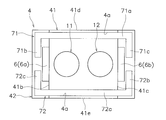
第1ヨーク71は、上面視において略U字形状である。詳細には、図3及び図4に示すように、第1ヨーク71は、中央部71aと、第1側部71bと、第2側部71cと、複数の圧入突起71dと、を含む。第1側部71bと第2側部71cは、1対の側部の一例である。
中央部71aは、前後方向及び上下方向に延びている。中央部71aは、上面視において直線状に延びている。中央部71aは、第3側壁部41dの外面を覆うように配置されている。本実施形態では、中央部71aは、第3側壁部41dの外面に接触して配置されている。
第1側部71bは、第1側壁部41bの外面を覆うように中央部72aの左端から前後方向に延びている。第1側部71bは、第1磁石6aと左右方向に重なる位置まで延びており、第1磁石6aの外面の一部を覆う。
第2側部71cは、第1側部71bと左右方向に対向している。第2側部71cは、第2側壁部41cの外面を覆うように中央部71aの右端から前後方向に延びている。第2側部71cは、第2磁石6bと左右方向に重なる位置まで延びており、第2磁石6bの外面の一部を覆う。
圧入突起71dは、圧入穴42aに圧入固定される。圧入突起71dが圧入穴42aに圧入固定されることで、第1ヨーク71が接点ケース4に固定される。圧入突起71dは、図4に示すように、中央部71a、第1側部71b及び第2側部71cのそれぞれの下端に設けられている。中央部71aには、左右方向に間隔を隔てて2つの圧入突起71dが設けられている。中央部71aに設けられる圧入突起71dのそれぞれは、中央部71aの両端に近接した位置に設けられている。第1側部71b及び第2側部71cには、それぞれ1つの圧入突起71dが設けられている。
第2ヨーク72は、第1ヨーク71と同じ形状であり、配置される位置が第1ヨーク71と異なる。第2ヨーク72は、第1ヨーク71と前後方向に離れて配置されている。第2ヨーク72は、中央部72aと、第1側部72bと、第2側部72cと、複数の圧入突起72dと、を含む。
中央部72aは、第4側壁部41eの外面を覆うように配置されている。本実施形態では、中央部72aは、第4側壁部41eの外面に接触して配置されている。第1側部72bは、第2側壁部41cの外面を覆うように中央部72aの右端から前後方向に延びている。第1側部72bは、第2磁石6bと左右方向に重なる位置まで延びており、第2磁石6bの外面の一部を覆う。第2側部72cは、第1側壁部41bの外面を覆うように中央部72aの左端から前後方向に延びている。第2側部72cは、第1磁石6aと左右方向に重なる位置まで延びており、第1磁石6aの外面の一部を覆う。
圧入突起72dは圧入穴42aに圧入固定される。圧入突起72dが圧入穴42aに圧入固定されることで、第2ヨーク72が接点ケース4に固定される。
上記構成の電磁継電器100では、接点ケース4に固定されるヨーク7によって接点ケース4の強度を向上させることができる。これにより、接点ケース4内の内圧が上昇したときに、接点ケース4の膨張による変形を抑制することができる。特に本実施形態では、第1ヨーク71の中央部71aがケース部41の第3側壁部41dの外面に接触して配置され、第2ヨーク72の中央部72aがケース部41の第4側壁部41eの外面に接触して配置されている。これにより、接点ケース4内の内圧が上昇したときに、接点ケース4の膨張による変形を効果的に抑制することができる。また、複数の圧入突起71d,72dが複数の圧入穴42aに圧入されて接点ケース4にヨーク7固定されるので、接点ケース4にヨーク7を強固に固定することができる。これにより、接点ケース4の強度をさらに高めることができる。
以上、本発明の一態様に係る電磁継電器の実施形態について説明したが、本発明は上記実施形態に限定されるものではなく、発明の要旨を逸脱しない範囲で種々の変更が可能である。例えば、ハウジング2、接点装置3、接点ケース4、駆動装置5、磁石6或いはヨーク7の形状、或いは配置が変更されてもよい。
前記実施形態では固定端子11,12が円柱状であったが、固定端子11,12は、左右方向或いは前後方向に延びる板状の端子であってもよい。
前記実施形態では接点ケース4が略直方体であったが、直方体以外の多角形状、円柱状、或いは略楕円柱であってもよい。
図5に示すように、第1磁石6aと第2磁石6bとが前後方向に対向して配置されてもよい。この場合、第1ヨーク71の中央部71aが第1側壁部41bの外面に接触して配置され、第2ヨーク72の中央部72aが第2側壁部41cの外面に接触して配置されてもよい。また、磁石6は、単一或いは3つ以上であってもよい。
前記実施形態では、ヨーク7が第1ヨーク71と第2ヨーク72の2個のヨークを含んでいたが、ヨーク7は、単一或いは3つ以上であってもよい。例えば、図6に示すように、ヨーク7を一体にして、ヨーク7でケース部41の周囲全体を囲んでもよい。この場合、図7に示すように、ヨーク7を第1ヨーク71と第2ヨーク72とに分割して第1ヨーク71と第2ヨーク72とを鍵状に係合させてヨーク7の強度を高めてもよい。
前記実施形態では、第1ヨーク71が接点ケース4の外面に接触して配置され、第2ヨーク72が接点ケース4の外面に接触して配置されていたが、第1ヨーク71及び第2ヨーク72は、必ずしも接点ケース4に接触して配置されなくてもよい。また、前記実施形態では、第1ヨーク71が略U字形状であったが、磁石6の配置或いは形状によっては、第1ヨーク71において第1側部71b及び第2側部71cが省略されてもよい。同様に、第2ヨーク72においても、第1側部72b及び第2側部72cが省略されてもよい。
接点ケース4にヨーク7を固定する手段は前記実施形態に限定されるものではない。例えば、図8に示すように、ヨーク7が接点ケース4にインサート成形されることで、ヨーク7が接点ケース4に固定されてもよい。或いは、図9に示すように、接点ケース4にヨーク7の少なくとも一部が嵌合する溝部4aを接点ケース4に設けて、溝部4aにヨーク7を圧入することでヨーク7が接点ケース4に固定されてもよい。また、溝部4aと圧入穴42aとを組み合わせて、ヨーク7が接点ケース4に固定されてもよい。例えば、中央部71a,72aが溝部4aに圧入固定され、第1側部71b,72bの圧入突起71d,72dが圧入穴42aに固定されてもよい。
本発明によれば、樹脂製の接点ケースを備える電磁継電器において、接点ケースの強度を向上させることができる。
4 接点ケース
5 駆動装置
6 磁石
7 ヨーク
11,12 固定端子
11a,11b 固定接点
13 可動接触片
13a,13b 可動接点
42a 圧入穴
71a,72a 中央部
71b,71c 1対の側部
71d,72d 圧入突起
72b,72c 1対の側部
100 電磁継電器
5 駆動装置
6 磁石
7 ヨーク
11,12 固定端子
11a,11b 固定接点
13 可動接触片
13a,13b 可動接点
42a 圧入穴
71a,72a 中央部
71b,71c 1対の側部
71d,72d 圧入突起
72b,72c 1対の側部
100 電磁継電器
Claims (8)
- 固定接点を含む固定端子と、
前記固定接点に対向して配置された可動接点を含む可動接触片と、
前記可動接点が前記固定接点に接触する方向及び開離する方向に前記可動接触片を移動させる駆動装置と、
前記固定接点及び前記可動接触片が収容される樹脂製の接点ケースと、
前記接点ケースの周囲に配置され、前記接点ケース内に磁界を発生させる1以上の磁石と、
前記接点ケースに固定される1以上のヨークと、
を備える、電磁継電器。 - 前記ヨークの少なくとも一部は、前記接点ケースの外面に接触して配置されている、
請求項1に記載の電磁継電器。 - 前記ヨークは、前記接点ケースに圧入固定されている、
請求項1又は2に記載の電磁継電器。 - 前記ヨークは、前記可動接触片の移動方向に突出する1以上の圧入突起を含み、
前記接点ケースは、前記圧入突起に対応して設けられ、前記圧入突起が圧入される1以上の圧入穴を含む、
請求項1から3のいずれか1項に記載の電磁継電器。 - 前記ヨークは、前記接点ケースの周囲を囲むように配置されている、
請求項4に記載の電磁継電器。 - 前記ヨークは、前記可動接触片の長手方向又は短手方向のいずれか一方に延びる中央部と、前記中央部の両端から前記可動接触片の長手方向及び短手方向のいずれか他方に延びる1対の側部と、を含み、
前記圧入突起は、前記中央部と1対の前記側部のうち、少なくとも1対の前記側部のそれぞれに設けられている、
請求項5に記載の電磁継電器。 - 前記ヨークは、前記接点ケースにインサート成形されている、
請求項1に記載の電磁継電器。 - 前記固定端子は、円柱状であり、前記可動接触片の移動方向に延びている、
請求項1から7のいずれか1項に記載の電磁継電器。
Priority Applications (3)
| Application Number | Priority Date | Filing Date | Title |
|---|---|---|---|
| DE112020006217.1T DE112020006217T5 (de) | 2019-12-19 | 2020-11-16 | Elektromagnetisches Relais |
| US17/782,156 US12183528B2 (en) | 2019-12-19 | 2020-11-16 | Electromagnetic relay |
| CN202080084919.7A CN114762072A (zh) | 2019-12-19 | 2020-11-16 | 电磁继电器 |
Applications Claiming Priority (2)
| Application Number | Priority Date | Filing Date | Title |
|---|---|---|---|
| JP2019-229088 | 2019-12-19 | ||
| JP2019229088A JP7380175B2 (ja) | 2019-12-19 | 2019-12-19 | 電磁継電器 |
Publications (1)
| Publication Number | Publication Date |
|---|---|
| WO2021124754A1 true WO2021124754A1 (ja) | 2021-06-24 |
Family
ID=76431535
Family Applications (1)
| Application Number | Title | Priority Date | Filing Date |
|---|---|---|---|
| PCT/JP2020/042578 Ceased WO2021124754A1 (ja) | 2019-12-19 | 2020-11-16 | 電磁継電器 |
Country Status (5)
| Country | Link |
|---|---|
| US (1) | US12183528B2 (ja) |
| JP (1) | JP7380175B2 (ja) |
| CN (1) | CN114762072A (ja) |
| DE (1) | DE112020006217T5 (ja) |
| WO (1) | WO2021124754A1 (ja) |
Families Citing this family (3)
| Publication number | Priority date | Publication date | Assignee | Title |
|---|---|---|---|---|
| JP7735849B2 (ja) * | 2021-12-15 | 2025-09-09 | オムロン株式会社 | 電磁継電器 |
| JP7903270B2 (ja) | 2022-07-22 | 2026-08-12 | オムロン株式会社 | 電磁継電器 |
| EP4758646A1 (de) * | 2023-08-10 | 2026-06-17 | Pierburg GmbH | Hochvoltschütz oder hochvoltrelais |
Citations (3)
| Publication number | Priority date | Publication date | Assignee | Title |
|---|---|---|---|---|
| JP2003197053A (ja) * | 2001-12-25 | 2003-07-11 | Mitsubishi Electric Corp | 消弧装置及びそれを用いた車載用開閉器 |
| JP2012199120A (ja) * | 2011-03-22 | 2012-10-18 | Panasonic Corp | 接点装置 |
| JP2015170531A (ja) * | 2014-03-07 | 2015-09-28 | パナソニックIpマネジメント株式会社 | 電磁継電器 |
Family Cites Families (23)
| Publication number | Priority date | Publication date | Assignee | Title |
|---|---|---|---|---|
| JP2625975B2 (ja) * | 1988-10-21 | 1997-07-02 | 株式会社デンソー | 電磁継電器 |
| CN1224069C (zh) * | 2002-08-21 | 2005-10-19 | 厦门宏发电声有限公司 | 左右变截面腔体小型化变截面大功率电磁继电器 |
| JP2005026182A (ja) | 2003-07-02 | 2005-01-27 | Matsushita Electric Works Ltd | 電磁開閉装置 |
| JP2007305468A (ja) * | 2006-05-12 | 2007-11-22 | Omron Corp | 電磁継電器 |
| JP2007305467A (ja) * | 2006-05-12 | 2007-11-22 | Omron Corp | 電磁継電器、その調整方法および調整システム |
| JP4765761B2 (ja) * | 2006-05-12 | 2011-09-07 | オムロン株式会社 | 電磁継電器 |
| JP5163318B2 (ja) | 2008-06-30 | 2013-03-13 | オムロン株式会社 | 電磁石装置 |
| JP5307779B2 (ja) | 2010-08-31 | 2013-10-02 | 富士電機機器制御株式会社 | 電磁開閉器 |
| JP5684649B2 (ja) * | 2011-05-19 | 2015-03-18 | 富士電機機器制御株式会社 | 電磁接触器 |
| JP6300157B2 (ja) * | 2013-08-02 | 2018-03-28 | パナソニックIpマネジメント株式会社 | 電磁継電器 |
| JP6265657B2 (ja) * | 2013-08-26 | 2018-01-24 | 富士通コンポーネント株式会社 | 電磁継電器 |
| JP6202943B2 (ja) * | 2013-08-26 | 2017-09-27 | 富士通コンポーネント株式会社 | 電磁継電器 |
| JP2015056230A (ja) * | 2013-09-10 | 2015-03-23 | パナソニック株式会社 | 封止接点装置 |
| JP2017050274A (ja) * | 2015-09-04 | 2017-03-09 | オムロン株式会社 | 接点開閉装置 |
| JP2017195160A (ja) * | 2016-04-22 | 2017-10-26 | オムロン株式会社 | 電磁継電器 |
| CN109074993B (zh) * | 2016-04-22 | 2019-12-03 | 欧姆龙株式会社 | 触头开闭装置以及使用其的电磁继电器 |
| EP3471127A1 (en) * | 2016-06-14 | 2019-04-17 | Fuji Electric Fa Components & Systems Co., Ltd. | Contact device and electromagnetic contactor using same |
| JP6668997B2 (ja) * | 2016-07-29 | 2020-03-18 | オムロン株式会社 | 電磁継電器 |
| JP6828294B2 (ja) * | 2016-07-29 | 2021-02-10 | オムロン株式会社 | 電磁継電器 |
| JP2019032944A (ja) * | 2017-08-04 | 2019-02-28 | オムロン株式会社 | 電磁継電器およびスマートメータ |
| JP6848924B2 (ja) | 2018-03-30 | 2021-03-24 | オムロン株式会社 | リレー |
| JP6835029B2 (ja) * | 2018-03-30 | 2021-02-24 | オムロン株式会社 | リレー |
| PL4086931T3 (pl) * | 2019-12-31 | 2026-07-20 | Xiamen Hongfa Electric Power Controls Co., Ltd. | Przekaźnik dc do przeciwdziałania prądowi zwarciowemu oraz gaszenia łuku |
-
2019
- 2019-12-19 JP JP2019229088A patent/JP7380175B2/ja active Active
-
2020
- 2020-11-16 US US17/782,156 patent/US12183528B2/en active Active
- 2020-11-16 WO PCT/JP2020/042578 patent/WO2021124754A1/ja not_active Ceased
- 2020-11-16 DE DE112020006217.1T patent/DE112020006217T5/de active Pending
- 2020-11-16 CN CN202080084919.7A patent/CN114762072A/zh active Pending
Patent Citations (3)
| Publication number | Priority date | Publication date | Assignee | Title |
|---|---|---|---|---|
| JP2003197053A (ja) * | 2001-12-25 | 2003-07-11 | Mitsubishi Electric Corp | 消弧装置及びそれを用いた車載用開閉器 |
| JP2012199120A (ja) * | 2011-03-22 | 2012-10-18 | Panasonic Corp | 接点装置 |
| JP2015170531A (ja) * | 2014-03-07 | 2015-09-28 | パナソニックIpマネジメント株式会社 | 電磁継電器 |
Also Published As
| Publication number | Publication date |
|---|---|
| CN114762072A (zh) | 2022-07-15 |
| US12183528B2 (en) | 2024-12-31 |
| US20230005691A1 (en) | 2023-01-05 |
| JP2021097002A (ja) | 2021-06-24 |
| DE112020006217T5 (de) | 2022-11-03 |
| JP7380175B2 (ja) | 2023-11-15 |
Similar Documents
| Publication | Publication Date | Title |
|---|---|---|
| CN103155082B (zh) | 电磁开关 | |
| CN102024625B (zh) | 电磁继电器 | |
| JP5559662B2 (ja) | 接点装置 | |
| US20210082649A1 (en) | Electromagnetic relay | |
| JP6300153B2 (ja) | 電磁継電器 | |
| JP7423944B2 (ja) | 電磁継電器 | |
| JP5821008B2 (ja) | 接点装置 | |
| CN103339705A (zh) | 电磁继电器 | |
| JP7501409B2 (ja) | 電磁継電器 | |
| JP7380175B2 (ja) | 電磁継電器 | |
| JP2015216054A (ja) | 接点装置 | |
| JP2012104364A (ja) | 接点装置 | |
| KR102324516B1 (ko) | 직류 릴레이 | |
| JP2022141412A (ja) | 電磁継電器 | |
| JP5821009B2 (ja) | 接点装置 | |
| JP2006310247A (ja) | 電磁開閉装置 | |
| JP4645659B2 (ja) | 電磁継電器 | |
| JP7845010B2 (ja) | 電磁継電器 | |
| JP2012104366A (ja) | 接点装置 | |
| JP2012104359A (ja) | 接点装置 | |
| JP2012104363A (ja) | 接点装置 | |
| JP4458064B2 (ja) | 電磁開閉装置 | |
| JP2012104361A (ja) | 接点装置 | |
| JP2012104365A (ja) | 接点装置 | |
| JP7417351B2 (ja) | 電磁継電器 |
Legal Events
| Date | Code | Title | Description |
|---|---|---|---|
| 121 | Ep: the epo has been informed by wipo that ep was designated in this application |
Ref document number: 20901429 Country of ref document: EP Kind code of ref document: A1 |
|
| 122 | Ep: pct application non-entry in european phase |
Ref document number: 20901429 Country of ref document: EP Kind code of ref document: A1 |