WO2021124557A1 - 圧縮機システム、圧縮機および冷凍サイクル装置 - Google Patents
圧縮機システム、圧縮機および冷凍サイクル装置 Download PDFInfo
- Publication number
- WO2021124557A1 WO2021124557A1 PCT/JP2019/050134 JP2019050134W WO2021124557A1 WO 2021124557 A1 WO2021124557 A1 WO 2021124557A1 JP 2019050134 W JP2019050134 W JP 2019050134W WO 2021124557 A1 WO2021124557 A1 WO 2021124557A1
- Authority
- WO
- WIPO (PCT)
- Prior art keywords
- bearing
- voids
- compressor
- peripheral surface
- wear
- Prior art date
- Legal status (The legal status is an assumption and is not a legal conclusion. Google has not performed a legal analysis and makes no representation as to the accuracy of the status listed.)
- Ceased
Links
Images








Classifications
-
- G—PHYSICS
- G01—MEASURING; TESTING
- G01M—TESTING STATIC OR DYNAMIC BALANCE OF MACHINES OR STRUCTURES; TESTING OF STRUCTURES OR APPARATUS, NOT OTHERWISE PROVIDED FOR
- G01M13/00—Testing of machine parts
- G01M13/04—Bearings
- G01M13/045—Acoustic or vibration analysis
-
- F—MECHANICAL ENGINEERING; LIGHTING; HEATING; WEAPONS; BLASTING
- F04—POSITIVE - DISPLACEMENT MACHINES FOR LIQUIDS; PUMPS FOR LIQUIDS OR ELASTIC FLUIDS
- F04B—POSITIVE-DISPLACEMENT MACHINES FOR LIQUIDS; PUMPS
- F04B49/00—Control, e.g. of pump delivery, or pump pressure of, or safety measures for, machines, pumps, or pumping installations, not otherwise provided for, or of interest apart from, groups F04B1/00 - F04B47/00
- F04B49/10—Other safety measures
-
- F—MECHANICAL ENGINEERING; LIGHTING; HEATING; WEAPONS; BLASTING
- F04—POSITIVE - DISPLACEMENT MACHINES FOR LIQUIDS; PUMPS FOR LIQUIDS OR ELASTIC FLUIDS
- F04B—POSITIVE-DISPLACEMENT MACHINES FOR LIQUIDS; PUMPS
- F04B51/00—Testing machines, pumps, or pumping installations
-
- F—MECHANICAL ENGINEERING; LIGHTING; HEATING; WEAPONS; BLASTING
- F04—POSITIVE - DISPLACEMENT MACHINES FOR LIQUIDS; PUMPS FOR LIQUIDS OR ELASTIC FLUIDS
- F04C—ROTARY-PISTON, OR OSCILLATING-PISTON, POSITIVE-DISPLACEMENT MACHINES FOR LIQUIDS; ROTARY-PISTON, OR OSCILLATING-PISTON, POSITIVE-DISPLACEMENT PUMPS
- F04C18/00—Rotary-piston pumps specially adapted for elastic fluids
- F04C18/02—Rotary-piston pumps specially adapted for elastic fluids of arcuate-engagement type, i.e. with circular translatory movement of co-operating members, each member having the same number of teeth or tooth-equivalents
- F04C18/0207—Rotary-piston pumps specially adapted for elastic fluids of arcuate-engagement type, i.e. with circular translatory movement of co-operating members, each member having the same number of teeth or tooth-equivalents both members having co-operating elements in spiral form
- F04C18/0215—Rotary-piston pumps specially adapted for elastic fluids of arcuate-engagement type, i.e. with circular translatory movement of co-operating members, each member having the same number of teeth or tooth-equivalents both members having co-operating elements in spiral form where only one member is moving
-
- F—MECHANICAL ENGINEERING; LIGHTING; HEATING; WEAPONS; BLASTING
- F04—POSITIVE - DISPLACEMENT MACHINES FOR LIQUIDS; PUMPS FOR LIQUIDS OR ELASTIC FLUIDS
- F04C—ROTARY-PISTON, OR OSCILLATING-PISTON, POSITIVE-DISPLACEMENT MACHINES FOR LIQUIDS; ROTARY-PISTON, OR OSCILLATING-PISTON, POSITIVE-DISPLACEMENT PUMPS
- F04C29/00—Component parts, details or accessories of pumps or pumping installations, not provided for in groups F04C18/00 - F04C28/00
-
- G—PHYSICS
- G01—MEASURING; TESTING
- G01B—MEASURING LENGTH, THICKNESS OR SIMILAR LINEAR DIMENSIONS; MEASURING ANGLES; MEASURING AREAS; MEASURING IRREGULARITIES OF SURFACES OR CONTOURS
- G01B7/00—Measuring arrangements characterised by the use of electric or magnetic techniques
-
- F—MECHANICAL ENGINEERING; LIGHTING; HEATING; WEAPONS; BLASTING
- F04—POSITIVE - DISPLACEMENT MACHINES FOR LIQUIDS; PUMPS FOR LIQUIDS OR ELASTIC FLUIDS
- F04C—ROTARY-PISTON, OR OSCILLATING-PISTON, POSITIVE-DISPLACEMENT MACHINES FOR LIQUIDS; ROTARY-PISTON, OR OSCILLATING-PISTON, POSITIVE-DISPLACEMENT PUMPS
- F04C2240/00—Components
- F04C2240/50—Bearings
- F04C2240/54—Hydrostatic or hydrodynamic bearing assemblies specially adapted for rotary positive displacement pumps or compressors
-
- F—MECHANICAL ENGINEERING; LIGHTING; HEATING; WEAPONS; BLASTING
- F04—POSITIVE - DISPLACEMENT MACHINES FOR LIQUIDS; PUMPS FOR LIQUIDS OR ELASTIC FLUIDS
- F04C—ROTARY-PISTON, OR OSCILLATING-PISTON, POSITIVE-DISPLACEMENT MACHINES FOR LIQUIDS; ROTARY-PISTON, OR OSCILLATING-PISTON, POSITIVE-DISPLACEMENT PUMPS
- F04C2270/00—Control; Monitoring or safety arrangements
- F04C2270/12—Vibration
-
- F—MECHANICAL ENGINEERING; LIGHTING; HEATING; WEAPONS; BLASTING
- F04—POSITIVE - DISPLACEMENT MACHINES FOR LIQUIDS; PUMPS FOR LIQUIDS OR ELASTIC FLUIDS
- F04C—ROTARY-PISTON, OR OSCILLATING-PISTON, POSITIVE-DISPLACEMENT MACHINES FOR LIQUIDS; ROTARY-PISTON, OR OSCILLATING-PISTON, POSITIVE-DISPLACEMENT PUMPS
- F04C2270/00—Control; Monitoring or safety arrangements
- F04C2270/16—Wear
-
- F—MECHANICAL ENGINEERING; LIGHTING; HEATING; WEAPONS; BLASTING
- F04—POSITIVE - DISPLACEMENT MACHINES FOR LIQUIDS; PUMPS FOR LIQUIDS OR ELASTIC FLUIDS
- F04C—ROTARY-PISTON, OR OSCILLATING-PISTON, POSITIVE-DISPLACEMENT MACHINES FOR LIQUIDS; ROTARY-PISTON, OR OSCILLATING-PISTON, POSITIVE-DISPLACEMENT PUMPS
- F04C2270/00—Control; Monitoring or safety arrangements
- F04C2270/80—Diagnostics
-
- F—MECHANICAL ENGINEERING; LIGHTING; HEATING; WEAPONS; BLASTING
- F04—POSITIVE - DISPLACEMENT MACHINES FOR LIQUIDS; PUMPS FOR LIQUIDS OR ELASTIC FLUIDS
- F04C—ROTARY-PISTON, OR OSCILLATING-PISTON, POSITIVE-DISPLACEMENT MACHINES FOR LIQUIDS; ROTARY-PISTON, OR OSCILLATING-PISTON, POSITIVE-DISPLACEMENT PUMPS
- F04C23/00—Combinations of two or more pumps, each being of rotary-piston or oscillating-piston type, specially adapted for elastic fluids; Pumping installations specially adapted for elastic fluids; Multi-stage pumps specially adapted for elastic fluids
- F04C23/008—Hermetic pumps
Definitions
- the present invention relates to a compressor system, a compressor and a refrigeration cycle device including a compressor having bearings that support a rotating shaft.
- Patent Document 1 As a device for detecting bearing wear in a closed compressor.
- a plurality of metal pieces are provided so as to maintain a slight gap with respect to the rotating shaft and surround the rotating shaft.
- the plurality of metal pieces are molded with an insulating material such as resin to form a tubular shape, and are arranged so as to surround the rotating shaft by being arranged on the outer periphery of the rotating shaft.
- the molded portion between the metal piece and the rotating shaft functions as a bearing, and when the bearing wears, the rotating shaft comes into contact with the metal piece and the current flowing through the rotating shaft changes.
- wear of the bearing is detected based on the change in the current.
- Patent Document 1 in order to detect wear of bearings, a tubular member obtained by molding a plurality of metal pieces is required in the compressor, and there is a problem that the structure of the compressor becomes complicated.
- the present invention is for solving the above-mentioned problems, and an object of the present invention is to provide a compressor system, a compressor and a refrigeration cycle device equipped with a compressor having a simple structure and easily detecting wear of bearings. And.
- the compressor system according to the present invention is based on a compressor having bearings that support the rotating shaft, a sensor that measures an index value that correlates with the movement of the rotating shaft during operation of the compressor, and a measured value of the sensor. It is equipped with a wear detection unit that detects the degree of wear of the bearing, and the bearing is composed of a sliding bearing. In the bearing, a plurality of voids are formed at intervals in the circumferential direction, and the inner peripheral surface of the bearing is formed due to the wear of the bearing.
- the bearing is configured so that the positional relationship between the bearing and the plurality of voids changes to change the shape of the inner peripheral surface of the bearing, and the wear detector is based on the change in the measured value due to the change in the shape of the inner peripheral surface of the bearing. It detects the degree of wear of the bearing.
- the positional relationship between the inner peripheral surface of the bearing and the plurality of voids changes and the shape of the inner peripheral surface of the bearing changes, so that the wear condition of the bearing can be detected and the bearing can be detected.
- the change in the shape of the inner peripheral surface of the bearing can be realized by providing a plurality of voids in the bearing. Therefore, it is possible to detect the wear condition of the bearing with a simple structure in which a plurality of voids are provided in the bearing.
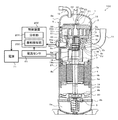
- FIG. It is schematic cross-sectional view which shows the compressor system which concerns on Embodiment 1.
- FIG. It is the schematic sectional drawing of the bearing of the compressor which concerns on Embodiment 1.
- FIG. It is an enlarged schematic cross-sectional view of the peripheral part including the void of FIG.
- FIG. It is a figure which shows the occurrence frequency of the abnormal peak in the frequency analysis result by the analysis part of the compressor system which concerns on Embodiment 1.
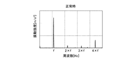
- FIG. It is a figure which shows an example of the frequency analysis result in a normal state in the analysis part of the compressor system which concerns on Embodiment 1.
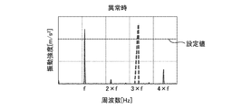
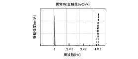
- FIG. It is a figure which shows an example of the frequency analysis result at the time of abnormality in the analysis part of the compressor system which concerns on Embodiment 1.
- FIG. It is the schematic sectional drawing of the bearing of the compressor which concerns on Embodiment 2.
- FIG. It is an enlarged cross-sectional view of the peripheral part including the 2nd void of FIG. It is a figure which shows an example of the frequency analysis result at the time of ⁇ 1 wear in the analysis part of the compressor system which concerns on Embodiment 2.
- FIG. It is a figure which shows the relationship between the bearing of the abnormality occurrence in the case of the pattern 1 in the compressor system which concerns on Embodiment 3 and the occurrence frequency of an abnormality peak based on frequency analysis.
- FIG. 3 is an enlarged schematic cross-sectional view of a peripheral portion including a gap in FIG. It is a figure which shows an example of the frequency analysis result in the normal state in the compressor system which concerns on Embodiment 4.
- FIG. It is a figure which shows an example of the frequency analysis result at the time of abnormality in the compressor system which concerns on Embodiment 4.
- FIG. It is a figure which shows an example of the frequency analysis result in the normal state when the gap is provided in both the main bearing and the swing bearing in the compressor system which concerns on Embodiment 4.
- FIG. It is a figure which shows the frequency analysis result when the wear abnormality occurs only in the main bearing in the compressor system which concerns on Embodiment 4.
- FIG. It is a figure which shows the frequency analysis result when the wear abnormality occurs only in the swing bearing in the compressor system which concerns on Embodiment 4.
- FIG. It is a figure which shows the refrigerant circuit of the refrigerating cycle apparatus which concerns on Embodiment 5.
- FIG. 1 is a schematic cross-sectional view showing a compressor system according to the first embodiment.
- the compressor system includes a compressor 100 and a control device 200 having a wear detection function for detecting wear of the bearings of the compressor 100.
- the compressor 100 is, for example, a scroll compressor in which the shell is filled with a low-pressure refrigerant.
- the compressor 100 is applied to a refrigerating cycle device described later used for refrigerating or air-conditioning applications such as a refrigerator or a freezer, a vending machine, an air conditioner, a refrigerating device, and a water heater.
- the compressor 100 sucks in the refrigerant circulating in the refrigerant circuit of the refrigeration cycle device, compresses it, and discharges it in a high temperature and high pressure state.
- the compressor 100 includes a shell 2, an oil pump 3, a motor 4, a compression mechanism portion 5, a frame 6, and a rotating shaft 7. Further, the compressor 100 includes a suction pipe 11, a discharge pipe 12, a subframe 20, an oil drain pipe 21, a vibration sensor 60, a current sensor 61, and a power feeding unit 70.
- the shell 2 has a middle shell 2c, an upper shell 2a arranged above the middle shell 2c, and a lower shell 2b arranged below the middle shell 2c, and constitutes an outer shell of the compressor 100.
- the shell 2 has a bottomed cylindrical shape and has an oil sump 3a at the bottom.
- An oil pump 3, a motor 4, a compression mechanism 5, a frame 6, a rotating shaft 7, a subframe 20, an oil drain pipe 21, and the like are housed inside the shell 2.
- the middle shell 2c constitutes a cylindrical peripheral wall of the shell 2.
- the upper end of the middle shell 2c of the shell 2 is closed by the dome-shaped upper shell 2a. Further, in the shell 2, the lower end portion of the middle shell 2c is closed by the lower shell 2b.
- a discharge chamber 13 is formed between the upper shell 2a of the shell 2 and the compression mechanism portion 5, and the discharge chamber 13 is a high-pressure space.
- the discharge chamber 13 is provided above the compression mechanism unit 5, and accommodates the refrigerant compressed and discharged by the compression mechanism unit 5.
- Oil pump 3 The oil pump 3 is housed in the shell 2 and sucks oil from the oil sump 3a.
- the oil pump 3 is provided at the lower part in the shell 2. Then, the oil pump 3 supplies the oil sucked up from the oil sump 3a to the lubricated portion such as the bearing portion of the compressor 100 to lubricate the lubricated portion.
- the oil sucked up by the oil pump 3 and lubricated the oscillating bearing 8c is stored in the internal space 6d of the frame 6, for example, and then passes through the radial oil supply groove 6c provided in the thrust bearing 6b described later. ..
- the oil that has passed through the oil supply groove 6c has the old dam grooves 15a and 15b described later, and flows into the old dam ring space in which the old dam ring 15 is arranged to lubricate the old dam ring 15.
- One end of the oil drain pipe 21 communicates with the old dam ring space, and the oil in the old dam ring space is returned to the oil sump 3a through the oil drain pipe 21.
- the motor 4 is installed between the frame 6 and the subframe 20 inside the shell 2 to rotate the rotating shaft 7.
- the motor 4 has a stator 4b fixed to the inner peripheral wall of the middle shell 2c, and a rotor 4a arranged on the inner peripheral side of the stator 4b.
- the stator 4b rotates the rotor 4a by the electric power supplied from the outside of the compressor 100.
- the stator 4b is configured by, for example, mounting a plurality of phases of windings on a laminated iron core.
- a rotary shaft 7 for transmitting the rotational driving force of the motor 4 is fixed to the rocking scroll 40 in the rotor 4a. When electric power is supplied to the stator 4b, the rotor 4a rotates integrally with the rotating shaft 7.
- the motor 4 can change the rotation speed of the rotating shaft 7 by, for example, inverter control or the like.
- the compression mechanism unit 5 is arranged in the shell 2 and compresses the fluid sucked into the shell 2 from the suction pipe 11.
- the compression mechanism unit 5 constitutes a compression chamber 5a for compressing the refrigerant, and the compression mechanism unit 5 is formed with a discharge port 32 for discharging the refrigerant compressed in the compression chamber 5a.
- the compression mechanism unit 5 includes a fixed scroll 30 fixed to the shell 2 and a swing scroll 40 that swings (that is, revolves) with respect to the fixed scroll 30.
- the fixed scroll 30 is arranged at the upper end of the frame 6 so as to close the tubular opening of the frame 6, and is fixed to the frame 6 by a fixture such as a bolt.
- the fixed scroll 30 may be configured to be directly fixed to the middle shell 2c of the shell 2 without being fixed to the frame 6.
- the fixed scroll 30 compresses the refrigerant together with the rocking scroll 40.
- the fixed scroll 30 is arranged so as to face the swing scroll 40.
- the fixed scroll 30 has a end plate 30a and a spiral portion 31 extending downward on the lower surface of the end plate 30a.
- the spiral portion 31 is a spiral protrusion having a cross-sectional shape that protrudes from the wall surface of the end plate 30a facing the swing scroll 40 toward the swing scroll 40 and is cut along a surface parallel to the end plate 30a.
- the end plate 30a constitutes a compression chamber 5a together with the spiral portion 31 of the fixed scroll 30 and the spiral portion 41 of the swing scroll 40, which will be described later.
- the end plate 30a is fixed in the shell 2 with its outer peripheral surface facing the inner peripheral surface of the middle shell 2c and the outer peripheral edge side of the lower end surface of the end plate 30a in contact with the upper end surface of the frame 6. ..
- the end plate 30a is a disk-shaped member, and a discharge port 32 for discharging the refrigerant compressed in the compression chamber 5a is formed through the central portion of the end plate 30a.
- a discharge valve mechanism 50 is installed on the outlet side of the discharge port 32.
- the discharge valve mechanism 50 is provided on a valve seat 52 formed around the opening end portion 32a on the outlet side of the discharge port 32 and a leaf spring-shaped lead provided on the valve seat 52 to open and close the discharge port 32 by a pressure difference between the inside and outside. It has a valve 51 and a reed valve retainer 53 provided on the valve seat 52 to regulate the maximum opening degree of the reed valve 51.
- the discharge valve mechanism 50 prevents the backflow of the refrigerant discharged from the open end 32a on the outlet side of the discharge port 32.
- the swing scroll 40 is arranged so as to face the fixed scroll 30.
- the swing scroll 40 is eccentric with respect to the fixed scroll 30.
- the swing scroll 40 has a end plate 40a and a spiral portion 41 extending upward on the upper surface of the end plate 40a.
- the spiral portion 41 is a spiral protrusion having a cross-sectional shape that protrudes from the wall surface of the end plate 40a facing the fixed scroll 30 toward the fixed scroll 30 and is cut along a surface parallel to the end plate 40a.
- the end plate 40a constitutes a compression chamber 5a together with the spiral portion 41 of the swing scroll 40 and the spiral portion 31 of the fixed scroll 30.
- the end plate 40a is a disk-shaped member, and swings in the frame 6 due to the rotation of the rotating shaft 7.
- the thrust load in the axial direction is supported by the frame 6.
- the wall surface of the end plate 40a opposite to the wall surface on which the spiral portion 41 is formed acts as a thrust bearing 6b.
- the rotation of the swing scroll 40 is regulated by the old dam ring 15, and the swing scroll 40 revolves around the fixed scroll 30, in other words, swings.
- the old dam ring 15 is arranged on the thrust bearing 6b of the swing scroll 40 to prevent the swing scroll 40 from rotating.
- the old dam ring 15 prevents the swinging scroll 40 from rotating and enables the swinging scroll 40 to swing.
- claws (not shown) are formed so as to project so as to be orthogonal to each other. The claws of the old dam ring 15 are fitted into the old dam groove 15a formed in the swing scroll 40 and the old dam groove 15b formed in the frame 6, respectively.
- the fixed scroll 30 and the swing scroll 40 are housed in the middle shell 2c in a state where the spiral portion 31 and the spiral portion 41 face each other and the spiral portion 31 and the spiral portion 41 are meshed with each other.
- the compression chamber 5a is formed by the space in which the spiral portion 31 of the fixed scroll 30 and the spiral portion 41 of the swing scroll 40 are engaged with each other.
- the oscillating scroll 40 oscillates due to the rotation of the rotating shaft 7, so that the gas-state refrigerant is compressed in the compression chamber 5a.
- the frame 6 is formed in a tubular shape, the outer peripheral portion is fixed to the shell 2, and the compression mechanism portion 5 is housed in the inner peripheral portion.
- the frame 6 holds the swing scroll 40 of the compression mechanism unit 5.
- the frame 6 supports the thrust bearing load generated during the operation of the compressor 100 via the thrust bearing 6b of the swing scroll 40. Further, the frame 6 rotatably supports the rotating shaft 7 via the main bearing 8a.
- a suction port 6a is formed on the frame 6. The gaseous refrigerant sucked into the shell 2 from the suction pipe 11 flows into the compression mechanism portion 5 through the suction port 6a.
- a sleeve 17 is provided between the frame 6 and the main bearing 8a.
- the sleeve 17 is a tubular member.
- the sleeve 17 absorbs the inclination of the frame 6 and the rotating shaft 7.
- the rotary shaft 7 is connected to the motor 4 and the swing scroll 40, respectively, and transmits the rotational force of the motor 4 to the swing scroll 40.
- a rotating shaft located above the rotor 4a is rotatably supported by a main bearing 8a provided on the frame 6.
- the rotating shaft located below the rotor 4a is rotatably supported by the auxiliary bearing 8b of the subframe 20.
- an oil pump 3 for sucking up the oil accumulated in the oil sump 3a is provided at the lower end of the rotating shaft 7, an oil pump 3 for sucking up the oil accumulated in the oil sump 3a is provided.
- an oil passage 7a is formed to allow the oil sucked up by the oil pump 3 to flow upward.
- a slider 16 is attached to the outer peripheral surface of the upper part of the rotating shaft 7.
- the slider 16 is a tubular member.
- the slider 16 is located on the inner surface of the lower part of the swing scroll 40.
- the swing scroll 40 is attached to the rotating shaft 7 via the slider 16. As a result, the swing scroll 40 rotates with the rotation of the rotation shaft 7.
- a swing bearing 8c is provided between the swing scroll 40 and the slider 16.
- a first balancer 18 is attached to the rotating shaft 7.
- the first balancer 18 is fixed to the upper part of the rotating shaft 7 by, for example, shrink fitting.
- the first balancer 18 is arranged between the frame 6 and the rotor 4a.
- the first balancer 18 is housed in the balancer cover 18a.
- a second balancer 19 is attached to the lower end of the rotor 4a.
- the second balancer 19 is arranged between the rotor 4a and the subframe 20. The first balancer 18 and the second balancer 19 cancel out the imbalance caused by the swing scroll 40 and the slider 16.
- the main bearing 8a and the swing bearing 8c are composed of slide bearings.
- the plain bearing referred to here refers to a bearing in which a fixed cylindrical metal or resin and a rotating metal form a fluid film of oil by utilizing the relative motion between sliding surfaces. ..
- the suction pipe 11 is a pipe that sucks the gaseous refrigerant into the shell 2.
- the suction pipe 11 is provided on the side wall portion of the shell 2 and is connected to the middle shell 2c.
- the discharge pipe 12 is a pipe that discharges the refrigerant compressed by the compression mechanism unit 5 to the outside of the shell 2.
- the discharge pipe 12 is provided on the upper part of the shell 2 and is connected to the upper shell 2a.
- the discharge pipe 12 connects the discharge chamber 13 inside the shell 2 and the refrigerant circuit outside the shell 2.
- the subframe 20 is provided below the motor 4 inside the shell 2 and is fixed to the inner peripheral surface of the middle shell 2c.
- the subframe 20 rotatably supports the rotating shaft 7 via the auxiliary bearing 8b.
- the sub-bearing 8b is composed of ball bearings, but is not limited to ball bearings, and may be composed of other bearings.
- the sub-bearing 8b is fitted in the sub-bearing accommodating portion fixed to the central portion of the sub-frame 20.
- Oil drain pipe 21 communicates with the old dam ring space at one end and communicates with the space between the frame 6 and the swing scroll 40.
- the other end of the oil drain pipe 21 extends downward in the shell 2 and communicates with the space between the frame 6 and the subframe 20.
- the oil drain pipe 21 causes excess oil of the oil flowing in the space between the frame 6 and the swing scroll 40 to flow out into the space between the frame 6 and the subframe 20.
- the oil that has flowed out into the space between the frame 6 and the subframe 20 passes through the subframe 20 and is returned to the oil sump 3a.
- the vibration sensor 60 is attached to the shell 2 and measures the vibration of the compressor 100 during operation.
- the vibration sensor 60 is attached to the outer peripheral surface of the shell 2 at a height position of the main bearing 8a or the swing bearing 8c, and measures the radial vibration of the shell 2.
- a type of the vibration sensor 60 for example, there is a piezoelectric type acceleration pickup.
- the vibration sensor 60 is connected to the control device 200. The acceleration measured by the vibration sensor 60 is transmitted to the control device 200 as a vibration value of the compressor 100.
- the current sensor 61 measures the current value flowing through the compressor 100, specifically, the current value flowing through the motor 4. The current value measured by the current sensor 61 is transmitted to the control device 200.
- the power feeding unit 70 is a portion that supplies power to the motor 4, and includes a power feeding terminal (not shown) and the like.
- the power supply terminal is attached so as to penetrate the shell 2, and power is supplied to the motor 4 from the power supply 71 by the power supply terminal.
- the control device 200 includes an analysis unit 201 and a wear detection unit 202.
- the analysis unit 201 frequency-analyzes the current value measured by the sensor that measures the index value that correlates with the movement of the rotating shaft 7 during the operation of the compressor 100.
- the vibration sensor 60 or the current sensor 61 is used in the first embodiment, and the analysis unit 201 performs frequency analysis of the vibration value measured by the vibration sensor 60 or the current value measured by the current sensor 61. ..
- the wear detection unit 202 detects the wear condition of the bearing based on the analysis result of the analysis unit 201.
- the bearings subject to wear detection are the main bearing 8a and the swing bearing 8c. Details of the processing in the analysis unit 201 and the wear detection unit 202 will be described later.
- the control device 200 is composed of dedicated hardware or a CPU (Central Processing Unit) that executes a program stored in a memory.
- the CPU is also referred to as a central processing unit, a processing unit, an arithmetic unit, a microprocessor, a microcomputer, or a processor.
- control device 200 When the control device 200 is dedicated hardware, the control device 200 may be, for example, a single circuit, a composite circuit, an ASIC (Application Specific Integrated Circuit), an FPGA (Field-Programmable Gate Array), or a combination thereof. Applicable. Each of the functional units realized by the control device 200 may be realized by individual hardware, or each functional unit may be realized by one hardware.
- ASIC Application Specific Integrated Circuit
- FPGA Field-Programmable Gate Array
- each function executed by the control device 200 is realized by software, firmware, or a combination of software and firmware.
- Software and firmware are written as programs and stored in memory.
- the CPU realizes each function of the control device 200 by reading and executing a program stored in the memory.
- the memory is a non-volatile or volatile semiconductor memory such as, for example, RAM, ROM, flash memory, EPROM, or EEPROM.
- control device 200 may be realized by dedicated hardware, and some may be realized by software or firmware.
- the gaseous refrigerant sucked into the shell 2 from the suction pipe 11 is taken into the compression chamber 5a and compressed toward the center. Then, the compressed refrigerant is discharged by opening the discharge valve mechanism 50 from the discharge port 32 formed in the end plate 30a of the fixed scroll 30, and is discharged from the discharge pipe 12 to the refrigerant circuit outside the compressor 100.
- the compressor 100 balances the imbalance caused by the movement of the swing scroll 40 and the old dam ring 15 by the first balancer 18 attached to the rotating shaft 7 and the second balancer 19 attached to the rotor 4a. .. Further, the compressor 100 supplies the lubricating oil stored in the lower part of the shell 2 from the oil passage 7a provided in the rotating shaft 7 to each sliding portion such as the main bearing 8a, the auxiliary bearing 8b, and the thrust surface.
- the sleeve 17 has a tubular shape, when viewed in a cross section orthogonal to the rotating shaft 7, there is only one contact point with the inner peripheral surface of the main bearing 8a in the sleeve 17, and this contact part is accompanied by the rotation of the rotating shaft 7. Relative movement in the circumferential direction.
- the slider 16 has a tubular shape, when viewed in a cross section orthogonal to the rotating shaft 7, there is only one contact point with the inner peripheral surface of the swing bearing 8c in the slider 16, and this contacting part causes the rotation of the rotating shaft 7. Along with this, it moves relative to the circumferential direction.
- the degree of wear of these bearings is detected. Specifically, in the first embodiment, the wear of the bearing progresses, and a friction abnormality in which the friction amount exceeds a specified value is detected.
- this specified value can be set as appropriate, it will be described below assuming that the specified value is set to the allowable wear amount indicating the allowable limit of the wear amount in terms of reliability.
- the bearings 80 are collectively referred to as bearings 80, and the specific structure of the bearings 80 will be described. After that, a friction abnormality detection method will be described. Further, a case where both the main bearing 8a and the swing bearing 8c are to be detected for friction abnormality will be described in the third embodiment described later.
- FIG. 2 is a schematic cross-sectional view of the bearing of the compressor according to the first embodiment.
- FIG. 3 is an enlarged schematic cross-sectional view of a peripheral portion including the void of FIG.
- the bearing 80 is a cylindrical member, and includes, for example, two members as constituent parts. That is, the bearing 80 includes a cylindrical back metal 81 and a cylindrical alloy 82 provided on the inner peripheral side of the back metal 81.
- the metal of the back metal 81 a metal having a tensile strength larger than the tensile strength of the metal used for the alloy 82 is used.
- the alloy 82 for example, a copper alloy, an aluminum alloy, or the like having good slidability is used.
- a plurality of voids 83 are formed on the outer peripheral surface of the alloy 82.
- the plurality of voids 83 are arranged at equal intervals in the circumferential direction.
- an example in which three voids 83 are formed is shown, but it may be two or more.
- the strength of the alloy 82 is lowered by forming a plurality of voids 83. Therefore, the bearing 80 may be destroyed by the bearing load if the component is only the alloy 82. Therefore, the bearing 80 is composed of both the alloy 82 and the back metal 81.
- the bearing 80 may be composed of one component of the alloy 82 as long as the strength can be ensured.
- the gap 83 is composed of recesses formed on the outer peripheral surface of the alloy 82.
- the first distance ⁇ 1 between the bottom surface 83a of the recess and the inner peripheral surface 82a of the bearing 80 is set to an allowable wear amount, and is, for example, several tens of ⁇ m. Alternatively, this first distance ⁇ 1 may be larger than the allowable wear amount.
- the first distance ⁇ 1 is set as follows.
- the thickness of the portion 82b (see FIG. 3, hereinafter referred to as the allowable wear wall thickness portion 82b) between the bottom surface 83a of the recess of the gap 83 and the inner peripheral surface 82a of the alloy 82 is such that the inner peripheral surface 82a of the bearing 80 is the bearing. It becomes thinner by being worn by contact with the tubular member inside the 80. The entire inner peripheral surface 82a of the alloy 82 is worn, but here, attention is paid to the allowable wear thickness portion 82b. As the wear progresses, the wall thickness of the permissible wear wall thickness portion 82b becomes thin and becomes fragile. Therefore, when the bearing overload acting on the bearing 80 is excessive, the permissible wear wall thickness portion 82b is depressed in the gap 83.
- the wall thickness of the permissible wear wall thickness portion 82b when the permissible wear wall thickness portion 82b is depressed in the gap 83 is added to the permissible wear amount, and the thickness obtained by the addition is added to the first distance ⁇ 1. It may be set.
- the allowable wear thickness portion 82b is depressed when the inner peripheral surface 82a of the bearing 80 is worn by the allowable wear amount. In other words, it is possible to avoid a situation in which the allowable wear wall thickness portion 82b is depressed before the amount of wear of the inner peripheral surface 82a of the bearing 80 reaches the allowable wear amount.
- the friction abnormality is generated by the fact that the allowable wear wall thickness portion 82b disappears due to the progress of friction and the gap 83 communicates with the inner space of the bearing 80.
- the allowable wear thickness portion 82b When the allowable wear thickness portion 82b has not disappeared, the state of the contact point between the tubular member and the inner peripheral surface 82a of the bearing 80 is stable, so that the tubular member and the inner peripheral surface 82a of the bearing 80 A stable oil film is formed between the two.
- the allowable wear wall thickness portion 82b disappears and the gap 83 communicates with the inner space of the bearing 80, the shape of the inner peripheral surface 82a of the bearing 80 suddenly changes, resulting in poor formation of the oil film.
- the vibration of the rotating shaft 7 becomes large, and the vibration value and the current value become large.
- the friction abnormality is detected by using the change of the vibration value and the current value due to the change of the shape of the inner peripheral surface 82a of the bearing 80 in this way.
- the first distance ⁇ 1 corresponding to the wall thickness of the allowable wear wall thickness portion 82b is set to the allowable wear amount as described above. Therefore, the disappearance of the allowable wear wall thickness portion 82b means that friction exceeding the allowable wear amount has occurred on the inner peripheral surface 82a of the bearing 80. Therefore, the friction abnormality can be detected by detecting the change of the vibration value and the current value.
- the circumferential width W of the gap 83 is obtained by multiplying the velocity V of the rotating shaft 7 by the time t1 required for the contact point to advance by the circumferential width W of the gap 83. Is calculated as follows, provided that it is also lengthened.
- the width W of the gap 83 in the circumferential direction is 0.1884 [mm] or more.
- the upper limit of the width W is set as follows. After ⁇ 1 wear, the length of the effective inner peripheral surface portion of the bearing 80 that functions as a bearing in the circumferential direction is shortened by the number of voids 83 ⁇ the width W [mm]. Therefore, if the width W is too large, the bearing 80 does not function as a bearing after wear of ⁇ 1 or more, and the compressor fails.
- the width of the limit leading to the failure is the upper limit of the width W in the circumferential direction of the gap 83.
- FIG. 4 is a diagram showing the frequency at which an abnormal peak occurs in the frequency analysis result by the analysis unit of the compressor system according to the first embodiment.
- the plurality of voids 83 are arranged at equal intervals.
- the frequency analysis in the first embodiment assumes a fast Fourier transform (FFT).
- the FFT is based on the Fourier transform
- the signal to be analyzed has periodicity regardless of the time cut. Therefore, since the gaps 83 are arranged at equal intervals, a peak value can be obtained by frequency analysis.
- the signal to be analyzed is a fluctuation of the current value caused by the gap 83 in the time series data of the current value, or a fluctuation of the current value caused by the gap 83 in the time series data of the vibration value.
- FIG. 5 is a diagram showing an example of a frequency analysis result in a normal state in the analysis unit of the compressor system according to the first embodiment.
- FIG. 6 is a diagram showing an example of the frequency analysis result at the time of abnormality in the analysis unit of the compressor system according to the first embodiment.
- the horizontal axis is the frequency [Hz] and the vertical axis is the vibration intensity [m / s 2 ].
- f is the rotation frequency of the motor 4.
- Vibration intensity is acceleration.
- 5 and 6 show the result of frequency analysis of the vibration value, but the result of frequency analysis of the current value has the same result.
- FIG. 6 shows the frequency analysis result at the time of abnormality when the number of voids is three.
- the primary component of the rotation frequency f of the motor 4 is mainly detected as a peak.
- an abnormal peak occurs in which the peak value exceeds the set value.
- the wear detection unit 202 detects that an abnormality has occurred when the peak value at the frequency of 3 ⁇ f exceeds the preset value in the frequency analysis result obtained by the analysis unit 201.
- the control device 200 controls the compressor 100 so as to lower the maximum rotation frequency during operation.
- the maximum rotation frequency during operation is set to 80% of the maximum rotation frequency during normal operation.
- the control device 200 notifies the maintenance company that the abnormality has occurred. A worker of the maintenance company prepares a replacement compressor because the notification indicates that the life of the compressor 100 is approaching.
- the number of voids 83 may be plural, but preferably three or more. This is due to the following reasons. In the frequency analysis result of the vibration value or the current value, as described above, the primary component of the rotation frequency f of the motor 4 is largely detected. Therefore, if there is only one gap 83, it may not be possible to detect a change in the vibration value or the current value depending on the presence or absence of the gap 83. Therefore, it is desirable that the number of voids 83 is 3 or more. Further, from the viewpoint of reliability of the bearing 80, it is desirable that the number of voids 83 is 6 or less.
- the frequency analysis may be performed on either the vibration value or the current value, but by performing both, the accuracy for failure detection will be further improved. That is, in the frequency analysis results of both the vibration value and the current value, when an abnormal peak occurs at a frequency of the number N of voids 83 ⁇ the rotation frequency f, it is determined to be abnormal. As a result, a more accurate detection result can be obtained, and the failure detection accuracy is improved.
- the compressor system of the first embodiment includes a compressor 100 having a bearing 80 that supports the rotating shaft 7, a sensor that measures an index value that correlates with the movement of the rotating shaft 7 during operation of the compressor 100, and a sensor that measures an index value that correlates with the movement of the rotating shaft 7 during operation.
- a wear detection unit 202 that detects the wear condition of the bearing based on the measured value of the sensor is provided.
- the bearing 80 is composed of a slide bearing, and a plurality of gaps 83 are formed in the bearing 80 at intervals in the circumferential direction. Due to wear of the bearing 80, the positions of the inner peripheral surface 82a of the bearing 80 and the plurality of gaps 83 are located.
- the wear detection unit 202 detects the degree of wear of the bearing 80 based on the change in the measured value due to the change in the shape of the inner peripheral surface of the bearing 80.
- the radial distance from the inner peripheral surface of the bearing 80 to at least a part of the voids 83 is set to the allowable wear amount indicating the allowable limit of the wear amount.
- the bearing 80 includes a cylindrical back metal 81 and a cylindrical alloy 82 provided inside the back metal 81, and a plurality of voids 83 are formed on the outer peripheral surface of the alloy 82. ing.
- the index value is a vibration value indicating the vibration of the compressor or a current value flowing through the compressor.
- the vibration value or the current value can be used as an index value that correlates with the movement of the rotating shaft 7 during the operation of the compressor 100.
- the second embodiment has a configuration in which the bearing 80 is provided with a plurality of types of voids having different radial distances from the inner peripheral surface 82a of the bearing 80.
- the configuration in which the second embodiment is different from the first embodiment will be mainly described.
- FIG. 7 is a schematic cross-sectional view of the bearing of the compressor according to the second embodiment.
- FIG. 8 is an enlarged cross-sectional view of a peripheral portion including the second void of FIG. 7.
- the bearing 80A of the second embodiment has two types of first voids 84a and second voids 84b having different distances from the inner peripheral surface of the bearing 80A.
- the first gap 84a and the second gap 84b are composed of recesses formed on the outer peripheral surface of the alloy 82, and the distances from the inner peripheral surface of the bearing 80A are different due to the different depths of the recesses. ing.
- the distance between the bottom surface 84a1 of the recess forming the first gap 84a and the inner peripheral surface 82a is ⁇ 1 as in FIG.
- the distance between the bottom surface 84b1 of the recess forming the second gap 84b and the inner peripheral surface 82a is ⁇ 2 as shown in FIG. ⁇ 1 and ⁇ 2 have a relationship of ⁇ 1> ⁇ 2.
- the number of the first voids 84a and the number of the second voids 84b are the same, and here there are three.
- the first voids 84a and the second voids 84b are arranged alternately, and are arranged at equal intervals. That is, the voids of each type are alternated for each type, and the gaps between the voids are arranged at equal intervals in the circumferential direction. With such an arrangement, it is possible to detect an abnormal peak at a frequency of the number of voids ⁇ f in the frequency analysis result.
- FIG. 9 is a diagram showing an example of the frequency analysis result at the time of ⁇ 1 wear in the analysis unit of the compressor system according to the second embodiment.
- an abnormal peak occurs at a frequency of 3 ⁇ f as shown in FIG. 6, as in the first embodiment.
- a total of six voids are in a state of communicating with the inner space of the bearing 80A in the bearing 80A, and at a frequency of 6 ⁇ f as shown in FIG.
- An abnormal peak occurs.
- the frequency analysis result shows an abnormal peak at a frequency of 3 ⁇ f. If is generated, it can be detected that the wear of ⁇ 2 has occurred. Further, when an abnormal peak occurs at a frequency of 6 ⁇ f, it is possible to detect that the wear of ⁇ 1 has occurred.
- the types of voids are two types, but three or more types may be used. Also in this case, wear can be detected in the same manner as described above by setting the number of voids of each type to be the same, alternating for each type, and arranging the gaps between the voids at equal intervals in the circumferential direction. ..
- the same effect as that of the first embodiment can be obtained, and the following effects can be obtained.
- the progress of the amount of wear can be detected by providing the bearing 80A with two types of voids having different depths. Therefore, it is possible to confirm the urgency of compressor replacement.
- the wear abnormality caused by the wear of the allowable friction amount ⁇ 1 is detected, and the situation is close to the situation where the compressor 100 is completely stopped, and the compressor needs to be replaced immediately.
- the second embodiment it is possible to detect that the wear of ⁇ 2 has occurred before the wear of the allowable friction amount ⁇ 1 is reached, so that it is possible to know that there is a grace period until the replacement. Therefore, for example, when a plurality of compressors 100 are managed and the number of replacement compressors is not abundant, it is possible to prioritize and replace the compressors 100.
- a gap is provided in each of the main bearing 8a and the swing bearing 8c. It is preferable that the positions of the gaps are not in the same phase between the gaps provided on the main bearing 8a side and the gaps provided on the swing bearing 8c side. This is because if they are in the same phase, the vibration is amplified and the reliability of the compressor 100 is lowered.
- Pattern 1 When the number of voids in each of the main bearing 8a and the swing bearing 8c is the same.
- Pattern 2 When the number of voids in each of the main bearing 8a and the swing bearing 8c is different.
- Pattern 3 When the second embodiment is applied and two types of voids having different depths are provided in each of the main bearing 8a and the swing bearing 8c.
- FIG. 10 is a diagram showing the relationship between the bearing of the abnormality occurrence in the case of the pattern 1 in the compressor system according to the third embodiment and the occurrence frequency of the abnormality peak based on the frequency analysis.
- FIG. 10 shows the relationship between the abnormally occurring bearing and the abnormal peak generation frequency when N gaps are provided in each of the main bearing 8a and the oscillating bearing 8c so as not to have the same phase. ..
- FIG. 11 is a diagram showing the relationship between the bearing of the abnormality occurrence in the case of the pattern 2 in the compressor system according to the third embodiment and the occurrence frequency of the abnormality peak based on the frequency analysis.
- FIG. 11 there are N gaps in the main bearing 8a and M gaps in the swing bearing 8c, and the bearing in which an abnormality occurs when the gaps are provided so as not to be in the same phase and the frequency in which the abnormality peak occurs are shown. Shows the relationship.
- FIG. 12 is a diagram showing the relationship between the bearing of the abnormality occurrence in the case of the pattern 3 in the compressor system according to the third embodiment and the occurrence frequency of the abnormality peak based on the frequency analysis.
- FIG. 12 shows the relationship between the bearing in which an abnormality occurs and the frequency in which an abnormality peak occurs in the following arrangement. That is, the main bearing 8a is provided with N pieces of each of two types of first gaps 84a and second gaps 84b having different depths. Further, the rocking bearing 8c is provided with M first gaps 84a and M second gaps 84b having different depths.
- the voids of each type are alternated for each type, and the gaps between the voids are arranged at equal intervals in the circumferential direction. Further, the gaps are arranged so that the main bearing 8a and the swing bearing 8c do not have the same phase.
- this pattern 3 the concept is the same as that of the pattern 1 and the pattern 2, and since there is a relationship shown in FIG. 12, by knowing this relationship in advance, the wear location and the degree of progress of the wear amount can be detected. it can. For example, if an abnormal peak occurs only in the frequency of N ⁇ f, it can be detected that the wear of ⁇ 2 occurs only in the main bearing 8a. Further, if an abnormal peak occurs at two frequencies of N ⁇ f and M ⁇ f, it can be detected that ⁇ 2 is worn on both the main bearing 8a and the swing bearing 8c.
- the types of voids are two types, but three or more types may be used.
- the number of voids of each type is the same in each of the main bearing 8a and the swing bearing 8c, and the gaps are alternately arranged for each type so that the gaps between the voids are evenly spaced in the circumferential direction. Therefore, wear can be detected in the same manner as described above.
- the number of voids of the main bearing 8a and the swing bearing 8c different from each other, it is possible to detect which of the main bearing 8a and the swing bearing 8c has a wear abnormality, that is, the worn portion. it can. Therefore, by associating the operating method of the refrigerating cycle device with the worn portion, it is possible to correct the operating method of the refrigerating cycle device so that the amount of wear becomes small, and it is possible to contribute to the improvement of the reliability of the compressor 100. For example, when the liquid back occurs, the oscillating bearing 8c is easily worn. Therefore, when an abnormal wear of the oscillating bearing 8c is detected, it is possible to change to an operation in which the liquid back does not occur.
- the number of voids of the main bearing 8a and the swing bearing 8c is different, and the voids of each bearing are composed of a plurality of types of voids having different depths and the same number of voids.
- the voids of each type were alternately arranged for each type, and the intervals between the voids were arranged at equal intervals in the circumferential direction. As a result, both the friction point and the degree of progress of the friction amount can be detected.
- FIG. 13 is a schematic cross-sectional view of a bearing in the compressor system according to the fourth embodiment.
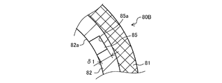
- FIG. 14 is an enlarged schematic cross-sectional view of a peripheral portion including the gap of FIG.
- the bearing 80B of the fourth embodiment has a configuration in which a plurality of voids 85 are provided on the inner peripheral surface 82a of the bearing 80B.
- the gap 85 is composed of recesses formed on the inner peripheral surface 82a.
- the first distance ⁇ 1 (see FIG. 14) between the bottom surface 85a of the recess forming the gap 85 and the inner peripheral surface 82a of the bearing 80B is shown here as an example in which the allowable wear amount is set, but is larger than ⁇ 1. It may be set to a short ⁇ 2.
- the first distance between the bottom surface 85a of the recess forming the gap 85 and the inner peripheral surface 82a of the bearing 80B may be appropriately set according to how much wear is desired to be detected.
- FIG. 15 is a diagram showing an example of a frequency analysis result in a normal state in the compressor system according to the fourth embodiment.
- FIG. 16 is a diagram showing an example of the frequency analysis result at the time of abnormality in the compressor system according to the fourth embodiment.
- an example is shown in which the number of voids 85 in the bearing 80B is three.
- the three voids 85 are in a state of communicating with the inner space of the bearing 80B in the normal state, as shown in FIG. 15, a peak exceeding the set value is obtained at a frequency of 3 ⁇ f. A normal peak with a value is occurring. Then, when the wear of the bearing 80B progresses, the gap provided in the bearing 80B disappears, and the inner peripheral surface 82a of the bearing 80B changes to a flush state over the entire circumference, as shown in FIG. The normal peak at the frequency of f disappears. Therefore, if it is known that the bearing 80B is provided with three voids 85, it means that a wear abnormality has occurred if the peak exceeding the set value does not occur at the frequency of 3 ⁇ f in the frequency analysis result. Can be detected.
- FIG. 17 is a diagram showing an example of a frequency analysis result in a normal state when gaps are provided in both the main bearing and the swing bearing in the compressor system according to the fourth embodiment.
- FIG. 18 is a diagram showing a frequency analysis result when a wear abnormality occurs only in the main bearing in the compressor system according to the fourth embodiment.
- FIG. 19 is a diagram showing a frequency analysis result when a wear abnormality occurs only in the swing bearing in the compressor system according to the fourth embodiment.
- the allowable wear wall thickness portion 82b becomes thinner as the wear progresses. Therefore, if the allowable wear wall thickness portion 82b is not set appropriately, a bearing load is applied. In some cases, the permissible wear wall thickness portion 82b may sink into the void before the permissible amount of wear is reached. Therefore, an abnormal peak may occur before the amount of wear reaches the allowable amount of wear, and the friction abnormality cannot be detected accurately. On the other hand, in the fourth embodiment, since the allowable wear wall thickness portion 82b is not provided in the first place, such a depression can be avoided and the friction abnormality can be accurately detected.
- the fifth embodiment relates to a refrigeration cycle apparatus including the compressor system according to any one of the first to fourth embodiments.
- FIG. 20 is a diagram showing a refrigerant circuit of the refrigeration cycle device according to the fifth embodiment.
- the refrigeration cycle device 300 includes the compressor system according to any one of the first to fourth embodiments.
- the refrigeration cycle device 300 includes a compressor 100, a condenser 301, an expansion valve 302 as a pressure reducing device, and an evaporator 303.
- the gas refrigerant discharged from the compressor 100 of the compressor system flows into the condenser 301, exchanges heat with the air passing through the condenser 301, and flows out as a high-pressure liquid refrigerant.
- the high-pressure liquid refrigerant flowing out of the condenser 301 is depressurized by the expansion valve 302 to become a low-pressure gas-liquid two-phase refrigerant, which flows into the evaporator 303.
- the low-pressure gas-liquid two-phase refrigerant flowing into the evaporator 303 exchanges heat with the air passing through the evaporator 303 to become a low-pressure gas refrigerant, which is again sucked into the compressor 100.
- the refrigeration cycle apparatus 300 configured in this way enables early detection of an abnormal state of the compressor 100, and the compressor is complete. It will be possible to replace it with a new compressor before stopping at. This prevents the refrigeration cycle from stopping and the customer suffering no disadvantage.
- the refrigeration cycle device 300 can be applied to a refrigerator, a freezer, a vending machine, an air conditioner, a water heater, or the like.
Landscapes
- Engineering & Computer Science (AREA)
- Mechanical Engineering (AREA)
- General Engineering & Computer Science (AREA)
- Physics & Mathematics (AREA)
- General Physics & Mathematics (AREA)
- Acoustics & Sound (AREA)
- Applications Or Details Of Rotary Compressors (AREA)
- Measurement Of Length, Angles, Or The Like Using Electric Or Magnetic Means (AREA)
- Compressor (AREA)
Priority Applications (4)
| Application Number | Priority Date | Filing Date | Title |
|---|---|---|---|
| PCT/JP2019/050134 WO2021124557A1 (ja) | 2019-12-20 | 2019-12-20 | 圧縮機システム、圧縮機および冷凍サイクル装置 |
| JP2021565293A JP7204949B2 (ja) | 2019-12-20 | 2019-12-20 | 圧縮機システム、圧縮機および冷凍サイクル装置 |
| US17/767,584 US12135259B2 (en) | 2019-12-20 | 2019-12-20 | Compressor system, compressor, and refrigeration cycle apparatus |
| CN201980101681.1A CN114787577B (zh) | 2019-12-20 | 2019-12-20 | 压缩机系统、压缩机以及制冷循环装置 |
Applications Claiming Priority (1)
| Application Number | Priority Date | Filing Date | Title |
|---|---|---|---|
| PCT/JP2019/050134 WO2021124557A1 (ja) | 2019-12-20 | 2019-12-20 | 圧縮機システム、圧縮機および冷凍サイクル装置 |
Publications (1)
| Publication Number | Publication Date |
|---|---|
| WO2021124557A1 true WO2021124557A1 (ja) | 2021-06-24 |
Family
ID=76478364
Family Applications (1)
| Application Number | Title | Priority Date | Filing Date |
|---|---|---|---|
| PCT/JP2019/050134 Ceased WO2021124557A1 (ja) | 2019-12-20 | 2019-12-20 | 圧縮機システム、圧縮機および冷凍サイクル装置 |
Country Status (4)
| Country | Link |
|---|---|
| US (1) | US12135259B2 (https=) |
| JP (1) | JP7204949B2 (https=) |
| CN (1) | CN114787577B (https=) |
| WO (1) | WO2021124557A1 (https=) |
Families Citing this family (2)
| Publication number | Priority date | Publication date | Assignee | Title |
|---|---|---|---|---|
| WO2024003981A1 (ja) * | 2022-06-27 | 2024-01-04 | 三菱電機株式会社 | スクロール圧縮機 |
| CN116105411B (zh) * | 2023-04-04 | 2023-07-18 | 宁波奥克斯电气股份有限公司 | 压缩机控制方法、装置、空调器及存储介质 |
Citations (6)
| Publication number | Priority date | Publication date | Assignee | Title |
|---|---|---|---|---|
| JPH051880A (ja) * | 1991-06-25 | 1993-01-08 | Matsushita Refrig Co Ltd | 解凍室付き冷蔵庫 |
| JPH08285565A (ja) * | 1995-04-17 | 1996-11-01 | Nikkiso Co Ltd | ベアリングモニタ |
| JP2008075625A (ja) * | 2006-09-25 | 2008-04-03 | Ebara Corp | ポンプ |
| WO2016143186A1 (ja) * | 2015-03-12 | 2016-09-15 | 三菱電機株式会社 | すべり軸受を有する圧縮機 |
| JP2019065828A (ja) * | 2017-10-05 | 2019-04-25 | 株式会社酉島製作所 | ポンプ監視装置、及びポンプ監視方法 |
| JP2019105356A (ja) * | 2017-12-14 | 2019-06-27 | 大豊工業株式会社 | すべり軸受 |
Family Cites Families (9)
| Publication number | Priority date | Publication date | Assignee | Title |
|---|---|---|---|---|
| JPH06100442B2 (ja) | 1990-02-19 | 1994-12-12 | 株式会社前川製作所 | 密閉式回転機械の回転軸部摩耗検出装置 |
| JPH051880U (ja) | 1991-07-01 | 1993-01-14 | 三菱電機株式会社 | スクロール圧縮機 |
| CN105899808B (zh) * | 2014-01-08 | 2017-12-12 | 三菱电机株式会社 | 旋转式压缩机 |
| JP6304194B2 (ja) | 2015-10-27 | 2018-04-04 | ダイキン工業株式会社 | 空気調和機 |
| WO2017175945A1 (en) * | 2016-04-06 | 2017-10-12 | Lg Electronics Inc. | Motor-operated compressor |
| CN107014332B (zh) * | 2017-04-11 | 2023-04-18 | 广东工业大学 | 一种圆盘刀刃口磨损的检测方法及装置 |
| JP6955964B2 (ja) * | 2017-11-01 | 2021-10-27 | 三菱重工コンプレッサ株式会社 | ジャーナル軸受及び回転機械 |
| JP6696533B2 (ja) * | 2018-06-22 | 2020-05-20 | ダイキン工業株式会社 | 冷凍装置 |
| JP2021055648A (ja) * | 2019-10-01 | 2021-04-08 | 株式会社日立産機システム | 流体機械装置 |
-
2019
- 2019-12-20 CN CN201980101681.1A patent/CN114787577B/zh active Active
- 2019-12-20 JP JP2021565293A patent/JP7204949B2/ja active Active
- 2019-12-20 WO PCT/JP2019/050134 patent/WO2021124557A1/ja not_active Ceased
- 2019-12-20 US US17/767,584 patent/US12135259B2/en active Active
Patent Citations (6)
| Publication number | Priority date | Publication date | Assignee | Title |
|---|---|---|---|---|
| JPH051880A (ja) * | 1991-06-25 | 1993-01-08 | Matsushita Refrig Co Ltd | 解凍室付き冷蔵庫 |
| JPH08285565A (ja) * | 1995-04-17 | 1996-11-01 | Nikkiso Co Ltd | ベアリングモニタ |
| JP2008075625A (ja) * | 2006-09-25 | 2008-04-03 | Ebara Corp | ポンプ |
| WO2016143186A1 (ja) * | 2015-03-12 | 2016-09-15 | 三菱電機株式会社 | すべり軸受を有する圧縮機 |
| JP2019065828A (ja) * | 2017-10-05 | 2019-04-25 | 株式会社酉島製作所 | ポンプ監視装置、及びポンプ監視方法 |
| JP2019105356A (ja) * | 2017-12-14 | 2019-06-27 | 大豊工業株式会社 | すべり軸受 |
Also Published As
| Publication number | Publication date |
|---|---|
| US12135259B2 (en) | 2024-11-05 |
| JP7204949B2 (ja) | 2023-01-16 |
| JPWO2021124557A1 (https=) | 2021-06-24 |
| US20230152185A1 (en) | 2023-05-18 |
| CN114787577A (zh) | 2022-07-22 |
| CN114787577B (zh) | 2024-06-25 |
Similar Documents
| Publication | Publication Date | Title |
|---|---|---|
| JP4859730B2 (ja) | スクロール圧縮機 | |
| US9568000B2 (en) | Compressor | |
| CN112166253B (zh) | 制冷装置 | |
| US8246331B2 (en) | Scroll fluid machine with a pin shaft and groove for restricting rotation | |
| JP7204949B2 (ja) | 圧縮機システム、圧縮機および冷凍サイクル装置 | |
| EP2735741B1 (en) | Compressor | |
| JP3864264B2 (ja) | 冷凍空調圧縮機 | |
| CN110168225B (zh) | 压缩机 | |
| WO2019207783A1 (ja) | スクロール圧縮機及びその製造方法 | |
| US11953002B2 (en) | Scroll compressor for compressing a refrigerant and method for oil enrichment and distribution | |
| WO2023104718A1 (en) | A scroll compressor with a load detecting sensor arrangement | |
| JP6575665B2 (ja) | 圧縮機 | |
| EP3559566B1 (en) | Scroll compressor unloading detection system and method thereof | |
| CN112539173A (zh) | 动涡旋盘组件、涡旋压缩机及空调系统 | |
| JP2541352B2 (ja) | スクロ―ル形流体機械 | |
| US20260002533A1 (en) | Rotary compressor and refrigeration apparatus | |
| JP5889142B2 (ja) | スクロール圧縮機 | |
| JP2009042118A (ja) | 継続的摩耗量測定方法 | |
| JP6711136B2 (ja) | スクロール圧縮機 | |
| JP7406916B2 (ja) | 冷凍機用圧縮機 | |
| WO2025258283A1 (ja) | スクイズフィルムダンパ付軸受装置及び遠心圧縮機 | |
| KR20210004541A (ko) | 소음 제어 장치를 구비한 압축기 |
Legal Events
| Date | Code | Title | Description |
|---|---|---|---|
| 121 | Ep: the epo has been informed by wipo that ep was designated in this application |
Ref document number: 19957020 Country of ref document: EP Kind code of ref document: A1 |
|
| ENP | Entry into the national phase |
Ref document number: 2021565293 Country of ref document: JP Kind code of ref document: A |
|
| NENP | Non-entry into the national phase |
Ref country code: DE |
|
| 122 | Ep: pct application non-entry in european phase |
Ref document number: 19957020 Country of ref document: EP Kind code of ref document: A1 |