WO2021111598A1 - モータ駆動装置及び冷凍サイクル装置 - Google Patents
モータ駆動装置及び冷凍サイクル装置 Download PDFInfo
- Publication number
- WO2021111598A1 WO2021111598A1 PCT/JP2019/047663 JP2019047663W WO2021111598A1 WO 2021111598 A1 WO2021111598 A1 WO 2021111598A1 JP 2019047663 W JP2019047663 W JP 2019047663W WO 2021111598 A1 WO2021111598 A1 WO 2021111598A1
- Authority
- WO
- WIPO (PCT)
- Prior art keywords
- motor
- rotation speed
- inverter
- switch
- current
- Prior art date
- Legal status (The legal status is an assumption and is not a legal conclusion. Google has not performed a legal analysis and makes no representation as to the accuracy of the status listed.)
- Ceased
Links
Images


Classifications
-
- H—ELECTRICITY
- H02—GENERATION; CONVERSION OR DISTRIBUTION OF ELECTRIC POWER
- H02P—CONTROL OR REGULATION OF ELECTRIC MOTORS, ELECTRIC GENERATORS OR DYNAMO-ELECTRIC CONVERTERS; CONTROLLING TRANSFORMERS, REACTORS OR CHOKE COILS
- H02P25/00—Arrangements or methods for the control of AC motors characterised by the kind of AC motor or by structural details
- H02P25/16—Arrangements or methods for the control of AC motors characterised by the kind of AC motor or by structural details characterised by the circuit arrangement or by the kind of wiring
- H02P25/18—Arrangements or methods for the control of AC motors characterised by the kind of AC motor or by structural details characterised by the circuit arrangement or by the kind of wiring with arrangements for switching the windings, e.g. with mechanical switches or relays
-
- Y—GENERAL TAGGING OF NEW TECHNOLOGICAL DEVELOPMENTS; GENERAL TAGGING OF CROSS-SECTIONAL TECHNOLOGIES SPANNING OVER SEVERAL SECTIONS OF THE IPC; TECHNICAL SUBJECTS COVERED BY FORMER USPC CROSS-REFERENCE ART COLLECTIONS [XRACs] AND DIGESTS
- Y02—TECHNOLOGIES OR APPLICATIONS FOR MITIGATION OR ADAPTATION AGAINST CLIMATE CHANGE
- Y02B—CLIMATE CHANGE MITIGATION TECHNOLOGIES RELATED TO BUILDINGS, e.g. HOUSING, HOUSE APPLIANCES OR RELATED END-USER APPLICATIONS
- Y02B30/00—Energy efficient heating, ventilation or air conditioning [HVAC]
- Y02B30/70—Efficient control or regulation technologies, e.g. for control of refrigerant flow, motor or heating
Definitions
- the present invention relates to a motor drive device and a refrigeration cycle device for driving a permanent magnet synchronous motor, a so-called open winding motor, which has a plurality of phase windings that are not connected to each other.
- a permanent magnet synchronous motor having multiple phase windings is used as a drive motor for a compressor mounted on a refrigeration cycle device such as an air conditioner or a heat source machine.
- a permanent magnet synchronous motor also referred to as a DC brushless motor
- an open winding motor Open-Windings Motor having a configuration in which a plurality of phase windings are not connected to each other is known.
- the motor drive device that drives this open winding motor (abbreviated as a motor) energizes the first inverter that controls energization of one end of each phase winding of the motor and the other end of each phase winding of the motor.
- a second inverter to be controlled and a switch connected to each other at the other ends of each phase winding are provided, and each phase winding is star-connected (also referred to as a star-shaped connection) by closing the switch.
- the star connection mode In the open winding mode, a high level voltage that is about twice as high as in the star connection mode can be applied to each phase winding.
- the star connection mode In consideration of this point, in the low rotation speed range (also called low / medium rotation speed range) where the rotation speed (speed) of the motor is less than the threshold value, the star connection mode is set so that the rotation speed of the motor becomes the target value. Controls the switching of the first inverter alone.
- the open winding mode In the high rotation speed range where the rotation speed of the motor is equal to or higher than the threshold value, the open winding mode is set, and the switching of the first inverter and the second inverter is controlled in cooperation with each other so that the rotation speed of the motor becomes the target value.
- the motor drive device can switch between the star connection mode and the open winding mode while the motor is being driven. However, if this switching is performed when the motor current suddenly changes, so-called step-out may occur in which the drive control of each inverter and the actual rotation of the motor are not synchronized.
- An object of the embodiment of the present invention is to provide a highly reliable motor drive device and refrigeration cycle device capable of switching between a star connection mode and an open winding mode without causing step-out.
- the motor drive device is a motor drive device for a motor having a plurality of phase windings that are not connected to each other, and is a first inverter that controls energization of one end of each phase winding, and each of the above.
- a second inverter that controls energization of the other end of the phase winding, a switch connected between the other ends of each phase winding, a current detection unit that detects the current flowing through the motor, and the above. It includes a motor controller that controls the opening and closing of a switch and the switching of the first and second inverters. This motor controller prohibits the opening and closing of the switch when the fluctuation range of the detected current of the current detection unit per unit time is equal to or greater than the threshold value.
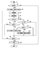
- the figure which shows the structure of the refrigeration cycle apparatus which concerns on one Embodiment The block diagram which shows the structure of one Embodiment. The figure which shows the mode selection condition of one Embodiment. The flowchart which shows the control in the motor controller of one Embodiment.
- FIG. 1 shows the configuration of a refrigeration cycle device such as an air conditioner according to an embodiment.
- One end of the outdoor heat exchanger 3 is connected to the discharge port of the compressor 1 having an open winding motor (Open-Windings Motor) 1M as a driving motor via a four-way valve 2, and the outdoor heat exchanger 3 is connected to the outlet.
- One end of the indoor heat exchanger 5 is connected to the other end by a pipe via an electric expansion valve 4 which is a compressor.
- the other end of the indoor heat exchanger 5 is connected to the suction port of the compressor 1 via the four-way valve 2.
- the outdoor fan 6 is arranged in the vicinity of the outdoor heat exchanger 3, and the indoor fan 7 is arranged in the vicinity of the indoor heat exchanger 5.
- the open winding motor 1M is hereinafter abbreviated as the motor 1M.
- the gas refrigerant discharged from the compressor 1 flows to the outdoor heat exchanger 3 via the four-way valve 2.
- the gas refrigerant flowing through the outdoor heat exchanger 3 releases heat to the outside air and condenses.
- the liquid refrigerant flowing out of the outdoor heat exchanger (condenser) 3 flows to the indoor heat exchanger 5 in a state of being depressurized by the electric expansion valve 4.
- the liquid refrigerant flowing through the indoor heat exchanger 5 takes heat from the indoor air and evaporates.
- the gas refrigerant flowing out of the indoor heat exchanger (evaporator) 5 is sucked into the compressor 1 through the four-way valve 2.
- the flow path of the four-way valve 2 is switched by the controller 10, so that the gas refrigerant discharged from the compressor 1 flows to the indoor heat exchanger 5 via the four-way valve 2 as shown by the arrow. ..
- the gas refrigerant flowing through the indoor heat exchanger 5 releases heat to the indoor air and condenses.
- the liquid refrigerant flowing out of the indoor heat exchanger (condenser) 5 is decompressed by the electric expansion valve 4 and flows to the outdoor heat exchanger 3.
- the liquid refrigerant flowing through the outdoor heat exchanger 3 takes heat from the outside air and evaporates.
- the gas refrigerant flowing out of the outdoor heat exchanger (evaporator) 3 is sucked into the compressor 1 through the four-way valve 2.
- the controller 10 controls the four-way valve 2, the electric expansion valve 4, the outdoor fan 6, and the indoor fan 7, starts and stops the motor drive device 11 of the present embodiment, and sets a room temperature sensor and a temperature setting device (not shown). The required air conditioning capacity is calculated based on the signal from, and this is notified.
- the motor drive device 11 includes the drive circuit 12 and the motor controller 13 shown in FIG.
- the motor 1M is a permanent magnet synchronous motor (three-phase DC brushless motor) having a plurality of, for example, three phase windings Lu, Lv, and Lw that are not connected to each other.
- the phase windings Lu, Lv, and Lw are configured by winding a small-diameter copper wire at a high density so as to improve efficiency in a low rotation speed range (also referred to as a low / medium rotation speed range).
- a low rotation speed range also referred to as a low / medium rotation speed range.
- the small-diameter phase windings Lu, Lv, and Lw are used, the voltage induced in the phase windings Lu, Lv, and Lw rises early as the rotation speed (speed) of the motor 1M increases, and the voltage is induced.
- the motor controller 13 sets a star connection mode in which the phase windings Lu, Lv, and Lw are star-connected (also referred to as star-shaped connection) in the low-speed range and only the inverter 30, which will be described later, is switched independently.
- the phase windings Lu, Lv, Lw are set to a non-connected state (open state), and the inverter 30 and the inverter 40 described later are linked (also referred to as cooperation) to switch with each other to switch the phase windings Lu, Lv, Lw.
- a diode bridge full-wave rectifier circuit 22 is connected to the three-phase AC power supply 20 via a noise filter 21, and a smoothing capacitor 24 is connected to the output end of the full-wave rectifier circuit 22 via a reactor 23.
- the full-wave rectifier circuit 22, the reactor 23, and the smoothing capacitor 24 constitute a DC power supply 25 that outputs a DC voltage Vdc.
- An inverter (first inverter or master inverter) that controls energization of one end of the phase winding Lu, Lv, Lw between the output end of the DC power supply 25 and one end of the phase winding Lu, Lv, Lw of the motor 1M. (Also called) 30 is connected.
- An inverter (second inverter or slave) that controls energization of the other ends of the phase windings Lu, Lv, Lw between the output end of the DC power supply 25 and the other ends of the phase windings Lu, Lv, Lw of the motor 1M. 40 (also called an inverter) is connected.
- a common power supply system is adopted in which the DC power supply 25 is a common DC power supply for the inverters 30 and 40.
- the inverter 30 connects a switching element, for example, the IGBTs 31 and 32 in series, and connects the IGBTs 33 and 34 in series with a U-phase series circuit in which the interconnection point of the IGBTs 31 and 32 is connected to one end of the phase winding Lu of the open winding motor 1M.
- a W-phase series circuit connected to one end of the phase winding Lw of the open winding motor 1M is included, and energization and phase winding Lu from the positive output end of the DC power supply 25 to one end of the phase windings Lu, Lv, Lw. , Lv, Lw
- the energization from one end to the negative output end of the DC power supply 25 is controlled by switching the IGBTs 31 to 36.
- Regenerative diodes (also referred to as freewheel diodes) 31a to 36a are connected in antiparallel to the IGBTs 31 to 36.
- the inverter 40 connects the IGBTs 41 and 42 in series, and connects the IGBTs 43 and 44 in series with a U-phase series circuit in which the interconnection points of the IGBTs 41 and 42 are connected to the other end of the phase winding Lu of the open winding motor 1M.
- the interconnection point of the IGBTs 43 and 44 is connected in series to the IGBT 45 and 46, a V-phase series circuit connected to the other end of the phase winding Lv of the motor 1M, and the interconnection point of the IGBTs 45 and 46 is the open winding motor.
- a W-phase series circuit connected to the other end of the 1M phase winding Lw is connected in parallel to each other, and energization and phase winding from the positive output end of the DC power supply 25 to the other end of the phase windings Lu, Lv, Lw.
- the energization from the other end of Lu, Lv, Lw to the negative output end of the DC power supply 25 is controlled by switching the IGBTs 41 to 46.
- Regenerative diodes (also referred to as freewheel diodes) 41a to 46a are connected in antiparallel to the IGBTs 41 to 46.
- the inverter 30 is actually a peripheral of a main circuit formed by connecting the above three series circuits of U-phase, V-phase, and W-phase in parallel to each other, and a drive circuit for driving the IGBTs 31 to 36 of the main circuit.
- the circuit is a so-called IPM (Intelligent Power Module) in which the circuit is housed in a single package.
- the inverter 40 also uses an IPM having the same configuration.
- a switch, for example, a normally open contact (referred to as a relay contact) 51a of a switch 51 is connected between the other end of the phase winding Lu of the motor 1M and the other end of the phase winding Lv.
- a switch, for example, a normally open contact (referred to as a relay contact) 52a of a switch 52 is connected between the other end of the phase winding Lv of the motor 1M and the other end of the phase winding Lw.
- the relays 51 and 52 are urged and de-energized by the motor controller 13 in a state of being synchronized with each other.
- the relay contacts 51a and 52a When the relay contacts 51a and 52a are closed, the other ends of the phase windings Lu, Lv and Lw are interconnected and the phase windings Lu, Lv and Lw are in a star connection state.
- the interconnection point at the other ends of the phase windings Lu, Lv, and Lw is the neutral point of the star connection.
- the relay contacts 51a and 52a When the relay contacts 51a and 52a are opened, the phase windings Lu, Lv and Lw are in a disconnected state, that is, an electrically separated open winding state.
- the motor controller 13 controls the inverter 30 and the inverter 40 in response to a command from the controller 10, and is the main control unit 60, the voltage detection unit 61, the current detection unit 62, the relay drive unit 63, and the relay, which are the core of the control. Includes 51, 52 and the like.
- the voltage detection unit 61 detects the output voltage (input voltage to the inverters 30 and 40) Vdc of the DC power supply 25.
- the current detection unit 62 detects the currents (referred to as motor currents) Iu, Iv, Iw flowing in the phase windings Lu, Lv, Lw of the motor 1M based on the output signals of the current sensors 53, 53v, 53w.
- the relay drive unit 63 urges and deenergizes the relays 51 and 52 in response to a command from the main control unit 60.
- the main control unit 60 is composed of a microcomputer and its peripheral circuits, and opens and closes the relay contacts 51a and 52a and the inverters 30 and 40 according to a command from the controller 10, detection results of the voltage detection unit 61 and the current detection unit 62, and the like.
- the first control unit 60a, the second control unit 60b, and the third control unit 60c are included.
- the first control unit 60a sets the target rotation speed (target speed) Nt of the motor 1M according to the air conditioning capacity notified from the controller 10, that is, the required capacity as the refrigeration cycle device, and is detected by the current detection unit 62.
- the rotation speed (speed) N of the motor 1M is estimated from the motor currents Iu, Iv, and Iw, and the switching of the inverter 30 is controlled independently in the star connection mode so that the estimated rotation speed N becomes the target rotation speed Nt. In the open winding mode, the switching of the inverters 30 and 40 is controlled in cooperation with each other. Since the capacity of the refrigeration cycle is proportional to the rotation speed of the motor 1M, the target rotation speed Nt of the motor 1M with respect to the required capacity is in a substantially proportional relationship.
- the second control unit 60b has a star connection mode in which the phase windings Lu, Lv, and Lw are star-connected by closing the relay contacts 51a and 52a to switch only the inverter 30 independently, and the relay contacts 51a and 52a are opened.
- the open winding mode in which the inverters 30 and 40 are linked (coordinated) with each other and switched with the phase windings Lu, Lv, and Lw disconnected, is stored in the rotation speed N estimated by the first control unit 60a and the internal memory. It is selectively set by referring to the mode selection condition of FIG.
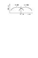
- the vertical axis of FIG. 3 shows the efficiency of the refrigeration cycle.
- the mode selection condition specifies a star connection mode with high refrigeration cycle efficiency when the rotation speed N is in a low rotation speed region less than the second threshold value N2 when the rotation speed N changes in the ascending direction, and the rotation speed N is the second.
- the open winding mode with high refrigeration cycle efficiency is specified when it exists in the high rotation speed range of 2 threshold values N2 or more.
- the mode selection condition specifies the open winding mode when the rotation speed N is in the high rotation speed region exceeding the first threshold value N1 ( ⁇ N2) when the rotation speed N changes in the downward direction, and the rotation speed N is specified.
- Hysteresis is provided by designating the star connection mode when is in the low rotation speed range below the threshold value N1. This enables highly efficient operation over the entire variable rotation speed and prevents frequent mode changes.
- the third control unit 60c detects the fluctuation widths ⁇ Iu, ⁇ Iv, and ⁇ Iw per unit time (1 second to several seconds unit) of the peak values of the motor currents Iu, Iv, and Iw, respectively, and the fluctuation widths of the fluctuation widths ⁇ Iu, ⁇ Iv, and ⁇ Iw. When any of them is equal to or more than the set value ⁇ Is (for example, 1A), or the fluctuation width ⁇ N per unit time of the rotation speed N estimated by the first control unit 60a is detected, and the fluctuation width ⁇ N is the set value ⁇ Ns (for example, 1rps).
- the fluctuation width ⁇ V per unit time of the input voltage Vdc to the inverters 30 and 40 detected by the voltage detection unit 61 is detected and the fluctuation width ⁇ V is the set value ⁇ Vs (for example, 10V) or more. , The opening and closing of the relay contacts 51a and 52a by the second control unit 60b is prohibited.
- the motor controller 13 has a fluctuation range of the motor currents Iu, Iv, and Iw per unit time, respectively, ⁇ Iu, ⁇ Iv, ⁇ Iw, and a fluctuation range of the rotation speed (estimated rotation speed) N of the motor 1M per unit time.
- ⁇ N the fluctuation width ⁇ V per unit time of the input voltage Vdc to the inverters 30 and 40 is detected (S4).
- the motor controller 13 monitors whether or not the rotation speed N of the motor 1M changes in the ascending direction and reaches the threshold value N2 (S5). If the number of revolutions N has risen to the threshold value N2 (YES in S5), the motor controller 13 has the detected fluctuation widths ⁇ Iu, ⁇ Iv, ⁇ Iw less than the set values ⁇ Is (that is, the motor currents Iu, Iv, Iw).
- the detected fluctuation width ⁇ N is less than the set value ⁇ Ns (that is, there is no sudden change in the rotation speed N), and the detected fluctuation width ⁇ V is less than the set value ⁇ Vs (that is, input).
- the open winding mode is set by opening the relay contacts 51a and 52a (YES in S6) on condition that all of the voltage Vdc is not suddenly changed (YES in S6). Sudden changes in the motor currents Iu, Iv, Iw and the rotation speed N occur in response to fluctuations in the air conditioning load. The sudden change in the input voltage Vdc occurs in response to a momentary power failure of the three-phase AC power supply 20 or a sag (temporary decrease).
- the motor controller 13 shifts to the above S3 unless there is an operation stop command from the controller 10 (NO in S8), and the inverter so that the rotation speed N becomes the target rotation speed Nt. 30 and 40 are controlled (S3). If there is an operation stop command (YES in S8), the motor controller 13 deactivates the relays 51 and 52 and stops the inverters 30 and 40 (S12).
- a part of the current path when the open winding mode is set is shown by a broken line in FIG.
- the IGBT 31 in the inverter 30 is turned on and the IGBT 42 in the inverter 40 is repeatedly turned on and off, and the IGBTs 43 and 45 in the inverter 40 are both turned on and the IGBTs 34 and 36 in the inverter 30 are repeatedly turned on and off in synchronization with each other.
- a current flows from the positive output end of the DC power supply 25 through the IGBT 31 to the phase winding Lu, and the current passing through the phase winding Lu passes through the IGBT 42 to the negative of the DC power supply 25.
- a current flows from the positive output end of the DC power supply 25 through the IGBTs 43 and 45 to the phase windings Lv and Lw, and the current passing through the phase windings Lv and Lw passes through the IGBTs 34 and 36. It flows to the negative output end of the DC power supply 25.
- the IGBT 33 in the inverter 30 is turned on and the IGBT 44 in the inverter 40 is repeatedly turned on and off, and the IGBTs 41 and 45 in the inverter 40 are both turned on and the IGBTs 32 and 36 in the inverter 30 are repeatedly turned on and off in synchronization with each other. ..
- a current flows from the positive output end of the DC power supply 25 through the IGBT 33 to the phase winding Lv, and the current passing through the phase winding Lv flows through the IGBT 44 to the negative output end of the DC power supply 25.
- a current flows from the positive output end of the DC power supply 25 through the IGBTs 41 and 45 to the phase windings Lu and Lw, and the current passing through the phase windings Lu and Lw passes through the IGBTs 32 and 36 and outputs to the negative side of the DC power supply 25. It flows to the edge.
- the IGBT 35 in the inverter 30 is turned on and the IGBT 46 in the inverter 40 is repeatedly turned on and off, and the IGBTs 41 and 43 in the inverter 40 are both turned on and the IGBTs 32 and 34 in the inverter 30 are repeatedly turned on and off in synchronization with each other. ..
- a current flows from the positive output end of the DC power supply 25 through the IGBT 35 to the phase winding Lw, and the current passing through the phase winding Lw flows through the IGBT 46 to the negative output end of the DC power supply 25.
- the rotor of the motor 1M rotates.
- any of the fluctuation widths ⁇ Iu, ⁇ Iv, and ⁇ Iw detected in S4 above is greater than or equal to the set value ⁇ Is when the rotation speed N of the motor 1M changes in the ascending direction and reaches the threshold value N2 (YES in S5). (NO in S6), or when the fluctuation width ⁇ N detected in S4 is greater than or equal to the set value ⁇ Ns (NO in S6), or when the fluctuation width ⁇ V detected in S4 is greater than or equal to the set value ⁇ Vs (NO in S6).
- the motor controller 13 bypasses the process of S7 and monitors the operation stop command from the controller 10 in order to prohibit the setting of the open winding mode by opening the relay contacts 51a and 52a (S8). If there is no operation stop command from the controller 10 (NO in S8), the process returns to S3 and controls the inverter 30 so that the rotation speed N becomes the target rotation speed Nt while maintaining the star connection mode setting (S3). ..
- the motor controller 13 has a fluctuation width ⁇ Iu, ⁇ Iv, ⁇ Iw per unit time of the motor currents Iu, Iv, and Iw, and a fluctuation width ⁇ N per unit time of the rotation speed (estimated rotation speed) N of the motor 1M, respectively.
- the fluctuation width ⁇ V per unit time of the input voltage Vdc to the inverters 30 and 40 is detected again (S4).
- the motor controller 13 again monitors whether or not the rotation speed N of the motor 1M changes in the ascending direction and reaches the threshold value N2 (S5). If the rotation speed N has risen to the threshold value N2 (YES in S5), the motor controller 13 indicates that the re-detected fluctuation widths ⁇ Iu, ⁇ Iv, and ⁇ Iw are less than the set values ⁇ Is, and that the re-detected fluctuation width ⁇ N Is less than the set value ⁇ Ns, and the re-detected fluctuation width ⁇ V is less than the set value ⁇ Vs (YES in S6), the relay contacts 51a and 52a are opened to set the open winding mode (the open winding mode is set). S7).
- the relay contacts 51a and 52a are closed and the star connection mode is set on condition that the fluctuation width ⁇ V is less than the set value ⁇ Vs (that is, there is no sudden change in the input voltage Vdc) (YES in S10) (S11). ..
- this star connection mode With the setting of this star connection mode, the motor controller 13 shifts to the above S3 unless there is an operation stop command from the controller 10 (NO in S8), and the inverter 30 is set so that the rotation speed N becomes the target rotation speed Nt. (S3).
- a low level voltage corresponding to low rotation speed operation can be applied to the phase windings Lu, Lv, and Lw.
- any of the fluctuation widths ⁇ Iu, ⁇ Iv, and ⁇ Iw detected in S4 is set.
- the motor controller 13 bypasses the process of S11 and monitors the operation stop command from the controller 10 in order to prohibit the setting of the star connection mode by closing the relay contacts 51a and 52a (S8). If there is no operation stop command from the controller 10 (NO in S8), the process returns to S3 and controls the inverters 30 and 40 so that the rotation speed N becomes the target rotation speed Nt while maintaining the setting of the open winding mode. (S3).
- the motor controller 13 has a fluctuation width ⁇ Iu, ⁇ Iv, ⁇ Iw per unit time of the motor currents Iu, Iv, and Iw, and a fluctuation width ⁇ N per unit time of the rotation speed (estimated rotation speed) N of the motor 1M, respectively.
- the fluctuation width ⁇ V per unit time of the input voltage Vdc to the inverters 30 and 40 is detected again (S4).
- the motor controller 13 again monitors whether the rotation speed N of the motor 1M changes in the downward direction and reaches the threshold value N1 (NO, S9 in S5). If the rotation speed N has decreased to the threshold value N1 (YES in S9), the motor controller 13 means that the redistributed fluctuation widths ⁇ Iu, ⁇ Iv, and ⁇ Iw are less than the set values ⁇ Is, and that the rediscovered fluctuation width ⁇ N Is less than the set value ⁇ Ns, and the re-detected fluctuation width ⁇ V is less than the set value ⁇ Vs (YES in S10), the relay contacts 51a and 52a are closed and the star connection mode is set ( S11).
- the relay contacts 51a are in a state where the switching patterns of the inverters 30 and 40 are appropriately controlled so that no current flows through the relay contacts 51a and 52a.
- 52a is opened and closed.
- the opening and closing of the relay contacts 51a and 52a is prohibited when any of the motor currents Iu, Iv, Iw, the rotation speed N, and the input voltage Vdc suddenly changes, and the motor currents Iu, Iv, Iw, the rotation speed N, and the input voltage are input.
- the relay contacts 51a and 52a By allowing the relay contacts 51a and 52a to open and close when there is no sudden change in any of the voltages Vdc, so-called step-out does not occur in which the drive control of the inverters 30 and 40 and the actual rotation of the motor 1M are not synchronized.
- the current sensors 53u, 53v, 53w were used as the current detection unit 62 to detect the motor current to detect the currents Iu, Iv, Iw flowing in each phase winding, and one of the current sensors, for example, the current sensor 53w. Is removed, and instead, a single current sensor (current transformer) for detecting the total value of the currents Iu, Iv, and Iw flowing in the phase windings Lu, Lv, and Lw is provided, and the removed current sensor 53w is provided.
- the current Iw flowing through the phase winding Lw may be detected by calculation using the detection currents of the remaining current sensors 53u and 53v and the detection currents of the single current sensor.
- a single DC current sensor such as a shunt resistor may be provided in the DC portion of the DC power supply 25, and this DC current sensor may be used as the current detection unit 62 for detecting the motor current.
- the fluctuation range of the motor current is defined as the fluctuation of the peak value, it may be the fluctuation of the effective value or the like. The point is that it is sufficient if the occurrence of large load fluctuations can be detected.
- the current sensors 53u, 53v, 53w are used as the current detection unit 62 to detect the motor current, and the currents Iu, Iv, Iw flowing through each phase winding are detected.
- a single DC current sensor such as a shunt resistor may be provided in the DC portion of the DC power supply 25 to serve as the current detection unit 62 for detecting the motor current.
- the sudden change in the rotation speed N is detected and the switching between the star connection mode and the open winding mode is prohibited.
- the motor controller 13 switches between the open winding mode and the star connection mode in advance, the motor is used.
- the change of the rotation speed of 1M is prohibited, the change of the rotation speed does not occur, so that the change of the rotation speed N may be excluded from the judgment factor of the sudden load change.
- the open winding motor is a motor for driving a compressor
- the same can be applied to an open winding motor used for other applications.
- the common power supply method in which the inverters 30 and 40 are connected to the same DC power supply 25 is adopted, but the same can be implemented in the power supply isolation method in which the inverters 30 and 40 are connected to different DC power supplies.
Landscapes
- Engineering & Computer Science (AREA)
- Power Engineering (AREA)
- Control Of Ac Motors In General (AREA)
Abstract
モータ駆動装置は、互いに非接続状態の複数の相巻線を有するモータのモータ駆動装置であって、上記各相巻線の一端への通電を制御する第1インバータと、上記各相巻線の他端への通電を制御する第2インバータと、上記各相巻線の他端の相互間に接続された開閉器と、上記モータに流れる電流を検出する電流検出部と、上記開閉器の開閉および上記第1および第2インバータのスイッチングを制御するモータコントローラと、を備える。このモータコントローラは、上記電流検出部の検出電流の単位時間当りの変動幅が閾値以上の場合に上記開閉器の開閉を禁止する。
Description
本発明は、互いに非接続状態の複数の相巻線を有する永久磁石同期モータいわゆるオープン巻線モータを駆動するモータ駆動装置及び冷凍サイクル装置に関する。
空気調和機や熱源機などの冷凍サイクル装置に搭載される圧縮機の駆動用モータとして、複数の相巻線を有する永久磁石同期モータが使用される。また、永久磁石同期モータ(DCブラシレスモータともいう)の一例として、複数の相巻線を互いに非接続状態とした構成のオープン巻線モータ(Open-Windings Motor)が知られている。
このオープン巻線モータ(モータと略称する)を駆動するモータ駆動装置は、モータの各相巻線の一端への通電を制御する第1インバータ、モータの各相巻線の他端への通電を制御する第2インバータ、各相巻線の他端の相互間に接続される開閉器を備え、この開閉器の閉成により各相巻線をスター結線(星形結線ともいう)して第1インバータのみを単独でスイッチングするスター結線モード、および開閉器の開放により各相巻線を非接続状態として第1インバータおよび第2インバータを互いに連係してスイッチングするオープン巻線モードを、選択的に設定する。
オープン巻線モードでは、スター結線モード時の約2倍の高レベルの電圧を各相巻線に印加することができる。この点を考慮し、モータの回転数(速度)が閾値未満の低回転数域(低・中回転数域ともいう)では、スター結線モードを設定し、モータの回転数が目標値となるよう第1インバータの単独のスイッチングを制御する。モータの回転数が閾値以上の高回転数域では、オープン巻線モードを設定し、モータの回転数が目標値となるよう第1インバータおよび第2インバータのスイッチングを互いに連係して制御する。このようにスター結線モードとオープン巻線モードを切換えることで、低回転数域から高回転数域まで幅広い回転数範囲で高効率の運転を行うことができる。
上記モータ駆動装置は、モータの駆動中にスター結線モードとオープン巻線モードを切換えることが可能である。ただし、モータ電流の急変時にこの切換えが行われると、各インバータの駆動制御とモータの実際の回転とが同期しなくなるいわゆる脱調が生じるおそれがある。
オープン巻線モータを圧縮機の駆動用モータとして用いる冷凍サイクル装置たとえば空気調和機の場合、脱調が生じると、一旦運転を停止し、圧縮機を再駆動しなければならない。圧縮機の再起動には、冷凍サイクルの高低圧がバランスするまでの数分間の時間を要し、この間、空調ができなくなる。また、脱調時に大きな電流がモータ巻線に流れると回転子に設けられている永久磁石が減磁してしまうおそれもある。
本発明の実施形態の目的は、脱調を生じることなくスター結線モードとオープン巻線モードを切換えることができる信頼性にすぐれたモータ駆動装置及び冷凍サイクル装置を提供することである。
請求項1のモータ駆動装置は、互いに非接続状態の複数の相巻線を有するモータのモータ駆動装置であって、前記各相巻線の一端への通電を制御する第1インバータと、前記各相巻線の他端への通電を制御する第2インバータと、前記各相巻線の他端の相互間に接続された開閉器と、前記モータに流れる電流を検出する電流検出部と、前記開閉器の開閉および前記第1および第2インバータのスイッチングを制御するモータコントローラと、を備える。このモータコントローラは、前記電流検出部の検出電流の単位時間当りの変動幅が閾値以上の場合に前記開閉器の開閉を禁止する。
一実施形態について説明する。一実施形態に係る空気調和機等の冷凍サイクル装置の構成を図1に示す。
オープン巻線モータ(Open-Windings Motor)1Mを駆動用モータとして有する圧縮機1の吐出口に、四方弁2を介して室外熱交換器3の一端が配管接続され、その室外熱交換器3の他端に減圧器である電動膨張弁4を介して室内熱交換器5の一端が配管接続されている。そして、室内熱交換器5の他端が上記四方弁2を介して圧縮機1の吸込口に配管接続されている。室外熱交換器3の近傍に室外ファン6が配置され、室内熱交換器5の近傍に室内ファン7が配置されている。オープン巻線モータ1Mのことを、以下、モータ1Mと略称する。
冷房運転時は、実線矢印で示すように、圧縮機1から吐出されるガス冷媒が四方弁2を介して室外熱交換器3に流れる。室外熱交換器3に流れたガス冷媒は、外気に熱を放出して凝縮する。この室外熱交換器(凝縮器)3から流出する液冷媒は、電動膨張弁4で減圧された状態で室内熱交換器5に流れる。室内熱交換器5に流れた液冷媒は、室内空気から熱を奪って蒸発する。この室内熱交換器(蒸発器)5から流出するガス冷媒は、四方弁2を通って圧縮機1に吸い込まれる。暖房運転時は、コントローラ10によって四方弁2の流路が切換えられることにより、破線矢印で示すように、圧縮機1から吐出されるガス冷媒が四方弁2を介して室内熱交換器5に流れる。室内熱交換器5に流れたガス冷媒は、室内空気に熱を放出して凝縮する。この室内熱交換器(凝縮器)5から流出する液冷媒は、電動膨張弁4で減圧されて室外熱交換器3に流れる。室外熱交換器3に流れた液冷媒は、外気から熱を奪って蒸発する。この室外熱交換器(蒸発器)3から流出するガス冷媒は、四方弁2を通って圧縮機1に吸い込まれる。
コントローラ10は、四方弁2、電動膨張弁4、室外ファン6、および室内ファン7を制御するとともに、本実施形態のモータ駆動装置11に対して運転・停止、及び図示しない室温センサや温度設定器からの信号に基づき必要な空調能力を算出し、これを通知する。モータ駆動装置11は、図2に示す駆動回路12およびモータコントローラ13を含む。
モータ1Mは、互いに非接続状態の複数たとえば3つの相巻線Lu,Lv,Lwを有する永久磁石同期モータ(三相DCブラシレスモータ)である。相巻線Lu,Lv,Lwは、低回転数域(低・中回転数域ともいう)で効率が向上するよう、細径の銅線を高い密度で巻回して構成される。ただし、細径の相巻線Lu,Lv,Lwを用いると、モータ1Mの回転数(速度)の上昇に伴って相巻線Lu,Lv,Lwに誘起する電圧が早期に上昇し、その誘起電圧と後述のインバータから相巻線Lu,Lv,Lwに供給される電圧との差が早い段階で小さくなり、それ以上はモータ1Mの回転数を上昇させることができなくなる。そこで、モータコントローラ13は、低回転数域では相巻線Lu,Lv,Lwをスター結線(星形結線ともいう)して後述のインバータ30のみを単独でスイッチングするスター結線モードを設定し、高回転数域では相巻線Lu,Lv,Lwを非接続状態(オープン状態)としてインバータ30および後述のインバータ40を互いに連係(協調ともいう)してスイッチングすることで相巻線Lu,Lv,Lwへの印加電圧を高めて運転するオープン巻線モードを設定する。この設定により、低回転数域では1つのインバータ30のみを使用し、インバータ40を使用しないことでその分の損失も低減して高効率の運転を可能としながら、その低回転数域から高回転数域まで幅広い回転数範囲で高効率の運転を行うことが可能である。
[駆動回路12の説明]
3相交流電源20にノイズフィルタ21を介してダイオードブリッジの全波整流回路22が接続され、その全波整流回路22の出力端にリアクタ23を介して平滑コンデンサ24が接続されている。この全波整流回路22、リアクタ23、平滑コンデンサ24により、直流電圧Vdcを出力する直流電源25が構成される。
3相交流電源20にノイズフィルタ21を介してダイオードブリッジの全波整流回路22が接続され、その全波整流回路22の出力端にリアクタ23を介して平滑コンデンサ24が接続されている。この全波整流回路22、リアクタ23、平滑コンデンサ24により、直流電圧Vdcを出力する直流電源25が構成される。
この直流電源25の出力端とモータ1Mの相巻線Lu,Lv,Lwの一端との間に、相巻線Lu,Lv,Lwの一端への通電を制御するインバータ(第1インバータまたはマスタインバータともいう)30が接続されている。直流電源25の出力端とモータ1Mの相巻線Lu,Lv,Lwの他端との間に、相巻線Lu,Lv,Lwの他端への通電を制御するインバータ(第2インバータまたはスレーブインバータともいう)40が接続されている。直流電源25をインバータ30,40の共通の直流電源とする電源共通方式を採用している。
インバータ30は、スイッチング素子たとえばIGBT31,32を直列接続し、そのIGBT31,32の相互接続点がオープン巻線モータ1Mの相巻線Luの一端に接続されるU相直列回路、IGBT33,34を直列接続し、そのIGBT33,34の相互接続点がオープン巻線モータ1Mの相巻線Lvの一端に接続されるV相直列回路、IGBT35,36を直列接続し、そのIGBT35,36の相互接続点がオープン巻線モータ1Mの相巻線Lwの一端に接続されるW相直列回路を含み、直流電源25の正側出力端から相巻線Lu,Lv,Lwの一端への通電および相巻線Lu,Lv,Lwの一端から直流電源25の負側出力端への通電をIGBT31~36のスイッチングにより制御する。IGBT31~36には、回生用ダイオード(フリー・ホイール・ダイオードともいう)31a~36aが逆並列接続されている。
インバータ40は、IGBT41,42を直列接続し、そのIGBT41,42の相互接続点がオープン巻線モータ1Mの相巻線Luの他端に接続されるU相直列回路、IGBT43,44を直列接続し、そのIGBT43,44の相互接続点がモータ1Mの相巻線Lvの他端に接続されるV相直列回路、IGBT45,46を直列接続し、そのIGBT45,46の相互接続点がオープン巻線モータ1Mの相巻線Lwの他端に接続されるW相直列回路を互いに並列接続し、直流電源25の正側出力端から相巻線Lu,Lv,Lwの他端への通電および相巻線Lu,Lv,Lwの他端から直流電源25の負側出力端への通電をIGBT41~46のスイッチングにより制御する。IGBT41~46には、回生用ダイオード(フリー・ホイール・ダイオードともいう)41a~46aが逆並列接続されている。
なお、インバータ30は、実際には、U相・V相・W相の上記3つの直列回路を互いに並列接続してなる主回路と、この主回路のIGBT31~36を駆動する駆動回路などの周辺回路とを、単一のパッケージに収納したモジュールいわゆるIPM(Intelligent Power Module)である。インバータ40も、同様の構成のIPMが使用される。
モータ1Mの相巻線Luの他端と相巻線Lvの他端との相互間に、開閉器たとえばリレー51の常開形接点(リレー接点という)51aが接続されている。モータ1Mの相巻線Lvの他端と相巻線Lwの他端との相互間に、開閉器たとえばリレー52の常開形接点(リレー接点という)52aが接続されている。リレー51,52は、モータコントローラ13により、互いに同期した状態で付勢と消勢が制御される。リレー接点51a,52aが閉成すると、相巻線Lu,Lv,Lwの他端が相互接続されて相巻線Lu,Lv,Lwがスター結線状態となる。相巻線Lu,Lv,Lwの他端の相互接続点がスター結線の中性点となる。リレー接点51a,52aが開放すると、相巻線Lu,Lv,Lwが非接続状態つまり電気的に分離したオープン巻線状態となる。
インバータ30と相巻線Lu,Lv,Lwの一端との間の3つの通電ラインに電流センサ53u,53v,53wが配置され、これら電流センサ53u,53v,53wの出力信号がモータコントローラ13に送られる。モータコントローラ13は、コントローラ10からの指令に応じてインバータ30及びインバータ40を制御するもので、制御の中枢となる主制御部60、電圧検出部61、電流検出部62、リレー駆動部63、リレー51,52などを含む。電圧検出部61は、直流電源25の出力電圧(インバータ30,40への入力電圧)Vdcを検出する。電流検出部62は、モータ1Mの相巻線Lu,Lv,Lwに流れる電流(モータ電流という)Iu,Iv,Iwを電流センサ53,53v,53wの出力信号に基づき検出する。リレー駆動部63は、主制御部60からの指令に応じてリレー51,52を付勢および消勢する。
主制御部60は、マイクロコンピュータおよびその周辺回路により構成され、コントローラ10からの指令、電圧検出部61および電流検出部62の検出結果などに応じてリレー接点51a,52aの開閉およびインバータ30,40のスイッチングを制御するもので、第1制御部60a、第2制御部60b、第3制御部60cを含む。
第1制御部60aは、コントローラ10から通知される空調能力、すなわち冷凍サイクル装置としての要求能力に応じてモータ1Mの目標回転数(目標速度)Ntを設定するとともに、電流検出部62で検出されるモータ電流Iu,Iv,Iwからモータ1Mの回転数(速度)Nを推定し、推定した回転数Nが目標回転数Ntとなるよう、スター結線モード時はインバータ30の単独のスイッチングを制御し、オープン巻線モード時はインバータ30,40のスイッチングを互いに連携して制御する。なお、冷凍サイクルの能力は、モータ1Mの回転数に比例するため、要求能力に対するモータ1Mの目標回転数Ntは、略比例関係にある。
第2制御部60bは、リレー接点51a,52aの閉成により相巻線Lu,Lv,Lwをスター結線してインバータ30のみを単独でスイッチングするスター結線モード、およびリレー接点51a,52aの開放により相巻線Lu,Lv,Lwを非接続状態としてインバータ30,40を互いに連係(協調)してスイッチングするオープン巻線モードを、第1制御部60aで推定される回転数Nおよび内部メモリに記憶している図3のモード選択条件を参照することで選択的に設定する。なお、図3の縦軸は冷凍サイクルの効率を示す。
モード選択条件は、回転数Nの上昇方向の変化に際し、回転数Nが第2閾値N2未満の低回転数域に存する場合に冷凍サイクル効率の高いスター結線モードを指定し、回転数Nが第2閾値N2以上の高回転数域に存する場合に冷凍サイクル効率の高いオープン巻線モードを指定する。さらに、モード選択条件は、回転数Nの下降方向の変化に際し、回転数Nが第1閾値N1(<N2)超の高回転数域に存する場合にオープン巻線モードを指定し、回転数Nが閾値N1以下の低回転数域に存する場合にスター結線モードを指定することでヒステリシスを設けている。これによって回転数可変幅の全体にわたって高効率な運転が可能になるとともに、頻繁なモード変更を防止している。
第3制御部60cは、モータ電流Iu,Iv,Iwのピーク値のそれぞれ単位時間(1秒から数秒単位)当りの変動幅ΔIu,ΔIv,ΔIwを検出し、その変動幅ΔIu,ΔIv,ΔIwのいずれかが設定値ΔIs(例えば1A)以上の場合、または第1制御部60aで推定される回転数Nの単位時間当りの変動幅ΔNを検出し、その変動幅ΔNが設定値ΔNs(例えば1rps)以上の場合、または電圧検出部61で検出されるインバータ30,40への入力電圧Vdcの単位時間当りの変動幅ΔVを検出し、その変動幅ΔVが設定値ΔVs(例えば10V)以上の場合、第2制御部60bによるリレー接点51a,52aの開閉を禁止する。
つぎに、モータコントローラ13が実行する制御を図4のフローチャートを参照しながら説明する。フローチャート中のステップS1,S2…については単にS1,S2…と略称する。
[スター結線モードからオープン巻線モードへの切換え]
コントローラ10から運転開始指令を受けた場合(S1のYES)、モータコントローラ13は、リレー接点51a,52aを閉成して相巻線Lu,Lv,Lwの他端を相互接続しかつインバータ30を単独でスイッチングするスター結線モードを設定する(S2)。この設定に伴い、モータコントローラ13は、コントローラ10から通知される空調負荷に応じてモータ1Mの目標回転数(目標速度)Ntを設定し、かつ電流検出部62で検出されるモータ電流Iu,Iv,Iwからモータ1Mの回転数(速度)Nを推定し、推定した回転数Nが目標回転数Ntとなるようインバータ30のスイッチングをPWM制御(パルス幅変調制御)する(S3)。
コントローラ10から運転開始指令を受けた場合(S1のYES)、モータコントローラ13は、リレー接点51a,52aを閉成して相巻線Lu,Lv,Lwの他端を相互接続しかつインバータ30を単独でスイッチングするスター結線モードを設定する(S2)。この設定に伴い、モータコントローラ13は、コントローラ10から通知される空調負荷に応じてモータ1Mの目標回転数(目標速度)Ntを設定し、かつ電流検出部62で検出されるモータ電流Iu,Iv,Iwからモータ1Mの回転数(速度)Nを推定し、推定した回転数Nが目標回転数Ntとなるようインバータ30のスイッチングをPWM制御(パルス幅変調制御)する(S3)。
このPWM制御に伴い、モータコントローラ13は、モータ電流Iu,Iv,Iwのそれぞれ単位時間当りの変動幅ΔIu,ΔIv,ΔIw、モータ1Mの回転数(推定回転数)Nの単位時間当りの変動幅ΔN、インバータ30,40への入力電圧Vdcの単位時間当りの変動幅ΔVを検出する(S4)。
続いて、モータコントローラ13は、モータ1Mの回転数Nが上昇方向に変化して閾値N2に達したか否かを監視する(S5)。回転数Nが閾値N2まで上昇していれば(S5のYES)、モータコントローラ13は、上記検出した変動幅ΔIu,ΔIv,ΔIwが設定値ΔIs未満であること(つまりモータ電流Iu,Iv,Iwの急変がないこと)、上記検出した変動幅ΔNが設定値ΔNs未満であること(つまり回転数Nの急変がないこと)、上記検出した変動幅ΔVが設定値ΔVs未満であること(つまり入力電圧Vdcの急変がないこと)のすべてが満たされることを条件に(S6のYES)、リレー接点51a,52aを開放してオープン巻線モードを設定する(S7)。モータ電流Iu,Iv,Iwや回転数Nの急変は、空調負荷の変動など応じて生じる。入力電圧Vdcの急変は、3相交流電源20の瞬時停電やサグ(Sag;一時低下)などに応じて生じる。
このオープン巻線モードの設定に伴い、モータコントローラ13は、コントローラ10からの運転停止指令がなければ(S8のNO)、上記S3に移行し、回転数Nが目標回転数Ntとなるよう、インバータ30,40を制御する(S3)。運転停止指令があれば(S8のYES)、モータコントローラ13は、リレー51,52を消勢するとともにインバータ30,40を停止する(S12)。
オープン巻線モードが設定された場合の電流経路の一部を図2に破線で示している。まず、インバータ30におけるIGBT31がオンしてインバータ40におけるIGBT42がオン,オフを繰返すとともに、インバータ40におけるIGBT43,45が共にオンしてインバータ30におけるIGBT34,36が互いに同期してオン,オフを繰返す。これにより、破線矢印で示すように、直流電源25の正側出力端からIGBT31を通って相巻線Luに電流が流れ、その相巻線Luを経た電流がIGBT42を通って直流電源25の負側出力端に流れるとともに、直流電源25の正側出力端からIGBT43,45を通って相巻線Lv,Lwに電流が流れ、その相巻線Lv,Lwを経た電流がIGBT34,36を通って直流電源25の負側出力端に流れる。次に、インバータ30におけるIGBT33がオンしてインバータ40におけるIGBT44がオン,オフを繰返すとともに、インバータ40におけるIGBT41,45が共にオンしてインバータ30におけるIGBT32,36が互いに同期してオン,オフを繰返す。これにより、直流電源25の正側出力端からIGBT33を通って相巻線Lvに電流が流れ、その相巻線Lvを経た電流がIGBT44を通って直流電源25の負側出力端に流れるとともに、直流電源25の正側出力端からIGBT41,45を通って相巻線Lu,Lwに電流が流れ、その相巻線Lu,Lwを経た電流がIGBT32,36を通って直流電源25の負側出力端に流れる。次に、インバータ30におけるIGBT35がオンしてインバータ40におけるIGBT46がオン,オフを繰返すとともに、インバータ40におけるIGBT41,43が共にオンしてインバータ30におけるIGBT32,34が互いに同期してオン,オフを繰返す。これにより、直流電源25の正側出力端からIGBT35を通って相巻線Lwに電流が流れ、その相巻線Lwを経た電流がIGBT46を通って直流電源25の負側出力端に流れるとともに、直流電源25の正側出力端からIGBT41,43を通って相巻線Lu,Lvに電流が流れ、その相巻線Lu,Lvを経た電流がIGBT32,34を通って直流電源25の負側出力端に流れる。これら3パターンの電流経路が順に切換わることにより、モータ1Mのロータが回転する。
このオープン巻線モードの設定により、スター結線モード時の約√3倍の電圧を相巻線Lu,Lv,Lwに印加することができ、モータ1Mおける逆起電力に打ち勝ってモータ1Mを高回転で運転することが可能となる。空気調和機の運転開始時は空調負荷が大きいので、モータ1Mの高回転数運転が必要な状況にあることが多い。このため、空気調和機の運転開始時は、スター結線モードからオープン巻線モードに切換わる流れとなる。
ただし、モータ1Mの回転数Nが上昇方向に変化して閾値N2に達した際に(S5のYES)、上記S4で検出した変動幅ΔIu,ΔIv,ΔIwのいずれかが設定値ΔIs以上の場合(S6のNO)、または上記S4で検出した変動幅ΔNが設定値ΔNs以上の場合(S6のNO)、または上記S4で検出した変動幅ΔVが設定値ΔVs以上の場合(S6のNO)、モータコントローラ13は、リレー接点51a,52aの開放によるオープン巻線モードの設定を禁止するべく、上記S7の処理を迂回してコントローラ10からの運転停止指令を監視する(S8)。コントローラ10からの運転停止指令がなければ(S8のNO)、上記S3に戻り、スター結線モードの設定を維持したまま、回転数Nが目標回転数Ntとなるようインバータ30を制御する(S3)。
この制御に伴い、モータコントローラ13は、モータ電流Iu,Iv,Iwのそれぞれ単位時間当りの変動幅ΔIu,ΔIv,ΔIw、モータ1Mの回転数(推定回転数)Nの単位時間当りの変動幅ΔN、インバータ30,40への入力電圧Vdcの単位時間当りの変動幅ΔVを再び検出する(S4)。
続いて、モータコントローラ13は、モータ1Mの回転数Nが上昇方向に変化して閾値N2に達したか否かを再び監視する(S5)。回転数Nが閾値N2まで上昇していれば(S5のYES)、モータコントローラ13は、上記再検出した変動幅ΔIu,ΔIv,ΔIwが設定値ΔIs未満であること、上記再検出した変動幅ΔNが設定値ΔNs未満であること、上記再検出した変動幅ΔVが設定値ΔVs未満であることを条件に(S6のYES)、リレー接点51a,52aを開放してオープン巻線モードを設定する(S7)。
[オープン巻線モードからスター結線モードへの切換え]
回転数Nが下降方向に変化して閾値N1に達した場合(S5のNO,S9のYES)、モータコントローラ13は、上記S4で検出した変動幅ΔIu,ΔIv,ΔIwが設定値ΔIs未満であること(つまりモータ電流Iu,Iv,Iwの急変がないこと)、上記S4で検出した変動幅ΔNが設定値ΔNs未満であること(つまり回転数Nの急変がないこと)、上記S4で検出した変動幅ΔVが設定値ΔVs未満であること(つまり入力電圧Vdcの急変がないこと)を条件に(S10のYES)、リレー接点51a,52aを閉成してスター結線モードを設定する(S11)。
回転数Nが下降方向に変化して閾値N1に達した場合(S5のNO,S9のYES)、モータコントローラ13は、上記S4で検出した変動幅ΔIu,ΔIv,ΔIwが設定値ΔIs未満であること(つまりモータ電流Iu,Iv,Iwの急変がないこと)、上記S4で検出した変動幅ΔNが設定値ΔNs未満であること(つまり回転数Nの急変がないこと)、上記S4で検出した変動幅ΔVが設定値ΔVs未満であること(つまり入力電圧Vdcの急変がないこと)を条件に(S10のYES)、リレー接点51a,52aを閉成してスター結線モードを設定する(S11)。
このスター結線モードの設定に伴い、モータコントローラ13は、コントローラ10からの運転停止指令がなければ(S8のNO)、上記S3に移行し、回転数Nが目標回転数Ntとなるよう、インバータ30を制御する(S3)。このスター結線モードの設定により、低回転数運転に対応する低レベルの電圧を相巻線Lu,Lv,Lwに印加することができる。
ただし、モータ1Mの回転数Nが下降方向に変化して閾値N1に達した際に(S5のNO,S9のNO)、上記S4で検出した変動幅ΔIu,ΔIv,ΔIwのいずれかが設定値ΔIs以上の場合(S10のNO)、または上記S4で検出した変動幅ΔNが設定値ΔNs以上の場合(S10のNO)、または上記S4で検出した変動幅ΔVが設定値ΔVs以上の場合(S10のNO)、モータコントローラ13は、リレー接点51a,52aの閉成によるスター結線モードの設定を禁止するべく、上記S11の処理を迂回してコントローラ10からの運転停止指令を監視する(S8)。コントローラ10からの運転停止指令がなければ(S8のNO)、上記S3に戻り、オープン巻線モードの設定を維持したまま、回転数Nが目標回転数Ntとなるようインバータ30、40を制御する(S3)。
この制御に伴い、モータコントローラ13は、モータ電流Iu,Iv,Iwのそれぞれ単位時間当りの変動幅ΔIu,ΔIv,ΔIw、モータ1Mの回転数(推定回転数)Nの単位時間当りの変動幅ΔN、インバータ30,40への入力電圧Vdcの単位時間当りの変動幅ΔVを再び検出する(S4)。
続いて、モータコントローラ13は、モータ1Mの回転数Nが下降方向に変化して閾値N1に達したかいなかを再び監視する(S5のNO,S9)。回転数Nが閾値N1まで下降していれば(S9のYES)、モータコントローラ13は、上記再検出した変動幅ΔIu,ΔIv,ΔIwが設定値ΔIs未満であること、上記再検出した変動幅ΔNが設定値ΔNs未満であること、上記再検出した変動幅ΔVが設定値ΔVs未満であることを条件に(S10のYES)、リレー接点51a,52aを閉成してスター結線モードを設定する(S11)。
なお、モータコントローラ13は、スター結線モードとオープン巻線モードの相互の切換えに際し、リレー接点51a,52aに電流が流れないようにインバータ30,40のスイッチングパターンを適切に制御した状態でリレー接点51a,52aを開閉する。リレー接点51a,52aに電流が流れない状態でリレー接点51a,52aを開閉することにより、リレー接点51a,52aにおける火花の発生等を防ぐことができ、ひいてはリレー接点51a,52aの溶着等の故障を回避できる。
[まとめ]
以上のように、モータ電流Iu,Iv,Iw、回転数N、入力電圧Vdcのいずれかの急変に際してリレー接点51a,52aの開閉を禁止し、モータ電流Iu,Iv,Iw、回転数N、入力電圧Vdcのいずれにも急変がない場合にリレー接点51a,52aの開閉を許容することにより、インバータ30,40の駆動制御とモータ1Mの実際の回転とが同期しなくなるいわゆる脱調が生じない。脱調によるモータ1Mの不要な停止を生じることなく、ひいては圧縮機1の運転の不要な停止を生じることなく、スター結線モードとオープン巻線モードを切換えることができる
[変形例]
上記実施形態では、開閉器がリレー接点51a,52aである場合を例に説明したが、半導体スイッチを開閉器として用いてもよい。
以上のように、モータ電流Iu,Iv,Iw、回転数N、入力電圧Vdcのいずれかの急変に際してリレー接点51a,52aの開閉を禁止し、モータ電流Iu,Iv,Iw、回転数N、入力電圧Vdcのいずれにも急変がない場合にリレー接点51a,52aの開閉を許容することにより、インバータ30,40の駆動制御とモータ1Mの実際の回転とが同期しなくなるいわゆる脱調が生じない。脱調によるモータ1Mの不要な停止を生じることなく、ひいては圧縮機1の運転の不要な停止を生じることなく、スター結線モードとオープン巻線モードを切換えることができる
[変形例]
上記実施形態では、開閉器がリレー接点51a,52aである場合を例に説明したが、半導体スイッチを開閉器として用いてもよい。
また、モータ電流を検出する電流検出部62として電流センサ53u,53v,53wを用いて各相巻線に流れる電流Iu,Iv,Iwを検出したが、この内の1つの電流センサたとえば電流センサ53wを除去し、その代わりに相巻線Lu,Lv,Lwに流れる電流Iu,Iv,Iwの合算値を検出する単一の電流センサ(カレントトランス)を設け、除去した電流センサ53wが設けられていた相巻線Lwに流れる電流Iwについては、残りの電流センサ53u,53vの検知電流と上記単一の電流センサの検知電流とを用いる計算により検出する構成としてもよい。さらに、直流電源25の直流部にシャント抵抗などの単一の直流電流センサを設け、この直流電流センサをモータ電流検出用の電流検出部62としてもよい。また、モータ電流の変動幅をピーク値の変動としたが、実効値等の変動としてもよい。要は大きな負荷変動の発生を検出できればよい
また、モータ電流を検出する電流検出部62として電流センサ53u,53v,53wを用いて各相巻線に流れる電流Iu,Iv,Iwを検出したが、直流電源25の直流部にシャント抵抗などの単一の直流電流センサを設け、これによりモータ電流を検出する電流検出部62としてもよい。
また、モータ電流を検出する電流検出部62として電流センサ53u,53v,53wを用いて各相巻線に流れる電流Iu,Iv,Iwを検出したが、直流電源25の直流部にシャント抵抗などの単一の直流電流センサを設け、これによりモータ電流を検出する電流検出部62としてもよい。
なお、上記実施形態では、回転数Nの急変を検出してスター結線モードとオープン巻線モードの切換えを禁止したが、モータコントローラ13がオープン巻線モードとスター結線モードとの相互切換え時に予めモータ1Mの回転数変更を禁止するようにした場合には、回転数の変動は発生しないため、回転数Nの変化は負荷急変の判断要素から除外してもよい。
上記実施形態では、オープン巻線モータの用途が圧縮機の駆動用モータである場合を例に説明したが、他の用途に用いるオープン巻線モータについても同様に実施できる。
上記実施形態では、インバータ30,40を同じ直流電源25に接続する電源共通方式を採用したが、インバータ30,40を別々の直流電源に接続する電源絶縁方式においても、同様に実施できる。
その他、上記各実施形態および変形例は、例として提示したものであり、発明の範囲を限定することは意図していない。この新規な各実施形態および変形例は、その他の様々な形態で実施されることが可能であり、発明の要旨を逸脱しない範囲で、種々の省略、書き換え、変更を行うことができる。これら実施形態や変形は、発明の範囲は要旨に含まれるとともに、特許請求の範囲に記載された発明とその均等の範囲に含まれる。
1…圧縮機、1M…オープン巻線モータ、Lu,Lv,Lw…相巻線、2…四方弁、3…室外熱交換器、4…電動膨張弁、5…室内熱交換器、10…コントローラ、11…モータ駆動装置、12…駆動回路、13…モータコントローラ、20…3相交流電源、25…直流電源、30…インバータ(第1インバータ)、40…インバータ(第2インバータ)、51,52…リレー、51a,52a…リレー接点、60…主制御部、61…電圧検出部、62…電流検出部、63…リレー駆動部
Claims (7)
- 互いに非接続状態の複数の相巻線を有するモータのモータ駆動装置であって、
前記各相巻線の一端への通電を制御する第1インバータと、
前記各相巻線の他端への通電を制御する第2インバータと、
前記各相巻線の他端の相互間に接続された開閉器と、
前記モータに流れる電流を検出する電流検出部と、
前記開閉器の開閉および前記第1および第2インバータのスイッチングを制御するモータコントローラと、
を備え、
前記モータコントローラは、前記電流検出部の検出電流の単位時間当りの変動幅が閾値以上の場合に前記開閉器の開閉を禁止する、
ことを特徴とするモータ駆動装置。 - さらに、前記第1および第2インバータへの入力電圧を検出する電圧検出部を備え、
前記モータコントローラは、前記電流検出部の検出電流の単位時間当りの変動幅が設定値以上の場合、または前記電圧検出部の検出電圧の単位時間当りの変動幅が設定値以上の場合に、前記開閉器の開閉を禁止する、
ことを特徴とする請求項1に記載のモータ駆動装置。 - さらに、前記第1および第2インバータへの入力電圧を検出する電圧検出部を備え、
前記モータコントローラは、前記電流検出部の検出電流の単位時間当りの変動幅が設定値以上の場合、または前記モータの回転数の単位時間当りの変動幅が設定値以上の場合、または前記電圧検出部の検出電圧の単位時間当りの変動幅が設定値以上の場合に、前記開閉器の開閉を禁止する、
ことを特徴とする請求項1に記載のモータ駆動装置。 - 前記モータコントローラは、前記開閉器の閉成により前記各相巻線の他端を相互接続して前記第1インバータを単独でスイッチングするスター結線モード、および前記開閉器の開放により前記各相巻線の他端を非接続状態として前記第1および第2インバータを互いに連係してスイッチングするオープン巻線モードを、選択的に設定する
ことを特徴とする請求項1に記載のモータ駆動装置。 - 前記モータコントローラは、前記モータを低回転数域で駆動する場合に前記スター結線モードを設定し、前記モータを高回転数域で駆動する場合に前記オープン巻線モードを設定する、
ことを特徴とする請求項4に記載のモータ駆動装置。 - 前記モータコントローラは、
前記モータの回転数の上昇に際し、その回転数が第2閾値未満の回転数域に存する場合に前記スター結線モードを設定し、前記回転数が前記第2閾値以上の回転数域に存する場合に前記オープン巻線モードを設定する、
前記モータの回転数の下降に際し、その回転数が第1閾値(<前記第2閾値)超の回転数域に存する場合に前記オープン巻線モードを設定し、前記回転数が前記第1閾値以下の回転数域に存する場合に前記スター結線モードを設定する、
ことを特徴とする請求項4に記載のモータ駆動装置。 - 請求項1に記載のモータ駆動装置を備えた冷凍サイクル装置であって、
前記モータを駆動用モータとして有し、冷媒を吸込んで圧縮し吐出する圧縮機と、
前記圧縮機から吐出される前記冷媒を四方弁、凝縮器、減圧器、蒸発器に通して前記圧縮機に戻すヒートポンプ式冷凍サイクルと、
を備えることを特徴とする冷凍サイクル装置。
Priority Applications (2)
| Application Number | Priority Date | Filing Date | Title |
|---|---|---|---|
| PCT/JP2019/047663 WO2021111598A1 (ja) | 2019-12-05 | 2019-12-05 | モータ駆動装置及び冷凍サイクル装置 |
| JP2021562297A JP7242901B2 (ja) | 2019-12-05 | 2019-12-05 | モータ駆動装置及び冷凍サイクル装置 |
Applications Claiming Priority (1)
| Application Number | Priority Date | Filing Date | Title |
|---|---|---|---|
| PCT/JP2019/047663 WO2021111598A1 (ja) | 2019-12-05 | 2019-12-05 | モータ駆動装置及び冷凍サイクル装置 |
Publications (1)
| Publication Number | Publication Date |
|---|---|
| WO2021111598A1 true WO2021111598A1 (ja) | 2021-06-10 |
Family
ID=76221865
Family Applications (1)
| Application Number | Title | Priority Date | Filing Date |
|---|---|---|---|
| PCT/JP2019/047663 Ceased WO2021111598A1 (ja) | 2019-12-05 | 2019-12-05 | モータ駆動装置及び冷凍サイクル装置 |
Country Status (2)
| Country | Link |
|---|---|
| JP (1) | JP7242901B2 (ja) |
| WO (1) | WO2021111598A1 (ja) |
Cited By (1)
| Publication number | Priority date | Publication date | Assignee | Title |
|---|---|---|---|---|
| WO2024190417A1 (ja) * | 2023-03-13 | 2024-09-19 | 日立Astemo株式会社 | 電動モータの駆動制御装置 |
Citations (3)
| Publication number | Priority date | Publication date | Assignee | Title |
|---|---|---|---|---|
| JPH06225588A (ja) * | 1993-01-21 | 1994-08-12 | Toyota Motor Corp | 巻線切替式永久磁石モータの制御装置 |
| JP2008022665A (ja) * | 2006-07-14 | 2008-01-31 | Sharp Corp | モータ駆動装置、圧縮機駆動装置及び空調・冷凍装置 |
| WO2019186631A1 (ja) * | 2018-03-26 | 2019-10-03 | 東芝キヤリア株式会社 | モータ駆動装置及び冷凍サイクル装置 |
Family Cites Families (1)
| Publication number | Priority date | Publication date | Assignee | Title |
|---|---|---|---|---|
| JP6921221B2 (ja) | 2017-10-30 | 2021-08-18 | 三菱電機株式会社 | 電動機駆動装置、冷凍サイクル装置、空気調和機、給湯機、及び冷蔵庫 |
-
2019
- 2019-12-05 JP JP2021562297A patent/JP7242901B2/ja active Active
- 2019-12-05 WO PCT/JP2019/047663 patent/WO2021111598A1/ja not_active Ceased
Patent Citations (3)
| Publication number | Priority date | Publication date | Assignee | Title |
|---|---|---|---|---|
| JPH06225588A (ja) * | 1993-01-21 | 1994-08-12 | Toyota Motor Corp | 巻線切替式永久磁石モータの制御装置 |
| JP2008022665A (ja) * | 2006-07-14 | 2008-01-31 | Sharp Corp | モータ駆動装置、圧縮機駆動装置及び空調・冷凍装置 |
| WO2019186631A1 (ja) * | 2018-03-26 | 2019-10-03 | 東芝キヤリア株式会社 | モータ駆動装置及び冷凍サイクル装置 |
Cited By (1)
| Publication number | Priority date | Publication date | Assignee | Title |
|---|---|---|---|---|
| WO2024190417A1 (ja) * | 2023-03-13 | 2024-09-19 | 日立Astemo株式会社 | 電動モータの駆動制御装置 |
Also Published As
| Publication number | Publication date |
|---|---|
| JPWO2021111598A1 (ja) | 2021-06-10 |
| JP7242901B2 (ja) | 2023-03-20 |
Similar Documents
| Publication | Publication Date | Title |
|---|---|---|
| EP2063527B1 (en) | Motor controller of air conditioner | |
| JP2019176554A (ja) | モータ駆動装置 | |
| US9806660B1 (en) | Control system for hybrid operation of an electric motor | |
| JP7123616B2 (ja) | モータ駆動装置 | |
| JPH08196077A (ja) | 電力変換装置及びこれを利用した空気調和装置 | |
| JP7023387B2 (ja) | モータ制御装置および空気調和装置 | |
| JP6980930B2 (ja) | モータ駆動装置及び冷凍サイクル装置 | |
| JP6929434B2 (ja) | 電動機駆動装置及び冷凍サイクル適用機器 | |
| WO2019186631A1 (ja) | モータ駆動装置及び冷凍サイクル装置 | |
| JP7242901B2 (ja) | モータ駆動装置及び冷凍サイクル装置 | |
| CN114765433B (zh) | 马达驱动装置以及包括其的空调机 | |
| JP7218131B2 (ja) | 冷凍サイクル装置 | |
| JP7258654B2 (ja) | モータ駆動装置用の回路基板およびモータ駆動装置 | |
| JP7322279B2 (ja) | 冷凍サイクル装置 | |
| US11632068B2 (en) | Motor driving device and air conditioner | |
| US12294324B2 (en) | Motor drive unit and refrigeration cycle apparatus | |
| CN114759840B (zh) | 马达驱动装置及包括该装置的空调机 | |
| WO2018142738A1 (ja) | 空気調和機 | |
| JP7270841B2 (ja) | 電動機駆動装置及び空気調和機 | |
| JP3101380B2 (ja) | 空気調和機の電源装置 | |
| JP7551588B2 (ja) | 冷凍サイクル装置 | |
| JP3019858B1 (ja) | モ―タ駆動装置と制御変換装置と空気調和機 | |
| JPWO2020170302A1 (ja) | 電動機駆動装置および空気調和装置 | |
| KR20090044252A (ko) | 공기조화기의 전동기 제어장치 | |
| WO2025134285A1 (ja) | インバータ装置及び冷凍サイクル装置 |
Legal Events
| Date | Code | Title | Description |
|---|---|---|---|
| 121 | Ep: the epo has been informed by wipo that ep was designated in this application |
Ref document number: 19954723 Country of ref document: EP Kind code of ref document: A1 |
|
| ENP | Entry into the national phase |
Ref document number: 2021562297 Country of ref document: JP Kind code of ref document: A |
|
| NENP | Non-entry into the national phase |
Ref country code: DE |
|
| 122 | Ep: pct application non-entry in european phase |
Ref document number: 19954723 Country of ref document: EP Kind code of ref document: A1 |