WO2021111498A1 - ロボットシステム、ハンド、ハンドの制御方法 - Google Patents
ロボットシステム、ハンド、ハンドの制御方法 Download PDFInfo
- Publication number
- WO2021111498A1 WO2021111498A1 PCT/JP2019/047027 JP2019047027W WO2021111498A1 WO 2021111498 A1 WO2021111498 A1 WO 2021111498A1 JP 2019047027 W JP2019047027 W JP 2019047027W WO 2021111498 A1 WO2021111498 A1 WO 2021111498A1
- Authority
- WO
- WIPO (PCT)
- Prior art keywords
- motor
- fingers
- hand
- brake device
- robot system
- Prior art date
- Legal status (The legal status is an assumption and is not a legal conclusion. Google has not performed a legal analysis and makes no representation as to the accuracy of the status listed.)
- Ceased
Links
Images







Classifications
-
- B—PERFORMING OPERATIONS; TRANSPORTING
- B25—HAND TOOLS; PORTABLE POWER-DRIVEN TOOLS; MANIPULATORS
- B25J—MANIPULATORS; CHAMBERS PROVIDED WITH MANIPULATION DEVICES
- B25J15/00—Gripping heads and other end effectors
- B25J15/08—Gripping heads and other end effectors having finger members
-
- B—PERFORMING OPERATIONS; TRANSPORTING
- B25—HAND TOOLS; PORTABLE POWER-DRIVEN TOOLS; MANIPULATORS
- B25J—MANIPULATORS; CHAMBERS PROVIDED WITH MANIPULATION DEVICES
- B25J19/00—Accessories fitted to manipulators, e.g. for monitoring, for viewing; Safety devices combined with or specially adapted for use in connection with manipulators
Definitions
- the disclosed embodiment relates to a robot system, a hand, and a hand control method.
- the above-mentioned conventional hand device has a problem that the weight becomes large because the structure is complicated and the number of parts is large. Since the weight of the hand device affects the payload of the robot, there has been a demand for further weight reduction in the hand device provided with the brake device.
- the present invention has been made in view of such problems, and an object of the present invention is to provide a robot system, a hand, and a hand control method capable of reducing the weight of a hand equipped with a braking device.
- a hand having a plurality of fingers provided so as to be openable, a robot for moving the hand, and at least a controller for controlling the hand.
- the hand has a motor for opening and closing the plurality of fingers and a braking device for holding the positions of the plurality of fingers, and the controller holds a work by the plurality of fingers with a predetermined gripping force.
- the brake device is operated in a state where the work is gripped by the predetermined gripping force so as to hold the positions of the first control unit that controls the motor and the plurality of fingers so as to grip the work.
- a robot system having a second control unit is applied.
- the hand for gripping the work the plurality of fingers provided so as to be openable and closable, the motor for opening and closing the plurality of fingers, and the positions of the plurality of fingers.
- the brake device is connected to a rotating shaft rotated by the motor, and has a rotating body having a diameter larger than that of the rotating shaft, and a pressing device that presses the rotating body. Hands with are applied.
- the present invention includes a plurality of fingers that can be opened and closed, a motor that opens and closes the plurality of fingers, and a brake device that holds the positions of the plurality of fingers.
- a method of controlling a hand in which the motor is controlled so that the work is gripped by the plurality of fingers with a predetermined gripping force, and the work is held so as to hold the positions of the plurality of fingers.
- a method of controlling a hand having the braking device operated in a state of being gripped by the predetermined gripping force is applied.
- the weight of the robot hand provided with the brake device can be reduced.
- FIG. 1 is a conceptual diagram conceptually showing an example of a robot system and a robot configuration.
- the robot system 1 has a robot 3 and a controller 5.
- the robot 3 is, for example, a vertical articulated 6-axis robot equipped with 6 joints, and a hand 7 is attached to the tip of the robot 3 as an end effector.
- the robot 3 grips the work W with the hand 7 and performs operations such as moving, mounting, and assembling.
- the robot 3 may be a robot having axes other than 6 axes (for example, 5 axes, 7 axes, etc.). Further, the robot 3 may be a robot other than the vertical articulated type, such as a horizontal articulated type or a parallel link robot. Further, in addition to the general-purpose robot, for example, a dedicated working machine provided with an actuator that can move in the XYZ ⁇ direction or the like may be used.
- the controller 5 controls the operations of the robot 3 and the hand 7.
- the controller 5 may be attached to the body of the robot 3 (for example, the base 9), or may be separated from the robot 3 and arranged at a different location. Further, the controller 5 is divided into, for example, a controller that controls the robot 3 and a controller that controls the hand 7, or is driven by, for example, a host controller that outputs various commands and each actuator of the robot 3 and the hand 7 based on the commands. It may be composed of a plurality of control devices, such as being separated from a controller that supplies a source (power or air).
- the robot 3 has a base 9, a swivel portion 11, an arm 13, and a hand 7.
- the base 9 is fixed to, for example, a floor, a wall, a ceiling, or the like.
- the swivel portion 11 is supported on the upper end portion of the base 9 so as to be swivelable around a rotation axis Ax1 substantially parallel to the vertical direction.
- the swivel portion 11 is swiveled around the rotation axis Ax1 with respect to the upper end portion of the base 9 by driving the actuator Ac1 provided at the joint portion with the base 9.
- the arm 13 is supported by, for example, one side of the swivel portion 11.
- the arm 13 has a lower arm portion 15, an upper arm portion 17, a wrist portion 19, and a flange portion 21.
- the lower arm portion 15 is rotatably supported on one side of the swivel portion 11 around the rotation axis Ax2 which is substantially perpendicular to the rotation axis Ax1.
- the lower arm portion 15 is swiveled around the rotation axis Ax2 with respect to one side portion of the swivel portion 11 by driving the actuator Ac2 provided at the joint portion between the swivel portion 11 and the swivel portion 11.
- the upper arm portion 17 is rotatably supported on the tip side of the lower arm portion 15 around the rotation axis Ax3 substantially parallel to the rotation axis Ax2 and around the rotation axis Ax4 substantially perpendicular to the rotation axis Ax3.
- the upper arm portion 17 is swiveled around the rotation axis Ax3 with respect to the tip end side of the lower arm portion 15 by the drive of the actuator Ac3 provided at the joint portion between the upper arm portion 17 and the lower arm portion 15. Further, the upper arm portion 17 is rotationally driven around the rotation axis Ax4 with respect to the tip end side of the lower arm portion 15 by driving the actuator Ac4 provided between the actuator Ac3 and the actuator Ac3.
- the wrist portion 19 is rotatably supported on the tip end side of the upper arm portion 17 around the rotation axis Ax5 which is substantially perpendicular to the rotation axis Ax4.
- the wrist portion 19 is swiveled around the rotation axis Ax5 with respect to the tip end side of the upper arm portion 17 by driving the actuator Ac5 provided at the joint portion between the wrist portion 19 and the upper arm portion 17.
- the flange portion 21 is rotatably supported on the tip end side of the wrist portion 19 around the rotation axis Ax6 which is substantially perpendicular to the rotation axis Ax5.
- the flange portion 21 is rotationally driven around the rotation axis Ax6 with respect to the tip end side of the wrist portion 19 by driving the actuator Ac6 provided at the joint portion between the flange portion 21 and the wrist portion 19.
- the hand 7 is attached to the tip of the flange portion 21, and rotates around the rotation axis Ax6 as well as around the rotation axis Ax6 of the flange portion 21.
- the hand 7 includes two fingers 23 and 24 that can be opened and closed, and can perform various operations and operations such as gripping the work W.
- the robot 3 having the above configuration is a 6-axis robot having 6 joints equipped with 6 actuators Ac1 to Ac6.
- Actuators Ac1 to Ac6 for driving each joint are composed of motors M1 to M6, a speed reducer (not shown), a brake (not shown), and the like.
- the motors M1 to M6, the speed reducer, the brake, and the like do not necessarily have to be arranged on the rotation axes Ax1 to Ax6, and may be arranged at positions away from these rotation axes Ax1 to Ax6.
- rotation around the center of the rotation axis along the longitudinal direction (or the extending material direction) of the arm 13 is referred to as "rotation”, and the rotation axis substantially perpendicular to the longitudinal direction (or the extending material direction) of the arm 13.
- the rotation around the heart is called “turning" to distinguish it.
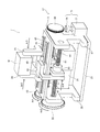
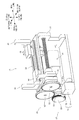
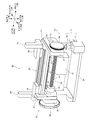
- FIGS. 2 to 5 are perspective views showing an example of the configuration of the hand.
- FIG. 4 is an explanatory view showing that the friction material can be attached to and detached from the outer periphery of the disc.
- FIG. 5 is an explanatory view showing that the pressing member is interchangeably connected to the moving device.
- the hand 7 includes a finger 23, 24, a base member 25, a support column member 27, 28, a linear guide 29, a motor 31, a power transmission mechanism 33, and a feed screw mechanism. It has 35, a brake device 37, and the like.
- the axial direction of the feed screw mechanism 35 is the "width direction”
- the extension directions of the fingers 23 and 24 are the “height direction”
- the directions perpendicular to the width direction and the height direction are the "depth”.
- the base member 25 is, for example, a substantially rectangular plate-shaped member.
- the surface 25a on the other side in the height direction of the base member 25, that is, the side opposite to the side on which the fingers 23, 24, etc. are arranged, is directly or other than the flange portion 21 of the arm 13 (not shown in FIGS. 2 and 3). It is indirectly fixed via the member of.
- the strut members 27 and 28 are erected on one side of the base member 25 in the height direction, that is, on the surface 25b opposite to the side fixed to the flange portion 21.
- the strut member 27 is arranged at one end of the base member 25 in the width direction, and the strut member 28 is arranged at the other end of the base member 25 in the width direction.
- the strut member 27 has a support portion 27a, a leg portion 27b, and a bearing portion 27c.
- the support portion 27a extends along the depth direction and is fixed to the surface 25b of the base member 25.
- the leg portion 27b is joined to a substantially central portion of the support portion 27a at a substantially right angle, and extends along the height direction.
- the bearing portion 27c is joined to the end portion of the leg portion 27b opposite to the support portion 27a at a substantially right angle, and extends along the depth direction.
- the bearing portion 27c is provided with bearings 39 that rotatably support the screw shafts 57 and 59, which will be described later, at two locations on one side and the other side in the depth direction.
- the strut member 28 has a support portion 28a, a leg portion 28b, and a bearing portion 28c.
- the support portion 28a extends along the depth direction and is fixed to the surface 25b of the base member 25.
- the leg portion 28b is joined to a substantially central portion of the support portion 28a at a substantially right angle, and extends along the height direction.
- the bearing portion 28c is joined to the end portion of the leg portion 28b opposite to the support portion 28a at a substantially right angle, and extends along the depth direction.
- the bearing portion 28c is provided with bearings 41 that rotatably support the screw shafts 57 and 59, which will be described later, at two locations on one side and the other side in the depth direction.
- the linear guide 29 (an example of a support member) is fixed to the base member 25 via two support support members 27 and 28, and movably supports the two fingers 23 and 24.
- the linear guide 29 has a base plate 43, two rails 45, 46, and two sliders 47, 48.
- the base plate 43 is, for example, a substantially rectangular plate-shaped member, and is bridged to the ends of the support columns 27 and 28 opposite to the base member 25.
- the two rails 45 and 46 extend along the width direction to the surface 43a on one side in the height direction of the base plate 43, and are arranged side by side in the depth direction so as to be substantially parallel to each other.
- the slider 47 is engaged with the rail 45 and moves along the rail 45.
- the slider 48 is engaged with the rail 46 and moves along the rail 46.
- the fingers 23 and 24 are connected to each of the two sliders 47 and 48 via connecting tools 49 and 50.
- the finger 23 connected to the slider 47 via the connector 49 is referred to as a first finger 23
- the finger 24 connected to the slider 48 via the connector 50 is also referred to as a second finger 24.
- the first finger 23 is a substantially L-shaped member in which the support portion 23a and the finger portion 23b are joined at a substantially right angle.
- the support portion 23a is connected to one end of the connector 49 in the width direction, and extends so as to project toward the rail 46 side along the depth direction.
- the finger portion 23b is joined to the end portion of the support portion 23a on the other side in the depth direction, and extends so as to project toward one side in the height direction.
- the length of the finger portion 23b is set to an appropriate length according to the size of the work W gripped by the hand 7.
- the second finger 24 is a substantially L-shaped member in which the support portion 24a and the finger portion 24b are joined at a substantially right angle.
- the support portion 24a is connected to the end portion on the other side in the width direction of the connector 50, and extends so as to project toward the rail 45 side along the depth direction.
- the finger portion 24b is joined to one end of the support portion 24a in the depth direction, and extends so as to project toward one side in the height direction.
- the length of the finger portion 24b is set to an appropriate length according to the size of the work W gripped by the hand 7.
- the first finger 23 and the second finger 24 move so as to be close to each other and are opened and closed.
- the slider 47 and the slider 48, and the connecting tool 49 and the connecting tool 50 are configured so as not to interfere with each other even when the first finger 23 and the second finger 24 approach each other.
- the positions of the finger portions 23b and 24b in the depth direction of the first finger 23 and the second finger 24 are substantially the same due to the overhang of the support portions 23a and 24a, and the first finger 23 and the second finger 24 are substantially the same.
- the fingers 23b and 24b are configured to come into contact with each other or face each other with a predetermined gap when the fingers are closed.
- the motor 31 opens and closes the first finger 23 and the second finger 24.
- the motor 31 is controlled by the controller 5 so that the control amount (rotation angle, rotation speed, torque, etc.) detected by the detector (not shown) follows the target value (command of position, speed, torque, etc.).
- It is a servo motor.
- a motor other than the servo motor may be used.
- the motor 31 is attached to the surface 25b of the base member 25 via an attachment member (not shown) so that the rotation axis direction is substantially parallel to the width direction between the column members 27 and 28.
- the motor 31 is arranged so that the load-side end of the housing is located in the vicinity of the support column member 28.
- the output shaft 31a of the motor 31 passes through a space S on one side in the height direction with respect to the support portion 28a of the strut member 28 and on one side in the depth direction with respect to the leg portion 28b, and is outside the strut member 28 (the other in the width direction). It is extended so as to protrude to the side).
- the power transmission mechanism 33 is arranged on the other side in the width direction of the support column member 28, and has a drive gear 51 and two driven gears 53 and 55.
- the drive gear 51 is coaxially connected to the other end of the output shaft 31a of the motor 31 in the width direction.
- the drive gear 51 meshes with the driven gear 53, and the driven gear 53 meshes with the driven gear 55.
- the driven gear 53 is connected so as to be coaxial with the other end of the screw shaft 57 in the width direction, and the driven gear 55 is connected so as to be coaxial with the other end of the screw shaft 59 in the width direction. Has been done.
- the driven gears 53 and 55 are rotatably supported together with the screw shafts 57 and 59 by the bearing 41 provided in the bearing portion 28c of the strut member 28.
- the driven gears 53 and 55 are formed so that the number of teeth and the diameter are equal to each other (gear ratio 1: 1), and the number of teeth and the diameter are larger than those of the drive gear 51.
- the gear ratios of the driven gears 53 and 55 are not limited to 1: 1 and the gear ratio may be changed as needed.
- the power transmission mechanism 33 is not limited to gears, and may be composed of, for example, a belt and a pulley, a chain and a sprocket, or the like. Although not shown, the power transmission mechanism 33 may be housed in a gear case.
- the feed screw mechanism 35 has two screw shafts 57 and 59 and two nuts 61 and 63.
- the screw shafts 57 and 59 are rotatably supported by bearings 39 and 41 provided on the column members 27 and 28.
- the screw shafts 57 and 59 extend along the width direction between the support columns 27 and 28, and are arranged side by side in the depth direction so as to be substantially parallel to each other. As a result, the screw shafts 57 and 59 are arranged so as to be in parallel with the linear guide 29 and the motor 31.
- the screw shaft 57 arranged on one side in the depth direction is also referred to as a first screw shaft 57
- the screw shaft 59 arranged on the other side in the depth direction is also referred to as a second screw shaft 59.
- the nuts 61 and 63 are connected to the screw shafts 57 and 59, respectively, and move in the axial direction as the screw shafts 57 and 59 rotate.
- the contact between the screw shafts 57 and 59 and the nuts 61 and 63 may be a feed screw mechanism which is a surface contact, or a ball screw mechanism which is a point contact via a ball (hard ball).
- the nut 61 that moves by the rotation of the first screw shaft 57 is also referred to as a first nut 61
- the nut 63 that moves by the rotation of the second screw shaft 59 is also referred to as a second nut 63.
- the first nut 61 is connected to the connecting tool 49 by a connecting member 65 (see FIG.
- the first finger 23 moves in the axial direction (width direction) as the first nut 61 moves.
- the second nut 63 is connected to the connector 50 by the connecting member 67, and the second finger 24 moves in the axial direction (width direction) as the second nut 63 moves.
- the brake device 37 is arranged on one side of the support column member 27 in the width direction, and has a disc 69 and a pressing device 71. That is, the brake device 37 is not a brake (electromagnetic brake or the like) built in the motor 31, but is configured as a separate body from the motor 31.
- the disk 69 (an example of a rotating body) is a disk-shaped member, and is connected to the end of the first screw shaft 57 (an example of a rotating shaft) rotated by the motor 31 so as to be coaxial with one end in the width direction. ing.
- the disc 69 is rotatably supported together with the first screw shaft 57 by the bearing 39 provided in the bearing portion 27c of the strut member 27.
- the diameter of the disc 69 is formed to be at least larger than the diameter of the first screw shaft 57, and is set to an appropriate value so that a desired braking force can be obtained.
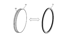
- a friction material 73 is replaceably installed on the outer circumference of the disc 69. As shown in FIG. 4, a groove 69a is formed on the outer periphery of the disc 69, and the friction material 73 is attached to and detached from the groove 69a.
- the friction material 73 may be made of, for example, a rubber material or a resin material.
- the friction material 73 by using, for example, an O-ring as the friction material 73, it can be easily mounted in the groove 69a without using an adhesive.
- the pressing device 71 is attached to one side of the support column member 27 in the width direction via an attachment member (not shown), and presses the friction material 73 provided on the outer circumference of the disc 69.
- the pressing device 71 includes a pressing member 75 that presses the outer circumference of the disc 69, and a moving device 77 that moves the pressing member 75 in the radial direction (in this example, the height direction) of the disc 69.
- the pressing device 71 may press the disc 69 to stop the rotation, and various actuators such as an air cylinder, an electric cylinder, a solenoid actuator, and a hydraulic cylinder can be used. In the present embodiment, air is used as the drive source of the brake device 37, and an air cylinder is used as the pressing device 71 to reduce the weight and cost of the hand 7.
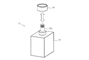
- the pressing member 75 is interchangeably connected to the moving device 77.
- a screw may be formed at the tip of the rod 77a of the moving device 77 and connected by screwing the pressing member 75.
- the pressing member 75 presses the outer circumference of the disc 69 to brake the disc 69 so that it does not rotate. As a result, the rotation of the screw shafts 57 and 59 is prohibited, and the positions of the fingers 23 and 24 are maintained. Therefore, when the brake device 37 is operated while the work W is being gripped by the motor 31 with a predetermined gripping force, the gripping force is maintained. As described above, by having the hand 7 in combination with the electrically driven motor 31 and the air-driven braking device 37, the weight is reduced while accurately controlling the gripping force and the braking force.
- the motor 31 and the brake device 37 are arranged on the side where the base member 25 is arranged (the other side in the height direction; an example of the first side) with respect to the linear guide 29.
- the fingers 23 and 24 are arranged on the side opposite to the side on which the base member 25 is arranged (one side in the height direction, an example of the second side) with respect to the linear guide 29.
- the width of the motor 31 and the feed screw mechanism 35 between the strut members 27 and 28, the brake device 37 on one side in the width direction of the strut member 27, and the width of the strut member 28.
- the power transmission mechanism 33 is arranged on the other side of the direction.
- FIG. 6 is a block diagram showing an example of the functional configuration of the controller 5.
- the controller 5 has a first control unit 79, a second control unit 81, a third control unit 83, and a fourth control unit 85.
- the controller 5 is composed of at least one of, for example, a servo amplifier, a motion controller, a personal computer (PC), a programmable logic controller (PLC), and the like.
- the first control unit 79 controls the motor 31 so that the work W is gripped by the fingers 23 and 24 with a predetermined gripping force. At this time, the first control unit 79 may perform torque control on the motor 31, for example, provide force sensors (not shown) on the fingers 23 and 24 and perform force control based on the detected values. May be good.
- the second control unit 81 operates the brake device 37 in a state where the work W is gripped with a predetermined gripping force so as to hold the respective positions of the fingers 23 and 24.
- the second control unit 81 controls a solenoid valve connected to an air source such as an air compressor, and supplies air to the pressing device 71.
- the moving device 77 moves the pressing member 75 to one side in the height direction to press the outer circumference of the disc 69, and brakes the disc 69 so that it does not rotate.
- the rotation of the screw shafts 57 and 59 is prohibited, and the positions of the fingers 23 and 24 are maintained.
- the gripping force when gripping the work W is maintained.
- the solenoid valve connected to the above air source is configured to maintain a state of supplying air to the pressing device 71 when the power supply is cut off due to a power failure or the like. As a result, even if the power supply to the hand 7 and the solenoid valve is cut off due to a power failure or the like while the hand 7 is gripping the work W, the brake device 37 continues to operate and grips the work W when it is gripped. You can maintain your strength. Therefore, it is possible to prevent the work W from falling.
- the third control unit 83 controls the motor 31 so that the torque generated by the motor 31 is smaller than that before the operation of the brake device 37 while the brake device 37 is operated. At this time, the torque generated by the motor 31 may be reduced to a predetermined target value, or for example, the power supply to the motor 31 may be cut off and the torque generated by the motor 31 may be set to 0 (so-called servo-off). As a result, power consumption during brake operation can be reduced. Even if the torque of the motor 31 is reduced in this way, the gripping force of the fingers 23 and 24 is maintained by the brake device 37 as described above.
- the fourth control unit 85 controls each of the motors M1 to M6 of the robot 3 so as to move the hand 7 to a desired position after reducing the torque generated by the motor (for example, after setting it to 0). As a result, the work W gripped by the hand 7 can be moved to a desired location.
- the processing and the like in the first control unit 79, the second control unit 81, the third control unit 83, the fourth control unit 85, and the like described above are not limited to the example of sharing these processes, for example. It may be processed by a smaller number of processing units (for example, one processing unit), or may be processed by a further subdivided processing unit. Further, the controller 5 may be implemented by an actual device only for a portion (inverter or the like) that supplies drive power to the motor, and other functions may be implemented by a program executed by the CPU 901 (see FIG. 13) described later. Part or all of it may be implemented by an actual device such as an ASIC, FPGA, or other electric circuit.
- FIG. 7 is a flowchart showing an example of the control contents executed by the controller 5 when the work W is conveyed.
- FIG. 8 is an explanatory view showing an example of the gripping operation of the hand 7
- FIG. 9 is an explanatory view showing an example of the operation when the brake device 37 is operating.
- step S10 the controller 5 controls the motors M1 to M6 of the robot 3 to move the hand 7 to the gripping position of the work W.
- step S20 the controller 5 controls the motor 31 by the first control unit 79, and grips the work W by the fingers 23 and 24 with a predetermined gripping force.
- the first control unit 79 may perform torque control on the motor 31 or may perform force control based on the detection value of the force sensor.
- FIG. 8 shows an example of the operation of the hand 7 at this time.
- the work W is gripped with the fingers 23 and 24 facing downward or in the horizontal direction, but in FIG. 8, the fingers 23 and 24 are turned upward in order to make it easier to understand the operation of each mechanism of the hand 7.
- the motor 31 rotates and the driven gears 53 and 55 rotate in the directions of the arrows Ar1 and Ar2, respectively, so that the first nut 61 coupled to the first screw shaft 57 moves in the direction of the arrow Ar3.
- the second nut 63 coupled to the second screw shaft 59 moves in the direction of the arrow Ar4.
- the first finger 23 and the second finger 24 move in the directions closer to each other (directions of arrows Ar5 and Ar6) and close, and the work W is gripped.
- step S30 the controller 5 operates the brake device 37 with the fingers 23 and 24 gripping the work W with a predetermined gripping force by the second control unit 81, and the fingers 23 and 24 are operated. Hold each position of.
- FIG. 9 shows an example of the operation of the brake device 37 at this time.
- the pressing device 71 moves the pressing member 75 toward the disc 69 side (direction of arrow Ar7) by the moving device 77, and presses the friction material 73 mounted on the outer circumference of the disc 69.
- the disc 69 is braked so as not to rotate, the rotation of the screw shafts 57 and 59 is prohibited, and the positions of the fingers 23 and 24 are maintained.
- the gripping force when gripping the work W is maintained.
- step S40 the controller 5 lowers the torque generated by the motor 31 in the state where the brake device 37 is operated by the third control unit 83 as compared with that before the operation of the brake device 37.
- the torque generated by the motor 31 may be reduced to a predetermined target value, or for example, the power supply to the motor 31 may be cut off and the torque generated by the motor 31 may be set to 0 (so-called servo-off).
- step S50 the controller 5 controls the motors M1 to M6 of the robot 3 by the fourth control unit 85, and moves the hand 7 to a desired position while holding the work W. Then, the controller 5 controls the motor 31 to open the fingers 23 and 24 at the moving destination of the hand 7, and places the work W in a predetermined place. This completes this flowchart.
- the robot system 1 of the present embodiment controls a hand 7 having two fingers 23 and 24 provided so as to be openable and closable, a robot 3 for moving the hand 7, and the robot 3 and the hand 7.
- the hand 7 has a motor 31 for opening and closing the fingers 23 and 24, and a brake device 37 for holding the respective positions of the fingers 23 and 24.
- the controller 5 has the fingers 23 and 24. 24 grips the work W with a predetermined gripping force so as to hold the positions of the first control unit 79 that controls the motor 31 and the fingers 23 and 24 so as to grip the work W with a predetermined gripping force.
- It has a second control unit 81 that operates the brake device 37 in this state.
- the work W is gripped by the fingers 23 and 24 with a predetermined gripping force, and the brake device 37 is operated in that state to hold the respective gripping positions of the fingers 23 and 24.
- the brake device 37 is operated in that state to hold the respective gripping positions of the fingers 23 and 24.
- the controller 5 controls the motor 31 so that the torque generated by the motor 31 is smaller than that before the operation of the brake device 37 when the brake device 37 is operated. Has 83.
- the motor 31 since the torque generated by the motor 31 after the operation of the brake device 37 is reduced, the motor 31 generates a torque for outputting a predetermined gripping force for a short time during which the brake device 37 can be operated. I hope I can. Therefore, the motor capacity can be reduced as compared with the case of using a motor capable of continuously generating the torque while gripping the work W. Therefore, the size and weight of the hand 7 can be reduced.
- the third control unit 83 controls the motor 31 so that the torque generated by the motor 31 becomes 0 while the brake device 37 is operated.
- the hand 7 which can reduce the power consumption while reducing the size and weight by reducing the capacity of the motor 31.
- the controller 5 has a fourth control unit 85 that controls the robot 3 so that the hand 7 is moved after the torque generated by the motor 31 is set to 0.
- the hand 7 can be moved while the gripping force is maintained by the brake device 37, so that the work W can be moved more safely.
- the brake device 37 is configured as a separate body from the motor 31.
- the motor 31 without a brake can be used for opening and closing the fingers 23 and 24.
- Motors with brakes generally use electromagnetic force, and tend to be heavier than motors without brakes. Therefore, the weight of the hand 7 can be reduced by using the motor 31 without a brake.
- the brake device 37 uses air as a drive source.
- an actuator driven by air is lighter and cheaper than an actuator driven by electricity. Therefore, it is possible to realize a hand 7 that can be reduced in weight at low cost.
- the brake device 37 is connected to the first screw shaft 57 rotated by the motor 31, and has a disc 69 having a diameter larger than that of the first screw shaft 57 and a pressing device that presses the disc 69. 71 and.
- the propulsive force is increased when the rotational motion of the first screw shaft 57 is converted into the opening / closing motion of the fingers 23 and 24, after the rotational motion of the first screw shaft 57 is converted into the opening / closing motion of the fingers 23 and 24.
- a large braking force may be required.
- the braking force is applied by pressing the disc 69 connected to the first screw shaft 57, the rotational movement of the first screw shaft 57 is before being converted into the opening / closing movement of the fingers 23 and 24.
- Braking force can be applied. As a result, it is possible to obtain a large braking force with a small pressing force, and the pressing device 71 can be made smaller and lighter.
- the diameter of the disc 69 since the magnitude of the brake torque is the product of the distance from the center of rotation of the first screw shaft 57 to the pressing point (outer circumference in this example) and the frictional force (pressing pressure x friction coefficient), the diameter of the disc 69.
- the braking force can be easily adjusted by changing the diameter of the disc 69, for example, the braking force obtained can be increased without increasing the size of the pressing device 71.
- the disc 69 which is a rotating body can be pressed at any angle position, the brake can be applied regardless of the gripping position of the fingers 23 and 24. Therefore, as long as it is within the stroke range of the hand 7, it is possible to realize the hand 7 capable of operating the brake regardless of the size of the work W.
- the brake device 37 has a friction material 73 that is replaceably installed on the outer periphery of the disc 69, and the pressing device 71 presses the friction material 73.
- the frictional force (pressing pressure x friction coefficient) between the pressing device 71 and the disc 69 can be increased, so that a larger braking torque can be obtained.
- the friction material 73 when the friction material 73 is worn, it can be easily replaced, so that maintainability can be improved.
- the friction material can be easily attached without using an adhesive.
- the pressing device 71 has a pressing member 75 that presses the outer circumference of the disc 69, and a moving device 77 that moves the pressing member 75 in the radial direction of the disc 69.
- the braking torque is the radius of the pressed portion x the frictional force (pressing pressure x friction coefficient).
- the outer circumference of the disc 69 which is the outermost radial direction, is pressed, a larger brake torque can be obtained.
- the width direction of the hand 7 is larger than that in the structure in which the pressing member 75 is moved in the axial direction (the axial direction of the first screw shaft 57). The size can be reduced and the hand 7 can be miniaturized.
- the pressing member 75 is interchangeably connected to the moving device 77.
- the magnitude of the frictional force between the pressing member 75 and the disc 69 is the product of the pressing force and the friction coefficient. Therefore, the pressing device 71 can be enlarged by replacing the pressing member 75 with a member having a larger friction coefficient (for example, a member having a coarser surface roughness or a member made of a material having a larger friction coefficient).
- the braking force obtained can be increased. In this way, the braking force can be easily adjusted by exchanging the pressing member 75. Further, when the pressing member 75 is worn, it can be easily replaced, so that maintainability can be improved.
- the disk 69 is arranged in parallel with the motor 31 and is connected to the first screw shaft 57 to which the rotational force of the motor 31 is transmitted.
- the first screw shaft 57 is arranged in parallel with the motor 31, it is possible to suppress an increase in the axial (width direction) dimension of the hand 7, and the hand 7 can be made compact. Further, since the length of the first screw shaft 57 can be secured, a large stroke of the hand 7 can be secured.
- the hand 7 has a first screw shaft 57 in which the first finger 23 and the second finger 24 and the first nut 61 to which the first finger 23 is connected are movably connected in the axial direction.
- a second screw shaft 59 which is arranged substantially parallel to the first screw shaft 57 and has a second nut 63 to which the second finger 24 is connected so as to be movable in the axial direction. 69 is connected to the first screw shaft 57.
- the screw shafts 57 and 59 are arranged in parallel as two configurations corresponding to the two fingers 23 and 24, respectively. Therefore, for example, in one screw shaft, the screw directions are opposite on one side and the other side. A larger stroke can be obtained as compared with the configuration in which the fingers 23 and 24 are opened and closed. Further, the stability of the brake can be improved by connecting the disc 69 to the first screw shaft 57 which is closer to the drive side (drive gear 51) by the motor 31 among the first screw shaft 57 and the second screw shaft 59.
- the hand 7 includes a base member 25 attached to the tip of the arm 13 of the robot 3 and a linear guide 29 fixed to the base member 25 and movably supporting the fingers 23 and 24.
- the motor 31 and the brake device 37 are arranged on the first side on which the base member 25 is arranged with respect to the linear guide 29, and the fingers 23 and 24 are arranged on the first side with respect to the linear guide 29. It is located on the second side, which is the opposite side of the side.
- the hand 7 can be miniaturized.
- Some motors can temporarily generate torque larger than the rated torque.
- a torque larger than the rated torque is generated to grip the work W, and the brake device 37 is operated in that state, a gripping force with a torque larger than the rated torque is maintained. You may try to do it.
- FIG. 10 is a flowchart showing an example of the control content executed by the controller 5A of this modified example when the work W is conveyed.
- step S110 the controller 5A controls the motors M1 to M6 of the robot 3 to move the hand 7 to the gripping position of the work W.
- step S120 the controller 5A controls the motor 31A so that the first control unit 79 generates a torque larger than the rated torque, and the fingers 23 and 24 grip the work W with a predetermined gripping force.
- step S130 the controller 5A operates the brake device 37 in a state where the fingers 23 and 24 grip the work W with a predetermined gripping force by the second control unit 81 to position each of the fingers 23 and 24. Hold.
- step S140 the controller 5A reduces the torque generated by the motor 31A to be equal to or less than the rated torque while the brake device 37 is operated by the third control unit 83.
- the torque generated by the motor 31A may be reduced to a predetermined target value, or for example, the power supply to the motor 31A may be cut off and the torque generated by the motor 31A may be set to 0 (so-called servo-off).
- step S150 the controller 5A controls the motors M1 to M6 of the robot 3 by the fourth control unit 85, and moves the hand 7 to a desired position while holding the work W. Then, the controller 5 controls the motors 31A to open the fingers 23 and 24 at the moving destination of the hand 7, and places the work W in a predetermined place. This completes this flowchart.
- a motor capable of generating a torque equal to or higher than the rated torque cannot continuously generate a torque larger than the rated torque, and a time limit is provided.
- a time limit is provided.
- the brake device 37 by operating the brake device 37 within the time limit, it is possible to continuously maintain the gripping force when gripping with a torque larger than the rated torque (for example, 150% of the rated torque). ..
- the motor capacity can be further reduced, and the hand 7 can be made smaller and lighter.
- the disc 69 is connected to the first screw shaft 57, but the disc 69 may be connected to the output shaft 31a of the motor 31.
- FIG. 11 is a perspective view showing an example of the configuration of the hand 7A of this modified example.
- the brake device 37 is arranged together with the power transmission mechanism 33 on the other side in the width direction of the support column member 28.
- the disc 69 is coaxially connected to the other end in the width direction (for example, the other end in the width direction of the drive gear 51) of the output shaft 31a (an example of the rotation shaft) of the motor 31.
- the pressing device 71 is attached to the other side of the support column member 28 in the width direction via an attachment member (not shown).
- the moving device 77 moves the pressing member 75 in the radial direction (in this example, the depth direction) of the disc 69. Since the configuration of the hand 7A other than the above is the same as that of the hand 7 according to the above-described embodiment, the description thereof will be omitted.
- the disc 69 can be directly connected to the output shaft 31a of the motor 31, so that the motor 31 can be connected to, for example, the first screw shaft 57 or the second screw shaft 59.
- the stability of the brake can be further improved as compared with the case of indirectly connecting to the output shaft 31a of the above. Further, since a space on one side of the support column member 27 in the width direction is freed up, another device such as a sensor can be installed in this space, and a more sophisticated hand can be realized.
- the disc 69 is connected to the first screw shaft 57, but it may be connected to the second screw shaft 59, which is the other screw shaft of the feed screw mechanism 35.
- FIG. 12 is a perspective view showing an example of the configuration of the hand 7B of this modified example.
- the disc 69 is coaxial with the end of the second screw shaft 59 (an example of the rotation shaft) on one side in the width direction. It is connected.
- the pressing device 71 is attached to the support column member 27 on one side in the width direction toward the other side in the depth direction via an attachment member (not shown).
- the moving device 77 moves the pressing member 75 in the radial direction (in this example, the height direction) of the disc 69. Since the configuration of the hand 7B other than the above is the same as that of the hand 7 according to the above-described embodiment, the description thereof will be omitted.
- the motor 31 is arranged closer to one side in the depth direction, whereas the brake device 37 can be arranged closer to the other side in the depth direction, so that the weight balance of the hand 7B can be improved.
- the feed screw mechanism 35 has two screw shafts 57 and 59.
- the fingers 23 and 24 are opened and closed with the screw directions opposite to each other on one side and the other side. May be good.
- the stroke of the hand is reduced, but the structure is simplified and the number of parts is reduced, so that further weight reduction, miniaturization, and cost reduction can be achieved.
- the pressing device 71 is configured to press the outer circumference of the disc 69 in the radial direction, but the pressing location and direction are not limited to this.
- the end face of the disc 69 may be pressed toward one side or the other side in the width direction.
- a hand having three or more fingers may be used, for example, a configuration in which three fingers move along a radial direction at intervals of 120 degrees.
- Controller hardware configuration example a hardware configuration example of the controller 5 that realizes processing by each of the control units 79, 81, 83, 85 and the like implemented by the program executed by the CPU 901 described above will be described. Note that, in FIG. 13, the configuration related to the function of supplying drive power to the motor of the controller 5 is appropriately omitted.
- the controller 5 includes, for example, a CPU 901, a ROM 903, a RAM 905, a dedicated integrated circuit 907 constructed for a specific application such as an ASIC or an FPGA, an input device 913, and an output device 915. It has a recording device 917, a drive 919, a connection port 921, and a communication device 923. These configurations are connected so that signals can be transmitted to each other via the bus 909 and the input / output interface 911.
- the program can be recorded in, for example, a recording device 917 or the like composed of a ROM 903, a RAM 905, a hard disk, or the like.
- the program is temporarily or non-temporarily (permanently) recorded on, for example, a magnetic disk such as a flexible disk, an optical disk such as various CDs, MO disks, or DVDs, or a removable recording medium 925 such as a semiconductor memory. You can also keep it.
- a recording medium 925 can also be provided as so-called package software.
- the program recorded on these recording media 925 may be read by the drive 919 and recorded on the recording device 917 via the input / output interface 911, the bus 909, or the like.
- the program can also be recorded on, for example, a download site, another computer, another recording device, etc. (not shown).
- the program is transferred via a network NW such as LAN or the Internet, and the communication device 923 receives this program.
- the program received by the communication device 923 may be recorded in the recording device 917 via the input / output interface 911, the bus 909, or the like.
- the program can be recorded in an appropriate externally connected device 927, for example.
- the program may be transferred via the appropriate connection port 921 and recorded in the recording device 917 via the input / output interface 911, the bus 909, or the like.
- the CPU 901 executes various processes according to the program recorded in the recording device 917, so that the first control unit 79, the second control unit 81, the third control unit 83, the fourth control unit 85, etc. Processing is realized.
- the CPU 901 may directly read the program from the recording device 917 and execute it, or may execute it after loading it into the RAM 905 once. Further, for example, when the CPU 901 receives the program via the communication device 923, the drive 919, or the connection port 921, the CPU 901 may directly execute the received program without recording it in the recording device 917.
- the CPU 901 may perform various processes based on signals and information input from an input device 913 such as a mouse, keyboard, microphone (not shown), if necessary.
- an input device 913 such as a mouse, keyboard, microphone (not shown), if necessary.
- the CPU 901 may output the result of executing the above processing from an output device 915 such as a display device or an audio output device, and the CPU 901 may connect the processing result to the communication device 923 or the communication device 923 as needed. It may be transmitted via the port 921, or may be recorded on the recording device 917 or the recording medium 925.
- an output device 915 such as a display device or an audio output device
- Robot system Robot 5 Controller 5A Controller 7 Hand 7A Hand 7B Hand 23 1st finger 24 2nd finger 25 Base member 29 Linear guide (support member) 31 Motor 31a Output shaft (rotary shaft) 31A Motor 37 Brake device 57 1st screw shaft (rotary shaft) 59 2nd screw shaft 61 1st nut 63 2nd nut 69 Disc (rotating body) 71 Pressing device 73 Friction material 75 Pressing member 77 Moving device 79 1st control unit 81 2nd control unit 83 3rd control unit 85 4th control unit W work
Landscapes
- Engineering & Computer Science (AREA)
- Robotics (AREA)
- Mechanical Engineering (AREA)
- Manipulator (AREA)
Abstract
【課題】ブレーキ装置を備えたハンドを軽量化する。 【解決手段】ロボットシステム1は、開閉可能に設けられた2つのフィンガ23,24を有するハンド7と、ハンド7を移動させるロボット3と、ロボット3及びハンド7を制御するコントローラ5と、を有し、ハンド7は、フィンガ23,24を開閉させるモータ31と、フィンガ23,24の各々の位置を保持するブレーキ装置37と、を有し、コントローラ5は、フィンガ23,24によりワークWを所定の把持力で把持するように、モータ31を制御する第1制御部79と、フィンガ23,24の各々の位置を保持するように、ワークWを所定の把持力で把持した状態でブレーキ装置37を作動させる第2制御部81と、を有する。
Description
開示の実施形態は、ロボットシステム、ハンド、ハンドの制御方法に関する。
特許文献1には、ハンド装置の把持装置への電源供給が遮断された場合に、把持装置が把持力を維持することができ、ワークを把持している場合にはワークを落下させることがない産業用ロボットのハンド装置が記載されている。
上記従来技術のハンド装置は、構造が複雑で部品点数が多いため、重量が大きくなるという課題がある。ハンド装置の重量はロボットの可搬重量に影響するため、ブレーキ装置を備えたハンド装置において更なる軽量化が要望されていた。
本発明はこのような問題点に鑑みてなされたものであり、ブレーキ装置を備えたハンドの軽量化が可能なロボットシステム、ハンド、ハンドの制御方法を提供することを目的とする。
上記課題を解決するため、本発明の一の観点によれば、開閉可能に設けられた複数のフィンガを有するハンドと、前記ハンドを移動させるロボットと、少なくとも前記ハンドを制御するコントローラと、を有し、前記ハンドは、前記複数のフィンガを開閉させるモータと、前記複数のフィンガの各々の位置を保持するブレーキ装置と、を有し、前記コントローラは、前記複数のフィンガによりワークを所定の把持力で把持するように、前記モータを制御する第1制御部と、前記複数のフィンガの各々の位置を保持するように、前記ワークを前記所定の把持力で把持した状態で前記ブレーキ装置を作動させる第2制御部と、を有するロボットシステムが適用される。
また、本発明の別の観点によれば、ワークを把持するハンドであって、開閉可能に設けられた複数のフィンガと、前記複数のフィンガを開閉させるモータと、前記複数のフィンガの各々の位置を保持するブレーキ装置と、を有し、前記ブレーキ装置は、前記モータにより回転される回転軸に連結され、前記回転軸よりも径が大きい回転体と、前記回転体を押圧する押圧装置と、を有するハンドが適用される。
また、本発明の別の観点によれば、開閉可能に設けられた複数のフィンガと、前記複数のフィンガを開閉させるモータと、前記複数のフィンガの各々の位置を保持するブレーキ装置と、を有するハンドの制御方法であって、前記複数のフィンガによりワークを所定の把持力で把持するように、前記モータを制御することと、前記複数のフィンガの各々の位置を保持するように、前記ワークを前記所定の把持力で把持した状態で前記ブレーキ装置を作動させることと、を有するハンドの制御方法が適用される。
本発明のロボットシステム等によれば、ブレーキ装置を備えたロボットハンドを軽量化することができる。
以下、一実施の形態について図面を参照しつつ説明する。
<1.ロボットシステム及びロボットの構成>
まず、図1を参照しつつ、実施形態に係るロボットシステム及びロボットの構成の一例について説明する。図1は、ロボットシステム及びロボットの構成の一例を概念的に表す概念図である。
まず、図1を参照しつつ、実施形態に係るロボットシステム及びロボットの構成の一例について説明する。図1は、ロボットシステム及びロボットの構成の一例を概念的に表す概念図である。
図1に示すように、ロボットシステム1は、ロボット3と、コントローラ5とを有する。
ロボット3は、例えば6つの関節部を備えた垂直多関節型の6軸ロボットであり、その先端には、エンドエフェクタとしてハンド7が取り付けられている。ロボット3は、ハンド7によりワークWを把持し、移動、載置、組み付け等の作業を行う。なお、ロボット3を6軸以外(例えば5軸や7軸等)のロボットとしてもよい。また、水平多関節型やパラレルリンクロボット等、ロボット3を垂直多関節型以外のロボットとしてもよい。さらに、汎用ロボット以外にも、例えば、XYZθ方向等に移動可能なアクチュエータを備えた専用作業機等としてもよい。
コントローラ5は、ロボット3及びハンド7の動作を制御する。コントローラ5は、ロボット3のボディ(例えば基台9)に取り付けられてもよいし、ロボット3と分離して別の場所に配置されてもよい。また、コントローラ5を、例えばロボット3を制御するコントローラとハンド7を制御するコントローラとに分けたり、例えば各種指令を出力する上位コントローラと、当該指令に基づいてロボット3やハンド7の各アクチュエータに駆動源(電力やエア)を供給するコントローラとに分ける等、複数の制御装置で構成してもよい。
図1に示すように、ロボット3は、基台9と、旋回部11と、アーム13と、ハンド7とを有する。基台9は、例えば床や壁、天井等に固定される。
旋回部11は、基台9の上端部に、上下方向に略平行な回転軸心Ax1まわりに旋回可能に支持されている。この旋回部11は、基台9との間の関節部に設けられたアクチュエータAc1の駆動により、基台9の上端部に対し、回転軸心Ax1まわりに旋回駆動される。
アーム13は、旋回部11の例えば一方側の側部に支持されている。このアーム13は、下腕部15と、上腕部17と、手首部19と、フランジ部21とを有する。
下腕部15は、旋回部11の一方側の側部に、回転軸心Ax1に略垂直な回転軸心Ax2まわりに旋回可能に支持されている。この下腕部15は、旋回部11との間の関節部に設けられたアクチュエータAc2の駆動により、旋回部11の一方側の側部に対し、回転軸心Ax2まわりに旋回駆動される。
上腕部17は、下腕部15の先端側に、回転軸心Ax2に略平行な回転軸心Ax3まわりに旋回可能且つ回転軸心Ax3に略垂直な回転軸心Ax4回りに回動可能に支持されている。この上腕部17は、下腕部15との間の関節部に設けられたアクチュエータAc3の駆動により、下腕部15の先端側に対し、回転軸心Ax3まわりに旋回駆動される。また上腕部17は、アクチュエータAc3との間に設けられたアクチュエータAc4の駆動により、下腕部15の先端側に対し、回転軸心Ax4まわりに回動駆動される。
手首部19は、上腕部17の先端側に、回転軸心Ax4に略垂直な回転軸心Ax5まわりに旋回可能に支持されている。この手首部19は、上腕部17との間の関節部に設けられたアクチュエータAc5の駆動により、上腕部17の先端側に対し、回転軸心Ax5まわりに旋回駆動される。
フランジ部21は、手首部19の先端側に、回転軸心Ax5に略垂直な回転軸心Ax6まわりに回動可能に支持されている。このフランジ部21は、手首部19との間の関節部に設けられたアクチュエータAc6の駆動により、手首部19の先端側に対し、回転軸心Ax6まわりに回動駆動される。
ハンド7は、フランジ部21の先端に取り付けられており、フランジ部21の回転軸心Ax6まわりの回動と共に、回転軸心Ax6まわりに回動する。このハンド7は、開閉可能に設けられた2つのフィンガ23,24を備えており、ワークWを把持することを初めとして、各種の操作や作業をすることが可能である。
以上の構成であるロボット3は、6つのアクチュエータAc1~Ac6を備えた6つの関節部を有する6軸ロボットである。各関節部を駆動するアクチュエータAc1~Ac6は、モータM1~M6、減速機(図示省略)及びブレーキ(図示省略)等により構成されている。なお、モータM1~M6、減速機及びブレーキ等は、必ずしも回転軸心Ax1~Ax6上に配置される必要はなく、これらの回転軸心Ax1~Ax6から離れた位置に配置されてもよい。
なお、上記では、アーム13の長手方向(あるいは延材方向)に沿った回転軸心まわりの回転を「回動」と呼び、アーム13の長手方向(あるいは延材方向)に略垂直な回転軸心まわりの回転を「旋回」と呼んで区別している。
<2.ハンドの構成>
次に、図2~図5を参照しつつ、ハンドの構成の一例について説明する。図2及び図3は、ハンドの構成の一例を表す斜視図である。図4は、ディスクの外周に摩擦材が着脱可能であることを表す説明図である。図5は、移動装置に押圧部材が交換可能に連結されることを表す説明図である。
次に、図2~図5を参照しつつ、ハンドの構成の一例について説明する。図2及び図3は、ハンドの構成の一例を表す斜視図である。図4は、ディスクの外周に摩擦材が着脱可能であることを表す説明図である。図5は、移動装置に押圧部材が交換可能に連結されることを表す説明図である。
図2及び図3に示すように、ハンド7は、フィンガ23,24と、ベース部材25と、支柱部材27,28と、リニアガイド29と、モータ31と、動力伝達機構33と、送りねじ機構35と、ブレーキ装置37等を有する。なお、以下では説明の便宜上、送りねじ機構35の軸方向を「幅方向」、フィンガ23,24の延設方向を「高さ方向」、これら幅方向と高さ方向に垂直な方向を「奥行き方向」、という。
ベース部材25は、例えば略長方形状の板状の部材である。ベース部材25の高さ方向他方側、すなわちフィンガ23,24等が配置される側とは反対側の表面25aは、アーム13のフランジ部21(図2及び図3では図示省略)に直接又は他の部材を介して間接的に固定されている。
支柱部材27,28は、ベース部材25の高さ方向一方側、すなわちフランジ部21に固定される側とは反対側の表面25bに立設されている。支柱部材27は、ベース部材25の幅方向一方側の端部に配置されており、支柱部材28は、ベース部材25の幅方向他方側の端部に配置されている。
支柱部材27は、支持部27aと、脚部27bと、軸受部27cとを有する。支持部27aは、奥行き方向に沿って延設され、ベース部材25の表面25bに固定されている。脚部27bは、支持部27aの略中央部分に略直角に接合されており、高さ方向に沿って延設されている。軸受部27cは、脚部27bの支持部27aとは反対側の端部に略直角に接合されており、奥行き方向に沿って延設されている。軸受部27cには、奥行き方向の一方側及び他方側の2箇所に、後述するねじ軸57,59を回転可能に支持する軸受39が設けられている。
同様に、支柱部材28は、支持部28aと、脚部28bと、軸受部28cとを有する。支持部28aは、奥行き方向に沿って延設され、ベース部材25の表面25bに固定されている。脚部28bは、支持部28aの略中央部分に略直角に接合されており、高さ方向に沿って延設されている。軸受部28cは、脚部28bの支持部28aとは反対側の端部に略直角に接合されており、奥行き方向に沿って延設されている。軸受部28cには、奥行き方向の一方側及び他方側の2箇所に、後述するねじ軸57,59を回転可能に支持する軸受41が設けられている。
リニアガイド29(支持部材の一例)は、ベース部材25に2つの支柱部材27,28を介して固定され、2つのフィンガ23,24を移動可能に支持する。リニアガイド29は、ベース板43と、2本のレール45,46と、2つのスライダ47,48とを有する。
ベース板43は、例えば略長方形状の板状の部材であり、支柱部材27,28のベース部材25とは反対側の端部に架け渡されている。2本のレール45,46は、ベース板43の高さ方向一方側の表面43aに幅方向に沿って延設されており、互いに略平行となるように奥行き方向に並んで配置されている。スライダ47はレール45に係合しており、レール45に沿って移動する。スライダ48はレール46に係合しており、レール46に沿って移動する。
フィンガ23,24は、2つのスライダ47,48の各々に、連結具49,50を介して連結されている。以下では説明の便宜上、スライダ47に連結具49を介して連結されたフィンガ23を第1フィンガ23、スライダ48に連結具50を介して連結されたフィンガ24を第2フィンガ24ともいう。
第1フィンガ23は、支持部23aと指部23bとが略直角に接合された、略L字状の部材である。支持部23aは、連結具49の幅方向一方側の端部に連結されており、奥行き方向に沿ってレール46側に向けて突出するように延設されている。指部23bは、支持部23aの奥行き方向他方側の端部に接合されており、高さ方向一方側に向けて突出するように延設されている。指部23bの長さは、ハンド7が把持するワークWのサイズに応じて適宜の長さに設定されている。
同様に、第2フィンガ24は、支持部24aと指部24bとが略直角に接合された、略L字状の部材である。支持部24aは、連結具50の幅方向他方側の端部に連結されており、奥行き方向に沿ってレール45側に向けて突出するように延設されている。指部24bは、支持部24aの奥行き方向一方側の端部に接合されており、高さ方向一方側に向けて突出するように延設されている。指部24bの長さは、ハンド7が把持するワークWのサイズに応じて適宜の長さに設定されている。
上記構成により、第1フィンガ23と第2フィンガ24とは、互いに遠近するように移動し開閉される。また、スライダ47とスライダ48、並びに、連結具49と連結具50は、第1フィンガ23と第2フィンガ24とが近づいても互いに干渉しないように構成されている。一方で、第1フィンガ23と第2フィンガ24とは、支持部23a,24aの張り出しにより、指部23b,24bの奥行き方向における位置が略一致しており、第1フィンガ23と第2フィンガ24とが閉じた際に、指部23b,24bが当接又は所定の間隙を空けて対峙するように構成されている。
モータ31は、第1フィンガ23と第2フィンガ24とを開閉させる。モータ31は、コントローラ5により、検出器(図示省略)で検出した制御量(回転角度、回転速度、トルク等)が目標値(位置、速度、トルク等の指令)に追従するように制御されるサーボモータである。但し、サーボモータ以外のモータを使用してもよい。モータ31は、支柱部材27,28の間において、回転軸方向が幅方向と略平行となるように、ベース部材25の表面25bに取付部材(図示省略)を介して取り付けられている。モータ31は、筐体の負荷側端部が支柱部材28の近傍に位置するように配置されている。モータ31の出力軸31aは、支柱部材28の支持部28aに対し高さ方向一方側、且つ、脚部28bに対し奥行方向一方側の空間Sを通って、支柱部材28の外側(幅方向他方側)に突出するように延設されている。
動力伝達機構33は、支柱部材28の幅方向他方側に配置されており、駆動ギア51と、2つの従動ギア53,55とを有する。駆動ギア51は、モータ31の出力軸31aの幅方向他方側の端部に同軸となるように連結されている。駆動ギア51は従動ギア53と噛み合っており、従動ギア53は従動ギア55と噛み合っている。従動ギア53は、ねじ軸57の幅方向他方側の端部に同軸となるように連結されており、従動ギア55は、ねじ軸59の幅方向他方側の端部に同軸となるように連結されている。これにより、従動ギア53,55は、支柱部材28の軸受部28cに設けられた軸受41によりねじ軸57,59と共に回転可能に支持されている。従動ギア53,55は、互いに歯数及び直径が等しくなるように形成されており(ギア比1:1)、駆動ギア51よりも歯数及び直径が大きくなるように形成されている。このように構成される動力伝達機構33により、モータ31の回転力(トルク)が増大されて2本のねじ軸57,59に伝達され、2本のねじ軸57,59は互いに反対の回転方向に同じ回転速度で回転する。
なお、従動ギア53,55のギア比は1:1に限定されるものではなく、必要に応じてギア比を変更してもよい。また、動力伝達機構33はギアに限定されるものではなく、例えばベルトとプーリ又はチェーンとスプロケット等で構成してもよい。また、図示は省略するが、動力伝達機構33はギアケースに収容されてもよい。
送りねじ機構35は、2本のねじ軸57,59と、2つのナット61,63とを有する。ねじ軸57,59は、支柱部材27,28に設けられた軸受39,41により回転可能に支持されている。ねじ軸57,59は、支柱部材27,28の間で幅方向に沿って延設されており、互いに略平行となるように奥行き方向に並んで配置されている。その結果、ねじ軸57,59は、リニアガイド29やモータ31とも並列となるように配置されている。以下では説明の便宜上、奥行き方向一方側に配置されたねじ軸57を第1ねじ軸57、奥行き方向他方側に配置されたねじ軸59を第2ねじ軸59ともいう。
ナット61,63は、ねじ軸57,59の各々に結合しており、ねじ軸57,59の回転に伴って軸方向に移動する。なお、ねじ軸57,59とナット61,63との接触が面接触である送りねじ機構としてもよいし、ボール(硬球)を介した点接触であるボールねじ機構としてもよい。以下では説明の便宜上、第1ねじ軸57の回転により移動するナット61を第1ナット61、第2ねじ軸59の回転により移動するナット63を第2ナット63ともいう。第1ナット61は、連結部材65(図3参照)により連結具49に連結されており、第1ナット61の移動に伴って第1フィンガ23が軸方向(幅方向)に移動する。同様に、第2ナット63は、連結部材67により連結具50に連結されており、第2ナット63の移動に伴って第2フィンガ24が軸方向(幅方向)に移動する。
ブレーキ装置37は、支柱部材27の幅方向一方側に配置されており、ディスク69と、押圧装置71とを有する。すなわち、ブレーキ装置37は、モータ31に内蔵されたブレーキ(電磁ブレーキ等)ではなく、モータ31とは別体として構成されている。ディスク69(回転体の一例)は、円盤状の部材であり、モータ31により回転される第1ねじ軸57(回転軸の一例)の幅方向一方側の端部に同軸となるように連結されている。これにより、ディスク69は、支柱部材27の軸受部27cに設けられた軸受39により第1ねじ軸57と共に回転可能に支持されている。ディスク69の直径は、少なくとも第1ねじ軸57の直径よりも大きく形成されており、所望のブレーキ力が得られるように適宜の値に設定されている。
ディスク69の外周には、摩擦材73が交換可能に設置されている。図4に示すように、ディスク69の外周には溝69aが形成されており、摩擦材73は当該溝69aに対して着脱される。摩擦材73は、摩擦係数が大きな材質とすることで、大きなブレーキ力を得ることができる。また摩擦材73は、柔軟性を有する材質とすることで、ディスク69の溝69aへの着脱が容易となる。したがって、摩擦材73を例えばゴム材や樹脂材料等で構成してもよい。本実施形態では、摩擦材73として例えばOリングを使用することで、接着剤を使用せずに簡単に溝69aに装着することができる。
押圧装置71は、支柱部材27の幅方向一方側に取付部材(図示省略)を介して取り付けられており、ディスク69の外周に設けられた摩擦材73を押圧する。押圧装置71は、ディスク69の外周を押圧する押圧部材75と、押圧部材75をディスク69の径方向(この例では高さ方向)に移動させる移動装置77とを有する。押圧装置71は、ディスク69を押圧して回転を静止できればよく、例えばエアシリンダ、電動シリンダ、ソレノイドアクチュエータ、油圧シリンダ等の様々なアクチュエータを使用することができる。本実施形態では、ブレーキ装置37の駆動源にエアを採用し、押圧装置71としてエアシリンダを用いることで、ハンド7の軽量化及び低コスト化を図っている。
押圧部材75は、移動装置77に対して交換可能に連結されている。例えば図5に示すように、移動装置77のロッド77aの先端にねじを形成しておき、押圧部材75をねじ込むことにより連結する構成としてもよい。なお、ねじ締結以外の手法(例えば嵌合やジョイント等)で連結してもよい。押圧部材75が交換可能であるため、押圧部材75を例えば面粗度や材質等が異なる別の種類のものに変更することで、押圧部材75とディスク69(摩擦材73)との間の摩擦力(押圧力×摩擦係数)を変更することができる。また、押圧部材75が摩耗した場合には容易に交換できるので、メンテナンス性を向上できる。
ブレーキ装置37が作動すると、押圧部材75がディスク69の外周を押圧してディスク69が回転しないように制動する。これにより、ねじ軸57,59の回転が禁止され、フィンガ23,24の各々の位置が保持される。したがって、モータ31により所定の把持力でワークWを把持している状態でブレーキ装置37を作動させた場合には、把持力が維持される。このように、ハンド7は、電気駆動のモータ31とエア駆動のブレーキ装置37とを組み合わせて有することで、把持力及びブレーキ力を精度良く制御しつつ、軽量化を図っている。
以上のように構成されるハンド7では、モータ31及びブレーキ装置37は、リニアガイド29に対しベース部材25が配置される側(高さ方向他方側。第1のサイドの一例)に配置されており、フィンガ23,24は、リニアガイド29に対しベース部材25が配置される側とは反対側(高さ方向一方側。第2のサイドの一例)に配置されている。さらに、リニアガイド29のベース部材25が配置される側では、支柱部材27,28の間にモータ31と送りねじ機構35、支柱部材27の幅方向一方側にブレーキ装置37、支柱部材28の幅方向他方側に動力伝達機構33が配置されている。このような配置により、ベース部材25とリニアガイド29との間のスペースを有効活用すると共に、機器配置を最適化することができる。したがって、ハンド7を小型化できる。
<3.コントローラの機能構成>
次に、図6を参照しつつ、コントローラ5の機能構成の一例について説明する。図6は、コントローラ5の機能構成の一例を表すブロック図である。
次に、図6を参照しつつ、コントローラ5の機能構成の一例について説明する。図6は、コントローラ5の機能構成の一例を表すブロック図である。
図6に示すように、コントローラ5は、第1制御部79と、第2制御部81と、第3制御部83と、第4制御部85とを有する。コントローラ5は、例えばサーボアンプ、モーションコントローラ、パーソナルコンピュータ(PC)、プログラマブルロジックコントローラ(PLC)等のうちの少なくとも1つにより構成される。
第1制御部79は、フィンガ23,24によりワークWを所定の把持力で把持するようにモータ31を制御する。このとき、第1制御部79はモータ31に対してトルク制御を行ってもよいし、例えばフィンガ23,24に力センサ(図示省略)を設けておき、その検出値に基づく力制御を行なってもよい。
第2制御部81は、フィンガ23,24の各々の位置を保持するように、ワークWを所定の把持力で把持した状態でブレーキ装置37を作動させる。具体的には、第2制御部81は、例えばエアコンプレッサ等のエア源に接続された電磁弁を制御し、押圧装置71にエアを供給する。これにより、移動装置77が押圧部材75を高さ方向一方側に移動させてディスク69の外周を押圧し、ディスク69が回転しないように制動する。これにより、ねじ軸57,59の回転が禁止され、フィンガ23,24の各々の位置が保持される。その結果、ワークWを把持した際の把持力が維持される。
なお、上記のエア源に接続された電磁弁は、停電等により電源供給が遮断された場合には、押圧装置71にエアを供給する状態を維持するように構成されている。これにより、ハンド7がワークWを把持した状態で停電等によりハンド7や電磁弁等への電源供給が遮断された場合でも、ブレーキ装置37は作動を継続し、ワークWを把持した際の把持力を維持することができる。したがって、ワークWの落下を防止することができる。
第3制御部83は、ブレーキ装置37を作動させた状態で、モータ31が発生するトルクをブレーキ装置37の作動前よりも小さくするように、モータ31を制御する。このとき、モータ31が発生するトルクを所定の目標値まで低下させてもよいし、例えばモータ31への電力供給を遮断してモータ31が発生するトルクを0としてもよい(いわゆるサーボオフ)。これにより、ブレーキ作動中の消費電力を削減できる。なお、このようにモータ31のトルクを低減させても、上述のようにブレーキ装置37によりフィンガ23,24による把持力は維持される。
第4制御部85は、モータが発生するトルクを低減した後に(例えば0とした後に)、ハンド7を所望の位置に移動させるように、ロボット3の各モータM1~M6を制御する。これにより、ハンド7で把持したワークWを所望の場所へ移動させることができる。
なお、上述した第1制御部79、第2制御部81、第3制御部83、第4制御部85等における処理等は、これらの処理の分担の例に限定されるものではなく、例えば、更に少ない数の処理部(例えば1つの処理部)で処理されてもよく、また、更に細分化された処理部により処理されてもよい。また、コントローラ5は、モータに駆動電力を給電する部分(インバータ等)のみ実際の装置により実装され、その他の機能は後述するCPU901(図13参照)が実行するプログラムにより実装されてもよいし、その一部又は全部がASICやFPGA、その他の電気回路等の実際の装置により実装されてもよい。
<4.コントローラの制御内容及びハンドの動作>
次に、図7~図9を参照しつつ、ワークWの搬送時にコントローラ5が実行する制御内容の一例及びハンド7等の動作の一例について説明する。図7は、ワークWの搬送時にコントローラ5が実行する制御内容の一例を表すフローチャートである。図8は、ハンド7の把持動作の一例を表す説明図であり、図9は、ブレーキ装置37の作動時の動作の一例を表す説明図である。
次に、図7~図9を参照しつつ、ワークWの搬送時にコントローラ5が実行する制御内容の一例及びハンド7等の動作の一例について説明する。図7は、ワークWの搬送時にコントローラ5が実行する制御内容の一例を表すフローチャートである。図8は、ハンド7の把持動作の一例を表す説明図であり、図9は、ブレーキ装置37の作動時の動作の一例を表す説明図である。
図7に示すように、ステップS10では、コントローラ5は、ロボット3の各モータM1~M6を制御して、ハンド7をワークWの把持位置に移動させる。
ステップS20では、コントローラ5は、第1制御部79によりモータ31を制御して、フィンガ23,24によりワークWを所定の把持力で把持する。このとき、第1制御部79はモータ31に対してトルク制御を行ってもよいし、力センサの検出値に基づく力制御を行なってもよい。
図8に、このときのハンド7の動作の一例を示す。なお、通常はフィンガ23,24を下方又は水平方向等に向けてワークWを把持するが、図8ではハンド7の各機構の動作を分かり易くするためにフィンガ23,24を上方に向けた状態で図示している。図8に示すように、モータ31が回転して従動ギア53,55がそれぞれ矢印Ar1,Ar2の方向に回転することにより、第1ねじ軸57に結合した第1ナット61が矢印Ar3方向に移動すると共に、第2ねじ軸59に結合した第2ナット63が矢印Ar4方向に移動する。これにより、第1フィンガ23と第2フィンガ24とが互いに近づく方向(矢印Ar5,Ar6方向)に移動して閉じ、ワークWを把持する。
図7に戻り、ステップS30では、コントローラ5は、第2制御部81により、フィンガ23,24がワークWを所定の把持力で把持した状態で、ブレーキ装置37を作動させて、フィンガ23,24の各々の位置を保持する。
図9に、このときのブレーキ装置37の動作の一例を示す。図9に示すように、押圧装置71は、移動装置77により押圧部材75をディスク69側(矢印Ar7方向)に移動させて、ディスク69の外周に装着された摩擦材73を押圧する。これにより、ディスク69が回転しないように制動されると共に、ねじ軸57,59の回転が禁止され、フィンガ23,24の各々の位置が保持される。その結果、ワークWを把持した際の把持力が維持される。
図7に戻り、ステップS40では、コントローラ5は、第3制御部83により、ブレーキ装置37を作動させた状態で、モータ31が発生するトルクをブレーキ装置37の作動前よりも低下させる。このとき、モータ31が発生するトルクを所定の目標値まで低下させてもよいし、例えばモータ31への電力供給を遮断してモータ31が発生するトルクを0としてもよい(いわゆるサーボオフ)。
ステップS50では、コントローラ5は、第4制御部85により、ロボット3の各モータM1~M6を制御して、ワークWを把持した状態で、ハンド7を所望の位置に移動させる。そして、コントローラ5は、ハンド7の移動先において、モータ31を制御してフィンガ23,24を開き、ワークWを所定の場所に載置する。以上により、本フローチャートを終了する。
<5.実施形態の効果>
以上説明したように、本実施形態のロボットシステム1は、開閉可能に設けられた2つのフィンガ23,24を有するハンド7と、ハンド7を移動させるロボット3と、ロボット3及びハンド7を制御するコントローラ5と、を有し、ハンド7は、フィンガ23,24を開閉させるモータ31と、フィンガ23,24の各々の位置を保持するブレーキ装置37と、を有し、コントローラ5は、フィンガ23,24によりワークWを所定の把持力で把持するように、モータ31を制御する第1制御部79と、フィンガ23,24の各々の位置を保持するように、ワークWを所定の把持力で把持した状態でブレーキ装置37を作動させる第2制御部81と、を有する。
以上説明したように、本実施形態のロボットシステム1は、開閉可能に設けられた2つのフィンガ23,24を有するハンド7と、ハンド7を移動させるロボット3と、ロボット3及びハンド7を制御するコントローラ5と、を有し、ハンド7は、フィンガ23,24を開閉させるモータ31と、フィンガ23,24の各々の位置を保持するブレーキ装置37と、を有し、コントローラ5は、フィンガ23,24によりワークWを所定の把持力で把持するように、モータ31を制御する第1制御部79と、フィンガ23,24の各々の位置を保持するように、ワークWを所定の把持力で把持した状態でブレーキ装置37を作動させる第2制御部81と、を有する。
本実施形態のハンド7は、フィンガ23,24でワークWを所定の把持力で把持し、その状態でブレーキ装置37を作動させてフィンガ23,24の各々の把持位置を保持する。これにより、ワークWを把持した状態で例えば停電や非常停止、アラーム発生等によりハンド7等への電源供給が遮断された場合でも、ワークWを把持した際の把持力を維持することが可能となり、ワークWの落下を防止することができる。また、ブレーキ装置37によりフィンガ23,24の把持位置を保持することによって把持力を維持するので、モータ31は所定の把持力を出力するためのトルクをワークWの把持中に継続的に発生する必要がない。これにより、当該トルクをワークWの把持中に継続的に発生することが可能なモータを使用する場合に比べて、モータ容量を小さくすることが可能になる。したがって、ハンド7の小型化、軽量化を図ることができる。
また、本実施形態では特に、コントローラ5は、ブレーキ装置37を作動させた状態で、モータ31が発生するトルクをブレーキ装置37の作動前よりも小さくするようにモータ31を制御する第3制御部83を有する。
本実施形態では、ブレーキ装置37の作動後にモータ31が発生するトルクを小さくするので、モータ31はブレーキ装置37を作動させることが可能な短い時間だけ所定の把持力を出力するためのトルクを発生できればよい。したがって、当該トルクをワークWの把持中に継続的に発生することが可能なモータを使用する場合に比べて、モータ容量を小さくすることができる。したがって、ハンド7の小型化、軽量化を図ることができる。
また、本実施形態では特に、第3制御部83は、ブレーキ装置37を作動させた状態で、モータ31が発生するトルクを0とするようにモータ31を制御する。これにより、モータ31の小容量化により小型化、軽量化を図りつつ、消費電力を削減できるハンド7を実現できる。
また、本実施形態では特に、コントローラ5は、モータ31が発生するトルクを0とした後にハンド7を移動させるように、ロボット3を制御する第4制御部85を有する。これにより、ブレーキ装置37により把持力を維持した状態でハンド7を移動できるので、ワークWをより安全に移動させることができる。
また、本実施形態では特に、ブレーキ装置37は、モータ31とは別体として構成されている。これにより、フィンガ23,24の開閉にブレーキ付きでないモータ31を使用することができる。ブレーキ付きのモータは電磁力を利用したものが一般的であり、ブレーキ付きでないモータに比べて重量が大きくなりやすい。したがって、ブレーキ付きでないモータ31を使用できることで、ハンド7を軽量化できる。
また、本実施形態では特に、ブレーキ装置37は、エアを駆動源とする。一般にエアを駆動源とするアクチュエータは電気を駆動源とするアクチュエータよりも軽量で低コストである。したがって、低コストで軽量化が可能なハンド7を実現できる。
また、本実施形態では特に、ブレーキ装置37は、モータ31により回転される第1ねじ軸57に連結され、当該第1ねじ軸57よりも径が大きいディスク69と、ディスク69を押圧する押圧装置71と、を有する。
第1ねじ軸57の回転運動がフィンガ23,24の開閉運動に変換されると推進力が増大されるため、第1ねじ軸57の回転運動がフィンガ23,24の開閉運動に変換された後にブレーキ力を作用させる場合、大きなブレーキ力が必要となる場合がある。本実施形態では、第1ねじ軸57に連結されたディスク69を押圧することでブレーキ力を作用させるため、第1ねじ軸57の回転運動がフィンガ23,24の開閉運動に変換される前にブレーキ力を作用させることができる。これにより、小さな押圧力で大きなブレーキ力を得ることが可能となり、押圧装置71を小型化、軽量化できる。また、ブレーキトルクの大きさは、第1ねじ軸57の回転中心から押圧箇所(この例では外周)までの距離と摩擦力(押圧力×摩擦係数)の積となることから、ディスク69の径を大きくすることで、押圧装置71を大型化することなく得られるブレーキ力を大きくすることができる等、ディスク69の径の変更によりブレーキ力を容易に調整することができる。さらに、回転体であるディスク69はどの角度位置にあっても押圧することが可能であるため、フィンガ23,24がどのような把持位置であってもブレーキをかけることができる。したがって、ハンド7のストロークの範囲内であれば、ワークWの大小を問わずにブレーキを作動させることが可能なハンド7を実現できる。
また、本実施形態では特に、ブレーキ装置37は、ディスク69の外周に交換可能に設置された摩擦材73を有し、押圧装置71は、摩擦材73を押圧する。
これにより、押圧装置71とディスク69との間の摩擦力(押圧力×摩擦係数)を増大できるので、より大きなブレーキトルクを得ることができる。また、摩擦材73が摩耗した場合には容易に交換できるので、メンテナンス性を向上できる。さらに、ディスク69の外周に溝69aを設けておき、摩擦材73としてOリングを使用することにより、接着剤を使用せずに簡単に摩擦材を取り付けることが可能となる。
また、本実施形態では特に、押圧装置71は、ディスク69の外周を押圧する押圧部材75と、押圧部材75をディスク69の径方向に移動させる移動装置77と、を有する。
ディスク69を押圧してブレーキ力を作用させる場合、ブレーキトルクは押圧箇所の半径×摩擦力(押圧力×摩擦係数)となる。本実施形態では、ディスク69の最も径方向外側である外周を押圧するので、より大きなブレーキトルクを得ることができる。また、押圧部材75をディスク69の径方向に移動させる構造とすることにより、押圧部材75を軸方向(第1ねじ軸57の軸方向)に移動させる構造に比べて、ハンド7の幅方向の寸法を小さくでき、ハンド7を小型化できる。
また、本実施形態では特に、押圧部材75は、移動装置77に対して交換可能に連結されている。
押圧部材75とディスク69との間の摩擦力の大きさは、押圧力と摩擦係数との積となる。したがって、押圧部材75をより摩擦係数の大きいもの(例えば面粗度がより粗い部材や、摩擦係数がより大きな材質で構成された部材等)に交換することで、押圧装置71を大型化することなく、得られるブレーキ力を大きくすることができる。このように、押圧部材75を交換することでブレーキ力を容易に調整することができる。また、押圧部材75が摩耗した場合には容易に交換できるので、メンテナンス性を向上できる。
また、本実施形態では特に、ディスク69は、モータ31と並列に配置され、モータ31の回転力が伝達される第1ねじ軸57に連結されている。
本実施形態では、第1ねじ軸57をモータ31と並列に配置するので、ハンド7の軸方向(幅方向)の寸法が増大するのを抑制でき、ハンド7をコンパクト化できる。また、第1ねじ軸57の長さを確保できるので、ハンド7のストロークを大きく確保できる。
また、本実施形態では特に、ハンド7は、第1フィンガ23及び第2フィンガ24と、第1フィンガ23が連結された第1ナット61が軸方向に移動可能に結合された第1ねじ軸57と、第1ねじ軸57と略平行に配置され、第2フィンガ24が結合された第2ナット63が軸方向に移動可能に連結された第2ねじ軸59と、を有しており、ディスク69は、第1ねじ軸57に連結されている。
本実施形態では、ねじ軸57,59を2つのフィンガ23,24にそれぞれ対応させた2本構成として平行に配置するので、例えば1本のねじ軸において一方側と他方側でねじ方向を反対としてフィンガ23,24を開閉させる構成に比べて、より大きなストロークを得ることができる。また、第1ねじ軸57と第2ねじ軸59のうち、モータ31による駆動側(駆動ギア51)により近い第1ねじ軸57にディスク69を連結させることで、ブレーキの安定性を向上できる。
また、本実施形態では特に、ハンド7は、ロボット3のアーム13の先端に取り付けられるベース部材25と、ベース部材25に固定され、フィンガ23,24を移動可能に支持するリニアガイド29と、を有し、モータ31及びブレーキ装置37は、リニアガイド29に対しベース部材25が配置される側である第1のサイドに配置されており、フィンガ23,24は、リニアガイド29に対し第1のサイドとは反対側である第2のサイドに配置されている。
これにより、ベース部材25とリニアガイド29との間のスペースを有効活用して機器配置を最適化することができる。したがって、ハンド7を小型化できる。
<6.変形例>
なお、開示の実施形態は、上記に限られるものではなく、その趣旨及び技術的思想を逸脱しない範囲内で種々の変形が可能である。以下、そのような変形例について説明する。
なお、開示の実施形態は、上記に限られるものではなく、その趣旨及び技術的思想を逸脱しない範囲内で種々の変形が可能である。以下、そのような変形例について説明する。
(6-1.定格トルクよりも大きなトルクを発生させる場合)
モータには、定格トルクよりも大きなトルクを一時的に発生させることが可能なものがある。このようなモータ31Aをハンド7に使用して、定格トルクより大きなトルクを発生させてワークWを把持し、その状態でブレーキ装置37を作動させることにより、定格トルクより大きなトルクによる把持力を維持するようにしてもよい。
モータには、定格トルクよりも大きなトルクを一時的に発生させることが可能なものがある。このようなモータ31Aをハンド7に使用して、定格トルクより大きなトルクを発生させてワークWを把持し、その状態でブレーキ装置37を作動させることにより、定格トルクより大きなトルクによる把持力を維持するようにしてもよい。
図10は、ワークWの搬送時に本変形例のコントローラ5Aが実行する制御内容の一例を表すフローチャートである。
図10に示すように、ステップS110では、コントローラ5Aは、ロボット3の各モータM1~M6を制御して、ハンド7をワークWの把持位置に移動させる。
ステップS120では、コントローラ5Aは、第1制御部79により、定格トルクよりも大きいトルクを発生するようにモータ31Aを制御して、フィンガ23,24によりワークWを所定の把持力で把持する。
ステップS130では、コントローラ5Aは、第2制御部81により、フィンガ23,24がワークWを所定の把持力で把持した状態で、ブレーキ装置37を作動させて、フィンガ23,24の各々の位置を保持する。
ステップS140では、コントローラ5Aは、第3制御部83により、ブレーキ装置37を作動させた状態で、モータ31Aが発生するトルクを定格トルク以下となるように低下させる。このとき、モータ31Aが発生するトルクを所定の目標値まで低下させてもよいし、例えばモータ31Aへの電力供給を遮断してモータ31Aが発生するトルクを0としてもよい(いわゆるサーボオフ)。
ステップS150では、コントローラ5Aは、第4制御部85により、ロボット3の各モータM1~M6を制御して、ワークWを把持した状態で、ハンド7を所望の位置に移動させる。そして、コントローラ5は、ハンド7の移動先において、モータ31Aを制御してフィンガ23,24を開き、ワークWを所定の場所に載置する。以上により、本フローチャートを終了する。
本変形例によれば、次のような効果を得る。すなわち、一般に、定格トルク以上のトルクを発生可能なモータは、定格トルクよりも大きなトルクを継続的に発生することはできず、時間制限が設けられている。本変形例では、その時間制限内にブレーキ装置37を作動させることにより、定格トルクより大きなトルク(例えば定格トルクの150%)で把持した際の把持力を継続的に維持することが可能となる。これにより、モータ容量をさらに小さくでき、ハンド7の小型化、軽量化を図ることができる。
(6-2.ディスクをモータの出力軸に連結させる場合)
上記実施形態では、ディスク69を第1ねじ軸57に連結する構成としたが、ディスク69をモータ31の出力軸31aに連結してもよい。
上記実施形態では、ディスク69を第1ねじ軸57に連結する構成としたが、ディスク69をモータ31の出力軸31aに連結してもよい。
図11は、本変形例のハンド7Aの構成の一例を表す斜視図である。図11に示すように、ハンド7Aでは、支柱部材28の幅方向他方側に、動力伝達機構33と共にブレーキ装置37が配置されている。ディスク69は、モータ31の出力軸31a(回転軸の一例)の幅方向他方側の端部(例えば駆動ギア51のさらに幅方向他方側の端部)に同軸となるように連結されている。押圧装置71は、支柱部材28の幅方向他方側に取付部材(図示省略)を介して取り付けられている。移動装置77は、押圧部材75をディスク69の径方向(この例では奥行き方向)に移動させる。なお、ハンド7Aの上記以外の構成は、前述の実施形態に係るハンド7と同様であるため説明を省略する。
本変形例によれば、ディスク69をモータ31の出力軸31aに直接連結することができるので、例えばディスク69を第1ねじ軸57や第2ねじ軸59に連結する場合のように、モータ31の出力軸31aに対して間接的に連結する場合に比べて、ブレーキの安定性をさらに向上できる。また、支柱部材27の幅方向一方側のスペースが空くので、このスペースに例えばセンサ等の別の機器を設置することが可能となり、さらに高機能なハンドを実現できる。
(6-3.ディスクを第2ねじ軸に連結させる場合)
上記実施形態では、ディスク69を第1ねじ軸57に連結する構成としたが、送りねじ機構35のもう一方のねじ軸である第2ねじ軸59に連結してもよい。
上記実施形態では、ディスク69を第1ねじ軸57に連結する構成としたが、送りねじ機構35のもう一方のねじ軸である第2ねじ軸59に連結してもよい。
図12は、本変形例のハンド7Bの構成の一例を表す斜視図である。図12に示すように、ハンド7Bでは、支柱部材27の幅方向一方側において、ディスク69は、第2ねじ軸59(回転軸の一例)の幅方向一方側の端部に同軸となるように連結されている。これに対応して、押圧装置71は、支柱部材27の幅方向一方側における奥行き方向他方側寄りに、取付部材(図示省略)を介して取り付けられている。移動装置77は、押圧部材75をディスク69の径方向(この例では高さ方向)に移動させる。なお、ハンド7Bの上記以外の構成は、前述の実施形態に係るハンド7と同様であるため説明を省略する。
本変形例のハンド7Bによれば、モータ31が奥行き方向一方側寄りに配置されるのに対して、ブレーキ装置37を奥行き方向他方側寄りに配置できるので、ハンド7Bの重量バランスを向上できる。
(6-4.その他)
以上では、送りねじ機構35が2本のねじ軸57,59を有する構成としたが、例えば1本のねじ軸において一方側と他方側でねじ方向を反対としてフィンガ23,24を開閉させる構成としてもよい。この場合には、ハンドのストロークは小さくなるが、構造が簡素となり部品点数も少なくなるので、さらなる軽量化、小型化及び低コスト化を図ることができる。
以上では、送りねじ機構35が2本のねじ軸57,59を有する構成としたが、例えば1本のねじ軸において一方側と他方側でねじ方向を反対としてフィンガ23,24を開閉させる構成としてもよい。この場合には、ハンドのストロークは小さくなるが、構造が簡素となり部品点数も少なくなるので、さらなる軽量化、小型化及び低コスト化を図ることができる。
また以上では、押圧装置71でディスク69の外周を径方向に押圧する構成としたが、押圧箇所や方向はこれに限定されるものではない。例えば、ディスク69の端面を幅方向一方側又は他方側に向けて押圧する構成としてもよい。
また以上では、ハンドが2本のフィンガを有する場合について説明したが、例えば3本のフィンガが120度間隔の放射方向に沿って移動する構成等、3本以上のフィンガを有するハンドとしてもよい。
<7.コントローラのハードウェア構成例>
次に、図13を参照しつつ、上記で説明したCPU901が実行するプログラムにより実装された各制御部79,81,83,85等による処理を実現するコントローラ5のハードウェア構成例について説明する。なお、図13中では、コントローラ5のモータに駆動電力を給電する機能に係る構成を適宜省略して図示している。
次に、図13を参照しつつ、上記で説明したCPU901が実行するプログラムにより実装された各制御部79,81,83,85等による処理を実現するコントローラ5のハードウェア構成例について説明する。なお、図13中では、コントローラ5のモータに駆動電力を給電する機能に係る構成を適宜省略して図示している。
図13に示すように、コントローラ5は、例えば、CPU901と、ROM903と、RAM905と、ASIC又はFPGA等の特定の用途向けに構築された専用集積回路907と、入力装置913と、出力装置915と、記録装置917と、ドライブ919と、接続ポート921と、通信装置923とを有する。これらの構成は、バス909や入出力インターフェース911を介し相互に信号を伝達可能に接続されている。
プログラムは、例えば、ROM903やRAM905、ハードディスク等により構成される記録装置917等に記録しておくことができる。
また、プログラムは、例えば、フレキシブルディスクなどの磁気ディスク、各種のCD・MOディスク・DVD等の光ディスク、半導体メモリ等のリムーバブルな記録媒体925に、一時的又は非一時的(永続的)に記録しておくこともできる。このような記録媒体925は、いわゆるパッケージソフトウエアとして提供することもできる。この場合、これらの記録媒体925に記録されたプログラムは、ドライブ919により読み出されて、入出力インターフェース911やバス909等を介し上記記録装置917に記録されてもよい。
また、プログラムは、例えば、ダウンロードサイト・他のコンピュータ・他の記録装置等(図示せず)に記録しておくこともできる。この場合、プログラムは、LANやインターネット等のネットワークNWを介し転送され、通信装置923がこのプログラムを受信する。そして、通信装置923が受信したプログラムは、入出力インターフェース911やバス909等を介し上記記録装置917に記録されてもよい。
また、プログラムは、例えば、適宜の外部接続機器927に記録しておくこともできる。この場合、プログラムは、適宜の接続ポート921を介し転送され、入出力インターフェース911やバス909等を介し上記記録装置917に記録されてもよい。
そして、CPU901が、上記記録装置917に記録されたプログラムに従い各種の処理を実行することにより、上記の第1制御部79、第2制御部81、第3制御部83、第4制御部85等による処理が実現される。この際、CPU901は、例えば、上記記録装置917からプログラムを直接読み出して実行してもよいし、RAM905に一旦ロードした上で実行してもよい。更にCPU901は、例えば、プログラムを通信装置923やドライブ919、接続ポート921を介し受信する場合、受信したプログラムを記録装置917に記録せずに直接実行してもよい。
また、CPU901は、必要に応じて、例えばマウス・キーボード・マイク(図示せず)等の入力装置913から入力する信号や情報に基づいて各種の処理を行ってもよい。
そして、CPU901は、上記の処理を実行した結果を、例えば表示装置や音声出力装置等の出力装置915から出力してもよく、さらにCPU901は、必要に応じてこの処理結果を通信装置923や接続ポート921を介し送信してもよく、上記記録装置917や記録媒体925に記録させてもよい。
なお、以上の説明において、「垂直」「平行」「平面」等の記載がある場合には、当該記載は厳密な意味ではない。すなわち、それら「垂直」「平行」「平面」とは、設計上、製造上の公差、誤差が許容され、「実質的に垂直」「実質的に平行」「実質的に平面」という意味である。
また、以上の説明において、外観上の寸法や大きさ、形状、位置等が「同一」「同じ」「等しい」「異なる」等の記載がある場合は、当該記載は厳密な意味ではない。すなわち、それら「同一」「同じ」「等しい」「異なる」とは、設計上、製造上の公差、誤差が許容され、「実質的に同一」「実質的に同じ」「実質的に等しい」「実質的に異なる」という意味である。
また、以上既に述べた以外にも、上記実施形態や各変形例による手法を適宜組み合わせて利用しても良い。その他、一々例示はしないが、上記実施形態や各変形例は、その趣旨を逸脱しない範囲内において、種々の変更が加えられて実施されるものである。
1 ロボットシステム
3 ロボット
5 コントローラ
5A コントローラ
7 ハンド
7A ハンド
7B ハンド
23 第1フィンガ
24 第2フィンガ
25 ベース部材
29 リニアガイド(支持部材)
31 モータ
31a 出力軸(回転軸)
31A モータ
37 ブレーキ装置
57 第1ねじ軸(回転軸)
59 第2ねじ軸
61 第1ナット
63 第2ナット
69 ディスク(回転体)
71 押圧装置
73 摩擦材
75 押圧部材
77 移動装置
79 第1制御部
81 第2制御部
83 第3制御部
85 第4制御部
W ワーク
3 ロボット
5 コントローラ
5A コントローラ
7 ハンド
7A ハンド
7B ハンド
23 第1フィンガ
24 第2フィンガ
25 ベース部材
29 リニアガイド(支持部材)
31 モータ
31a 出力軸(回転軸)
31A モータ
37 ブレーキ装置
57 第1ねじ軸(回転軸)
59 第2ねじ軸
61 第1ナット
63 第2ナット
69 ディスク(回転体)
71 押圧装置
73 摩擦材
75 押圧部材
77 移動装置
79 第1制御部
81 第2制御部
83 第3制御部
85 第4制御部
W ワーク
Claims (16)
- 開閉可能に設けられた複数のフィンガを有するハンドと、
前記ハンドを移動させるロボットと、
少なくとも前記ハンドを制御するコントローラと、を有し、
前記ハンドは、
前記複数のフィンガを開閉させるモータと、
前記複数のフィンガの各々の位置を保持するブレーキ装置と、を有し、
前記コントローラは、
前記複数のフィンガによりワークを所定の把持力で把持するように、前記モータを制御する第1制御部と、
前記複数のフィンガの各々の位置を保持するように、前記ワークを前記所定の把持力で把持した状態で前記ブレーキ装置を作動させる第2制御部と、を有する
ロボットシステム。 - 前記コントローラは、
前記ブレーキ装置を作動させた状態で、前記モータが発生するトルクを前記ブレーキ装置の作動前よりも小さくするように前記モータを制御する第3制御部を有する
請求項1に記載のロボットシステム。 - 前記第1制御部は、
前記複数のフィンガにより前記ワークを把持する際に、定格トルクよりも大きいトルクを発生するように前記モータを制御し、
前記第3制御部は、
前記ブレーキ装置を作動させた状態で、前記モータが発生するトルクを前記定格トルク以下とするように前記モータを制御する
請求項2に記載のロボットシステム。 - 前記第3制御部は、
前記ブレーキ装置を作動させた状態で、前記モータが発生するトルクを0とするように前記モータを制御する
請求項2又は3に記載のロボットシステム。 - 前記コントローラは、
前記モータが発生するトルクを0とした後に前記ハンドを移動させるように、前記ロボットを制御する第4制御部を有する
請求項4に記載のロボットシステム。 - 前記ブレーキ装置は、前記モータとは別体として構成されている
請求項1~5のいずれか1項に記載のロボットシステム。 - 前記ブレーキ装置は、エアを駆動源とする
請求項6に記載のロボットシステム。 - 前記ブレーキ装置は、
前記モータにより回転される回転軸に連結され、前記回転軸よりも径が大きい回転体と、
前記回転体を押圧する押圧装置と、を有する
請求項1~7のいずれか1項に記載のロボットシステム。 - 前記ブレーキ装置は、
前記回転体の外周に交換可能に設置された摩擦材を有し、
前記押圧装置は、前記摩擦材を押圧する
請求項8に記載のロボットシステム。 - 前記押圧装置は、
前記回転体の外周を押圧する押圧部材と、
前記押圧部材を前記回転体の径方向に移動させる移動装置と、を有する
請求項8又は9に記載のロボットシステム。 - 前記押圧部材は、
前記移動装置に対して交換可能に連結されている
請求項10に記載のロボットシステム。 - 前記回転軸は、
前記モータと並列に配置され、前記モータの回転力が伝達されるねじ軸であり、
前記回転体は、
前記ねじ軸に連結されている
請求項8~11のいずれか1項に記載のロボットシステム。 - 前記複数のフィンガは、
第1フィンガと第2フィンガを有しており、
前記ねじ軸は、
前記第1フィンガが連結された第1ナットが軸方向に移動可能に結合された第1ねじ軸と、
前記第1ねじ軸と略平行に配置され、前記第2フィンガが結合された第2ナットが軸方向に移動可能に連結された第2ねじ軸と、を有しており、
前記回転体は、
前記第1ねじ軸及び前記第2ねじ軸のいずれか一方に連結されている
請求項12に記載のロボットシステム。 - 前記ハンドは、
前記ロボットの先端に取り付けられるベース部材と、
前記ベース部材に固定され、前記複数のフィンガを移動可能に支持する支持部材と、を有し、
前記モータ及び前記ブレーキ装置は、
前記支持部材に対し前記ベース部材が配置される側である第1のサイドに配置されており、
前記複数のフィンガは、
前記支持部材に対し前記第1のサイドとは反対側である第2のサイドに配置されている
請求項1~13のいずれか1項に記載のロボットシステム。 - ワークを把持するハンドであって、
開閉可能に設けられた複数のフィンガと、
前記複数のフィンガを開閉させるモータと、
前記複数のフィンガの各々の位置を保持するブレーキ装置と、を有し、
前記ブレーキ装置は、
前記モータにより回転される回転軸に連結され、前記回転軸よりも径が大きい回転体と、
前記回転体を押圧する押圧装置と、を有する
ハンド。 - 開閉可能に設けられた複数のフィンガと、
前記複数のフィンガを開閉させるモータと、
前記複数のフィンガの各々の位置を保持するブレーキ装置と、を有するハンドの制御方法であって、
前記複数のフィンガによりワークを所定の把持力で把持するように、前記モータを制御することと、
前記複数のフィンガの各々の位置を保持するように、前記ワークを前記所定の把持力で把持した状態で前記ブレーキ装置を作動させることと、を有する
ハンドの制御方法。
Priority Applications (2)
| Application Number | Priority Date | Filing Date | Title |
|---|---|---|---|
| JP2021562211A JP7194363B2 (ja) | 2019-12-02 | 2019-12-02 | ロボットシステム、ハンド、ハンドの制御方法 |
| PCT/JP2019/047027 WO2021111498A1 (ja) | 2019-12-02 | 2019-12-02 | ロボットシステム、ハンド、ハンドの制御方法 |
Applications Claiming Priority (1)
| Application Number | Priority Date | Filing Date | Title |
|---|---|---|---|
| PCT/JP2019/047027 WO2021111498A1 (ja) | 2019-12-02 | 2019-12-02 | ロボットシステム、ハンド、ハンドの制御方法 |
Publications (1)
| Publication Number | Publication Date |
|---|---|
| WO2021111498A1 true WO2021111498A1 (ja) | 2021-06-10 |
Family
ID=76221543
Family Applications (1)
| Application Number | Title | Priority Date | Filing Date |
|---|---|---|---|
| PCT/JP2019/047027 Ceased WO2021111498A1 (ja) | 2019-12-02 | 2019-12-02 | ロボットシステム、ハンド、ハンドの制御方法 |
Country Status (2)
| Country | Link |
|---|---|
| JP (1) | JP7194363B2 (ja) |
| WO (1) | WO2021111498A1 (ja) |
Cited By (1)
| Publication number | Priority date | Publication date | Assignee | Title |
|---|---|---|---|---|
| WO2026004217A1 (ja) * | 2024-06-27 | 2026-01-02 | ミネベアミツミ株式会社 | 把持装置 |
Citations (2)
| Publication number | Priority date | Publication date | Assignee | Title |
|---|---|---|---|---|
| JP2017080819A (ja) * | 2015-10-22 | 2017-05-18 | トヨタ自動車株式会社 | ロボットハンド |
| JP2017109271A (ja) * | 2015-12-17 | 2017-06-22 | パナソニックIpマネジメント株式会社 | 作業装置および作業方法 |
Family Cites Families (2)
| Publication number | Priority date | Publication date | Assignee | Title |
|---|---|---|---|---|
| JP2016147344A (ja) | 2015-02-12 | 2016-08-18 | 株式会社アイエイアイ | グリッパ |
| JP6724323B2 (ja) | 2015-09-24 | 2020-07-15 | 株式会社デンソーウェーブ | 電動把持装置 |
-
2019
- 2019-12-02 WO PCT/JP2019/047027 patent/WO2021111498A1/ja not_active Ceased
- 2019-12-02 JP JP2021562211A patent/JP7194363B2/ja active Active
Patent Citations (2)
| Publication number | Priority date | Publication date | Assignee | Title |
|---|---|---|---|---|
| JP2017080819A (ja) * | 2015-10-22 | 2017-05-18 | トヨタ自動車株式会社 | ロボットハンド |
| JP2017109271A (ja) * | 2015-12-17 | 2017-06-22 | パナソニックIpマネジメント株式会社 | 作業装置および作業方法 |
Cited By (1)
| Publication number | Priority date | Publication date | Assignee | Title |
|---|---|---|---|---|
| WO2026004217A1 (ja) * | 2024-06-27 | 2026-01-02 | ミネベアミツミ株式会社 | 把持装置 |
Also Published As
| Publication number | Publication date |
|---|---|
| JPWO2021111498A1 (ja) | 2021-06-10 |
| JP7194363B2 (ja) | 2022-12-22 |
Similar Documents
| Publication | Publication Date | Title |
|---|---|---|
| CN108858183A (zh) | 机器人、机器人的控制方法、工件的制造方法 | |
| Ma et al. | Design and control of an end-effector for industrial finishing applications | |
| US8509950B2 (en) | Control apparatus and control method for robot, robot, and control program therefor | |
| WO2005063453A8 (en) | Parallel kinematic manipulator for large workspace | |
| GB2596546A (en) | Manipulation module | |
| JP7169561B2 (ja) | ロボットシステム、ロボットの制御方法、サーボシステム | |
| CN1964823A (zh) | 并联运动机器人及控制该机器人的方法 | |
| JP7725727B2 (ja) | ロボットマニピュレータ用のグリッパアセンブリ | |
| CN108526970A (zh) | 机床 | |
| CN102802868A (zh) | 反作用力机构及其操作方法 | |
| WO2021111498A1 (ja) | ロボットシステム、ハンド、ハンドの制御方法 | |
| WO2016186009A1 (ja) | 電気機器取付装置および方法 | |
| CN107791244A (zh) | 控制器、作业控制装置、多轴动作控制装置和驱动控制装置 | |
| WO2024087920A1 (zh) | 一种绳驱操作手柄 | |
| CN121061925A (zh) | 机械手、机械手控制方法及机器人 | |
| KR102814770B1 (ko) | 피니싱 작업을 위한 매니퓰레이터 및 그의 제어 방법 | |
| Hassan et al. | RISE feedback control of cable-driven parallel robots: design and real-time experiments | |
| JP7771189B2 (ja) | 高エフェクタ感度を提供し、ロボットの本体との相互作用を可能にする混合力制御法則を有する協働処理ロボット | |
| JP3896093B2 (ja) | 産業用ロボット | |
| JPWO2019244262A1 (ja) | ロボット及びロボットハンド | |
| JP2022023636A (ja) | ロボットシステム及びロボットの制御方法 | |
| CN117754550A (zh) | 一种绳传动六自由度位姿解耦力反馈遥操作主手 | |
| CN111716343B (zh) | 机器人 | |
| JPH02274482A (ja) | バイラテラルマスタスレーブマニピュレータ | |
| JP6941305B2 (ja) | 嵌合装置、嵌合方法及びプログラム |
Legal Events
| Date | Code | Title | Description |
|---|---|---|---|
| ENP | Entry into the national phase |
Ref document number: 2021562211 Country of ref document: JP Kind code of ref document: A |
|
| 121 | Ep: the epo has been informed by wipo that ep was designated in this application |
Ref document number: 19954812 Country of ref document: EP Kind code of ref document: A1 |
|
| NENP | Non-entry into the national phase |
Ref country code: DE |
|
| 122 | Ep: pct application non-entry in european phase |
Ref document number: 19954812 Country of ref document: EP Kind code of ref document: A1 |