WO2021106971A1 - 連結機構 - Google Patents
連結機構 Download PDFInfo
- Publication number
- WO2021106971A1 WO2021106971A1 PCT/JP2020/043919 JP2020043919W WO2021106971A1 WO 2021106971 A1 WO2021106971 A1 WO 2021106971A1 JP 2020043919 W JP2020043919 W JP 2020043919W WO 2021106971 A1 WO2021106971 A1 WO 2021106971A1
- Authority
- WO
- WIPO (PCT)
- Prior art keywords
- cable
- slider
- inner cable
- arrangement space
- passage
- Prior art date
- Legal status (The legal status is an assumption and is not a legal conclusion. Google has not performed a legal analysis and makes no representation as to the accuracy of the status listed.)
- Ceased
Links
Images


Classifications
-
- F—MECHANICAL ENGINEERING; LIGHTING; HEATING; WEAPONS; BLASTING
- F16—ENGINEERING ELEMENTS AND UNITS; GENERAL MEASURES FOR PRODUCING AND MAINTAINING EFFECTIVE FUNCTIONING OF MACHINES OR INSTALLATIONS; THERMAL INSULATION IN GENERAL
- F16C—SHAFTS; FLEXIBLE SHAFTS; ELEMENTS OR CRANKSHAFT MECHANISMS; ROTARY BODIES OTHER THAN GEARING ELEMENTS; BEARINGS
- F16C1/00—Flexible shafts; Mechanical means for transmitting movement in a flexible sheathing
- F16C1/10—Means for transmitting linear movement in a flexible sheathing, e.g. "Bowden-mechanisms"
- F16C1/101—Intermediate connectors for joining portions of split flexible shafts and/or sheathings
-
- F—MECHANICAL ENGINEERING; LIGHTING; HEATING; WEAPONS; BLASTING
- F16—ENGINEERING ELEMENTS AND UNITS; GENERAL MEASURES FOR PRODUCING AND MAINTAINING EFFECTIVE FUNCTIONING OF MACHINES OR INSTALLATIONS; THERMAL INSULATION IN GENERAL
- F16C—SHAFTS; FLEXIBLE SHAFTS; ELEMENTS OR CRANKSHAFT MECHANISMS; ROTARY BODIES OTHER THAN GEARING ELEMENTS; BEARINGS
- F16C1/00—Flexible shafts; Mechanical means for transmitting movement in a flexible sheathing
- F16C1/10—Means for transmitting linear movement in a flexible sheathing, e.g. "Bowden-mechanisms"
- F16C1/106—Plurality of transmitting means, e.g. two or more parallel "Bowden cables"
-
- F—MECHANICAL ENGINEERING; LIGHTING; HEATING; WEAPONS; BLASTING
- F16—ENGINEERING ELEMENTS AND UNITS; GENERAL MEASURES FOR PRODUCING AND MAINTAINING EFFECTIVE FUNCTIONING OF MACHINES OR INSTALLATIONS; THERMAL INSULATION IN GENERAL
- F16C—SHAFTS; FLEXIBLE SHAFTS; ELEMENTS OR CRANKSHAFT MECHANISMS; ROTARY BODIES OTHER THAN GEARING ELEMENTS; BEARINGS
- F16C2326/00—Articles relating to transporting
- F16C2326/01—Parts of vehicles in general
Definitions
- the present invention relates to a connecting mechanism.
- the connecting mechanism mainly includes a slider and a joint case or the like that slidably accommodates the slider, and an operation-side cable is provided at one end in the sliding direction of the slider at an end opposite to the operation member side.
- the actuating side cable is connected to the portion, and at the end portion on the opposite side to the actuating member side, is connected to the other end portion in the sliding direction of the slider.
- the slider slides in the joint case with the operation side cable.
- the operating force of the operating member is transmitted in this order to the operating side cable, the slider, and the operating side cable, and is applied to the operating member.
- the cable is connected to the slider by penetrating the end portion of the cable through the side surface of the slider on the sliding direction side.
- the side surface of the slider (joint piece) on the sliding direction side has an opening on the side opposite to the sliding surface side of the joint case (case), and the sliding direction.
- An extension portion extending to the surface and a locking portion provided in the slider and communicating with the extension portion are provided.
- a spherical cable end is provided at the tip of the end of the cable (the end on the side connected to the operating member or the operating member and the end on the opposite side). Then, the end of the cable is inserted into the extension portion in a state where the cable end is locked by the locking portion, and is connected in a state of penetrating the slider.
- the gap of the opening in the extension is set to be slightly smaller than the wire diameter of the cable.
- the cable does not easily fall off the slider through the opening.
- the above You will receive drag from the opening. Therefore, if the cable is carefully assembled to the slider so that the end of the cable does not bend, mass productivity will decrease, and if the cable diameter is increased so that the rigidity of the cable does not decrease, the cable can be freely routed. The degree is impaired.
- An object of the present invention is to provide a connecting mechanism capable of easily assembling a cable to a slider slidably housed in a joint case and preventing the cable from falling out of the slider. ..
- the connecting mechanism of the present invention includes a cable having a cable end at an end, a slider having a connecting portion connecting to the end of the cable, and a joint case having a storage space for slidably accommodating the slider.
- the connecting portion includes a cable end accommodating portion for accommodating the cable end and a detachment suppressing portion for suppressing the detachment of the cable from the slider.
- An introduction port that opens in the above gap and can be moved in the direction perpendicular to the axis to pass the cable, communicates with the arrangement space and the introduction port, and the cable enters the arrangement space through the introduction port. It has a movable passage portion and a first regulating portion that closes the moving direction of the cable when the cable arranged in the arrangement space moves in a direction parallel to the extending direction of the passage portion. It is characterized by.
- the connecting mechanism of the present invention the end portions of the cables can be easily connected, and the cable can be prevented from coming off from the slider after being connected to the slider.
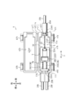
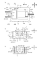
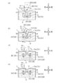
- FIG. 1 It is a figure which showed the overall structure of the connecting mechanism which concerns on one Embodiment of this invention, and is the figure which showed the state which the joint case was opened. It is a figure which showed the structure of the slider provided in the connection mechanism of FIG. 1, (a) is a view seen from above, (b) is seen from the front in the direction of arrow X1 in FIG. 2 (a). FIG. 2C is a view showing a cross section seen from the front in the direction of arrow X2 in FIG. 2A. It is a figure which showed the assembling procedure of the slider and the cable provided in the connection mechanism of FIG. 1 with time, and (a) is the figure which showed the state which one cable which passed through the passage part reached the arrangement space.
- the vertical direction, the front-rear direction, and the horizontal direction of the connecting mechanism 1 are defined by the directions of the arrows shown in FIGS. 1 to 5. Describe.
- “upper” in the above “vertical direction” refers to the sliding surface 31a below the sliding surface 31a with reference to the sliding surface 31a of the slider 3 that slides with the bottom surface 41a1 of the bottom member 41 by operating the inner cables 2A and 2B.
- the slider 3 (or the slider 103 in another embodiment) with respect to the joint case 4 may be arranged according to the direction of the arrow D shown in FIGS. 1, 2 (a), and 4 (a). The sliding direction is specified and described.
- the connecting mechanism 1 in the present embodiment is a mechanism for transmitting the operating force of the operating member to the operating member, and one cable attached to the operating member or the operating member and the other attached to the operating member or the operating member. Connect with the cable. That is, as shown in FIG. 1, for example, the connecting mechanism 1 connects at least two types of cables 2A and 2B, and applies the operating force applied to one cable 2A to the other cable 2B (or to the other cable 2B). The applied operating force is transmitted to one of the cables 2A).
- one end thereof (for example, the front end portion in the present embodiment) is connected to the connecting mechanism 1 side (slider 3 side described later), and the other end portion (for example, in the present embodiment). Is directly or indirectly connected to an operating member (not shown) for applying an operating force to the cable 2A.
- one end portion (for example, the rear end portion in the present embodiment) is connected to the connecting mechanism 1 side (slider 3 side), and the other end portion (for example, the present embodiment) is connected.
- the front end portion is directly or indirectly connected to a member (not shown) on the operating member side.
- the operating member is operated by transmitting the operating force applied to the operating member to the cable 2B via the cable 2A and the slider 3.
- the operating member only needs to be able to operate the cable 2A, and may be operated by manual operation such as a shift lever or a steering wheel, or may be operated by pulling the cable by electric drive.
- the operating member is not particularly limited as long as it is remotely controlled by operating the operating member, but for example, a locking mechanism in an opening / closing body such as a vehicle bonnet, a trunk, or a fuel lid, or a seat that locks the tilted state of the seat. A lock mechanism or the like can be adopted.
- the cables 2A and 2B need only be able to transmit the operating force applied by the operating member to the operating member, and for example, a known control cable can be adopted.
- a known control cable can be adopted.
- an inner cable inserted into the outer casing is adopted, but the present invention is not limited to this, and a control cable composed of only the inner cable 2 may be adopted. Good.
- the connecting mechanism 1 is mainly a joint having an inner cable 2A / 2B which is an example of a cable, a slider 3 which is connected to each end of the inner cable 2A / 2B, and a storage space S which slidably accommodates the slider 3.
- a case 4 and the like are provided.
- the slider 3 includes a bottom surface portion 31 (see FIG. 2B) having a sliding surface 31a that slides with respect to the joint case 4, and is joined by pulling either the inner cables 2A or 2B. It slides in the accommodation space S of the case 4.
- the inner cables 2A and 2B transmit the operating force applied by the operating member (not shown) including the seat lever or the like to the operating member (not shown) including the seat locking mechanism or the like via the slider 3. It is a member for.
- the inner cables 2A and 2B are slidably inserted into the outer casings 21A and 21B, respectively. Further, one end of the outer casing 21A (for example, the front end in the present embodiment) and one end of the outer casing 21B (for example, the rear end in the present embodiment) are both in the joint case 4.
- the inner cables 2A and 2B are fixed, and the outer casings 21A and 21B protect the inner cables 2A and 2B between both ends thereof.
- Cable ends 22A and 22B are attached to one end of the inner cable 2A (for example, the front end in the present embodiment) and one end of the inner cable 2B (for example, the rear end in the present embodiment).
- the inner cables 2A and 2B are both connected to the slider 3 via the cable ends 22A and 22B, respectively.
- the other end of the inner cable 2A (for example, the rear end in the present embodiment) and the other end of the inner cable 2B (for example, the front end in the present embodiment) are also formed. Cable ends (not shown) are provided respectively, and the inner cable 2A is connected to the operating member and the inner cable 2B is connected to the operating member via these cable ends.
- the inner cables 2A and 2B can be connected to the slider 3, and the operating force applied by the operating member can be transmitted to the operating member via the slider 3. It is not particularly limited as long as it has strength, and any shape such as a spherical shape, a columnar shape, or a prism can be used. The details of the shapes of these cable ends 22A and 22B will be described later.
- one inner cable 2A is connected to the slider 3 so as to extend from the slider 3 to one side (for example, the rear side in the present embodiment), and two inner cables are used.
- the cable 2B is connected to the slider 3 so as to extend from the slider 3 to the other side (for example, the front side in the present embodiment).
- the two inner cables 2B consist of the first inner cable 2B1 and the second inner cable 2B2 arranged in parallel with each other, and these first inner cables 2B1 and the second inner cable 2B2 are connected to each other at the ends. Has a long connecting end 2B3.
- the connecting end 2B3 is a cable end 22B provided on the inner cable 2B, has a function of connecting the inner cable 2B to the slider 3, and connects the first inner cable 2B1 and the second inner cable 2B2 in the longitudinal direction. It has the function of connecting to each other.
- the number of inner cables 2A and 2B can be appropriately changed depending on the application in which the connecting mechanism 1 is used. That is, as long as the inner cables are connected to each other via the slider 3, for example, one inner cable 2A may be provided with two or more and the other inner cable 2B may be provided with two or more. However, there may be a configuration in which two or more inner cables 2A on one side are provided and only one inner cable 2B on the other side is provided, or only one inner cable 2A on one side and one inner cable 2B on the other side are provided. It may be a provided configuration.
- the connecting mechanism 1 in the present embodiment has a plurality of inner cables so as to extend at least on one side because it is easy to lock the inner cables to the slider 3 and maintain the connected state. Is preferable.
- the cable end 22A of the inner cable 2A is locked to a first connecting portion 33 provided on one side (for example, the rear side in this embodiment) of the slider 3.
- the inner cable 2A is connected to the slider 3.
- the cable end 22B of the inner cable 2B is locked to a second connecting portion 34 provided on the other side (for example, the front side in this embodiment) of the slider 3.
- the inner cable 2B is connected to the slider 3.
- the slider 3 is a member that connects one inner cable 2A and the other inner cable 2B. Further, the slider 3 connects one inner cable 2A and the other inner cable 2B, so that the operating force applied to one inner cable 2A by the operating member is transmitted to the other inner cable 2B.
- the slider 3 is slidably accommodated in the accommodation space S of the joint case 4 so that the operating force applied by the operating member is transmitted to the operating member via the inner cables 2A and 2B.
- the slider 3 when the inner cable 2A is pulled rearward by the operating member, the slider 3 is locked to the cable end 22A of the inner cable 2A, and is therefore pulled by the inner cable 2A to form a joint. It slides toward the rear side in the accommodation space S of the case 4.
- the inner cable 2B in which the cable end 22B is locked to the slider 3 is also pulled to the rear side together with the slider 3. In this way, the operating force applied by the operating member is transmitted in this order to the inner cable 2A, the slider 3, and the inner cable 2B, and is transmitted to the operating member.
- the slider 3 has a substantially rectangular parallelepiped overall shape, and as described above, the slider 3 is via a first connecting portion 33 provided on the rear side portion and a second connecting portion 34 provided on the front side portion. Therefore, it can be connected to the cable end 22A of the inner cable 2A and the cable end 22B of the inner cable 2B, respectively. Further, the slider 3 is configured to be slidable in the sliding direction D (for example, in the front-rear direction in the present embodiment) in the accommodation space S of the joint case 4.
- the overall shape of the slider 3 is not limited to this embodiment, can be connected to the inner cables 2A and 2B, and slides in the accommodation space S of the joint case 4 in the sliding direction D. If possible, it can be appropriately modified according to the usage situation. The details of the slider 3 will be described later.
- the joint case 4 is an accommodating member that slidably accommodates the slider 3.
- the joint case 4 includes a bottom side member 41 having a bottom surface 41a1 and a lid side member 42 having a lid surface 42a1, and the lid side member 42 can be opened and closed with respect to the bottom side member 41.
- the bottom side member 41 has a bottom portion 41a having a bottom surface 41a1 on which the slider 3 slides, a pair of side wall portions 41b standing opposite to each other from the bottom portion 41a, and extending in the sliding direction D of the slider 3.
- a pair of end wall portions 41c standing opposite to each other at both ends of the sliding direction D in the bottom portion 41a are provided, and the accommodation space S is composed of the bottom portion 41a, the side wall portion 41b, and the end wall portion 41c. Has been done.
- the slider 3 can slide in the direction of transmitting the operating force to the inner cable 2B (or the inner cable 2A). It is configured in.
- a gap similar to the dimension in the width direction of the slider 3 (parallel to the bottom surface 41a1 and orthogonal to the sliding direction D) is provided so that the slider 3 is linearly guided and slides.
- a pair of side wall portions 41b are provided in parallel, and a substantially rectangular parallelepiped accommodation space S extending in the sliding direction D of the slider 3 is formed.
- the accommodation space S not only has a guide function for guiding the sliding direction of the slider 3, but also accommodates the slider 3 when assembling the inner cables 2A and 2B to the joint case 4, for example. It also has a holding function to hold the assembly posture of.
- the lid-side member 42 includes a lid portion 42a having a lid surface 42a1 covering the accommodation space S of the bottom-side member 41, an engaging portion 42b that engages with the bottom-side member 41, and the like, and engages with the bottom-side member 41. By doing so, the state in which the accommodation space S is closed is maintained. Further, the lid side member 42 is connected to the bottom side member 41 via a hinge 43, and is configured to be openable and closable with respect to the bottom side member 41 centering on the hinge 43.
- the lid side member 42 is formed with an engaging portion 42b shown as an engaging claw, and the lid side member 42 covers the bottom side member 41 to close the accommodation space S, and at the same time, the bottom side.
- the engaging portion 42b By engaging the engaging portion 42b with the engaged portion 41d formed on the member 41, the closed state of the accommodation space S is maintained. Thereby, the slider 3 accommodated in the accommodating space S of the bottom side member 41 can be prevented from jumping out of the accommodating space S and falling off by the lid surface 42a1 of the lid side member 42.
- the configuration of the engaging portion 42b provided on the lid side member 42 and the engaged portion 41d provided on the bottom side member 41 is not limited to this embodiment, and may be another engaging structure. You may.
- the end wall portion 41c provided on one side of the sliding direction D (for example, the rear side in the present embodiment) can be engaged with the casing end 23A provided at the front end portion of the outer casing 21A.
- First fixing portion 41c1 is formed, and by engaging the casing end 23A with the first fixing portion 41c1, the front end portion of the outer casing 21A does not separate from the bottom member 41, and the joint case 4 Is fixed to.
- the end wall portion 41c provided on the other side of the sliding direction D (for example, the front side in the present embodiment) has a casing end 23B provided at the rear end portion of the outer casing 21B.
- An engageable second fixing portion 41c2 is formed, and when the casing end 23B is engaged with the second fixing portion 41c2, the rear end portion of the outer casing 21B is separated from the bottom side member 41. It is fixed to the joint case 4 without any.
- a reduced diameter portion 23A1 having a reduced cross-sectional shape as compared with other regions is provided in the middle portion of the sliding direction D at the casing end 23A, and the first fixed portion 41c1 is provided.
- a reduced diameter portion 23B1 having a reduced cross-sectional shape as compared with other regions is provided in the middle portion of the casing end 23B in the sliding direction D, and the second fixed portion 41c2 is provided on the outer circumference of the reduced diameter portion 23B1.
- the outer casing 21B is prevented from being detached from the joint case 4 by forming the concave portion that can be engaged with the second fixing portion 41c2 and engaging the reduced diameter portion 23B1 with the second fixing portion 41c2.
- the engagement structure between these casing ends 23A and 23B and the first fixing portion 41c1 and the second fixing portion 41c2 is not limited to this embodiment and does not separate from the bottom member 41. Any configuration may be used as long as it can be securely fixed to the joint case 4.
- the slider 3 includes a sliding surface 31a that can slide with respect to the bottom surface 41a1 of the bottom member 41, and a pair of contact surfaces 32a that can contact the side wall portion 41b of the bottom member 41.
- a first connecting portion 33 and a second connecting portion 34 are provided on one side (rear side) and the other side (front side) of 31a, respectively.
- the slider 3 is configured to have a substantially rectangular parallelepiped shape as a whole, and is contained in the accommodation space S (see FIG. 1) of the joint case 4.
- the side surface of the bottom member 41 located on the bottom surface 41a1 side functions as a sliding surface 31a and faces the side wall portion 41b of the bottom member 41 in the width direction (parallel to the bottom surface 41a1 and parallel to the bottom surface 41a1).
- a pair of side surfaces provided on both sides of the sliding direction D function as the contact surface 32a.
- the sliding surface 31a is formed in a flat shape, but the present invention is not limited to this, and for example, a recess (or a through hole) or the like is arbitrarily provided to form the bottom side member 41.
- the configuration may be such that the frictional resistance with the bottom surface 41a1 is reduced.
- the first connecting portion 33 engages with the cable end 22A provided at the front end portion of the inner cable 2A, and connects the inner cable 2A to the slider 3. As shown in FIG. 2A, for example, the first connecting portion 33 communicates with the first passage portion 33a through which the inner cable 2A can be inserted and the first passage portion 33a, and can accommodate the cable end 22A. It is composed of one cable end accommodating portion 33b.
- the first passage portion 33a has a groove shape that penetrates the rear end surface 39a of the slider 3 in the sliding direction D and extends downward from the upper surface of the slider 3 as shown in FIG. 2C. It is formed. Further, the dimension (gap) in the width direction (left-right direction) of the first passage portion 33a is set to be substantially the same as the wire diameter of the inner cable 2A.
- the first cable end accommodating portion 33b is formed in a concave shape communicating with the first passage portion 33a at the rear portion of the upper surface of the slider 3, and the dimension in the width direction (left-right direction) is abbreviated as the outer diameter of the cable end 22A. It is set to be equivalent.
- the first cable end accommodating portion 33b is formed so as to communicate with the second cable end accommodating portion 34b, which will be described later, but the first cable end accommodating portion 33b is not limited to this. However, it may be provided independently of the second cable end accommodating portion 34b as long as it has a dimension in the length direction (in the front-rear direction in the present embodiment) that can accommodate the cable end 22A.
- the inner cable 2A is inserted into the first passage portion 33a, the cable end 22A is accommodated in the first cable end accommodating portion 33b, and the end surface 39a of the slider 3 (more specifically). Specifically, by bringing the rear end surface 22A1 of the cable end 22A into contact with the rear end surface 22A1 of the slider 3 having the end surface 39a, the cable end 22A engages with the end surface 39a of the slider 3 and is inner.
- the cable 2A is connected to the slider 3 by the first connecting portion 33.
- the configuration of the first connecting portion 33 is not limited to this embodiment, and is equivalent to, for example, the second connecting portion 34 described later and the fourth connecting portion 134 of the slider 103 in another embodiment. May be adopted.
- the second connecting portion 34 is an example of an embodiment embodying the present invention, and engages with a cable end 22B provided at the rear end portion of the inner cable 2B to connect the inner cable 2B to the slider 3.
- the second connecting portion 34 has a disconnection suppressing portion 34a that suppresses the inner cable 2B from disconnecting from the slider 3, and a second cable end accommodating portion 34b that accommodates the cable end 22B.
- the detachment suppressing unit 34a is mainly composed of an arrangement space 35, an introduction port 36, a passage unit 37, a first regulation unit 38, a second regulation unit 39, and the like.
- the inner cable 2B extending from the cable end 22B toward the sliding direction D (forward in this embodiment) of the slider 3 is arranged in a state where the inner cable 2B is connected to the slider 3. It is a space.
- the arrangement space 35 is a space that penetrates the end surface 39b on the front side of the slider 3 in the sliding direction D.
- the bottom portion 41a of the joint case 4 (more specifically, the bottom side member 41).
- two inner cables 2B (more specifically, the first inner cable 2B1 and the second inner cable 2B2) arranged in parallel with each other are provided.
- the first inner cable 2B1 and the second inner cable 2B2 are arranged in the arrangement space 35 in a state of being separated in the width direction (left-right direction).
- the introduction port 36 is a gap provided as an entrance when the inner cable 2B is introduced into the arrangement space 35.
- the introduction port 36 is provided on the upper side of the arrangement space 35, has a gap equal to or larger than the wire diameter of each inner cable 2B (first inner cable 2B1 or second inner cable 2B2), and is perpendicular to the axis of the inner cable 2B. It is configured to open in the direction (in the present embodiment, the left-right direction).
- the introduction port 36 is sequentially moved in the direction perpendicular to the axis (in the present embodiment, the vertical direction) for each inner cable 2B (first inner cable 2B1 or second inner cable 2B2). It is configured so that it can pass through the first inner cable 2B1 and the second inner cable 2B2.
- the introduction port 36 is configured by the gap between the pair of top plate portions 51 constituting the first regulation portion 38.
- the passage portion 37 is a space for guiding each inner cable 2B that has passed through the introduction port 36 to the arrangement space 35. Similar to the above-mentioned arrangement space 35, the passage portion 37 is a space that penetrates the front end surface 39b of the slider 3 in the sliding direction D, communicates with the arrangement space 35 and the introduction port 36, and is an inner cable. It is set so as to have a gap substantially equal to the wire diameter of 2B, and each inner cable 2B is configured to be movable to the arrangement space 35 via the introduction port 36.
- the passage portion 37 is formed by the gap between the pair of guide portions 52 constituting the second regulation portion 39, and the passage portion 37 is introduced with the arrangement space 35. It is provided so as to extend in the direction perpendicular to the width direction (horizontal direction) of the slider 3 (vertical direction in the present embodiment) with the mouth 36.
- the inner cable 2B arranged in the arrangement space 35 suddenly moves in a direction parallel to the direction in which the passage portion 37 extends (vertical direction) (for example, in the present embodiment, upward). Sometimes, it is a part for blocking the moving direction of the inner cable 2B.
- the first regulating portion 38 is provided on the side opposite to the bottom surface portion 31 side in the arrangement space 35, that is, on the upper side.
- the first regulating portion 38 is provided from the upper end portion of the pair of side wall portions 32 to the center portion in the width direction of the slider 3. It is composed of a pair of top plate portions 51 that extend toward each other and form an end surface 39b on the front side of the slider 3.
- the first inner cable 2B1 and the second inner cable 2B2 constituting the inner cable 2B are arranged in the arrangement space 35 in a state of being separated in the width direction (left-right direction), and the first The pair of top plate portions 51 constituting the regulating portion 38 are provided so as to be located at least above the first inner cable 2B1 and the second inner cable 2B2.
- the bottom surface portion of the top plate portion 51 is formed. It comes into contact with the end surface on the 31 side (lower end surface in this embodiment), and the top plate portion 51 functions as the first regulation portion 38.
- these pair of top plate portions 51 are set so that the gap between the end faces on the sides facing each other is equal to or larger than the wire diameter of the first inner cable 2B1 (or the second inner cable 2B2).
- the introduction port 36 is formed by a gap between the pair of top plate portions 51.
- the second regulation unit 39 is a portion for restricting the movement of the inner cable 2B arranged in the arrangement space 35 to the passage unit 37.
- the second regulation unit 39 is provided adjacent to the first regulation unit 38 described above.
- the second regulation unit 39 is an extension end portion (that is, an extension end portion) of a pair of top plate portions 51 constituting the first regulation unit 38.
- the pair of top plate portions 51 extends from the end portion on the side opposite to the side wall portion 32 side toward the bottom surface portion 31 side in the direction perpendicular to the width direction of the slider 3 (downward in the present embodiment). It is composed of a pair of guide portions 52 provided in each of the above.
- an external force is unexpectedly applied to the first inner cable 2B1 and the second inner cable 2B2 arranged in the arrangement space 35 in a state of being separated in the width direction (left-right direction), and the first inner cable 2B1 (or When the second inner cable 2B2) tries to move to the passage portion 37 while floating with the second inner cable 2B2 (or the first inner cable 2B1) as a fulcrum, the first inner cable 2B1 (or the second inner cable 2B1) 2B2) comes into contact with the side surface of the guide portion 52 on the side facing the side wall portion 32, and the side surface functions as the second regulation portion 39.
- these pair of guide portions 52 are set so that the gap between the side surfaces facing each other is substantially the same as the wire diameter of the first inner cable 2B1 (or the second inner cable 2B2).
- the passage portion 37 described above is composed of a gap between the pair of guide portions 52.
- the second cable end accommodating portion 34b includes the arrangement space 35 (see FIG. 2B), the introduction port 36, and the passage portion 37 in the front portion of the upper surface of the slider 3. It is formed in a concave shape that communicates with each other. Further, the second cable end accommodating portion 34b has a cable end 22B in a state where the rear end portions of the first inner cable 2B1 and the second inner cable 2B2 constituting the inner cable 2B are arranged so as to penetrate the arrangement space 35. To accommodate.
- the second cable end accommodating portion 34b has a pair of inner side surfaces 32b provided on both sides in the width direction (left-right direction) and formed on the side wall portion 32, and the pair of inner side surfaces 32b.
- the inner side surface 32b functions as a third regulating unit 40 that regulates the rotation of the cable end 22B housed in the second cable end accommodating portion 34b.
- the cable end 22B provided on the inner cable 2B is composed of a long connecting end 2B3 that connects the first inner cable 2B1 and the second inner cable 2B2 in the longitudinal direction.
- the cable end 22B is oriented in the longitudinal direction in the width direction.
- the pair of inner side surfaces 32b are provided so as to face both end surfaces of the accommodated cable end 22B in the longitudinal direction (left-right direction in the present embodiment).
- the lid side member 42 is in an open state, and the sliding surface 31a (see FIG. 2B) is the bottom surface of the bottom side member 41.
- the slider 3 is inserted into the accommodation space S of the bottom side member 41 while facing the 41a1 side.
- the position where the slider 3 is inserted may be any position in the sliding direction D, but the work of connecting the inner cables 2A and 2B to the slider 3 is performed later. Therefore, in order to secure a work space in advance, it is desirable to set it near the central portion of the sliding direction D.
- the slider 3 is inserted into the accommodation space S in a state where the second connecting portion 34 is directed forward and the first connecting portion 33 is directed rearward, but the present invention is limited to this.
- the slider 3 can be changed as appropriate depending on the application in which the connecting mechanism 1 is used, and the slider 3 can be changed depending on the state in which the first connecting portion 33 is directed forward and the second connecting portion 34 is directed rearward. It may be inserted into the accommodation space S.
- the work of connecting the slider 3 and the inner cables 2A and 2B is subsequently performed.
- one inner cable 2A is connected to the slider 3, and then the other inner cable 2B is connected to the slider 3, but the present invention is limited to this. Instead, the other inner cable 2B may be connected to the slider 3, and then the other inner cable 2A may be connected to the slider 3.
- the connection work between the inner cable 2A and the slider 3 is performed according to the following procedure.
- the inner cable 2A is pulled out by a predetermined length from the casing end 23A provided at the end of the outer casing 21A (in the present embodiment, the front end).
- the end portion of the inner cable 2A (in the present embodiment, the front end portion) pulled out from the casing end 23A is inserted into the first connecting portion 33 of the slider 3 from above, and is shown in FIG. 2A.
- the inner cable 2A is inserted into the first passage portion 33a, the cable end 22A is accommodated in the first cable end accommodating portion 33b, and the cable end 22A is engaged with the end surface 39a of the slider 3.
- the end portion (front end portion) of the inner cable 2A is connected to the slider 3.
- the casing end 23A of the outer casing 21A is inserted into the first fixing portion 41c1 of the bottom side member 41 from above, and the casing end 23A is first fixed via the reduced diameter portion 23A1. Engage with 41c1. As a result, the end portion of the outer casing 21A is fixed to the joint case 4, and the connection work between the slider 3 and one inner cable 2A is completed.
- the casing end 23A of the outer casing 21A is fixed to the joint case 4. It is not limited, and in consideration of work efficiency and the like, after fixing the casing end 23A of the outer casing 21A to the joint case 4, the end portion (front end portion) of the inner cable 2A is connected to the slider 3. May be. Further, after connecting the end portion (front end portion) of the inner cable 2A to the slider 3, the end portion (rear side end portion) of the inner cable 2B is connected to the slider 3 according to the procedure described later, and then. , The casing end 23A of the outer casing 21A and the casing end 23B of the outer casing 21B may be fixed together to the joint case 4.
- connection work between one inner cable 2A and the slider 3 is completed, the connection work between the other inner cable 2B and the slider 3 is subsequently performed.
- the connection work between the other inner cable 2B and the slider 3 is performed according to the following procedure. First, the inner cable 2B is pulled out by a predetermined length from the casing end 23B provided at the end of the outer casing 21B (in the present embodiment, the rear end). Next, the end portion of the inner cable 2B (the rear end portion in the present embodiment) pulled out from the casing end 23B is inserted into the second connecting portion 34 of the slider 3 from above, and FIG. 2A is shown.
- the inner cable 2B is inserted into the disconnection suppressing portion 34a, the cable end 22B (connecting end 2B3) is accommodated in the second cable end accommodating portion 34b, and the cable end 22B (connecting end 2B3) is slidered. Engage with the end face 39b of 3. As a result, the end portion (rear end portion) of the inner cable 2B is connected to the slider 3.
- first inner cable 2B1 and second inner cable 2B2 are provided, and these inner cables 2B are introduced one by one in order. It invades the passage portion 37 from the 36 and is guided to the arrangement space 35 by the passage portion 37.
- first of the two inner cables 2B one of the inner cables 2B (first inner cable 2B1 in the present embodiment) is first, and the other inner cable (second in the present embodiment).
- the first inner cable 2B1 is inserted into the passage portion 37 from the introduction port 36 in a state of facing the slider 3 side (lower side in the present embodiment) with respect to the inner cable 2B1).
- the first inner cable 2B1 that has penetrated into the passage portion 37 is moved to the bottom surface portion 31 side of the slider 3 along the passage portion 37, and is moved into the arrangement space 35 as shown in FIG. 3A.
- the first inner cable 2B1 is reached.
- the second inner cable 2B2 has not yet entered the passage portion 37 and is located in the vicinity of the introduction port 36. ..
- the cable end 22B (connecting end 2B3) is moved to the slider 3 in the second cable end accommodating portion 34b. While moving slightly in the width direction (horizontal direction), it is rotated about a virtual axis parallel to the sliding direction D (see FIG. 1). As a result, the first inner cable 2B1 is moved toward the side separated from the passage portion 37 (in the present embodiment, the right side with respect to the passage portion 37) while drawing a substantially arc-shaped locus, and the second inner cable 2B1 is moved. The inner cable 2B2 is moved toward the side close to the introduction port 36 while drawing a substantially arcuate locus.
- the cable end 22B (connecting end 2B3) is further rotated around the axis of the first inner cable 2B1 that has reached a position separated from the passage portion 37.
- the two inner cables 2B2 are moved to the arrangement space 35 while being guided by the passage portion 37 while pressing the side surface of one side (left side in the present embodiment) of the passage portion 37.
- the slider 3 is formed of, for example, a member having an elastic function such as resin, and the pair of guide portions 52 constituting the passage portion 37 are configured to be bendable with the base portion on the top plate portion 51 side as a fulcrum. ing.
- the second inner cable 2B2 is moved to the arrangement space 35 while pressing the side surface of one side (left side) of the passage portion 37 and widening the gap of the passage portion 37.
- the arrangement space 35 constituting the detachment suppressing portion 34a of the slider 3 in the present embodiment is the inner cable of one of the first inner cable 2B1 and the second inner cable 2B2 (for example, the first inner cable 2B1). Moves through the passage portion 37 via the introduction port 36, and when the cable end 22B (connecting end 2B3) reaches a position separated from the passage portion 37 by rotation at the second cable end accommodating portion 34b, the first The other inner cable (for example, the second inner cable 2B2) of the one inner cable 2B1 and the second inner cable 2B2 is configured to be movable from the passage portion 37 to the arrangement space 35.
- the cable end 22B engages with the end surface 39b of the slider 3, and the end of the inner cable 2B. (Rear end) is connected to the slider 3.
- the casing end 23B of the outer casing 21B is inserted into the second fixing portion 41c2 of the bottom side member 41 from above, and the casing end 23B is fixed to the second fixing portion 23B via the reduced diameter portion 23B1. Engage with 41c2.
- the end portion of the outer casing 21B is fixed to the joint case 4, and the connection work between the slider 3 and the other inner cable 2B is completed.
- connection work between the slider 3 and the inner cables 2A and 2B may be performed either before or after the slider 3 is inserted into the accommodation space S of the bottom member 41, but the slider 3 may be connected in advance.
- the slider 3 By inserting the slider 3 into the accommodation space S of the bottom member 41, the slider 3 is held in a posture by the bottom member 41, and the subsequent slider 3 and the inner cables 2A and 2B can be easily connected.
- the lid side member 42 When the connection work between the slider 3 and the inner cables 2A and 2B is completed, the lid side member 42 is closed and the engaging portion 42b is engaged with the engaged portion 41d of the bottom side member 41 to engage the lid side member 42. Keeps the closed state of. As a result, the accommodation space S of the bottom side member 41 is firmly maintained in a closed state by the lid side member 42. For example, an external force is suddenly applied to the slider 3 via the inner cables 2A and 2B. It is possible to prevent the slider 3 from falling off from the joint case 4. Then, when the closing work of the lid side member 42 in the joint case 4 is completed, the assembling work of the connecting mechanism 1 is completed.
- connection mechanism 101 in another embodiment has substantially the same configuration as the connecting mechanism 1 described above, the configuration of the fourth connecting portion 134 mainly provided on the other side (front side in this embodiment) of the slider 103 is described. It is different from the connection mechanism 1 described above. Therefore, in the following description, the differences from the connection mechanism 1 described above will be mainly described, and the description of the configuration equivalent to the connection mechanism 1 will be omitted.
- the slider 103 includes a sliding surface 131a that is slidable with respect to the bottom surface 141a1 of the bottom member 141 of the joint case 104, and one side (rear side) and the other side (front side) of the sliding surface 131a are provided with a sliding surface 131a.
- a third connecting portion 133 and a fourth connecting portion 134 are provided, respectively.
- the joint case 104, the sliding surface 131a, and the third connecting portion 133 have the same configurations as the joint case 4, the sliding surface 31a, and the first connecting portion 33 in the connecting mechanism 1 described above. Therefore, the description of the description is omitted.
- the fourth connecting portion 134 is an example of the embodiment embodying the present invention, and engages with the cable end 122B provided at the rear end portion of the inner cable 102B to connect the inner cable 102B to the slider 103.
- the fourth connecting portion 134 has a disconnection suppressing portion 134a that suppresses the inner cable 102B from disconnecting from the slider 103, and a third cable end accommodating portion 134b that accommodates the cable end 122B. Since the inner cable 102B and the cable end 122B have the same configurations as the inner cable 2B and the cable end 22B in the connection mechanism 1 described above, the description thereof will be omitted.
- the detachment suppressing unit 134a is mainly composed of an arrangement space 135, an introduction port 136, a passage unit 137, a fourth regulation unit 138, a fifth regulation unit 139, and the like. Since the arrangement space 135, the introduction port 136, and the passage portion 137 have the same configurations as the arrangement space 35, the introduction port 36, and the passage portion 37 in the connection mechanism 1 described above, the description of the description is omitted. To do.
- the inner cable 102B arranged in the arrangement space 135 suddenly moves in a direction parallel to the direction in which the passage unit 137 extends (vertical direction) (for example, in another embodiment, upward). Sometimes, it is a part for blocking the moving direction of the inner cable 2B.
- the fourth regulation unit 138 is provided on the side opposite to the bottom surface portion 131 side in the arrangement space 135, that is, on the upper side. For example, in another embodiment, one of the pair of side wall portions 132 (for example, another embodiment) is provided.
- first inner cable 102B1 and the second inner cable 2B2 constituting the inner cable 102B are arranged in the arrangement space 135 in a state of being separated in the width direction (left-right direction), and constitute the fourth regulation unit 138.
- the top plate portion 151 is provided so as to be continuously located at least above the first inner cable 102B1 and the second inner cable 102B2.
- the bottom surface portion of the top plate portion 151 is formed. It comes into contact with the end surface on the 131 side (lower end surface in this embodiment), and the top plate portion 151 functions as the fourth regulation portion 138.
- the top plate portion 151 is set so that the gap with the side wall portion 132 on the other side (right side) is equal to or larger than the wire diameter of the first inner cable 102B1 (or the second inner cable 102B2).
- the mouth 136 is formed by a gap between the top plate portion 151 and the side wall portion 132 on the other side (right side).
- the fifth regulation unit 139 is a portion for restricting the movement of the inner cable 102B arranged in the arrangement space 135 to the passage unit 137.
- the fifth regulation unit 139 is provided adjacent to the fourth regulation unit 138 described above, and for example, in another embodiment, the extending end portion (that is, the top plate) of the top plate portion 151 constituting the fourth regulation unit 138.
- a guide provided so as to extend from the end portion of the portion 151 facing the side wall portion 132 toward the bottom surface portion 131 in a direction perpendicular to the width direction of the slider 103 (downward in another embodiment). It is composed of a part 152.
- the guide portion 152 is set so that the gap between the guide portion 152 and the side wall portion 132 on the other side (right side) is substantially the same as the wire diameter of the first inner cable 102B1 (or the second inner cable 102B2).
- the passage portion 137 is composed of a gap between the guide portion 152 and the side wall portion 132 on the other side (right side).
- the third cable end accommodating portion 134b has substantially the same configuration as the second cable end accommodating portion 34b in the connection mechanism 1 described above, while the cable is used when connecting the slider 3 and the inner cable 102B, as will be described later.
- the shape is slightly extended toward the passage portion 137.
- the shape of the third cable end accommodating portion 134b is not limited to that of another embodiment.
- the configuration of the cable end 122B in the inner cable 2B is appropriately redesigned to accommodate the second cable end. It may have the same configuration as the part 34b.
- the connecting mechanism 101 in another embodiment having the above configuration is assembled according to a procedure substantially equivalent to that of the connecting mechanism 1 described above, while the procedure for inserting the inner cable 102B into the detachment suppressing portion 134a. Is different from the connection mechanism 1 described above.
- the procedure for inserting the inner cable 102B into the detachment suppressing portion 134a will be described below with reference to FIG. 5, but other work procedures will be described because they follow the same procedure as the connection mechanism 1 described above. The description of is omitted.
- the first inner cable 102B1 is inserted into the passage portion 137 from the introduction port 136.
- the first inner cable 102B1 that has penetrated into the passage portion 137 is moved to the bottom surface portion 131 side of the slider 103 along the passage portion 137, and is moved into the arrangement space 135 as shown in FIG. 5 (a).
- the first inner cable 102B1 is reached.
- the second inner cable 102B2 has not yet entered the passage portion 137 and is located in the vicinity of the introduction port 136. ..
- the cable end 122B is inserted into the third cable end accommodating portion 134b in the width direction of the slider 3 and in the passage.
- the first inner cable 102B1 is moved to a side away from the portion 137 (on the left side in another embodiment) to reach a substantially central portion in the width direction in the arrangement space 135.
- the cable end 122B is further moved in the width direction (left direction) of the slider 3, and the virtual axis parallel to the sliding direction D (see FIG. 4A). Rotate around the heart.
- the first inner cable 102B1 is moved toward the side (left side) away from the passage portion 137 while drawing a substantially arcuate locus
- the second inner cable 102B2 is on the side close to the introduction port 136. It is moved toward the direction while drawing a substantially arcuate locus.
- the second inner cable 102B2 is further rotated around the axis of the first inner cable 102B1 that has reached a position separated from the passage portion 137, so that the second inner cable 102B2 is further rotated. , While being guided by the passage portion 137, it is moved to the arrangement space 135.
- the arrangement space 135 in another embodiment is the inner cable of one of the first inner cable 102B1 and the second inner cable 102B2 (for example, the first inner cable), similarly to the arrangement space 135 in the connection mechanism 1 described above.
- the cable 102B1 moves through the passage portion 137 via the introduction port 136 and reaches a position separated from the passage portion 137 by rotation of the cable end 122B at the third cable end accommodating portion 134b
- the first inner The other inner cable (for example, the second inner cable 102B2) of the cable 102B1 and the second inner cable 102B2 is configured to be movable from the passage portion 137 to the arrangement space 135.
- the cable end 122B engages with the end surface 139b of the slider 103 (see FIG. 4A), and the inner cable 102B
- the end portion (rear end portion) is connected to the slider 103.
- the connecting mechanism 1 (or connecting mechanism 101) in the present embodiment includes an inner cable 2B (or an inner cable 102B) having a cable end 22B (or a cable end 122B) at an end, and an inner cable 2B (inner).
- a slider 3 (or slider 103) having a second connecting portion 34 (or a fourth connecting portion 134) connected to the end of the cable 102B) and an accommodating space S slidably accommodating the slider 3 (slider 103).
- the second connecting portion 34 (fourth connecting portion 134) includes a second cable end accommodating portion 34b (or a third cable end accommodating portion 134b) accommodating the cable end 22B (cable end 122B) and an inner cable 2B (inner cable 2B).
- the inner cable 102B) has a detachment suppressing portion 34a (or a detachment suppressing portion 134a) that suppresses the detachment from the slider 3 (slider 103).
- the detachment suppressing portion 34a includes the arrangement space 35 (or the arrangement space 135), the introduction port 36 (or the introduction port 136), the passage portion 37 (or the passage portion 137), and the first regulation.
- the arrangement space 35 (arrangement space 135) extends in the sliding direction D of the slider 3 (slider 103), and the inner cable 2B (inner cable 102B) is connected to the slider 3 (slider 103). This is a space in which the inner cable 2B (inner cable 102B) extending from the end 22B (or the cable end 122B) is arranged.
- the introduction port 36 (introduction port 136) is opened in the direction perpendicular to the axis of the inner cable 2B (inner cable 102B) with a gap equal to or larger than the wire diameter of the inner cable 2B (inner cable 102B), and is perpendicular to the axis. It is a gap that can be moved and passed through the inner cable 2B (inner cable 102B).
- the passage portion 37 (passage portion 137) communicates with the arrangement space 35 (arrangement space 135) and the introduction port 36 (introduction port 136), and the inner cable 2B (inner cable 102B) is connected to the introduction port 36 (introduction port 136). ) To the arrangement space 35 (arrangement space 135).
- the inner cable 2B (inner cable 102B) arranged in the arrangement space 35 (arrangement space 135) extends in the direction in which the passage portion 37 (or the passage portion 137) extends. This is a portion that blocks the moving direction of the inner cable 2B (inner cable 102B) when it moves in a direction parallel to the above.
- the gap between the introduction ports 36 is equal to or larger than the wire diameter of the inner cable 2B (inner cable 102B).
- the introduction port 36 is smoothly set. It can be guided to the passage portion 37 (passage portion 137) through the mouth 136), and the inner cable 2B (inner) is prevented from being bent at the end of the inner cable 2B (inner cable 102B).
- the end of the cable 102B) can be easily connected to the slider 3 (slider 103).
- the inner cable 2B is provided by the first regulation unit 38 (fourth regulation unit 138). It is possible to prevent the end portion of the 102B) from moving to the side opposite to the sliding surface 31a (sliding surface 131a) side of the joint case 4 (joint case 104) and falling out of the slider 3 (slider 103). ..
- the disconnection suppressing unit 34a (disengagement suppressing unit 134a) is provided adjacent to the first regulation unit 38 (fourth regulation unit 138) and is provided as an arrangement space.
- the second regulation unit 39 (or the fifth regulation unit 139) that regulates the movement of the inner cable 2B (inner cable 102B) arranged in the 35 (arrangement space 135) to the passage portion 37 (passage portion 137) is It is characterized by having.
- the end of the inner cable 2B (inner cable 102B) arranged in the arrangement space 35 (arrangement space 135) is passed through again by the second regulation unit 39 (or the fifth regulation unit 139). It is possible to prevent the slider 3 (slider 103) from falling out of the slider 3 (slider 103) through the introduction port 36 (introduction port 136) after passing through the portion 37 (passage portion 137).
- the inner cable 2B is the first inner cable 2B1 (or the first inner cable 102B1) and the second inner cable arranged in parallel with each other. It has a cable 2B2 (or a second inner cable 102B2) and a connecting end 2B3 that connects the first inner cable 2B1 (first inner cable 102B1) and the second inner cable 2B2 (second inner cable 102B2).
- the arrangement space 35 is the inner cable 2B (inner cable 102B) of one of the first inner cable 2B1 (first inner cable 102B1) and the second inner cable 2B2 (second inner cable 102B2).
- the connecting end 2B3 that connects the first inner cable 2B1 and the second inner cable 2B2 is a long length that connects the first inner cable 2B1 and the second inner cable 2B2 in the longitudinal direction.
- the cable end 22B was rotated while the ends of the first inner cable 2B1 and the second inner cable 2B2 were arranged in the arrangement space 35 in a state of penetrating the cable end 22B. It is characterized by having a third regulating portion 40 that sometimes comes into contact with both end faces in the longitudinal direction of the cable end 22B to regulate rotation.
- the third regulatory unit Since the fluttering of the cable end 22B is regulated by 40, the first inner cable 2B1 and the second inner cable 2B2 are twisted in the twisting direction (for example, either the first inner cable 2B1 or the second inner cable 2B2) together with the cable end 22B. It is moved in the direction of rotating one center and the other), and these first inner cable 2B1 and second inner cable 2B2 suddenly pass through the passage portion 37 and fall out of the slider 3 through the introduction port 36. Can be prevented.
- the detachment suppressing portion 34a is a pair provided in a direction perpendicular to the bottom surface portion 31 on the bottom surface side of the joint case 4 and the extending direction of the inner cable 2B, which divides the arrangement space 35.
- the first regulating portion 38 is composed of a pair of top plate portions 51 provided on the side opposite to the bottom surface portion 31 side of the arrangement space 35, and the introduction port 36 is a pair of top plate portions.
- the passage portion 37 is composed of a gap of 51, and the passage portion 37 is characterized by being composed of a gap of a pair of guide portions 52 provided on the opposite side of the side wall portion 32 in each of the pair of top plate portions 51.
- the pair of top plate portions 51 extending from the end portion of the side wall portion 32 can simultaneously have the function as the first regulating portion 38 and the function as the introduction port 36.
- the configuration of the connecting portion 34 can be simplified.
Landscapes
- Engineering & Computer Science (AREA)
- General Engineering & Computer Science (AREA)
- Health & Medical Sciences (AREA)
- Oral & Maxillofacial Surgery (AREA)
- Mechanical Engineering (AREA)
- Flexible Shafts (AREA)
- Electric Cable Arrangement Between Relatively Moving Parts (AREA)
Abstract
ケーブルの端部と連結する連結部を有するスライダーを備える連結機構であって、連結部は、ケーブルエンドを収容するケーブルエンド収容部、及びケーブルの離脱を抑制する離脱抑制部を有し、離脱抑制部は、ケーブルがスライダーに連結された状態で、ケーブルエンドから延出したケーブルが配置される配置空間、ケーブルの軸と垂直方向にケーブルの線径以上の隙間で開口し、軸と垂直方向に移動させてケーブルを通過可能な導入口、配置空間と導入口とに連通し、ケーブルが導入口を介して配置空間へと移動可能な通路部、及び配置空間に配置されたケーブルが、通路部が延びる方向と平行な方向に移動したときに、ケーブルの移動方向を塞ぐ第一規制部を有する連結機構を用いることで、ジョイントケースに摺動可能に収容されるスライダーへのケーブルの組付けが容易であって、当該スライダーからケーブルが抜け落ちるのを防止することができる。
Description
本発明は、連結機構に関する。
従来から、操作部材に接続されたケーブル(以下、適宜「操作側ケーブル」と記載)と、作動部材に接続されたケーブル(以下、適宜「作動側ケーブル」と記載)とを連結し、これらの連結されたケーブルを介して、操作部材による操作力を作動部材に伝達する連結機構が知られている(例えば、「特許文献1」を参照)。
前記連結機構は、主に、スライダーと、当該スライダーを摺動可能に収容するジョイントケース等を備え、操作側ケーブルは、操作部材側との反対側の端部において、スライダーにおける摺動方向の一端部と連結され、また、作動側ケーブルは、作動部材側との反対側の端部において、スライダーにおける摺動方向の他端部と連結される。
前記連結機構は、主に、スライダーと、当該スライダーを摺動可能に収容するジョイントケース等を備え、操作側ケーブルは、操作部材側との反対側の端部において、スライダーにおける摺動方向の一端部と連結され、また、作動側ケーブルは、作動部材側との反対側の端部において、スライダーにおける摺動方向の他端部と連結される。
そして、操作部材による操作力によって操作側ケーブルを操作部材側へと引き寄せることにより、スライダーは、作動側ケーブルを伴いつつ、ジョイントケース内を摺動する。
これにより、操作部材による操作力は、操作側ケーブル、スライダー、作動側ケーブルと順に伝達し、作動部材に加えられる。
これにより、操作部材による操作力は、操作側ケーブル、スライダー、作動側ケーブルと順に伝達し、作動部材に加えられる。
ここで、ケーブルとスライダーとの連結箇所において、当該ケーブルは、その端部をスライダーの摺動方向側の側面に貫通させた状態によって、スライダーと連結される。
具体的には、例えば特許文献1において、スライダー(ジョイントピース)の摺動方向側の側面には、ジョイントケース(ケース)との摺動面側との反対側に開口し、且つ当該摺動方向に延びる延出部と、スライダー内に設けられ当該延出部と連通する係止部とが設けられている。一方、ケーブルの端部(操作部材または作動部材と連結される側の端部と、反対側の端部)の先端には、例えば球状のケーブルエンドが設けられている。
そして、ケーブルの端部は、係止部によってケーブルエンドを係止された状態にて、延出部の内部に挿入され、スライダーと貫通させた状態で連結される。
具体的には、例えば特許文献1において、スライダー(ジョイントピース)の摺動方向側の側面には、ジョイントケース(ケース)との摺動面側との反対側に開口し、且つ当該摺動方向に延びる延出部と、スライダー内に設けられ当該延出部と連通する係止部とが設けられている。一方、ケーブルの端部(操作部材または作動部材と連結される側の端部と、反対側の端部)の先端には、例えば球状のケーブルエンドが設けられている。
そして、ケーブルの端部は、係止部によってケーブルエンドを係止された状態にて、延出部の内部に挿入され、スライダーと貫通させた状態で連結される。
ところで、スライダーに連結されたケーブルが、当該スライダーの摺動方向に対して三次元的に異なる方向に配索されている場合、操作部材による操作力が作動部材に伝達される際、ケーブルの端部には、スライダーに対して三次元的に任意の方向に外力が加えられることとなり、当該外力の方向によっては、ケーブルの端部が上記延出部の開口側に向って移動され、スライダーからの脱落を引き起こす要因となる虞があった。
そこで、このような、ケーブルの端部がスライダーの延出部から脱落するのを防止するための手段として、当該延出部における開口の隙間のみを、ケーブルの線径に比べてやや小さく設定し、例えば、上記外力によって、ケーブルの端部が開口側に向かって移動された場合であっても、当該開口を通過してスライダーから脱落し難い構成とすることが考えられる。
しかしながら、このような構成においては、ケーブルの端部がスライダーから脱落するのを抑制することができる反面、上記開口を介してケーブルの端部をスライダーの延出部に押込んで組付ける際、上記開口による抗力を受けることになる。そのため、ケーブルの端部に折れ曲がり等が発生しないように慎重にスライダーへの組付けを行うと量産性が低下してしまい、ケーブルの剛性の低下しないようにケーブルの径を大きくすると配索の自由度が損なわれてしまう。
しかしながら、このような構成においては、ケーブルの端部がスライダーから脱落するのを抑制することができる反面、上記開口を介してケーブルの端部をスライダーの延出部に押込んで組付ける際、上記開口による抗力を受けることになる。そのため、ケーブルの端部に折れ曲がり等が発生しないように慎重にスライダーへの組付けを行うと量産性が低下してしまい、ケーブルの剛性の低下しないようにケーブルの径を大きくすると配索の自由度が損なわれてしまう。
本発明の目的は、ジョイントケースに摺動可能に収容されるスライダーへのケーブルの組付けが容易であって、当該スライダーからケーブルが抜け落ちるのを防止することができる連結機構を提供することにある。
本発明の解決しようとする課題は以上の如くであり、次にこの課題を解決するための手段を説明する。
即ち、本発明の連結機構は、ケーブルエンドを端部に有するケーブルと、前記ケーブルの端部と連結する連結部を有するスライダーと、前記スライダーを摺動可能に収容する収容空間を有するジョイントケースとを備える連結機構であって、前記連結部は、前記ケーブルエンドを収容するケーブルエンド収容部と、前記ケーブルの前記スライダーからの離脱を抑制する離脱抑制部とを有し、前記離脱抑制部は、前記スライダーの摺動方向に延び、前記ケーブルが前記スライダーに連結された状態で、前記ケーブルエンドから延出したケーブルが配置される配置空間と、前記ケーブルの軸と垂直方向に前記ケーブルの線径以上の隙間で開口し、軸と垂直方向に移動させて前記ケーブルを通過可能な導入口と、前記配置空間と前記導入口とに連通し、前記ケーブルが前記導入口を介して前記配置空間へと移動可能な通路部と、前記配置空間に配置された前記ケーブルが、前記通路部が延びる方向と平行な方向に移動したときに、前記ケーブルの移動方向を塞ぐ第一規制部とを有することを特徴とする。
本発明の効果として、以下に示すような効果を奏する。
即ち、本発明の連結機構によれば、ケーブルの端部を容易に連結することができ、また、スライダーに連結された後には、当該スライダーからケーブルが抜け落ちるのを防止することができる。
即ち、本発明の連結機構によれば、ケーブルの端部を容易に連結することができ、また、スライダーに連結された後には、当該スライダーからケーブルが抜け落ちるのを防止することができる。
次に、本発明の一実施形態に係る連結機構1の構成について、図1乃至図5を用いて説明する。
なお、以下の説明に関しては便宜上、図1乃至図5中に示した矢印の方向によって、連結機構1(または、別実施形態における連結機構101)の上下方向、前後方向、及び左右方向を規定して記述する。
ここで上記「上下方向」における「上」とは、インナーケーブル2A・2Bの操作によって底側部材41の底面41a1と摺動するスライダー3の摺動面31aを基準として、摺動面31aを下とした場合の相対的な位置をいうものであり、連結機構1が車体等の取り付け対象物に取り付けられたときの、上下をいうものではない。上記「上下方向」における「下」についても、同様である。
また、以下の説明に関しては便宜上、図1、図2(a)、及び図4(a)に示した矢印Dの方向によって、ジョイントケース4に対するスライダー3(または、別実施形態におけるスライダー103)の摺動方向を規定して記述する。
なお、以下の説明に関しては便宜上、図1乃至図5中に示した矢印の方向によって、連結機構1(または、別実施形態における連結機構101)の上下方向、前後方向、及び左右方向を規定して記述する。
ここで上記「上下方向」における「上」とは、インナーケーブル2A・2Bの操作によって底側部材41の底面41a1と摺動するスライダー3の摺動面31aを基準として、摺動面31aを下とした場合の相対的な位置をいうものであり、連結機構1が車体等の取り付け対象物に取り付けられたときの、上下をいうものではない。上記「上下方向」における「下」についても、同様である。
また、以下の説明に関しては便宜上、図1、図2(a)、及び図4(a)に示した矢印Dの方向によって、ジョイントケース4に対するスライダー3(または、別実施形態におけるスライダー103)の摺動方向を規定して記述する。
本実施形態における連結機構1は、操作部材による操作力を作動部材へ伝達するための機構であって、操作部材または作動部材へ取り付けられる一方のケーブルと、作動部材または操作部材へ取り付けられる他方のケーブルとを連結する。
即ち、連結機構1は、例えば図1に示すように、少なくとも二種類のケーブル2A・2Bを連結し、一方のケーブル2Aに加わった操作力を他方のケーブル2Bに(または、他方のケーブル2Bに加わった作動力を一方のケーブル2Aに)伝達する。
即ち、連結機構1は、例えば図1に示すように、少なくとも二種類のケーブル2A・2Bを連結し、一方のケーブル2Aに加わった操作力を他方のケーブル2Bに(または、他方のケーブル2Bに加わった作動力を一方のケーブル2Aに)伝達する。
ケーブル2Aにおいて、その一方の端部(例えば、本実施形態においては前端部)は、連結機構1側(後述するスライダー3側)に接続され、且つその他方の端部(例えば、本実施形態においては後端部)は、ケーブル2Aに操作力を加えるための操作部材(図示せず)に直接的、または間接的に接続されている。
また、ケーブル2Bにおいて、その一方の端部(例えば、本実施形態においては後端部)は、連結機構1側(スライダー3側)に接続され、且つその他方の端部(例えば、本実施形態においては前端部)は、作動部材側の部材(図示せず)に直接的、または間接的に接続されている。
また、ケーブル2Bにおいて、その一方の端部(例えば、本実施形態においては後端部)は、連結機構1側(スライダー3側)に接続され、且つその他方の端部(例えば、本実施形態においては前端部)は、作動部材側の部材(図示せず)に直接的、または間接的に接続されている。
作動部材は、操作部材に加えられた操作力が、ケーブル2A及びスライダー3を介してケーブル2Bに伝達されることで操作される。
ここで、操作部材は、ケーブル2Aを操作することができればよく、例えば、シフトレバーやハンドル等のような手動操作によって操作されるものの他、電動駆動によってケーブルが引き操作されるものであってもよい。
また、作動部材は、操作部材の操作によって遠隔操作されるものであれば特に限定されないが、例えば、車両のボンネットやトランク、フューエルリッド等の開閉体におけるロック機構や、シートの傾倒状態をロックするシートロック機構などを採用することができる。
ここで、操作部材は、ケーブル2Aを操作することができればよく、例えば、シフトレバーやハンドル等のような手動操作によって操作されるものの他、電動駆動によってケーブルが引き操作されるものであってもよい。
また、作動部材は、操作部材の操作によって遠隔操作されるものであれば特に限定されないが、例えば、車両のボンネットやトランク、フューエルリッド等の開閉体におけるロック機構や、シートの傾倒状態をロックするシートロック機構などを採用することができる。
ケーブル2A・2Bは、操作部材によって加えられた操作力を作動部材に伝達することができればよく、例えば公知のコントロールケーブルを採用することができる。
ここで、本実施形態においては、後述するように、アウターケーシングに挿通されたインナーケーブルが採用されるが、これに限定されることはなく、インナーケーブル2のみからなるコントロールケーブルを採用してもよい。
ここで、本実施形態においては、後述するように、アウターケーシングに挿通されたインナーケーブルが採用されるが、これに限定されることはなく、インナーケーブル2のみからなるコントロールケーブルを採用してもよい。
[連結機構1の構成]
先ず、本実施形態における連結機構1の構成について、図1を用いて説明する。
連結機構1は、主に、ケーブルの一例であるインナーケーブル2A・2B、インナーケーブル2A・2Bの端部と各々連結するスライダー3、及びスライダー3を摺動可能に収容する収容空間Sを有するジョイントケース4などを備える。
また、スライダー3は、ジョイントケース4に対して摺動する摺動面31aを有した底面部31(図2(b)を参照)を備え、インナーケーブル2A・2Bのいずれかの引き操作によりジョイントケース4の収容空間S内を摺動する。
先ず、本実施形態における連結機構1の構成について、図1を用いて説明する。
連結機構1は、主に、ケーブルの一例であるインナーケーブル2A・2B、インナーケーブル2A・2Bの端部と各々連結するスライダー3、及びスライダー3を摺動可能に収容する収容空間Sを有するジョイントケース4などを備える。
また、スライダー3は、ジョイントケース4に対して摺動する摺動面31aを有した底面部31(図2(b)を参照)を備え、インナーケーブル2A・2Bのいずれかの引き操作によりジョイントケース4の収容空間S内を摺動する。
インナーケーブル2A・2Bは、スライダー3を介して、シートレバー等からなる操作部材(図示せず)によって加えられた操作力を、シートのロック機構等からなる作動部材(図示せず)に伝達するための部材である。
インナーケーブル2A・2Bは、アウターケーシング21A・21Bに各々摺動可能に挿通される。また、アウターケーシング21Aの一方の端部(例えば、本実施形態においては前端部)、及びアウターケーシング21Bの一方の端部(例えば、本実施形態においては後端部)は、ともにジョイントケース4に固定されており、インナーケーブル2A・2Bは、アウターケーシング21A・21Bによって、それぞれの両端部間を保護されている。
インナーケーブル2A・2Bは、アウターケーシング21A・21Bに各々摺動可能に挿通される。また、アウターケーシング21Aの一方の端部(例えば、本実施形態においては前端部)、及びアウターケーシング21Bの一方の端部(例えば、本実施形態においては後端部)は、ともにジョイントケース4に固定されており、インナーケーブル2A・2Bは、アウターケーシング21A・21Bによって、それぞれの両端部間を保護されている。
インナーケーブル2Aの一方の端部(例えば、本実施形態においては前端部)、及びインナーケーブル2Bの一方の端部(例えば、本実施形態においては後端部)には、ケーブルエンド22A・22Bが各々設けられており、これらのケーブルエンド22A・22Bを介して、インナーケーブル2A・2Bは、ともにスライダー3に連結されている。
また、図示はしないが、インナーケーブル2Aの他方の端部(例えば、本実施形態においては後端部)、及びインナーケーブル2Bの他方の端部(例えば、本実施形態においては前端部)にもケーブルエンド(図示せず)が各々設けられており、これらのケーブルエンドを介して、インナーケーブル2Aは操作部材に連結されるとともに、インナーケーブル2Bは作動部材に連結されている。
また、図示はしないが、インナーケーブル2Aの他方の端部(例えば、本実施形態においては後端部)、及びインナーケーブル2Bの他方の端部(例えば、本実施形態においては前端部)にもケーブルエンド(図示せず)が各々設けられており、これらのケーブルエンドを介して、インナーケーブル2Aは操作部材に連結されるとともに、インナーケーブル2Bは作動部材に連結されている。
ここで、ケーブルエンド22A・22Bの形状については、インナーケーブル2A・2Bをスライダー3に連結可能であり、且つ操作部材によって加えられた操作力を、スライダー3を介して作動部材へと伝達可能な強度を有するものであれば特に限定されず、球状、円柱状、角柱等、任意の形状を用いることができる。
なお、これらのケーブルエンド22A・22Bの形状の詳細については、後述する。
なお、これらのケーブルエンド22A・22Bの形状の詳細については、後述する。
ところで、本実施形態においては、1本のインナーケーブル2Aが、スライダー3から一方側(例えば、本実施形態においては後方側)に延びるようにして、当該スライダー3と連結され、且つ2本のインナーケーブル2Bが、スライダー3から他方側(例えば、本実施形態においては前方側)に延びるようにして、当該スライダー3と連結されている。
また、二本のインナーケーブル2Bは、互いに平行に配置される第一インナーケーブル2B1及び第二インナーケーブル2B2からり、これらの第一インナーケーブル2B1及び第二インナーケーブル2B2を、端部において互いに連結する長尺の連結エンド2B3を有する。
つまり、連結エンド2B3は、インナーケーブル2Bに設けられるケーブルエンド22Bであって、インナーケーブル2Bをスライダー3に連結させる機能を有するとともに、第一インナーケーブル2B1及び第二インナーケーブル2B2を、長手方向で互いに連結する機能を有する。
また、二本のインナーケーブル2Bは、互いに平行に配置される第一インナーケーブル2B1及び第二インナーケーブル2B2からり、これらの第一インナーケーブル2B1及び第二インナーケーブル2B2を、端部において互いに連結する長尺の連結エンド2B3を有する。
つまり、連結エンド2B3は、インナーケーブル2Bに設けられるケーブルエンド22Bであって、インナーケーブル2Bをスライダー3に連結させる機能を有するとともに、第一インナーケーブル2B1及び第二インナーケーブル2B2を、長手方向で互いに連結する機能を有する。
ここで、インナーケーブル2A・2Bの本数は、連結機構1が用いられる用途に応じて適宜変更が可能である。
即ち、スライダー3を介してインナーケーブル同士を連結する構成である限りにおいて、例えば、一方のインナーケーブル2Aが2本以上設けられ、且つ他方のインナーケーブル2Bが2本以上設けられた構成としてもよいし、一方のインナーケーブル2Aが2本以上設けられ、且つ他方のインナーケーブル2Bが1本のみ設けられた構成としてもよいし、一方のインナーケーブル2A及び他方のインナーケーブル2Bが、ともに1本のみ設けられた構成としてもよい。
即ち、スライダー3を介してインナーケーブル同士を連結する構成である限りにおいて、例えば、一方のインナーケーブル2Aが2本以上設けられ、且つ他方のインナーケーブル2Bが2本以上設けられた構成としてもよいし、一方のインナーケーブル2Aが2本以上設けられ、且つ他方のインナーケーブル2Bが1本のみ設けられた構成としてもよいし、一方のインナーケーブル2A及び他方のインナーケーブル2Bが、ともに1本のみ設けられた構成としてもよい。
なお、本実施形態における連結機構1においては、スライダー3にインナーケーブルを係止させて連結した状態の維持が容易であることから、少なくとも片側に複数本延びるように複数本のインナーケーブルを有することが好ましい。
インナーケーブル2Aのケーブルエンド22Aは、スライダー3の一方側(例えば、本実施形態においては後側)の側部に設けられる第一連結部33に係止される。これにより、インナーケーブル2Aは、スライダー3と連結される。
また、インナーケーブル2Bのケーブルエンド22Bは、スライダー3の他方側(例えば、本実施形態においては前側)の側部に設けられる第二連結部34に係止される。これにより、インナーケーブル2Bは、スライダー3と連結される。
このように、スライダー3は、一方のインナーケーブル2Aと、他方のインナーケーブル2Bとを連結する部材である。また、スライダー3は、一方のインナーケーブル2Aと他方のインナーケーブル2Bとを連結することにより、操作部材によって一方のインナーケーブル2Aに加えられた操作力を、他方のインナーケーブル2Bに伝達する。
また、インナーケーブル2Bのケーブルエンド22Bは、スライダー3の他方側(例えば、本実施形態においては前側)の側部に設けられる第二連結部34に係止される。これにより、インナーケーブル2Bは、スライダー3と連結される。
このように、スライダー3は、一方のインナーケーブル2Aと、他方のインナーケーブル2Bとを連結する部材である。また、スライダー3は、一方のインナーケーブル2Aと他方のインナーケーブル2Bとを連結することにより、操作部材によって一方のインナーケーブル2Aに加えられた操作力を、他方のインナーケーブル2Bに伝達する。
スライダー3は、操作部材によって加えられた操作力が、インナーケーブル2A・2Bを介して作動部材に伝達されるように、ジョイントケース4の収容空間S内において摺動可能に収容されている。
例えば本実施形態においては、操作部材によってインナーケーブル2Aが後方側に引き操作されると、スライダー3は、インナーケーブル2Aのケーブルエンド22Aと係止されているため、インナーケーブル2Aに引っ張られてジョイントケース4の収容空間S内を後方側に向かって摺動する。
その結果、スライダー3にケーブルエンド22Bが係止されたインナーケーブル2Bも、スライダー3とともに後方側に引っ張られる。
このように、操作部材によって加えられた操作力は、インナーケーブル2A、スライダー3、及びインナーケーブル2Bと順に伝わり、作動部材へと伝達される。
例えば本実施形態においては、操作部材によってインナーケーブル2Aが後方側に引き操作されると、スライダー3は、インナーケーブル2Aのケーブルエンド22Aと係止されているため、インナーケーブル2Aに引っ張られてジョイントケース4の収容空間S内を後方側に向かって摺動する。
その結果、スライダー3にケーブルエンド22Bが係止されたインナーケーブル2Bも、スライダー3とともに後方側に引っ張られる。
このように、操作部材によって加えられた操作力は、インナーケーブル2A、スライダー3、及びインナーケーブル2Bと順に伝わり、作動部材へと伝達される。
スライダー3は、例えば本実施形態においては略直方体状の全体形状を有し、上述したように、後側部に設けられる第一連結部33、及び前側部に設けられる第二連結部34を介して、インナーケーブル2Aのケーブルエンド22A、及びインナーケーブル2Bのケーブルエンド22Bと各々連結可能である。
また、スライダー3は、ジョイントケース4の収容空間S内において、摺動方向D(例えば、本実施形態においては前後方向)に摺動可能に構成される。
また、スライダー3は、ジョイントケース4の収容空間S内において、摺動方向D(例えば、本実施形態においては前後方向)に摺動可能に構成される。
ここで、スライダー3の全体形状については、本実施形態に限定されることはなく、インナーケーブル2A・2Bと連結可能であり、且つジョイントケース4の収容空間S内を摺動方向Dに摺動可能であれば、使用状況に応じて適宜変形可能である。
なお、スライダー3の詳細については後述する。
なお、スライダー3の詳細については後述する。
ジョイントケース4は、スライダー3を摺動可能に収容する収容部材である。
ジョイントケース4は、底面41a1を有する底側部材41、及び蓋面42a1を有する蓋側部材42を備え、底側部材41に対して蓋側部材42が開閉可能に構成されている。
ジョイントケース4は、底面41a1を有する底側部材41、及び蓋面42a1を有する蓋側部材42を備え、底側部材41に対して蓋側部材42が開閉可能に構成されている。
底側部材41は、スライダー3が摺動する底面41a1を有した底部41a、底部41aより互いに対向して立設し、且つスライダー3の摺動方向Dに向かって延びる一対の側壁部41b、及び底部41aにおける摺動方向Dの両端部において互いに対向して立設される一対の端壁部41cなどを備え、これらの底部41a、側壁部41b、及び端壁部41cによって、収容空間Sが構成されている。
そして、収容空間Sは、インナーケーブル2A(または、インナーケーブル2B)が操作された場合に、インナーケーブル2B(または、インナーケーブル2A)に操作力を伝達する方向へと、スライダー3が摺動可能に構成されている。
本実施形態においては、スライダー3が直線的に案内されて摺動するように、スライダー3の幅方向(底面41a1と平行、且つ摺動方向Dと直交する方向)の寸法と同程度の隙間を有して、一対の側壁部41bが平行に設けられており、スライダー3の摺動方向Dに延びる略直方体状の収容空間Sが形成されている。
本実施形態においては、スライダー3が直線的に案内されて摺動するように、スライダー3の幅方向(底面41a1と平行、且つ摺動方向Dと直交する方向)の寸法と同程度の隙間を有して、一対の側壁部41bが平行に設けられており、スライダー3の摺動方向Dに延びる略直方体状の収容空間Sが形成されている。
なお、収容空間Sは、スライダー3の摺動方向を案内する案内機能を有するだけでなく、例えば、ジョイントケース4にインナーケーブル2A・2Bを組付ける際に、スライダー3を収容して当該スライダー3の組付け姿勢を保持する保持機能も兼ね備えている。
蓋側部材42は、底側部材41の収容空間Sを覆う蓋面42a1を有した蓋部42a、及び底側部材41と係合する係合部42bなどを備え、底側部材41と係合することにより、収容空間Sを閉塞した状態が維持される。
また、蓋側部材42は、ヒンジ43を介して底側部材41と連結されており、当該底側部材41に対して、ヒンジ43を中心にして開閉可能に構成されている。
また、蓋側部材42は、ヒンジ43を介して底側部材41と連結されており、当該底側部材41に対して、ヒンジ43を中心にして開閉可能に構成されている。
即ち、蓋側部材42には、係合爪として示された係合部42bが形成されており、蓋側部材42によって底側部材41を覆うことで収容空間Sを閉塞するの同時に、底側部材41に形成された被係合部41dに係合部42bを係合させることにより、収容空間Sの閉塞状態が維持される。
これにより、底側部材41の収容空間S内に収容されるスライダー3が、当該収容空間Sから飛び出して脱落するのを、蓋側部材42の蓋面42a1によって防止することができる。
これにより、底側部材41の収容空間S内に収容されるスライダー3が、当該収容空間Sから飛び出して脱落するのを、蓋側部材42の蓋面42a1によって防止することができる。
なお、蓋側部材42に設けられる係合部42b、及び底側部材41に設けられる被係合部41dの構成については、本実施形態に限定されるものではなく、他の係合構造であってもよい。
底側部材41において、摺動方向Dの一方側(例えば、本実施形態においては後方側)に設けられる端壁部41cには、アウターケーシング21Aの前端部に設けられるケーシングエンド23Aと係合可能な第一固定部41c1が形成されており、当該第一固定部41c1にケーシングエンド23Aが係合されることにより、アウターケーシング21Aの前端部は、底側部材41から離脱することなくジョイントケース4に固定される。
また、底側部材41において、摺動方向Dの他方側(例えば、本実施形態においては前方側)に設けられる端壁部41cには、アウターケーシング21Bの後端部に設けられるケーシングエンド23Bと係合可能な第二固定部41c2が形成されており、当該第二固定部41c2にケーシングエンド23Bが係合されることにより、アウターケーシング21Bの後端部は、底側部材41から離脱することなくジョイントケース4に固定される。
また、底側部材41において、摺動方向Dの他方側(例えば、本実施形態においては前方側)に設けられる端壁部41cには、アウターケーシング21Bの後端部に設けられるケーシングエンド23Bと係合可能な第二固定部41c2が形成されており、当該第二固定部41c2にケーシングエンド23Bが係合されることにより、アウターケーシング21Bの後端部は、底側部材41から離脱することなくジョイントケース4に固定される。
ここで、本実施形態においては、ケーシングエンド23Aにおける摺動方向Dの中途部に、他の領域に比べて断面形状が縮径された縮径部23A1を設けるとともに、第一固定部41c1を、当該縮径部23A1の外周と係合可能な凹部形状に形成し、第一固定部41c1に縮径部23A1を係合させることにより、ジョイントケース4からアウターケーシング21Aが離脱するのを防止する構成となっている。
また、ケーシングエンド23Bにおける摺動方向Dの中途部に、他の領域に比べて断面形状が縮径された縮径部23B1を設けるとともに、第二固定部41c2を、当該縮径部23B1の外周と係合可能な凹部形状に形成し、第二固定部41c2に縮径部23B1を係合させることにより、ジョイントケース4からアウターケーシング21Bが離脱するのを防止する構成となっている。
また、ケーシングエンド23Bにおける摺動方向Dの中途部に、他の領域に比べて断面形状が縮径された縮径部23B1を設けるとともに、第二固定部41c2を、当該縮径部23B1の外周と係合可能な凹部形状に形成し、第二固定部41c2に縮径部23B1を係合させることにより、ジョイントケース4からアウターケーシング21Bが離脱するのを防止する構成となっている。
なお、これらのケーシングエンド23A・23Bと、第一固定部41c1及び第二固定部41c2との係合構造については、本実施形態に限定されるものではなく、底側部材41から離脱することなくジョイントケース4に確実に固定可能な構成であれば、何れのような構成であってもよい。
[スライダー3の構成]
次に、スライダー3の構成について、図2を用いて説明する。
スライダー3は、底側部材41の底面41a1に対して摺動可能な摺動面31a、及び底側部材41の側壁部41bと当接可能な一対の当接面32aを備え、当該摺動面31aの一方側(後側)及び他方側(前側)には、第一連結部33及び第二連結部34が各々設けられている。
例えば図2(a)及び図2(b)に示すように、スライダー3は略直方体形状の全体形状を有して構成されており、ジョイントケース4の収容空間S(図1を参照)内に収容された状態において、底側部材41の底面41a1側に位置する側面は、摺動面31aとして機能し、且つ底側部材41の側壁部41bと対向して幅方向(底面41a1と平行、且つ摺動方向Dと直交する方向であって、例えば本実施形態においては、左右方向)の両側に設けられる一対の側面は、当接面32aとして機能する。
次に、スライダー3の構成について、図2を用いて説明する。
スライダー3は、底側部材41の底面41a1に対して摺動可能な摺動面31a、及び底側部材41の側壁部41bと当接可能な一対の当接面32aを備え、当該摺動面31aの一方側(後側)及び他方側(前側)には、第一連結部33及び第二連結部34が各々設けられている。
例えば図2(a)及び図2(b)に示すように、スライダー3は略直方体形状の全体形状を有して構成されており、ジョイントケース4の収容空間S(図1を参照)内に収容された状態において、底側部材41の底面41a1側に位置する側面は、摺動面31aとして機能し、且つ底側部材41の側壁部41bと対向して幅方向(底面41a1と平行、且つ摺動方向Dと直交する方向であって、例えば本実施形態においては、左右方向)の両側に設けられる一対の側面は、当接面32aとして機能する。
なお、本実施形態においては、摺動面31aが平面状に形成されているが、これに限定されることはなく、例えば任意に凹部(または貫通孔)等を設けて、底側部材41の底面41a1との摩擦抵抗を低減させた構成としてもよい。
第一連結部33は、インナーケーブル2Aの前端部に設けられるケーブルエンド22Aと係合し、当該インナーケーブル2Aをスライダー3に連結させる。
第一連結部33は、例えば図2(a)に示すように、インナーケーブル2Aが挿通可能な第一通路部33a、及び第一通路部33aと連通し、且つケーブルエンド22Aを収容可能な第一ケーブルエンド収容部33bにより構成される。
第一連結部33は、例えば図2(a)に示すように、インナーケーブル2Aが挿通可能な第一通路部33a、及び第一通路部33aと連通し、且つケーブルエンド22Aを収容可能な第一ケーブルエンド収容部33bにより構成される。
第一通路部33aは、スライダー3の後側の端面39aを摺動方向Dに向かって貫通し、且つ図2(c)に示すように、スライダー3の上面から下方に向かって延びる溝形状に形成される。
また、第一通路部33aにおける幅方向(左右方向)の寸法(隙間)は、インナーケーブル2Aの線径と略同等に設定されている。
また、第一通路部33aにおける幅方向(左右方向)の寸法(隙間)は、インナーケーブル2Aの線径と略同等に設定されている。
第一ケーブルエンド収容部33bは、スライダー3の上面の後部において、第一通路部33aと連通する凹部形状に形成され、その幅方向(左右方向)の寸法は、ケーブルエンド22Aの外径と略同等に設定されている。
なお、本実施形態においては、後述する第二ケーブルエンド収容部34bと連通するように、第一ケーブルエンド収容部33bは、前方に延出して形成されているが、これに限定されることはなく、少なくとも、ケーブルエンド22Aを収容可能な長さ方向(本実施形態においては前後方向)の寸法を有する限りにおいて、第二ケーブルエンド収容部34bと独立して設けられていてもよい。
なお、本実施形態においては、後述する第二ケーブルエンド収容部34bと連通するように、第一ケーブルエンド収容部33bは、前方に延出して形成されているが、これに限定されることはなく、少なくとも、ケーブルエンド22Aを収容可能な長さ方向(本実施形態においては前後方向)の寸法を有する限りにおいて、第二ケーブルエンド収容部34bと独立して設けられていてもよい。
そして、図2(a)に示すように、第一通路部33aにインナーケーブル2Aを挿通し、且つ第一ケーブルエンド収容部33bにケーブルエンド22Aを収容して、スライダー3の端面39a(より具体的には、端面39aを有するスライダー3の後端部の前側)にケーブルエンド22Aの後側の端面22A1を当接させることにより、当該ケーブルエンド22Aがスライダー3の端面39aと係合し、インナーケーブル2Aは、第一連結部33によってスライダー3に連結される。
なお、第一連結部33の構成については、本実施形態に限定されることはなく、例えば、後述する第二連結部34や、別実施形態におけるスライダー103の第四連結部134と同等の構成を採用してもよい。
第二連結部34は、本発明を具現化する実施形態の一例であって、インナーケーブル2Bの後端部に設けられるケーブルエンド22Bと係合し、当該インナーケーブル2Bをスライダー3に連結させる。
第二連結部34は、スライダー3からインナーケーブル2Bが離脱するのを抑制する離脱抑制部34a、及びケーブルエンド22Bを収容する第二ケーブルエンド収容部34bを有する。
第二連結部34は、スライダー3からインナーケーブル2Bが離脱するのを抑制する離脱抑制部34a、及びケーブルエンド22Bを収容する第二ケーブルエンド収容部34bを有する。
離脱抑制部34aは、図2(b)に示すように、主に配置空間35、導入口36、通路部37、第一規制部38、及び第二規制部39などにより構成される。
配置空間35は、インナーケーブル2Bがスライダー3に連結された状態において、スライダー3の摺動方向D(本実施形態においては前方)に向かってケーブルエンド22Bから延出するインナーケーブル2Bが配置される空間である。
配置空間35は、スライダー3の前側の端面39bを摺動方向Dに貫通する空間であって、例えば本実施形態においては、ジョイントケース4(より具体的には、底側部材41)の底部41a側に設けられる摺動面31aを有した底面部31と、インナーケーブル2Bの延びる方向との垂直方向(本実施形態においては、左右方向)に設けられる当接面32aを有した一対の側壁部32とによって区画されている。
配置空間35は、スライダー3の前側の端面39bを摺動方向Dに貫通する空間であって、例えば本実施形態においては、ジョイントケース4(より具体的には、底側部材41)の底部41a側に設けられる摺動面31aを有した底面部31と、インナーケーブル2Bの延びる方向との垂直方向(本実施形態においては、左右方向)に設けられる当接面32aを有した一対の側壁部32とによって区画されている。
そして前述したように、本実施形態においては、互いに平行に配置される二本のインナーケーブル2B(より具体的には、第一インナーケーブル2B1及び第二インナーケーブル2B2)が設けられており、これらの第一インナーケーブル2B1及び第二インナーケーブル2B2は、幅方向(左右方向)に離間した状態によって配置空間35内に各々配置される。
導入口36は、配置空間35内にインナーケーブル2Bを導入する際の入り口として設けられる隙間である。
導入口36は、配置空間35の上側に設けられ、各インナーケーブル2B(第一インナーケーブル2B1または第二インナーケーブル2B2)の線径以上の隙間を有して、当該インナーケーブル2Bの軸に対する垂直方向(本実施形態においては、左右方向)に開口するように構成されている。
導入口36は、配置空間35の上側に設けられ、各インナーケーブル2B(第一インナーケーブル2B1または第二インナーケーブル2B2)の線径以上の隙間を有して、当該インナーケーブル2Bの軸に対する垂直方向(本実施形態においては、左右方向)に開口するように構成されている。
そして、導入口36は、一本のインナーケーブル2B(第一インナーケーブル2B1または第二インナーケーブル2B2)毎に、順に軸に対する垂直方向(本実施形態においては、上下方向)に移動させて、これらの第一インナーケーブル2B1及び第二インナーケーブル2B2を通過可能に構成されている。
なお、本実施形態においては、例えば後述するように、第一規制部38を構成する一対の天板部51の隙間によって、導入口36が構成される。
通路部37は、導入口36を通過した各インナーケーブル2Bを、配置空間35へと導くための空間である。
通路部37は、上述の配置空間35と同様、スライダー3の前側の端面39bを摺動方向Dに貫通する空間であって、当該配置空間35と導入口36とに連通し、且つ各インナーケーブル2Bの線径と略同程度の隙間を有するように設定されており、各インナーケーブル2Bが、導入口36を介して配置空間35へと移動可能に構成されている。
通路部37は、上述の配置空間35と同様、スライダー3の前側の端面39bを摺動方向Dに貫通する空間であって、当該配置空間35と導入口36とに連通し、且つ各インナーケーブル2Bの線径と略同程度の隙間を有するように設定されており、各インナーケーブル2Bが、導入口36を介して配置空間35へと移動可能に構成されている。
なお、本実施形態においては、例えば後述するように、第二規制部39を構成する一対の案内部52の隙間によって、通路部37が構成されており、通路部37は、配置空間35と導入口36との間において、スライダー3の幅方向(左右方向)との垂直方向(本実施形態においては、上下方向)に延びるように設けられている。
第一規制部38は、配置空間35に配置されたインナーケーブル2Bが、通路部37が延びる方向(上下方向)と平行な方向(例えば本実施形態においては、上方)に向かって不意に移動したときに、インナーケーブル2Bの移動方向を塞ぐための部位である。
第一規制部38は、配置空間35における底面部31側との反対側、即ち上側に設けられ、例えば本実施形態においては、一対の側壁部32の上端部からスライダー3の幅方向中央部に向かって各々延出し、且つ当該スライダー3の前側の端面39bを形成する一対の天板部51により構成されている。
第一規制部38は、配置空間35における底面部31側との反対側、即ち上側に設けられ、例えば本実施形態においては、一対の側壁部32の上端部からスライダー3の幅方向中央部に向かって各々延出し、且つ当該スライダー3の前側の端面39bを形成する一対の天板部51により構成されている。
ここで、上述したように、インナーケーブル2Bを構成する第一インナーケーブル2B1及び第二インナーケーブル2B2は、幅方向(左右方向)に離間した状態によって配置空間35内に配置されており、第一規制部38を構成する一対の天板部51は、少なくともこれらの第一インナーケーブル2B1及び第二インナーケーブル2B2の上側に、各々位置するように設けられている。
そして、配置空間35内において、これらの第一インナーケーブル2B1及び第二インナーケーブル2B2のうちの、少なくとも何れか一方が、上方に向かって不意に移動した場合には、天板部51における底面部31側の端面(本実施形態においては下端面)と当接し、当該天板部51は、第一規制部38として機能する。
ところで、これら一対の天板部51は、互いに対向する側の端面間の隙間が、第一インナーケーブル2B1(または、第二インナーケーブル2B2)の線径以上となるように設定されており、上述した導入口36は、当該一対の天板部51の隙間により構成される。
第二規制部39は、配置空間35に配置されたインナーケーブル2Bが、通路部37へと移動するのを規制するための部位である。
第二規制部39は、上述した第一規制部38と隣接して設けられ、例えば本実施形態においては、第一規制部38を構成する一対の天板部51の延出端部(即ち、一対の天板部51における側壁部32側との反対側の端部)から底面部31側に向って、スライダー3の幅方向との垂直方向(本実施形態においては、下方向)に延びるように各々設けられた一対の案内部52により構成されている。
第二規制部39は、上述した第一規制部38と隣接して設けられ、例えば本実施形態においては、第一規制部38を構成する一対の天板部51の延出端部(即ち、一対の天板部51における側壁部32側との反対側の端部)から底面部31側に向って、スライダー3の幅方向との垂直方向(本実施形態においては、下方向)に延びるように各々設けられた一対の案内部52により構成されている。
そして、幅方向(左右方向)に離間した状態によって配置空間35に配置されている第一インナーケーブル2B1及び第二インナーケーブル2B2に対して、例えば不意に外力が加わり、第一インナーケーブル2B1(または第二インナーケーブル2B2)が、第二インナーケーブル2B2(または第一インナーケーブル2B1)を支点として浮き上がりつつ、通路部37へと移動しようとした場合、当該第一インナーケーブル2B1(または第二インナーケーブル2B2)は、案内部52における側壁部32と対向する側の側面と当接することとなり、当該側面が第二規制部39として機能する。
ところで、これら一対の案内部52は、互いに対向する側の側面間の隙間が、第一インナーケーブル2B1(または、第二インナーケーブル2B2)の線径と略同程度となるように設定されており、上述した通路部37は、当該一対の案内部52の隙間により構成される。
第二ケーブルエンド収容部34bは、図2(a)に示すように、スライダー3の上面の前部において、配置空間35(図2(b)を参照)、導入口36、及び通路部37と連通する凹部形状に形成される。
また、第二ケーブルエンド収容部34bは、インナーケーブル2Bを構成する第一インナーケーブル2B1及び第二インナーケーブル2B2の後端部が、配置空間35に貫通して配置された状態において、ケーブルエンド22Bを収容する。
また、第二ケーブルエンド収容部34bは、インナーケーブル2Bを構成する第一インナーケーブル2B1及び第二インナーケーブル2B2の後端部が、配置空間35に貫通して配置された状態において、ケーブルエンド22Bを収容する。
第二ケーブルエンド収容部34bは、図2(c)に示すように、幅方向(左右方向)の両側に設けられ、側壁部32に形成される一対の内側面32bを有し、当該一対の内側面32bは、第二ケーブルエンド収容部34bに収容されたケーブルエンド22Bの回転を規制する第三規制部40として機能する。
即ち、上述したように、インナーケーブル2Bに設けられるケーブルエンド22Bは、第一インナーケーブル2B1と第二インナーケーブル2B2とを長手方向で連結する、長尺の連結エンド2B3によって構成されており、第一インナーケーブル2B1及び第二インナーケーブル2B2の後端部が、スライダー3の幅方向に離間した状態で配置空間35に配置された状態において、ケーブルエンド22Bは、当該幅方向に長手方向を向けた状態で、第二ケーブルエンド収容部34bに収容される。
この状態において、上記一対の内側面32bは、収容されたケーブルエンド22Bの長手方向(本実施形態においては、左右方向)の両端面に対して、各々対向して設けられる。
この状態において、上記一対の内側面32bは、収容されたケーブルエンド22Bの長手方向(本実施形態においては、左右方向)の両端面に対して、各々対向して設けられる。
そして、例えば不意に、インナーケーブル2Bを介してケーブルエンド22Bに外力が加わることで、ケーブルエンド22Bにおける長手方向の一方の端面が浮き上がり、当該ケーブルエンド22Bが回転しようとした場合、ケーブルエンド22Bにおける長手方向の両端面の何れかが第二ケーブルエンド収容部34bの内側面32bと当接して、ケーブルエンド22Bの回転が規制されることとなり、当該内側面32bが第三規制部40として機能する。
[連結機構1の組付け手順]
次に、本実施形態における連結機構1の組付け手順について、図1乃至図3を用いて説明する。
なお、以下に説明する組付け手順は、あくまで一例であって、これに限定されるものではない。
次に、本実施形態における連結機構1の組付け手順について、図1乃至図3を用いて説明する。
なお、以下に説明する組付け手順は、あくまで一例であって、これに限定されるものではない。
先ず始めに、図1に示すように、ジョイントケース4は、蓋側部材42が開かれた状態となっており、摺動面31a(図2(b)を参照)を底側部材41の底面41a1側に向けた状態で、スライダー3を、当該底側部材41の収容空間Sに挿入する。
ここで、収容空間Sにおいて、スライダー3が挿入される位置については、摺動方向Dにおける何れの箇所であっても構わないが、後にインナーケーブル2A・2Bをスライダー3に連結する作業を行うことから、予め作業スペースを確保しておくために、摺動方向Dの中央部付近とすることが望ましい。
また、本実施形態においては、前方に第二連結部34を向け、且つ後方に第一連結部33を向けた状態によって、スライダー3を収容空間Sに挿入することとしているが、これに限定されることとはなく、連結機構1が用いられる用途に応じて適宜変更が可能であり、前方に第一連結部33を向け、且つ後方に第二連結部34を向けた状態によって、スライダー3を収容空間Sに挿入することとしてもよい。
ここで、収容空間Sにおいて、スライダー3が挿入される位置については、摺動方向Dにおける何れの箇所であっても構わないが、後にインナーケーブル2A・2Bをスライダー3に連結する作業を行うことから、予め作業スペースを確保しておくために、摺動方向Dの中央部付近とすることが望ましい。
また、本実施形態においては、前方に第二連結部34を向け、且つ後方に第一連結部33を向けた状態によって、スライダー3を収容空間Sに挿入することとしているが、これに限定されることとはなく、連結機構1が用いられる用途に応じて適宜変更が可能であり、前方に第一連結部33を向け、且つ後方に第二連結部34を向けた状態によって、スライダー3を収容空間Sに挿入することとしてもよい。
収容空間Sへのスライダー3の挿入作業が完了すると、続いて、スライダー3とインナーケーブル2A・2Bとの連結作業を実施する。
ここで、本実施形態においては、以下に示すように、一方のインナーケーブル2Aをスライダー3に連結した後に、他方のインナーケーブル2Bをスライダー3に連結することとしているが、これに限定されることはなく、他方のインナーケーブル2Bをスライダー3に連結した後に、一方のインナーケーブル2Aをスライダー3に連結することとしてもよい。
ここで、本実施形態においては、以下に示すように、一方のインナーケーブル2Aをスライダー3に連結した後に、他方のインナーケーブル2Bをスライダー3に連結することとしているが、これに限定されることはなく、他方のインナーケーブル2Bをスライダー3に連結した後に、一方のインナーケーブル2Aをスライダー3に連結することとしてもよい。
一方のインナーケーブル2Aとスライダー3との連結作業は、以下の手順に従い行われる。
先ず、アウターケーシング21Aの端部(本実施形態においては、前側の端部)に設けられるケーシングエンド23Aから、インナーケーブル2Aを所定長さ分だけ引出す。
次に、ケーシングエンド23Aから引出されたインナーケーブル2Aの端部(本実施形態においては、前側の端部)を、スライダー3の第一連結部33に上方から挿入し、図2(a)に示すように、インナーケーブル2Aを第一通路部33aに挿通させるとともに、ケーブルエンド22Aを第一ケーブルエンド収容部33bに収容させて、当該ケーブルエンド22Aをスライダー3の端面39aと係合させる。これにより、インナーケーブル2Aの端部(前側の端部)は、スライダー3と連結される。
先ず、アウターケーシング21Aの端部(本実施形態においては、前側の端部)に設けられるケーシングエンド23Aから、インナーケーブル2Aを所定長さ分だけ引出す。
次に、ケーシングエンド23Aから引出されたインナーケーブル2Aの端部(本実施形態においては、前側の端部)を、スライダー3の第一連結部33に上方から挿入し、図2(a)に示すように、インナーケーブル2Aを第一通路部33aに挿通させるとともに、ケーブルエンド22Aを第一ケーブルエンド収容部33bに収容させて、当該ケーブルエンド22Aをスライダー3の端面39aと係合させる。これにより、インナーケーブル2Aの端部(前側の端部)は、スライダー3と連結される。
その後、図1に示すように、アウターケーシング21Aのケーシングエンド23Aを、底側部材41の第一固定部41c1に上方から挿入し、縮径部23A1を介して、ケーシングエンド23Aを第一固定部41c1と係合させる。
これにより、アウターケーシング21Aの端部は、ジョイントケース4に固定され、スライダー3と一方のインナーケーブル2Aとの連結作業は完了する。
これにより、アウターケーシング21Aの端部は、ジョイントケース4に固定され、スライダー3と一方のインナーケーブル2Aとの連結作業は完了する。
なお、本実施形態においては、インナーケーブル2Aの端部(前側の端部)をスライダー3と連結させた後に、アウターケーシング21Aのケーシングエンド23Aをジョイントケース4に固定することとしているが、これに限定されることはなく、作業効率等を考慮して、アウターケーシング21Aのケーシングエンド23Aをジョイントケース4に固定した後に、インナーケーブル2Aの端部(前側の端部)をスライダー3と連結させることとしてもよい。
また、インナーケーブル2Aの端部(前側の端部)をスライダー3と連結させた後、一旦後述する手順に従い、インナーケーブル2Bの端部(後側の端部)をスライダー3と連結させ、その後、アウターケーシング21Aのケーシングエンド23A、及びアウターケーシング21Bのケーシングエンド23Bを、まとめてジョイントケース4に固定することとしてもよい。
また、インナーケーブル2Aの端部(前側の端部)をスライダー3と連結させた後、一旦後述する手順に従い、インナーケーブル2Bの端部(後側の端部)をスライダー3と連結させ、その後、アウターケーシング21Aのケーシングエンド23A、及びアウターケーシング21Bのケーシングエンド23Bを、まとめてジョイントケース4に固定することとしてもよい。
一方のインナーケーブル2Aとスライダー3との連結作業が完了すると、続いて、他方のインナーケーブル2Bとスライダー3との連結作業を実施する。
他方のインナーケーブル2Bとスライダー3との連結作業は、以下の手順に従い行われる。
先ず、アウターケーシング21Bの端部(本実施形態においては、後側の端部)に設けられるケーシングエンド23Bから、インナーケーブル2Bを所定長さ分だけ引出す。
次に、ケーシングエンド23Bから引出されたインナーケーブル2Bの端部(本実施形態においては、後側の端部)を、スライダー3の第二連結部34に上方から挿入し、図2(a)に示すように、インナーケーブル2Bを離脱抑制部34aに挿通させるとともに、ケーブルエンド22B(連結エンド2B3)を第二ケーブルエンド収容部34bに収容させて、当該ケーブルエンド22B(連結エンド2B3)をスライダー3の端面39bと係合させる。これにより、インナーケーブル2Bの端部(後側の端部)は、スライダー3と連結される。
他方のインナーケーブル2Bとスライダー3との連結作業は、以下の手順に従い行われる。
先ず、アウターケーシング21Bの端部(本実施形態においては、後側の端部)に設けられるケーシングエンド23Bから、インナーケーブル2Bを所定長さ分だけ引出す。
次に、ケーシングエンド23Bから引出されたインナーケーブル2Bの端部(本実施形態においては、後側の端部)を、スライダー3の第二連結部34に上方から挿入し、図2(a)に示すように、インナーケーブル2Bを離脱抑制部34aに挿通させるとともに、ケーブルエンド22B(連結エンド2B3)を第二ケーブルエンド収容部34bに収容させて、当該ケーブルエンド22B(連結エンド2B3)をスライダー3の端面39bと係合させる。これにより、インナーケーブル2Bの端部(後側の端部)は、スライダー3と連結される。
ここで、インナーケーブル2Bを離脱抑制部34aに挿通させる際の手順について、図3を用いて詳細に説明する。
本実施形態においては、上述したように、二本のインナーケーブル2B(第一インナーケーブル2B1及び第二インナーケーブル2B2)が設けられており、これらのインナーケーブル2Bは、一本毎に順に導入口36から通路部37へと侵入し、当該通路部37によって配置空間35に案内される。
具体的には、先ず二本のインナーケーブル2Bのうち、何れか一方のインナーケーブル2B(本実施形態においては、第一インナーケーブル2B1)を、他方のインナーケーブル(本実施形態においては、第二インナーケーブル2B1)に対してスライダー3側(本実施形態においては、下側)に向けた状態で、当該第一インナーケーブル2B1を、導入口36から通路部37内に侵入させる。
本実施形態においては、上述したように、二本のインナーケーブル2B(第一インナーケーブル2B1及び第二インナーケーブル2B2)が設けられており、これらのインナーケーブル2Bは、一本毎に順に導入口36から通路部37へと侵入し、当該通路部37によって配置空間35に案内される。
具体的には、先ず二本のインナーケーブル2Bのうち、何れか一方のインナーケーブル2B(本実施形態においては、第一インナーケーブル2B1)を、他方のインナーケーブル(本実施形態においては、第二インナーケーブル2B1)に対してスライダー3側(本実施形態においては、下側)に向けた状態で、当該第一インナーケーブル2B1を、導入口36から通路部37内に侵入させる。
次に、通路部37内に侵入させた第一インナーケーブル2B1を、当該通路部37に沿ってスライダー3の底面部31側に移動させ、図3(a)に示すように、配置空間35に第一インナーケーブル2B1を到達させる。
ここで、第一インナーケーブル2B1が配置空間35に到達した状態において、第二インナーケーブル2B2は、未だ通路部37内に侵入しておらず、導入口36の近傍に位置した状態となっている。
ここで、第一インナーケーブル2B1が配置空間35に到達した状態において、第二インナーケーブル2B2は、未だ通路部37内に侵入しておらず、導入口36の近傍に位置した状態となっている。
第一インナーケーブル2B1を配置空間35に到達させた後、続いて図3(b)に示すように、第二ケーブルエンド収容部34b内において、ケーブルエンド22B(連結エンド2B3)を、スライダー3の幅方向(左右方向)にやや移動させつつ、摺動方向D(図1を参照)と平行な仮想軸心を中心として回転させる。
これにより、第一インナーケーブル2B1は、通路部37から離間する側(本実施形態においては、通路部37に対して右側)に向かって略円弧状の軌跡を描きながら移動されるとともに、第二インナーケーブル2B2は、導入口36と近接する側に向って略円弧状の軌跡を描きながら移動される。
これにより、第一インナーケーブル2B1は、通路部37から離間する側(本実施形態においては、通路部37に対して右側)に向かって略円弧状の軌跡を描きながら移動されるとともに、第二インナーケーブル2B2は、導入口36と近接する側に向って略円弧状の軌跡を描きながら移動される。
その後、図3(c)に示すように、通路部37から離間した位置に到達した第一インナーケーブル2B1の軸を中心にして、さらにケーブルエンド22B(連結エンド2B3)を回転させることにより、第二インナーケーブル2B2は、通路部37の片側(本実施形態においては左側)の側面を押圧しながら、当該通路部37によって案内されつつ、配置空間35へと移動される。
なお、スライダー3は、例えば樹脂等の弾性機能を有した部材によって形成されており、通路部37を構成する一対の案内部52は、天板部51側の基部を支点として屈曲可能に構成されている。
その結果、第二インナーケーブル2B2は、通路部37の片側(左側)の側面を押圧しつつ、当該通路部37の隙間を広げながら、配置空間35へと移動される。
なお、スライダー3は、例えば樹脂等の弾性機能を有した部材によって形成されており、通路部37を構成する一対の案内部52は、天板部51側の基部を支点として屈曲可能に構成されている。
その結果、第二インナーケーブル2B2は、通路部37の片側(左側)の側面を押圧しつつ、当該通路部37の隙間を広げながら、配置空間35へと移動される。
そして、図3(d)に示すように、ケーブルエンド22B(連結エンド2B3)の回転がさらに進み、第二インナーケーブル2B2が通路部37から抜け出すことにより、第一インナーケーブル2B1及び第二インナーケーブル2B2は、幅方向(左右方向)に離間した状態によって配置空間35内に各々配置される。
このように、本実施形態におけるスライダー3の離脱抑制部34aを構成する配置空間35は、第一インナーケーブル2B1及び第二インナーケーブル2B2のうちの一方のインナーケーブル(例えば、第一インナーケーブル2B1)が、導入口36を介して通路部37を移動し、ケーブルエンド22B(連結エンド2B3)の第二ケーブルエンド収容部34bでの回転によって、通路部37から離間した位置に到達したときに、第一インナーケーブル2B1及び第二インナーケーブル2B2のうちの他方のインナーケーブル(例えば、第二インナーケーブル2B2)が通路部37から配置空間35に移動可能に構成されている。
そして、第一インナーケーブル2B1及び第二インナーケーブル2B2が配置空間35に各々配置されることにより、ケーブルエンド22B(連結エンド2B3)はスライダー3の端面39bと係合し、インナーケーブル2Bの端部(後側の端部)は、スライダー3と連結される。
そして、第一インナーケーブル2B1及び第二インナーケーブル2B2が配置空間35に各々配置されることにより、ケーブルエンド22B(連結エンド2B3)はスライダー3の端面39bと係合し、インナーケーブル2Bの端部(後側の端部)は、スライダー3と連結される。
その後、図1に示すように、アウターケーシング21Bのケーシングエンド23Bを、底側部材41の第二固定部41c2に上方から挿入し、縮径部23B1を介して、ケーシングエンド23Bを第二固定部41c2と係合させる。
これにより、アウターケーシング21Bの端部は、ジョイントケース4に固定され、スライダー3と他方のインナーケーブル2Bとの連結作業は完了する。
これにより、アウターケーシング21Bの端部は、ジョイントケース4に固定され、スライダー3と他方のインナーケーブル2Bとの連結作業は完了する。
ところで、スライダー3とインナーケーブル2A・2Bとの連結作業は、スライダー3を底側部材41の収容空間Sに挿入する前、または挿入した後の何れに行うこととしてもよいが、予めスライダー3を底側部材41の収容空間Sに挿入することで、スライダー3は底側部材41によって姿勢を保持され、後のスライダー3とインナーケーブル2A・2Bとの連結作業を容易に行うことができることから、本実施形態に示すように、スライダー3を底側部材41の収容空間Sに挿入した後に、スライダー3とインナーケーブル2A・2Bとの連結作業を行うことがより好ましい。
スライダー3とインナーケーブル2A・2Bとの連結作業が完了すると、蓋側部材42を閉じるとともに、係合部42bを底側部材41の被係合部41dと係合させて、当該蓋側部材42の閉じ状態を保持させる。
これにより、底側部材41の収容空間Sは、蓋側部材42による閉塞した状態が堅固に維持されることとなり、例えば、インナーケーブル2A・2Bを介して、不意にスライダー3に外力が加わり、当該スライダー3がジョイントケース4より脱落するのを防止することができる。
そして、ジョイントケース4における蓋側部材42の閉じ作業の完了をもって、連結機構1の組付け作業は終了する。
これにより、底側部材41の収容空間Sは、蓋側部材42による閉塞した状態が堅固に維持されることとなり、例えば、インナーケーブル2A・2Bを介して、不意にスライダー3に外力が加わり、当該スライダー3がジョイントケース4より脱落するのを防止することができる。
そして、ジョイントケース4における蓋側部材42の閉じ作業の完了をもって、連結機構1の組付け作業は終了する。
[別実施形態における連結機構101の構成]
次に、別実施形態における連結機構101の構成について、図4及び図5を用いて説明する。
別実施形態における連結機構101は、前述した連結機構1と略同等な構成を有する一方、主にスライダー103の他方側(本実施形態においては前側)に設けられる第四連結部134の構成について、前述した連結機構1と相違する。
よって、以下の説明においては、主に前述した連結機構1との相違点について説明し、当該連結機構1と同等な構成についての記載は省略する。
次に、別実施形態における連結機構101の構成について、図4及び図5を用いて説明する。
別実施形態における連結機構101は、前述した連結機構1と略同等な構成を有する一方、主にスライダー103の他方側(本実施形態においては前側)に設けられる第四連結部134の構成について、前述した連結機構1と相違する。
よって、以下の説明においては、主に前述した連結機構1との相違点について説明し、当該連結機構1と同等な構成についての記載は省略する。
スライダー103は、ジョイントケース104における底側部材141の底面141a1に対して摺動可能な摺動面131aを備え、当該摺動面131aの一方側(後側)及び他方側(前側)には、第三連結部133及び第四連結部134が各々設けられている。
なお、上記のジョイントケース104、摺動面131a、及び第三連結部133は、前述した連結機構1におけるジョイントケース4、摺動面31a、及び第一連結部33と各々同等な構成を有することから、説明の記載は省略する。
なお、上記のジョイントケース104、摺動面131a、及び第三連結部133は、前述した連結機構1におけるジョイントケース4、摺動面31a、及び第一連結部33と各々同等な構成を有することから、説明の記載は省略する。
第四連結部134は、本発明を具現化する実施形態の一例であって、インナーケーブル102Bの後端部に設けられるケーブルエンド122Bと係合し、当該インナーケーブル102Bをスライダー103に連結させる。
第四連結部134は、スライダー103からインナーケーブル102Bが離脱するのを抑制する離脱抑制部134a、及びケーブルエンド122Bを収容する第三ケーブルエンド収容部134bを有する。
なお、上記のインナーケーブル102B、及びケーブルエンド122Bは、前述した連結機構1におけるインナーケーブル2B、及びケーブルエンド22Bと各々同等な構成を有することから、説明の記載は省略する。
第四連結部134は、スライダー103からインナーケーブル102Bが離脱するのを抑制する離脱抑制部134a、及びケーブルエンド122Bを収容する第三ケーブルエンド収容部134bを有する。
なお、上記のインナーケーブル102B、及びケーブルエンド122Bは、前述した連結機構1におけるインナーケーブル2B、及びケーブルエンド22Bと各々同等な構成を有することから、説明の記載は省略する。
離脱抑制部134aは、図4(b)に示すように、主に配置空間135、導入口136、通路部137、第四規制部138、及び第五規制部139などにより構成される。
なお、上記の配置空間135、導入口136、及び通路部137は、前述した連結機構1における配置空間35、導入口36、及び通路部37と同等な構成を有することから、説明の記載は省略する。
なお、上記の配置空間135、導入口136、及び通路部137は、前述した連結機構1における配置空間35、導入口36、及び通路部37と同等な構成を有することから、説明の記載は省略する。
第四規制部138は、配置空間135に配置されたインナーケーブル102Bが、通路部137が延びる方向(上下方向)と平行な方向(例えば別実施形態においては、上方)に向かって不意に移動したときに、インナーケーブル2Bの移動方向を塞ぐための部位である。
第四規制部138は、配置空間135における底面部131側との反対側、即ち上側に設けられ、例えば別実施形態においては、一対の側壁部132のうち、何れか一方(例えば、別実施形態においては左側)の側壁部132の上端部から、他方側(例えば、別実施形態においては右側)の側壁部132の上端部に向かって延出し、且つスライダー103の前側の端面139bを形成する天板部151により構成されている。
なお、底面部131、側壁部132、及び端部139bは、前述した連結機構1における底面部31、側壁部32、及び端部39bと同等な構成を有することから、説明の記載は省略する。
第四規制部138は、配置空間135における底面部131側との反対側、即ち上側に設けられ、例えば別実施形態においては、一対の側壁部132のうち、何れか一方(例えば、別実施形態においては左側)の側壁部132の上端部から、他方側(例えば、別実施形態においては右側)の側壁部132の上端部に向かって延出し、且つスライダー103の前側の端面139bを形成する天板部151により構成されている。
なお、底面部131、側壁部132、及び端部139bは、前述した連結機構1における底面部31、側壁部32、及び端部39bと同等な構成を有することから、説明の記載は省略する。
ここで、インナーケーブル102Bを構成する第一インナーケーブル102B1及び第二インナーケーブル2B2は、幅方向(左右方向)に離間した状態によって配置空間135内に配置されており、第四規制部138を構成する天板部151は、少なくともこれらの第一インナーケーブル102B1及び第二インナーケーブル102B2の上側に連続して位置するように設けられている。
そして、配置空間135内において、これらの第一インナーケーブル102B1及び第二インナーケーブル102B2のうちの、少なくとも何れか一方が、上方に向かって不意に移動した場合には、天板部151における底面部131側の端面(本実施形態においては下端面)と当接し、当該天板部151は、第四規制部138として機能する。
ところで、天板部151は、他方側(右側)の側壁部132との隙間が、第一インナーケーブル102B1(または、第二インナーケーブル102B2)の線径以上となるように設定されており、導入口136は、天板部151と、他方側(右側)の側壁部132との隙間により構成される。
第五規制部139は、配置空間135に配置されたインナーケーブル102Bが、通路部137へと移動するのを規制するための部位である。
第五規制部139は、上述した第四規制部138と隣接して設けられ、例えば別実施形態においては、第四規制部138を構成する天板部151の延出端部(即ち、天板部151における側壁部132との対向側の端部)から底面部131側に向って、スライダー103の幅方向との垂直方向(別実施形態においては、下方向)に延びるように設けられた案内部152により構成されている。
第五規制部139は、上述した第四規制部138と隣接して設けられ、例えば別実施形態においては、第四規制部138を構成する天板部151の延出端部(即ち、天板部151における側壁部132との対向側の端部)から底面部131側に向って、スライダー103の幅方向との垂直方向(別実施形態においては、下方向)に延びるように設けられた案内部152により構成されている。
そして、幅方向(左右方向)に離間した状態によって配置空間135に配置されている第一インナーケーブル102B1及び第二インナーケーブル102B2に対して、例えば不意に外力が加わり、第一インナーケーブル102B1が、第二インナーケーブル102B2を支点として浮き上がりつつ、通路部137へと移動しようとした場合、当該第一インナーケーブル102B1は、案内部152における通路部137側との反対側の側面と当接することとなり、当該側面が第五規制部139として機能する。
ところで、案内部152は、他方側(右側)の側壁部132との隙間が、第一インナーケーブル102B1(または、第二インナーケーブル102B2)の線径と略同程度となるように設定されており、通路部137は、案内部152と、他方側(右側)の側壁部132との隙間により構成される。
第三ケーブルエンド収容部134bは、前述した連結機構1における第二ケーブルエンド収容部34bと略同等な構成を有する一方、後述するように、スライダー3とインナーケーブル102Bとを連結する際において、ケーブルエンド122Bとの干渉を避けるために、通路部137側に若干伸びた形状となっている。
なお、第三ケーブルエンド収容部134bの形状については、別実施形態のものに限定されることはなく、例えば、インナーケーブル2Bにおけるケーブルエンド122Bの構成を適宜設計変更して、第二ケーブルエンド収容部34bと同等な構成を有することとしてもよい。
なお、第三ケーブルエンド収容部134bの形状については、別実施形態のものに限定されることはなく、例えば、インナーケーブル2Bにおけるケーブルエンド122Bの構成を適宜設計変更して、第二ケーブルエンド収容部34bと同等な構成を有することとしてもよい。
以上のような構成からなる別実施形態における連結機構101は、前述した連結機構1と略同等な手順に従い、組付け作業が行われる一方、インナーケーブル102Bを離脱抑制部134aに挿通させる際の手順について、前述した連結機構1と相違する。
ここで、インナーケーブル102Bを離脱抑制部134aに挿通させる際の手順について、図5を用いて以下に説明するが、その他の作業手順については、前述した連結機構1と同等な手順に従うため、説明の記載は省略する。
ここで、インナーケーブル102Bを離脱抑制部134aに挿通させる際の手順について、図5を用いて以下に説明するが、その他の作業手順については、前述した連結機構1と同等な手順に従うため、説明の記載は省略する。
先ず、二本のインナーケーブル102Bのうち、何れか一方のインナーケーブル102B(別実施形態においては、第一インナーケーブル102B1)を、他方のインナーケーブル(別実施形態においては、第二インナーケーブル102B1)に対してスライダー103側(別実施形態においては、下側)に向けた状態で、当該第一インナーケーブル102B1を、導入口136から通路部137内に侵入させる。
次に、通路部137内に侵入させた第一インナーケーブル102B1を、当該通路部137に沿ってスライダー103の底面部131側に移動させ、図5(a)に示すように、配置空間135に第一インナーケーブル102B1を到達させる。
ここで、第一インナーケーブル102B1が配置空間135に到達した状態において、第二インナーケーブル102B2は、未だ通路部137内に侵入しておらず、導入口136の近傍に位置した状態となっている。
ここで、第一インナーケーブル102B1が配置空間135に到達した状態において、第二インナーケーブル102B2は、未だ通路部137内に侵入しておらず、導入口136の近傍に位置した状態となっている。
第一インナーケーブル102B1を配置空間135に到達させた後、続いて図5(b)に示すように、第三ケーブルエンド収容部134b内において、ケーブルエンド122Bを、スライダー3の幅方向、且つ通路部137に対して離間する側(別実施形態においては、左側)に移動させ、第一インナーケーブル102B1を、配置空間135における前記幅方向の略中央部に到達させる。
その後、第二ケーブルエンド収容部34b内において、ケーブルエンド122Bを、スライダー3の幅方向(左方向)にさらに移動させつつ、摺動方向D(図4(a)を参照)と平行な仮想軸心を中心として回転させる。
これにより、第一インナーケーブル102B1は、通路部137から離間する側(左側)に向かって略円弧状の軌跡を描きながら移動されるとともに、第二インナーケーブル102B2は、導入口136と近接する側に向って略円弧状の軌跡を描きながら移動される。
これにより、第一インナーケーブル102B1は、通路部137から離間する側(左側)に向かって略円弧状の軌跡を描きながら移動されるとともに、第二インナーケーブル102B2は、導入口136と近接する側に向って略円弧状の軌跡を描きながら移動される。
そして、図5(c)に示すように、通路部137から離間した位置に到達した第一インナーケーブル102B1の軸を中心にして、さらにケーブルエンド122Bを回転させることにより、第二インナーケーブル102B2は、通路部137によって案内されつつ、配置空間135へと移動される。
その後、図5(d)に示すように、ケーブルエンド122Bの回転がさらに進み、第二インナーケーブル102B2が通路部137から抜け出すことにより、第一ケーブル102B1及び第二ケーブル102B2は、幅方向(左右方向)に離間した状態によって配置空間135内に各々配置される。
このように、別実施形態における配置空間135は、前述した連結機構1における配置空間135と同様に、第一インナーケーブル102B1及び第二インナーケーブル102B2のうちの一方のインナーケーブル(例えば、第一インナーケーブル102B1)が、導入口136を介して通路部137を移動し、ケーブルエンド122Bの第三ケーブルエンド収容部134bでの回転によって、通路部137から離間した位置に到達したときに、第一インナーケーブル102B1及び第二インナーケーブル102B2のうちの他方のインナーケーブル(例えば、第二インナーケーブル102B2)が通路部137から配置空間135に移動可能に構成されている。
そして、第一ケーブル102B1及び第二ケーブル102B2が配置空間135に各々配置されることにより、ケーブルエンド122Bはスライダー103の端面139b(図4(a)を参照)と係合し、インナーケーブル102Bの端部(後側の端部)は、スライダー103と連結される。
そして、第一ケーブル102B1及び第二ケーブル102B2が配置空間135に各々配置されることにより、ケーブルエンド122Bはスライダー103の端面139b(図4(a)を参照)と係合し、インナーケーブル102Bの端部(後側の端部)は、スライダー103と連結される。
[効果]
以上のように、本実施形態における連結機構1(または連結機構101)は、ケーブルエンド22B(またはケーブルエンド122B)を端部に有するインナーケーブル2B(またはインナーケーブル102B)と、インナーケーブル2B(インナーケーブル102B)の端部と連結する第二連結部34(または第四連結部134)を有するスライダー3(またはスライダー103)と、スライダー3(スライダー103)を摺動可能に収容する収容空間Sを有するジョイントケース4(またはジョイントケース104)とを備える連結機構である。
また、第二連結部34(第四連結部134)は、ケーブルエンド22B(ケーブルエンド122B)を収容する第二ケーブルエンド収容部34b(または第三ケーブルエンド収容部134b)と、インナーケーブル2B(インナーケーブル102B)のスライダー3(スライダー103)からの離脱を抑制する離脱抑制部34a(または離脱抑制部134a)とを有する。
そして、離脱抑制部34a(離脱抑制部134a)は、配置空間35(または配置空間135)と、導入口36(または導入口136)と、通路部37(または通路部137)と、第一規制部38(または第四規制部138)とを有することを特徴とする。
ここで、配置空間35(配置空間135)は、スライダー3(スライダー103)の摺動方向Dに延び、インナーケーブル2B(インナーケーブル102B)がスライダー3(スライダー103)に連結された状態で、ケーブルエンド22B(またはケーブルエンド122B)から延出したインナーケーブル2B(インナーケーブル102B)が配置される空間である。
また、導入口36(導入口136)は、インナーケーブル2B(インナーケーブル102B)の軸と垂直方向に当該インナーケーブル2B(インナーケーブル102B)の線径以上の隙間で開口し、軸と垂直方向に移動させてインナーケーブル2B(インナーケーブル102B)を通過可能な隙間である。
また、通路部37(通路部137)は、配置空間35(配置空間135)と導入口36(導入口136)とに連通し、インナーケーブル2B(インナーケーブル102B)が導入口36(導入口136)を介して前記配置空間35(配置空間135)へと移動可能な空間である。
さらに、第一規制部38(第四規制部138)は、配置空間35(配置空間135)に配置されたインナーケーブル2B(インナーケーブル102B)が、通路部37(または通路部137)が延びる方向と平行な方向に移動したときに、インナーケーブル2B(インナーケーブル102B)の移動方向を塞ぐ部位である。
以上のように、本実施形態における連結機構1(または連結機構101)は、ケーブルエンド22B(またはケーブルエンド122B)を端部に有するインナーケーブル2B(またはインナーケーブル102B)と、インナーケーブル2B(インナーケーブル102B)の端部と連結する第二連結部34(または第四連結部134)を有するスライダー3(またはスライダー103)と、スライダー3(スライダー103)を摺動可能に収容する収容空間Sを有するジョイントケース4(またはジョイントケース104)とを備える連結機構である。
また、第二連結部34(第四連結部134)は、ケーブルエンド22B(ケーブルエンド122B)を収容する第二ケーブルエンド収容部34b(または第三ケーブルエンド収容部134b)と、インナーケーブル2B(インナーケーブル102B)のスライダー3(スライダー103)からの離脱を抑制する離脱抑制部34a(または離脱抑制部134a)とを有する。
そして、離脱抑制部34a(離脱抑制部134a)は、配置空間35(または配置空間135)と、導入口36(または導入口136)と、通路部37(または通路部137)と、第一規制部38(または第四規制部138)とを有することを特徴とする。
ここで、配置空間35(配置空間135)は、スライダー3(スライダー103)の摺動方向Dに延び、インナーケーブル2B(インナーケーブル102B)がスライダー3(スライダー103)に連結された状態で、ケーブルエンド22B(またはケーブルエンド122B)から延出したインナーケーブル2B(インナーケーブル102B)が配置される空間である。
また、導入口36(導入口136)は、インナーケーブル2B(インナーケーブル102B)の軸と垂直方向に当該インナーケーブル2B(インナーケーブル102B)の線径以上の隙間で開口し、軸と垂直方向に移動させてインナーケーブル2B(インナーケーブル102B)を通過可能な隙間である。
また、通路部37(通路部137)は、配置空間35(配置空間135)と導入口36(導入口136)とに連通し、インナーケーブル2B(インナーケーブル102B)が導入口36(導入口136)を介して前記配置空間35(配置空間135)へと移動可能な空間である。
さらに、第一規制部38(第四規制部138)は、配置空間35(配置空間135)に配置されたインナーケーブル2B(インナーケーブル102B)が、通路部37(または通路部137)が延びる方向と平行な方向に移動したときに、インナーケーブル2B(インナーケーブル102B)の移動方向を塞ぐ部位である。
このように、本実施形態における連結機構1(または、別実施形態における連結機構101)においては、導入口36(導入口136)の隙間がインナーケーブル2B(インナーケーブル102B)の線径以上となるように設定されているため、当該導入口36(導入口136)から配置空間35(配置空間135)にインナーケーブル2B(インナーケーブル102B)の端部を押込む際、スムーズに導入口36(導入口136)を通過させて通路部37(通路部137)に導くことができ、インナーケーブル2B(インナーケーブル102B)の端部に折れ曲がり等が発生するのを防止しつつ、当該インナーケーブル2B(インナーケーブル102B)の端部を容易にスライダー3(スライダー103)と連結することができる。
また、配置空間35(配置空間135)にインナーケーブル2B(インナーケーブル102B)の端部が配置された後は、第一規制部38(第四規制部138)によって、当該インナーケーブル2B(インナーケーブル102B)の端部が、ジョイントケース4(ジョイントケース104)の摺動面31a(摺動面131a)側との反対側に移動してスライダー3(スライダー103)から抜け落ちるのを防止することができる。
また、配置空間35(配置空間135)にインナーケーブル2B(インナーケーブル102B)の端部が配置された後は、第一規制部38(第四規制部138)によって、当該インナーケーブル2B(インナーケーブル102B)の端部が、ジョイントケース4(ジョイントケース104)の摺動面31a(摺動面131a)側との反対側に移動してスライダー3(スライダー103)から抜け落ちるのを防止することができる。
また、本実施形態における連結機構1(または連結機構101)において、離脱抑制部34a(離脱抑制部134a)は、第一規制部38(第四規制部138)と隣接して設けられ、配置空間35(配置空間135)に配置されたインナーケーブル2B(インナーケーブル102B)が、通路部37(通路部137)へと移動するのを規制する第二規制部39(または第五規制部139)を有することを特徴とする。
このような構成を有することにより、第二規制部39(または第五規制部139)によって、配置空間35(配置空間135)に配置されたインナーケーブル2B(インナーケーブル102B)の端部が再び通路部37(通路部137)を通過して、導入口36(導入口136)を介してスライダー3(スライダー103)から抜け落ちるのを防止することができる。
また、本実施形態における連結機構1(または連結機構101)において、インナーケーブル2B(インナーケーブル102B)は、互いに平行に配置される第一インナーケーブル2B1(または第一インナーケーブル102B1)及び第二インナーケーブル2B2(または第二インナーケーブル102B2)と、第一インナーケーブル2B1(第一インナーケーブル102B1)と第二インナーケーブル2B2(第二インナーケーブル102B2)とを連結する連結エンド2B3とを有する。
そして、配置空間35(配置空間135)は、第一インナーケーブル2B1(第一インナーケーブル102B1)及び第二インナーケーブル2B2(第二インナーケーブル102B2)のうちの一方のインナーケーブル2B(インナーケーブル102B)が、導入口36(導入口136)を介して通路部37(通路部137)を移動し、連結エンド2B3の第二ケーブルエンド収容部34b(第三ケーブルエンド収容部134b)での回転によって、通路部37(通路部137)から離間した位置に到達したときに、第一インナーケーブル2B1(第一インナーケーブル102B1)及び第二インナーケーブル2B2(第二インナーケーブル102B2)のうちの他方のインナーケーブル2B(インナーケーブル102B)が通路部37(通路部137)から配置空間35(配置空間135)に移動可能に構成されたことを特徴とする。
そして、配置空間35(配置空間135)は、第一インナーケーブル2B1(第一インナーケーブル102B1)及び第二インナーケーブル2B2(第二インナーケーブル102B2)のうちの一方のインナーケーブル2B(インナーケーブル102B)が、導入口36(導入口136)を介して通路部37(通路部137)を移動し、連結エンド2B3の第二ケーブルエンド収容部34b(第三ケーブルエンド収容部134b)での回転によって、通路部37(通路部137)から離間した位置に到達したときに、第一インナーケーブル2B1(第一インナーケーブル102B1)及び第二インナーケーブル2B2(第二インナーケーブル102B2)のうちの他方のインナーケーブル2B(インナーケーブル102B)が通路部37(通路部137)から配置空間35(配置空間135)に移動可能に構成されたことを特徴とする。
このような構成を有することにより、たとえ複数(二本)のインナーケーブル2B(インナーケーブル102B)であっても、スライダー3(スライダー103)の第二連結部34(第四連結部134)に容易に連結することができる。
また、本実施形態における連結機構1において、第一インナーケーブル2B1及び第二インナーケーブル2B2を連結する連結エンド2B3は、第一インナーケーブル2B1と第二インナーケーブル2B2とを長手方向で連結する長尺のケーブルエンド22Bであり、第二連結部34は、第一インナーケーブル2B1及び第二インナーケーブル2B2の端部が、貫通した状態で配置空間35に配置された状態において、ケーブルエンド22Bが回転したときに当該ケーブルエンド22Bの長手方向の両端面と当接して、回転を規制する第三規制部40を有することを特徴とする。
このような構成を有することにより、例えば、これらの第一インナーケーブル2B1及び第二インナーケーブル2B2に対して、三次元的に別方向の外力が各々個別に加えられたとしても、第三規制部40によってケーブルエンド22Bのばたつきが規制されることから、当該ケーブルエンド22Bとともに第一インナーケーブル2B1及び第二インナーケーブル2B2がひねり方向(例えば、第一インナーケーブル2B1及び第二インナーケーブル2B2の何れか一方を中心にして、他方を回転させる方向)に移動され、不意にこれらの第一インナーケーブル2B1及び第二インナーケーブル2B2が通路部37を通過して、導入口36を介してスライダー3から抜け落ちるのを防止することができる。
また、本実施形態における連結機構1において、離脱抑制部34aは、配置空間35を区画する、ジョイントケース4の底部側の底面部31と、インナーケーブル2Bの延びる方向との垂直方向に設けられる一対の側壁部32とを有し、第一規制部38は、配置空間35の底面部31側と反対側に設けられる一対の天板部51により構成され、導入口36は、一対の天板部51の隙間により構成され、通路部37は、一対の天板部51のそれぞれに側壁部32の反対側に設けられた一対の案内部52の隙間により構成されることを特徴とする。
このような構成を有することにより、側壁部32の端部から延びる一対の天板部51によって、第一規制部38としての機能と、導入口36としての機能を同時に持たせることができ、第二連結部34の構成の単純化を図ることができる。
1、101 連結機構
2A、2B、102B インナーケーブル
2B1、102B1 第一インナーケーブル
2B2、102B2 第二インナーケーブル
2B3 連結エンド
3、103 スライダー
4、104 ジョイントケース
21A アウターケーシング
22A、22B、122B ケーブルエンド
22A1 端面
23A1、23B1 縮径部
31、131 底面部
31a、131a 摺動面
32、132 側壁部
32a 当接面
32b 内側面
33 第一連結部
33a 第一通路部
33b 第一ケーブルエンド収容部
34 第二連結部
34a、134a 離脱抑制部
34b、134b 第二ケーブルエンド収容部
35、135 配置空間
36、136 導入部
37、137 通路部
38 第一規制部
39 第二規制部
39a、39b、139b 端面
40 第三規制部
41、141 底側部材
41a、141a 底部
41a1 底面
41b 側壁部
41c 端壁部
41c1 第一固定部
41c2 第二固定部
41d 被係合部
42 蓋側部材
42a 蓋部
42a1 蓋面
42b 係合部
43 ヒンジ
51、151 天板部
52、152 案内部
133 第三連結部
134 第四連結部
138 第四規制部
139 第五規制部
D 摺動方向
S 収容空間
2A、2B、102B インナーケーブル
2B1、102B1 第一インナーケーブル
2B2、102B2 第二インナーケーブル
2B3 連結エンド
3、103 スライダー
4、104 ジョイントケース
21A アウターケーシング
22A、22B、122B ケーブルエンド
22A1 端面
23A1、23B1 縮径部
31、131 底面部
31a、131a 摺動面
32、132 側壁部
32a 当接面
32b 内側面
33 第一連結部
33a 第一通路部
33b 第一ケーブルエンド収容部
34 第二連結部
34a、134a 離脱抑制部
34b、134b 第二ケーブルエンド収容部
35、135 配置空間
36、136 導入部
37、137 通路部
38 第一規制部
39 第二規制部
39a、39b、139b 端面
40 第三規制部
41、141 底側部材
41a、141a 底部
41a1 底面
41b 側壁部
41c 端壁部
41c1 第一固定部
41c2 第二固定部
41d 被係合部
42 蓋側部材
42a 蓋部
42a1 蓋面
42b 係合部
43 ヒンジ
51、151 天板部
52、152 案内部
133 第三連結部
134 第四連結部
138 第四規制部
139 第五規制部
D 摺動方向
S 収容空間
Claims (5)
- ケーブルエンドを端部に有するケーブルと、前記ケーブルの端部と連結する連結部を有するスライダーと、前記スライダーを摺動可能に収容する収容空間を有するジョイントケースとを備える連結機構であって、
前記連結部は、前記ケーブルエンドを収容するケーブルエンド収容部と、前記ケーブルの前記スライダーからの離脱を抑制する離脱抑制部とを有し、
前記離脱抑制部は、
前記スライダーの摺動方向に延び、前記ケーブルが前記スライダーに連結された状態で、前記ケーブルエンドから延出したケーブルが配置される配置空間と、
前記ケーブルの軸と垂直方向に前記ケーブルの線径以上の隙間で開口し、軸と垂直方向に移動させて前記ケーブルを通過可能な導入口と、
前記配置空間と前記導入口とに連通し、前記ケーブルが前記導入口を介して前記配置空間へと移動可能な通路部と、
前記配置空間に配置された前記
ケーブルが、前記通路部が延びる方向と平行な方向に移動したときに、前記ケーブルの移動方向を塞ぐ第一規制部とを有する、連結機構。 - 前記離脱抑制部は、
前記第一規制部と隣接して設けられ、
前記配置空間に配置された前記ケーブルが、前記通路部へと移動するのを規制する第二規制部を有する、
請求項1に記載の連結機構。 - 前記ケーブルは、
互いに平行に配置される第一ケーブル及び第二ケーブルと、前記第一ケーブルと前記第二ケーブルとを連結する連結エンドとを有し、
前記配置空間は、第一ケーブル及び第二ケーブルのうちの一方のケーブルが、前記導入口を介して前記通路部を移動し、前記連結エンドのケーブルエンド収容部での回転によって、前記通路部から離間した位置に到達したときに、第一ケーブル及び第二ケーブルのうちの他方のケーブルが前記通路部から前記配置空間に移動可能に構成された、
請求項1または請求項2に記載の連結機構。 - 前記第一ケーブル及び前記第二ケーブルを連結する前記連結エンドは、
前記第一ケーブルと前記第二ケーブルとを長手方向で連結する長尺のケーブルエンドであり、
前記連結部は、
前記第一ケーブル及び前記第二ケーブルの端部が、貫通した状態で前記配置空間に配置された状態において、
前記ケーブルエンドが回転したときに前記ケーブルエンドの長手方向の両端面と当接して、回転を規制する第三規制部を有する、
請求項3に記載の連結機構。 - 前記離脱抑制部は、前記配置空間を区画する、前記ジョイントケースの底部側の底面部と、前記ケーブルの延びる方向との垂直方向に設けられる一対の側壁部とを有し、
前記第一規制部は、前記配置空間の前記底面部側と反対側に設けられる一対の天板部により構成され、
前記導入口は、前記一対の天板部の隙間により構成され、
前記通路部は、前記一対の天板部のそれぞれに前記側壁部の反対側に設けられた一対の案内部の隙間により構成される、
請求項1~請求項4の何れか一項に記載の連結機構。
Priority Applications (2)
| Application Number | Priority Date | Filing Date | Title |
|---|---|---|---|
| US17/778,892 US11859655B2 (en) | 2019-11-26 | 2020-11-26 | Linking mechanism |
| MX2022006250A MX2022006250A (es) | 2019-11-26 | 2020-11-26 | Mecanismo de enlace. |
Applications Claiming Priority (2)
| Application Number | Priority Date | Filing Date | Title |
|---|---|---|---|
| JP2019-213658 | 2019-11-26 | ||
| JP2019213658A JP7308132B2 (ja) | 2019-11-26 | 2019-11-26 | 連結機構 |
Publications (1)
| Publication Number | Publication Date |
|---|---|
| WO2021106971A1 true WO2021106971A1 (ja) | 2021-06-03 |
Family
ID=76087213
Family Applications (1)
| Application Number | Title | Priority Date | Filing Date |
|---|---|---|---|
| PCT/JP2020/043919 Ceased WO2021106971A1 (ja) | 2019-11-26 | 2020-11-26 | 連結機構 |
Country Status (4)
| Country | Link |
|---|---|
| US (1) | US11859655B2 (ja) |
| JP (1) | JP7308132B2 (ja) |
| MX (1) | MX2022006250A (ja) |
| WO (1) | WO2021106971A1 (ja) |
Families Citing this family (2)
| Publication number | Priority date | Publication date | Assignee | Title |
|---|---|---|---|---|
| JP2025057561A (ja) * | 2023-09-28 | 2025-04-09 | トヨタ紡織株式会社 | ケーブルアジャスタ |
| US20250141094A1 (en) * | 2023-10-30 | 2025-05-01 | Zebra Techologies Corporation | Replaceable Antenna Cable Connector |
Citations (4)
| Publication number | Priority date | Publication date | Assignee | Title |
|---|---|---|---|---|
| US5836061A (en) * | 1997-07-12 | 1998-11-17 | Honda Giken Kogyo Kabushiki Kaisha | Cable end anchoring nipple and methods of constructing and utilizing same |
| JP2003137131A (ja) * | 2001-10-30 | 2003-05-14 | Halla Aircon Co Ltd | 自動車のフロントエンドモジュール用フードラッチアセンブリ |
| KR100774759B1 (ko) * | 2006-11-13 | 2007-11-08 | 현대자동차주식회사 | 후드 릴리이즈 케이블 연결구조 |
| JP2015224767A (ja) * | 2014-05-29 | 2015-12-14 | 株式会社ハイレックスコーポレーション | 端末接続構造 |
Family Cites Families (5)
| Publication number | Priority date | Publication date | Assignee | Title |
|---|---|---|---|---|
| US5138898A (en) * | 1991-08-19 | 1992-08-18 | Teleflex Incorporated | Core element junction box |
| JP5846850B2 (ja) * | 2011-10-21 | 2016-01-20 | 株式会社ハイレックスコーポレーション | コントロールケーブルの連結機構 |
| JP6466639B2 (ja) | 2014-01-31 | 2019-02-06 | 株式会社ハイレックスコーポレーション | 連結機構 |
| JP6193801B2 (ja) * | 2014-04-28 | 2017-09-06 | 株式会社ハイレックスコーポレーション | 嵌合部材および長尺部材の取り替えユニット |
| JP6498136B2 (ja) * | 2016-02-19 | 2019-04-10 | 株式会社ハイレックスコーポレーション | ケーブル連結機構 |
-
2019
- 2019-11-26 JP JP2019213658A patent/JP7308132B2/ja active Active
-
2020
- 2020-11-26 US US17/778,892 patent/US11859655B2/en active Active
- 2020-11-26 WO PCT/JP2020/043919 patent/WO2021106971A1/ja not_active Ceased
- 2020-11-26 MX MX2022006250A patent/MX2022006250A/es unknown
Patent Citations (4)
| Publication number | Priority date | Publication date | Assignee | Title |
|---|---|---|---|---|
| US5836061A (en) * | 1997-07-12 | 1998-11-17 | Honda Giken Kogyo Kabushiki Kaisha | Cable end anchoring nipple and methods of constructing and utilizing same |
| JP2003137131A (ja) * | 2001-10-30 | 2003-05-14 | Halla Aircon Co Ltd | 自動車のフロントエンドモジュール用フードラッチアセンブリ |
| KR100774759B1 (ko) * | 2006-11-13 | 2007-11-08 | 현대자동차주식회사 | 후드 릴리이즈 케이블 연결구조 |
| JP2015224767A (ja) * | 2014-05-29 | 2015-12-14 | 株式会社ハイレックスコーポレーション | 端末接続構造 |
Also Published As
| Publication number | Publication date |
|---|---|
| MX2022006250A (es) | 2022-06-22 |
| JP7308132B2 (ja) | 2023-07-13 |
| US20220412395A1 (en) | 2022-12-29 |
| JP2021085444A (ja) | 2021-06-03 |
| US11859655B2 (en) | 2024-01-02 |
Similar Documents
| Publication | Publication Date | Title |
|---|---|---|
| CN105453347B (zh) | 连接器以及线束 | |
| JP7308132B2 (ja) | 連結機構 | |
| JP2016131113A (ja) | 電線カバー | |
| CN105556761B (zh) | 线束以及连接器 | |
| CN105164354A (zh) | 车辆用把手装置 | |
| JP6682364B2 (ja) | ハウジングユニット及び開閉体のロック装置 | |
| JP2009093860A (ja) | 電線カバー | |
| JP6498136B2 (ja) | ケーブル連結機構 | |
| JP2016180437A (ja) | ケーブル連結機構 | |
| KR20180022548A (ko) | 커넥터 어셈블리 | |
| JP2011243322A (ja) | コネクタ | |
| US10439324B2 (en) | Lever-type connector | |
| JP6278860B2 (ja) | コネクタ | |
| JP6466639B2 (ja) | 連結機構 | |
| JP6598293B2 (ja) | ケーブルジョイント、および、これを備えたケーブル操作機構 | |
| JP7089232B2 (ja) | ワイヤハーネス用プロテクタおよびワイヤハーネス装置 | |
| WO2022004532A1 (ja) | ロック装置 | |
| KR20200063877A (ko) | 레버타입 커넥터 어셈블리 | |
| JP6772624B2 (ja) | 車両開閉体操作装置 | |
| CN219981297U (zh) | 电动机驱动装置 | |
| JP7377438B2 (ja) | 電線ガイド装置 | |
| JP7447569B2 (ja) | 電線ガイド装置 | |
| JP2021016266A (ja) | プロテクタ | |
| JP2016010190A (ja) | プロテクタ及びワイヤハーネス | |
| JP7454994B2 (ja) | 保護カバー |
Legal Events
| Date | Code | Title | Description |
|---|---|---|---|
| 121 | Ep: the epo has been informed by wipo that ep was designated in this application |
Ref document number: 20894050 Country of ref document: EP Kind code of ref document: A1 |
|
| NENP | Non-entry into the national phase |
Ref country code: DE |
|
| 122 | Ep: pct application non-entry in european phase |
Ref document number: 20894050 Country of ref document: EP Kind code of ref document: A1 |
|
| WWG | Wipo information: grant in national office |
Ref document number: MX/A/2022/006250 Country of ref document: MX |