WO2021106932A1 - パワーエレメント及びこれを用いた膨張弁 - Google Patents
パワーエレメント及びこれを用いた膨張弁 Download PDFInfo
- Publication number
- WO2021106932A1 WO2021106932A1 PCT/JP2020/043821 JP2020043821W WO2021106932A1 WO 2021106932 A1 WO2021106932 A1 WO 2021106932A1 JP 2020043821 W JP2020043821 W JP 2020043821W WO 2021106932 A1 WO2021106932 A1 WO 2021106932A1
- Authority
- WO
- WIPO (PCT)
- Prior art keywords
- diaphragm
- power element
- valve body
- valve
- chamber
- Prior art date
- Legal status (The legal status is an assumption and is not a legal conclusion. Google has not performed a legal analysis and makes no representation as to the accuracy of the status listed.)
- Ceased
Links
Images


Classifications
-
- F—MECHANICAL ENGINEERING; LIGHTING; HEATING; WEAPONS; BLASTING
- F25—REFRIGERATION OR COOLING; COMBINED HEATING AND REFRIGERATION SYSTEMS; HEAT PUMP SYSTEMS; MANUFACTURE OR STORAGE OF ICE; LIQUEFACTION SOLIDIFICATION OF GASES
- F25B—REFRIGERATION MACHINES, PLANTS OR SYSTEMS; COMBINED HEATING AND REFRIGERATION SYSTEMS; HEAT PUMP SYSTEMS
- F25B41/00—Fluid-circulation arrangements
- F25B41/30—Expansion means; Dispositions thereof
- F25B41/31—Expansion valves
- F25B41/33—Expansion valves with the valve member being actuated by the fluid pressure, e.g. by the pressure of the refrigerant
- F25B41/335—Expansion valves with the valve member being actuated by the fluid pressure, e.g. by the pressure of the refrigerant via diaphragms
-
- F—MECHANICAL ENGINEERING; LIGHTING; HEATING; WEAPONS; BLASTING
- F16—ENGINEERING ELEMENTS AND UNITS; GENERAL MEASURES FOR PRODUCING AND MAINTAINING EFFECTIVE FUNCTIONING OF MACHINES OR INSTALLATIONS; THERMAL INSULATION IN GENERAL
- F16K—VALVES; TAPS; COCKS; ACTUATING-FLOATS; DEVICES FOR VENTING OR AERATING
- F16K31/00—Actuating devices; Operating means; Releasing devices
- F16K31/002—Actuating devices; Operating means; Releasing devices actuated by temperature variation
-
- F—MECHANICAL ENGINEERING; LIGHTING; HEATING; WEAPONS; BLASTING
- F16—ENGINEERING ELEMENTS AND UNITS; GENERAL MEASURES FOR PRODUCING AND MAINTAINING EFFECTIVE FUNCTIONING OF MACHINES OR INSTALLATIONS; THERMAL INSULATION IN GENERAL
- F16K—VALVES; TAPS; COCKS; ACTUATING-FLOATS; DEVICES FOR VENTING OR AERATING
- F16K31/00—Actuating devices; Operating means; Releasing devices
- F16K31/12—Actuating devices; Operating means; Releasing devices actuated by fluid
- F16K31/126—Actuating devices; Operating means; Releasing devices actuated by fluid the fluid acting on a diaphragm, bellows, or the like
- F16K31/1266—Actuating devices; Operating means; Releasing devices actuated by fluid the fluid acting on a diaphragm, bellows, or the like one side of the diaphragm being acted upon by the circulating fluid
Definitions
- the present invention relates to a power element and an expansion valve using the power element.
- a temperature-sensitive temperature expansion valve that adjusts the amount of refrigerant passing through according to the temperature has been used.
- a power element that drives the valve body by the pressure of the enclosed working gas is adopted.
- the power element provided in the expansion valve shown in Patent Document 1 is provided with an upper lid member forming a pressure working chamber in which a working gas is sealed between the diaphragm and the diaphragm, and a through hole in the center thereof and the diaphragm.
- the diaphragm is made of a thin, flexible metal plate.
- the valve body can be opened and closed via the stopper member and the working rod according to the amount of deformation, thereby adjusting the flow rate of the refrigerant passing through the expansion valve. It can be performed.
- a strainer is provided to capture foreign matter mixed in the refrigerant flowing in the pipe.
- minute foreign matter may pass through the strainer and enter the power element.
- foreign matter may enter between the receiving member and the diaphragm, which may cause local deformation of the diaphragm.
- the strainer is provided with the ability to capture even minute foreign substances, the pressure loss in the strainer may increase and the transfer efficiency of the refrigerant in the refrigeration cycle may be deteriorated.
- an object of the present invention is to provide a power element capable of suppressing local deformation of the diaphragm while ensuring the transport efficiency of the refrigerant, and an expansion valve using the power element.
- the power element according to the present invention is Diaphragm and An upper lid member that is joined to one side of the outer peripheral portion of the diaphragm and forms a pressure working chamber between the diaphragm and the diaphragm. It has a receiving member that is joined to the other side of the outer peripheral portion of the diaphragm and forms a refrigerant inflow chamber with the diaphragm.
- the plate thickness in the vicinity of the fulcrum of the diaphragm is thicker than the plate thickness in the central portion of the diaphragm.
- FIG. 1 is a schematic cross-sectional view schematically showing an example in which the expansion valve according to the first embodiment is applied to a refrigerant circulation system.
- FIG. 2 is an enlarged cross-sectional view of the power element.
- FIG. 3 is an enlarged cross-sectional view showing a portion A of FIG. 2 in the first embodiment.
- FIG. 4 is an enlarged cross-sectional view showing a portion corresponding to the part A in FIG. 2 in the comparative example.
- FIG. 5 is a schematic cross-sectional view showing an expansion valve according to the second embodiment.
- FIG. 6 is a cross-sectional view of the power element 8A according to the second embodiment.
- FIG. 7 is an enlarged cross-sectional view showing a portion B of FIG. 5 in the second embodiment.
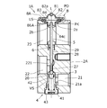
- FIG. 1 is a schematic cross-sectional view schematically showing an example in which the expansion valve 1 in the present embodiment is applied to the refrigerant circulation system 100.
- the expansion valve 1 is fluidly connected to the compressor 101, the condenser 102, and the evaporator 104.
- L be the axis of the expansion valve 1.
- the expansion valve 1 includes a valve body 2 having a valve chamber VS, a valve body 3, an urging device 4, an operating rod 5, and a power element 8.
- the valve body 2 includes a first flow path 21, a second flow path 22, an intermediate chamber 221 and a return flow path (also referred to as a refrigerant passage) 23 in addition to the valve chamber VS.
- the first flow path 21 is a supply-side flow path, and the refrigerant is supplied to the valve chamber VS via the supply-side flow path.
- the second flow path 22 is a discharge side flow path, and the fluid in the valve chamber VS is discharged to the outside of the expansion valve through the valve through hole 27, the intermediate chamber 221 and the discharge side flow path.
- the first flow path 21 and the valve chamber VS communicate with each other by a connecting path 21a having a smaller diameter than the first flow path 21.
- the valve chamber VS and the intermediate chamber 221 communicate with each other via a valve seat 20 and a valve through hole 27.
- the actuating rod insertion hole 28 formed above the intermediate chamber 221 has a function of guiding the actuating rod 5, and the annular recess 29 formed above the actuating rod insertion hole 28 has a function of accommodating the ring spring 6.
- the ring spring 6 abuts a plurality of spring pieces on the outer circumference of the operating rod 5 to apply a predetermined urging force.
- the valve body 3 is arranged in the valve chamber VS.
- the valve body 3 When the valve body 3 is seated on the valve seat 20 of the valve body 2, the flow of the refrigerant in the valve through hole 27 is restricted. This state is called a non-communication state. However, even when the valve body 3 is seated on the valve seat 20, a limited amount of refrigerant may flow. On the other hand, when the valve body 3 is separated from the valve seat 20, the flow of the refrigerant passing through the valve through hole 27 increases. This state is called a communication state.
- the operating rod 5 is inserted into the valve through hole 27 with a predetermined gap.
- the lower end of the operating rod 5 is in contact with the upper surface of the valve body 3.
- the upper end of the operating rod 5 is fitted in the fitting hole 84c of the stopper member 84, which will be described later.
- the operating rod 5 can press the valve body 3 in the valve opening direction against the urging force of the urging device 4. When the operating rod 5 moves downward, the valve body 3 is separated from the valve seat 20 and the expansion valve 1 is opened.
- the urging device 4 has a coil spring 41 in which a wire rod having a circular cross section is spirally wound, a valve body support 42, and a spring receiving member 43.
- valve body support 42 is attached to the upper end of the coil spring 41, and a spherical valve body 3 is welded to the upper surface thereof, and both are integrated.
- the spring receiving member 43 that supports the lower end of the coil spring 41 is screwable with respect to the valve body 2, and has a function of sealing the valve chamber VS and a function of adjusting the urging force of the coil spring 41. ..
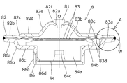
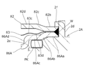
- FIG. 2 is an enlarged cross-sectional view of the power element 8.
- the power element 8 has a stopper 81, an upper lid member 82, a diaphragm 83, a receiving member 86, and a stopper member 84.
- the upper lid member 82 side is the upper side and the receiving member 86 side is the lower side.
- the upper lid member 82 is formed, for example, by molding a metal plate material by pressing.
- the upper lid member 82 has an annular outer plate portion 82b, an outer tapered portion 82c connected to the inner circumference of the outer plate portion 82b and facing upward, and an annular intermediate plate portion connected to the inner circumference of the outer tapered portion 82c. It has an 82d, an inner tapered portion 82e connected to the inner circumference of the intermediate plate portion 82d and directed upward, and a top portion 82f connected to the inner circumference of the inner tapered portion 82e.
- An opening 82a is formed in the center of the top portion 82f, and can be sealed by a stopper 81.
- the receiving member 86 facing the upper lid member 82 is formed, for example, by molding a metal plate material by pressing.
- the receiving member 86 includes a flange portion 86a having an outer diameter substantially the same as the outer diameter of the outer plate portion 82b of the upper lid member 82, a conical portion 86b connected to the inner circumference of the flange portion 86a and facing downward, and a conical portion 86b. It has an annular inner plate portion 86c connected to the inner circumference of the inner circumference and a hollow cylindrical portion 86d connected to the inner circumference of the inner plate portion 86c.
- a male screw 86e is formed on the outer circumference of the hollow cylindrical portion 86d.
- a female screw 2c screwed into the male screw 86e is formed on the inner circumference of the recess 2a of the valve body 2 to which the hollow cylindrical portion 86d is attached.
- the diaphragm 83 arranged between the upper lid member 82 and the receiving member 86 is made of a thin and flexible metal (for example, SUS) plate material, and has the outer diameter of the upper lid member 82 and the receiving member 86. It has almost the same outer diameter.
- the diaphragm 83 has an outer peripheral portion 83a sandwiched between the upper lid member 82 and the receiving member 86, and a central portion 83b that abuts on the stopper member 84. Further, the diaphragm 83 is coaxial with the axis O between the outer peripheral portion 83a and the central portion 83b, and has a plurality of upper ring-shaped portions 83c protruding upward and a plurality of lower ring-shaped portions protruding downward. Parts 83d are provided alternately along the radial direction. In the present embodiment, in the cross section shown in FIG.
- the upper ring-shaped portion 83c and the lower ring-shaped portion 83d have a periodic shape such that a substantially sine curve is drawn, but the peripheral groove-shaped upper ring-shaped portion having a semicircular cross section.
- the lower ring-shaped portion may be formed independently on the flat plate.
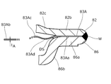
- FIG. 3 is an enlarged cross-sectional view showing part A of FIG. 2 in the present embodiment.
- the outer peripheral portion 83a is sandwiched between the outer plate portion 82b of the upper lid member 82 and the flange portion 86a of the receiving member 86 to hold the diaphragm 83.
- the outer peripheral ends of the outer plate portion 82b, the outer peripheral portion 83a, and the flange portion 86a are welded and joined as described later.
- the lower ring-shaped portion 83d closest to the outer circumference of the diaphragm 83 is arranged closer to the outer circumference than the upper ring-shaped portion 83c closest to the outer circumference of the diaphragm 83, and a gap is provided between the lower ring-shaped portion 83d and the receiving member 86. Is formed.
- the plate thickness of the outer peripheral portion 83a is thicker than the plate thickness of the central portion 83b of the diaphragm 83. More specifically, from the central portion 83b to the apex P1 of the lower ring-shaped portion 83d closest to the outer circumference, the plate thickness t of the diaphragm 83 is substantially constant, but the apex P1 of the lower ring-shaped portion 83d closest to the outer circumference. The plate thickness t gradually increases from the contact point P3 of the outer peripheral portion 83a that first contacts the upper lid member 82. The plate thickness t of the outer peripheral portion 83a is constant on the outer peripheral side of the contact P3. The contact point P3 is near the fulcrum of the diaphragm 83.
- the stopper member 84 is fitted with a cylindrical main body 84a, a disk portion 84b connected to the upper end of the main body 84a and extending in the radial direction, and a bag hole shape formed in the center of the lower surface of the main body 84a. It has a hole 84c.
- the disk portion 84b is in contact with the lower surface of the central portion 83b of the diaphragm 83.
- the procedure for assembling the power element 8 will be described. While arranging the stopper member 84 between the diaphragm 83 and the receiving member 86, the outer plate portion 82b of the upper lid member 82, the outer peripheral portion 83a of the diaphragm 83, and the flange portion 86a of the receiving member 86 are overlapped in this order. While pressing in the direction, the outer periphery thereof is welded by, for example, TIG welding, laser welding, plasma welding, etc. to form a welded portion W over the entire circumference, and these are integrated.
- the working gas is sealed in the space (referred to as the pressure working chamber PO) surrounded by the upper lid member 82 and the diaphragm 83 from the opening 82a formed in the upper lid member 82, and then the opening 82a is sealed with the stopper 81. Further, the stopper 81 is fixed to the upper lid member 82 by projection welding or the like.
- the diaphragm 83 receives pressure in a form of projecting toward the receiving member 86 due to the working gas sealed in the pressure operating chamber PO, the lower space (refrigerant inflow chamber) surrounded by the diaphragm 83 and the receiving member 86.
- the central portion 83b of the diaphragm 83 abuts and is supported on the upper surface of the stopper member 84 arranged in the LS.
- the axis O is aligned with the axis L, and the male screw 86e on the outer periphery of the lower end of the hollow cylindrical portion 86d of the receiving member 86 is attached to the valve body. It is screwed into the female screw 2c formed on the inner circumference of the recess 2a of 2.
- the male screw 86e of the hollow cylindrical portion 86d is screwed with respect to the female screw 2c, the inner plate portion 86c of the receiving member 86 comes into contact with the upper end surface of the valve body 2. As a result, the power element 8 can be fixed to the valve body 2.
- a packing PK is interposed between the power element 8 and the valve body 2 to seal the space in the recess 2a connected to the lower space LS to prevent the refrigerant from leaking from the recess 2a.
- the lower space LS of the power element 8 communicates with the return flow path 23 via the communication hole 2b.
- the refrigerant pressurized by the compressor 101 is liquefied by the condenser 102 and sent to the expansion valve 1. Further, the refrigerant adiabatically expanded by the expansion valve 1 is sent to the evaporator 104, and the evaporator 104 exchanges heat with the air flowing around the evaporator. The refrigerant returning from the evaporator 104 is returned to the compressor 101 side through the expansion valve 1 (more specifically, the return flow path 23). At this time, by passing through the evaporator 104, the fluid pressure in the second flow path 22 becomes larger than the fluid pressure in the return flow path 23.
- High-pressure refrigerant is supplied to the expansion valve 1 from the condenser 102. More specifically, the high-pressure refrigerant from the condenser 102 is supplied to the valve chamber VS via the first flow path 21.
- valve body 3 When the valve body 3 is seated on the valve seat 20 (in a non-communication state), it is sent from the valve chamber VS to the evaporator 104 through the valve passage hole 27, the intermediate chamber 221 and the second flow path 22. The flow rate of the refrigerant is limited. On the other hand, when the valve body 3 is separated from the valve seat 20 (in the state of communication), the valve chamber VS passes through the valve passage hole 27, the intermediate chamber 221 and the second flow path 22 to the evaporator 104. The flow rate of the delivered refrigerant increases. Switching between the closed state and the open state of the expansion valve 1 is performed by the operating rod 5 connected to the power element 8 via the stopper member 84.
- a pressure operating chamber PO and a lower space LS partitioned by a diaphragm 83 are provided inside the power element 8. Therefore, when the working gas in the pressure working chamber PO is liquefied, the diaphragm 83 rises (shown by the dotted line in FIG. 2), so that the stopper member 84 and the working rod 5 move up according to the urging force of the coil spring 41. Move in the direction. On the other hand, when the liquefied working gas is vaporized, the diaphragm 83 and the stopper member 84 are pressed downward (shown by a solid line in FIG. 2), so that the working rod 5 moves downward. In this way, the expansion valve 1 is switched between the open state and the closed state.
- the lower space LS of the power element 8 communicates with the return flow path 23. Therefore, the volume of the working gas in the pressure working chamber PO changes according to the temperature and pressure of the refrigerant flowing through the return flow path 23, and the working rod 5 is driven.
- the amount of the refrigerant supplied from the expansion valve 1 toward the evaporator 104 is automatically adjusted according to the temperature and pressure of the refrigerant returning from the evaporator 104 to the expansion valve 1. It will be adjusted.
- FIG. 4 is an enlarged view showing a portion of the power element 8A according to the comparative example corresponding to the portion A of FIG.
- the power element 8A according to the comparative example has an outer peripheral portion 83Aa and a central portion 83Ab as in the present embodiment, and also has a plurality of upper ring-shaped portions 83Ac and a plurality of lower ring-shaped portions 83Ad, but the plate thickness is t. It differs from the present embodiment in that A is constant. Since the configurations of the upper lid member 82, the receiving member 86, and the stopper member 84 are the same as those in the present embodiment, the same reference numerals are given and duplicate description will be omitted.
- foreign matter DS such as metal powder mixed in the refrigerant may enter the lower space LS via the return flow path 23.
- the foreign matter DS may enter the gap between the diaphragm 83A and the receiving member 86, and the foreign matter DS may be caught between the diaphragm 83A and the receiving member 86 according to the downward displacement of the diaphragm 83A. .. Since the diaphragm 83A is formed of a very thin metal plate, when a relatively hard foreign matter DS is bitten, stress concentration occurs and causes local deformation, etc., and in some cases, the operating characteristics of the power element 8A deteriorate. There is a risk of causing it.
- the power element 8 of the present embodiment referring to FIG. 3, from the apex of the lower ring-shaped portion 83d closest to the outer circumference of the diaphragm 83 to the outer peripheral side, particularly at a position where foreign matter DS is bitten. Since the plate thickness t is increased, local deformation of the diaphragm 83 can be suppressed. As a result, a normal strainer (not shown) used in the refrigeration circulation system 100 can be used, and the efficiency of transporting the refrigerant is not lowered.
- the diaphragm 83 of the present embodiment is different from the diaphragm 83A of the comparative example. Similarly, it is easily bent, and therefore, the operating characteristics of the power element 8 are not deteriorated even when compared with the power element 8A of the comparative example.
- the plate thickness of the diaphragm 83 In order to suppress local deformation of the power element due to foreign matter biting, it is not always necessary to increase the plate thickness of the diaphragm 83 radially outward from the apex of the lower ring-shaped portion 83d closest to the outer circumference. For example, it is sufficient to increase the plate thickness in the vicinity of the fulcrum of the diaphragm 83, where foreign matter is likely to be caught.
- the "fulcrum” includes a fulcrum on the upper lid member side and a fulcrum on the receiving member side.
- the “fulcrum on the upper lid member side” refers to a portion where the diaphragm is stopped by contacting the upper lid member (not displaced toward the upper lid member side) and a portion displaced toward the upper lid member side when the diaphragm is flexed and displaced. Refers to the point of the upper lid member in contact with the boundary point of. In the example shown in FIG. 3, the point P3 serves as a fulcrum on the upper lid member 82 side.
- the "fulcrum on the receiving member side” means a portion where the diaphragm is stopped (not displaced toward the receiving member side) by abutting against the receiving member when the diaphragm is bent and displaced, and is displaced toward the receiving member side.
- “near the fulcrum” is preferably in the range of ⁇ 0.1R in the radial direction about the fulcrum, more preferably in the range of ⁇ 0.05R, where R is the radius of the diaphragm.
- the plate thickness of the outer portion of the diaphragm is preferably thicker than the plate thickness of the central portion, and more preferably 1.3 times or more the plate thickness of the central portion.
- FIG. 5 is a schematic cross-sectional view showing the expansion valve 1A in the second embodiment.
- FIG. 6 is a cross-sectional view of the power element 8A in the second embodiment.
- FIG. 7 is an enlarged cross-sectional view showing a portion B of FIG. 5 in the second embodiment.
- the expansion valve 1A shown in FIG. 5 differs from the expansion valve 1 according to the first embodiment in the upper configuration of the power element 8A and the valve body 2A. That is, in the present embodiment, the power element 8A and the valve body 2A are not connected by screwing the screws, and the two are connected by caulking. Since the other configurations are the same as those in the first embodiment, the same reference numerals are given and duplicate description will be omitted.
- the power element 8A has a stopper 81, an upper lid member 82, a diaphragm 83, a receiving member 86A, and a stopper member 84.
- the upper lid member 82A side is the upper side and the receiving member 86A side is the lower side.
- the stopper member may not be provided.
- the configuration of the receiving member 86A is mainly different from that of the power element 8 in the first embodiment. Since the other stopper 81, the upper lid member 82, the diaphragm 83, and the stopper member 84 have basically the same configuration except that the shapes of the details are different, the same reference numerals are given and duplicate description will be omitted.
- the receiving member 86A formed by molding a metal plate material by pressing is connected to the flange portion 86Aa having an outer diameter substantially the same as the outer diameter of the outer plate portion 82b of the upper lid member 82 and the inner circumference of the flange portion 86Aa.
- the inner plate portion 86Ae includes a central opening 86Af into which the main body 84a of the stopper member 84 is fitted.
- the outer periphery thereof is welded by, for example, TIG welding, laser welding, plasma welding, etc. to form a welded portion W over the entire circumference, and these are integrated.
- the working gas is sealed in the space surrounded by the upper lid member 82 and the diaphragm 83, the opening 82a is sealed with the stopper 81, and further projection welding or the like is used.
- the stopper 81 is fixed to the upper lid member 82. As described above, the power element 8A is assembled.
- valve body 2A formed of a metal such as aluminum includes a circular tube portion 2d extending from the upper end thereof.
- the inner diameter of the circular tube portion 2d is equal to or slightly larger than the outer diameter of the power element 8A.
- the circular tube portion 2d Before assembling the power element 8A to the valve body 2A, the circular tube portion 2d has a cylindrical shape centered on the axis L (FIG. 5) as shown by the dotted line.
- an annular packing PK is arranged on the step portion 2e of the valve body 2A, approaches the valve body 2A from the receiving member 86A side, and the power element 8A is inside the circular tube portion 2d. To fit. At this time, the packing PK is sandwiched between the intermediate plate portion 86Ac and the step portion 2e.
- the expansion valve 1A shown in FIG. 5 can also be incorporated into the refrigerant circulation system 100 shown in FIG. 1, and exhibits the same function as the expansion valve 1 according to the first embodiment.
- the present invention is not limited to the above-described embodiment.
- any component of the above-described embodiment can be modified.
- any component can be added or omitted in the above-described embodiment.
- Valve body 3 Valve body 4: Evaporating device 5: Actuating rod 6: Ring spring 8, 8A: Power element 20: Valve seat 21: First flow path 22: Second flow Road 221: Intermediate chamber 23: Return flow path 27: Valve through hole 28: Actuating rod insertion hole 29: Annulus recess 41: Coil spring 42: Valve body support 43: Spring receiving member 81: Plug 82: Upper lid member 83: Diaphragm 84 : Stopper members 86, 86A: Receiving member 100: Refrigerant circulation system 101: Compressor 102: Capacitor 104: Evaporator VS: Valve chamber P1: Lower ring-shaped apex P3: Contact
Landscapes
- Engineering & Computer Science (AREA)
- General Engineering & Computer Science (AREA)
- Mechanical Engineering (AREA)
- Physics & Mathematics (AREA)
- Fluid Mechanics (AREA)
- Thermal Sciences (AREA)
- Temperature-Responsive Valves (AREA)
Priority Applications (3)
| Application Number | Priority Date | Filing Date | Title |
|---|---|---|---|
| US17/778,955 US12061025B2 (en) | 2019-11-25 | 2020-11-25 | Power element and expansion valve using same |
| EP20892779.8A EP4067713A4 (en) | 2019-11-25 | 2020-11-25 | THERMOSTATIC TRAIN AND REGULATOR USING IT |
| CN202080076623.0A CN114667422B (zh) | 2019-11-25 | 2020-11-25 | 动力元件以及使用了该动力元件的膨胀阀 |
Applications Claiming Priority (2)
| Application Number | Priority Date | Filing Date | Title |
|---|---|---|---|
| JP2019212451A JP7366401B2 (ja) | 2019-11-25 | 2019-11-25 | パワーエレメント及びこれを用いた膨張弁 |
| JP2019-212451 | 2019-11-25 |
Publications (1)
| Publication Number | Publication Date |
|---|---|
| WO2021106932A1 true WO2021106932A1 (ja) | 2021-06-03 |
Family
ID=76087275
Family Applications (1)
| Application Number | Title | Priority Date | Filing Date |
|---|---|---|---|
| PCT/JP2020/043821 Ceased WO2021106932A1 (ja) | 2019-11-25 | 2020-11-25 | パワーエレメント及びこれを用いた膨張弁 |
Country Status (5)
| Country | Link |
|---|---|
| US (1) | US12061025B2 (enExample) |
| EP (1) | EP4067713A4 (enExample) |
| JP (1) | JP7366401B2 (enExample) |
| CN (1) | CN114667422B (enExample) |
| WO (1) | WO2021106932A1 (enExample) |
Families Citing this family (2)
| Publication number | Priority date | Publication date | Assignee | Title |
|---|---|---|---|---|
| JP7510138B2 (ja) * | 2020-12-24 | 2024-07-03 | 株式会社不二工機 | 差圧弁およびそれを有する弁装置 |
| US12460844B2 (en) * | 2021-12-08 | 2025-11-04 | Parker-Hannifin Corporation | Ball seal for thermal sensor assembly of thermostatic expansion valve |
Citations (3)
| Publication number | Priority date | Publication date | Assignee | Title |
|---|---|---|---|---|
| JPH07133972A (ja) * | 1993-11-09 | 1995-05-23 | Saginomiya Seisakusho Inc | 膨張弁 |
| JP2005090524A (ja) * | 2003-09-12 | 2005-04-07 | Tgk Co Ltd | 大気開放弁 |
| JP2019163896A (ja) | 2018-03-20 | 2019-09-26 | 株式会社不二工機 | パワーエレメントおよびそれを有する膨張弁 |
Family Cites Families (6)
| Publication number | Priority date | Publication date | Assignee | Title |
|---|---|---|---|---|
| US9212720B2 (en) * | 2010-05-19 | 2015-12-15 | Yamashita Rubber Kabushiki Kaisha | Liquid sealed vibration isolating device |
| JP5634224B2 (ja) * | 2010-11-05 | 2014-12-03 | 株式会社クボタ | フィルタプレス脱水装置 |
| JP5730629B2 (ja) * | 2011-03-22 | 2015-06-10 | 株式会社不二工機 | 膨張弁 |
| JP6593120B2 (ja) * | 2014-12-18 | 2019-10-23 | 株式会社デンソー | ダイヤフラムを備える装置およびエジェクタ |
| KR101774166B1 (ko) * | 2016-08-08 | 2017-09-01 | 주식회사 락앤락 | 식품 용기 |
| CN109900024B (zh) * | 2017-12-11 | 2022-04-05 | 浙江三花汽车零部件有限公司 | 热力膨胀阀 |
-
2019
- 2019-11-25 JP JP2019212451A patent/JP7366401B2/ja active Active
-
2020
- 2020-11-25 WO PCT/JP2020/043821 patent/WO2021106932A1/ja not_active Ceased
- 2020-11-25 US US17/778,955 patent/US12061025B2/en active Active
- 2020-11-25 EP EP20892779.8A patent/EP4067713A4/en active Pending
- 2020-11-25 CN CN202080076623.0A patent/CN114667422B/zh active Active
Patent Citations (3)
| Publication number | Priority date | Publication date | Assignee | Title |
|---|---|---|---|---|
| JPH07133972A (ja) * | 1993-11-09 | 1995-05-23 | Saginomiya Seisakusho Inc | 膨張弁 |
| JP2005090524A (ja) * | 2003-09-12 | 2005-04-07 | Tgk Co Ltd | 大気開放弁 |
| JP2019163896A (ja) | 2018-03-20 | 2019-09-26 | 株式会社不二工機 | パワーエレメントおよびそれを有する膨張弁 |
Non-Patent Citations (1)
| Title |
|---|
| See also references of EP4067713A4 |
Also Published As
| Publication number | Publication date |
|---|---|
| EP4067713A4 (en) | 2023-11-22 |
| EP4067713A1 (en) | 2022-10-05 |
| CN114667422A (zh) | 2022-06-24 |
| CN114667422B (zh) | 2024-04-12 |
| JP2021085546A (ja) | 2021-06-03 |
| US12061025B2 (en) | 2024-08-13 |
| JP7366401B2 (ja) | 2023-10-23 |
| US20220412616A1 (en) | 2022-12-29 |
Similar Documents
| Publication | Publication Date | Title |
|---|---|---|
| JP5905456B2 (ja) | 溶接されたダイヤフラムのための締付リング | |
| WO2021106933A1 (ja) | パワーエレメント及びこれを用いた膨張弁 | |
| JP7624762B2 (ja) | パワーエレメント及びこれを用いた膨張弁 | |
| WO2021106932A1 (ja) | パワーエレメント及びこれを用いた膨張弁 | |
| WO2020189092A1 (ja) | 膨張弁 | |
| JP7390699B2 (ja) | 膨張弁 | |
| JP7217504B2 (ja) | 膨張弁 | |
| JP7165972B2 (ja) | 膨張弁 | |
| JP7373857B2 (ja) | パワーエレメント及びそれを用いた膨張弁 | |
| JP7357338B2 (ja) | パワーエレメント及びこれを用いた膨張弁 | |
| JP7519664B2 (ja) | 膨張弁 | |
| JP7349706B2 (ja) | パワーエレメント及びこれを用いた膨張弁 | |
| JP2025011916A (ja) | 膨張弁 | |
| JP7246075B2 (ja) | 膨張弁 | |
| JP7266283B2 (ja) | 弁装置 | |
| JP2024113354A (ja) | 膨張弁 | |
| JP2022021827A (ja) | 膨張弁 | |
| JP2024068727A (ja) | 膨張弁 | |
| JP2022184379A (ja) | 膨張弁 | |
| JP2022163447A (ja) | 膨張弁 |
Legal Events
| Date | Code | Title | Description |
|---|---|---|---|
| 121 | Ep: the epo has been informed by wipo that ep was designated in this application |
Ref document number: 20892779 Country of ref document: EP Kind code of ref document: A1 |
|
| NENP | Non-entry into the national phase |
Ref country code: DE |
|
| ENP | Entry into the national phase |
Ref document number: 2020892779 Country of ref document: EP Effective date: 20220627 |