WO2021106900A1 - 内固定部材セットおよび内固定部材 - Google Patents
内固定部材セットおよび内固定部材 Download PDFInfo
- Publication number
- WO2021106900A1 WO2021106900A1 PCT/JP2020/043732 JP2020043732W WO2021106900A1 WO 2021106900 A1 WO2021106900 A1 WO 2021106900A1 JP 2020043732 W JP2020043732 W JP 2020043732W WO 2021106900 A1 WO2021106900 A1 WO 2021106900A1
- Authority
- WO
- WIPO (PCT)
- Prior art keywords
- head
- fixing member
- internal fixing
- screw
- outer member
- Prior art date
- Legal status (The legal status is an assumption and is not a legal conclusion. Google has not performed a legal analysis and makes no representation as to the accuracy of the status listed.)
- Ceased
Links
Images


Classifications
-
- A—HUMAN NECESSITIES
- A61—MEDICAL OR VETERINARY SCIENCE; HYGIENE
- A61B—DIAGNOSIS; SURGERY; IDENTIFICATION
- A61B17/00—Surgical instruments, devices or methods
- A61B17/56—Surgical instruments or methods for treatment of bones or joints; Devices specially adapted therefor
- A61B17/58—Surgical instruments or methods for treatment of bones or joints; Devices specially adapted therefor for osteosynthesis, e.g. bone plates, screws or setting implements
- A61B17/68—Internal fixation devices, including fasteners and spinal fixators, even if a part thereof projects from the skin
- A61B17/70—Spinal positioners or stabilisers, e.g. stabilisers comprising fluid filler in an implant
- A61B17/7001—Screws or hooks combined with longitudinal elements which do not contact vertebrae
- A61B17/7035—Screws or hooks, wherein a rod-clamping part and a bone-anchoring part can pivot relative to each other
- A61B17/7037—Screws or hooks, wherein a rod-clamping part and a bone-anchoring part can pivot relative to each other wherein pivoting is blocked when the rod is clamped
-
- A—HUMAN NECESSITIES
- A61—MEDICAL OR VETERINARY SCIENCE; HYGIENE
- A61B—DIAGNOSIS; SURGERY; IDENTIFICATION
- A61B17/00—Surgical instruments, devices or methods
- A61B17/56—Surgical instruments or methods for treatment of bones or joints; Devices specially adapted therefor
- A61B17/58—Surgical instruments or methods for treatment of bones or joints; Devices specially adapted therefor for osteosynthesis, e.g. bone plates, screws or setting implements
- A61B17/68—Internal fixation devices, including fasteners and spinal fixators, even if a part thereof projects from the skin
- A61B17/70—Spinal positioners or stabilisers, e.g. stabilisers comprising fluid filler in an implant
- A61B17/7001—Screws or hooks combined with longitudinal elements which do not contact vertebrae
- A61B17/7032—Screws or hooks with U-shaped head or back through which longitudinal rods pass
Definitions
- the present disclosure relates to an internal fixing member set and an internal fixing member.
- the facet coupling device includes a movable element, an intermediate element, a fixing element, and a screw for preventing disconnection.
- the intermediate element is rotatably housed inside the movable element.
- the fixation element is a screw that is attached to the vertebrae, the head of which is rotatably housed inside the intermediate element.
- the captive screw is detachably attached to the fixing element on the outside of the movable element to prevent the fixing element from coming off the intermediate element.
- the internal fixation member set includes an internal fixation member, an outer member, and an inner member.
- the internal fixing member includes an internal fixing member main body that can be installed on a bone and a spherical head arranged at one end of the internal fixing member main body.
- the outer member has a tubular shape having a first opening and a second opening, and holds the head rotatably.
- the inner member is located inside the outer member on the first opening side of the head, and can be moved between the first position away from the head and the second position on the second opening side of the first position. Be arranged.
- the inner member has a first interference portion capable of interfering with the head.
- the head has a second interference portion capable of interfering with the first interference portion of the inner member.
- the second rotation range of the head when the inner member is located at the second position is larger than the first rotation range of the head when the inner member is located at the first position due to the interference of the first interference portion and the second interference portion. Is also small.
- the reference rotation position where the head can be inserted and removed from the outer member is included in the first rotation range, and is not included in the second rotation range.
- the internal fixation member is an outer member having a tubular shape having a first opening and a second opening, and an inner member that can move between a first position and a second position inside the outer member.
- the internal fixing member includes an internal fixing member main body and a head.
- the internal fixation member main body includes an internal fixation member main body that can be installed on the bone and a spherical head that is connected to one end of the internal fixation member main body and is held inside the outer member on the second opening side of the inner member. Be prepared.
- the inner member has a first interference portion capable of interfering with the head.
- the head has a second interference portion capable of interfering with the first interference portion of the inner member.
- the second rotation range of the head in the state where the inner member is located in the second position is larger than the first rotation range of the head in the state where the inner member is in the first position. Is also small.
- the first rotation range includes the reference rotation position, and the second rotation range does not include the reference rotation position.
- the present disclosure provides an internal fixation member set and an internal fixation member capable of assembling each element of the bone internal fixation member set with a simple operation and making it difficult to separate them.
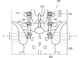
- FIG. 1 is a diagram schematically showing an example of the configuration of an implant 100 for a living body.
- the implant 100 is an implant for the human spine.
- Implant 100 fixes a plurality of lumbar vertebrae 210, sacrum 220 and ilium 230 in the body to each other.
- the implant 100 includes a screw assembly 110, a screw assembly 1 and a rod 130. These are composed of biocompatible materials.
- the material includes, for example, at least one of titanium, titanium alloys, cobalt-chromium alloys and stainless steel.
- each screw assembly 1 penetrates the sacroiliac joint with the sacral wing of the second sacrum of the sacrum 220 as an entrance and is implanted in the ilium 230 just above the ischial notch.
- the screw assembly 110 and the screw assembly 1 located on the right side are connected to each other by one rod 130.
- the rod 130 has a cylindrical shape.
- the screw assembly 110 and the screw assembly 1 located on the left side are connected to each other by another rod 130.
- Each screw assembly 110 includes a screw 111, a coupling member 112, and a fastening member 113.
- the coupling member 112 has a tubular shape, and the head of the screw 111 is arranged inside the coupling member 112.
- the screw 111 extends laterally from the coupling member 112 and is implanted in the lumbar spine 210.
- the head of the screw 111 is rotatable with respect to the coupling member 112. Therefore, the posture of the connecting member 112 can be adjusted while the screw 111 is embedded in the lumbar vertebra 210.
- a part of the rod 130 in the longitudinal direction can be inserted into the coupling member 112, and the part of the rod 130 in the longitudinal direction is sandwiched from the side in the inserted state.
- the posture of the coupling member 112 is adjusted so that the rod 130 can be inserted with the screw 111 embedded in the lumbar vertebra 210.
- the fastening member 113 is, for example, a bolt and is fastened to the coupling member 112. By this fastening, the rod 130 is fixed in the coupling member 112.
- the screw assembly 1 also includes a screw 2, a connecting member 3, and a fastening member 7.
- the coupling member 3 has a tubular shape, and the head 22 of the screw 2 is rotatably arranged inside the coupling member 3.
- the screw 2 extends outward from the coupling member 3.
- the screw 2 is implanted in the sacrum 220 and the ilium 230.
- the sacrum 220 and the ilium 230 are collectively referred to as a target bone. Since the head 22 of the screw 2 is rotatable with respect to the connecting member 3, the posture of the connecting member 3 can be adjusted while the screw 2 is embedded in the target bone.
- a part of the rod 130 in the longitudinal direction can be inserted into the coupling member 3, and the part of the rod 130 in the longitudinal direction is sandwiched from the side in the inserted state.
- the posture of the connecting member 3 is adjusted so that the rod 130 can be inserted into the connecting member 3 with the screw 2 embedded in the target bone.
- the fastening member 7 is, for example, a bolt, and is fastened to the coupling member 3 to fix the rod 130.
- the screw assembly 110 is embedded in the lumbar vertebra 210, and the screw assembly 1 is embedded in the sacrum 220 and the ilium 230. Then, the screw assembly 110 and the screw assembly 1 are connected to each other by the rod 130. Therefore, the lumbar vertebra 210, the sacrum 220, and the ilium 230 can be fixed to each other.
- the screw 2 extends laterally.
- the screw 2 of the screw assembly 1 located on the right side extends to the right side
- the screw assembly 1 located on the left side extends to the left side. That is, unlike the screw assembly 110, the rotation range of the screw 2 with respect to the connecting member 3 does not have to be isotropic and may be wide on one side with respect to the connecting member 3.
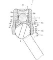
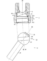
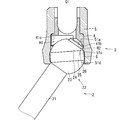
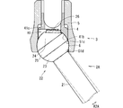
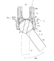
- FIG. 2 is a sectional view schematically showing an example of the configuration of the screw assembly 1
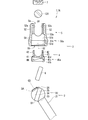
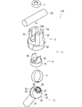
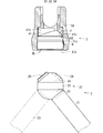
- FIG. 3 is an exploded sectional view schematically showing an example of the configuration of the screw assembly 1
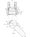
- FIG. 4 is an exploded sectional view schematically showing an example of the configuration of the screw assembly 1. It is an exploded perspective view which shows an example of the structure of.
- the screw assembly 1 includes a screw 2, a coupling member 3, and a fastening member 7, which are examples of internal fixing members.
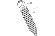
- the screw 2 is a member to be embedded in the target bone.
- the connecting member 3 is a member that connects the screw 2 and the rod 130, and includes an inner member 4 and an outer member 5.
- the screw assembly 1 includes a screw 2, an inner member 4, an outer member 5, and a fastening member 7 as parts, and is configured by assembling these. These pre-assembled states are also referred to as screw set 1A (internal fixation member set). In FIGS. 3 and 4, since they are separated, it can be grasped that the screw set 1A is shown. In the following, each configuration will be outlined first and then detailed.
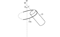
- the screw 2 includes a screw body 21 which is an example of an internal fixing member body and a head 22.
- the screw body 21 has an elongated shape.
- the screw body 21 is embedded in the target bone from the tip side.
- the head 22 has a substantially spherical shape and is connected to the other end (also referred to as a base end) of the screw body 21.
- the outer member 5 has a substantially tubular shape having a first opening 5a and a second opening 5b. Specifically, the outer member 5 has a substantially cylindrical shape centered on the virtual central axis Q1.
- the outer member 5 rotatably holds the head 22 of the screw 2.
- a spherical concave surface 51c along the virtual spherical surface B1 of the head 22 is formed on the inner peripheral surface of the outer member 5, and the head 22 fits into the spherical concave surface 51c.
- the head 22 is fixed inside the outer member 5 by the fastening member 7 as described later, the head 22 is rotatable inside the outer member 5 at least before fastening.
- a high-strength cobalt-chromium alloy can be used as the material of the outer member 5.
- the second opening 5b side is referred to as the lower side
- the first opening 5a side is referred to as the upper side
- the upper side and the lower side referred to here have nothing to do with the vertical direction and are set with respect to the shape of the outer member 5.
- the second opening 5b is also referred to as a lower opening 5b
- the first opening 5a is also referred to as an upper opening 5a.
- the screw body 21 of the screw 2 extends from the head 22 to the outside of the outer member 5 below the outer member 5. Since the head 22 is rotatable with respect to the outer member 5, the screw 2 can swing around the head 22 with respect to the coupling member 3.
- the swing motion referred to here means that the tip of the screw body 21 moves along the virtual spherical surface around the head 22. That is, the inclination angle of the screw body 21 with respect to the outer member 5 is variable.
- the inner member 4 is housed inside the outer member 5 and is located above the head 22.
- the inner member 4 presses the head 22 downward by the fastening member 7 as described later.
- the head 22 is sandwiched by the inner member 4 and the lower portion of the spherical concave surface 51c.
- the rotation position of the head 22 is fixed.
- the inner member 4 comes into contact with the interference portion 26 (described later) of the head 22 to limit the rotation range of the head 22. This point will be described in detail later.
- a part of the rod 130 in the longitudinal direction is inserted into the outer member 5 from the upper opening 5a thereof.
- the fastening member 7 is inserted into the upper opening 5a of the outer member 5.
- the fastening member 7 is a bolt such as a hexagon socket head cap screw, and is screwed onto the inner peripheral surface of the upper end portion of the outer member 5.
- the tip of the fastening member 7 abuts on the rod 130 and presses the rod 130 downward.
- the rod 130 presses the inner member 4 downward, and the inner member 4 presses the head 22 downward.
- the rod 130 and the head 22 are fixed inside the outer member 5.
- the screw body 21 has a substantially cylindrical shape centered on the virtual central axis Q3, and a screw thread (not shown) is formed on the outer peripheral surface thereof. The thread is spirally formed from the tip of the screw body 21 toward the other end.
- the screw body 21 is embedded in the target bone as described above.
- the screw 2 embedded in the sacrum 220 and the ilium 230 is also referred to as an S2AI screw.
- the screw body 21 is also called a shaft portion of the screw 2.
- the head 22 is connected to one end of the screw body 21.
- the screw body 21 and the head 22 may be made of the same material and integrally formed with each other.
- the head 22 has a substantially spherical shape.
- the head 22 is located on the virtual center axis Q3, and as a more specific example, the center of the head 22 may be located on the virtual center axis Q3.
- the head 22 includes a pair of partial spherical portions 23, 24, a flat band portion 25, and an interference portion 26.
- the pair of partial spherical surfaces 23 and 24 have a shape along the virtual spherical surface B1.
- the diameter of the virtual spherical surface B1 is larger than the diameter of the screw body 21.
- the partial spherical portion 23 is connected to one end of the screw body 21.
- the flat band portion 25 is a band-shaped flat surface formed along the entire circumference of the great circle of the head 22.
- the great circle here is a circle where the virtual sphere B1 intersects the plane passing through its center.
- the flat band portion 25 has a substantially cylindrical shape centered on a virtual central axis Q4 passing through the center of the virtual spherical surface B1.
- the virtual central axis Q4 intersects the virtual central axis Q3. That is, the flat band portion 25 is inclined with respect to the virtual central axis Q3 on which the screw body 21 extends.
- the flat band portion 25 is located between the partial spherical portions 23 and 24 and is connected to these.
- the diameter of the flat band portion 25 is smaller than the diameter of the virtual spherical surface B1 along which the partial spherical surfaces 23 and 24 are aligned. As will be described later, the flat band portion 25 is used when the head 22 is inserted into the inside through the lower opening 5b of the outer member 5.
- the interference portion 26 has a shape deviating from the virtual spherical surface B1 along which the partial spherical surfaces 23 and 24 are aligned. In the illustrated example, the interference portion 26 projects radially outward from the partial spherical portion 24. In the illustrated example, the interference portion 26 projects radially outward from the virtual spherical surface B1. In the illustrated example, the interference portion 26 is located at the end of the head 22 on the side opposite to the screw main body 21, and projects along the virtual central axis Q3 to the side opposite to the screw main body 21.
- the outer peripheral edge of the crown surface of the interference portion 26 has a substantially circular shape (see also FIG. 4).
- the interference portion 26 has a substantially cylindrical shape centered on the virtual central axis Q3.
- the interference portion 26 comes into contact with the inner peripheral surface 41a (more specifically, the interference surface 41c described later) of the inner member 4 inside the outer member 5, and limits the rotation range of the head 22 with respect to the coupling member 3. This point will be described in detail later.
- the interference portion 26 has a shape that can be fitted with a tool (not shown) for rotating the screw 2 around the virtual central axis Q3.
- a fitting hole 27 is formed on the head surface of the interference portion 26.
- the fitting hole 27 has a shape corresponding to the cross section of the tool when viewed along the virtual central axis Q3, and in the example of FIG. 4, it has a smooth star shape.
- the number of vertices of the fitting holes 27 is 6, the number of the vertices can be changed as appropriate.
- a tool having a cross section having substantially the same shape as this is inserted into the fitting hole 27.
- the medical worker can implant the screw 2 in the target bone by rotating the screw 2 around the virtual central axis Q3 using the tool.
- the fitting hole 27 is not limited to the star shape, and may have other shapes such as a sliding hole, a cross hole, an H shape, a hexagonal hole, and a square hole.
- the outer member 5 has a substantially tubular shape centered on the virtual central axis Q1.
- the outer member 5 includes a tubular member 51 and a pair of side walls 52.
- the tubular member 51 has a tubular shape, and in the illustrated example, it has a substantially cylindrical shape centered on the virtual central axis Q1.
- the inner peripheral surface 51a of the tubular member 51 is formed by a cylindrical surface 51b, a spherical concave surface 51c, and a cylindrical surface 51d.
- the cylindrical surface 51b, the spherical concave surface 51c, and the cylindrical surface 51d are located in this order from the upper side to the lower side, and are continuous with each other.
- the lower edge of the cylindrical surface 51d forms a lower opening 5b of the outer member 5.
- the cylindrical surface 51b has a substantially cylindrical shape centered on the virtual central axis Q1.
- the diameter of the cylindrical surface 51b is smaller than the diameter of the virtual spherical surface B1 along which the partial spherical surfaces 23 and 24 of the head 22 are aligned.
- the spherical concave surface 51c has a concave shape formed over the entire circumference of the inner peripheral surface 51a of the tubular member 51.
- the concave shape of the spherical concave surface 51c has a shape along the virtual spherical surface B1, and its diameter is the same as the diameter of the virtual spherical surface B1 or slightly larger than the diameter of the virtual spherical surface B1.
- the virtual central axis Q1 passes through the center of, for example, the spherical concave surface 51c.
- the upper end peripheral edge of the spherical concave surface 51c is continuous with the lower end peripheral edge of the cylindrical surface 51b.
- the cylindrical surface 51d has a substantially cylindrical shape centered on the virtual central axis Q2 (see FIG. 3). In the illustrated example, the virtual central axis Q2 intersects the virtual central axis Q1.
- the diameter of the cylindrical surface 51d is smaller than the diameter of the virtual spherical surface B1 and is the same as the diameter of the flat band portion 25 of the head 22 or slightly larger than the diameter of the flat band portion 25.
- the upper edge of the cylindrical surface 51d is continuous with the lower edge of the spherical concave surface 51c.
- the upper end peripheral edge of the cylindrical surface 51d and the lower end peripheral edge of the spherical concave surface 51c are inclined with respect to the virtual central axis Q1.
- the lower edge of the cylindrical surface 51d forms a lower opening 5b of the outer member 5.
- the lower edge of the cylindrical surface 51d is located on a surface substantially orthogonal to the virtual center axis Q1. That is, the upper end peripheral edge and the lower end peripheral edge of the cylindrical surface 51d are inclined to each other, and the width thereof (that is, the length along the virtual center axis Q2) differs depending on the position in the circumferential direction.
- the width of the cylindrical surface 51d is narrow on the left side and wide on the right side. The technical significance of this will be described later.
- the head 22 of the screw 2 is inserted into the outer member 5 via the lower opening 5b of the outer member 5 and rotatably fits into the spherical concave surface 51c.
- a pair of side walls 52 are erected at the upper end of the tubular member 51.
- the pair of side walls 52 and the tubular member 51 may be integrally formed of the same material.
- the pair of side walls 52 are located on opposite sides of the virtual central axis Q1 and extend upward along the virtual central axis Q1.
- the inner peripheral surfaces 52a of the pair of side walls 52 facing each other have a curved shape along a virtual cylindrical surface centered on the virtual central axis Q1, and a screw groove (not shown) is formed on the inner peripheral surface 52a. Will be done. Since the pair of side walls 52 face each other with a gap, the space between the pair of side walls 52 penetrates the outer member 5 in the intersecting direction intersecting the virtual central axis Q1 while opening upward.
- the rod 130 is inserted into the pair of side walls 52 in a posture in which the longitudinal direction thereof is along the crossing direction. At this time, a part of the rod 130 in the longitudinal direction is inserted between the pair of side walls 52, and the other part protrudes from both sides of the outer member 5.
- the length of the pair of side walls 52 along the virtual central axis Q1 is longer than the diameter of the rod 130. Therefore, with the rod 130 inserted between the pair of side walls 52, the pair of side walls 52 project upward from the rod 130.
- the fastening member 7 is, for example, a bolt, and is screwed onto the inner peripheral surface 52a of the pair of side walls 52. The tip of the fastening member 7 comes into contact with the rod 130 and presses the rod 130 downward. As a result, the rod 130 is coupled to the coupling member 3.
- the inner member 4 is located inside the outer member 5 between the rod 130 and the head 22 of the screw 2.
- the inner member 4 can move along the virtual central axis Q1 in a state where the fastening member 7 is not attached. That is, in this state, the inner member 4 has a first position (hereinafter referred to as an upper position) away from the head 22 and a second position (hereinafter referred to as a lower position) on the lower opening 5b side of the upper position. ) And can be moved.
- the inner member 4 may come into contact with the head 22 at a lower position. In this case, when the fastening member 7 is attached, the inner member 4 is pressed downward by the rod 130.
- the inner member 4 moves to the lower position, comes into contact with the head 22, and presses the head 22 downward.
- the head 22 is sandwiched between the lower portion of the spherical concave surface 51c of the outer member 5 and the inner member 4.
- the inner member 4 includes a lower member 41 and a pair of side walls 42.
- the lower member 41 has a shape that opens at least downward.
- the inner member 4 is formed with an internal space that penetrates the lower member 41 along the virtual central axis Q1. This internal space also opens to the upper side of the lower member 41 and also to the lower side.
- This internal space is formed by the inner peripheral surface 41a of the lower member 41.
- the inner peripheral surface 41a is formed by a partial spherical surface 41b, an interference surface 41c, and a top surface 41d.
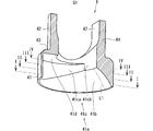
- FIG. 5 is a perspective view showing an example of the configuration of the inner member 4, and FIGS. 6 to 9 are views schematically showing a cut surface of the lower member 41 of the inner member 4.
- FIG. 5 shows one of two portions obtained by cutting the inner member 4 with a virtual cross section A1.
- the virtual cross section A1 is a surface including the virtual central axis Q1.
- 6 to 9 show the cross sections perpendicular to the virtual central axis Q1 in order from the lower side to the upper side.
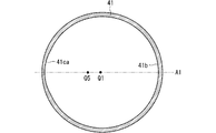
- FIGS. 6 to 9 schematically show virtual cut surfaces along the lines II, II-II, III-III and IV-IV shown in FIG. 5, respectively. .. That is, FIG. 6 shows a cross section of the lower member 41 at the lowermost position, and FIG. 9 shows a cross section of the lower member 41 at the uppermost position.
- the partial spherical surface 41b has a curved shape along the virtual spherical surface B1 of the head 22, and abuts on the head 22. Since the partial spherical surface 41b comes into contact with the head 22 from above, it can be grasped that the partial spherical surface 41b is the lower surface of the inner member 4.
- the partial spherical surface 41b has a shape that is substantially symmetrical with respect to the virtual cross section A1.
- the virtual cross section A1 is a surface including the virtual central axis Q1, and is shown by a chain double-dashed line in FIGS. 6 to 8. With reference to FIGS.
- the partial spherical surface 41b is formed only in a part of the inner member 4 in the circumferential direction in each cross section, and the length of the partial spherical surface 41b in the circumferential direction becomes shorter toward the upper side. There is. Further, the partial spherical surface 41b approaches the virtual central axis Q1 as it moves upward.
- the interference surface 41c extends upward from the upper end edge of the partial spherical surface 41b.
- the interference surface 41c forms a moving space H1 in which the interference portion 26 of the head 22 moves.
- the interference portion 26 moves around the center of the head 22 in the moving space H1.
- the interference surface 41c limits the rotation range of the head 22.
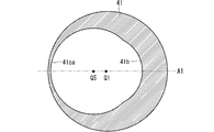
- the interference surface 41c also has a shape substantially symmetrical with respect to the virtual cross section A1, and is composed of an arc column surface 41ca and an arc column surface 41cc.
- the arc pillar surface 41ca has a shape along a cylindrical surface centered on the virtual central axis Q5. However, the arc pillar surface 41ca is formed only on a part of the inner member 4 in the circumferential direction. As illustrated in FIGS. 6 to 8, in the cross section passing through the partial spherical surface 41b, both ends in the circumferential direction of the arc column surface 41ca are continuous with both ends in the circumferential direction of the partial spherical surface 41b, respectively.
- the column surface 41ca and the partial spherical surface 41b form an annular shape as a whole.
- the virtual central axis Q5 is an axis located on the virtual cross section A1 and deviated from the virtual central axis Q1, and is substantially parallel to the virtual central axis Q1.
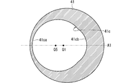
- the arc pillar surface 41cc is located above the partial spherical surface 41b.
- the arc pillar surface 41cc has a shape along a cylindrical surface centered on the virtual central axis Q1. However, the arc pillar surface 41cc is formed only partially in the circumferential direction of the inner member 4. As illustrated in FIG. 9, in the cross section above the partial spherical surface 41b, both ends in the circumferential direction of the arc column surface 41cc are continuous with both ends in the circumferential direction of the arc column surface 41ca, respectively, and the arc column surface in the cross section.
- the 41ca and the arcuate column surface 41cc form an annular shape as a whole.
- the upper end peripheral edge of the arc pillar surface 41ca is connected to the outer peripheral edge of the top surface 41d.
- the top surface 41d has a crescent-shaped shape when viewed along the virtual central axis Q1 (see also FIG. 5).
- the inner peripheral edge of the top surface 41d is continuous with the lower end peripheral edge of the inner peripheral surface of the side wall 42, which will be described later, and the upper end peripheral edge of the arc pillar surface 41cc is also continuous with the lower end peripheral edge of the inner peripheral surface of the side wall 42.
- a pair of side walls 42 are erected at the upper end of the lower member 41.
- the pair of side walls 42 and the lower member 41 may be integrally formed of the same material.
- the pair of side walls 42 are arranged so as to face each other in the direction in which the pair of side walls 52 of the outer member 5 face each other. In the illustrated example, the opposite directions of the side walls 42 are included in the virtual cross section A1.
- the pair of side walls 42 are located between the pair of side walls 52 of the outer member 5, respectively, with the inner member 4 located inside the outer member 5.
- a rod 130 is inserted between the pair of side walls 42.
- a part of the rod 130 in the longitudinal direction is inserted between the pair of side walls 42, and the other part protrudes from both sides of the inner member 4.
- the upper ends of the pair of side walls 42 are located below the upper ends of the rods 130 with the rods 130 inserted.
- a step 43 is formed between the outer peripheral surface of the pair of side walls 42 and the upper end surface of the lower member 41.
- the inner peripheral surfaces 52a of the pair of side walls 52 are located inside the inner peripheral surface 51a of the tubular member 51, and the inner peripheral surfaces 51a and 52a are mutually interposed via the stopper surfaces 53a. Be connected.
- the screw assembly 1 also includes a C-shaped member 6.
- the C-shaped member 6 has a C-shape. That is, the C-shaped member 6 has a shape obtained by cutting a ring shape in a part in the circumferential direction thereof.
- the inner peripheral surface of the C-shaped member 6 has a flat cylindrical shape along the flat band portion 25 of the head 22, and the outer peripheral surface has a curved shape along the virtual spherical surface B1 of the head 22.
- the width of the C-shaped member 6 is substantially equal to the width of the flat band portion 25 of the head 22.
- the inner diameter of the C-shaped member 6 is substantially the same as the diameter of the flat band portion 25, or slightly smaller than the diameter of the flat band portion 25.
- the C-shaped member 6 is elastically deformable.
- the C-shaped member 6 is attached to the flat band portion 25 of the head 22 so that its inner peripheral surface faces the flat band portion 25 of the head 22.
- the structure composed of the head 22 and the C-shaped member 6 can be made closer to a spherical shape.
- FIG. 10 is a diagram schematically showing an example of a state in which the screw assembly 1 is being assembled.
- the medical worker inserts the inner member 4 into the outer member 5. Specifically, the inner member 4 is inserted into the inner member 5 through the lower opening 5b of the outer member 5. In this state, the inner member 4 is not fixed to the outer member 5 and can move along the virtual central axis Q1. In the example of FIG. 10, the state in which the inner member 4 is located at the upper position is shown.
- the width of the cylindrical surface 51d (width along the virtual center axis Q2) is different in the circumferential direction.
- the width of the cylindrical surface 51d increases toward the right side.
- the length L1 of the partial spherical surface 41b of the inner member 4 (the length in the cross section including the virtual central axis Q1: also see FIG. 5) is also different in the circumferential direction.
- the length L1 of the partial spherical surface 41b increases toward the right side.
- the medical worker inserts the inner member 4 into the outer member 5 in a posture in which the long portion of the partial spherical surface 41b having a length L1 is close to the wide portion of the cylindrical surface 51d.
- the medical worker inserts the C-shaped member 6 into the outer member 5. Specifically, the medical worker elastically deforms the C-shaped member 6 so that both ends of the C-shaped member 6 come close to each other. As a result, the outer diameter of the C-shaped member 6 can be made smaller than the diameter of the lower opening 5b of the outer member 5.
- the medical worker inserts the reduced diameter C-shaped member 6 into the inside through the lower opening 5b of the outer member 5 and fits it into the spherical concave surface 51c.
- the medical worker fits the C-shaped member 6 into the spherical concave surface 51c so that the inner peripheral surface of the C-shaped member 6 is parallel to the cylindrical surface 51d of the outer member 5.
- the inner peripheral surface of the C-shaped member 6 and the cylindrical surface 51d form one continuous cylindrical surface.
- the medical worker inserts the head 22 of the screw 2 into the outer member 5.
- the medical staff tilts the screw 2 with respect to the outer member 5 so that the flat band portion 25 of the head 22 is along the peripheral edge of the lower opening 5b of the outer member 5.
- the medical staff inclines the screw 2 so that the virtual central axis Q4 of the flat band portion 25 substantially coincides with the virtual central axis Q2 of the cylindrical surface 51d of the outer member 5.
- the medical worker adjusts the inclined posture of the screw 2 so that the interference portion 26 faces the partial spherical surface 41b of the inner member 4.
- the interference portion 26 faces the long portion of the partial spherical surface 41b having a length L1.
- the interference portion 26 is located on the right side with respect to the virtual central axis Q1, and the screw 2 is tilted so that the screw body 21 extends to the lower left.
- the head 22 of the screw 2 can be inserted and removed from the outer member 5 via the lower opening 5b in this state.
- the rotation position of the head 22 with respect to the outer member 5 in this state is referred to as a reference rotation position.
- the medical worker inserts the head 22 into the inside through the lower opening 5b of the outer member 5 while maintaining this reference rotation position.
- the C-shaped member 6 is attached to the flat band portion 25 of the head 22, and thereafter, the C-shaped member 6 rotates integrally with the head 22.
- FIG. 11 is a cross-sectional view schematically showing an example of a state in which the screw assembly 1 is being assembled.
- the head 22 of the screw 2 is located inside the outer member 5, and the rotation position thereof is the reference rotation position. Even in this state, the inner member 4 is located at the upper position. When the inner member 4 is located in the upper position, the inner member 4 does not restrict the rotation of the head 22.
- the space inside the outer member 5 occupied by the interference portion 26 of the head 22 at the reference rotation position is referred to as a predetermined space H2.
- the inner member 4 is located in the upper position, the inner member 4 is located above the predetermined space H2.
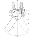
- FIG. 12 is a diagram schematically showing an example of how the head 22 rotates with respect to the coupling member 3.
- the inner member 4 is located at the upper position.
- the screw body 21 of the screw 2 abuts on the lower end of the outer member 5, or the interference portion 26 of the head 22 abuts on the cylindrical surface 51b of the outer member 5, so that the head 22 rotates with respect to the coupling member 3.
- the range is defined.
- the rotation range of the head 22 is indicated by the rotation range R1.
- the rotation range of the head 22 indicates the angle range of the inclination angle of the screw body 21 with respect to the outer member 5.
- the rotation range R1 is the virtual central axis Q1. It is set almost isotropically around.
- FIG. 13 is a cross-sectional view schematically showing an example of a state in which the screw assembly 1 is being assembled.
- the interference portion 26 of the head 22 does not face the partial spherical surface 41b of the inner member 4.
- the interference portion 26 of the head 22 is located in the moving space H1.
- the interference portion 26 may be moved to a position where the interference portion 26 does not face the partial spherical surface 41b of the inner member 4.
- FIG. 14 is a cross-sectional view schematically showing an example of a state in which the screw assembly 1 is being assembled.
- the inner member 4 is located at the lower position.
- the partial spherical surface 41b of the inner member 4 comes into contact with at least one of the partial spherical surface portion 23, the partial spherical surface portion 24, and the C-shaped member 6 of the screw 2.
- a part of the inner member 4 (referred to as an interference portion 411) is located in the predetermined space H2.
- the lower surface of the interference portion 411 is a long portion of the partial spherical surface 41b having a length L1.
- the interference portion 411 of the inner member 4 can interfere with the interference portion 26 of the head 22 as described in detail later.
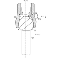
- FIG. 15 is a diagram schematically showing an example of how the head 22 rotates with respect to the coupling member 3.
- the inner member 4 is located at the lower position.
- the interference portion 26 of the screw 2 is located in the moving space H1 surrounded by the interference surface 41c of the inner member 4.
- the inner member 4 can limit the rotation range of the head 22.
- the rotation range of the head 22 is defined by the interference portion 26 of the screw 2 coming into contact with the interference surface 41c of the inner member 4.
- the rotation range of the head 22 in this state is shown by the rotation range R2. Since the interference portion 26 comes into contact with the interference surface 41c of the inner member 4 located inside the cylindrical surface 51b of the outer member 5, the rotation range R2 is smaller than the rotation range R1.
- the interference portion 411 of the inner member 4 is located in the predetermined space H2, the interference portion 26 cannot move to the predetermined space H2, and the head 22 cannot be positioned at the reference rotation position. That is, the rotation range R1 includes the reference rotation position, whereas the rotation range R2 does not include the reference rotation position.
- the rotation range R2 is set biased with respect to the virtual center axis Q1.
- the screw body 21 can swing around the head 22 on the right side of the virtual center axis Q1, but cannot move much to the opposite side.
- the screw 2 of the screw assembly 1 on the right side may extend to the right side with respect to the coupling member 3, and the screw 2 of the screw assembly 1 on the left side may extend to the coupling member 3. It suffices if it can extend to the left side. Therefore, even if the rotation range R2 of the head 22 is biased with respect to the virtual central axis Q1, there is no problem in using the screw assembly 1.
- the upper limit value of the rotation range R2 is, for example, about 35 degrees.
- This screw assembly 1 is embedded in the bone of the human body as follows. First, the medical staff displaces the screw 2 with respect to the coupling member 3 about the head 22 so that the virtual central axis Q3 is along the virtual central axis Q1 (see FIG. 14). In this state, the head surface of the interference portion 26 can be visually recognized from the upper opening 5a of the outer member 5. Next, the medical worker inserts a tool (not shown) into the upper opening 5a of the outer member 5 and fits it into the fitting hole 27 formed on the crown surface of the interference portion 26. Then, the medical worker rotates the tool to rotate the screw 2 around the virtual central axis Q1 to implant the screw body 21 in the target bone.
- a tool not shown
- the medical staff adjusts the posture of the coupling member 3. Specifically, the medical staff rotates the coupling member 3 with respect to the head 22 of the screw 2 at a rotation position suitable for inserting the rod 130.
- the coupling member 3 cannot be moved to the reference rotation position with respect to the head 22. Therefore, the connecting member 3 is unlikely to come off from the head 22 during the work.
- gravity acts on the inner member 4 downward the inner member 4 can be maintained at a lower position by gravity.
- the inner member 4 may be maintained in the lower position by the frictional force between the inner member 4 and the outer member 5.
- the inner member 4 and the outer member 5 may have a temporary locking structure. The inner member 4 may be maintained in the lower position by temporarily locking the inner member 4 to the outer member 5.
- the medical worker inserts the rod 130 through the upper opening 5a of the outer member 5, and screwes the fastening member 7 into the inner peripheral surface 52a of the outer member 5 using a predetermined tool.
- the fastening member 7 presses the rod 130, the inner member 4, and the head 22 downward, and these are integrally fastened.
- the rod 130 can be connected to the screw assembly 1 while the screw assembly 1 is transplanted to the target bone.
- the inner member 4 has a function of pressing the head 22 to hold the head 22 together with the outer member 5, and limits the rotation range of the screw 2 with respect to the coupling member 3 to the rotation range R2. Includes a function that makes it difficult to pull out 2. Therefore, it is possible to make it difficult to separate each element of the screw assembly 1 with a simple operation. In addition, the number of parts can be reduced and management can be facilitated as compared with the case where these are composed of separate members.
- the inner member 4 is formed with a hollow portion penetrating the inner member 4 along the virtual central axis Q1. Therefore, the medical staff can rotate the screw 2 by using a predetermined tool with the inner member 4 and the head 22 of the screw 2 arranged inside the outer member 5 (see FIG. 14). Therefore, in this state, the screw 2 can be embedded in the target bone.
- the inner member 4 can be pressed downward to be positioned at the lower position while the rod 130 is coupled to the coupling member 3. Therefore, by the fastening, the inner member 4 and the head 22 can be fixed while exerting the function of limiting the rotation range of the inner member 4.
- the movement of the inner member 4 to the lower position is not limited to the fastening of the fastening member 7, and may be performed by various methods.
- the partial spherical surface 41b of the inner member 4 comes into contact with the head 22 and the C-shaped member 6. Therefore, the contact area between the structure composed of the head 22 and the C-shaped member 6 and the inner member 4 can be increased, and the fixing force of the structure can be improved.
- the interference portion 26 is a predetermined space of the inner space of the outer member 5 which is closer to the inner peripheral surface 51a than the central portion thereof. It is located in H2. More specifically, at the reference rotation position, the interference portion 26 does not intersect the virtual central axis Q2. In other words, at the reference rotation position, the interference portion 26 is positioned deviating from the virtual center axis.
- the moving space H1 is a space among the internal spaces of the outer member 5 that does not include at least the predetermined space H2.
- the predetermined space H2 when the predetermined space H2 is located at the central portion of the internal space, that is, on the side of the virtual central axis Q1, the volume of the moving space H1 becomes small, which in turn narrows the rotation range R2.
- the predetermined space H2 since the predetermined space H2 does not intersect with the virtual central axis Q1 and is located at the edge of the space, the moving space H1 can be set large and the rotation range R2 can be widened.
- the flat band portion 25 of the head 22 is inclined with respect to the virtual central axis Q3 in which the screw body 21 extends (see FIG. 10).
- the virtual central axis Q4 of the flat zone portion 25 intersects the virtual central axis Q3. Therefore, at the reference rotation position, the screw body 21 extends along the direction inclined with respect to the virtual central axis Q2 of the cylindrical surface 51d of the outer member 5.
- the reference rotation position substantially coincides with the left end of the rotation range R1.
- the inner member 4 limits the rotation range of the head 22 to the rotation range R2 that does not include the reference rotation position (see FIG. 15).
- the left end of the rotation range R2 is located on the right side of the left end (reference rotation position) of the rotation range R1.
- the rotation range R2 becomes narrower than the rotation range R1.
- FIG. 16 is a diagram schematically showing an example of inserting the screw 2A, which is another example of the screw 2, into the coupling member 3.
- the screw 2A differs from the screw 2 in the extending direction of the screw body 21 with respect to the head 22.
- the virtual central axis Q3 on which the screw main body 21 extends substantially coincides with the virtual central axis Q4 of the flat band portion 25.
- the screw body 21 extends in a direction closer to the virtual central axis Q1.
- FIG. 17 is a diagram schematically showing an example of how the head 22 of the screw 2A rotates with respect to the coupling member 3.
- the interference portion 26 is retracted from the predetermined space H2 to the moving space H1, and the inner member 4 is located at a lower position.
- the rotation range of the head 22 is limited to the rotation range R2A.
- the rotation range R2A is narrower than the rotation range R2.
- the rotation range R2 can be set wide by inclining the flat band portion 25 of the head 22 with respect to the virtual central axis Q3 on which the screw body 21 extends.
- the interference surface 41c of the inner member 4 has a curved shape along the virtual cylindrical surface, and the outer peripheral edge of the crown surface of the interference portion 26 of the head 22 has a circular shape. According to this, when the head 22 is rotated while the outer peripheral edge of the interference portion 26 is in contact with the interference surface 41c, the interference portion 26 can smoothly slide along the interference surface 41c. Therefore, the medical worker can smoothly displace the screw 2 with respect to the outer member 5 around the head 22.
- the virtual center axis Q2 of the cylindrical surface 51d of the outer member 5 is inclined with respect to the virtual center axis Q1 of the outer member 5. The effects caused by this inclination will be described below.
- FIG. 18 is a diagram schematically showing an example of the configuration of the outer member 5A, which is another example of the outer member 5.
- the virtual center axis Q2 of the cylindrical surface 51d coincides with the virtual center axis Q1 of the outer member 5A.
- the interference portion 26 faces the moving space H1
- the virtual center axis Q4 of the flat band portion 25 of the screw 2 coincides with the virtual center axis Q2 of the cylindrical surface 51d, so that in this state.
- the head 22 of the screw 2 can be inserted into the inside through the lower opening 5b of the outer member 5A. Therefore, the rotation position of the head 22 with respect to the outer member 5A shown by the solid line in FIG. 18 is also a reference rotation position.
- the interference portion 26 faces the moving space H1. Therefore, if the head 22 is inserted into the outer member 5A in this state, the rotation position of the head 22 can be positioned at the reference rotation position in FIG. 18 even if the inner member 4 is moved to the lower position. That is, the inner member 4 cannot appropriately limit the rotation range of the screw 2.
- the head 22 of the screw 2 may be inserted into the outer member 5A in the posture indicated by the alternate long and short dash line (virtual line). That is, the head 22 may be inserted into the outer member 5A in a posture in which the interference portion 26 faces the predetermined space H2. Then, as illustrated in FIG. 14, the screw 2 is displaced around the head 22 so that the interference portion 26 is located in the moving space H1, and the inner member 4 is moved to the lower position as illustrated in FIG. Then, the rotation range of the screw 2 can be limited to the rotation range R2 that does not include the reference rotation position.
- the head 22 of the screw 2 can be inserted into the outer member 5A even in the posture of FIG. 16 in which the function of limiting the rotation range of the inner member 4 cannot be exerted, so that the medical worker fails to assemble. there's a possibility that. That is, if the outer member 5A is used, the workability is not so high.
- FIG. 19 is a diagram schematically showing an example of how the head 22 of the screw 2 is inserted into the outer member 5.
- the interference portion 26 of the screw 2 faces the moving space H1.
- the virtual central axis Q4 of the flat band portion 25 of the screw 2 coincides with the virtual central axis Q2 of the cylindrical surface 51d of the outer member 5.
- the screw body 21 extends to the wider side (width along the virtual center axis Q2) of the cylindrical surface 51d of the outer member 5 with respect to the virtual center axis Q1.
- the screw body 21 extends to the lower right. Therefore, the portion 211 of the screw main body 21 closest to the flat band portion 25 is located on the wide portion side (right side in FIG. 19) of the cylindrical surface 51d.
- the minimum distance ⁇ d minimum value of the distance along the virtual center axis Q2
- FIG. 20 is a diagram schematically showing an example of how the screw 2 is inserted into the outer member 5.
- the portion 211 of the screw body 21 comes into contact with the lower end of the outer member 5 before being inserted to an appropriate position. That is, in this posture, the head 22 cannot be inserted into the outer member 5.
- the medical worker rotates the head 22 around the virtual central axis Q2 so that the head 22 can be inserted into the outer member 5.
- the head 22 is inserted into the outer member 5 in the posture shown in FIG.
- the screw 2 is displaced around the head 22 and the inner member 4 is moved downward so that the interference portion 26 is located in the moving space H1 as described above.
- the rotation range of the head 22 is limited to the rotation range R2 that does not include the reference rotation position. In other words, the head 22 of the screw 2 can be made difficult to come off from the lower opening 5b of the outer member 5.
- the medical worker can easily assemble the screw assembly 1 and improve workability. can do.
- the screw assembly 1 includes a C-shaped member 6.
- the structure composed of the head 22 and the C-shaped member 6 can be made closer to a spherical shape. Therefore, the contact area between the partial spherical surface 41b of the inner member 4 and the structure can be improved, and the holding force of the head 22 can be improved.
- the outer peripheral edge of the interference portion 26 does not necessarily have to be circular, and may have an elliptical shape.
- the outer peripheral edge of the interference portion 26 may have a smooth star shape. Each vertex of this star shape should be located on a predetermined virtual circle. This also allows the head 22 to rotate smoothly while keeping the outer peripheral edge of the interference portion 26 in contact with the interference surface 41c of the inner member 4.
- the screw 2 can be rotated around the virtual central axis Q3 by using a nut driver having a cross section having substantially the same shape as the outer peripheral edge of the interference portion 26.
- the interference portion 26 projects outward in the radial direction of the head 22, the interference portion 26 is not necessarily limited to this.
- the interference portion 26 may be a recess recessed inward in the radial direction of the head 22.
- the inner member 4 may include an interference portion that is loosely inserted into the recess while being located at a lower position. When the inner member 4 is located at the upper position, the interference portion is located outside the recess and does not come into contact with the head 22.
- the interference portion is, for example, a rod-shaped protrusion.
- the head 22 can rotate within a rotation range corresponding to the gap between the interference portion and the recess. That is, the rotation range of the head 22 is limited to the rotation range R2 by the interference portion contacting the peripheral edge of the recess.
- FIG. 23 is a cross-sectional view schematically showing an example of the configuration of the screw assembly 1 as another embodiment.
- the inner member 4 is located at a lower position, and the rotation of the head 22 to the reference rotation position is restricted by the contact between the inner member 4 and the interference portion 26.
- the leftmost position of the rotation range R21 is defined by the contact between the inner member 4 and the interference portion 26.
- the screw body 21 can come into contact with a part of the lower end portion of the outer member 5 by rotating around the head 22.
- the diameter of the arc pillar surface 41ca of the inter member 4 is set to be larger. Therefore, when the head 22 is rotated from the left side to the right side in FIG. 23, the screw body 21 hits the lower end portion of the outer member 5 before the interference portion 26 abuts on the arc pillar surface 41c of the inner member 4. Touch. That is, in the present embodiment, the rotation range R21 of the head 22 is also defined by the contact between the screw body 21 and the lower end portion of the outer member 5. In the example of FIG. 23, the rightmost position of the rotation range R21 is defined by the contact between the lower end portion of the outer member 5 and the screw body 21, but at this time, the inner member 4 and the interference portion 26 do not abut. ..
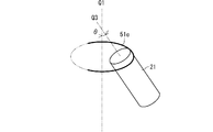
- FIG. 24 is a diagram schematically showing an example of a portion 51e of the lower end portion of the outer member 5 that can come into contact with the screw body 21.
- the portion 51e has an arc shape, and the plane along which the portion 51e follows is substantially perpendicular to the virtual central axis Q1.
- the screw body 21 is rotatable about the head 22 within a range along the arc shape of the portion 51e.
- the portion 51e of the outer member 5 is substantially perpendicular to the virtual central axis Q1, but is not necessarily limited to this.
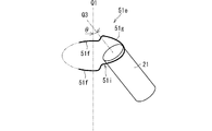
- FIG. 25 is a diagram schematically showing another example of the portion 51e of the outer member 5 as another embodiment.
- the portion 51e has a first region 51f and a second region 51g.
- the second region 51g is closer to the first opening 5a of the outer member 5 than the first region 51f.
- the second region 51g is located above the first region 51f.
- the portion 51e has a recess 51i recessed on the side of the first opening 5a, the recess 51i corresponds to the second region 51g, and the portions of the portion 51e on both sides of the recess 51i are the first region. It corresponds to 51f.
- the rotation range of the screw body 21 regulated by the portion 51e of the outer member 5 can be increased in a part thereof.
- the rotation range of the screw body 21 can be expanded in the second region 51 g.
- FIG. 26 is a diagram schematically showing an example of the configuration of the outer member 5 as another embodiment.
- the portion 5e may be inclined with respect to the plane perpendicular to the virtual central axis Q1 of the outer member 5. More specifically, the portion 5e may be along a predetermined virtual plane, and the virtual plane may be inclined with respect to a plane perpendicular to the virtual central axis Q1.
- the portion 5e has a shape along a part of the ellipse, and is inclined toward the first opening 5a side (upper side along the virtual central axis Q1 in FIG. 26) as the distance from both ends thereof. ing.
- the upper limit of the rotation range of the screw body 21 regulated by the lower end portion of the outer member 5 can be increased on one side.
- the upper limit of the rotation range of the screw body 21 can be increased on the right side.
- the inclination angle of the virtual plane with respect to the plane perpendicular to the virtual central axis Q1 is, for example, 1 to 20 °.
- the portion 51e When the portion 5e is inclined with respect to the plane perpendicular to the virtual central axis Q1 (FIG. 26), the portion 51e naturally has the first region 51f and the second region 51g.
- the first region 51f is regarded as both end portions of the portion 51e
- the portion between the both end portions can be regarded as the second region 51g.
- outer member 5 is called an "outer” member in that it is located outside the inner member 4, another member may be arranged outside the outer member 5.
- the present invention is not necessarily limited to this.
- the body of the internal fixation member may be installed and fixed to the bone of a living body, and its shape can be changed as appropriate.
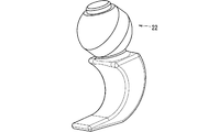
- the body of the internal fixation member may be a hook 21A that engages with the bone of a living body as shown in FIG.
- the hook 21A has a curved claw shape, and the hook 21A engages with the outer peripheral surface of the bone.
- the body of the internal fixation member may be a pin that is press-fitted or driven into the bone of a living body.
- the pin has, for example, a rod-like shape with a sharp tip.
- the pin is press-fitted or driven into the bone from its tip. Since the screw thread of the screw body 21 is not shown in FIG. 2, the shape of the internal fixing member in which the body of the internal fixing member is a pin has the same shape as the shape shown as the screw 2 in FIG. doing. However, in this internal fixing member, the head 22 does not have to have the fitting hole 27.
- the internal fixing member body is transplanted inside the human body, it is not necessarily limited to this, and it may be transplanted to an animal other than human.
- Screw assembly Screw 21 Screw body 22 Head 23, 24 Spherical part 25 Flat band part 26 Interference part 27 Fitting hole 3 Coupling member 4 Inner member 41a Inner peripheral surface of inner member 411 Interference part 5 Outer member 5a First opening ( Upper opening) 5b 2nd opening (lower opening) 51a Inner peripheral surface of outer member 51c Spherical concave surface 51d Cylindrical surface 6 C-shaped member 7 Fastening member H2 Predetermined space
Landscapes
- Health & Medical Sciences (AREA)
- Orthopedic Medicine & Surgery (AREA)
- Life Sciences & Earth Sciences (AREA)
- Neurology (AREA)
- Surgery (AREA)
- Heart & Thoracic Surgery (AREA)
- Engineering & Computer Science (AREA)
- Biomedical Technology (AREA)
- Nuclear Medicine, Radiotherapy & Molecular Imaging (AREA)
- Medical Informatics (AREA)
- Molecular Biology (AREA)
- Animal Behavior & Ethology (AREA)
- General Health & Medical Sciences (AREA)
- Public Health (AREA)
- Veterinary Medicine (AREA)
- Surgical Instruments (AREA)
Priority Applications (2)
| Application Number | Priority Date | Filing Date | Title |
|---|---|---|---|
| JP2021561436A JP7282206B2 (ja) | 2019-11-29 | 2020-11-25 | 内固定部材セットおよび内固定部材 |
| US17/777,523 US12089879B2 (en) | 2019-11-29 | 2020-11-25 | Internal fixation member set and internal fixation member |
Applications Claiming Priority (2)
| Application Number | Priority Date | Filing Date | Title |
|---|---|---|---|
| JP2019-216768 | 2019-11-29 | ||
| JP2019216768 | 2019-11-29 |
Publications (1)
| Publication Number | Publication Date |
|---|---|
| WO2021106900A1 true WO2021106900A1 (ja) | 2021-06-03 |
Family
ID=76130532
Family Applications (1)
| Application Number | Title | Priority Date | Filing Date |
|---|---|---|---|
| PCT/JP2020/043732 Ceased WO2021106900A1 (ja) | 2019-11-29 | 2020-11-25 | 内固定部材セットおよび内固定部材 |
Country Status (3)
| Country | Link |
|---|---|
| US (1) | US12089879B2 (enExample) |
| JP (1) | JP7282206B2 (enExample) |
| WO (1) | WO2021106900A1 (enExample) |
Families Citing this family (1)
| Publication number | Priority date | Publication date | Assignee | Title |
|---|---|---|---|---|
| US20240398444A1 (en) * | 2021-09-14 | 2024-12-05 | Agmspine, Sia | A polyaxial spinal screw |
Citations (3)
| Publication number | Priority date | Publication date | Assignee | Title |
|---|---|---|---|---|
| JP2007502677A (ja) * | 2003-08-20 | 2007-02-15 | ウォーソー・オーソペディック・インコーポレーテッド | 例えば脊椎手術用の、多軸型整形外科デバイスおよびシステム |
| US20080288002A1 (en) * | 2006-12-29 | 2008-11-20 | Abbott Spine Inc. | Spinal Stabilization Systems and Methods |
| JP2010515552A (ja) * | 2007-01-12 | 2010-05-13 | ランクス インコーポレイテッド | 骨固定具組立体 |
Family Cites Families (6)
| Publication number | Priority date | Publication date | Assignee | Title |
|---|---|---|---|---|
| ATE476929T1 (de) | 2000-06-30 | 2010-08-15 | Warsaw Orthopedic Inc | Zwischenwirbel-verbindungsvorrrichtung |
| US7066937B2 (en) | 2002-02-13 | 2006-06-27 | Endius Incorporated | Apparatus for connecting a longitudinal member to a bone portion |
| WO2008082836A1 (en) * | 2006-12-29 | 2008-07-10 | Abbott Spine Inc. | Spinal stabilization systems and methods |
| US9480501B2 (en) * | 2013-10-21 | 2016-11-01 | Blackstone Medical, Inc. | Modular pedicle screw |
| US10575878B2 (en) * | 2016-07-21 | 2020-03-03 | Warsaw Orthopedic, Inc. | Spinal implant system and methods of use |
| US11076888B2 (en) * | 2017-07-28 | 2021-08-03 | Anza Innovations, Inc. | Spinal stabilization system including bottom loading wide angulation polyaxial rod anchor assemblies |
-
2020
- 2020-11-25 US US17/777,523 patent/US12089879B2/en active Active
- 2020-11-25 WO PCT/JP2020/043732 patent/WO2021106900A1/ja not_active Ceased
- 2020-11-25 JP JP2021561436A patent/JP7282206B2/ja active Active
Patent Citations (3)
| Publication number | Priority date | Publication date | Assignee | Title |
|---|---|---|---|---|
| JP2007502677A (ja) * | 2003-08-20 | 2007-02-15 | ウォーソー・オーソペディック・インコーポレーテッド | 例えば脊椎手術用の、多軸型整形外科デバイスおよびシステム |
| US20080288002A1 (en) * | 2006-12-29 | 2008-11-20 | Abbott Spine Inc. | Spinal Stabilization Systems and Methods |
| JP2010515552A (ja) * | 2007-01-12 | 2010-05-13 | ランクス インコーポレイテッド | 骨固定具組立体 |
Also Published As
| Publication number | Publication date |
|---|---|
| JPWO2021106900A1 (enExample) | 2021-06-03 |
| US20220395297A1 (en) | 2022-12-15 |
| JP7282206B2 (ja) | 2023-05-26 |
| US12089879B2 (en) | 2024-09-17 |
Similar Documents
| Publication | Publication Date | Title |
|---|---|---|
| US11484348B2 (en) | Uni-planer bone fixation assembly | |
| US7892259B2 (en) | Bone anchoring device | |
| US9339304B2 (en) | High angulation polyaxial bone anchoring device | |
| JP6076648B2 (ja) | 多軸骨アンカー固定システム | |
| JP5760013B2 (ja) | 多軸の骨接合アンカーのためのロック要素、骨接合板の組立品、および工具 | |
| KR101197844B1 (ko) | 다중-축 나사용 키형 크라운 배향 | |
| US9005249B2 (en) | Spinal rod connector assembly | |
| US9572598B2 (en) | Uniplanar surgical screw assembly | |
| JP6073597B2 (ja) | 拡大した回動角度を有する多軸骨アンカー固定装置 | |
| US20170340360A1 (en) | Bone fixation assembly | |
| US20050203515A1 (en) | Bone anchor assemblies | |
| US20060235385A1 (en) | Low profile polyaxial screw | |
| EP2570090A1 (en) | Polyaxial bone anchoring device with enlarged pivot angle | |
| US20120095512A1 (en) | Cross connectors | |
| JPH078505A (ja) | 椎骨継手 | |
| US20130150904A1 (en) | Monoplanar bone anchoring device with selectable pivot plane | |
| JP2015526196A (ja) | アンカーインアンカーシステム | |
| EP3419537B1 (en) | Polyaxial bone fixation element | |
| WO2021106900A1 (ja) | 内固定部材セットおよび内固定部材 |
Legal Events
| Date | Code | Title | Description |
|---|---|---|---|
| 121 | Ep: the epo has been informed by wipo that ep was designated in this application |
Ref document number: 20891559 Country of ref document: EP Kind code of ref document: A1 |
|
| ENP | Entry into the national phase |
Ref document number: 2021561436 Country of ref document: JP Kind code of ref document: A |
|
| NENP | Non-entry into the national phase |
Ref country code: DE |
|
| 122 | Ep: pct application non-entry in european phase |
Ref document number: 20891559 Country of ref document: EP Kind code of ref document: A1 |