WO2021106884A1 - 精鉱バーナー、自溶炉及び反応ガスの導入方法 - Google Patents
精鉱バーナー、自溶炉及び反応ガスの導入方法 Download PDFInfo
- Publication number
- WO2021106884A1 WO2021106884A1 PCT/JP2020/043695 JP2020043695W WO2021106884A1 WO 2021106884 A1 WO2021106884 A1 WO 2021106884A1 JP 2020043695 W JP2020043695 W JP 2020043695W WO 2021106884 A1 WO2021106884 A1 WO 2021106884A1
- Authority
- WO
- WIPO (PCT)
- Prior art keywords
- gas
- flow path
- tubular portion
- reaction
- flow velocity
- Prior art date
- Legal status (The legal status is an assumption and is not a legal conclusion. Google has not performed a legal analysis and makes no representation as to the accuracy of the status listed.)
- Ceased
Links
Images


Classifications
-
- C—CHEMISTRY; METALLURGY
- C22—METALLURGY; FERROUS OR NON-FERROUS ALLOYS; TREATMENT OF ALLOYS OR NON-FERROUS METALS
- C22B—PRODUCTION AND REFINING OF METALS; PRETREATMENT OF RAW MATERIALS
- C22B15/00—Obtaining copper
-
- C—CHEMISTRY; METALLURGY
- C22—METALLURGY; FERROUS OR NON-FERROUS ALLOYS; TREATMENT OF ALLOYS OR NON-FERROUS METALS
- C22B—PRODUCTION AND REFINING OF METALS; PRETREATMENT OF RAW MATERIALS
- C22B23/00—Obtaining nickel or cobalt
- C22B23/02—Obtaining nickel or cobalt by dry processes
-
- F—MECHANICAL ENGINEERING; LIGHTING; HEATING; WEAPONS; BLASTING
- F27—FURNACES; KILNS; OVENS; RETORTS
- F27D—DETAILS OR ACCESSORIES OF FURNACES, KILNS, OVENS OR RETORTS, IN SO FAR AS THEY ARE OF KINDS OCCURRING IN MORE THAN ONE KIND OF FURNACE
- F27D3/00—Charging; Discharging; Manipulation of charge
- F27D3/18—Charging particulate material using a fluid carrier
-
- Y—GENERAL TAGGING OF NEW TECHNOLOGICAL DEVELOPMENTS; GENERAL TAGGING OF CROSS-SECTIONAL TECHNOLOGIES SPANNING OVER SEVERAL SECTIONS OF THE IPC; TECHNICAL SUBJECTS COVERED BY FORMER USPC CROSS-REFERENCE ART COLLECTIONS [XRACs] AND DIGESTS
- Y02—TECHNOLOGIES OR APPLICATIONS FOR MITIGATION OR ADAPTATION AGAINST CLIMATE CHANGE
- Y02P—CLIMATE CHANGE MITIGATION TECHNOLOGIES IN THE PRODUCTION OR PROCESSING OF GOODS
- Y02P10/00—Technologies related to metal processing
- Y02P10/20—Recycling
Definitions
- the present invention relates to a concentrate burner, a flash smelting furnace, and a method for introducing a reaction gas.
- a flash smelting furnace is a smelting furnace used for smelting non-ferrous metals such as copper and nickel and for matte smelting.
- a shaft is provided on a reverberatory furnace type settler and reacts with raw materials from the top. It is a furnace that instantly oxidizes and melts by using the heat of oxidation of the raw material by blowing the gas to be used for.
- a concentrate burner that supplies raw materials and reaction gas into the furnace plays an important role in determining the performance of the flash smelting furnace.
- This concentrate burner affects the reaction efficiency of the raw material in the reaction shaft and the degree of reaction progress, and as a result, affects the processing capacity of the flash smelting furnace and the metal yield. It is desirable that the reaction in the reaction shaft in the flash smelting furnace proceeds quickly and that all the raw materials proceed uniformly at the same extent of reaction. Therefore, it is desirable that the raw material and the reaction gas are uniformly mixed.
- Patent Document 1 In order to improve the mixing of such raw materials and reaction gas, it is known that the main air supplied from the concentrate burner into the reaction shaft is swirled (Patent Document 1). Further, it is known that an oxygen blowing pipe is provided inside a tubular concentrate chute so as to surround a fuel burner, and a guide blade is provided at an opening thereof to supply a swirling flow (Patent Document 2).
- Patent Document 1 and Patent Document 2 do not positively generate a swirling flow in the region directly below such a raw material supply device, and there is room for improvement.
- the present invention has been made in view of the above problems, and an object of the present invention is to positively promote the mixing of the raw material and the reaction gas supplied into the flash smelting furnace to make the reaction uniform.
- the concentrate burner of the present invention is a concentrate burner that supplies a raw material into the flash smelting furnace and at least supplies a reaction gas that contributes to the reaction of the raw material into the flash smelting furnace, and is outside the lance.
- a first tubular portion that is provided and forms a raw material flow path for supplying the raw material into the flash smelting furnace with the lance, and a first tubular portion that is provided outside the first tubular portion and is provided.
- a second tubular portion forming an annular first gas flow path for supplying the reaction gas into the flash smelting furnace between the tubular portion 1 and the second tubular portion.
- a third tubular portion provided on the outside and forming an annular second gas flow path for supplying the reaction gas into the flash smelting furnace between the second tubular portion and the above.
- a swirling blade that projects into the first gas flow path and swirls the reaction gas that passes through the first gas flow path is provided.
- the swivel blade can be provided on the inner peripheral wall surface of the second tubular portion.
- the swivel blade can be arranged with a gap between it and the first tubular portion.
- the inclination angle of the swivel blade with respect to the axial direction of the lance can be in the range of 5 ° to 20 °, more preferably in the range of 10 ° to 15 °.
- the upper end portion of the swivel blade is located below the upper edge of the second tubular portion, and the first end portion is between the upper end portion of the swivel blade and the upper edge of the second tubular portion.
- a region may be provided to equalize the flow velocity of the gas introduced into the gas flow path of 1.
- the distance between the upper end portion of the swivel blade and the upper edge of the second tubular portion is preferably 100 mm or more. More preferably, it is 150 mm or more. More preferably, it is 200 mm or more.
- the time for passing between the upper end portion of the swivel blade and the upper edge of the second tubular portion can be between 0.5 msec and 3.7 msec.
- the flash smelting furnace of the present invention is equipped with the concentrate burner of the present invention.
- the method for introducing the reaction gas of the present invention is a first gas flow formed at least around the raw material flow path together with the raw material to be introduced into the flash smelting furnace through the raw material flow path formed in the concentrate burner.
- a method of introducing a reaction gas into the flash smelting furnace through a path and a second gas flow path formed around the first gas flow path which is a method of introducing the reaction gas through the first gas flow path.
- the discharged reaction gas is introduced into the flash smelting furnace as a swirling flow, and the reaction gas discharged through the second gas flow path surrounds the swirling flow and suppresses the diffusion of the swirling flow. This is a method of introducing the reaction gas to be introduced into the flash smelting furnace.
- the swirling blade provided at the lower end of the concentrate burner can promote the mixing of the raw material and the reaction gas to make the reaction uniform.
- FIG. 1 is a diagram schematically showing a configuration of a flash smelting furnace for copper smelting according to an embodiment.
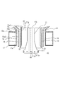
- FIG. 2 is a cross-sectional view of a charging portion provided at the tip of a concentrate burner included in the flash smelting furnace of the embodiment.
- FIG. 3 is an enlarged cross-sectional view of the input portion shown in FIG.
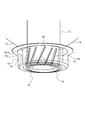
- FIG. 4 is a perspective explanatory view showing the arrangement of the swivel blades.
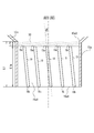
- FIG. 5 is an explanatory view of the mounting angle ⁇ of the swirl vane and the flow velocity equalization region.
- FIG. 6 is a graph showing an example of the simulation result of the flow velocity distribution at the outlet of the first gas flow path when the flow velocity equalization region is not provided.
- FIG. 1 is a diagram schematically showing a configuration of a flash smelting furnace for copper smelting according to an embodiment.
- FIG. 2 is a cross-sectional view of a charging portion provided at the tip of a concentrate burner
- the flash smelting furnace 100 includes a concentrate burner 1 and a furnace body 2.
- the concentrate burner 1 is a raw material supply device, and is a raw material concentrate (copper concentrate (CuFeS 2 etc.)), a main blower gas for reaction, an auxiliary gas for reaction, and a gas for dispersion (which also contributes to the reaction). Is supplied into the furnace body 2.
- the furnace body 2 includes a reaction shaft 3, a settler 4, and an uptake 5 in which the concentrate and the reaction gas are mixed.
- the main blower gas for reaction and the auxiliary gas for reaction are oxygen-enriched air
- the dispersion gas is air or oxygen-enriched air.
- FIG. 2 is an explanatory view showing an input portion 10 provided at the tip end portion of the concentrate burner 1.
- FIG. 3 is an enlarged cross-sectional view of the charging portion 10 shown in FIG.
- the charging unit 10 charges the raw material, the reaction gas, and the dispersion gas to the reaction shaft 3 side.
- the input portion 10 of the concentrate burner 1 is provided with a lance 11 provided at the center thereof and a first tubular portion 13 provided outside the lance 11 and forming a raw material flow path 12 between the lance 11 and the lance 11. Be prepared.
- the charging section 10 is also provided outside the first tubular section 13, and is an annular structure that supplies reaction gas into the flash smelting furnace 100 (reaction shaft 3) between the charging section 10 and the first tubular section 13.
- the second tubular portion 15a forming the first gas flow path 14 of the above is provided.
- the charging section 10 is provided outside the second tubular portion 15a, and is an annular structure that supplies reaction gas into the flash smelting furnace 100 (reaction shaft 3) between the charging section 10 and the second tubular portion 15a.
- a third tubular portion 17a forming the second gas flow path 16 of the above is provided.
- the charging unit 10 includes a swirling vane 19 that projects into the first gas flow path 14 and swirls the reaction gas that passes through the first gas flow path 14.
- the lance 11 is provided along the central axis AX extending in the vertical direction. Inside the lance 11, a third gas flow path 11a located at the center thereof and a fourth gas flow path 11b arranged around the third gas flow path 11a are provided. A reaction auxiliary gas as a part of the reaction gas passes through the third gas flow path 11a. Dispersion gas passes through the fourth gas flow path 11b. A hollow conical trapezoidal dispersion cone 111 is provided at the tip end portion (lower end portion) of the lance 11. On the lower side surface of the dispersion cone 111, a plurality of supply holes 111a for discharging the dispersion gas that has passed through the fourth gas flow path 11b into the reaction shaft 3 are formed.
- the supply hole 111a of the present embodiment is provided so that the gas discharge direction is the normal direction of the bottom circle of the dispersion cone 111, but the gas discharge direction is the normal direction of the bottom circle of the dispersion cone 111.
- the supply hole 111a may be provided so as to have an angle with respect to the supply hole 111a.
- the first tubular portion 13 is formed by a cylindrical member arranged so as to surround the lance 11.
- the first tubular portion 13 in the present embodiment is provided as a water cooling nozzle through which cooling water circulates.
- the raw material flow path 12 formed between the lance 11 and the first tubular portion 13 supplies the concentrate into the reaction shaft 3.
- the second tubular portion 15a is provided as a part of the inner tank member 15 arranged outside the first tubular portion 13.
- the inner tank member 15 includes a funnel-shaped portion 15b whose diameter increases upward, and also includes a cylindrical second tubular portion 15a which is continuously provided below the funnel-shaped portion 15b. ing.
- the funnel-shaped portion 15b forms a first air chamber 151 with the first tubular portion 13.
- the first air chamber 151 leads to the first gas flow path 14.
- the inner tank member 15 is provided so as to be removable.
- the third tubular portion 17a is provided as an inner peripheral wall portion of the cooling jacket 17 provided at the lower end portion of the charging portion 10. Cooling water circulates in the cooling jacket 17.
- the cooling jacket 17 is arranged above the cooling jacket 17 and is connected to a funnel-shaped outer tank member 18 whose diameter increases upward. Specifically, the cooling jacket 17 is attached to a collar-shaped portion 18a provided at the lower end portion of the outer tank member 18.
- the outer tank member 18 forms a second air chamber 181 with the inner tank member 15.
- the second air chamber 181 communicates with the second gas flow path 16.
- the concentrate burner 1 has a first gas supply system 21 and a second gas supply system 22.
- the first gas supply system 21 is branched into a first supply unit 21a and a second supply unit 21b.
- the first supply unit 21a supplies gas into the first air chamber 151.
- the second supply unit 21b supplies gas into the second air chamber 181.
- the first supply unit 21a is provided with a regulating valve 21a1 for adjusting the gas flow rate, whereby the amount of gas supplied into the first air chamber 151 and the amount of gas supplied into the second air chamber 181 are supplied. The ratio with the amount of gas can be adjusted.
- the second gas supply system 22 supplies gas into the lance 11. The total amount of gas supplied by the first gas supply system 21 and the total amount of gas supplied by the second gas supply system 22 can also be adjusted.
- the first supply unit 21a of the present embodiment is further branched into two routes.
- the first air chamber 151 is provided with gas inlets 151a at two places above the first air chamber 151, and the paths branched by the first supply unit 21a are connected to each of the first air chambers 151.
- the upper dimension of the first air chamber 151 is larger than the lower dimension.
- gas blowing ports When gas is blown into the first air chamber 151 having a large upper dimension, it is desirable to provide gas blowing ports at a plurality of places so that the gas is distributed over the entire area of the first air chamber 151.
- the plurality of gas inlets are provided so as to be radial with respect to the central portion of the first air chamber 151 or symmetrical with respect to the central axis AX. Therefore, in the present embodiment, gas outlets 151a are provided at two locations symmetrical with respect to the central axis AX.
- a swivel blade 19 is provided in the first gas flow path 14.
- the swivel blade 19 is provided on the inner peripheral wall surface 15a1 of the second tubular portion 15a so as to project into the first gas flow path 14.
- the swivel blade 19 also functions as a spacer between the first tubular portion 13 and the second tubular portion 15a. That is, the swivel blade 19 also has a function of maintaining a distance between the first tubular portion 13 and the second tubular portion 15a.
- the swivel blade 19 is arranged with a gap S1 between it and the first tubular portion 13.
- the reason why the gap S1 is provided in this way is to cope with the dimensional change due to the thermal expansion of the member.
- the distance that the second tubular portion 15a extends along the vertical direction is L1.
- the swivel blade 19 is provided on the second tubular portion 15a, but the upper end portion 19a of the swivel blade 19 is located below the upper edge 15a3 of the second tubular portion 15a.
- the vertical length of the swivel blade 19 is L1a.
- the flow velocity equalization region 30 is provided at a position where the funnel-shaped portion 15b transitions to the second tubular portion 15a.
- the flow velocity equalization region 30 is a region shown with hatching in FIG. 5, and is in a state where the inner peripheral wall surface 15a1 of the second tubular portion 15a is exposed over the entire circumference.
- the vertical distance of the flow velocity equalization region 30 is L1b.
- the lower end portion 19b of the swivel blade 19 coincides with the lower edge 15a4 of the second tubular portion 15a.
- the lower end 19b of the swirl vane 19 does not necessarily have to coincide with the lower edge 15a4, but by matching with the lower edge 15a4, the gas is released without attenuating the momentum of the swirl flow generated by the swirl vane 19. It is advantageous in terms of discharging.
- the lower edge 15a4 of the second tubular portion 15a serves as the outlet of the first gas flow path 14.
- the flow velocity of the gas at the outlet of the first gas flow path 14 is uniform over the entire circumference of the first gas flow path 14 from the viewpoint of promoting the mixing of the raw material and the reaction gas and making the reaction uniform. It is desirable to have.
- gas is blown into the first air chamber 151 from two gas blowing ports 151a. Therefore, it is conceivable that the flow velocity of the gas flowing from the funnel-shaped portion 15b to the first tubular portion 15a varies.
- the flow velocity equalizing region 30 is provided between the upper end portion 19a of the swirl vane 19 and the upper edge 15a3 of the second tubular portion 15a.
- the effect of providing the flow velocity equalization region 30 will be described with reference to FIGS. 6 to 8.
- the flow velocity of the gas introduced into the second tubular portion 15a during operation is about 110 m / sec to 130 m / sec. Therefore, the simulation was performed under the condition that the average flow velocity of the gas flowing into the flow velocity equalization region 30 was 120 m / sec.
- the simulation used scFLOW of Software Cradle Co., Ltd.
- the number of swivel blades was set to 12 at equal intervals in the circumferential direction.
- the horizontal width of the swivel blade is set to 90% of the width of the gas flow path 14.
- the length of L1 was set to 500 mm or more, and was set to be between 0.5 and 2 times the outer diameter of the second tubular portion 15a.
- the angle of the swivel blade 19 was set to 10 ° as an example.
- the average flow velocity here means the average value of the flow velocity in the entire circumference of the upper edge 15a3 of the second tubular portion 15a.
- the flow velocity of the gas introduced into the second tubular portion 15a at an average flow velocity of 120 m / sec is increased in the region where the swirl vanes 19 are provided. This is because, in the region where the swirl vanes 19 are provided, the gas flow path area becomes smaller by the volume integral of the swirl vanes 19 provided, and the flow velocity of the gas passing between the swirl vanes 19 increases accordingly.
- the average flow velocity at the outlet of the first gas flow path 14 is 124.2 m / sec.
- This average flow velocity means the average value of the flow velocity in the entire circumference of the lower edge 15a4 of the second tubular portion 15a.
- the flow velocity of the gas introduced into the second tubular portion 15a can be adjusted by the opening degree of the adjusting valve 21a1.
- FIG. 6 is a simulation result of a comparative example, and specifically shows an example of a simulation result of the flow velocity distribution at the outlet of the first gas flow path 14 when the flow velocity equalization region is not provided.
- the mounting angle ⁇ of the swirl vane 19 is set to 10 °.
- the mounting angle ⁇ is an inclination angle of the swivel blade 19 with respect to the central axis AX extending in the vertical direction (the mounting angle ⁇ will be described in detail later).
- the case where the flow velocity equalizing region is not provided is the case where the swirling blade 19 is provided over the entire area of the second tubular portion 15a in the vertical direction.
- the variation in the flow velocity at the outlet of the first gas flow path 14 is approximately ⁇ 2.0% with respect to the average flow velocity of 124.2 m / sec.
- the difference from the average flow velocity of 124.2 m / sec is -2.6%, and at the outlet of the first gas flow path 14.
- the difference from the average flow velocity of 124.2 m / sec was + 2.0% at the place where the flow velocity was the highest.
- "-(minus)” indicates that it is slower than the average flow velocity
- "+ (plus)” indicates that it is faster than the average flow velocity. This also applies to the following description.
- the difference from the average flow velocity of 124.2 m / sec is -1.8%, and at the outlet of the first gas flow path 14.
- the difference from the average flow velocity of 124.2 m / sec was + 1.4% at the place where the flow velocity was the highest.
- the vertical distance L1b of the flow velocity equalization region 30 may be set to 150 mm to improve the variation in the flow velocity at the outlet of the first gas flow path 14.
- the vertical distance L1b of the flow velocity equalization region 30 is designed according to the scale of the flash smelting furnace 100 and the dimensions of the concentrate burner 1, and the dimensions may be changed as appropriate. Therefore, the vertical distance L1b of the flow velocity equalization region 30 may be at least 100 mm or more, and the upper limit thereof is not particularly defined, but it depends on various conditions of the flash smelting furnace 100 and the concentrate burner 1. It can be set to 400 mm or less.
- the vertical distance L1b of the flow velocity equalizing region 30 is this. It is set within the range that satisfies the conditions. For example, when the distance L1 extending along the vertical direction of the second tubular portion 15a is 700 mm and the vertical distance L1b of the flow velocity equalizing region 30 is set to 100 mm, the vertical length L1a of the swirl vanes 19 becomes longer. , 600 mm. Similarly, when the vertical distance L1b of the flow velocity equalization region 30 is set to 400 mm, the vertical length L1a of the swirl vanes 19 becomes 300 mm. At this time, if a swirling flow is appropriately generated, the vertical distance L1b of the flow velocity equalizing region 30 may be set to 400 mm.
- the condition is that the average flow velocity of the gas flowing into the flow velocity equalization region 30 is 120 m / sec (the average flow velocity at the outlet of the first gas flow path 14 is 124.2 m / sec). A similar tendency was observed in other flow velocity ranges.
- the average flow velocity of the gas flowing into the flow velocity equalization region 30 during operation is 110 m / sec
- the average flow velocity at the outlet of the first gas flow path 14 is 113.8 m / sec.
- the vertical distance L1b of the flow velocity equalization region 30 was set to 200 mm and the simulation was performed, the following results were obtained. That is, at the place where the flow velocity at the outlet of the first gas flow path 14 is the slowest, the difference from the average flow velocity of 113.8 m / sec is ⁇ 1.0%, and the flow velocity at the outlet of the first gas flow path 14 is The difference from the average flow velocity of 113.8 m / sec was + 1.2% at the fastest point.
- the average flow velocity of the gas flowing into the flow velocity equalization region 30 during operation is 130 m / sec
- the average flow velocity at the outlet of the first gas flow path 14 is 134.5 m / sec.
- the vertical distance L1b of the flow velocity equalization region 30 was set to 200 mm and the simulation was performed, the following results were obtained. That is, at the place where the flow velocity at the outlet of the first gas flow path 14 is the slowest, the difference from the average flow velocity of 134.5 m / sec is ⁇ 0.8%, and the flow velocity at the outlet of the first gas flow path 14 is The difference from the average flow velocity of 134.5 m / sec was + 1.1% at the fastest point.
- the flow velocity is made uniform by passing the gas through the region where the swivel blade 19 is not provided in the second tubular portion 15a, so that the gas passes through such a region for a predetermined time. It can be considered necessary to pass.
- the time for passing between the upper end portion 19a of the swirl vane 19 and the upper edge 15a3 of the second tubular portion 15a that is, the time for passing through the flow velocity equalization region 30, is from 0.5 msec to 3 It can be set within 7 ms.
- the vertical distance L1 of the flow velocity equalization region 30 may be defined by the time for passing through the flow velocity equalization region 30.
- the range of the flow velocity equalization region 30 can be set at least based on either the distance or the flow velocity.
- the outlet flow velocity of the first gas flow path 14 By making the outlet flow velocity of the first gas flow path 14 uniform over the entire circumference, it is possible to further promote the mixing of the raw material and the reaction gas and make the reaction uniform.
- the flow velocity of the gas flowing from the funnel-shaped portion 15b to the second tubular portion 15a tends to vary, which is effective.
- the mounting angle ⁇ of the swivel blade 19 is an inclination angle with respect to the axial direction of the lance 11, that is, the central axis AX extending in the vertical direction.
- the axis AX1 indicates an axis parallel to the central axis AX, and when the longitudinal direction of the swirl vane 19 coincides with the direction along the axis AX1, the mounting angle ⁇ is expressed as 0 °. It shall be done.
- Such a mounting angle ⁇ can be set in the range of 5 ° to 20 °, and it is desirable to set it in the range of 10 ° to 15 °.
- FIG. 9 (A) to 9 (C) show the results of reaction simulations in the reaction shaft 3 for each mounting angle ⁇ of the different swivel blades 19.
- reference numeral AR indicates a reaction region in the furnace.
- the lowest point of such a reaction region AR can be used as one of the indexes for evaluating the state of the reaction in the furnace as the height of the reaction point. That is, when the reaction point height is high, it can be evaluated that the raw material and the reaction gas are actively mixed in the region close to the charging unit 10 and the reaction state in the furnace is good. it can.
- the reaction point height at this time is h0
- the point height is higher than h0.
- the height of the reaction point increases as the mounting angle ⁇ increases.
- the mounting angle ⁇ increases, the diffusion of the raw material is promoted, and the raw material and the reaction gas are actively mixed. In this way, as the mounting angle ⁇ increases, the diffusion of the raw material is promoted.
- the concentrate burner 1 of the present embodiment includes a first gas flow path 14 and a second gas flow path 16 located outside the first gas flow path 14, and the reaction gas passing through the first gas flow path 14. Only the swirl flow. That is, the reaction gas passing through the first gas flow path 14 is swirling, but the reaction gas passing through the second gas flow path 16 is discharged downward of the flash smelting furnace 100. Moreover, the reaction gas passing through the second gas flow path 16 is discharged so as to surround the reaction gas that is a swirling flow.
- the diffusion of the reaction gas discharged as a swirling flow from the first gas flow path 14 is suppressed by the reaction gas discharged through the second gas flow path 16.
- the particles in the raw material are less likely to face the wall surface of the flash smelting furnace 100.
- the phenomenon that the particles in the raw material move toward the wall surface of the flash smelting furnace 100 causes the amount of the dispersion gas supplied from the fourth gas flow path 11b through the supply hole 111a provided in the dispersion cone 111. It can be suppressed by adjusting.
- the wall collision particle ratio is the ratio of the amount of particles that collide with the furnace wall and are trapped with respect to the amount of raw materials charged into the furnace.
- the furnace wall is mainly the wall surface of the reaction shaft 3.
- thermo-fluid software FLUENT manufactured by ANSYS was used for the simulation.
- the amount of copper concentrate charged is the same (t / h), and the amount of air blown by the first gas flow path 14, the amount of air blown by the second gas flow path 16, and the amount of air blown by the third gas flow path 11a.
- the total of the air blown amount and the air blown amount (dispersion gas amount) of the fourth gas flow path 11b (hereinafter referred to as the total air blown amount) was kept constant.
- the total of the amount of air blown by the first gas flow path 14 and the amount of air blown by the second gas flow path 16 should be 90% or more of the total amount of air blown, and be the same as the amount of air blown by the first gas flow path 14.
- the ratio of the amount of air blown through the second gas flow path 16 was approximately 1: 1.
- the amount of air blown by the second gas flow path 16 was increased by the amount of the reduced amount of the amount of dispersion gas so that the total amount of air blown was constant.
- the proportion of the wall collision particles was 14.6%.
- the numerical value of the wall collision particle ratio is an average value of the results of a plurality of simulations.
- the proportion of the wall collision particles can be maintained at the same level regardless of the mounting angle ⁇ of the swirling blade 19.
- the amount of the reduced amount of the dispersion gas is adjusted by increasing the amount of the reaction gas passing through the second gas flow path 16.
- the total amount of air blown may be adjusted according to the amount of air charged into the furnace. For example, when the amount of air charged is reduced, the total amount of air blown is reduced in terms of heat balance. In this case, basically, the amount of the reaction gas passing through the first gas flow path 14 is kept constant, and the amount of the reaction gas passing through the second gas flow path 16 is reduced.
- a lower limit value may be set for the amount of reaction gas passing through the second gas flow path 16. Therefore, depending on the charged amount and the quality of the raw material, the amount of the reaction gas passing through the first gas flow path 14 is adjusted so that the amount of the reaction gas passing through the second gas flow path 16 does not fall below the lower limit value. May reduce. It is assumed that if the amount of the reaction gas passing through the first gas flow path 14 is reduced, the effect of dispersing the raw material by the reaction gas passing through the first gas flow path 14 is reduced. Therefore, by providing the swirling blade 19 protruding from the first gas flow path 14 like the concentrate burner 1 of the present embodiment, it is possible to positively promote the mixing of the raw material and the reaction gas.
Landscapes
- Engineering & Computer Science (AREA)
- Chemical & Material Sciences (AREA)
- Mechanical Engineering (AREA)
- Manufacturing & Machinery (AREA)
- Materials Engineering (AREA)
- Metallurgy (AREA)
- Organic Chemistry (AREA)
- General Engineering & Computer Science (AREA)
- Manufacture And Refinement Of Metals (AREA)
Priority Applications (2)
| Application Number | Priority Date | Filing Date | Title |
|---|---|---|---|
| JP2021561431A JP7754717B2 (ja) | 2019-11-25 | 2020-11-24 | 精鉱バーナー、自溶炉及び反応用ガスの導入方法 |
| CN202080080370.4A CN114729418A (zh) | 2019-11-25 | 2020-11-24 | 精矿燃烧器、自熔炉及反应气体的导入方法 |
Applications Claiming Priority (2)
| Application Number | Priority Date | Filing Date | Title |
|---|---|---|---|
| JP2019-212579 | 2019-11-25 | ||
| JP2019212579 | 2019-11-25 |
Publications (1)
| Publication Number | Publication Date |
|---|---|
| WO2021106884A1 true WO2021106884A1 (ja) | 2021-06-03 |
Family
ID=76130519
Family Applications (1)
| Application Number | Title | Priority Date | Filing Date |
|---|---|---|---|
| PCT/JP2020/043695 Ceased WO2021106884A1 (ja) | 2019-11-25 | 2020-11-24 | 精鉱バーナー、自溶炉及び反応ガスの導入方法 |
Country Status (3)
| Country | Link |
|---|---|
| JP (1) | JP7754717B2 (https=) |
| CN (1) | CN114729418A (https=) |
| WO (1) | WO2021106884A1 (https=) |
Cited By (1)
| Publication number | Priority date | Publication date | Assignee | Title |
|---|---|---|---|---|
| WO2023031500A1 (en) * | 2021-09-03 | 2023-03-09 | Metso Outotec Finland Oy | A method for evening out the feeding of reaction gas when feeding reaction gas into a suspension smelting furnace and a burner |
Citations (4)
| Publication number | Priority date | Publication date | Assignee | Title |
|---|---|---|---|---|
| JPH0229452U (https=) * | 1988-08-18 | 1990-02-26 | ||
| JP2013508548A (ja) * | 2009-10-19 | 2013-03-07 | オウトテック オサケイティオ ユルキネン | 浮遊溶解炉の使用方法、浮遊溶解炉および精鉱バーナ |
| CN104263967A (zh) * | 2014-10-16 | 2015-01-07 | 杨先凯 | 一种处理复杂物料的自热式闪速冶炼工艺及装置 |
| WO2019139079A1 (ja) * | 2018-01-12 | 2019-07-18 | パンパシフィック・カッパー株式会社 | 原料供給装置、自溶炉及び自溶炉の操業方法 |
Family Cites Families (3)
| Publication number | Priority date | Publication date | Assignee | Title |
|---|---|---|---|---|
| JPS60248832A (ja) * | 1984-05-25 | 1985-12-09 | Sumitomo Metal Mining Co Ltd | 自溶製錬炉の操業方法及び自溶製錬炉用精鉱バ−ナ− |
| CN105132709A (zh) | 2015-10-05 | 2015-12-09 | 杨伟燕 | 一种旋浮冶炼喷嘴 |
| CN106521182B (zh) | 2016-11-02 | 2019-05-21 | 阳谷祥光铜业有限公司 | 一种旋浮铜冶炼方法及旋浮铜冶炼装置 |
-
2020
- 2020-11-24 WO PCT/JP2020/043695 patent/WO2021106884A1/ja not_active Ceased
- 2020-11-24 JP JP2021561431A patent/JP7754717B2/ja active Active
- 2020-11-24 CN CN202080080370.4A patent/CN114729418A/zh active Pending
Patent Citations (4)
| Publication number | Priority date | Publication date | Assignee | Title |
|---|---|---|---|---|
| JPH0229452U (https=) * | 1988-08-18 | 1990-02-26 | ||
| JP2013508548A (ja) * | 2009-10-19 | 2013-03-07 | オウトテック オサケイティオ ユルキネン | 浮遊溶解炉の使用方法、浮遊溶解炉および精鉱バーナ |
| CN104263967A (zh) * | 2014-10-16 | 2015-01-07 | 杨先凯 | 一种处理复杂物料的自热式闪速冶炼工艺及装置 |
| WO2019139079A1 (ja) * | 2018-01-12 | 2019-07-18 | パンパシフィック・カッパー株式会社 | 原料供給装置、自溶炉及び自溶炉の操業方法 |
Cited By (6)
| Publication number | Priority date | Publication date | Assignee | Title |
|---|---|---|---|---|
| WO2023031500A1 (en) * | 2021-09-03 | 2023-03-09 | Metso Outotec Finland Oy | A method for evening out the feeding of reaction gas when feeding reaction gas into a suspension smelting furnace and a burner |
| EP4396510A1 (en) | 2021-09-03 | 2024-07-10 | Metso Metals Oy | A method for evening out the feeding of reaction gas when feeding reaction gas into a suspension smelting furnace and a burner |
| JP2024532900A (ja) * | 2021-09-03 | 2024-09-10 | メッツォ メタルズ オサケ ユキチュア | 反応ガスを浮遊溶鉱炉に供給する際における反応ガスの供給を均一化する方法、およびバーナー |
| EP4396510A4 (en) * | 2021-09-03 | 2025-05-07 | Metso Metals Oy | A method for evening out the feeding of reaction gas when feeding reaction gas into a suspension smelting furnace and a burner |
| JP7744511B2 (ja) | 2021-09-03 | 2025-09-25 | メッツォ メタルズ オサケ ユキチュア | 反応ガスを浮遊溶鉱炉に供給する際における反応ガスの供給を均一化する方法、およびバーナー |
| AU2021463063B2 (en) * | 2021-09-03 | 2026-01-22 | Metso Metals Oy | A method for evening out the feeding of reaction gas when feeding reaction gas into a suspension smelting furnace and a burner |
Also Published As
| Publication number | Publication date |
|---|---|
| CN114729418A (zh) | 2022-07-08 |
| JP7754717B2 (ja) | 2025-10-15 |
| JPWO2021106884A1 (https=) | 2021-06-03 |
Similar Documents
| Publication | Publication Date | Title |
|---|---|---|
| EP2198063B1 (en) | Concentrate burner | |
| US7258831B2 (en) | Injector-burner for metal melting furnaces | |
| CN1113213C (zh) | 用于输送并引导反应气体及固体进入熔炼炉的方法及一种为实现该目的而设计的可多级调节的燃烧器 | |
| CN101382387B (zh) | 有色金属熔炼侧吹炉喷枪 | |
| JP5806029B2 (ja) | セメントキルン排ガス抽気処理装置及びその運転方法 | |
| WO2021106884A1 (ja) | 精鉱バーナー、自溶炉及び反応ガスの導入方法 | |
| EP2834562B1 (en) | Fluidic control burner for pulverous feed | |
| CN112665394A (zh) | 喷嘴和冶炼炉 | |
| JP2015067898A (ja) | 原料供給装置及び原料供給方法、並びに自溶炉 | |
| US20120067983A1 (en) | Use of an altitude-compensating nozzle | |
| JP6800796B2 (ja) | 原料供給装置、自溶炉、ノズル部材 | |
| KR101267736B1 (ko) | 고로용 미분탄 취입 랜스와 이를 이용한 고로 조업 방법 | |
| JP6918985B2 (ja) | 原料供給装置、自溶炉及び自溶炉の操業方法 | |
| JP2019203169A (ja) | 精錬用ランス、精錬用ランス装置、及びrh型精錬装置 | |
| JPWO2021106884A5 (ja) | 精鉱バーナー、自溶炉及び反応用ガスの導入方法 | |
| JP3852388B2 (ja) | 自溶製錬炉用精鉱バーナー | |
| CN108253799A (zh) | 侧吹喷枪 | |
| JP6216595B2 (ja) | 原料供給装置、自溶炉及び自溶炉の操業方法 | |
| CN111512108B (zh) | 原料供给装置、闪速熔炼炉及闪速熔炼炉的操作方法 | |
| JP2021195621A (ja) | ガスの分配装置 | |
| CN207975992U (zh) | 侧吹喷枪 | |
| EP3060845A1 (en) | Velocity control shroud for burner | |
| CN114508942B (zh) | 一种束流型精矿喷嘴及其工作方法 | |
| JP6510626B2 (ja) | 原料供給装置及び原料供給方法、並びに自溶炉 | |
| JP2018040561A (ja) | 自溶炉の操業方法 |
Legal Events
| Date | Code | Title | Description |
|---|---|---|---|
| 121 | Ep: the epo has been informed by wipo that ep was designated in this application |
Ref document number: 20891557 Country of ref document: EP Kind code of ref document: A1 |
|
| ENP | Entry into the national phase |
Ref document number: 2021561431 Country of ref document: JP Kind code of ref document: A |
|
| NENP | Non-entry into the national phase |
Ref country code: DE |
|
| 122 | Ep: pct application non-entry in european phase |
Ref document number: 20891557 Country of ref document: EP Kind code of ref document: A1 |