WO2021106831A1 - 内視鏡 - Google Patents
内視鏡 Download PDFInfo
- Publication number
- WO2021106831A1 WO2021106831A1 PCT/JP2020/043572 JP2020043572W WO2021106831A1 WO 2021106831 A1 WO2021106831 A1 WO 2021106831A1 JP 2020043572 W JP2020043572 W JP 2020043572W WO 2021106831 A1 WO2021106831 A1 WO 2021106831A1
- Authority
- WO
- WIPO (PCT)
- Prior art keywords
- protective
- protrusion
- protective protrusion
- observation window
- window
- Prior art date
Links
Images


Classifications
-
- A—HUMAN NECESSITIES
- A61—MEDICAL OR VETERINARY SCIENCE; HYGIENE
- A61B—DIAGNOSIS; SURGERY; IDENTIFICATION
- A61B1/00—Instruments for performing medical examinations of the interior of cavities or tubes of the body by visual or photographical inspection, e.g. endoscopes; Illuminating arrangements therefor
- A61B1/12—Instruments for performing medical examinations of the interior of cavities or tubes of the body by visual or photographical inspection, e.g. endoscopes; Illuminating arrangements therefor with cooling or rinsing arrangements
-
- G—PHYSICS
- G02—OPTICS
- G02B—OPTICAL ELEMENTS, SYSTEMS OR APPARATUS
- G02B23/00—Telescopes, e.g. binoculars; Periscopes; Instruments for viewing the inside of hollow bodies; Viewfinders; Optical aiming or sighting devices
- G02B23/24—Instruments or systems for viewing the inside of hollow bodies, e.g. fibrescopes
- G02B23/26—Instruments or systems for viewing the inside of hollow bodies, e.g. fibrescopes using light guides
Definitions
- the present invention relates to an endoscope, and particularly to an endoscope for improving protection of an observation window at the tip of an insertion portion.
- an observation window that takes in the subject light from the observed portion and an illumination window that emits the illumination light to the observed portion are arranged on the tip surface of the tip portion of the insertion portion of the endoscope.
- a fluid ejection nozzle air supply
- Water supply nozzle is arranged on the tip surface.
- the tip surface of the endoscope is the top plate of the work table during preparatory work, the floor surface when the operator grasps it during inspection, the floor surface when hung on a hanger, the sink and washing machine for cleaning and disinfection.
- a tank or the like hereinafter, also referred to as a "contact member"
- the observation window and the illumination window may be damaged by coming into contact with the top plate, the floor surface and the tank.
- the first protective protrusion and the second protective protrusion are formed on the tip surface of the insertion portion.
- an endoscope having an extension portion extending from the observation window toward the side opposite to the nozzle, and the nozzle, the first protective protrusion, the second protective protrusion, and the extension portion Prevents contact with the observation window.
- the endoscope described in Patent Document 1 prevents the contacted member from coming into contact with the observation window by the above configuration, but when the size of the contacted member is smaller than the expected size.
- the contacted member may pass through the first protective protrusion, the second protective protrusion, the nozzle, and the extending portion and come into contact with the observation window.
- the present invention has been made in view of such circumstances, and an object of the present invention is to provide an endoscope capable of improving the protection of an observation window.
- the endoscope according to the present invention has an insertion portion to be inserted into the subject, a first surface forming the tip surface of the insertion portion, and a front side from the first surface.
- a second surface formed on the protruding portion, an observation window provided on the second surface for observing the inside of the subject, and a nozzle provided on the first surface for ejecting fluid toward the observation window.
- the first protective protrusion and the second protective protrusion provided on the first surface and arranged across a virtual straight line passing through the center of the observation window and the center of the nozzle, and the nozzle provided on the protrusion.
- the first protective protrusion and the second protective protrusion have a rounded shape with a top and a cross section perpendicular to the axial direction of the insertion portion, respectively. It has a slope portion whose cross-sectional area increases from the top to the bottom, and the top is arranged inside the outer edge of the first surface when viewed from the axially front side of the insertion portion.
- the virtual plane is arranged on the front side of the observation window. Will be done.
- the first protective projection and the second protective projection are provided so as to project forward from the observation window.
- the nozzle is provided so as to project forward from the first protective protrusion and the second protective protrusion.
- One embodiment of the present invention has a first illuminating window and a second illuminating window provided on a first surface and arranged with a virtual straight line interposed therebetween, and at least one of a first protective projection and a second protective projection.
- the protective projections are arranged at positions adjacent to the first illumination window or the second illumination window arranged on the same side with respect to the virtual straight line, and the first protection projection and the first protection projection adjacent to the first illumination window and the second illumination window.
- the second protective protrusion is preferably arranged along the contour of the adjacent first illumination window or second illumination window.
- At least one of the first protective protrusion and the second protective protrusion has a flat surface at the top, and the flat surface is smoothly connected to the slope portion.
- At least one of the first protective projection and the second protective projection is formed linearly from the first surface toward the front side in a cross section parallel to the axial direction of the insertion portion. It is preferable to have a conical slope.
- At least one of the first protective projection and the second protective projection has a circular curved surface or an elliptical curved surface in a cross section parallel to the axial direction of the insertion portion. preferable.
- the first protective projection and the second protective projection are arranged outside the endoscopic observation field of view.
- the first protective projection and the second protective projection are arranged outside the viewing range of the observation window.
- one embodiment of the present invention is provided on the first surface, has a step portion protruding forward, and the nozzle is provided on the step portion.
- FIG. 1 A perspective view showing the configuration of the tip surface of the insertion portion of the endoscope shown in FIG. Front view of the tip surface shown in FIG. Sectional view taken along the line IV-IV in FIG. Sectional view taken along the line VV in FIG.
- FIG. 2 is a cross-sectional view taken along the line VI-VI.
- Cross-sectional view of the first protective protrusion and the second protective protrusion The figure explaining the example of the virtual plane which contacts a tip surface
- Sectional drawing which shows 1st modification of 1st protection protrusion and 2nd protection protrusion
- Sectional drawing which shows the 2nd modification of the 1st protection protrusion and the 2nd protection protrusion
- Cross-sectional view showing a third modification of the first protective protrusion and the second protective protrusion
- Cross-sectional view showing a fourth modification of the first protective protrusion and the second protective protrusion
- FIG. 1 is an overall view of the endoscope 10 according to the embodiment of the present invention.
- the endoscope 10 includes an insertion unit 12 inserted into a subject, an operation unit 14 provided at the base end of the insertion unit 12, and a light source device (not shown) for the endoscope 10.
- a universal cable 16 for connecting to system components such as a processor device and an air supply / water supply device.
- the insertion portion 12 has a tip, a base end, and a longitudinal axis A which is the axis of the insertion portion 12, and includes a soft portion 18, a curved portion 20, and a tip portion 22 in this order from the base end to the tip.
- the flexible portion 18 has flexibility and can be curved in any direction along the insertion path of the insertion portion 12.
- the curved portion 20 is curved in each of the vertical direction and the horizontal direction by operating the angle knobs 24 and 26 rotatably provided in the operating portion 14, and the direction in which the tip portion 22 faces can be changed in any direction. Is.
- the tip portion 22 has a tip surface 28 (see FIG. 2) provided at the tip of the insertion portion 12.
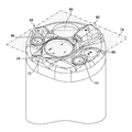
- FIG. 2 is an enlarged perspective view of the tip portion 22, and FIG. 3 is a front view of the tip portion 22 viewed from the longitudinal axis A (see FIG. 1) direction. Further, FIG. 4 is a cross-sectional view of the tip portion 22 along the IV-IV line of FIG.
- the tip portion 22 is made of a hard material such as metal, and is made of a tip portion main body 30 for holding various parts arranged on the tip portion 22 and an insulating resin material. It has a tip surface 30A of the main body 30 and a tip cover 32 that covers the tip outer peripheral surface 30B.
- the lens barrel 38 accommodating the observation window 34 and the optical system 36 constituting the observation unit and the fluid ejection nozzle 40 are connected.
- the tip portion 42A of the air supply / water supply channel 42 is shown.
- the configuration of the tip surface 28 of the tip portion 22 will be described with reference to FIGS. 2 and 3.
- the tip surface 28 is formed on the surface on the tip side of the tip cover 32.
- the tip surface 28 is formed based on a circular flat surface whose center C is the intersection with the longitudinal axis A.
- the "front side” refers to the tip side of the insertion portion 12 in the longitudinal axis A direction.
- the tip portion 22 is provided with a first surface 56 that constitutes a tip surface 28 along a plane substantially perpendicular to the longitudinal axis A of the insertion portion 12.
- the first surface 56 has a protruding portion 58 protruding forward from the first surface 56, and the second surface 62 is formed on the protruding portion 58.
- the first surface 56 is provided with a first illumination window 44, a second illumination window 46, a treatment tool outlet 48, and the like.
- the second surface 62 is provided with an observation window 34 for observing the inside of the subject.
- a step portion 64 is provided on the first surface 56, and a fluid ejection nozzle 40 is provided on the step portion 64.
- Reference numeral C shown in FIGS. 2 and 3 indicates the center of the tip surface 28.
- the first illumination window 44 and the second illumination window 46 are components of the illumination unit for illuminating the observed portion, and irradiate the observed portion with the illumination light sent from the above-mentioned light source device.
- the circular surfaces 44S and 46S of the first illumination window 44 and the second illumination window 46 are formed of, for example, flat surfaces and are arranged perpendicular to the longitudinal axis A.
- the centers of the surfaces 44S and 46S are arranged at positions deviated from the center C of the tip surface 28 to the peripheral edge of the tip surface 28, and face each other with the center B of the surface 34S of the observation window 34 interposed therebetween. Placed in position.
- the observation window 34 is a component of the observation unit for acquiring an image of the observed portion, and the subject light from the observed portion is taken into the imaging means via the optical system 36 shown in FIG.
- the image taken by this observation unit is sent to the above-mentioned processor device as an observation image.
- the circular surface 34S of the observation window 34 is formed by, for example, a flat surface, and is arranged perpendicular to the optical axis D of the observation window 34. Further, the surface 34S is arranged on the same surface as the second surface 62 as an example.
- the center B of the surface 34S is arranged at a position deviated from the center C of the tip surface 28 to the peripheral edge of the tip surface 28.
- the optical axis D of the observation window 34 is substantially parallel to the longitudinal axis A of the insertion portion 12, and the center B is located on the optical axis D.
- the treatment tool outlet 48 is communicated with the treatment tool introduction port 50 of the operation unit 14 via a treatment tool insertion channel (not shown) inserted inside the insertion unit 12 (see FIG. 1). Therefore, the treatment tool introduced from the treatment tool introduction port 50 is led out from the treatment tool outlet 48 via the treatment tool insertion channel described above.
- a suction channel (not shown) is connected to the above-mentioned treatment tool insertion channel, and the suction operation from the treatment tool outlet 48 causes the suction channel by operating the suction button 54 of the operation unit 14 (see FIG. 1). It is done through.
- the fluid ejection nozzle 40 has a base end portion 40A and a tip end portion 40B, and the shape including the base end portion 40A and the tip end portion 40B is formed in an L shape.
- the base end portion 40A is a portion connected to the tip end portion 42A of the air supply / water supply channel 42, and is connected to the above-mentioned air supply / water supply device via the air supply / water supply channel 42.
- the conduit 41A of the base end portion 40A has a circular cross section perpendicular to the axis of the conduit 41A, and the circular center E is the tip surface with respect to the center C (see FIG. 3) of the tip surface 28. It is arranged at a position deviated from the peripheral edge of 28, and is arranged at a position close to the first illumination window 44 of the first illumination window 44 and the second illumination window 46 in order to avoid interference with the treatment tool outlet 48.
- the conduit 41B of the tip portion 40B has a rectangular cross section perpendicular to the axis of the conduit 41B, and an injection port 52 opened toward the observation window 34 is formed at the tip of the conduit 41B. ..
- the injection port 52 is configured as a rectangular opening similar to the cross-sectional shape of the pipeline 41B.
- the air supply / water supply device can be used. Gas is injected from the injection port 52 toward the surface 34S of the observation window 34. Then, when the air supply / water supply button 55 is pressed with the finger closing the leak hole, the cleaning liquid from the air supply / water supply device is ejected from the injection port 52 toward the surface 34S of the observation window 34.
- a cleaning liquid is sprayed from the injection port 52 to remove deposits such as blood or body fluid adhering to the surface 34S of the observation window 34, and then gas is sprayed from the injection port 52.
- the cleaning liquid remaining on the surface 34S of the observation window 34 and the adjacent region adjacent to the observation window 34 is removed by spraying.
- the first surface 56 of the tip surface 28 has a first protective projection 66 and a second protective projection 68 in order to prevent the contacted member from coming into contact with the observation window 34.
- the projecting portion 58 has an extending portion 72 extending from the observation window 34 toward the side opposite to the fluid ejection nozzle 40.
- the extending portion 72 is provided so as to extend from the second surface 62 in parallel with the longitudinal direction A, and the surface 72A (see FIG. 4) of the extending portion 72 is formed flush with the second surface 62. Will be done.
- the first protective protrusion 66 and the second protective protrusion 68 are positioned so as to face each other with the virtual straight line 70 passing through the center B of the observation window 34 and the center F of the fluid ejection nozzle 40 interposed therebetween.
- the first protective projection 66 is arranged on the first surface 56 on the left side of FIG. 3
- the second protective projection 68 is arranged on the first surface 56 on the right side with the virtual straight line 70 as the boundary line.
- the first illumination window 44 and the second illumination window 46 are arranged at positions facing each other with the virtual straight line 70 in between, and the first protective projection 66 is arranged on the side where the first illumination window 44 is arranged.
- the second protective projection 68 is arranged on the side where the second illumination window 46 is arranged. Further, the top portions 66A and 68A of the first protective protrusion 66 and the second protective protrusion 68 are arranged inward from the outer edge portion of the first surface 56, respectively.
- the first protective projection 66 is provided at a position adjacent to the first illumination window 44.
- the second protective projection 68 is provided at a position adjacent to the second illumination window 46.
- the first protective projection 66 and the second protective projection 68 are arranged in a notched shape along the contours of the first illumination window 44 and the second illumination window 46, respectively.
- the first protective protrusion 66 and the second protective protrusion 68 have a notched shape so that the tip portion 22 does not become large.
- the first protective protrusion 66 and the second protective protrusion 68 can be arranged.
- FIG. 5 is a cross-sectional view of the tip portion 22 along the VV line of FIG. 2
- FIG. 6 is a cross-sectional view of the tip portion 22 along the VI-VI line of FIG.
- the height of each member arranged on the tip surface 28 of the tip portion 22 will be described with reference to FIGS. 5 and 6. This height refers to the length protruding from the reference position to the front side (the tip end side of the longitudinal axis A) with the position of the first surface 56 as the reference position.
- the optical systems of the observation window 34 and the first illumination window 44 are not shown.
- the height from the above reference position to the surface 34S of the observation window 34 and the height to the surface 72A of the extending portion 72 are H1, the first protective projection 66, and the second protective projection.
- the height H2 is set higher than the height H1. That is, the top portions 66A and 68A are arranged so as to project forward from the surface 34S.
- the height H3 is set higher than the height H2. That is, the tip side surface 43 is arranged so as to project forward from the tops 66A and 68A. That is, in the embodiment, the heights H1, H2, and H3 have a relationship of H1 ⁇ H2 ⁇ H3.
- FIG. 7 is a cross-sectional view illustrating the shapes of the first protective protrusion 66 and the second protective protrusion 68, which are parallel to the longitudinal axis A direction and include the top portions 66A and 68A.
- the first protective protrusion 66 and the second protective protrusion 68 have a rounded shape in a cross section perpendicular to the apex 66A, 68A and the longitudinal axis A direction, and are formed from the apex 66A, 68A. It has slopes 66B and 68B whose cross-sectional area increases toward the bottom 65 shown by the broken line. Further, the first protective protrusion 66 and the second protective protrusion 68 have a circular curved surface in a cross section parallel to the longitudinal axis A direction. As a result, the first protective protrusion 66 and the second protective protrusion 68 shown in FIG. 7 are formed in a spherical shape having a circular bottom portion 65.
- the slope portions 66B and 68B have a tangent line L at a point P where the bottom portion 65 of the first protective protrusion 66 and the second protective protrusion 68 and the first surface 56 meet in a cross section parallel to the longitudinal axis A direction.
- the angle ⁇ formed by the first surface 56 is larger than 90 °.
- the first protective protrusion 66 and the second protective protrusion 68 are configured such that the front side (the tip side in the longitudinal axis A direction) becomes thinner from the bottom portion 65 toward the top portions 66A and 68A.
- the fluid ejection nozzle 40 at least two of the fluid ejection nozzle 40, the first protective protrusion 66, the second protective protrusion 68, and the extension portion 72 provided so as to project from the first surface 56 toward the front side.
- the height (H1 ⁇ H2 ⁇ H3) and position of each member are set so that the virtual plane is arranged on the front side of the observation window 34. ..
- description will be made with reference to the virtual plane 74 shown in FIGS. 8 to 10.
- FIG. 8 shows the tip side surface 43 of the fluid ejection nozzle 40 (point Q in the figure), the top 66A of the first protective protrusion 66 (point R in the figure), and the top 68A of the second protective protrusion 68 (S in the figure). It is a figure which shows the state which the virtual plane 74 comes into contact with 3 points (points).
- the height H3 of the tip side surface 43 and the height H2 of the top 66A and the top 68A are higher than the height H1 of the surface 34S of the observation window 34. It is possible to prevent the contacted member shown as the virtual plane 74 from coming into contact with the observation window 34.
- the points R and S are arranged inside the outer edge portion of the first surface 56 when viewed from the front side in the longitudinal axis A direction, the size of the contacted member is smaller than the assumed size. Even in this case, it is possible to prevent the contacted member from coming into contact with the observation window 34.
- FIG. 9 shows the tip side surface 43 of the fluid ejection nozzle 40 (point Q in the figure), the top 68A of the second protective protrusion 68 (point S in the figure), and the surface 72A of the extension 72 (point T in the figure). ) Is a diagram showing a state in which the virtual plane 74 is in contact with the three points. As shown in FIGS.
- the height H3 of the tip side surface 43 and the height H2 of the top 68A are higher than the height H1 of the surface 34S of the observation window 34, so that the surface 72A of the extending portion 72 Even if the height H1 is the same as the height H1 of the surface 34S of the observation window 34, it is possible to prevent the contacted member shown as the virtual plane 74 from coming into contact with the observation window 34. Further, since the point S is arranged inside the outer edge portion of the first surface 56 when viewed from the front side in the longitudinal axis A direction, the size of the contacted member may be smaller than the expected size. Even if there is, it is possible to prevent the contacted member from coming into contact with the observation window 34.
- FIG. 10 shows the front end side surface 43 of the fluid ejection nozzle 40 (point Q in the figure), the top 66A of the first protective protrusion 66 (point R in the figure), and the surface 72A of the extension portion 72 (T in the figure). It is a figure which shows the state which the virtual plane 74 comes into contact with 3 points (points). As shown in FIGS.
- the height H3 of the tip side surface 43 and the height H2 of the top 66A are higher than the height H1 of the surface 34S of the observation window 34, so that the surface 72A of the extending portion 72 Even if the height H1 is the same as the height H1 of the surface 34S of the observation window 34, it is possible to prevent the contacted member shown as the virtual plane 74 from coming into contact with the observation window 34. Further, since the point R is arranged inside the outer edge portion of the first surface 56 when viewed from the front side in the longitudinal axis A direction, the size of the contacted member may be smaller than the expected size. Even if there is, it is possible to prevent the contacted member from coming into contact with the observation window 34.
- the tops 66A and 68A of the first protective protrusion 66 and the second protective protrusion 68 are the first surfaces 56.
- a virtual plane 74 that is arranged inside the outer edge portion of the above and is capable of contacting at least two of the fluid ejection nozzle 40, the first protective protrusion 66, the second protective protrusion 68, and the extension portion 72 from the front side.
- the virtual plane 74 is located on the front side of the observation window 34, so that the contacted member is placed on the observation window 34 even if the size of the contacted member is smaller than the expected size. Contact can be suppressed. Therefore, according to the endoscope 10 of the embodiment, it is possible to improve the protection of the observation window 34.
- the present invention is not limited to this.
- the fluid ejection nozzle 40, the first protective protrusion 66, and the second are also present.
- the same effect can be obtained even in a mode in which the virtual plane 74 is in contact with the four protective protrusions 68 and the extending portion 72.
- the same effect can be obtained even in a mode in which the virtual plane 74 is in contact with at least two of the fluid ejection nozzle 40, the first protective protrusion 66, the second protective protrusion 68, and the extending portion 72.
- the shapes of the first protective protrusion 66 and the second protective protrusion 68 are tapered from the bottom portion 65 toward the top portions 66A and 68A, and are formed of curved surfaces toward the top portions 66A and 68A. Therefore, it is possible to suppress the reflection of the first protective protrusion 66 and the second protective protrusion 68 within the range of the endoscopic observation field observed by the observation window 34.
- the above-mentioned endoscopic observation field of view refers to an image range displayed on a monitor (not shown) connected to a processor device. Further, it is preferable that the first protective projection 66 and the second protective projection 68 are arranged outside the viewing range of the observation window 34.
- the visual field range of the observation window 34 means a visual field range captured through the optical system of the observation window.
- the first protective protrusion 66 and the second protective protrusion 68 are illuminated by the illumination light from the first illumination window 44 and the second illumination window 46. Can be suppressed from blocking. As a result, the inside of the endoscopic field of view observed by the observation window 34 can be illuminated with the illumination light.
- first protective protrusion 66 and the second protective protrusion 68 into the above-mentioned shape, when cleaning the boundary portion between the outer peripheral portion of the bottom portion 65 and the first surface 56 using a cleaning tool such as a brush, Since the tip of the brush can easily reach the corner of the boundary, the cleanability of the tip surface 28 is improved.
- the shapes of the first protective protrusion 66 and the second protective protrusion 68 are formed so that the shape of the cross section perpendicular to the longitudinal axis A direction is rounded. As a result, it is possible to facilitate the flow of fluids such as cleaning liquid and gas ejected from the fluid ejection nozzle 40 along the slope portions 66B and 68B of the first protective projection 66 and the second protective projection 68, and the tip surface 28. It is possible to prevent the cleaning liquid from staying in the water.
- the first protective protrusion 66 and the second protective protrusion 68 are formed on the fluid ejection nozzle 40. Can be placed in close proximity. As a result, a fluid such as gas injected from the fluid ejection nozzle 40 can easily reach the first protective projection 66 and the second protective projection 68, and the cleaning liquid can be easily reached on the first protective projection 66 and the second protective projection 68. Even if the gas remains, it can be easily discharged by the gas injected from the fluid ejection nozzle 40.
- the fluid ejection nozzle 40 is provided on the step portion 64, but the present invention is not limited to this, and the fluid ejection nozzle 40 is provided on the first surface 56. You may.
- FIG. 11 is a cross-sectional view illustrating the shape of the first modification of the first protective protrusion 66 and the second protective protrusion 68, which is parallel to the longitudinal axis A direction and includes the tops 66A and 68A. ..
- the cross-sectional XIA is a cross-sectional view of the first protective projection 66 and the second protective projection 68 of the above-described embodiment (see FIG. 7), and the first protective projection 66 and the second protective projection 68 are composed of a part of a spherical surface.
- the slope portions 66B and 68B have a circular curved surface.
- the cross sections XIB and XIC are cross-sectional views of the first protective protrusion 66 and the second protective protrusion 68 of the first modification, and are composed of a part of an ellipsoid, and the slope portions 66B and 68B have an elliptical curved surface. doing.
- the cross section XIB has an elliptical major axis in the direction parallel to the first surface 56 and an elliptical minor axis in the vertical direction.
- the cross-section XIC has an elliptical major axis in the direction perpendicular to the first surface 56 and an elliptical minor axis in the direction parallel to the first surface 56.
- the shape of the cross section XIB makes it easier for the tip of the brush to enter the boundary between the outer peripheral portion of the bottom portion 65 of the first protective protrusion 66 and the second protective protrusion 68 and the first surface 56 as compared with the shape of the cross section XIA. It is possible to improve the cleanability of the tip surface 28.
- the first protective protrusion 66 and the second protective protrusion 68 of the first modification also satisfy the height relationship (H1 ⁇ H2 ⁇ H3) of each member, and the top portions 66A and 68A are inside the outer edge portion of the first surface 56.
- FIG. 12 is a cross-sectional view illustrating the shape of the second modification of the first protective protrusion 66 and the second protective protrusion 68, which is parallel to the longitudinal axis A direction and includes the tops 66A and 68A. .. As shown in FIG. 12, flat surfaces 67 are formed on the tops 66A and 68A. Further, the slope portions 66B and 68B are configured as slope portions 66B and 68B formed in a curved shape from the flat surface 67 toward the first surface 56. As shown in FIG.
- the curved slopes 66B and 68B have an angle ⁇ formed by the tangent M of the slopes 66B and 68B and the first surface 56 as the angle ⁇ from the tops 66A and 68A toward the bottom 65. It is formed in a curved shape so as to be close to 90 °.
- the center of the radius of curvature r1 of the curved slope portions 66B and 68B exists inside the first protective protrusion 66 and the second protective protrusion 68.
- the first protective protrusion 66 and the second protective protrusion 68 of the second modification also satisfy the height relationship (H1 ⁇ H2 ⁇ H3) of each member, and the top portions 66A and 68A are inside the outer edge portion of the first surface 56.
- FIG. 13 is a cross-sectional view illustrating the shape of the third modification of the first protective protrusion 66 and the second protective protrusion 68, which is parallel to the longitudinal axis A direction and includes the tops 66A and 68A. ..
- the first protective protrusion 66 and the second protective protrusion 68 of the third modification have the second point that the bottom 65 side of the slope portions 66B and 68B has straight slope portions 66C and 68C formed in a straight line. It is different from the first protective protrusion 66 and the second protective protrusion 68 of the modified example.
- the bottom 65 side of the first protective protrusion 66 and the second protective protrusion 68 of the third modification is formed in a conical shape.
- the curved slope portion and the straight slope portions 66C and 68C are smoothly connected.
- the first protective protrusion 66 and the second protective protrusion 68 of the third modification also satisfy the height relationship (H1 ⁇ H2 ⁇ H3) of each member, and the top portions 66A and 68A are inside the outer edge portion of the first surface 56.
- the tip of the brush can be easily inserted into the boundary between the outer peripheral portion of the bottom portion 65 of the first protective protrusion 66 and the second protective protrusion 68 and the first surface 56, thereby improving the cleanability of the tip surface 28. Can be done.
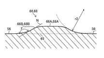
- FIG. 14 is a cross-sectional view illustrating the shape of the fourth modification of the first protective protrusion 66 and the second protective protrusion 68, which is parallel to the longitudinal axis A direction and includes the tops 66A and 68A. ..
- the first protective projection 66 and the second protective projection 68 of the fourth modification have a divergent shape from the tops 66A and 68A to the bottom 65
- the second modification and the second modification have a shape that expands toward the bottom 65. 3 It is formed so as to become gentler as it approaches the bottom 65 as compared with the first protective protrusion 66 and the second protective protrusion 68 of the modified example.
- the angle ⁇ formed by the tangents N of the slopes 66B and 68B of the first protective protrusion 66 and the second protective protrusion 68 and the first surface 56 increases from the tops 66A and 68A toward the bottom 65, It is formed in a curved shape so as to be close to 180 °.
- the center of the radius of curvature r2 of the curved slope portions 66B and 68B exists outside the first protective protrusion 66 and the second protective protrusion 68.
- the first protective protrusion 66 and the second protective protrusion 68 of the fourth modification also satisfy the height relationship (H1 ⁇ H2 ⁇ H3) of each member, and the top portions 66A and 68A are inside the outer edge portion of the first surface 56.
- H1 ⁇ H2 ⁇ H3 the height relationship of each member
- the top portions 66A and 68A are inside the outer edge portion of the first surface 56.
Abstract
観察窓の保護の向上を図ることができる内視鏡を提供する。内視鏡(10)の挿入部(12)の先端面(28)は、観察窓(34)と、流体噴出用ノズル(40)と、第1保護突起(66)と、第2保護突起(68)と、延出部(72)と、を有する。観察窓(34)及び延出部(72)は、第1面(56)から前方側に突出した突出部(58)に形成された第2面(62)に配置される。第1保護突起(66)及び第2保護突起(68)は、軸方向に垂直な断面形状が丸みをおびた形状であり、頂部(66A、68A)から底部に向かうにつれて断面積が大きくなる。頂部(66A、68A)は第1面56の外縁部より内側に配置される。流体噴出用ノズル(40)と第1保護突起(66)と、第2保護突起(68)と、延出部(72)とのうち、少なくとも2つに前方側から接触可能な仮想平面のすべての組み合わせにおいて、仮想平面が観察窓(34)より前方側に配置される。
Description
本発明は内視鏡に係り、特に挿入部の先端部における観察窓の保護の向上を図る内視鏡に関する。
例えば、胃内視鏡等の上部内視鏡においては、挿入部の細径化が求められている。このような内視鏡の挿入部の先端部における先端面には、被観察部位からの被写体光を取り込む観察窓、及び被観察部位に照明光を出射する照明窓が配置される。また、先端面には、観察窓に付着した体液等の付着物を除去するために観察窓に向けて洗浄液(水等)及び気体(空気等)の流体を噴射する流体噴出用ノズル(送気送水ノズル)が配置される。
内視鏡の先端面が、準備作業時において作業台の天板、検査時に術者が把持した際の床面、ハンガに掛けた際の床面、洗浄及び消毒の際のシンク及び洗浄機の槽等(以下、「被接触部材」ともいう)に接触した場合、観察窓及び照明窓が、上記の天板、床面及び槽に接触することで破損する虞がある。
観察窓のレンズ部分への接触を防止し、耐衝撃性を向上させた内視鏡として、例えば、下記の特許文献1には、挿入部の先端面に、第1保護突起、第2保護突起、及び、観察窓からノズルとは反対側に向かって延出する延出部と、を備えた内視鏡が記載されており、ノズル、第1保護突起、第2保護突起及び延出部により観察窓への接触を防止している。
しかしながら、特許文献1に記載の内視鏡は、上記の構成により観察窓に被接触部材が接触することを防止しているが、被接触部材の大きさが想定される大きさよりも小さい場合には、被接触部材が第1保護突起と第2保護突起とノズルと延出部とをすり抜けて観察窓に接触する場合がある。
本発明は、このような事情に鑑みてなされたものであり、観察窓の保護の向上を図ることができる内視鏡を提供することを目的とする。
本発明の目的を達成するために、本発明に係る内視鏡は、被検体内に挿入される挿入部と、挿入部の先端面を構成する第1面と、第1面から前方側に突出した突出部に形成された第2面と、第2面に設けられ、被検体内を観察するための観察窓と、第1面に設けられ、観察窓に向けて流体を噴出するノズルと、第1面に設けられ、観察窓の中心とノズルの中心とを通る仮想直線を挟んで配置された第1保護突起及び第2保護突起と、突出部に設けられ、観察窓からノズルとは反対側に向かって延出する延出部と、を備え、第1保護突起及び第2保護突起は、それぞれに頂部と、挿入部の軸方向に垂直な断面の形状が丸みをおびた形状であり、頂部から底部に向かうにつれて断面積が大きくなる斜面部と、を有し、頂部は、挿入部の軸方向前方側から見た場合に、第1面の外縁部より、内側に配置され、ノズルと、第1保護突起と、第2保護突起と、延出部とのうち少なくとも2つに前方側から接触可能な仮想平面のすべての組み合わせにおいて、仮想平面が観察窓よりも前方側に配置される。
本発明の一形態は、第1保護突起及び第2保護突起は、観察窓よりも前方側に突出して設けられていることが好ましい。
本発明の一形態は、ノズルは、第1保護突起及び第2保護突起よりも前方側に突出して設けられていることが好ましい。
本発明の一形態は、第1面に設けられ、仮想直線を挟んで配置された第1照明窓及び第2照明窓と、を有し、第1保護突起及び第2保護突起の少なくとも一方の保護突起は、仮想直線に対して、同じ側に配置された第1照明窓又は第2照明窓に隣接した位置に配置され、第1照明窓及び第2照明窓に隣接した第1保護突起及び第2保護突起は、隣接した第1照明窓又は第2照明窓の輪郭に沿って配置されることが好ましい。
本発明の一形態は、第1保護突起及び第2保護突起の少なくとも一方の保護突起は、頂部に平坦面を有し、平坦面は、斜面部と滑らかに接続されることが好ましい。
本発明の一形態は、第1保護突起及び第2保護突起の少なくとも一方の保護突起は、挿入部の軸方向に平行な断面において、第1面から前方側に向かって直線状に形成された円錐状の斜面を有することが好ましい。
本発明の一形態は、第1保護突起及び第2保護突起の少なくとも一方の保護突起は、挿入部の軸方向に平行な断面において、円状の曲面、又は、楕円状の曲面であることが好ましい。
本発明の一形態は、第1保護突起及び第2保護突起は、内視鏡観察視野範囲外に配置されることが好ましい。
本発明の一形態は、第1保護突起及び第2保護突起は、観察窓の視野範囲外に配置されることが好ましい。
本発明の一形態は、第1面に設けられ、前方側に突出した段部を有し、ノズルは、段部上に設けられていることが好ましい。
本発明によれば、観察窓の保護の向上を図ることができる。
以下、添付図面に従って本発明に係る内視鏡の好ましい実施形態について説明する。
図1は、本発明の実施形態に係る内視鏡10の全体図である。
図1に示すように、内視鏡10は、被検体内に挿入される挿入部12と、挿入部12の基端に設けられた操作部14と、内視鏡10を不図示の光源装置、プロセッサ装置及び送気送水装置等のシステム構成機器に接続するユニバーサルケーブル16と、を備えている。
挿入部12は、先端と基端と挿入部12の軸である長手軸Aとを有し、基端から先端に向って順に軟性部18、湾曲部20及び先端部22を備えている。
軟性部18は、可撓性を有し、挿入部12の挿入経路に沿って任意の方向に湾曲可能である。湾曲部20は、操作部14に回動自在に設けられたアングルノブ24、26を操作することにより上下方向と左右方向のそれぞれに湾曲され、先端部22が向く方向を任意の方向に変更可能である。また、先端部22は、挿入部12の先端に設けられた先端面28(図2参照)を有している。
図2は、先端部22を拡大して示した斜視図であり、図3は、先端部22を長手軸A(図1参照)方向から正面視した正面図である。また、図4は、図2のIV-IV線に沿う先端部22の断面図である。
図4に示すように、先端部22は、金属等の硬質材料により構成され、先端部22に配置される各種部品を保持する先端部本体30と、絶縁性の樹脂材料により構成され、先端部本体30の先端面30Aと先端外周面30Bを被覆する先端カバー32と、を有している。なお、図4には、先端部本体30及び先端カバー32に保持される部品として、観察部を構成する観察窓34及び光学系36を収容した鏡胴38と、流体噴出用ノズル40に接続される送気送水チャンネル42の先端部分42Aとが示されている。
図2及び図3を用いて、先端部22の先端面28の構成を説明する。先端面28は先端カバー32の先端側の面に形成される。先端面28は、長手軸Aとの交差位置を先端面28の中心Cとする円形状の平坦面を基調にして形成される。なお、以下の説明において、「前方側」とは、挿入部12の長手軸A方向の先端側を言う。
図2及び図3に示すように先端部22には、挿入部12の長手軸Aに対して略垂直な平面に沿った先端面28を構成する第1面56が設けられる。第1面56には、第1面56から前方側に突出した突出部58を有し、突出部58に第2面62が形成される。
第1面56には、第1照明窓44、第2照明窓46及び処置具導出口48等が設けられている。第2面62には、被検体内を観察する観察窓34が設けられている。第1面56には、段部64が設けられており、段部64上に、流体噴出用ノズル40が設けられている。なお、図2及び図3に示した符号Cは、先端面28の中心を示している。
第1照明窓44及び第2照明窓46は、被観察部位を照明するための照明部の構成要素であり、上記の光源装置から送られてきた照明光を被観察部位に照射する。
第1照明窓44及び第2照明窓46の円形の表面44S、46Sは、例えば、平坦面により形成され、長手軸Aと垂直に配置される。そして、表面44S、46Sの各々の中心は、先端面28の中心Cに対して先端面28の周縁に偏倚した位置に配置され、且つ観察窓34の表面34Sの中心Bを挟んで互いに対向した位置に配置される。
観察窓34は、被観察部位の画像を取得するための観察部の構成要素であり、被観察部位からの被写体光を、図4に示した光学系36を介して撮像手段に取り込む。この観察部によって撮影された画像は、観察画像として上記のプロセッサ装置に送られる。
観察窓34の円形の表面34Sは、例えば、平坦面により形成され、観察窓34の光軸Dと垂直に配置される。また、表面34Sは一例として、第2面62と同一面上に配置されている。そして、表面34Sの中心Bは、先端面28の中心Cに対して先端面28の周縁に偏倚した位置に配置される。観察窓34の光軸Dは、挿入部12の長手軸Aと略平行であり、光軸D上に中心Bが位置している。
処置具導出口48は、挿入部12(図1参照)の内部に挿通された処置具挿通チャンネル(不図示)を介して操作部14の処置具導入口50に連通される。したがって、処置具導入口50から導入された処置具は、上記の処置具挿通チャンネルを介して処置具導出口48から導出される。
また、上記の処置具挿通チャンネルには吸引チャンネル(不図示)が連結されており、操作部14(図1参照)の吸引ボタン54の操作により処置具導出口48からの吸引動作が吸引チャンネルを介して行われる。
流体噴出用ノズル40は、図4に示すように、基端部分40Aと先端部分40Bとを有し、基端部分40Aと先端部分40Bとを含む形状がL字状に構成されている。
基端部分40Aは、送気送水チャンネル42の先端部分42Aに接続される部分であり、送気送水チャンネル42を介して上記の送気送水装置に接続される。また、基端部分40Aの管路41Aは、管路41Aの軸線に垂直な断面が円形に形成され、その円形の中心Eは、先端面28の中心C(図3参照)に対して先端面28の周縁に偏倚した位置に配置され、且つ処置具導出口48との干渉を避けるため第1照明窓44及び第2照明窓46のうちの第1照明窓44に近い位置に配置される。
先端部分40Bの管路41Bは、管路41Bの軸線に垂直な断面が長方形に形成され、その管路41Bの先端には、観察窓34に向けて開口された噴射口52が形成されている。この噴射口52は、管路41Bの断面形状と同様に長方形の開口として構成されている。
このように構成された流体噴出用ノズル40によれば、操作部14(図1参照)の送気送水ボタン55に形成されたリーク孔(不図示)を指で閉鎖すると、送気送水装置からの気体が噴射口52から観察窓34の表面34Sに向けて噴射される。そして、上記のリーク孔を閉鎖した指で送気送水ボタン55を押下すると、送気送水装置からの洗浄液が噴射口52から観察窓34の表面34Sに向けて噴射される。なお、観察窓34の洗浄の手順としては、例えば、噴射口52から洗浄液を噴射して観察窓34の表面34Sに付着した血液又は体液等の付着物を除去した後、噴射口52から気体を噴射して観察窓34の表面34S及び観察窓34に隣接した隣接領域に残留した洗浄液を除去する。
本実施形態では、上述した構成に加え、更に、先端面28の第1面56は、観察窓34への被接触部材の接触を防止するため、第1保護突起66及び第2保護突起68を備える。また、突出部58には、観察窓34から流体噴出用ノズル40とは反対側に向かって延出する延出部72を有する。延出部72は、第2面62から長手軸Aの垂直方向に平行に伸びて設けられており、延出部72の表面72A(図4参照)は第2面62と面一上に形成される。
図3に示すように、第1保護突起66及び第2保護突起68は、観察窓34の中心Bと流体噴出用ノズル40の中心Fとを通る仮想直線70を挟んで、互いに対向する位置に配置されている。換言すれば、仮想直線70を境界線として、第1保護突起66は、図3の左側の第1面56に配置され、第2保護突起68は、右側の第1面56に配置される。同様に第1照明窓44及び第2照明窓46は、仮想直線70を挟んで、互いに対向する位置に配置されており、第1照明窓44が配置される側に第1保護突起66が配置され、第2照明窓46が配置される側に第2保護突起68が配置されている。また、第1保護突起66及び第2保護突起68のそれぞれの頂部66A、68Aは、第1面56の外縁部から内側に配置される。
図2及び図3に示す先端面28においては、第1保護突起66は、第1照明窓44に隣接した位置に設けられる。また、第2保護突起68は、第2照明窓46に隣接した位置に設けられる。第1保護突起66及び第2保護突起68は、それぞれが第1照明窓44及び第2照明窓46の輪郭に沿って、切り欠かれた形状で配置されている。
ここで、上部内視鏡においては、内視鏡10を挿入する際の被検体への負担を軽減するために、挿入部12の細径化もしくは小型化が求められている。したがって、先端面28に配置される部材の位置が制限されるため、第1保護突起66及び第2保護突起68を切り欠かれた形状とすることにより、先端部22を大型化することなく、第1保護突起66及び第2保護突起68を配置することができる。
図5は、図2のV-V線に沿う先端部22の断面図であり、図6は、図2のVI-VI線に沿う先端部22の断面図である。図5及び図6を参照して、先端部22の先端面28に配置された各部材の高さについて説明する。この高さとは、第1面56の位置を基準位置とし、この基準位置から前方側(長手軸Aの先端側)に突出した長さを指す。なお、図5及び図6においては、説明の便宜上、観察窓34及び第1照明窓44のそれぞれの光学系は図示を省略している。
図5及び図6に示すように、上記の基準位置から観察窓34の表面34Sまでの高さ及び延出部72の表面72Aまでの高さをH1、第1保護突起66及び第2保護突起68の頂部66A、68Aまでの高さをH2した場合、高さH2は、高さH1よりも高めに設定されている。すなわち、頂部66A、68Aは、表面34Sよりも前方側に突出して配置されている。また、上記の基準位置から流体噴出用ノズル40の先端側面43までの高さをH3とした場合、高さH3は、高さH2よりも高めに設定されている。すなわち、先端側面43は、頂部66A、68Aよりも前方側に突出して配置されている。つまり、実施形態において各高さH1、H2、H3は、H1<H2<H3の関係にある。
上記の高さ関係により、(1)から(5)の場合に、被接触部材の観察窓34への接触を防止することができる。すなわち、長手軸Aの前方側から被接触部材(不図示)が、(1)流体噴出用ノズル40の先端側面43と延出部72の表面72Aの2つに接触した場合、(2)流体噴出用ノズル40の先端側面43と第1保護突起66の頂部66Aの2つに被接触部材が接触した場合、(3)流体噴出用ノズル40の先端側面43と第2保護突起68の頂部68Aの2つに被接触部材が接触した場合、(3)第1保護突起66の頂部66Aと第2保護突起68の頂部68Aの2つに被接触部材が接触した場合、(4)第1保護突起66の頂部66Aと延出部72の表面72Aの2つに被接触部材が接触した場合、(5)第2保護突起68の頂部68Aと延出部72の表面72Aの2つに被接触部材が接触した場合において、それぞれの場合に、被接触部材が観察窓34に接触することを防止することができる。なお、この内容については後述する。
次に、図7を参照して、第1保護突起66及び第2保護突起68の形状の一例について説明する。図7は、第1保護突起66及び第2保護突起68の形状を説明する断面図であって、長手軸A方向に平行であって頂部66A、68Aを含む断面図である。
図7に示すように、第1保護突起66及び第2保護突起68は、頂部66A、68Aと、長手軸A方向に垂直な断面の形状が丸みをおびた形状であり、頂部66A、68Aから破線で示す底部65に向かうにつれて断面積が大きくなる斜面部66B、68Bと、を有する。また、第1保護突起66及び第2保護突起68は、長手軸A方向に平行な断面において、円状の曲面を有している。これにより、図7に示す第1保護突起66及び第2保護突起68は、円形の底部65を有する球面状に構成されている。
具体的に説明すると、斜面部66B、68Bは、長手軸A方向に平行な断面において、第1保護突起66及び第2保護突起68の底部65と第1面56が接する点Pの接線Lと第1面56とのなす角度αが90°より大きい角で構成される。これにより、第1保護突起66及び第2保護突起68は、底部65から頂部66A、68Aに向かうにつれて前方側(長手軸A方向の先端側)が細くなる形状に構成されている。
本実施形態においては、第1面56から前方側に向かって突出して設けられた流体噴出用ノズル40、第1保護突起66、第2保護突起68及び延出部72のうち、少なくとも2つに前方側から接触可能な仮想平面のすべての組み合わせにおいて、仮想平面が、観察窓34より前方側に配置されるように、各部材の高さ(H1<H2<H3)と位置が設定されている。以下、図8から図10に示した仮想平面74を参照して説明する。
図8は、流体噴出用ノズル40の先端側面43(図中Qの点)、第1保護突起66の頂部66A(図中Rの点)、及び第2保護突起68の頂部68A(図中Sの点)の3点に仮想平面74が接触する状態を示す図である。ここで、図5及び図6に示したように、先端側面43の高さH3と、頂部66A及び頂部68Aの高さH2とは、観察窓34の表面34Sの高さH1よりも高いので、仮想平面74として示される被接触部材が観察窓34に接触することを防止することができる。また、点R、Sは長手軸A方向の前方側から見た場合に、第1面56の外縁部より内側に配置されているので、被接触部材の大きさが想定される大きさよりも小さい場合であっても、被接触部材が観察窓34に接触することを抑制することができる。
図9は、流体噴出用ノズル40の先端側面43(図中Qの点)、第2保護突起68の頂部68A(図中Sの点)、延出部72の表面72A(図中Tの点)の3点に仮想平面74が接触する状態を示す図である。図5及び図6に示したように、先端側面43の高さH3及び頂部68Aの高さH2は、観察窓34の表面34Sの高さH1よりも高いので、延出部72の表面72Aの高さH1が観察窓34の表面34Sの高さH1と同じであっても、仮想平面74として示される被接触部材が観察窓34に接触することを防止することができる。また、点Sは長手軸A方向の前方側から見た場合に、第1面56の外縁部より内側に配置されているので、被接触部材の大きさが想定される大きさよりも小さい場合であっても、被接触部材が観察窓34に接触することを抑制することができる。
図10は、流体噴出用ノズル40の先端側面43(図中Qの点)、第1保護突起66の頂部66A(図中Rの点)、及び、延出部72の表面72A(図中Tの点)の3点に仮想平面74が接触する状態を示す図である。図5及び図6に示したように、先端側面43の高さH3及び頂部66Aの高さH2は、観察窓34の表面34Sの高さH1よりも高いので、延出部72の表面72Aの高さH1が観察窓34の表面34Sの高さH1と同じであっても、仮想平面74として示される被接触部材が観察窓34に接触することを防止することができる。また、点Rは長手軸A方向の前方側から見た場合に、第1面56の外縁部より内側に配置されているので、被接触部材の大きさが想定される大きさよりも小さい場合であっても、被接触部材が観察窓34に接触することを抑制することができる。
このように実施形態の内視鏡10は、第1保護突起66及び第2保護突起68の頂部66A、68Aを長手軸A方向前方側から見た場合に、頂部66A、68Aを第1面56の外縁部より内側に配置し、流体噴出用ノズル40、第1保護突起66と、第2保護突起68と、延出部72とのうち少なくとも2つに前方側から接触可能な仮想平面74のすべての組み合わせにおいて、仮想平面74が観察窓34よりも前方側に配置されるので、被接触部材の大きさが想定される大きさよりも小さい場合であっても、被接触部材が観察窓34に接触することを抑制することができる。したがって、実施形態の内視鏡10によれば、観察窓34の保護の向上を図ることができる。
上記の図8から図10では、流体噴出用ノズル40を含む3つに仮想平面74が接触する態様を説明したが、これに限定されるものではない。例えば、第1保護突起66、第2保護突起68及び延出部72の3つに仮想平面74が接触する態様であっても、また、流体噴出用ノズル40、第1保護突起66、第2保護突起68及び延出部72の4つに仮想平面74が接触する態様であっても同様の効果を得ることができる。更に、流体噴出用ノズル40、第1保護突起66、第2保護突起68及び延出部72のうち少なくとも2つに仮想平面74が接触する態様であっても同様の効果を得ることができる。
また、図7に示したように、第1保護突起66及び第2保護突起68の形状は、底部65から頂部66A、68Aに向かって細くなっており、頂部66A、68Aに向かって曲面で構成されているので、観察窓34で観察される内視鏡観察視野範囲内に第1保護突起66及び第2保護突起68が映り込むことを抑制することができる。上記の内視鏡観察視野範囲とは、プロセッサ装置に接続されたモニタ(不図示)に映し出される画像範囲を指す。さらに、第1保護突起66及び第2保護突起68は、観察窓34の視野範囲外に配置することが好ましい。観察窓34の視野範囲とは、観察窓の光学系を介して取り込まれる視野範囲を意味する。
また、第1保護突起66及び第2保護突起68を上記の形状とすることで、第1保護突起66及び第2保護突起68が、第1照明窓44及び第2照明窓46からの照明光を遮ることを抑制することができる。これにより、観察窓34で観察される内視鏡視野範囲内を照明光で照らすことができる。
また、第1保護突起66及び第2保護突起68を上記の形状とすることにより、底部65の外周部と第1面56との境界部をブラシなどの洗浄器具を用いて洗浄する際に、ブラシの先端が境界部の隅の部分まで入り易くなるので、先端面28の洗浄性が向上する。
また、第1保護突起66及び第2保護突起68の形状は、長手軸A方向に垂直な断面の形状が丸みをおびた形状で形成されている。これにより、第1保護突起66及び第2保護突起68の斜面部66B、68Bに沿って、流体噴出用ノズル40から噴射される洗浄液及び気体等の流体を流し易くすることができ、先端面28に洗浄液がとどまることを抑制することができる。さらに、第1保護突起66及び第2保護突起68の頂部66A、68Aを第1面56の外縁部より内側にすることで、流体噴出用ノズル40に第1保護突起66及び第2保護突起68を近接配置することができる。これにより、流体噴出用ノズル40から噴射される気体等の流体を第1保護突起66及び第2保護突起68に届きや易くすることができ、第1保護突起66及び第2保護突起68に洗浄液が残っていたとしても、流体噴出用ノズル40から噴射される気体により排出し易くすることができる。
なお、上記実施形態では、流体噴出用ノズル40が段部64上に設けられた構成を示したが、これに限らず、第1面56上に流体噴出用ノズル40が設けられた構成であってもよい。
以上、本発明に係る内視鏡について説明したが、本発明は、上記の例には限定されず、本発明の要旨を逸脱しない範囲において、いくつかの改良又は変形を行ってもよい。以下、図面に従って変形例について説明する。
〔第1変形例〕
図11は、第1保護突起66及び第2保護突起68の第1変形例の形状を説明する断面図であって、長手軸A方向に平行であって頂部66A、68Aを含む断面図である。断面XIAは、上述した実施形態(図7参照)の第1保護突起66及び第2保護突起68の断面図であり、第1保護突起66及び第2保護突起68は球状の一部により構成され、斜面部66B、68Bは円状の曲面を有している。断面XIB、XICは、第1変形例の第1保護突起66及び第2保護突起68の断面図であり、楕円体の一部により構成され、斜面部66B、68Bは、楕円状の曲面を有している。断面XIBは、第1面56に平行な方向に楕円形の長軸を有し、垂直な方向に楕円形の短軸を有している。断面XICは、第1面56に垂直な方向に楕円形の長軸を有し、平行な方向に楕円形の短軸を有している。断面XIBの形状は、断面XIAの形状に比べて、第1保護突起66及び第2保護突起68の底部65の外周部と第1面56との境界部にブラシの先端を入り易くすることができ、先端面28の洗浄性を向上させることができる。第1変形例の第1保護突起66及び第2保護突起68においても、各部材の高さの関係(H1<H2<H3)を満たし、頂部66A、68Aを第1面56の外縁部より内側に配置することで、被接触部材が観察窓34に接触することを抑制することができる。
図11は、第1保護突起66及び第2保護突起68の第1変形例の形状を説明する断面図であって、長手軸A方向に平行であって頂部66A、68Aを含む断面図である。断面XIAは、上述した実施形態(図7参照)の第1保護突起66及び第2保護突起68の断面図であり、第1保護突起66及び第2保護突起68は球状の一部により構成され、斜面部66B、68Bは円状の曲面を有している。断面XIB、XICは、第1変形例の第1保護突起66及び第2保護突起68の断面図であり、楕円体の一部により構成され、斜面部66B、68Bは、楕円状の曲面を有している。断面XIBは、第1面56に平行な方向に楕円形の長軸を有し、垂直な方向に楕円形の短軸を有している。断面XICは、第1面56に垂直な方向に楕円形の長軸を有し、平行な方向に楕円形の短軸を有している。断面XIBの形状は、断面XIAの形状に比べて、第1保護突起66及び第2保護突起68の底部65の外周部と第1面56との境界部にブラシの先端を入り易くすることができ、先端面28の洗浄性を向上させることができる。第1変形例の第1保護突起66及び第2保護突起68においても、各部材の高さの関係(H1<H2<H3)を満たし、頂部66A、68Aを第1面56の外縁部より内側に配置することで、被接触部材が観察窓34に接触することを抑制することができる。
[第2変形例]
図12は、第1保護突起66及び第2保護突起68の第2変形例の形状を説明する断面図であって、長手軸A方向に平行であって頂部66A、68Aを含む断面図である。図12に示すように、頂部66A、68Aには平坦面67が形成されている。また、斜面部66B、68Bは、平坦面67から第1面56に向かって曲線状に形成された斜面部66B、68Bとして構成されている。曲線状の斜面部66B、68Bは、図12に示すように、斜面部66B、68Bの接線Mと第1面56とのなす角βの角度が、頂部66A、68Aから底部65に向かうにつれて、90°に近くなるように曲線状に形成されている。このような曲線状の斜面部66B、68Bの曲率半径r1の中心は、第1保護突起66及び第2保護突起68の内側に存在する。第2変形例の第1保護突起66及び第2保護突起68においても、各部材の高さの関係(H1<H2<H3)を満たし、頂部66A、68Aを第1面56の外縁部より内側に配置することで、被接触部材が観察窓34に接触することを抑制することができる。
図12は、第1保護突起66及び第2保護突起68の第2変形例の形状を説明する断面図であって、長手軸A方向に平行であって頂部66A、68Aを含む断面図である。図12に示すように、頂部66A、68Aには平坦面67が形成されている。また、斜面部66B、68Bは、平坦面67から第1面56に向かって曲線状に形成された斜面部66B、68Bとして構成されている。曲線状の斜面部66B、68Bは、図12に示すように、斜面部66B、68Bの接線Mと第1面56とのなす角βの角度が、頂部66A、68Aから底部65に向かうにつれて、90°に近くなるように曲線状に形成されている。このような曲線状の斜面部66B、68Bの曲率半径r1の中心は、第1保護突起66及び第2保護突起68の内側に存在する。第2変形例の第1保護突起66及び第2保護突起68においても、各部材の高さの関係(H1<H2<H3)を満たし、頂部66A、68Aを第1面56の外縁部より内側に配置することで、被接触部材が観察窓34に接触することを抑制することができる。
[第3変形例]
図13は、第1保護突起66及び第2保護突起68の第3変形例の形状を説明する断面図であって、長手軸A方向に平行であって頂部66A、68Aを含む断面図である。第3変形例の第1保護突起66及び第2保護突起68は、斜面部66B、68Bの底部65側が、直線状に形成された直線斜面部66C、68Cを有している点が、第2変形例の第1保護突起66及び第2保護突起68と異なっている。すなわち、第3変形例の第1保護突起66及び第2保護突起68の底部65側は円錐状に形成されている。この場合、曲線状の斜面部と直線斜面部66C、68Cは、滑らかに接続される。第3変形例の第1保護突起66及び第2保護突起68においても、各部材の高さの関係(H1<H2<H3)を満たし、頂部66A、68Aを第1面56の外縁部より内側に配置することで、被接触部材が観察窓34に接触することを抑制することができる。また、第1保護突起66及び第2保護突起68の底部65の外周部と第1面56との境界部にブラシの先端を入り易くすることができ、先端面28の洗浄性を向上させることができる。
図13は、第1保護突起66及び第2保護突起68の第3変形例の形状を説明する断面図であって、長手軸A方向に平行であって頂部66A、68Aを含む断面図である。第3変形例の第1保護突起66及び第2保護突起68は、斜面部66B、68Bの底部65側が、直線状に形成された直線斜面部66C、68Cを有している点が、第2変形例の第1保護突起66及び第2保護突起68と異なっている。すなわち、第3変形例の第1保護突起66及び第2保護突起68の底部65側は円錐状に形成されている。この場合、曲線状の斜面部と直線斜面部66C、68Cは、滑らかに接続される。第3変形例の第1保護突起66及び第2保護突起68においても、各部材の高さの関係(H1<H2<H3)を満たし、頂部66A、68Aを第1面56の外縁部より内側に配置することで、被接触部材が観察窓34に接触することを抑制することができる。また、第1保護突起66及び第2保護突起68の底部65の外周部と第1面56との境界部にブラシの先端を入り易くすることができ、先端面28の洗浄性を向上させることができる。
[第4変形例]
図14は、第1保護突起66及び第2保護突起68の第4変形例の形状を説明する断面図であって、長手軸A方向に平行であって頂部66A、68Aを含む断面図である。第4変形例の第1保護突起66及び第2保護突起68は、図14に示すように、頂部66A、68Aから底部65に行くにつれて、末広がりの形状となっており、第2変形例及び第3変形例の第1保護突起66及び第2保護突起68に比べて底部65に近づくにつれて、なだらかになるように形成されている。具体的には、第1保護突起66及び第2保護突起68の斜面部66B、68Bの接線Nと第1面56とのなす角γの角度が、頂部66A、68Aから底部65に向かうにつれて、180°に近くなるように曲線状に形成されている。このような曲線状の斜面部66B、68Bの曲率半径r2の中心は、第1保護突起66及び第2保護突起68の外側に存在する。第4変形例の第1保護突起66及び第2保護突起68においても、各部材の高さの関係(H1<H2<H3)を満たし、頂部66A、68Aを第1面56の外縁部より内側に配置することで、被接触部材が観察窓34に接触することを抑制することができる。また、第1保護突起66及び第2保護突起68の底部65の外周部と第1面56との境界部にブラシの先端を入り易くすることができ、先端面28の洗浄性を向上させることができる。
図14は、第1保護突起66及び第2保護突起68の第4変形例の形状を説明する断面図であって、長手軸A方向に平行であって頂部66A、68Aを含む断面図である。第4変形例の第1保護突起66及び第2保護突起68は、図14に示すように、頂部66A、68Aから底部65に行くにつれて、末広がりの形状となっており、第2変形例及び第3変形例の第1保護突起66及び第2保護突起68に比べて底部65に近づくにつれて、なだらかになるように形成されている。具体的には、第1保護突起66及び第2保護突起68の斜面部66B、68Bの接線Nと第1面56とのなす角γの角度が、頂部66A、68Aから底部65に向かうにつれて、180°に近くなるように曲線状に形成されている。このような曲線状の斜面部66B、68Bの曲率半径r2の中心は、第1保護突起66及び第2保護突起68の外側に存在する。第4変形例の第1保護突起66及び第2保護突起68においても、各部材の高さの関係(H1<H2<H3)を満たし、頂部66A、68Aを第1面56の外縁部より内側に配置することで、被接触部材が観察窓34に接触することを抑制することができる。また、第1保護突起66及び第2保護突起68の底部65の外周部と第1面56との境界部にブラシの先端を入り易くすることができ、先端面28の洗浄性を向上させることができる。
10 内視鏡
12 挿入部
14 操作部
16 ユニバーサルケーブル
18 軟性部
20 湾曲部
22 先端部
24、26 アングルノブ
28 先端面
30 先端部本体
30A 先端部本体の先端面
30B 先端部本体の先端外周面
32 先端カバー
34 観察窓
34S 観察窓の表面
36 光学系
38 鏡胴
40 流体噴出用ノズル
40A 基端部分
40B 先端部分
41A 基端部分の管路
41B 先端部分の管路
42 送気送水チャンネル
42A 送気送水チャンネルの先端部分
43 先端側面
44 第1照明窓
46 第2照明窓
44S 第1照明窓の表面
46S 第2照明窓の表面
48 処置具導出口
52 噴射口
54 吸引ボタン
55 送気送水ボタン
56 第1面
58 突出部
62 第2面
64 段部
65 底部
66 第1保護突起
66A 頂部
66B 斜面部
66C 直線斜面部
67 平坦面
68 第2保護突起
68A 頂部
68B 斜面部
68C 直線斜面部
70 仮想直線
72 延出部
74 仮想平面
A 長手軸
B 観察窓の表面の中心
C 先端面の中心
D 観察窓の光軸
E 送気送水チャンネルの基端部分の中心
F 流体噴出用ノズルの中心
L、M、N 接線
P 底部と第1面が接する点
Claims (10)
- 被検体内に挿入される挿入部と、
前記挿入部の先端面を構成する第1面と、
前記第1面から前方側に突出した突出部に形成された第2面と、
前記第2面に設けられ、被検体内を観察するための観察窓と、
前記第1面に設けられ、前記観察窓に向けて流体を噴出するノズルと、
前記第1面に設けられ、前記観察窓の中心と前記ノズルの中心とを通る仮想直線を挟んで配置された第1保護突起及び第2保護突起と、
前記突出部に設けられ、前記観察窓から前記ノズルとは反対側に向かって延出する延出部と、を備え、
前記第1保護突起及び前記第2保護突起は、それぞれに頂部と、前記挿入部の軸方向に垂直な断面の形状が丸みをおびた形状であり、前記頂部から底部に向かうにつれて断面積が大きくなる斜面部と、を有し、
前記頂部は、前記挿入部の軸方向前方側から見た場合に、前記第1面の外縁部より、内側に配置され、
前記ノズルと、前記第1保護突起と、前記第2保護突起と、前記延出部とのうち少なくとも2つに前方側から接触可能な仮想平面のすべての組み合わせにおいて、前記仮想平面が前記観察窓よりも前方側に配置される、
内視鏡。 - 前記第1保護突起及び前記第2保護突起は、前記観察窓よりも前方側に突出して設けられている、
請求項1に記載の内視鏡。 - 前記ノズルは、第1保護突起及び前記第2保護突起よりも前方側に突出して設けられている、
請求項1又は2に記載の内視鏡。 - 前記第1面に設けられ、前記仮想直線を挟んで配置された第1照明窓及び第2照明窓と、を有し、
前記第1保護突起及び前記第2保護突起の少なくとも一方の保護突起は、前記仮想直線に対して、同じ側に配置された前記第1照明窓又は前記第2照明窓に隣接した位置に配置され、
前記第1照明窓及び前記第2照明窓に隣接した前記第1保護突起及び前記第2保護突起は、隣接した前記第1照明窓又は前記第2照明窓の輪郭に沿って配置される、
請求項1から3のいずれか1項に記載の内視鏡。 - 前記第1保護突起及び第2保護突起の少なくとも一方の保護突起は、前記頂部に平坦面を有し、
前記平坦面は、前記斜面部と滑らかに接続される、
請求項1から4のいずれか1項に記載の内視鏡。 - 前記第1保護突起及び第2保護突起の少なくとも一方の保護突起は、前記挿入部の軸方向に平行な断面において、前記第1面から前方側に向かって直線状に形成された円錐状の斜面を有する、
請求項1から5のいずれか1項に記載の内視鏡。 - 前記第1保護突起及び第2保護突起の少なくとも一方の保護突起は、前記挿入部の軸方向に平行な断面において、円状の曲面、又は、楕円状の曲面である、
請求項1から6のいずれか1項に記載の内視鏡。 - 前記第1保護突起及び前記第2保護突起は、内視鏡観察視野範囲外に配置される、
請求項1から7のいずれか1項に記載の内視鏡。 - 前記第1保護突起及び前記第2保護突起は、前記観察窓の視野範囲外に配置される、
請求項8に記載の内視鏡。 - 前記第1面に設けられ、前方側に突出した段部を有し、
前記ノズルは、前記段部上に設けられている、
請求項1から9のいずれか1項に記載の内視鏡。
Priority Applications (2)
| Application Number | Priority Date | Filing Date | Title |
|---|---|---|---|
| CN202080080040.5A CN114727747A (zh) | 2019-11-29 | 2020-11-24 | 内窥镜 |
| JP2021561398A JP7216226B2 (ja) | 2019-11-29 | 2020-11-24 | 内視鏡 |
Applications Claiming Priority (2)
| Application Number | Priority Date | Filing Date | Title |
|---|---|---|---|
| JP2019217203 | 2019-11-29 | ||
| JP2019-217203 | 2019-11-29 |
Publications (1)
| Publication Number | Publication Date |
|---|---|
| WO2021106831A1 true WO2021106831A1 (ja) | 2021-06-03 |
Family
ID=76130468
Family Applications (1)
| Application Number | Title | Priority Date | Filing Date |
|---|---|---|---|
| PCT/JP2020/043572 WO2021106831A1 (ja) | 2019-11-29 | 2020-11-24 | 内視鏡 |
Country Status (3)
| Country | Link |
|---|---|
| JP (1) | JP7216226B2 (ja) |
| CN (1) | CN114727747A (ja) |
| WO (1) | WO2021106831A1 (ja) |
Families Citing this family (1)
| Publication number | Priority date | Publication date | Assignee | Title |
|---|---|---|---|---|
| JP7312931B2 (ja) | 2016-09-28 | 2023-07-24 | 東特塗料株式会社 | 電気絶縁電線 |
Citations (4)
| Publication number | Priority date | Publication date | Assignee | Title |
|---|---|---|---|---|
| JPS58160001U (ja) * | 1982-04-19 | 1983-10-25 | 旭光学工業株式会社 | 内視鏡 |
| JPH10192225A (ja) * | 1997-01-13 | 1998-07-28 | Asahi Optical Co Ltd | 内視鏡の先端部 |
| JP2019058203A (ja) * | 2017-09-22 | 2019-04-18 | 富士フイルム株式会社 | 内視鏡 |
| JP2019062988A (ja) * | 2017-09-28 | 2019-04-25 | 富士フイルム株式会社 | 内視鏡 |
-
2020
- 2020-11-24 CN CN202080080040.5A patent/CN114727747A/zh active Pending
- 2020-11-24 WO PCT/JP2020/043572 patent/WO2021106831A1/ja active Application Filing
- 2020-11-24 JP JP2021561398A patent/JP7216226B2/ja active Active
Patent Citations (4)
| Publication number | Priority date | Publication date | Assignee | Title |
|---|---|---|---|---|
| JPS58160001U (ja) * | 1982-04-19 | 1983-10-25 | 旭光学工業株式会社 | 内視鏡 |
| JPH10192225A (ja) * | 1997-01-13 | 1998-07-28 | Asahi Optical Co Ltd | 内視鏡の先端部 |
| JP2019058203A (ja) * | 2017-09-22 | 2019-04-18 | 富士フイルム株式会社 | 内視鏡 |
| JP2019062988A (ja) * | 2017-09-28 | 2019-04-25 | 富士フイルム株式会社 | 内視鏡 |
Also Published As
| Publication number | Publication date |
|---|---|
| JPWO2021106831A1 (ja) | 2021-06-03 |
| CN114727747A (zh) | 2022-07-08 |
| JP7216226B2 (ja) | 2023-01-31 |
Similar Documents
| Publication | Publication Date | Title |
|---|---|---|
| JP6830876B2 (ja) | 内視鏡 | |
| JP6849567B2 (ja) | 内視鏡 | |
| US9521948B2 (en) | Endoscope | |
| CN106063697B (zh) | 内窥镜 | |
| JP6393855B2 (ja) | 洗浄器具及び内視鏡システム | |
| JP6013671B2 (ja) | 挿入機器の洗浄具 | |
| JP6203100B2 (ja) | 内視鏡洗浄アタッチメント | |
| WO2021106831A1 (ja) | 内視鏡 | |
| WO2021106830A1 (ja) | 内視鏡 | |
| WO2020195518A1 (ja) | 内視鏡 | |
| US20210386282A1 (en) | Endoscope | |
| JP6716135B2 (ja) | スコープ先端部の洗浄器 | |
| CN108882830A (zh) | 内窥镜 | |
| WO2022024950A1 (ja) | 内視鏡 | |
| JP7324928B2 (ja) | 内視鏡 | |
| JP2018130473A (ja) | 内視鏡用洗浄治具 | |
| JP6936054B2 (ja) | 内視鏡用洗浄アダプタ | |
| JP2012022269A (ja) | 内視鏡 |
Legal Events
| Date | Code | Title | Description |
|---|---|---|---|
| 121 | Ep: the epo has been informed by wipo that ep was designated in this application |
Ref document number: 20891442 Country of ref document: EP Kind code of ref document: A1 |
|
| ENP | Entry into the national phase |
Ref document number: 2021561398 Country of ref document: JP Kind code of ref document: A |
|
| NENP | Non-entry into the national phase |
Ref country code: DE |
|
| 122 | Ep: pct application non-entry in european phase |
Ref document number: 20891442 Country of ref document: EP Kind code of ref document: A1 |