WO2022024950A1 - 内視鏡 - Google Patents
内視鏡 Download PDFInfo
- Publication number
- WO2022024950A1 WO2022024950A1 PCT/JP2021/027442 JP2021027442W WO2022024950A1 WO 2022024950 A1 WO2022024950 A1 WO 2022024950A1 JP 2021027442 W JP2021027442 W JP 2021027442W WO 2022024950 A1 WO2022024950 A1 WO 2022024950A1
- Authority
- WO
- WIPO (PCT)
- Prior art keywords
- observation window
- fluid
- nozzle
- tip
- forceps opening
- Prior art date
Links
Images


Classifications
-
- A—HUMAN NECESSITIES
- A61—MEDICAL OR VETERINARY SCIENCE; HYGIENE
- A61B—DIAGNOSIS; SURGERY; IDENTIFICATION
- A61B1/00—Instruments for performing medical examinations of the interior of cavities or tubes of the body by visual or photographical inspection, e.g. endoscopes; Illuminating arrangements therefor
- A61B1/012—Instruments for performing medical examinations of the interior of cavities or tubes of the body by visual or photographical inspection, e.g. endoscopes; Illuminating arrangements therefor characterised by internal passages or accessories therefor
- A61B1/015—Control of fluid supply or evacuation
-
- A—HUMAN NECESSITIES
- A61—MEDICAL OR VETERINARY SCIENCE; HYGIENE
- A61B—DIAGNOSIS; SURGERY; IDENTIFICATION
- A61B1/00—Instruments for performing medical examinations of the interior of cavities or tubes of the body by visual or photographical inspection, e.g. endoscopes; Illuminating arrangements therefor
- A61B1/00064—Constructional details of the endoscope body
- A61B1/00071—Insertion part of the endoscope body
- A61B1/0008—Insertion part of the endoscope body characterised by distal tip features
- A61B1/00091—Nozzles
-
- A—HUMAN NECESSITIES
- A61—MEDICAL OR VETERINARY SCIENCE; HYGIENE
- A61B—DIAGNOSIS; SURGERY; IDENTIFICATION
- A61B1/00—Instruments for performing medical examinations of the interior of cavities or tubes of the body by visual or photographical inspection, e.g. endoscopes; Illuminating arrangements therefor
- A61B1/00064—Constructional details of the endoscope body
- A61B1/00071—Insertion part of the endoscope body
- A61B1/0008—Insertion part of the endoscope body characterised by distal tip features
- A61B1/00096—Optical elements
-
- A—HUMAN NECESSITIES
- A61—MEDICAL OR VETERINARY SCIENCE; HYGIENE
- A61B—DIAGNOSIS; SURGERY; IDENTIFICATION
- A61B1/00—Instruments for performing medical examinations of the interior of cavities or tubes of the body by visual or photographical inspection, e.g. endoscopes; Illuminating arrangements therefor
- A61B1/012—Instruments for performing medical examinations of the interior of cavities or tubes of the body by visual or photographical inspection, e.g. endoscopes; Illuminating arrangements therefor characterised by internal passages or accessories therefor
- A61B1/018—Instruments for performing medical examinations of the interior of cavities or tubes of the body by visual or photographical inspection, e.g. endoscopes; Illuminating arrangements therefor characterised by internal passages or accessories therefor for receiving instruments
-
- A—HUMAN NECESSITIES
- A61—MEDICAL OR VETERINARY SCIENCE; HYGIENE
- A61B—DIAGNOSIS; SURGERY; IDENTIFICATION
- A61B1/00—Instruments for performing medical examinations of the interior of cavities or tubes of the body by visual or photographical inspection, e.g. endoscopes; Illuminating arrangements therefor
- A61B1/12—Instruments for performing medical examinations of the interior of cavities or tubes of the body by visual or photographical inspection, e.g. endoscopes; Illuminating arrangements therefor with cooling or rinsing arrangements
- A61B1/126—Instruments for performing medical examinations of the interior of cavities or tubes of the body by visual or photographical inspection, e.g. endoscopes; Illuminating arrangements therefor with cooling or rinsing arrangements provided with means for cleaning in-use
-
- B—PERFORMING OPERATIONS; TRANSPORTING
- B08—CLEANING
- B08B—CLEANING IN GENERAL; PREVENTION OF FOULING IN GENERAL
- B08B3/00—Cleaning by methods involving the use or presence of liquid or steam
- B08B3/02—Cleaning by the force of jets or sprays
-
- G—PHYSICS
- G02—OPTICS
- G02B—OPTICAL ELEMENTS, SYSTEMS OR APPARATUS
- G02B1/00—Optical elements characterised by the material of which they are made; Optical coatings for optical elements
- G02B1/10—Optical coatings produced by application to, or surface treatment of, optical elements
- G02B1/18—Coatings for keeping optical surfaces clean, e.g. hydrophobic or photo-catalytic films
-
- G—PHYSICS
- G02—OPTICS
- G02B—OPTICAL ELEMENTS, SYSTEMS OR APPARATUS
- G02B23/00—Telescopes, e.g. binoculars; Periscopes; Instruments for viewing the inside of hollow bodies; Viewfinders; Optical aiming or sighting devices
- G02B23/24—Instruments or systems for viewing the inside of hollow bodies, e.g. fibrescopes
- G02B23/2407—Optical details
- G02B23/2423—Optical details of the distal end
-
- G—PHYSICS
- G02—OPTICS
- G02B—OPTICAL ELEMENTS, SYSTEMS OR APPARATUS
- G02B23/00—Telescopes, e.g. binoculars; Periscopes; Instruments for viewing the inside of hollow bodies; Viewfinders; Optical aiming or sighting devices
- G02B23/24—Instruments or systems for viewing the inside of hollow bodies, e.g. fibrescopes
- G02B23/2476—Non-optical details, e.g. housings, mountings, supports
- G02B23/2484—Arrangements in relation to a camera or imaging device
-
- G—PHYSICS
- G02—OPTICS
- G02B—OPTICAL ELEMENTS, SYSTEMS OR APPARATUS
- G02B27/00—Optical systems or apparatus not provided for by any of the groups G02B1/00 - G02B26/00, G02B30/00
- G02B27/0006—Optical systems or apparatus not provided for by any of the groups G02B1/00 - G02B26/00, G02B30/00 with means to keep optical surfaces clean, e.g. by preventing or removing dirt, stains, contamination, condensation
Definitions
- the present invention relates to an endoscope, and particularly relates to an endoscope for improving the drainage property of an observation window arranged on the tip surface of an insertion portion.
- an observation window that takes in the subject light from the observed part and an illumination window that irradiates the observed part with the illumination light are arranged. Further, a fluid injection nozzle for injecting a cleaning liquid (for example, water) and a gas (for example, air) toward the observation window is arranged on the tip surface in order to remove deposits such as body fluid adhering to the observation window.
- a cleaning liquid for example, water
- a gas for example, air
- the cleaning liquid is sprayed from the injection port of the fluid injection nozzle to remove the deposits adhering to the observation window, and then the gas is sprayed from the injection port to remain in the observation window. Remove the cleaning fluid.
- Patent Document 1 discloses an endoscope capable of allowing a fluid jetted from an ejection port to flow to an observation window and an area adjacent to the observation window in cleaning the observation window. According to this endoscope, between the fluid ejection nozzle and the observation window, a fluid guidance section, a first fluid route that guides a part of the fluid guided by the fluid guidance section to the observation window, and fluid guidance. It is equipped with a second fluid route that guides the out-of-section fluid to the adjacent region.
- Patent Document 2 discloses an endoscope capable of removing residual liquid remaining in the observation window by supplying air from a nozzle for supplying air. According to this endoscope, at least a part of the flat portion of the tip cover, the window surface of the observation window, and at least a part of the inclined portion are the tip cover having surface characteristics having high affinity for liquid.
- the tip surface of the endoscope is provided with a forceps opening for guiding the treatment tool or sucking the fluid.
- liquid such as cleaning water for the observation window or cleaning water for the observation target site may not be completely sucked and may remain.
- a gas is sprayed from the ejection port of a fluid ejection nozzle with the liquid remaining near the opening of the forceps opening, the sprayed gas continues to move toward the observation window as long as the liquid remains near the opening of the forceps opening.
- the present invention has been made in view of such circumstances, and an object of the present invention is to provide an endoscope capable of improving the drainage property of an observation window.
- the endoscope according to the present invention is provided with an insertion portion having a tip surface on the tip side to be inserted into the subject and an insertion portion provided on the tip surface to observe the inside of the subject.
- the tip surface is provided with an observation window, a nozzle provided on the tip surface to eject the fluid toward the observation window, and a forceps port provided on the tip surface for drawing out a treatment tool or sucking the fluid.
- the tip surface has a forceps opening forming surface portion on which a forceps opening is formed, and a protruding surface portion formed so as to project forward from the forceps opening forming surface portion toward the tip end side, and protrudes. It is preferable that at least one of the observation window and the nozzle is arranged on the surface portion.
- the protruding surface portion has an observation window arrangement surface portion on which an observation window is arranged and a nozzle arrangement surface portion on which a nozzle is arranged, and the observation window arrangement surface portion is in front of the nozzle arrangement surface portion. It is preferable that it protrudes.
- the protruding surface portion has water repellency.
- the forceps opening is preferably arranged at a position close to the nozzle facing region.
- the tip surface has water repellency in the area around the nozzle opposite to the forceps opening across the area facing the nozzle.
- the nozzle has a spout for ejecting a fluid, and at least a part of the forceps opening is provided on the observation window side of the reference line which is an extension line of the spout.
- the tip surface has hydrophilicity in the fluid discharge region on the opposite side of the nozzle facing region across the observation window.
- FIG. 1 It is an overall view of the endoscope which concerns on this embodiment. It is a perspective view which showed the structure of the tip surface of the insertion part of the endoscope shown in FIG. It is a front view of the tip surface shown in FIG. It is sectional drawing which follows the IV-IV line in FIG. It is a top view which showed the structure of the fluid guide part and the fluid route of a fluid. It is a figure which shows the water-repellent and hydrophilic area of the tip surface. It is a figure explaining the flow of the liquid on the tip surface of the endoscope of the comparative example. It is a figure explaining the flow of the liquid of the tip surface of the endoscope of this embodiment.
- FIG. 1 is an overall view of the endoscope 10 according to the embodiment of the present invention.
- the endoscope 10 includes an insertion unit 12 inserted into a subject, an operation unit 14 provided at the base end of the insertion unit 12, and a light source device (not shown) for the endoscope 10.
- a universal cable 16 for connecting to system components such as a processor device and an air supply / water supply device.
- the insertion portion 12 has a tip, a base end, and a longitudinal axis A which is the axis of the insertion portion 12, and includes a soft portion 18, a bending portion 20, and a tip portion 22 in this order from the base end to the tip.
- the flexible portion 18 has flexibility and can be curved in any direction along the insertion path of the insertion portion 12.
- the curved portion 20 is curved in each of the vertical direction and the horizontal direction by operating the angle knobs 24 and 26 rotatably provided in the operation portion 14, and the direction in which the tip portion 22 faces can be changed in any direction. Is.
- the tip portion 22 has a tip surface 28 (see FIG. 2) provided at the tip of the insertion portion 12.
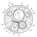
- FIG. 2 is an enlarged perspective view of the tip portion 22, and FIG. 3 is a front view of the tip portion 22 viewed from the longitudinal axis A (see FIG. 1). Further, FIG. 4 is a cross-sectional view of the tip portion 22 along the IV-IV line of FIG. In FIG. 3, the fluid ejection nozzle 40 is shown in a cross-sectional view to show a pipeline.
- the tip portion 22 is made of a hard material such as metal, and is made of a tip portion main body 30 for holding various parts arranged on the tip portion 22 and an insulating resin material. It has a tip surface 30A of the main body 30 and a tip cover 32 that covers the tip outer peripheral surface 30B.
- a lens barrel 38 accommodating an observation window 34 and an optical system 36 constituting the observation unit, and a fluid ejection nozzle (“nozzle”” are shown.
- the tip portion 42A of the air supply / water supply channel 42 connected to (corresponding to) 40 is shown.
- the configuration of the tip surface 28 of the tip portion 22 will be described with reference to FIGS. 2 and 3.
- the tip surface 28 is formed on the surface on the tip side of the tip cover 32.
- the tip surface 28 is formed based on a circular flat surface whose center C is the intersection with the longitudinal axis A.
- the "front side” means the tip side of the insertion portion 12 in the longitudinal axis A direction.
- the tip surface 28 is provided with a forceps opening forming surface portion 56 on which the forceps opening 48 is formed. Further, the illumination windows 44 and 46 are provided on the same surface as the forceps opening forming surface portion 56.
- the tip surface 28 includes a protruding surface portion 58 projecting forward from the forceps opening forming surface portion 56.
- the protruding surface portion 58 has an observation window arrangement surface portion 60 and a nozzle arrangement surface portion 62, an observation window 34 is arranged on the observation window arrangement surface portion 60, and a fluid ejection nozzle 40 is arranged on the nozzle arrangement surface portion 62.
- the observation window arrangement surface portion 60 is provided so as to project forward from the nozzle arrangement surface portion 62.
- the forceps port 48 is communicated with the forceps introduction port 50 of the operation unit 14 via a forceps channel (not shown) inserted inside the insertion unit 12 (see FIG. 1). Therefore, the treatment tool introduced from the forceps introduction port 50 is derived from the forceps opening 48 via the forceps channel described above.
- a suction channel (not shown) is connected to the forceps channel, and the suction operation from the forceps opening 48 is performed via the suction channel by operating the suction button 54 of the operation unit 14 (see FIG. 1).
- the illumination windows 44 and 46 are components of the illumination unit for illuminating the observed portion, and irradiate the observed portion with the illumination light sent from the above-mentioned light source device.
- the circular surfaces 44S and 46S of the illumination windows 44 and 46 are formed by, for example, a flat surface and are arranged perpendicular to the longitudinal axis A.
- the centers of the surfaces 44S and 46S are arranged at positions deviated from the center C of the tip surface 28 to the peripheral edge of the tip surface 28, and face each other with the center B of the surface 34S of the observation window 34 interposed therebetween. Placed in position.
- the observation window 34 is a component of the observation unit for acquiring an image of the observed portion, and the subject light from the observed portion is sent to a solid-state image sensor (not shown) via the optical system 36 shown in FIG. take in.
- the image taken by this observation unit is sent to the above-mentioned processor device as an image signal.
- the circular surface 34S of the observation window 34 is formed of, for example, a flat surface and is arranged perpendicular to the optical axis D of the observation unit.
- the center B of the surface 34S is arranged at a position deviated from the peripheral edge of the tip surface 28 with respect to the center C of the tip surface 28.
- the optical axis D is substantially parallel to the longitudinal axis A, and the center B is located on the optical axis D.
- the fluid ejection nozzle 40 has a base end portion 40A and a tip end portion 40B, and the shape including the base end portion 40A and the tip end portion 40B is formed in an L shape.
- the base end portion 40A constitutes a connection portion connected to the tip end portion 42A of the air supply / water supply channel 42, and is connected to the above-mentioned air supply / water supply device via the air supply / water supply channel 42.
- the conduit 41A of the base end portion 40A has a circular cross section perpendicular to the axis of the conduit 41A, and the circular center E is the tip surface with respect to the center C (see FIG. 3) of the tip surface 28. It is arranged at a position deviated from the peripheral edge of 28, and is arranged at a position closer to the illumination window 44 among the illumination windows 44 and 46 in order to avoid interference with the forceps opening 48.
- the pipe line 41B of the tip portion 40B has a rectangular cross section perpendicular to the axis of the pipe line 41B, and a spout 52 opened toward the observation window 34 is formed at the tip of the pipe line 41B. ..
- the spout 52 is configured as a rectangular opening similar to the cross-sectional shape of the pipeline 41B.
- the air supply / water supply device can be used. Gas is ejected from the ejection port 52 toward the surface 34S of the observation window 34. Then, when the air supply / water supply button 55 is pressed with the finger that closes the leak hole, the cleaning liquid from the air supply / water supply device is ejected from the ejection port 52 toward the surface 34S of the observation window 34.
- a cleaning liquid is sprayed from the ejection port 52 to remove deposits such as blood or body fluid adhering to the surface 34S of the observation window 34, and then gas is discharged from the ejection port 52.
- the cleaning liquid remaining on the surface 34S or the like of the observation window 34 is removed by spraying.
- the positions of the fluid ejection nozzle 40 and the forceps opening 48 are the axes I of the tip portion 40B of the fluid ejection nozzle 40.
- the reference line 66 is on the extension line extending the ejection port 52 in the vertical direction with respect to the reference line 66, at least a part of the forceps opening 48 is provided on the observation window 34 side of the reference line 66.
- the forceps opening 48 is provided close to the fluid ejection nozzle 40.
- the fluid ejection nozzle 40 is arranged on the protruding surface portion 58, and the forceps opening 48 is provided close to the protruding surface portion 58.
- the tip surface 28 is provided with a fluid guiding portion 68 that guides the fluid jetted from the ejection port 52 to the observation window 34 or the like.
- the fluid guiding portion 68 is provided between the fluid ejection nozzle 40 and the observation window 34 on an extension extending the rectangular opening region of the ejection port 52 in the fluid ejection direction.
- FIG. 5 is a plan view showing the configuration of the fluid guiding portion and the fluid route of the fluid guided by the fluid guiding portion.
- the fluid guiding portion 68 is composed of a raised portion 70 that rises from the tip surface 28 toward the tip side in the longitudinal axis A direction.
- the raised portion 70 has a top portion 72 formed on the tip end side of the raised portion 70 in the longitudinal axis A direction. Further, the raised portion 70 has a pair of first guide surfaces 74 and 76. The pair of first guide surfaces 74 and 76 are formed on both sides of the top 72 in the direction of arrow H orthogonal to the straight line G connecting the center F of the opening region of the ejection port 52 and the center B of the observation window 34, respectively. There is. The pair of first guide surfaces 74, 76 guides a part of the fluid jetted from the ejection port 52 to both side portions 34A, 34B of the observation window 34 in the direction of arrow H in the surface 34S of the observation window 34. Functions as a surface. Note that FIG. 3 shows, as an example, a configuration in which the center C is located on the straight line G, but the present invention is not limited to this, and the configuration may be such that the center C is deviated from the straight line G.
- the pair of first guide surfaces 74 and 76 are formed by a slope containing a component oblique to the longitudinal axis A and extending from the straight line G in the direction of arrow H from the fluid ejection nozzle 40 toward the observation window 34. ing.
- the above slope is an example, and may be formed of a surface having another shape as long as the fluid can be guided to both side portions 34A and 34B of the observation window 34.
- the raised portion 70 has a second guide surface 78.
- the second guide surface 78 is provided between the fluid ejection nozzle 40 and the top portion 72, and guides a part of the fluid jetted from the ejection port 52 to the central portion 34C of the observation window 34 via the top portion 72. Functions as a guide surface.
- the second guide surface 78 is formed as a slope inclined toward the tip end side in the longitudinal axis A direction toward the observation window 34 from the fluid ejection nozzle 40.
- the above slope is an example, and may be formed of another surface as long as it has a shape that can guide the fluid to the central portion 34C of the observation window 34.
- first guide surfaces 74 and 76 and the second guide surface 78 are connected to each other via curved ridge lines 80 and 82. Further, the pair of first guide surfaces 74 and 76 and the second guide surface 78 are each composed of surfaces including a streamlined curved surface.
- a fluid guiding portion 68 composed of the raised portion 70 is provided between the fluid ejection nozzle 40 and the observation window 34, and a part of the fluid ejected from the ejection port 52.
- first guide surfaces 74, 76 contains a component that intersects the longitudinal axis A and is formed as an inclined surface that expands in the arrow H direction from the fluid ejection nozzle 40 toward the observation window 34. , The fluid can be smoothly guided toward both side portions 34A and 34B of the observation window 34.
- the fluid jetted from the vicinity of the center F of the ejection port 52 is the central portion of the observation window 34 via the top 72 by the second guide surface 78 as shown by the second fluid route 94 indicated by the arrow L. It is guided to 34C and flows to the central portion 34C. As a result, the central portion 34C of the observation window 34 is cleaned by the fluid flowing along the second fluid route 94.
- the second guide surface 78 of the embodiment is formed as a slope inclined toward the tip end side in the longitudinal axis A direction toward the observation window 34 from the fluid ejection nozzle 40, the fluid is observed in the central portion of the observation window 34. It can be smoothly guided toward 34C.
- the pair of the first guide surfaces 74 and 76 and the second guide surfaces 78 are connected to each other via the curved ridge lines 80 and 82, the fluid flowing along the first fluid routes 90 and 92 can flow.
- the ridges 80 and 82 smoothly flow from the second guide surface 78 toward the pair of first guide surfaces 74 and 76. Thereby, the fluid can be effectively guided toward both side portions 34A and 34B of the observation window 34.
- the pair of first guide surfaces 74 and 76 includes a streamlined curved surface
- the fluid is smoothly guided from the pair of first guide surfaces 74 and 76 toward both side portions 34A and 34B of the observation window 34. be able to.
- the second guide surface 78 also includes a streamlined curved surface
- the fluid can be smoothly guided from the second guide surface 78 toward the central portion 34C of the observation window 34.
- the first guide surface 74, 76 and the second guide surface 78 so as to include such a streamlined surface, the fluid vigorously collides with the pair of first guide surfaces 74, 76 and the second guide surface 78. Even in this case, it is possible to suppress the scattering of the fluid, so that most of the fluid injected from the ejection port 52 can be effectively used for cleaning the observation window 34.
- the above streamlined surface refers to, for example, a curved surface that smoothly bulges from the tip surface 28 toward the tip side of the longitudinal axis A.
- the first guide surface 74, 76 and the second guide surface 78 are flat with the streamlined surface if the fluid can be smoothly guided to the observation window 34, in addition to the embodiment composed of only the streamlined surface. It may be a surface formed by connecting the shaped surfaces.
- the fluid guiding unit 68 of the present embodiment further includes the following configuration as a preferred embodiment.
- the fluid guiding unit 68 is provided with a flat third guide surface 84 in order to allow the fluid that has passed through the second guide surface 78 to flow smoothly toward the observation window 34.
- the third guide surface 84 By providing the third guide surface 84, the fluid directed from the second guide surface 78 toward the central portion 34C of the observation window 34 via the top 72 is smoothly guided to the central portion 34C of the observation window 34 by the third guide surface 84. can do.
- the fluid guiding unit 68 guides the fluid ejected from the ejection port 52, which is separated from the pair of first guide surfaces 74 and 76, to the side portions 34A and 34B of the observation window 34. It has guide surfaces 86 and 88.
- the fourth guide surfaces 86 and 88 By providing the fourth guide surfaces 86 and 88 in the fluid guide portion 68, the fluids ejected from the ejection port 52 and deviating from the pair of first guide surfaces 74 and 76 in the arrow H direction are the fluids deviated from the pair of first guide surfaces 74 and 76 by the arrows M and N.
- the fourth guide surfaces 86 and 88 guide the observation window 34 to both side portions 34A and 34B and flow to both side portions 34A and 34B.
- both side portions 34A and 34B can be washed together with the fluid flowing along the first fluid routes 90 and 92 indicated by arrows J and K, so that the cleanability of both side portions 34A and 34B is further improved.
- the surface characteristics of the tip surface 28 will be described.
- the tip is used.
- the surface 28 is imparted with water repellency and hydrophilicity.
- FIG. 6 is a diagram illustrating a water-repellent and hydrophilic region of the tip surface 28.
- the nozzle facing region 102 between the fluid ejection nozzle 40 and the observation window 34 is a water-repellent region.
- the region 104 adjacent to the forceps opening on the side opposite to the nozzle facing region 102 across the forceps opening 48 is set as a hydrophilic region.
- the tip surface 28 has a nozzle peripheral region 106 on the side opposite to the forceps opening 48 with the nozzle facing region 102 sandwiched therein as a water-repellent region.
- the tip surface 28 has a fluid discharge region 108 on the opposite side of the nozzle facing region 102 with the observation window 34 as a hydrophilic region.
- the surface roughness Ra of the tip surface 28 can be made smaller than 0.4. Preferably, it can be done by making the surface roughness Ra smaller than 0.2. Further, in order to make the region hydrophilic, for example, the surface roughness Ra can be made larger than 0.4.
- the contact angle of the tip surface 28 is preferably 80 ° or more in the water-repellent region. Further, it is preferable that the contact angle of the hydrophilic region is 70 ° or less.
- a value measured using a "wetting property evaluation device LSE-ME1 (contact angle meter)" manufactured by Daiko Seisakusho Co., Ltd. can be used.
- a water-repellent region it can be formed by applying a water-repellent coating in addition to the above-mentioned method of forming by surface roughness.
- a coating agent such as a fluorine-based resin or a silicon-based resin can be used, and a water-repellent region can be obtained by applying and curing these coating agents.
- FIG. 7 is a diagram illustrating the flow of liquid on the front end surface of the endoscope of the comparative example.
- FIG. 8 is a diagram illustrating a flow of liquid on the front end surface of the endoscope of the present embodiment.
- the tip surface 128 of the endoscope of the comparative example is a tip surface having no water-repellent and hydrophilic region on the tip surface.
- the liquid 110 remaining in the forceps opening 48 is drawn out by surface tension at the end portion of the forceps opening 48 and the side surface of the protruding surface portion 58. Further, the liquid 110 is drawn out by the unevenness of the fluid ejection nozzle 40 and the fluid guiding portion 68 provided on the tip surface 128. In this state, when the gas is injected from the fluid ejection nozzle 40, the liquid 110 drawn out between the observation window 34 and the fluid ejection nozzle 40 is sent to the observation window 34.
- the liquid 110 remaining in the forceps port 48 continues to be drawn out by the gas ejected from the fluid ejection nozzle 40, the gas ejected from the fluid ejection nozzle 40 and the liquid 110 are mixed on the observation window 34. Keep moving. Therefore, it is likely that the liquid is reflected in the observation image and the liquid remaining in the observation window 34 cannot be removed in many cases.
- the tip surface 28 of the present embodiment by making the nozzle facing region 102 water repellent, the liquid 110 that cannot be completely sucked and remains in the forceps opening 48 is observed as the fluid ejection nozzle 40. It is possible to prevent the flow into the area between the window 34 and the window 34. Further, by making the forceps opening adjacent region 104 hydrophilic, the liquid 110 remaining in the forceps opening 48 can be guided to the forceps opening adjacent region 104. By preventing liquids such as residual water and body fluids derived from the liquid 110 from remaining in the nozzle facing region 102, the liquid 110 remaining in the forceps port 48 continues to be drawn out by the gas ejected from the fluid ejection nozzle 40. , It is possible to prevent the liquid from moving to the observation window 34 side.
- the observation window 34 and the fluid ejection nozzle 40 are arranged on the protruding surface portion 58.
- the liquid 110 remaining in the forceps opening 48 tends to be in a state of being connected by the forceps opening 48 and the protruding surface portion 58 due to surface tension.
- the nozzle facing region 102 water repellent, it is possible to prevent the liquid 110 from flowing between the observation window 34 and the fluid ejection nozzle 40, so that the fluid ejection nozzle 40 can be prevented from flowing. It is possible to prevent the liquid 110 from moving to the observation window 34 due to the gas ejected from.
- the protruding surface portion 58 is provided with a nozzle arranging surface portion 62 and an observation window arranging surface portion 60 projecting forward from the nozzle arranging surface portion 62. Further, a fluid guiding portion 68 is provided between the observation window 34 and the fluid ejection nozzle 40. Therefore, the liquid 110 remaining in the forceps opening 48 is likely to be drawn out between them. According to the present embodiment, by making the nozzle facing region 102 water repellent, it is possible to prevent the liquid from flowing between the observation window 34 and the fluid ejection nozzle 40, so that the fluid ejection nozzle 40 can be used. It is possible to prevent the liquid from moving to the observation window 34 due to the injected gas.
- the positional relationship on the front side of the observation window arrangement surface portion 60 and the nozzle arrangement surface portion 62 is not limited to these.
- the observation window arrangement surface portion 60 and the nozzle arrangement surface portion 62 may be provided on the same surface in the protruding surface portion 58.
- the observation window 34 and the fluid ejection nozzle 40 may be arranged on the same surface as the forceps opening forming surface portion 56, or either one may be arranged on the same surface as the forceps opening forming surface portion 56. Even with these configurations, by making the nozzle facing region 102 water repellent and the forceps port adjacent region 104 hydrophilic, the region between the observation window 34 and the fluid ejection nozzle 40 (nozzle facing region 102) can be formed. Since it is possible to prevent the liquid 110 from flowing, it is possible to prevent the liquid 110 remaining in the forceps port 48 from moving to the observation window 34 due to the gas ejected from the fluid ejection nozzle 40.
- the position of the forceps opening 48 is located from the reference line 66 extending the ejection port 52 as shown in FIG. Even if the liquid 110 is arranged on the observation window 34 side, it is possible to prevent the liquid 110 from moving to the observation window 34. As a result, the position of the forceps opening 48 can be arranged on the tip surface 28 without limitation, so that the diameter of the insertion portion can be reduced.
- a fluid guiding portion 68 is provided on the tip surface of the endoscope 10 of the present embodiment, and the fluid jetted from the fluid ejection nozzle 40 is effectively flowed to both ends of the observation window 34.
- the forceps opening 48 is arranged adjacent to the fluid ejection nozzle 40, the gas ejected from the fluid ejection nozzle 40 is the forceps opening 48. It will be sprayed to the vicinity. Therefore, when the liquid sucked by the forceps opening 48 remains in the forceps opening 48, the liquid is drawn out by the gas ejected from the fluid ejection nozzle 40, and the liquid easily flows into the observation window 34.
- the liquid remaining in the forceps opening 48 is placed in the region opposite the forceps opening 48 with respect to the path of the gas ejected from the fluid ejection nozzle 40.
- Can guide liquids This makes it possible to prevent the liquid 110 remaining in the forceps opening 48 from moving to the observation window 34 due to the gas ejected from the fluid ejection nozzle 40.
- the liquid 110 remaining in the forceps opening 48 exceeds the water-repellent nozzle facing region 102 and is in the vicinity of the fluid ejection nozzle 40 on the opposite side of the forceps opening 48. It can be prevented from moving to. Further, it is possible to prevent the liquid remaining on the tip surface 28 from staying in the vicinity of the fluid ejection nozzle 40. Therefore, it is possible to prevent the liquid from staying even in the vicinity of the fluid ejection nozzle 40 on the opposite side of the forceps opening 48, and the gas ejected from the fluid ejection nozzle 40 moves the liquid to the observation window 34. Can be prevented.
- the fluid discharge region 108 hydrophilic, the liquid on the observation window 34 can be easily discharged from the fluid discharge region 108. As a result, the gas ejected from the fluid ejection nozzle 40 can easily discharge the liquid on the observation window 34.
- the entire protruding surface portion 58 may be water repellent. Since the fluid ejection nozzle 40 and the observation window 34 are arranged on the protruding surface portion 58, the protruding surface portion 58 is made water repellent to prevent the liquid 110 remaining in the forceps opening 48 from being connected to the protruding surface portion 58. Can be done. As a result, it is possible to prevent the liquid 110 from being drawn out onto the protruding surface portion 58 by the gas ejected from the fluid ejection nozzle 40, and it is possible to prevent the liquid 110 from moving to the observation window 34.
Abstract
観察窓の液切れ性の向上を図ることができる内視鏡を提供する。被検体内に挿入される先端側に先端面(28)を有する挿入部(12)と、先端面(28)に設けられ、被検体内を観察するための観察窓(34)と、先端面(28)に設けられ、観察窓(34)に向けて流体を噴出する流体噴出用ノズル(40)と、先端面に設けられ、処置具を導出又は流体を吸引するための鉗子口(48)と、を備える。先端面(28)は、流体噴出用ノズル(40)と観察窓(34)との間のノズル対向領域(102)に撥水性を有し、かつ鉗子口(48)を挟んでノズル対向領域(102)とは反対側の鉗子口隣接領域(104)に親水性を有する。
Description
本発明は内視鏡に係り、特に挿入部の先端面に配置された観察窓の液切れ性の向上を図る内視鏡に関する。
内視鏡の挿入部の先端面には、被観察部位からの被写体光を取り込む観察窓、及び被観察部位に照明光を照射する照明窓が配置される。また、先端面には、観察窓に付着した体液等の付着物を除去するために観察窓に向けて洗浄液(例えば水)と気体(例えば空気)を噴射する流体噴射用ノズルが配置される。
観察窓の洗浄時には、まず、流体噴射用ノズルの噴射口から洗浄液を噴射することにより観察窓に付着した付着物を除去し、続いて、噴射口から気体を噴射することにより観察窓に残留する洗浄液を除去する。
特許文献1には、観察窓の洗浄において、噴出口から噴射された流体を観察窓と観察窓に隣接領域とに流すことを可能とした内視鏡が開示されている。この内視鏡によれば、流体噴出用ノズルと観察窓との間に、流体誘導部と、流体誘導部で誘導された流体の一部を観察窓に導く第1の流体ルートと、流体誘導部を外れた流体を上記の隣接領域に導く第2の流体ルートとを備えている。
特許文献2には、送気送液用のノズルからの送気によって観察窓に残留する残液を除去することを可能とした内視鏡が開示されている。この内視鏡によれば、先端カバーの平坦部の少なくとも一部、観察窓の窓面、及び傾斜部の少なくとも一部を、液体に対する親和性が高い表面特性を有する先端カバーとしている。
内視鏡の先端面には、処置具を導出する、あるいは、流体を吸引するための鉗子口が設けられている。この鉗子口の開口内付近は、観察窓の洗浄水、又は、観察対象部位の洗浄水等の液体が吸引しきれずに残存する場合がある。鉗子口の開口付近に液体が残存した状態で、流体噴出用ノズルの噴出口から気体を噴射した場合、鉗子口の開口付近に液体が残る限り、噴射した気体により観察窓の方向に移動し続け、それが観察像に映り込んだり、また観察窓に液体(水滴)が残ってしまうという問題が生じていた。
本発明は、このような事情に鑑みてなされたものであり、観察窓の液切れ性を向上することができる内視鏡を提供することを目的とする。
本発明の目的を達成するために、本発明に係る内視鏡は、被検体内に挿入される先端側に先端面を有する挿入部と、先端面に設けられ、被検体内を観察するための観察窓と、先端面に設けられ、観察窓に向けて流体を噴出するノズルと、先端面に設けられ、処置具を導出又は流体を吸引するための鉗子口と、を備え、先端面は、ノズルと観察窓との間のノズル対向領域に撥水性を有し、かつ鉗子口を挟んでノズル対向領域とは反対側の鉗子口隣接領域に親水性を有する。
本発明の一形態は、先端面は、鉗子口が形成された鉗子口形成面部と、鉗子口形成面部から先端側となる前方に向かって突出して形成された突出面部と、を有し、突出面部に観察窓及びノズルの少なくとも一方が配置されていることが好ましい。
本発明の一形態は、突出面部は、観察窓が配置された観察窓配置面部と、ノズルが配置されたノズル配置面部と、を有し、観察窓配置面部は、ノズル配置面部よりも前方に突出していることが好ましい。
本発明の一形態は、突出面部は撥水性を有することが好ましい。
本発明の一形態は、鉗子口は、ノズル対向領域に近接した位置に配置されることが好ましい。
本発明の一形態は、先端面は、ノズル対向領域を挟んで鉗子口とは反対側のノズル周辺領域に撥水性を有することが好ましい。
本発明の一形態は、ノズルは、流体を噴出する噴出口を有し、鉗子口の少なくとも一部が、噴出口の延長線上となる基準線よりも観察窓側に設けられることが好ましい。
本発明の一形態は、先端面は、観察窓を挟んでノズル対向領域とは反対側の流体排出領域に親水性を有することが好ましい。
本発明によれば、内視鏡の観察窓の液切れ性を向上させることができる。
以下、添付図面に従って本発明に係る内視鏡の好ましい実施形態について説明する。
図1は、本発明の実施形態に係る内視鏡10の全体図である。
図1に示すように、内視鏡10は、被検体内に挿入される挿入部12と、挿入部12の基端に設けられた操作部14と、内視鏡10を不図示の光源装置、プロセッサ装置及び送気送水装置等のシステム構成機器に接続するユニバーサルケーブル16と、を備えている。
挿入部12は、先端と基端と挿入部12の軸である長手軸Aとを有し、基端から先端に向って順に軟性部18、湾曲部20及び先端部22を備えている。
軟性部18は、可撓性を有し、挿入部12の挿入経路に沿って任意の方向に湾曲可能である。湾曲部20は、操作部14に回動自在に設けられたアングルノブ24、26を操作することにより上下方向と左右方向のそれぞれに湾曲され、先端部22が向く方向を任意の方向に変更可能である。また、先端部22は、挿入部12の先端に設けられた先端面28(図2参照)を有している。
図2は、先端部22を拡大して示した斜視図であり、図3は、先端部22を長手軸A(図1参照)方向から正面視した正面図である。また、図4は、図2のIV-IV線に沿う先端部22の断面図である。なお、図3において、流体噴出用ノズル40は管路を示すため断面図で記載している。
図4に示すように、先端部22は、金属等の硬質材料により構成され、先端部22に配置される各種部品を保持する先端部本体30と、絶縁性の樹脂材料により構成され、先端部本体30の先端面30Aと先端外周面30Bを被覆する先端カバー32と、を有している。なお、図4には、先端部本体30及び先端カバー32に保持される部品として、観察部を構成する観察窓34及び光学系36を収容した鏡胴38と、流体噴出用ノズル(「ノズル」に相当する)40に接続される送気送水チャンネル42の先端部分42Aとが示されている。
図2及び図3を用いて、先端部22の先端面28の構成を説明する。先端面28は先端カバー32の先端側の面に形成される。先端面28は、長手軸Aとの交差位置を先端面28の中心Cとする円形状の平坦面を基調にして形成される。なお、以下の説明において、「前方側」とは、挿入部12の長手軸A方向の先端側を言う。
先端面28には、鉗子口48が形成される鉗子口形成面部56を備える。また、鉗子口形成面部56と同一面上に、照明窓44、46が設けられている。先端面28は、鉗子口形成面部56から前方側に突出した突出面部58を備える。突出面部58は、観察窓配置面部60及びノズル配置面部62を有し、観察窓配置面部60に観察窓34が配置され、ノズル配置面部62に流体噴出用ノズル40が配置される。観察窓配置面部60は、ノズル配置面部62より前方側に突出して設けられている。
鉗子口48は、挿入部12(図1参照)の内部に挿通された不図示の鉗子チャンネルを介して操作部14の鉗子導入口50に連通される。したがって、鉗子導入口50から導入された処置具は、上記の鉗子チャンネルを介して鉗子口48から導出される。
また、上記の鉗子チャンネルには不図示の吸引チャンネルが連結されており、操作部14(図1参照)の吸引ボタン54の操作により鉗子口48からの吸引動作が吸引チャンネルを介して行われる。
照明窓44、46は、被観察部位を照明するための照明部の構成要素であり、上記の光源装置から送られてきた照明光を被観察部位に照射する。
照明窓44、46の円形の表面44S、46Sは、例えば、平坦面により形成され、長手軸Aと垂直に配置される。そして、表面44S、46Sの各々の中心は、先端面28の中心Cに対して先端面28の周縁に偏倚した位置に配置され、且つ観察窓34の表面34Sの中心Bを挟んで互いに対向した位置に配置される。
観察窓34は、被観察部位の画像を取得するための観察部の構成要素であり、被観察部位からの被写体光を、図4に示した光学系36を介して不図示の固体撮像素子に取り込む。この観察部によって撮影された画像は、画像信号として上記のプロセッサ装置に送られる。
観察窓34の円形の表面34Sは、例えば、平坦面により形成され、観察部の光軸Dと垂直に配置される。そして、表面34Sの中心Bは、先端面28の中心Cに対して先端面28の周縁に偏倚した位置に配置される。なお、光軸Dは長手軸Aと略平行であり、光軸D上に中心Bが位置している。
流体噴出用ノズル40は、図4に示すように、基端部分40Aと先端部分40Bとを有し、基端部分40Aと先端部分40Bとを含む形状がL字状に構成されている。
基端部分40Aは、送気送水チャンネル42の先端部分42Aに接続される接続部分を構成し、送気送水チャンネル42を介して上記の送気送水装置に接続される。また、基端部分40Aの管路41Aは、管路41Aの軸線に垂直な断面が円形に形成され、その円形の中心Eは、先端面28の中心C(図3参照)に対して先端面28の周縁に偏倚した位置に配置され、且つ鉗子口48との干渉を避けるため照明窓44、46のうちの照明窓44に近い位置に配置される。
先端部分40Bの管路41Bは、管路41Bの軸線に垂直な断面が長方形に形成され、その管路41Bの先端には、観察窓34に向けて開口された噴出口52が形成されている。この噴出口52は、管路41Bの断面形状と同様に長方形の開口として構成されている。
このように構成された流体噴出用ノズル40によれば、操作部14(図1参照)の送気送水ボタン55に形成されたリーク孔(不図示)を指で閉鎖すると、送気送水装置からの気体が噴出口52から観察窓34の表面34Sに向けて噴射される。そして、上記のリーク孔を閉鎖した指で送気送水ボタン55を押下すると、送気送水装置からの洗浄液が噴出口52から観察窓34の表面34Sに向けて噴射される。なお、観察窓34の洗浄の手順としては、例えば、噴出口52から洗浄液を噴射して観察窓34の表面34Sに付着した血液又は体液等の付着物を除去した後、噴出口52から気体を噴射して観察窓34の表面34S等に残留した洗浄液を除去する。
また、図3に示すように、先端面28を内視鏡10の先端側から見た場合、流体噴出用ノズル40と鉗子口48の位置は、流体噴出用ノズル40の先端部分40Bの軸線Iに対して垂直方向に噴出口52を延長した延長線上を基準線66としたとき、鉗子口48の少なくとも一部が、基準線66よりも観察窓34側に設けられている。鉗子口48は、流体噴出用ノズル40に近接して設けられている。本実施形態においては、流体噴出用ノズル40は突出面部58に配置されており、鉗子口48は、突出面部58に近接して設けられている。
(流体誘導部の構成)
次に、噴出口52から噴射された流体の流路に関する構成について詳説する。
次に、噴出口52から噴射された流体の流路に関する構成について詳説する。
図2から図4に示すように、先端面28には、噴出口52から噴射された流体を観察窓34等へ誘導する流体誘導部68が備えられている。この流体誘導部68は、流体噴出用ノズル40と観察窓34との間であって、噴出口52の長方形の開口領域を流体噴出方向に延長した延長上に設けられている。
図5は、流体誘導部の構成及び流体誘導部によって誘導される流体の流体ルートを示した平面図である。流体誘導部68は、先端面28から長手軸A方向の先端側に隆起した隆起部70により構成されている。
図3及び図5に示すように、隆起部70は、隆起部70のうち長手軸A方向の先端側に形成された頂部72を有する。また、隆起部70は、一対の第1ガイド面74、76を有している。一対の第1ガイド面74、76は、噴出口52の開口領域の中心Fと観察窓34の中心Bとを結ぶ直線Gに対し、直交する矢印H方向における頂部72の両側にそれぞれ形成されている。この一対の第1ガイド面74、76は、噴出口52から噴射された流体の一部を、観察窓34の表面34Sのうち矢印H方向における観察窓34の両側部34A、34Bへ誘導するガイド面として機能する。なお、図3では、一例として、直線G上に中心Cが位置する構成が示されているが、これに限らず、直線Gに対して中心Cがずれている構成であってもよい。
一対の第1ガイド面74、76は、一例として、長手軸Aに対して斜交する成分を含み流体噴出用ノズル40から観察窓34に向かうに従って直線Gから矢印H方向に拡がる斜面で形成されている。なお、上記の斜面は一例であり、流体を観察窓34の両側部34A、34Bへ誘導可能な形状であれば、他の形状の面で構成されていてもよい。
また、隆起部70は、第2ガイド面78を有している。この第2ガイド面78は、流体噴出用ノズル40と頂部72との間に設けられ、噴出口52から噴射された流体の一部を、頂部72を介して観察窓34の中央部34Cへ誘導するガイド面として機能する。
第2ガイド面78は、一例として、流体噴出用ノズル40から観察窓34に向かうに従って長手軸A方向の先端側に傾斜した斜面で形成されている。なお、上記の斜面は一例であり、流体を観察窓34の中央部34Cへ誘導可能な形状であれば、他の面で構成されていてもよい。
また、一対の第1ガイド面74、76と第2ガイド面78とは、曲線状の稜線部80、82を介して互いに連接されている。また、一対の第1ガイド面74、76と第2ガイド面78は、それぞれ流線型の曲面を含む面によって構成されている。
次に、第1ガイド面74、76と第2ガイド面78とを備えた流体誘導部68の作用について説明する。
図5に示すように、流体噴出用ノズル40の噴出口52から噴射された流体の一部、具体的には、噴出口52の中心Fから矢印H方向に離れた位置から噴射された流体は、矢印J、Kで示す第1流体ルート90、92で示すように、第2ガイド面78から稜線部80、82を経由して一対の第1ガイド面74、76に流れる。そして、一対の第1ガイド面74、76により観察窓34の両側部34A、34Bへ誘導され、両側部34A、34Bに流れる。これにより、観察窓34の両側部34A、34Bが、第1流体ルート90、92に沿って流れる流体によって洗浄される。
このように挿入部12の先端面28において、隆起部70により構成された流体誘導部68を流体噴出用ノズル40と観察窓34との間に設け、噴出口52から噴射された流体の一部を、頂部72の両側にそれぞれ形成された一対の第1ガイド面74、76により観察窓34の両側部34A、34Bへ誘導するように構成したので、観察窓34の両側部34A、34Bの洗浄性を向上させることができる。
また、一対の第1ガイド面74、76は、長手軸Aに対して斜交する成分を含み流体噴出用ノズル40から観察窓34に向かうに従って、矢印H方向に拡がる斜面で形成されているので、流体を観察窓34の両側部34A、34Bへ向けて円滑に誘導することができる。
一方、噴出口52の中心Fとのその近傍から噴射される流体は、矢印Lで示す第2流体ルート94で示すように、第2ガイド面78により頂部72を介して観察窓34の中央部34Cへ誘導されて中央部34Cに流れる。これにより、観察窓34の中央部34Cが、第2流体ルート94に沿って流れる流体によって洗浄される。
また、実施形態の第2ガイド面78は、流体噴出用ノズル40から観察窓34に向かうに従って長手軸A方向の先端側に傾斜した斜面で形成されているので、流体を観察窓34の中央部34Cへ向けて円滑に誘導することができる。
また、一対の第1ガイド面74、76と第2ガイド面78は、曲線状の稜線部80、82を介して互いに連接されているので、第1流体ルート90、92に沿って流れる流体は、稜線部80、82により第2ガイド面78から一対の第1ガイド面74、76に向けて滑らかに流れる。これにより、流体を観察窓34の両側部34A、34Bへ向けて効果的に誘導することができる。
さらに、一対の第1ガイド面74、76は、流線型の曲面を含んでいるので、一対の第1ガイド面74、76から観察窓34の両側部34A、34Bへ向けて流体を滑らかに誘導することができる。また、第2ガイド面78も同様に流線型の曲面を含んでいるので、第2ガイド面78から観察窓34の中央部34Cへ向けて流体を滑らかに誘導することができる。このような流線型の面を含むように第1ガイド面74、76と第2ガイド面78を構成することにより、一対の第1ガイド面74、76と第2ガイド面78に流体が勢いよく衝突した場合でも、その流体が飛散することを抑制することができるので、噴出口52から噴射された大部分の流体を観察窓34の洗浄に有効利用することができる。
上記の流線型の面とは、例えば、先端面28から長手軸Aの先端側に向けて滑らかに膨らんだ曲面を指す。また、第1ガイド面74、76及び第2ガイド面78は、上記の流線型の面だけで構成された態様の他、流体を観察窓34に円滑に誘導可能であれば、流線型の面と平坦状の面とが連接されて構成された面であってもよい。
本実施形態の流体誘導部68は、好ましい態様として、以下の構成をさらに備えている。
流体誘導部68は、第2ガイド面78を通過した流体を観察窓34に向けて円滑に流すために、平坦な第3ガイド面84を備えている。第3ガイド面84を備えることにより、第2ガイド面78から頂部72を介して観察窓34の中央部34Cへ向かう流体を、第3ガイド面84によって観察窓34の中央部34Cへ円滑に誘導することができる。
また、流体誘導部68は、噴出口52から噴射された流体のうち一対の第1ガイド面74、76から外れた流体を、観察窓34の両側部34A、34Bへ誘導するために、第4ガイド面86、88を備えている。
流体誘導部68に第4ガイド面86、88を備えることにより、噴出口52から噴射された流体のうち一対の第1ガイド面74、76から矢印H方向に外れた流体は、矢印M、Nで示す第3流体ルート96、98で示すように、第4ガイド面86、88により観察窓34の両側部34A、34Bへ誘導され、両側部34A、34Bに流れる。これにより、矢印J、Kで示す第1流体ルート90、92に沿って流れる流体と一緒に両側部34A、34Bを洗浄することができるので、両側部34A、34Bの洗浄性がさらに向上する。
(先端面の表面特性)
次に、先端面28の表面特性について説明する。本実施形態においては、先端面28に残った液体及び鉗子口48で吸引しきれず残った液体が、流体噴出用ノズルから噴射される気体により、観察窓34に移動することを防止するため、先端面28に撥水性及び親水性が付与されている。
次に、先端面28の表面特性について説明する。本実施形態においては、先端面28に残った液体及び鉗子口48で吸引しきれず残った液体が、流体噴出用ノズルから噴射される気体により、観察窓34に移動することを防止するため、先端面28に撥水性及び親水性が付与されている。
図6は、先端面28の撥水性と親水性の領域を説明する図である。図6に示すように、本実施形態の先端面28によれば、流体噴出用ノズル40と観察窓34との間のノズル対向領域102を撥水性の領域とする。また、鉗子口48を挟んでノズル対向領域102とは反対側の鉗子口隣接領域104を親水性の領域とする。
また、先端面28は、ノズル対向領域102を挟んで鉗子口48とは反対側のノズル周辺領域106を撥水性の領域とする。
また、先端面28は、観察窓34を挟んでノズル対向領域102とは反対側の流体排出領域108を親水性の領域とする。
撥水性の領域とするためには、例えば、先端面28の表面粗さRaを0.4より小さくすることにより行うことができる。好ましくは、表面粗さRaを0.2より小さくすることにより行うことができる。また、親水性の領域とするためには、例えば、表面粗さRaを0.4より大きくすることにより行うことができる。表面粗さにより、撥水性及び親水性の領域を形成するためには、金型の研磨工程により全体が親水性の領域(例えば、Ra=0.4)となるように切削した後、切削した表面のうち、撥水性としたい領域(ノズル対向領域102、ノズル周辺領域106)を研磨(例えば、Ra=0.2となりように研磨)することで、効率よく形成することができる。
また、先端面28の接触角は、撥水性の領域の接触角を80°以上とすることが好ましい。また、親水性の領域の接触角を70°以下とすることが好ましい。なお、接触角は、株式会社大興製作所「ぬれ性評価装置 LSE-ME1 (接触角計)」を用いて測定した値を用いることができる。
撥水性の領域を形成するためには、上記の表面粗さにより形成する方法の他に、撥水コーティングを行うことにより形成することができる。撥水コーティングとしては、フッ素系樹脂、又は、シリコン系樹脂等のコーティング剤を用いることができ、これらのコーティング剤を塗布して硬化させることにより、撥水領域とすることができる。
次に、先端面28に撥水性の領域と親水性の領域を設けることの効果について説明する。図7は、比較例の内視鏡の先端面の液体の流れを説明する図である。図8は、本実施形態の内視鏡の先端面の液体の流れを説明する図である。
比較例の内視鏡の先端面128は、先端面に撥水性及び親水性の領域を有さない先端面である。この場合、図7に示すように、鉗子口48に残存した液体110が、鉗子口48の端部と突出面部58との側面とで表面張力により、引き出される。さらに、先端面128に設けられた流体噴出用ノズル40と流体誘導部68等の凹凸により、液体110が引き出される。この状態で、流体噴出用ノズル40から気体が噴射されると、観察窓34と流体噴出用ノズル40の間に引き出された液体110が観察窓34に送液される。さらに、流体噴出用ノズル40から噴出される気体により、鉗子口48に残存する液体110が引き出され続けるため、流体噴出用ノズル40から噴出される気体と液体110が混ざった状態で観察窓34上を移動し続ける。そのため、液体が観察像に映り込んだり、また観察窓34に残留する液体を除去できない場合が多く発生しやすい。
本実施形態の先端面28によれば、図8に示すように、ノズル対向領域102を撥水性とすることで、吸引しきれず、鉗子口48に残る液体110が、流体噴出用ノズル40と観察窓34との間の領域に流れることを防止することができる。また、鉗子口隣接領域104を親水性とすることで、鉗子口48に残る液体110を鉗子口隣接領域104に誘導することができる。ノズル対向領域102に液体110由来の残水及び体液などの液体が残存することを防止することで、流体噴出用ノズル40から噴射された気体により、鉗子口48に残存する液体110が引き出され続け、観察窓34側に液体が移動することを防止することができる。
また、観察窓34及び流体噴出用ノズル40は、突出面部58に配置されている。鉗子口48と突出面部58が近接して配置されると、表面張力により、鉗子口48に残存する液体110が、鉗子口48と突出面部58とで繋がった状態になりやすい。本実施形態によれば、ノズル対向領域102を撥水性とすることで、観察窓34と流体噴出用ノズル40との間に液体110が流れることを防止することができるので、流体噴出用ノズル40から噴射される気体により液体110が観察窓34に移動することを防止することができる。
また、突出面部58は、ノズル配置面部62とノズル配置面部62より前方に突出した観察窓配置面部60が設けられている。また、観察窓34及び流体噴出用ノズル40の間には、流体誘導部68が設けられている。したがって、それらの間に鉗子口48に残存する液体110が引き出されやすい。本実施形態によれば、ノズル対向領域102を撥水性とすることで、観察窓34と流体噴出用ノズル40との間に液体が流れることを防止することができるので、流体噴出用ノズル40から噴射される気体により液体が観察窓34に移動することを防止することができる。
なお、観察窓配置面部60及びノズル配置面部62の前方側の位置関係は、これらに限定されない。観察窓配置面部60及びノズル配置面部62を突出面部58において同一面上に設けてもよい。また、鉗子口形成面部56と同一面上に観察窓34及び流体噴出用ノズル40を配置してもよく、いずれか一方を鉗子口形成面部56と同一面上に配置してもよい。これらの構成であっても、ノズル対向領域102を撥水性、鉗子口隣接領域104を親水性とすることで、観察窓34と流体噴出用ノズル40との間の領域(ノズル対向領域102)に液体110が流れることを防止することができるので、流体噴出用ノズル40から噴射される気体により鉗子口48に残存する液体110が観察窓34に移動することを防止することができる。
また、ノズル対向領域102に鉗子口48に残存する液体110が流れることを防止することができるので、鉗子口48の位置は、図3に示すように、噴出口52を延長した基準線66よりも観察窓34側に配置しても、液体110が観察窓34に移動することを防止することができる。これにより、先端面28において鉗子口48の位置を制限することなく配置できるので、挿入部の小径化を図ることができる。
また、本実施形態の内視鏡10の先端面には流体誘導部68を備え、流体噴出用ノズル40から噴射された流体を、観察窓34の両端部に効果的に流している。その際、図2及び図3に記載されているように、鉗子口48が、流体噴出用ノズル40に隣接して配置されていると、流体噴出用ノズル40から噴射された気体が鉗子口48付近まで、噴射されることになる。そのため、鉗子口48が吸引した液体が、鉗子口48に残った状態であると、流体噴出用ノズル40から噴射された気体により、液体が引き出され、観察窓34に液体が流れやすくなる。鉗子口隣接領域104を親水性とすることにより、鉗子口48に残存する液体を、流体噴出用ノズル40から噴射される気体の経路に対して、鉗子口48を挟んで反対側の領域に、液体を導くことができる。これにより、鉗子口48に残存した液体110が流体噴出用ノズル40から噴射された気体により観察窓34に移動することを防止することができる。
また、ノズル周辺領域106を撥水性とすることで、鉗子口48に残存した液体110が、撥水性であるノズル対向領域102を超えて、鉗子口48の反対側の流体噴出用ノズル40の近傍に移動することを防止することができる。さらに、先端面28に残る液体が、流体噴出用ノズル40の近傍に留まることを防止することができる。したがって、鉗子口48の反対側の流体噴出用ノズル40付近においても、液体が留まることを防止することができ、流体噴出用ノズル40から噴射される気体により、液体が観察窓34に移動することを防止することができる。
また、流体排出領域108を親水性とすることで、観察窓34上にある液体を、流体排出領域108から排出しやすくすることができる。これにより、流体噴出用ノズル40から噴射される気体により、観察窓34上の液体を排出しやすくすることができる。
なお、図6においては、ノズル対向領域102を撥水性としているが、突出面部58全体を撥水性としてもよい。流体噴出用ノズル40と観察窓34が突出面部58に配置されているため、突出面部58を撥水性とすることで、鉗子口48に残存する液体110が突出面部58と繋がることを防止することができる。これにより、流体噴出用ノズル40から噴射される気体により液体110が突出面部58上に引き出されることを防止することができ、観察窓34に移動することを防止することができる。
10 内視鏡
12 挿入部
14 操作部
16 ユニバーサルケーブル
18 軟性部
20 湾曲部
22 先端部
24、26 アングルノブ
28、128 先端面
30 先端部本体
30A 先端部本体の先端面
30B 先端部本体の先端外周面
32 先端カバー
34 観察窓
34A 両側部
34B 両側部
34C 中央部
34S 観察窓の表面
36 光学系
38 鏡胴
40 流体噴出用ノズル
40A 基端部分
40B 先端部分
41A 基端部分の管路
41B 先端部分の管路
42 送気送水チャンネル
42A 送気送水チャンネルの先端部分
44、46 照明窓
44S、46S 照明窓の表面
48 鉗子口
50 鉗子導入口
52 噴出口
54 吸引ボタン
55 送気送水ボタン
56 鉗子口形成面部
58 突出面部
60 観察窓配置面部
62 ノズル配置面部
66 基準線
68 流体誘導部
70 隆起部
72 頂部
74、76 第1ガイド面
78 第2ガイド面
80、82 稜線部
84 第3ガイド面
86、88 第4ガイド面
90、92 第1流体ルート
94 第2流体ルート
96、98 第3流体ルート
102 ノズル対向領域
104 鉗子口隣接領域
106 ノズル周辺領域
108 流体排出領域
110 液体
A 長手軸
B 観察窓の表面の中心
C 先端面の中心
D 観察窓の光軸
E 流体噴出用ノズルの基端部分の中心
F 噴出口の開口領域の中心
G 噴出口の開口領域の中心と観察窓の中心とを結ぶ直線
I 流体噴出用ノズルの基端部分の軸線
Claims (8)
- 被検体内に挿入される先端側に先端面を有する挿入部と、
前記先端面に設けられ、被検体内を観察するための観察窓と、
前記先端面に設けられ、前記観察窓に向けて流体を噴出するノズルと、
前記先端面に設けられ、処置具を導出又は流体を吸引するための鉗子口と、
を備え、
前記先端面は、前記ノズルと前記観察窓との間のノズル対向領域に撥水性を有し、かつ前記鉗子口を挟んで前記ノズル対向領域とは反対側の鉗子口隣接領域に親水性を有する、
内視鏡。 - 前記先端面は、前記鉗子口が形成された鉗子口形成面部と、前記鉗子口形成面部から前記先端側となる前方に向かって突出して形成された突出面部と、を有し、
前記突出面部に前記観察窓及び前記ノズルの少なくとも一方が配置されている、
請求項1に記載の内視鏡。 - 前記突出面部は、前記観察窓が配置された観察窓配置面部と、前記ノズルが配置されたノズル配置面部と、を有し、
前記観察窓配置面部は、前記ノズル配置面部よりも前記前方に突出している、
請求項2に記載の内視鏡。 - 前記突出面部は撥水性を有する、
請求項2又は3に記載の内視鏡。 - 前記鉗子口は、前記ノズル対向領域に近接した位置に配置される、
請求項1から4のいずれか1項に記載の内視鏡。 - 前記先端面は、前記ノズル対向領域を挟んで前記鉗子口とは反対側のノズル周辺領域に撥水性を有する、
請求項1から5のいずれか1項に記載の内視鏡。 - 前記ノズルは、流体を噴出する噴出口を有し、
前記鉗子口の少なくとも一部が、前記噴出口の延長線上となる基準線よりも前記観察窓側に設けられる、
請求項1から6のいずれか1項に記載の内視鏡。 - 前記先端面は、前記観察窓を挟んで前記ノズル対向領域とは反対側の流体排出領域に親水性を有する、
請求項1から7のいずれか1項に記載の内視鏡。
Priority Applications (4)
| Application Number | Priority Date | Filing Date | Title |
|---|---|---|---|
| CN202180045928.XA CN115768335A (zh) | 2020-07-30 | 2021-07-26 | 内窥镜 |
| JP2022540263A JPWO2022024950A1 (ja) | 2020-07-30 | 2021-07-26 | |
| DE112021004081.2T DE112021004081T5 (de) | 2020-07-30 | 2021-07-26 | Endoskop |
| US18/067,730 US20230123436A1 (en) | 2020-07-30 | 2022-12-19 | Endoscope |
Applications Claiming Priority (2)
| Application Number | Priority Date | Filing Date | Title |
|---|---|---|---|
| JP2020-129458 | 2020-07-30 | ||
| JP2020129458 | 2020-07-30 |
Related Child Applications (1)
| Application Number | Title | Priority Date | Filing Date |
|---|---|---|---|
| US18/067,730 Continuation US20230123436A1 (en) | 2020-07-30 | 2022-12-19 | Endoscope |
Publications (1)
| Publication Number | Publication Date |
|---|---|
| WO2022024950A1 true WO2022024950A1 (ja) | 2022-02-03 |
Family
ID=80035555
Family Applications (1)
| Application Number | Title | Priority Date | Filing Date |
|---|---|---|---|
| PCT/JP2021/027442 WO2022024950A1 (ja) | 2020-07-30 | 2021-07-26 | 内視鏡 |
Country Status (5)
| Country | Link |
|---|---|
| US (1) | US20230123436A1 (ja) |
| JP (1) | JPWO2022024950A1 (ja) |
| CN (1) | CN115768335A (ja) |
| DE (1) | DE112021004081T5 (ja) |
| WO (1) | WO2022024950A1 (ja) |
Citations (7)
| Publication number | Priority date | Publication date | Assignee | Title |
|---|---|---|---|---|
| JPS54101890U (ja) * | 1977-12-28 | 1979-07-18 | ||
| JPH02129613A (ja) * | 1988-11-09 | 1990-05-17 | Fuji Photo Optical Co Ltd | 内視鏡 |
| JP2001128933A (ja) * | 1999-11-04 | 2001-05-15 | Asahi Optical Co Ltd | 内視鏡の先端部 |
| JP2007151685A (ja) * | 2005-12-01 | 2007-06-21 | Olympus Medical Systems Corp | 内視鏡、及び親水キャップ |
| JP2008253634A (ja) * | 2007-04-06 | 2008-10-23 | Olympus Corp | 観察装置 |
| JP2015027324A (ja) * | 2013-07-30 | 2015-02-12 | パナソニック株式会社 | 内視鏡 |
| JP2016202707A (ja) * | 2015-04-24 | 2016-12-08 | 富士フイルム株式会社 | 内視鏡 |
Family Cites Families (1)
| Publication number | Priority date | Publication date | Assignee | Title |
|---|---|---|---|---|
| JP6430739B2 (ja) | 2014-07-16 | 2018-11-28 | オリンパス株式会社 | 内視鏡 |
-
2021
- 2021-07-26 JP JP2022540263A patent/JPWO2022024950A1/ja active Pending
- 2021-07-26 CN CN202180045928.XA patent/CN115768335A/zh active Pending
- 2021-07-26 DE DE112021004081.2T patent/DE112021004081T5/de active Pending
- 2021-07-26 WO PCT/JP2021/027442 patent/WO2022024950A1/ja active Application Filing
-
2022
- 2022-12-19 US US18/067,730 patent/US20230123436A1/en active Pending
Patent Citations (7)
| Publication number | Priority date | Publication date | Assignee | Title |
|---|---|---|---|---|
| JPS54101890U (ja) * | 1977-12-28 | 1979-07-18 | ||
| JPH02129613A (ja) * | 1988-11-09 | 1990-05-17 | Fuji Photo Optical Co Ltd | 内視鏡 |
| JP2001128933A (ja) * | 1999-11-04 | 2001-05-15 | Asahi Optical Co Ltd | 内視鏡の先端部 |
| JP2007151685A (ja) * | 2005-12-01 | 2007-06-21 | Olympus Medical Systems Corp | 内視鏡、及び親水キャップ |
| JP2008253634A (ja) * | 2007-04-06 | 2008-10-23 | Olympus Corp | 観察装置 |
| JP2015027324A (ja) * | 2013-07-30 | 2015-02-12 | パナソニック株式会社 | 内視鏡 |
| JP2016202707A (ja) * | 2015-04-24 | 2016-12-08 | 富士フイルム株式会社 | 内視鏡 |
Also Published As
| Publication number | Publication date |
|---|---|
| CN115768335A (zh) | 2023-03-07 |
| US20230123436A1 (en) | 2023-04-20 |
| JPWO2022024950A1 (ja) | 2022-02-03 |
| DE112021004081T5 (de) | 2023-05-17 |
Similar Documents
| Publication | Publication Date | Title |
|---|---|---|
| US11064876B2 (en) | Endoscope | |
| CN106063697B (zh) | 内窥镜 | |
| JP5554153B2 (ja) | 内視鏡 | |
| US11503983B2 (en) | Endoscope | |
| JP2019058203A (ja) | 内視鏡 | |
| JP2018138115A (ja) | 内視鏡 | |
| WO2022024950A1 (ja) | 内視鏡 | |
| WO2021106830A1 (ja) | 内視鏡 | |
| JP7216226B2 (ja) | 内視鏡 | |
| JP2012254137A (ja) | 内視鏡 | |
| US20230165453A1 (en) | Endoscope with improved viewing window cleaning nozzle | |
| US20210386282A1 (en) | Endoscope | |
| JP2012090885A (ja) | 内視鏡および内視鏡用洗浄ノズル | |
| JP7439311B2 (ja) | 内視鏡 | |
| US20200359882A1 (en) | Cleaning tool for insertion instrument | |
| JP2024059712A (ja) | 内視鏡 | |
| JP3493998B2 (ja) | 内視鏡の流体噴射ノズル | |
| JP5722490B2 (ja) | 内視鏡 | |
| JP2013223801A (ja) | 内視鏡 |
Legal Events
| Date | Code | Title | Description |
|---|---|---|---|
| 121 | Ep: the epo has been informed by wipo that ep was designated in this application |
Ref document number: 21848977 Country of ref document: EP Kind code of ref document: A1 |
|
| DPE2 | Request for preliminary examination filed before expiration of 19th month from priority date (pct application filed from 20040101) | ||
| ENP | Entry into the national phase |
Ref document number: 2022540263 Country of ref document: JP Kind code of ref document: A |
|
| 122 | Ep: pct application non-entry in european phase |
Ref document number: 21848977 Country of ref document: EP Kind code of ref document: A1 |