WO2021106493A1 - クリーナ - Google Patents
クリーナ Download PDFInfo
- Publication number
- WO2021106493A1 WO2021106493A1 PCT/JP2020/040879 JP2020040879W WO2021106493A1 WO 2021106493 A1 WO2021106493 A1 WO 2021106493A1 JP 2020040879 W JP2020040879 W JP 2020040879W WO 2021106493 A1 WO2021106493 A1 WO 2021106493A1
- Authority
- WO
- WIPO (PCT)
- Prior art keywords
- housing
- fan cover
- fan
- intake port
- seal
- Prior art date
Links
Images


Classifications
-
- A—HUMAN NECESSITIES
- A47—FURNITURE; DOMESTIC ARTICLES OR APPLIANCES; COFFEE MILLS; SPICE MILLS; SUCTION CLEANERS IN GENERAL
- A47L—DOMESTIC WASHING OR CLEANING; SUCTION CLEANERS IN GENERAL
- A47L5/00—Structural features of suction cleaners
- A47L5/12—Structural features of suction cleaners with power-driven air-pumps or air-compressors, e.g. driven by motor vehicle engine vacuum
- A47L5/22—Structural features of suction cleaners with power-driven air-pumps or air-compressors, e.g. driven by motor vehicle engine vacuum with rotary fans
- A47L5/24—Hand-supported suction cleaners
-
- A—HUMAN NECESSITIES
- A47—FURNITURE; DOMESTIC ARTICLES OR APPLIANCES; COFFEE MILLS; SPICE MILLS; SUCTION CLEANERS IN GENERAL
- A47L—DOMESTIC WASHING OR CLEANING; SUCTION CLEANERS IN GENERAL
- A47L9/00—Details or accessories of suction cleaners, e.g. mechanical means for controlling the suction or for effecting pulsating action; Storing devices specially adapted to suction cleaners or parts thereof; Carrying-vehicles specially adapted for suction cleaners
-
- F—MECHANICAL ENGINEERING; LIGHTING; HEATING; WEAPONS; BLASTING
- F04—POSITIVE - DISPLACEMENT MACHINES FOR LIQUIDS; PUMPS FOR LIQUIDS OR ELASTIC FLUIDS
- F04D—NON-POSITIVE-DISPLACEMENT PUMPS
- F04D29/00—Details, component parts, or accessories
- F04D29/08—Sealings
Definitions
- the present invention relates to a cleaner comprising a fan driven by a motor.
- Patent Document 1 discloses a cleaner.
- This cleaner is provided with a fan cover to cover the fan.
- the fan cover is fixed to the motor.
- the motor is held in the body housing via the fan cover.
- Cleaners are required to have improved suction power and vibration isolation against vibrations generated in motors and fans.
- a sealing material between the fan cover and the main body housing.
- a vibration isolation member between the fan cover and the main body housing.
- An object of the present invention is to provide a cleaner capable of improving suction force and vibration isolation with a simple structure.
- This cleaner includes a motor, a fan that rotates about a central axis by the driving force of the motor, a fan cover that is fixed to the motor and houses the fan inside, and the motor and the fan cover.
- the housing includes a housing to be housed inside and a sealing member formed in an annular shape about the central axis to seal between the housing and the fan cover, and the housing covers the inside and outside of the housing.
- a housing intake port that penetrates in the axial direction of the central axis and serves as an air flow path from the outside of the housing to the inside when the fan is driven is provided, and the fan cover penetrates the inside and outside of the fan cover in the axial direction.
- the seal member includes a fan cover intake port that enters from the housing intake port when the fan is driven and serves as an air flow path toward the inside of the fan cover, and the seal member connects the fan cover intake port and the housing intake port.
- the housing and the fan cover are sealed so as to communicate with each other, the outer diameter centered on the central axis is smaller than the outer diameter of the fan cover, and the sealing member engages with the housing and is relative to each other.
- the first rotation regulation part that regulates rotation
- the first seal part that contacts the housing over the entire circumference in the circumferential direction centered on the central axis
- the second rotation regulation that regulates relative rotation by engaging with the fan cover.
- a portion and a second seal portion that contacts the fan cover over the entire circumference in the circumferential direction centered on the central axis are provided, and the position of the second rotation restricting portion in the radial direction centered on the central axis is said. It is located closer to the central axis than the first seal portion.
- the first seal portion may be provided within the arrangement range of the second rotation restricting portion and the second seal portion in the axial direction.
- the first seal portion and the second seal portion may be arranged at different positions in the axial direction.
- the first seal portion is arranged on the front side of the second seal portion in the axial direction, the first seal portion is a surface facing the front side in the axial direction, and the second seal portion is the said. It may be a surface facing the rear side in the axial direction.
- the second seal portion may be a surface inclined with respect to a surface perpendicular to the axial direction.
- the first seal portion may be formed inside the outer edge of the first rotation restricting portion in the radial direction.
- the first seal portion may be formed so as to be located in the vicinity of the first rotation restricting portion in the axial direction.
- the second rotation restricting portion and the first sealing portion may be arranged so that their positions in the axial direction overlap.
- a plurality of the second rotation restricting portions may be formed along the opening of the fan cover intake port.
- the fan cover has a grid portion that crosses the opening of the fan cover intake port, and the second rotation restricting portion is a recess provided in the inner peripheral portion of the seal member and into which a part of the grid portion fits. There may be.
- a hole may be formed between the first rotation restricting portion and the second rotation restricting portion in the radial direction.
- the outer diameter of the fan cover may be larger than the outer diameter of the fan, and the outer diameter of the fan may be larger than the outer diameter of the case of the motor.
- the housing has a left-right split structure composed of a first component and a second component, the housing intake port is formed so as to straddle the first component and the second component, and the seal member is the housing intake port. It may be sandwiched between the first component and the second component so as to abut the inner edge of the.
- the seal member may be restricted from rotating relative to the housing by sandwiching the first rotation restricting portion between the first component and the second component.
- FIG. 2 is an enlarged view of part A in FIG.
- FIG. 2 is a sectional view taken along line IV-IV of FIG.
- FIG. 7 is a sectional view taken along line IX-IX of FIG.
- Side view of the right housing 2g. The side view of the unit which combined the motor 6, the fan guide 10 and the fan cover 20.
- FIG. 14 is a cross-sectional view taken along the line XVI-XVI of FIG.
- FIG. The same front view.
- FIG. 19 is a cross-sectional view taken along the line XXII-XXII.
- Cleaner 1 is a cordless and portable non-cyclone vacuum cleaner. 1 and 4 define the front-back, up-down, and left-right directions of the cleaner 1 that are orthogonal to each other.
- the front-rear direction is a direction parallel to the rotation shaft 6a of the motor 6.
- the left-right direction is defined based on the case where the cleaner 1 is viewed from the front.
- the outer shell of the cleaner 1 is composed of a housing 2 and a dust case 3. Both the housing 2 and the dust case 3 are, for example, resin molded bodies.
- the dust case 3 is detachably connected and fixed to the front of the housing 2.
- An intake port (dust case intake port) 3a is provided at the front end of the dust case 3.
- An extension pipe or a flexible hose (not shown) can be attached to the intake port 3a.
- a filter member 40 is detachably mounted inside the dust case 3.
- the housing 2 has a left-right split structure. That is, the housing 2 is a housing 2 in which the left housing (first part) 2f and the right housing (second part) 2g, which are separate parts, are fixed and integrated with each other by screwing or the like.
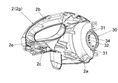
- the housing 2 has an accommodating portion 2a, a handle portion 2b, and a battery pack mounting portion 2c.
- the accommodating portion 2a is a portion corresponding to the front portion of the housing 2.
- the accommodating portion 2a accommodates the motor 6, the dust collecting fan 9, the fan guide 10, and the fan cover 20.
- the handle portion 2b is a portion extending rearward from the upper end portion of the accommodating portion 2a. The operator grips the handle portion 2b and handles the cleaner 1.
- An operation panel (switch portion) 5 is provided on the upper surface of the handle portion 2b. Various switches provided on the operation panel 5 can start and stop the cleaner 1 and switch the air volume of the cleaner 1.
- the battery pack mounting portion 2c is a portion corresponding to the lower rear portion of the housing 2.
- a battery pack 4 that serves as a power source for the cleaner 1 is detachably mounted on the battery pack mounting portion 2c.
- Exhaust ports 2e are provided on both left and right sides of the rear end of the housing 2.
- the housing 2 has a flange portion 2i protruding inward at the front end portion.
- the flange portion 2i is a plate-shaped portion perpendicular to the front-rear direction.
- the flange portion 2i is provided so as to go around the extension line of the rotating shaft 6a of the motor 6.
- the entire rotation shaft 6a and its extension line are also referred to as a “central axis”.
- the inner edge of the flange portion 2i is the opening edge of the intake port (housing intake port) 2d.
- the intake port 2d is a circular through hole centered on the central axis and penetrating in the extending direction of the rotating shaft 6a.
- the intake port 2d is formed so as to straddle the left housing 2f and the right housing 2g.
- the intake port 2d communicates with the space inside the dust case 3.
- the front of the intake port 2d is covered with the filter member 40.
- the motor 6 is a well-known electric motor with a brush.
- the motor 6 is configured as a unit including a motor case and bearings.
- the motor 6 operates on the power supplied from the battery pack 4.
- the rear end portion of the motor 6 is supported by the housing 2 via an elastic body 7 for vibration isolation.
- a dust collecting fan 9 is attached to the rotating shaft 6a of the motor 6.
- the dust collecting fan 9 rotates integrally with the rotating shaft 6a around the rotating shaft 6a.
- the rotating shaft 6a is also the central shaft of the dust collecting fan 9.
- the dust collecting fan 9 is a centrifugal fan.
- the dust collecting fan 9 is housed in an internal space formed by the fan guide 10 and the fan cover 20.
- the outer diameters of the fan guide 10 and the fan cover 20 are larger than the outer diameter of the dust collecting fan 9.
- the outer diameter of the dust collecting fan 9 is larger than the outer diameter of the motor case.
- Both the fan guide 10 and the fan cover 20 are, for example, resin molded bodies.
- the fan guide 10 is fixed to the front surface of the motor 6 by screwing or the like.
- the fan cover 20 is fixed and integrated with the fan guide 10 by claw engagement or the like.
- the fan guide 10 is located behind the dust collecting fan 9.
- the fan guide 10 has a vent (not shown) for passing the air flow generated by the dust collecting fan 9.
- the fan cover 20 has a cylindrical shape centered on the rotation shaft 6a.
- the rear end of the fan cover 20 is open.
- the front end of the fan cover 20 is not open except for the intake port (fan cover intake port) 21. That is, the intake port 21 is provided on the front surface of the fan cover 20.
- the intake port 21 is a circular through hole centered on the central axis and penetrating in the extending direction of the rotating shaft 6a. As shown in FIG.
- the fan cover 20 has a grid portion 22 that crosses the intake port 21 vertically and horizontally. As shown in FIG. 12, the lattice portion 22 projects forward from the opening surface of the intake port 21. The lattice portion 22 has a function of preventing a finger or a large foreign substance from entering the inside of the fan cover 20 from the intake port 21.
- a part of the front surface of the fan cover 20 is an inclined surface 23. The inclined surface 23 is provided so as to surround the entire circumference of the intake port 21.
- the sealing member 30 seals (closes airtightly) between the housing 2 and the fan cover 20. Specifically, the seal member 30 comes into contact with the inside of the intake port 2d in the housing 2 and the outside of the intake port 21 in the fan cover 20, so that the housing 2 and the fan cover 20 are between the intake port 2d and the intake port 21. Seal the inside and outside of the car to prevent air from passing through.
- the seal member 30 also has an anti-vibration function.
- the seal member 30 is an elastic body such as rubber.
- the seal member 30 is formed in an annular shape centered on the central axis, and the intake port 2d and the intake port 21 communicate with each other through a hole provided in the center of the seal member 30 as a communication passage.
- the seal member 30 is arranged around the intake port 21.
- the outer diameter of the seal member 30 is smaller than the outer diameter of the fan cover 20.
- the outer diameter of the sealing member 30 is larger than the outer diameter of the elastic body 7.
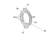
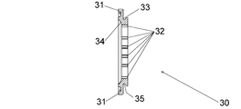
- the seal member 30 includes a first rotation regulating portion 31, a second rotation regulating portion 32, a first sealing portion 33, and a second sealing portion 34.
- the first rotation restricting portion 31 is a convex portion protruding outward from the outer peripheral surface of the seal member 30.
- the first rotation control unit 31 is provided at the upper part and the lower part of the seal member 30, respectively.
- the housing 2 has a detent portion 2h that sandwiches the first rotation restricting portion 31 from both the left and right sides. In the process of combining the left housing 2f and the right housing 2g, the first rotation restricting portion 31 is sandwiched by the detent portion 2h. The relative rotation of the seal member 30 with respect to the housing 2 is restricted by the engagement between the first rotation restricting portion 31 and the detent portion 2h.
- the second rotation restricting portion 32 is a recess, for example, a groove portion extending in the central axis direction formed on the inner peripheral surface (inner peripheral portion) of the seal member 30.
- a plurality of second rotation restricting units 32 are provided in the circumferential direction about the central axis.
- the second rotation restricting portion 32 is provided along the opening of the intake port 21 when viewed from the front. As shown in FIG. 4, the end portion of the grid portion 22 fits into each of the second rotation restricting portions 32.
- the relative rotation of the seal member 30 with respect to the fan cover 20 is restricted by the fitting (engagement) between the second rotation regulating portion 32 and the grid portion 22.
- the first seal portion 33 is a surface facing the front of the seal member 30.
- the first seal portion 33 comes into surface contact with the rear surface of the flange portion 2i over the entire circumference in the circumferential direction centered on the central axis.
- the seal member 30 receives a forward pressing force from the fan cover 20. By this pressing force, the first seal portion 33 is pressed against the rear surface of the flange portion 2i. As a result, the airtightness between the seal member 30 and the housing 2 is ensured.
- a groove portion (neck portion) 35 that goes around the central axis is provided on the outer peripheral surface of the seal member 30.
- the first seal portion 33 may include a groove portion 35.
- the fitting portion between the groove portion 35 and the flange portion 2i also contributes to ensuring the airtightness between the seal member 30 and the housing 2.
- the second seal portion 34 is a surface facing the rear of the seal member 30.
- the second seal portion 34 is an inclined surface inclined with respect to a surface perpendicular to the central axis direction.
- the second seal portion 34 extends rearward while expanding from the rear end of the inner peripheral surface on which the second rotation restricting portion 32 is formed.
- the second seal portion 34 comes into surface contact with the inclined surface 23 of the fan cover 20 over the entire circumference in the circumferential direction centered on the central axis.
- the inclined surface 23 is pressed against the second seal portion 34 by the forward pressing force applied from the fan cover 20 to the seal member 30. As a result, the airtightness between the seal member 30 and the fan cover 20 is ensured.
- the position of the second rotation restricting unit 32 in the radial direction around the central axis (hereinafter, simply referred to as “diameter direction”) is located on the central axis side of the first seal unit 33.
- the first seal portion 33 is provided within the arrangement range of the second rotation restricting portion 32 in the central axis direction.
- the first seal portion 33 may be provided outside the arrangement range of the second rotation restricting portion 32 in the central axis direction, but even in that case, it is preferable that the first seal portion 33 is provided within the arrangement range of the second seal portion 34 in the central axis direction. ..
- the positions of the first seal portion 33 and the second seal portion 34 are different from each other in the central axis direction.
- the first seal portion 33 is located on the front side of the second seal portion 34 in the central axis direction.
- the first seal portion 33 is formed inside the outer edge (outer edge substantially perpendicular to the radial direction) of the first rotation restricting portion 31 in the radial direction.
- the first seal portion 33 is formed so as to be located in the vicinity of the first rotation restricting portion 31 in the central axis direction.
- the second rotation restricting portion 32 and the first sealing portion 33 are arranged so that their positions in the central axis direction overlap.
- the dust collecting fan 9 When the operator operates the switch on the operation panel 5 to drive the motor 6, the dust collecting fan 9 is rotated by the driving force of the motor 6. The airflow generated by the dust collecting fan 9 is taken into the dust case 3 from the intake port 3a. The air flow passes through the filter member 40 and is taken into the fan cover 20 from the intake ports 2d and 21. The airflow is sucked into the inside of the dust collecting fan 9 and discharged to the outside, guided by the fan cover 20, and exits rearward from a vent of the fan guide 10 (not shown). The airflow is finally exhausted from the exhaust port 2e to the outside of the housing 2. Dust that has entered from the intake port 3a together with the air flow is collected by the filter member 40 and collects inside the dust case 3 and outside the filter member 40. The presence of the seal member 30 prevents airflow from circulating inside and outside the fan cover 20. As a result, the suction efficiency from the intake port 3a is enhanced.
- the seal member 30 has a smaller diameter than the fan cover 20. Therefore, the seal member 30 can be made smaller and lighter than a large seal member that covers up to the outer peripheral surface of the fan cover 20. Therefore, it is possible to suppress an increase in size, weight, and manufacturing cost of the entire product.
- the seal member 30 not only improves the suction force by the seal, but also functions as a vibration-proof member. Therefore, as compared with the case where the anti-vibration member is provided separately from the seal member, the number of parts can be reduced, and the suction force and the anti-vibration property can be improved with a simple structure. Further, since the fan motor unit including the motor 6, the dust collecting fan 9, the fan guide 10 and the fan cover 20 is supported by the housing 2 only by the elastic body 7 made of an elastic body such as rubber and the seal member 30, the fan motor The vibration generated in the unit is suppressed from being transmitted to the housing 2.
- the first seal portion 33 is pressed against the rear surface of the flange portion 2i, and the inclined surface 23 is pressed against the second seal portion 34 by the forward pressing force applied from the fan cover 20 to the seal member 30. That is, the seal member 30 is sandwiched between the fan cover 20 and the flange portion 2i from the front-rear direction.
- the flange portion 2i is fitted into the groove portion 35, and the sealing member 30 is sandwiched between the left housing 2f and the right housing 2g from the left-right direction.
- the second rotation regulating unit 32 regulates the relative rotation of the seal member 30 with respect to the fan cover 20 by engaging with the grid unit 22.
- the grid portion 22 prevents the entry of fingers and foreign matter from the intake port 21. Therefore, in order to regulate the relative rotation of the seal member 30 with respect to the fan cover 20, it is not necessary to separately add a configuration for preventing rotation on the fan cover 20 side. Therefore, the complexity of the configuration can be suppressed.
- Embodiment 2 The second embodiment of the present invention will be described with reference to FIGS. 14 to 18. This embodiment also relates to a cleaner. Hereinafter, the differences from the first embodiment will be mainly described, and the common points with the first embodiment will be omitted as appropriate.
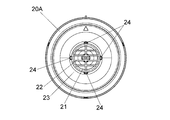
- the seal member 30A and the fan cover 20A replace the seal member 30 and the fan cover 20 of the first embodiment.
- the seal member 30A eliminates the second rotation regulation unit 32 of the seal member 30 and provides a second rotation regulation unit 32A instead.
- the second rotation restricting portion 32A is a hole provided on the rear surface of the seal member 30A, preferably a non-through hole.
- the second rotation restricting unit 32A is provided at intervals of 90 ° in the circumferential direction about the central axis.
- the fan cover 20A has the same number of convex portions (locking portions) 24 as the second rotation restricting portion 32A around the intake port 21. The position of the convex portion 24 in the circumferential direction about the central axis coincides with the second rotation restricting portion 32A.
- the convex portion 24 fits into the second rotation restricting portion 32A.
- the relative rotation of the seal member 30A with respect to the fan cover 20A is restricted by the fitting (engagement) between the convex portion 24 and the second rotation restricting portion 32A.
- the rib 22 does not project forward from the opening surface of the intake port 21, but may project as in the case of the first embodiment.
- the convex portion 24 is required on the fan cover 20 side as a configuration for preventing rotation, the same effect as that of the first embodiment can be obtained in other respects.
- the third embodiment of the present invention will be described with reference to FIGS. 19 to 22.
- This embodiment also relates to a cleaner.
- the differences from the first embodiment will be mainly described, and the common points with the first embodiment will be omitted as appropriate.
- the seal member 30B replaces the seal member 30 of the first embodiment.
- the seal member 30B has a hole (cavity) 36 on the rear surface.
- the hole 36 is preferably a non-through hole.
- a large number (16 in the illustrated example) of holes 36 are preferably provided at equal intervals in the circumferential direction about the central axis.
- the hole portion 36 is located between the first rotation restricting portion 31 and the second rotation regulating portion 32 in the radial direction.
- the hole portion 36 has a function of increasing the flexibility of the seal member 30B, that is, a function of facilitating elastic deformation of the seal member 30B. According to the present embodiment, the flexibility of the seal member 30B is increased, so that the anti-vibration effect of the seal member 30B is enhanced.
- the cleaner of the present invention may be a cyclone type or a corded type that operates with power supplied from an external AC power source.
- the motor may be a brushless motor.
Landscapes
- Engineering & Computer Science (AREA)
- Mechanical Engineering (AREA)
- General Engineering & Computer Science (AREA)
- Structures Of Non-Positive Displacement Pumps (AREA)
- Electric Suction Cleaners (AREA)
Abstract
簡単な構造で吸引力の向上や防振性の向上が可能なクリーナを提供する。クリーナ1において、集塵ファン9は、モータ6の駆動力により、中心軸を中心に回転する。シール部材30は、中心軸を中心とする円環状であり、吸気口21と吸気口2dとを連通するようにハウジング2とファンカバー20との間をシールする。シール部材30の外径は、ファンカバー20の外径よりも小さい。シール部材30の第1回転規制部31は、ハウジング2と係合して相対回転を規制する。第1シール部33は、中心軸を中心とする周方向の全周に渡ってハウジング2のフランジ部2iと当接する。第2回転規制部32は、ファンカバー20の格子部22と契合して相対回転を規制する。第2シール部34は、周方向の全周に渡ってファンカバー20と接する。第2回転規制部32は、中心軸を中心とする径方向における位置が第1シール部33よりも中心軸側に位置する。
Description
本発明は、モータにより駆動されるファンを備えるクリーナに関する。
下記特許文献1は、クリーナを開示する。このクリーナは、ファンを覆うようにファンカバーを備える。ファンカバーはモータに対して固定される。モータは、ファンカバーを介して本体ハウジングに保持される。
クリーナには、吸引力の向上や、モータやファンに生じる振動に対する防振性が求められる。吸引力の向上のために、ファンカバーと本体ハウジングとの間のシール材を設けることが考えられる。また、防振性を向上させるために、ファンカバーと本体ハウジングとの間に防振部材を介在させることが考えられる。一方で、シール材と防振部材との両方を設けることは、構造の複雑化により、製品全体の大型化や重量の増加、製造コストの増加などを招く恐れがある。
本発明の目的は、簡単な構造で吸引力の向上や防振性の向上が可能なクリーナを提供することである。
本発明のある態様は、クリーナである。このクリーナは、モータと、前記モータの駆動力により、中心軸を中心に回転するファンと、前記モータに対して固定され、前記ファンを内部に収容するファンカバーと、前記モータ及び前記ファンカバーを内部に収容するハウジングと、前記中心軸を中心とする円環状に形成されて、前記ハウジングと前記ファンカバーとの間をシールするシール部材と、を備え、前記ハウジングは、前記ハウジングの内外を前記中心軸の軸方向に貫通し、前記ファンの駆動時に前記ハウジング外部から内部へ向かう空気の流路となるハウジング吸気口を備え、前記ファンカバーは、前記ファンカバーの内外を前記軸方向に貫通し、前記ファンの駆動時に前記ハウジング吸気口から進入して前記ファンカバー内部へ向かう空気の流路となるファンカバー吸気口を備え、前記シール部材は、前記ファンカバー吸気口と前記ハウジング吸気口とを連通するように前記ハウジングと前記ファンカバーとの間をシールし、前記中心軸を中心とする外径が前記ファンカバーの外径よりも小さく、前記シール部材は、前記ハウジングと係合して相対回転を規制する第1回転規制部と、前記中心軸を中心とする周方向全周にわたって前記ハウジングと接する第1シール部と、前記ファンカバーと係合して相対回転を規制する第2回転規制部と、前記中心軸を中心とする周方向全周にわたって前記ファンカバーと接する第2シール部と、を備え、前記第2回転規制部は、前記中心軸を中心とする径方向における位置が前記第1シール部よりも前記中心軸側に位置する。
前記軸方向における前記第2回転規制部及び前記第2シール部の配置範囲内に、前記第1シール部が設けられてもよい。
前記第1シール部と前記第2シール部とは、前記軸方向に異なる位置に配置されてもよい。
前記第1シール部は、前記軸方向において前記第2シール部の前方側に配置され、前記第1シール部は、前記軸方向の前方側に臨む面であり、前記第2シール部は、前記軸方向の後方側に臨む面であってもよい。
前記第2シール部は、前記軸方向と垂直な面に対して傾斜した面であってもよい。
前記第1シール部は、前記径方向において第1回転規制部の外縁よりも内側に形成されてもよい。
前記第1シール部は、前記軸方向において第1回転規制部の近傍に位置するように形成されてもよい。
前記第2回転規制部と前記第1シール部は前記軸方向における位置が重なるように配置されてもよい。
前記第2回転規制部は、前記ファンカバー吸気口の開口部に沿って複数形成されてもよい。
前記ファンカバーは、前記ファンカバー吸気口の開口部を横切る格子部を有し、第2回転規制部は、前記シール部材の内周部に設けられて前記格子部の一部が嵌まる凹部であってもよい。
前記径方向における前記第1回転規制部と前記第2回転規制部との間に穴部が形成されてもよい。
前記ファンカバーの外径が前記ファンの外径よりも大きく、前記ファンの外径が前記モータのケースの外径よりも大きくてもよい。
前記ハウジングは、第1部品と第2部品とからなる左右二つ割り構造であり、前記ハウジング吸気口は、前記第1部品および前記第2部品に跨って形成され、前記シール部材は、前記ハウジング吸気口の内縁に当接するように前記第1部品と第2部品とに挟持されてもよい。
前記シール部材は、前記第1回転規制部が前記第1部品と前記第2部品とに挟持されることで、前記ハウジングに対する相対回転が規制されてもよい。
なお、以上の構成要素の任意の組合せ、本発明の表現を方法やシステムなどの間で変換したものもまた、本発明の態様として有効である。
本発明によれば、簡単な構造で吸引力の向上や防振性の向上が可能なクリーナを提供することができる。
以下において、各図面に示される同一または同等の構成要素、部材等には同一の符号を付し、適宜重複した説明は省略する。実施の形態は、発明を限定するものではなく例示である。実施の形態に記述されるすべての特徴やその組み合わせは、必ずしも発明の本質的なものであるとは限らない。
(実施の形態1) 図1~図13を参照し、本発明の実施の形態1を説明する。本実施の形態は、クリーナ1に関する。クリーナ1は、コードレス型かつ携帯型の非サイクロン式の電気掃除機である。図1及び図4により、クリーナ1における互いに直交する前後、上下、左右の各方向を定義する。前後方向は、モータ6の回転軸6aと平行な方向である。左右方向は、クリーナ1を前方から見た場合を基準に定義する。
クリーナ1の外殻は、ハウジング2及びダストケース3によって構成される。ハウジング2及びダストケース3は、共に例えば樹脂成形体である。ダストケース3は、ハウジング2の前方に着脱可能に接続、固定される。ダストケース3の前端部には、吸気口(ダストケース吸気口)3aが設けられる。吸気口3aには、図示しない延長管あるいはフレキシブルホースを取付け可能である。ダストケース3の内部には、フィルタ部材40が着脱可能に装着される。図4に示すように、ハウジング2は、左右二つ割り構造である。すなわち、ハウジング2は、互いに別部品である左ハウジング(第1部品)2fと右ハウジング(第2部品)2gとをネジ止め等により互いに固定、一体化したものである。
ハウジング2は、収容部2aと、ハンドル部2bと、電池パック装着部2cと、を有する。収容部2aは、ハウジング2の前部にあたる部分である。収容部2aは、モータ6、集塵ファン9、ファンガイド10及びファンカバー20を収容する。ハンドル部2bは、収容部2aの上端部から後方に延びる部分である。作業者は、ハンドル部2bを握ってクリーナ1を取り回す。ハンドル部2bの上面には、操作パネル(スイッチ部)5が設けられる。操作パネル5に設けられた各種スイッチにより、クリーナ1の起動、停止やクリーナ1の風量を切替え可能である。電池パック装着部2cは、ハウジング2の後下部にあたる部分である。電池パック装着部2cには、クリーナ1の電源となる電池パック4が着脱可能に装着される。ハウジング2の後端部の左右両側面に、それぞれ排気口2eが設けられる。
ハウジング2は、前端部に、内向きに突出するフランジ部2iを有する。フランジ部2iは、前後方向と垂直な板状部である。フランジ部2iは、モータ6の回転軸6aの延長線を一周するように設けられる。以下、回転軸6a及びその延長線を合わせた全体を「中心軸」とも表記する。フランジ部2iの内縁は、吸気口(ハウジング吸気口)2dの開口縁である。吸気口2dは、中心軸を中心とし、回転軸6aの延出方向に貫通する円形の貫通穴である。吸気口2dは、左ハウジング2f及び右ハウジング2gに跨がって形成される。吸気口2dは、吸気口2dは、ダストケース3内の空間と連通する。吸気口2dの前方は、フィルタ部材40に覆われる。
モータ6は、周知のブラシ付き電動モータである。モータ6は、モータケースや軸受を含むユニットとして構成される。モータ6は、電池パック4からの供給電力で動作する。モータ6の後端部は、防振用の弾性体7を介してハウジング2に支持される。モータ6の回転軸6aには、集塵ファン9が取り付けられる。集塵ファン9は、回転軸6aを中心に回転軸6aと一体に回転する。回転軸6aは、集塵ファン9の中心軸でもある。集塵ファン9は、遠心ファンである。集塵ファン9は、ファンガイド10及びファンカバー20によって形成される内部空間に収容される。ファンガイド10及びファンカバー20の外径は、集塵ファン9の外径よりも大きい。集塵ファン9の外径は、モータケースの外径よりも大きい。ファンガイド10及びファンカバー20は、共に例えば樹脂成形体である。
ファンガイド10は、モータ6の前面にネジ止め等により固定される。ファンカバー20は、ファンガイド10に爪係合等により固定、一体化される。ファンガイド10は、集塵ファン9の後方に位置する。ファンガイド10は、集塵ファン9の発生する気流を通過させる図示しない通気口を有する。ファンカバー20は、回転軸6aを中心とする円筒形状である。ファンカバー20の後端は開放である。ファンカバー20の前端は、吸気口(ファンカバー吸気口)21を除き非開放である。すなわち、ファンカバー20の前面に吸気口21が設けられる。吸気口21は、中心軸を中心とし、回転軸6aの延出方向に貫通する円形の貫通穴である。図13に示すように、ファンカバー20は、吸気口21を上下及び左右に横切る格子部22を有する。図12に示すように、格子部22は、吸気口21の開口面から前方に突出している。格子部22は、吸気口21からファンカバー20の内部に指や大きな異物が入ることを防止する機能を有する。ファンカバー20の前面の一部は傾斜面23となっている。傾斜面23は、吸気口21の全周に渡って囲むように設けられる。
シール部材30は、ハウジング2とファンカバー20との間をシールする(気密に閉塞する)。具体的には、シール部材30は、ハウジング2における吸気口2dの内側及びファンカバー20における吸気口21の外側と当接することで、吸気口2dと吸気口21の間においてハウジング2及びファンカバー20の内外を空気が通過できないようにシールする。シール部材30は、防振機能も有する。シール部材30は、ゴム等の弾性体である。シール部材30は、中心軸を中心とする円環状に形成されており、シール部材30の中心に設けられる穴を連通路として、吸気口2dと吸気口21が連通する。シール部材30は、吸気口21の周囲に配置される。シール部材30の外径は、ファンカバー20の外径よりも小さい。シール部材30の外径は、弾性体7の外径よりも大きい。シール部材30は、第1回転規制部31と、第2回転規制部32と、第1シール部33と、第2シール部34と、を含む。
第1回転規制部31は、シール部材30の外周面から外方に突出する凸部である。第1回転規制部31は、シール部材30の上部及び下部にそれぞれ設けられる。ハウジング2は、第1回転規制部31を左右両側から挟み込む回り止め部2hを有する。左ハウジング2fと右ハウジング2gとを組み合わせる過程で、第1回転規制部31が回り止め部2hにより挟持される。第1回転規制部31と回り止め部2hとの係合により、ハウジング2に対するシール部材30の相対回転が規制される。
第2回転規制部32は、シール部材30の内周面(内周部)に形成された、中心軸方向に延びる凹部、例えば溝部である。第2回転規制部32は、中心軸を中心とする周方向に複数設けられる。第2回転規制部32は、前方から見て、吸気口21の開口部に沿って設けられる。図4に示すように、各々の第2回転規制部32に、格子部22の端部が嵌まる。第2回転規制部32と格子部22との嵌合(係合)により、ファンカバー20に対するシール部材30の相対回転が規制される。
第1シール部33は、シール部材30の前方に臨む面である。第1シール部33は、中心軸を中心とする周方向全周に渡ってフランジ部2iの後面と面接触する。シール部材30は、ファンカバー20から、前方への押圧力を受ける。この押圧力により、第1シール部33がフランジ部2iの後面に押しつけられる。これにより、シール部材30とハウジング2との間の気密性が確保される。シール部材30の外周面には、中心軸回りに一周する溝部(くびれ部)35が設けられる。左ハウジング2f及び右ハウジング2gを組み合わせる過程で溝部35にフランジ部2iが嵌まり、シール部材30が左ハウジング2f及び右ハウジング2gに挟持される。この状態で、フランジ部2iの内縁が、溝部35の底面と当接する。第1シール部33は、溝部35を含んでもよい。溝部35とフランジ部2iの嵌合部も、シール部材30とハウジング2との間の気密性の確保に寄与する。
第2シール部34は、シール部材30の後方に臨む面である。第2シール部34は、中心軸方向と垂直な面に対して傾斜した傾斜面である。第2シール部34は、第2回転規制部32が形成された内周面の後端から広がりながら後方に延びる。第2シール部34は、中心軸を中心とする周方向全周に渡ってファンカバー20の傾斜面23と面接触する。ファンカバー20からシール部材30に印加される前方への押圧力により、傾斜面23が第2シール部34に押しつけられる。これにより、シール部材30とファンカバー20との間の気密性が確保される。
第2回転規制部32は、中心軸を中心とする径方向(以下、単に「径方向」と表記)における位置が、第1シール部33よりも中心軸側に位置する。図9に示すように、第1シール部33は、中心軸方向における第2回転規制部32の配置範囲内に設けられる。第1シール部33は、中心軸方向における第2回転規制部32の配置範囲外に設けられてもよいが、その場合も中心軸方向における第2シール部34の配置範囲内に設けられるとよい。第1シール部33と第2シール部34は、中心軸方向における位置が互いに異なる。第1シール部33は、中心軸方向において、第2シール部34の前方側に位置する。第1シール部33は、径方向において第1回転規制部31の外縁(径方向と略垂直な外縁)よりも内側に形成される。第1シール部33は、中心軸方向において第1回転規制部31の近傍に位置するように形成される。第2回転規制部32と第1シール部33は、中心軸方向における位置が重なるように配置される。
作業者が操作パネル5のスイッチを操作してモータ6が駆動すると、モータ6の駆動力により集塵ファン9が回転する。集塵ファン9の発生する気流は、吸気口3aからダストケース3内に取り込まれる。気流は、フィルタ部材40を通過し、吸気口2d、21からファンカバー20内に取り込まれる。気流は、集塵ファン9の内側に吸い込まれて外側に排出され、ファンカバー20にガイドされてファンガイド10の図示しない通気口から後方に抜ける。気流は、最終的に排気口2eからハウジング2の外部に排気される。吸気口3aから気流と共に進入した塵埃は、フィルタ部材40に捕集され、ダストケース3の内部かつフィルタ部材40の外側に溜まる。シール部材30があることで、ファンカバー20の内側と外側とで気流が循環することが防止される。これにより、吸気口3aからの吸引効率が高められる。
本実施の形態によれば、下記の効果を奏することができる。
(1) シール部材30は、ファンカバー20よりも小径である。このため、シール部材30は、ファンカバー20の外周面まで覆うような大きなシール部材と比較して、小型かつ軽量にできる。よって、製品全体の大型化や重量の増加、製造コストの増加を抑制できる。
(2) シール部材30は、シールにより吸引力を向上させるだけでなく、防振部材としても機能する。このため、シール部材とは別に防振部材を設ける場合と比較して、部品点数を削減でき、簡単な構造で吸引力の向上や防振性の向上が可能となる。また、モータ6、集塵ファン9、ファンガイド10及びファンカバー20からなるファンモータユニットは、ゴム等の弾性体からなる弾性体7及びシール部材30のみによってハウジング2に支持されるため、ファンモータユニットに生じる振動がハウジング2に伝達されることが抑制される。
(3) ファンカバー20からシール部材30に印加される前方への押圧力により、第1シール部33がフランジ部2iの後面に押しつけられ、また傾斜面23が第2シール部34に押しつけられる。すなわち、シール部材30はファンカバー20とフランジ部2iとの間に前後方向から挟持される。一方、左ハウジング2f及び右ハウジング2gを組み合わせる過程で溝部35にフランジ部2iが嵌まり、シール部材30が左ハウジング2f及び右ハウジング2gに左右方向から挟持される。このように、シール部材30を前後方向及び左右方向から挟持することで、効果的なシールを実現できる。
(4) 第2回転規制部32は、格子部22との係合によりファンカバー20に対するシール部材30の相対回転を規制する。格子部22は、吸気口21からの指や異物の進入を防止するものである。このため、ファンカバー20に対するシール部材30の相対回転を規制するために、ファンカバー20側に回り止め用の構成を別途追加する必要がない。したがって、構成の複雑化を抑制できる。
(実施の形態2) 図14~図18を参照し、本発明の実施の形態2を説明する。本実施の形態も、クリーナに関する。以下、実施の形態1との相違点を中心に説明し、実施の形態1との共通点については適宜説明を省略する。シール部材30A及びファンカバー20Aは、実施の形態1のシール部材30及びファンカバー20に替わるものである。
シール部材30Aは、シール部材30の第2回転規制部32を無くし、替わりに第2回転規制部32Aを設けたものである。第2回転規制部32Aは、シール部材30Aの後面に設けられた穴、好ましくは非貫通穴である。第2回転規制部32Aは、中心軸を中心とする周方向に90°間隔で設けられる。ファンカバー20Aは、吸気口21の周囲に、第2回転規制部32Aと同数の凸部(係止部)24を有する。凸部24は、中心軸を中心とする周方向の位置が、第2回転規制部32Aと一致する。凸部24は、第2回転規制部32Aに嵌まる。凸部24と第2回転規制部32Aとの嵌合(係合)により、ファンカバー20Aに対するシール部材30Aの相対回転が規制される。ファンカバー20Aにおいて、リブ22は吸気口21の開口面から前方に突出していないが、実施の形態1の場合と同様に突出してもよい。本実施の形態では、ファンカバー20側に回り止め用の構成として凸部24を要するものの、その他の点では実施の形態1と同様の効果を奏することができる。
(実施の形態3) 図19~図22を参照し、本発明の実施の形態3を説明する。本実施の形態も、クリーナに関する。以下、実施の形態1との相違点を中心に説明し、実施の形態1との共通点については適宜説明を省略する。シール部材30Bは、実施の形態1のシール部材30に替わるものである。
シール部材30Bは、後面に穴部(空洞)36を有する。穴部36は、好ましくは非貫通穴である。穴部36は、中心軸を中心とする周方向に好ましくは等間隔で多数(図示の例では16個)設けられる。穴部36は、径方向において、第1回転規制部31と第2回転規制部32との間に位置する。穴部36は、シール部材30Bの柔軟性を高める機能、すなわちシール部材30Bの弾性変形を容易にする機能を有する。本実施の形態によれば、シール部材30Bの柔軟性が高められることで、シール部材30Bによる防振効果が高められる。
以上、実施の形態を例に本発明を説明したが、実施の形態の各構成要素や各処理プロセスには請求項に記載の範囲で種々の変形が可能であることは当業者に理解されるところである。例えば、本発明のクリーナは、サイクロン式であってもよいし、外部の交流電源からの供給電力で動作するコード付きタイプであってもよい。モータは、ブラシレスモータであってもよい。
1…クリーナ(電気掃除機)、2…ハウジング、2a…収容部、2b…ハンドル部、2c…電池パック装着部、2d…吸気口(ハウジング吸気口)、2e…排気口、2f…左ハウジング(第1部品)、2g…右ハウジング(第2部品)、2h…回り止め部、2i…フランジ部、3…ダストケース、3a…吸気口(ダストケース吸気口)、4…電池パック、5…操作パネル(スイッチ部)、6…モータ、6a…回転軸、7…弾性体、8…照明部、9…集塵ファン、10…ファンガイド、20,20A…ファンカバー、21…吸気口、22…格子部、23…傾斜面、24…凸部(係止部)、30,30A,30B…シール部材、31…第1回転規制部、32,32A…第2回転規制部、33…第1シール部、34…第2シール部、35…溝部(くびれ部)、36…穴部(空洞部)、40…フィルタ部材。
Claims (14)
- モータと、
前記モータの駆動力により、中心軸を中心に回転するファンと、
前記モータに対して固定され、前記ファンを内部に収容するファンカバーと、
前記モータ及び前記ファンカバーを内部に収容するハウジングと、
前記中心軸を中心とする円環状に形成されて、前記ハウジングと前記ファンカバーとの間をシールするシール部材と、を備え、
前記ハウジングは、前記ハウジングの内外を前記中心軸の軸方向に貫通し、前記ファンの駆動時に前記ハウジング外部から内部へ向かう空気の流路となるハウジング吸気口を備え、
前記ファンカバーは、前記ファンカバーの内外を前記軸方向に貫通し、前記ファンの駆動時に前記ハウジング吸気口から進入して前記ファンカバー内部へ向かう空気の流路となるファンカバー吸気口を備え、
前記シール部材は、前記ファンカバー吸気口と前記ハウジング吸気口とを連通するように前記ハウジングと前記ファンカバーとの間をシールし、前記中心軸を中心とする外径が前記ファンカバーの外径よりも小さく、
前記シール部材は、前記ハウジングと係合して相対回転を規制する第1回転規制部と、前記中心軸を中心とする周方向全周にわたって前記ハウジングと接する第1シール部と、前記ファンカバーと係合して相対回転を規制する第2回転規制部と、前記中心軸を中心とする周方向全周にわたって前記ファンカバーと接する第2シール部と、を備え、前記第2回転規制部は、前記中心軸を中心とする径方向における位置が前記第1シール部よりも前記中心軸側に位置する、クリーナ。 - 前記軸方向における前記第2回転規制部及び前記第2シール部の配置範囲内に、前記第1シール部が設けられる、請求項1に記載のクリーナ。
- 前記第1シール部と前記第2シール部とは、前記軸方向に異なる位置に配置される、請求項1又は2に記載のクリーナ。
- 前記第1シール部は、前記軸方向において前記第2シール部の前方側に配置され、
前記第1シール部は、前記軸方向の前方側に臨む面であり、
前記第2シール部は、前記軸方向の後方側に臨む面である、請求項1から3のいずれか一項に記載のクリーナ。 - 前記第2シール部は、前記軸方向と垂直な面に対して傾斜した面である、請求項4に記載のクリーナ。
- 前記第1シール部は、前記径方向において第1回転規制部の外縁よりも内側に形成される、請求項1から5のいずれか一項に記載のクリーナ。
- 前記第1シール部は、前記軸方向において第1回転規制部の近傍に位置するように形成される、請求項1から6のいずれか一項に記載のクリーナ。
- 前記第2回転規制部と前記第1シール部は前記軸方向における位置が重なるように配置される、請求項1から7のいずれか一項に記載のクリーナ。
- 前記第2回転規制部は、前記ファンカバー吸気口の開口部に沿って複数形成される、請求項1から8のいずれか一項に記載のクリーナ。
- 前記ファンカバーは、前記ファンカバー吸気口の開口部を横切る格子部を有し、
第2回転規制部は、前記シール部材の内周部に設けられて前記格子部の一部が嵌まる凹部である、請求項1から9のいずれか一項に記載のクリーナ。 - 前記径方向における前記第1回転規制部と前記第2回転規制部との間に穴部が形成される、請求項1から10のいずれか一項に記載のクリーナ。
- 前記ファンカバーの外径が前記ファンの外径よりも大きく、前記ファンの外径が前記モータのケースの外径よりも大きい、請求項1から11のいずれか一項に記載のクリーナ。
- 前記ハウジングは、第1部品と第2部品とからなる左右二つ割り構造であり、
前記ハウジング吸気口は、前記第1部品および前記第2部品に跨って形成され、
前記シール部材は、前記ハウジング吸気口の内縁に当接するように前記第1部品と第2部品とに挟持される、請求項1から12のいずれか一項に記載のクリーナ。 - 前記シール部材は、前記第1回転規制部が前記第1部品と前記第2部品とに挟持されることで、前記ハウジングに対する相対回転が規制される、請求項13に記載のクリーナ。
Priority Applications (2)
| Application Number | Priority Date | Filing Date | Title |
|---|---|---|---|
| JP2021561244A JP7315025B2 (ja) | 2019-11-27 | 2020-10-30 | クリーナ |
| CN202080082841.5A CN114727731B (zh) | 2019-11-27 | 2020-10-30 | 清洁器 |
Applications Claiming Priority (2)
| Application Number | Priority Date | Filing Date | Title |
|---|---|---|---|
| JP2019214789 | 2019-11-27 | ||
| JP2019-214789 | 2019-11-27 |
Publications (1)
| Publication Number | Publication Date |
|---|---|
| WO2021106493A1 true WO2021106493A1 (ja) | 2021-06-03 |
Family
ID=76129527
Family Applications (1)
| Application Number | Title | Priority Date | Filing Date |
|---|---|---|---|
| PCT/JP2020/040879 WO2021106493A1 (ja) | 2019-11-27 | 2020-10-30 | クリーナ |
Country Status (3)
| Country | Link |
|---|---|
| JP (1) | JP7315025B2 (ja) |
| CN (1) | CN114727731B (ja) |
| WO (1) | WO2021106493A1 (ja) |
Cited By (2)
| Publication number | Priority date | Publication date | Assignee | Title |
|---|---|---|---|---|
| JP2022100046A (ja) * | 2020-12-23 | 2022-07-05 | 株式会社マキタ | 送風機 |
| US11795967B2 (en) | 2020-12-23 | 2023-10-24 | Makita Corporation | Blower |
Citations (5)
| Publication number | Priority date | Publication date | Assignee | Title |
|---|---|---|---|---|
| JPH044690Y2 (ja) * | 1985-02-27 | 1992-02-12 | ||
| JPH04272733A (ja) * | 1991-02-28 | 1992-09-29 | Matsushita Electric Ind Co Ltd | 電動送風機の防振装置 |
| WO2014162773A1 (ja) * | 2013-04-01 | 2014-10-09 | 株式会社 マキタ | クリーナ |
| US20150184673A1 (en) * | 2014-01-02 | 2015-07-02 | Samsung Electronics Co., Ltd. | Fan motor assembly and vacuum cleaner having the same |
| JP2018068726A (ja) * | 2016-10-31 | 2018-05-10 | 日立工機株式会社 | 集塵装置 |
Family Cites Families (5)
| Publication number | Priority date | Publication date | Assignee | Title |
|---|---|---|---|---|
| JP4272733B2 (ja) | 1998-12-25 | 2009-06-03 | キヤノン株式会社 | 液晶組成物 |
| JP5598222B2 (ja) * | 2010-09-30 | 2014-10-01 | 株式会社アドヴィックス | 軸シール装置とそれを用いたポンプ装置及びブレーキ液圧制御装置 |
| JP2013141514A (ja) * | 2012-01-11 | 2013-07-22 | Hitachi Appliances Inc | 電気掃除機 |
| JP2013204784A (ja) * | 2012-03-29 | 2013-10-07 | Nippon Densan Corp | 軸受装置および送風ファン |
| US11303180B2 (en) * | 2017-02-14 | 2022-04-12 | Nidec Sankyo Corporation | Motor and pump device |
-
2020
- 2020-10-30 CN CN202080082841.5A patent/CN114727731B/zh active Active
- 2020-10-30 WO PCT/JP2020/040879 patent/WO2021106493A1/ja active Application Filing
- 2020-10-30 JP JP2021561244A patent/JP7315025B2/ja active Active
Patent Citations (5)
| Publication number | Priority date | Publication date | Assignee | Title |
|---|---|---|---|---|
| JPH044690Y2 (ja) * | 1985-02-27 | 1992-02-12 | ||
| JPH04272733A (ja) * | 1991-02-28 | 1992-09-29 | Matsushita Electric Ind Co Ltd | 電動送風機の防振装置 |
| WO2014162773A1 (ja) * | 2013-04-01 | 2014-10-09 | 株式会社 マキタ | クリーナ |
| US20150184673A1 (en) * | 2014-01-02 | 2015-07-02 | Samsung Electronics Co., Ltd. | Fan motor assembly and vacuum cleaner having the same |
| JP2018068726A (ja) * | 2016-10-31 | 2018-05-10 | 日立工機株式会社 | 集塵装置 |
Cited By (2)
| Publication number | Priority date | Publication date | Assignee | Title |
|---|---|---|---|---|
| JP2022100046A (ja) * | 2020-12-23 | 2022-07-05 | 株式会社マキタ | 送風機 |
| US11795967B2 (en) | 2020-12-23 | 2023-10-24 | Makita Corporation | Blower |
Also Published As
| Publication number | Publication date |
|---|---|
| CN114727731B (zh) | 2023-09-26 |
| JPWO2021106493A1 (ja) | 2021-06-03 |
| CN114727731A (zh) | 2022-07-08 |
| JP7315025B2 (ja) | 2023-07-26 |
Similar Documents
| Publication | Publication Date | Title |
|---|---|---|
| WO2021106493A1 (ja) | クリーナ | |
| KR100365478B1 (ko) | 전동송풍기 및 그것을 사용한 전기청소기 | |
| JP5068725B2 (ja) | ヘッジトリマ | |
| KR101259678B1 (ko) | 전기 진공 청소기 | |
| JP2009131329A (ja) | 電気掃除機 | |
| EP3450769A1 (en) | Motor module and vacuum cleaner | |
| US20190069741A1 (en) | Motor module and vacuum cleaner | |
| EP3449790A1 (en) | Motor module and vacuum cleaner | |
| JP2018064849A (ja) | モータモジュールおよび掃除機 | |
| JP2008212500A (ja) | 電気掃除機 | |
| JP7102277B2 (ja) | クリーナ | |
| CN106715922B (zh) | 离心式鼓风机及具备该离心式鼓风机的汽车 | |
| US11744419B2 (en) | Cleaner | |
| JPH11173298A (ja) | 電動送風機 | |
| WO2021117509A1 (ja) | クリーナ | |
| JP2001003898A (ja) | 電動送風機及びそれを用いた電気掃除機 | |
| JP2022112929A (ja) | 集じん機 | |
| JP2020178976A (ja) | クリーナ | |
| JP2022045844A (ja) | フィルタ装置及び作業機 | |
| KR20200076858A (ko) | 모터어셈블리 및 이를 포함하는 청소기 | |
| JP5368166B2 (ja) | 電気掃除機 | |
| JP3955705B2 (ja) | 電気掃除機 | |
| JP2021029599A (ja) | サイクロンユニット及びクリーナ | |
| JP2023132055A (ja) | 作業機 | |
| JP6216218B2 (ja) | 電気掃除機 |
Legal Events
| Date | Code | Title | Description |
|---|---|---|---|
| 121 | Ep: the epo has been informed by wipo that ep was designated in this application |
Ref document number: 20894559 Country of ref document: EP Kind code of ref document: A1 |
|
| ENP | Entry into the national phase |
Ref document number: 2021561244 Country of ref document: JP Kind code of ref document: A |
|
| NENP | Non-entry into the national phase |
Ref country code: DE |
|
| 122 | Ep: pct application non-entry in european phase |
Ref document number: 20894559 Country of ref document: EP Kind code of ref document: A1 |