WO2021106384A1 - セルスタック装置、モジュール、モジュール収容装置および金属部材 - Google Patents
セルスタック装置、モジュール、モジュール収容装置および金属部材 Download PDFInfo
- Publication number
- WO2021106384A1 WO2021106384A1 PCT/JP2020/038213 JP2020038213W WO2021106384A1 WO 2021106384 A1 WO2021106384 A1 WO 2021106384A1 JP 2020038213 W JP2020038213 W JP 2020038213W WO 2021106384 A1 WO2021106384 A1 WO 2021106384A1
- Authority
- WO
- WIPO (PCT)
- Prior art keywords
- end current
- cell stack
- cell
- current collector
- current collecting
- Prior art date
- Legal status (The legal status is an assumption and is not a legal conclusion. Google has not performed a legal analysis and makes no representation as to the accuracy of the status listed.)
- Ceased
Links
Images


Classifications
-
- H—ELECTRICITY
- H01—ELECTRIC ELEMENTS
- H01M—PROCESSES OR MEANS, e.g. BATTERIES, FOR THE DIRECT CONVERSION OF CHEMICAL ENERGY INTO ELECTRICAL ENERGY
- H01M8/00—Fuel cells; Manufacture thereof
- H01M8/02—Details
- H01M8/0202—Collectors; Separators, e.g. bipolar separators; Interconnectors
- H01M8/0204—Non-porous and characterised by the material
- H01M8/0206—Metals or alloys
- H01M8/0208—Alloys
- H01M8/021—Alloys based on iron
-
- H—ELECTRICITY
- H01—ELECTRIC ELEMENTS
- H01M—PROCESSES OR MEANS, e.g. BATTERIES, FOR THE DIRECT CONVERSION OF CHEMICAL ENERGY INTO ELECTRICAL ENERGY
- H01M8/00—Fuel cells; Manufacture thereof
- H01M8/02—Details
- H01M8/0202—Collectors; Separators, e.g. bipolar separators; Interconnectors
- H01M8/0204—Non-porous and characterised by the material
- H01M8/0223—Composites
- H01M8/0228—Composites in the form of layered or coated products
-
- H—ELECTRICITY
- H01—ELECTRIC ELEMENTS
- H01M—PROCESSES OR MEANS, e.g. BATTERIES, FOR THE DIRECT CONVERSION OF CHEMICAL ENERGY INTO ELECTRICAL ENERGY
- H01M8/00—Fuel cells; Manufacture thereof
- H01M8/02—Details
- H01M8/0202—Collectors; Separators, e.g. bipolar separators; Interconnectors
- H01M8/023—Porous and characterised by the material
- H01M8/0236—Glass; Ceramics; Cermets
-
- H—ELECTRICITY
- H01—ELECTRIC ELEMENTS
- H01M—PROCESSES OR MEANS, e.g. BATTERIES, FOR THE DIRECT CONVERSION OF CHEMICAL ENERGY INTO ELECTRICAL ENERGY
- H01M8/00—Fuel cells; Manufacture thereof
- H01M8/04—Auxiliary arrangements, e.g. for control of pressure or for circulation of fluids
-
- H—ELECTRICITY
- H01—ELECTRIC ELEMENTS
- H01M—PROCESSES OR MEANS, e.g. BATTERIES, FOR THE DIRECT CONVERSION OF CHEMICAL ENERGY INTO ELECTRICAL ENERGY
- H01M8/00—Fuel cells; Manufacture thereof
- H01M8/10—Fuel cells with solid electrolytes
- H01M8/12—Fuel cells with solid electrolytes operating at high temperature, e.g. with stabilised ZrO2 electrolyte
-
- H—ELECTRICITY
- H01—ELECTRIC ELEMENTS
- H01M—PROCESSES OR MEANS, e.g. BATTERIES, FOR THE DIRECT CONVERSION OF CHEMICAL ENERGY INTO ELECTRICAL ENERGY
- H01M8/00—Fuel cells; Manufacture thereof
- H01M8/24—Grouping of fuel cells, e.g. stacking of fuel cells
- H01M8/2465—Details of groupings of fuel cells
- H01M8/247—Arrangements for tightening a stack, for accommodation of a stack in a tank or for assembling different tanks
- H01M8/2475—Enclosures, casings or containers of fuel cell stacks
-
- H—ELECTRICITY
- H01—ELECTRIC ELEMENTS
- H01M—PROCESSES OR MEANS, e.g. BATTERIES, FOR THE DIRECT CONVERSION OF CHEMICAL ENERGY INTO ELECTRICAL ENERGY
- H01M8/00—Fuel cells; Manufacture thereof
- H01M8/24—Grouping of fuel cells, e.g. stacking of fuel cells
- H01M8/2465—Details of groupings of fuel cells
-
- Y—GENERAL TAGGING OF NEW TECHNOLOGICAL DEVELOPMENTS; GENERAL TAGGING OF CROSS-SECTIONAL TECHNOLOGIES SPANNING OVER SEVERAL SECTIONS OF THE IPC; TECHNICAL SUBJECTS COVERED BY FORMER USPC CROSS-REFERENCE ART COLLECTIONS [XRACs] AND DIGESTS
- Y02—TECHNOLOGIES OR APPLICATIONS FOR MITIGATION OR ADAPTATION AGAINST CLIMATE CHANGE
- Y02E—REDUCTION OF GREENHOUSE GAS [GHG] EMISSIONS, RELATED TO ENERGY GENERATION, TRANSMISSION OR DISTRIBUTION
- Y02E60/00—Enabling technologies; Technologies with a potential or indirect contribution to GHG emissions mitigation
- Y02E60/30—Hydrogen technology
- Y02E60/50—Fuel cells
-
- Y—GENERAL TAGGING OF NEW TECHNOLOGICAL DEVELOPMENTS; GENERAL TAGGING OF CROSS-SECTIONAL TECHNOLOGIES SPANNING OVER SEVERAL SECTIONS OF THE IPC; TECHNICAL SUBJECTS COVERED BY FORMER USPC CROSS-REFERENCE ART COLLECTIONS [XRACs] AND DIGESTS
- Y02—TECHNOLOGIES OR APPLICATIONS FOR MITIGATION OR ADAPTATION AGAINST CLIMATE CHANGE
- Y02P—CLIMATE CHANGE MITIGATION TECHNOLOGIES IN THE PRODUCTION OR PROCESSING OF GOODS
- Y02P70/00—Climate change mitigation technologies in the production process for final industrial or consumer products
- Y02P70/50—Manufacturing or production processes characterised by the final manufactured product
Definitions
- the present disclosure relates to cell stack devices, modules, module accommodating devices and metal members.
- a fuel cell composed of a plurality of fuel cell cells, which is a type of cell capable of obtaining electricity by using a fuel gas such as a hydrogen-containing gas and an oxygen-containing gas such as air.
- a fuel gas such as a hydrogen-containing gas and an oxygen-containing gas such as air.
- Various cell stack devices have been proposed.
- an end current collecting member made of a metal material is located at an end of the cell stack in the arrangement direction of a plurality of fuel cell cells (see Patent Document 1).
- the cell stack device includes a cell stack and an end current collecting member.
- a cell stack a plurality of cells are arranged.
- the end current collecting member is located at the end of the cell stack in the arrangement direction of the plurality of cells. Then, the surface of the end current collector member exposed to the oxidizing atmosphere is covered with a coating material containing manganese, and the surface of the end current collector member exposed to the reducing atmosphere is covered with a film different from the coating material. It is said.
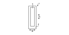
- FIG. 1A is a cross-sectional view showing an example of a cell according to an embodiment.
- FIG. 1B is a side view of an example of the cell according to the embodiment as viewed from the air electrode side.
- FIG. 1C is a side view of an example of the cell according to the embodiment as viewed from the interconnector side.
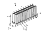
- FIG. 2A is a perspective view showing an example of the cell stack device according to the embodiment.
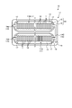
- FIG. 2B is a cross-sectional view taken along the line XX shown in FIG. 2A.
- FIG. 2C is a top view showing an example of the cell stack device according to the embodiment.
- FIG. 3 is a cross-sectional view showing an end current collector member according to the embodiment.
- FIG. 4 is a cross-sectional view showing an end current collecting member according to the first modification of the embodiment.
- FIG. 5 is a cross-sectional view showing an end current collecting member according to the second modification of the embodiment.
- FIG. 6 is a cross-sectional view showing an end current collecting member according to the third modification of the embodiment.
- FIG. 7 is an enlarged cross-sectional view showing an end current collector member according to a modified example 4 of the embodiment.
- FIG. 8 is an enlarged cross-sectional view showing an end current collector member according to a modified example 5 of the embodiment.
- FIG. 9 is an enlarged cross-sectional view showing an end current collector member according to a modified example 6 of the embodiment.
- FIG. 10 is a cross-sectional view showing an end current collector member according to a modified example 7 of the embodiment.
- FIG. 11 is a cross-sectional view showing an end current collecting member according to the modified example 8 of the embodiment.
- FIG. 12 is a cross-sectional view showing an end current collector member according to a modified example 9 of the embodiment.
- FIG. 13 is an external perspective view showing an example of the module according to the embodiment.
- FIG. 14 is an exploded perspective view schematically showing an example of the module accommodating device according to the embodiment.
- a fuel cell composed of a plurality of fuel cell cells, which is a type of cell capable of obtaining electricity by using a fuel gas such as a hydrogen-containing gas and an oxygen-containing gas such as air.
- a fuel gas such as a hydrogen-containing gas and an oxygen-containing gas such as air.
- Various cell stack devices have been proposed.
- an end current collecting member made of a metal material is located at an end of the cell stack in the arrangement direction of a plurality of fuel cell cells.
- FIG. 1A is a cross-sectional view showing an example of the cell 1 according to the embodiment
- FIG. 1B is a side view of an example of the cell 1 according to the embodiment as viewed from the air electrode 5 side
- FIG. 1C is a side view of the embodiment. It is a side view which took an example of the cell 1 which concerns on the above
- the cell 1 is a hollow flat plate type and has an elongated plate shape.
- the shape of the entire cell 1 viewed from the side surface is, for example, a side length of 5 cm to 50 cm in the length direction L, and a length W in the width direction orthogonal to the length direction L. Is a rectangle of 1 cm to 10 cm.
- the total thickness of the cell 1 (thickness direction T) is 1 mm to 5 mm.
- the cell 1 includes a conductive support substrate 2, an element portion, and an interconnector 6.
- the support substrate 2 is a columnar structure having a pair of opposing first flat surfaces n1, a second flat surface n2, and a pair of arcuate side surfaces m connecting the first flat surface n1 and the second flat surface n2. ..
- the element portion is located on the first flat surface n1 of the support substrate 2.
- Such an element unit has a fuel electrode 3, a solid electrolyte layer 4, and an air electrode 5.
- the interconnector 6 is located on the second flat surface n2 of the cell 1.
- the air electrode 5 does not extend to the lower end of the cell 1.
- the solid electrolyte layer 4 is exposed on the surface of the first flat surface n1.
- the interconnector 6 may extend to the lower end of the cell 1.
- the interconnector 6 and the solid electrolyte layer 4 are exposed on the surface.
- the solid electrolyte layer 4 is exposed on the surface of the pair of arcuate side surfaces m of the cell 1. The interconnector 6 does not have to extend to the lower end of the cell 1.
- the support substrate 2 has a gas flow path 2a through which gas flows.
- FIG. 1A shows an example having six gas flow paths 2a extending along the length direction.
- the support substrate 2 has gas permeability and allows fuel gas to permeate to the fuel electrode 3.
- the support substrate 2 shown in FIG. 1A has conductivity.
- the support substrate 2 collects electricity generated in the element portion via the interconnector 6.
- the material of the support substrate 2 contains, for example, an iron group metal component and an inorganic oxide.
- the iron group metal component of the material of the support substrate 2 may be, for example, Ni and / or NiO.
- the inorganic oxide in the material of the support substrate 2 may be, for example, a specific rare earth element oxide.
- the material of the fuel electrode 3 generally known materials can be used.
- porous conductive ceramics for example, ceramics containing ZrO 2 and Ni and / or NiO in which calcium oxide, magnesium oxide, or a rare earth element oxide is solid-dissolved, may be used. Good.
- the rare earth element oxide such as Y 2 O 3 is used.
- stabilized zirconia calcium oxide, magnesium oxide, or ZrO 2 to the oxide of the rare earth element in solid solution.
- stabilized zirconia also includes partially stabilized zirconia.
- the solid electrolyte layer 4 is an electrolyte and bridges ions between the fuel electrode 3 and the air electrode 5. At the same time, the solid electrolyte layer 4 has a gas blocking property and makes it difficult for a leak between the fuel gas and the oxygen-containing gas to occur.
- Material of the solid electrolyte layer 4 is, for example, ZrO 2 which rare earth oxide 3-15 mol% was dissolved.
- the rare earth element oxide such as Y 2 O 3 is used.
- other materials may be used as the material of the solid electrolyte layer 4.
- the material of the air electrode 5 is not particularly limited as long as it is generally used for the air electrode.
- the material of the air electrode 5 may be, for example, conductive ceramics such as a so-called ABO 3 type perovskite type oxide.
- the material of the air electrode 5 may be, for example, a composite oxide in which Sr and La coexist at the A site.
- a composite oxide La x Sr 1-x Co y Fe 1-y O 3, La x Sr 1-x MnO 3, La x Sr 1-x FeO 3, La x Sr 1-x CoO 3 and the like can be mentioned. Note that x is 0 ⁇ x ⁇ 1 and y is 0 ⁇ y ⁇ 1.
- the air electrode 5 has gas permeability.
- the open porosity of the air electrode 5 may be 20% or more, particularly in the range of 30% to 50%.
- a lanthanum chromite-based perovskite-type oxide (LaCrO 3- based oxide), a lanthanum strontium titanium-based perovskite-type oxide (LaSrTiO 3- based oxide), or the like may be used. These materials are conductive and are neither reduced nor oxidized when they come into contact with fuel gases such as hydrogen-containing gases and oxygen-containing gases such as air.
- the interconnector 6 is dense and makes it difficult for the fuel gas flowing through the gas flow path 2a located inside the support substrate 2 and the oxygen-containing gas flowing outside the support substrate 2 to leak.
- the interconnector 6 may have a relative density of 93% or more, particularly 95% or more.
- FIGS. 2A to 2C are perspective views showing an example of the cell stack device 10 according to the embodiment
- FIG. 2B is a cross-sectional view taken along the line AA shown in FIG. 2A
- FIG. 2C is a cell stack device according to the embodiment. It is a top view which shows an example of 10.
- the cell stack device 10 includes a cell stack 11 having a plurality of cells 1 arranged (stacked) in the thickness direction T of the cells 1 (see FIG. 1A), and a fixing member 12.
- the fixing member 12 has a fixing member 13 and a support member 14.
- the support member 14 supports the cell 1.
- the fixing material 13 fixes the cell 1 to the support member 14.
- the support member 14 has a support body 15 and a gas tank 16.
- the support 15 and the gas tank 16 which are the support members 14 are made of metal and have conductivity.
- the support 15 has an insertion hole 15a into which the lower ends of the plurality of cells 1 are inserted.
- the lower ends of the plurality of cells 1 and the inner walls of the insertion holes 15a are joined by a fixing material 13.
- the gas tank 16 has an opening for supplying reaction gas to a plurality of cells 1 through the insertion holes 15a, and a concave groove 16a located around the opening.
- the outer peripheral end of the support 15 is joined to the gas tank 16 by a joining material 21 filled in the concave groove 16a of the gas tank 16.
- the fuel gas is stored in the internal space 22 (see FIG. 2B) formed by the support 15 which is the support member 14 and the gas tank 16.
- a gas flow pipe 20 is connected to the gas tank 16.
- the fuel gas is supplied to the gas tank 16 through the gas flow pipe 20, and is supplied from the gas tank 16 to the gas flow path 2a (see FIG. 1A) inside the cell 1.
- the fuel gas supplied to the gas tank 16 is generated by the reformer 82 (see FIG. 13) described later.
- Hydrogen-rich fuel gas can be generated by steam reforming the raw fuel.
- the fuel gas contains steam.
- FIG. 2A includes two rows of cell stacks 11, two supports 15, and a gas tank 16.
- Each of the two rows of cell stacks 11 has a plurality of cells 1.
- Each cell stack 11 is fixed to each support 15.
- the gas tank 16 has two through holes on the upper surface.
- Each support 15 is arranged in each through hole.
- the internal space 22 is formed by one gas tank 16 and two supports 15.
- the shape of the insertion hole 15a is, for example, an oval shape when viewed from above.
- the length of the cell 1 in the arrangement direction, that is, the thickness direction T is larger than the distance between the two end current collecting members 17 located at both ends of the cell stack 11.
- the width of the insertion hole 15a is, for example, larger than the length of the cell 1 in the width direction W (see FIG. 1A).
- the joint portion between the inner wall of the insertion hole 15a and the lower end portion of the cell 1 is filled with the fixing material 13 and solidified.
- the inner wall of the insertion hole 15a and the lower end portions of the plurality of cells 1 are joined and fixed, respectively, and the lower end portions of the cell 1 are joined and fixed to each other.
- the gas flow path 2a of each cell 1 communicates with the internal space 22 of the support member 14 at the lower end portion.
- the fixing material 13 and the joining material 21 those having low conductivity can be used.
- a specific material of the fixing material 13 and the bonding material 21 amorphous glass or the like may be used, and in particular, crystallized glass or the like may be used.
- the crystallized glass for example, SiO 2 -CaO-based, MgO-B 2 O 3 based, La 2 O 3 -B 2 O 3 -MgO based, La 2 O 3 -B 2 O 3 -ZnO system, SiO 2 it may be used any of materials such as -CaO-ZnO-based, may be especially a material of SiO 2 -MgO system.
- the end current collecting member 17 is connected to the outermost cell 1 in the arrangement direction of the plurality of cells 1.
- the end current collecting member 17 is connected to a conductive portion 19 projecting to the outside of the cell stack 11.
- the conductive portion 19 has a function of collecting electricity generated by the power generation of the cell 1 and drawing it out to the outside.
- the end current collecting member 17, the conductive member 18, and the conductive portion 19 are not shown.
- the conductive portion 19 of the cell stack device 10 is divided into a positive electrode terminal 19A, a negative electrode terminal 19B, and a connection terminal 19C.
- the positive electrode terminal 19A functions as a positive electrode when the electric power generated by the cell stack 11 is output to the outside, and is electrically connected to the end current collecting member 17 on the positive electrode side of the cell stack 11A.
- the negative electrode terminal 19B functions as a negative electrode when the electric power generated by the cell stack 11 is output to the outside, and is electrically connected to the end current collecting member 17 on the negative electrode side of the cell stack 11B.
- connection terminal 19C electrically connects the negative electrode side end current collecting member 17 in the cell stack 11A and the positive electrode side end current collecting member 17 in the cell stack 11B.
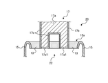
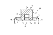
- FIG. 3 is a cross-sectional view showing an end current collecting member 17 according to the embodiment.
- the end current collecting member 17 is an example of a metal member.
- one end (lower end in the drawing) of the end current collecting member 17 is inserted into the insertion hole 15a together with a plurality of cells 1 (see FIG. 2B), and a fixing material is inserted in the insertion hole 15a. It is fixed at 13. That is, the side surface at one end (lower end) of the end current collector 17 is in contact with the fixing member 13.
- the internal space 22 is a space in which the fuel electrode 3 of the cell 1 contacts through the support substrate 2, and is filled with a fuel gas such as a hydrogen-containing gas. That is, the internal space 22 is a reducing atmosphere.
- the external space 23 is a space where the air electrode 5 of the cell 1 is exposed, and is filled with an oxygen-containing gas such as air. That is, the external space 23 is an oxidizing atmosphere.
- the end current collecting member 17 used in such an environment may have a surface exposed to an oxidizing atmosphere (external space 23) covered with a covering material 17b.
- the material of the coating material 17b is, for example, a conductive oxide containing manganese (Mn) (for example, ZnMnCoO 4 ).
- the covering material 17b is formed on the surface of the base material 17a by, for example, electrodeposition coating.
- the material of the base material 17a of the end current collecting member 17 is, for example, stainless steel.
- the durability of the end current collecting member 17 can be improved.
- the surface (bottom surface in the figure) of the end current collecting member 17 exposed to the reducing atmosphere (internal space 22) is covered with a film different from the covering material 17b.
- the surface exposed to the reducing atmosphere is covered with the natural oxide film 17a1 of the base material 17a.
- the material of such a natural oxide film 17a1 is, for example, chromium oxide (Cr 2 O 3 ).
- the constituent elements of the natural oxide film 17a1 hardly cause a reduction reaction even in a reducing atmosphere.
- the durability of the end current collecting member 17 can be increased, so that the durability of the cell stack device 10 can be increased.
- a predetermined portion (here, the bottom surface) is etched with sulfuric acid or the like, and the exposed surface of the base material 17a is oxidized. It can be formed by high temperature treatment inside.
- the end current collecting member 17 can be manufactured at low cost by covering the surface exposed to the reducing atmosphere with a naturally formable oxide film 17a1.
- FIG. 4 is a cross-sectional view showing an end current collecting member 17 according to the first modification of the embodiment.
- the surface exposed to the reducing atmosphere may be covered with the reduction preventing film 17c.
- the material of the reduction prevention film 17c is a material in which the constituent elements hardly cause a reduction reaction even in a reducing atmosphere, and is, for example, forsterite, alumina (Al 2 O 3 ), and the like.
- the durability of the end current collecting member 17 can be increased, so that the durability of the cell stack device 10 can be increased.
- the first modification since a material other than stainless steel can be used for the base material 17a of the end current collector member 17, high performance of the end current collector member 17 (for example, improvement of electrical conductivity) is realized. can do.
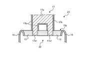
- FIG. 5 is a cross-sectional view showing an end current collecting member 17 according to the second modification of the embodiment.
- the surface in contact with the fixing material 13 is also a film different from the covering material 17b. It is covered.
- the surface exposed to the reducing atmosphere and the surface in contact with the fixing material 13 are covered with the natural oxide film 17a1 of the base material 17a.
- the durability of the end current collecting member 17 can be further enhanced, so that the durability of the cell stack device 10 can be further enhanced.
- the end current collecting member 17 can be manufactured at low cost because the surface exposed to the reducing atmosphere and the surface in contact with the fixing material 13 can be covered with the easily formable natural oxide film 17a1. Can be done.
- FIG. 6 is a cross-sectional view showing the end current collecting member 17 according to the modified example 3 of the embodiment.
- the surface exposed to the reducing atmosphere and the surface in contact with the fixing material 13 are covered with the natural oxide film 17a1, but the film covering these surfaces is limited to the natural oxide film 17a1. Absent.
- the surface exposed to the reducing atmosphere and the surface in contact with the fixing material 13 may be covered with the reduction preventing film 17c. As a result, it is possible to prevent the constituent elements from being desorbed from the surface exposed to the reducing atmosphere and the surface in contact with the fixing material 13.
- the durability of the end current collecting member 17 can be further enhanced, so that the durability of the cell stack device 10 can be further enhanced.
- the natural oxide film 17a1 or the reduction prevention film 17c is located on all the surfaces of the end current collecting member 17 in contact with the fixing material 13 is shown.
- the natural oxide film 17a1 or the reduction prevention film 17c is located only on the portion of the surface in contact with the fixing material 13 that is close to the reducing atmosphere, and the covering material 17b is located on the portion that is close to the air. May be good.
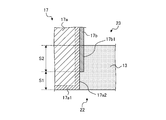
- FIG. 7 is an enlarged cross-sectional view showing the end current collecting member 17 according to the modified example 4 of the embodiment.
- the surface roughness Ra of the surface 17a2 of the natural oxide film 17a1 in contact with the fixing material 13 is larger than the surface roughness Ra of the surface 17b1 of the covering material 17b in contact with the fixing material 13. May be good.
- the end current collecting member 17 is on the reducing atmosphere side (that is, the internal space 22 side) where peeling is likely to occur. And the fixing force 13 can be improved.
- the base material 17a on the oxidizing atmosphere side that is, the external space 23 side
- Cr diffusion can be suppressed.
- the durability of the end current collecting member 17 can be increased, so that the durability of the cell stack device 10 can be increased.
- the area S1 of the surface 17a2 in contact with the fixing material 13 of the natural oxide film 17a1 may be smaller than the area S2 of the surface 17b1 in contact with the fixing material 13 of the covering material 17b.
- the end current collecting member 17 is peeled off from the fixing material 13 to fuel. It is possible to suppress the occurrence of gas leakage.
- the durability of the end current collecting member 17 can be increased, so that the durability of the cell stack device 10 can be increased.
- FIG. 8 is an enlarged cross-sectional view showing the end current collecting member 17 according to the modified example 5 of the embodiment.
- the covering material 17b is located on one end (lower end) 17b2 side of the covering material 17b, and connects the surface 17a2 of the natural oxide film 17a1 and the surface 17b1 of the covering material 17b. It may have a surface 17b3 to be formed.
- the surface 17b3 is, for example, a tapered surface that is inclined with respect to the surface 17b1 of the covering material 17b.
- the covering material 17b has the surface 17b3, the contact area between the covering material 17b and the fixing material 13 increases. As a result, the durability of the end current collecting member 17 can be increased, so that the durability of the cell stack device 10 can be increased.
- FIG. 9 is an enlarged cross-sectional view showing the end current collecting member 17 according to the modified example 6 of the embodiment.
- the covering material 17b is located on one end (lower end) 17b2 side of the covering material 17b, protrudes in the direction away from the end current collecting member 17, and faces the fixing material 13. It may have a protruding portion 17b4 to be formed.
- the covering material 17b has the protruding portion 17b4
- the contact area between the covering material 17b and the fixing material 13 increases.
- the durability of the end current collecting member 17 can be increased, so that the durability of the cell stack device 10 can be increased.
- the covering material 17b is shown as having a surface 17b3 or a protruding portion 17b4 in FIGS. 8 and 9, the covering material 17b may have a surface 17b3 and a protruding portion 17b4.
- FIG. 10 is a cross-sectional view showing the end current collecting member 17 according to the modified example 7 of the embodiment.
- the entire surface of the end current collecting member 17 is covered with the covering material 17b, and one end (lower end in the figure) of the end current collecting member 17 stays inside the fixing material 13, and the internal space from the fixing material 13 The case where it does not protrude to 22 is shown.
- the durability of the end current collecting member 17 can be increased, so that the durability of the cell stack device 10 can be increased.
- the end current collecting member 17 since it is not necessary to perform an etching process or the like after forming the covering material 17b on the entire surface of the base material 17a, the end current collecting member 17 can be manufactured at low cost.
- FIG. 11 is a cross-sectional view showing the end current collecting member 17 according to the modified example 8 of the embodiment.
- the surface of the end current collecting member 17 according to the modified example 8 in contact with the fixing material 13 is covered with a film different from that of the covering material 17b.
- the surface in contact with the fixing material 13 is covered with the natural oxide film 17a1 of the base material 17a.
- the durability of the end current collecting member 17 can be further enhanced, so that the durability of the cell stack device 10 can be further enhanced.
- FIG. 12 is a cross-sectional view showing the end current collecting member 17 according to the modified example 9 of the embodiment.
- the surface in contact with the fixing material 13 is covered with the natural oxide film 17a1, but the film covering the surface in contact with the fixing material 13 is not limited to the natural oxide film 17a1.
- the surface in contact with the fixing material 13 may be covered with the reduction prevention film 17c.
- the reduction prevention film 17c it is possible to prevent manganese, which is a constituent element of the coating material 17b, from diffusing into the fixing material 13 which is a glass material and causing cracks or the like in the coating material 17b during high-temperature operation.
- the durability of the end current collecting member 17 can be further enhanced, so that the durability of the cell stack device 10 can be further enhanced.
- FIG. 13 is an external perspective view showing the module 80 according to the embodiment, in which the front surface and the rear surface which are a part of the storage container 81 are removed, and the cell stack device 10 of the fuel cell stored inside is taken out rearward. Is shown.
- the module 80 includes a storage container 81 and a cell stack device 10 housed in the storage container 81.
- a reformer 82 is arranged above the cell stack device 10.
- the reformer 82 reforms raw fuels such as natural gas and kerosene to generate fuel gas, which is supplied to cell 1.
- the raw fuel is supplied to the reformer 82 through the raw fuel supply pipe 83.
- the reformer 82 may include a vaporizing unit 82a for vaporizing water and a reforming unit 82b.
- the reforming unit 82b is provided with a reforming catalyst (not shown), and reforms the raw material fuel into fuel gas.
- a reformer 82 can perform steam reforming, which is a highly efficient reforming reaction.
- the fuel gas generated by the reformer 82 is supplied to the gas flow path 2a (see FIG. 1A) of the cell 1 through the gas flow pipe 20, the gas tank 16, and the fixing member 12.
- the temperature inside the module 80 at the time of normal power generation becomes about 500 to 1000 ° C. due to the combustion of gas and the power generation of the cell 1.
- the module 80 having high durability can be obtained by accommodating and configuring the cell stack device 10 having high durability.
- FIG. 14 is an exploded perspective view showing an example of the module accommodating device 90 according to the embodiment.
- the module accommodating device 90 according to the embodiment includes an outer case 91, a module 80 shown in FIG. 13, and an auxiliary machine (not shown).
- the auxiliary device operates the module 80.
- the module 80 and auxiliary equipment are housed in the outer case 91. In FIG. 14, a part of the configuration is omitted.
- the exterior case 91 of the module accommodating device 90 shown in FIG. 14 has a support column 92 and an exterior plate 93.
- the partition plate 94 divides the inside of the outer case 91 into upper and lower parts.
- the space above the partition plate 94 in the outer case 91 is a module storage chamber 95 for accommodating the module 80, and the space below the partition plate 94 in the exterior case 91 accommodates an auxiliary machine for operating the module 80.
- Auxiliary equipment storage room 96 In addition, in FIG. 14, the auxiliary machine accommodated in the auxiliary machine accommodating chamber 96 is omitted.
- the partition plate 94 has an air flow port 97 for flowing the air of the auxiliary machine accommodating chamber 96 to the module accommodating chamber 95 side.
- the exterior plate 93 constituting the module accommodating chamber 95 has an exhaust port 98 for exhausting the air in the module accommodating chamber 95.
- module accommodating device 90 As described above, by providing the module accommodating chamber 95 with a highly durable module 80, the module accommodating device 90 having high durability can be obtained.
- a vertical stripe type cell stack device in which so-called “vertical stripe type” cells in which only one power generation element portion consisting of a fuel electrode, a solid electrolyte layer and an air electrode is provided on the surface of a support substrate is arranged is exemplified.
- the present disclosure is a horizontal stripe type in which so-called “horizontal stripe type” cells in which power generation element portions are provided at a plurality of locations on the surface of a support substrate and are electrically connected between adjacent power generation element portions are arranged. It can be applied to cell stack devices.
- a case where a hollow flat plate type support substrate is used is illustrated.
- the present disclosure can also be applied to a cell stack device using a cylindrical support substrate.
- the present disclosure can also be applied to a flat plate type cell stack device in which so-called "flat plate type” cells are arranged in the thickness direction.
- a fuel electrode is provided on a support substrate and an air electrode is arranged on the surface of a cell.
- the present disclosure can also be applied to a cell stacking device in which the air electrode is provided on the support substrate and the fuel electrode is arranged on the surface of the cell in the opposite arrangement.
- the fuel cell, the fuel cell stack device, the fuel cell module, and the fuel cell device are shown as examples of the “cell”, the “cell stack device”, the “module”, and the “module accommodating device”.
- Other examples may be an electrolytic cell, an electrolytic cell stacking device, an electrolytic module and an electrolytic device, respectively.
- the cell stack device 10 includes the cell stack 11 and the end current collecting member 17.
- a plurality of cells 1 are arranged in the cell stack 11.
- the end current collecting member 17 is located at the end of the cell stack 11 in the arrangement direction of the plurality of cells 1.
- the surface of the end current collecting member 17 exposed to the oxidizing atmosphere is covered with the covering material 17b containing manganese, and the surface of the end current collecting member 17 exposed to the reducing atmosphere (internal space 22).
- it is covered with a film different from that of the covering material 17b. Thereby, the durability of the cell stack device 10 can be improved.
- the cell stack device 10 further includes a fixing member 13 for fixing the cell 1 and the end current collecting member 17. Then, the surface of the end current collecting member 17 in contact with the fixing material 13 is covered with a film different from that of the covering material 17b. Thereby, the durability of the cell stack device 10 can be further improved.
- the cell stack device 10 further includes a fixing member 13 for fixing the cell 1 and the end current collecting member 17.
- a film different from the covering material 17b and the covering material is located on the surface of the end current collecting member 17 in contact with the fixing material 13. Thereby, the durability of the cell stack device 10 can be improved.
- the surface roughness of the film different from the covering material 17b located on the surface of the end current collecting member 17 in contact with the fixing material 13 is different from that of the fixing material 17 in the end current collecting member 17. It is larger than the surface roughness of the covering material 17b located on the surface in contact with 13. Thereby, the durability of the cell stack device 10 can be improved.
- the area S1 of the film different from the covering material 17b located on the surface of the end current collecting member 17 in contact with the fixing material 13 is the fixing material 13 in the end current collecting member 17. It is smaller than the area S2 of the covering material 17b located on the surface in contact with. Thereby, the durability of the cell stack device 10 can be improved.
- the end current collecting member 17 is made of stainless steel, and the film different from the covering material 17b is a natural oxide film 17a1 located on the surface of stainless steel. As a result, the durability of the cell stack device 10 can be improved, and the end current collecting member 17 can be manufactured at low cost.
- the film different from the coating material 17b is the reduction prevention film 17c.
- the durability of the cell stack device 10 can be improved, and the performance of the end current collecting member 17 can be improved.
- the cell stack device 10 includes a cell stack 11 and an end current collecting member 17.
- a plurality of cells 1 are arranged in the cell stack 11.
- the end current collecting member 17 is located at the end of the cell stack 11 in the arrangement direction of the plurality of cells 1.
- the end current collecting member 17 is not exposed to the reducing atmosphere (internal space 22). Thereby, the durability of the cell stack device 10 can be improved.
- the entire surface of the end current collecting member 17 is covered with a covering material 17b containing manganese.
- a covering material 17b containing manganese As a result, the durability of the cell stack device 10 can be improved, and the end current collecting member 17 can be manufactured at low cost.
- the cell stack device 10 further includes a fixing member 13 for fixing the cell 1 and the end current collecting member 17. Then, the surface of the end current collector member 17 exposed to the oxidizing atmosphere (external space 23) is covered with the covering material 17b containing manganese, and the surface of the end current collecting member 17 in contact with the fixing material 13 is the covering material 17b. Covered with a different film. Thereby, the durability of the cell stack device 10 can be further improved.
- the module 80 according to the embodiment is configured by accommodating the cell stack device 10 described above in the storage container 81. As a result, the module 80 has high durability.
- the module accommodating device 90 is configured by accommodating the module 80 described above and an auxiliary machine for operating the module 80 in the outer case 91. By this.
- the module accommodating device 90 with high durability can be used.
- the metal member (end current collecting member 17) has a surface exposed to an oxidizing atmosphere (external space 23) and a surface exposed to a reducing atmosphere (internal space 22). Then, the surface exposed to the oxidizing atmosphere (external space 23) is covered with the covering material 17b containing manganese, and the surface exposed to the reducing atmosphere (internal space 22) is covered with a film different from the covering material 17b. Thereby, the durability of the end current collecting member 17 can be enhanced.
Landscapes
- Chemical & Material Sciences (AREA)
- Engineering & Computer Science (AREA)
- Life Sciences & Earth Sciences (AREA)
- Manufacturing & Machinery (AREA)
- Sustainable Development (AREA)
- Sustainable Energy (AREA)
- Chemical Kinetics & Catalysis (AREA)
- Electrochemistry (AREA)
- General Chemical & Material Sciences (AREA)
- Composite Materials (AREA)
- Ceramic Engineering (AREA)
- Fuel Cell (AREA)
Priority Applications (4)
| Application Number | Priority Date | Filing Date | Title |
|---|---|---|---|
| EP20892230.2A EP4068436A4 (en) | 2019-11-29 | 2020-10-08 | CELL STACKING DEVICE, MODULE, MODULE HOUSING DEVICE AND METAL ELEMENT |
| JP2021504484A JP6960556B1 (ja) | 2019-11-29 | 2020-10-08 | セルスタック装置、モジュール、モジュール収容装置および金属部材 |
| CN202080077366.2A CN114651353B (zh) | 2019-11-29 | 2020-10-08 | 单电池堆装置、模块、模块收容装置以及金属构件 |
| US17/774,744 US12212023B2 (en) | 2019-11-29 | 2020-10-08 | Cell stack device, module, module housing device, and metal member |
Applications Claiming Priority (2)
| Application Number | Priority Date | Filing Date | Title |
|---|---|---|---|
| JP2019-216805 | 2019-11-29 | ||
| JP2019216805 | 2019-11-29 |
Publications (1)
| Publication Number | Publication Date |
|---|---|
| WO2021106384A1 true WO2021106384A1 (ja) | 2021-06-03 |
Family
ID=76129536
Family Applications (1)
| Application Number | Title | Priority Date | Filing Date |
|---|---|---|---|
| PCT/JP2020/038213 Ceased WO2021106384A1 (ja) | 2019-11-29 | 2020-10-08 | セルスタック装置、モジュール、モジュール収容装置および金属部材 |
Country Status (5)
| Country | Link |
|---|---|
| US (1) | US12212023B2 (https=) |
| EP (1) | EP4068436A4 (https=) |
| JP (2) | JP6960556B1 (https=) |
| CN (1) | CN114651353B (https=) |
| WO (1) | WO2021106384A1 (https=) |
Cited By (1)
| Publication number | Priority date | Publication date | Assignee | Title |
|---|---|---|---|---|
| JPWO2023176979A1 (https=) * | 2022-03-18 | 2023-09-21 |
Citations (4)
| Publication number | Priority date | Publication date | Assignee | Title |
|---|---|---|---|---|
| WO2007049759A1 (ja) * | 2005-10-27 | 2007-05-03 | Kyocera Corporation | 耐熱性合金部材、燃料電池用合金部材、燃料電池用集電部材、セルスタック、及び燃料電池 |
| JP2007149618A (ja) * | 2005-11-30 | 2007-06-14 | Kyocera Corp | 燃料電池セルスタックにおける集電構造 |
| JP2011181291A (ja) * | 2010-02-26 | 2011-09-15 | Mitsubishi Heavy Ind Ltd | 固体電解質型燃料電池 |
| JP2015162357A (ja) | 2014-02-27 | 2015-09-07 | 京セラ株式会社 | セルスタック装置、燃料電池モジュールおよび燃料電池装置 |
Family Cites Families (19)
| Publication number | Priority date | Publication date | Assignee | Title |
|---|---|---|---|---|
| AUPN173595A0 (en) * | 1995-03-15 | 1995-04-06 | Ceramic Fuel Cells Limited | Fuel cell interconnect device |
| JP2000182645A (ja) | 1998-12-15 | 2000-06-30 | Kansai Electric Power Co Inc:The | 固体電解質型燃料電池モジュール |
| JP2001196077A (ja) | 2000-01-13 | 2001-07-19 | Tokyo Gas Co Ltd | 固体電解質型燃料電池のセパレータ |
| JP2003346843A (ja) | 2002-05-29 | 2003-12-05 | Sanyo Electric Co Ltd | 円筒形固体酸化物燃料電池およびその運転方法 |
| JP5300199B2 (ja) | 2007-01-29 | 2013-09-25 | 京セラ株式会社 | 燃料電池 |
| JP5230812B2 (ja) | 2010-02-25 | 2013-07-10 | 京セラ株式会社 | 複合体、集電部材、ガスタンクおよび燃料電池セル装置 |
| JP4942854B2 (ja) | 2011-11-02 | 2012-05-30 | 京セラ株式会社 | 燃料電池セルスタックにおける集電構造 |
| TWI552417B (zh) | 2011-11-17 | 2016-10-01 | 博隆能源股份有限公司 | 對氧化鋯為主之電解質提供抗腐蝕性之多層塗層 |
| KR101421504B1 (ko) * | 2012-03-29 | 2014-07-22 | 서울대학교산학협력단 | 플렉서블 연료전지 및 그 제조방법 |
| DE202013012748U1 (de) * | 2012-05-17 | 2019-02-04 | Kyocera Corporation | Elektrisch leitfähiges Element, Zellenstapel, elektrochemisches Modul und elektrochemische Vorrichtung |
| CN106233519B (zh) * | 2014-04-21 | 2019-04-05 | 京瓷株式会社 | 电池堆装置、模块以及模块收容装置 |
| GB2524643B (en) | 2015-02-10 | 2017-03-29 | Ceres Ip Co Ltd | Interconnect for Low Temperature Solid Oxide Fuel Cell |
| CN107431215B (zh) | 2015-03-26 | 2020-10-16 | 森村索福克科技股份有限公司 | 电化学反应单元和燃料电池堆 |
| EP3331077B1 (en) * | 2015-07-29 | 2020-02-12 | Kyocera Corporation | Cell stack device, module, and module housing device |
| WO2017069033A1 (ja) | 2015-10-23 | 2017-04-27 | 日本特殊陶業株式会社 | インターコネクタ-電気化学反応単セル複合体、および、電気化学反応セルスタック |
| JP2017152096A (ja) | 2016-02-22 | 2017-08-31 | Toto株式会社 | 燃料電池セルスタック、及び、固体酸化物形燃料電池装置 |
| JP6835572B2 (ja) * | 2016-12-26 | 2021-02-24 | 京セラ株式会社 | セルスタック装置、モジュールおよびモジュール収容装置 |
| JP6359169B2 (ja) * | 2017-01-12 | 2018-07-18 | 日本碍子株式会社 | 燃料電池スタック |
| JP6637939B2 (ja) * | 2017-10-12 | 2020-01-29 | 日本碍子株式会社 | 燃料電池セル及びセルスタック装置 |
-
2020
- 2020-10-08 CN CN202080077366.2A patent/CN114651353B/zh active Active
- 2020-10-08 EP EP20892230.2A patent/EP4068436A4/en active Pending
- 2020-10-08 JP JP2021504484A patent/JP6960556B1/ja active Active
- 2020-10-08 WO PCT/JP2020/038213 patent/WO2021106384A1/ja not_active Ceased
- 2020-10-08 US US17/774,744 patent/US12212023B2/en active Active
-
2021
- 2021-10-11 JP JP2021166852A patent/JP7685413B2/ja active Active
Patent Citations (4)
| Publication number | Priority date | Publication date | Assignee | Title |
|---|---|---|---|---|
| WO2007049759A1 (ja) * | 2005-10-27 | 2007-05-03 | Kyocera Corporation | 耐熱性合金部材、燃料電池用合金部材、燃料電池用集電部材、セルスタック、及び燃料電池 |
| JP2007149618A (ja) * | 2005-11-30 | 2007-06-14 | Kyocera Corp | 燃料電池セルスタックにおける集電構造 |
| JP2011181291A (ja) * | 2010-02-26 | 2011-09-15 | Mitsubishi Heavy Ind Ltd | 固体電解質型燃料電池 |
| JP2015162357A (ja) | 2014-02-27 | 2015-09-07 | 京セラ株式会社 | セルスタック装置、燃料電池モジュールおよび燃料電池装置 |
Non-Patent Citations (1)
| Title |
|---|
| See also references of EP4068436A4 |
Cited By (2)
| Publication number | Priority date | Publication date | Assignee | Title |
|---|---|---|---|---|
| JPWO2023176979A1 (https=) * | 2022-03-18 | 2023-09-21 | ||
| WO2023176979A1 (ja) * | 2022-03-18 | 2023-09-21 | 京セラ株式会社 | 電気化学セル、電気化学セル装置、モジュールおよびモジュール収容装置 |
Also Published As
| Publication number | Publication date |
|---|---|
| JPWO2021106384A1 (https=) | 2021-06-03 |
| JP2022000870A (ja) | 2022-01-04 |
| CN114651353B (zh) | 2024-12-24 |
| JP7685413B2 (ja) | 2025-05-29 |
| EP4068436A4 (en) | 2025-07-09 |
| CN114651353A (zh) | 2022-06-21 |
| US12212023B2 (en) | 2025-01-28 |
| JP6960556B1 (ja) | 2021-11-05 |
| US20220376271A1 (en) | 2022-11-24 |
| EP4068436A1 (en) | 2022-10-05 |
Similar Documents
| Publication | Publication Date | Title |
|---|---|---|
| WO2021221052A1 (ja) | セル、セルスタック装置、モジュールおよびモジュール収容装置 | |
| WO2021205734A1 (ja) | セル、モジュールおよびモジュール収容装置 | |
| JP7027621B1 (ja) | セル、セルスタック装置、モジュールおよびモジュール収容装置 | |
| JP7672999B2 (ja) | 電気化学セル、電気化学セル装置、モジュールおよびモジュール収容装置 | |
| JP2023139044A (ja) | 電気化学セル装置、モジュールおよびモジュール収容装置 | |
| JP6960556B1 (ja) | セルスタック装置、モジュール、モジュール収容装置および金属部材 | |
| JP7692059B2 (ja) | 電気化学セル装置、モジュールおよびモジュール収容装置 | |
| US20230327162A1 (en) | Cell, cell stack device, module, and module housing device | |
| JP6942273B2 (ja) | セルスタック装置、モジュールおよびモジュール収容装置 | |
| WO2021221071A1 (ja) | セル、セルスタック装置、モジュールおよびモジュール収容装置 | |
| WO2021172481A1 (ja) | セルスタック装置、モジュール、モジュール収容装置および導電部材 | |
| JP7657386B1 (ja) | 固体電解質層、電気化学セル、電気化学セル装置、モジュールおよびモジュール収容装置 | |
| JP7664714B2 (ja) | セル、セルスタック装置、モジュールおよびモジュール収容装置 | |
| JP7583227B2 (ja) | 電気化学セル、電気化学セル装置、モジュールおよびモジュール収容装置 | |
| JP2024048859A (ja) | 電気化学セル装置、モジュールおよびモジュール収容装置 | |
| WO2024143416A1 (ja) | 導電部材、電気化学セル装置、モジュールおよびモジュール収容装置 | |
| WO2024143355A1 (ja) | 電気化学セル、電気化学セル装置、モジュールおよびモジュール収容装置 | |
| WO2024143512A1 (ja) | 電気化学セル、電気化学セル装置、モジュールおよびモジュール収容装置 | |
| JP2025021234A (ja) | 電気化学セル、電気化学セル装置、モジュールおよびモジュール収容装置 | |
| WO2025070717A1 (ja) | 電気化学セル、電気化学セル装置、モジュールおよびモジュール収容装置 | |
| WO2024150829A1 (ja) | 電気化学セル、電気化学セル装置、モジュールおよびモジュール収容装置 | |
| WO2024117052A1 (ja) | 複合部材、電気化学セル、電気化学セル装置、モジュールおよびモジュール収容装置 | |
| WO2024247989A1 (ja) | 電気化学セル、電気化学セル装置、モジュールおよびモジュール収容装置 |
Legal Events
| Date | Code | Title | Description |
|---|---|---|---|
| ENP | Entry into the national phase |
Ref document number: 2021504484 Country of ref document: JP Kind code of ref document: A |
|
| 121 | Ep: the epo has been informed by wipo that ep was designated in this application |
Ref document number: 20892230 Country of ref document: EP Kind code of ref document: A1 |
|
| NENP | Non-entry into the national phase |
Ref country code: DE |
|
| ENP | Entry into the national phase |
Ref document number: 2020892230 Country of ref document: EP Effective date: 20220629 |