WO2021100784A1 - 発熱装置、熱利用システムおよびフィルム状発熱体 - Google Patents
発熱装置、熱利用システムおよびフィルム状発熱体 Download PDFInfo
- Publication number
- WO2021100784A1 WO2021100784A1 PCT/JP2020/043076 JP2020043076W WO2021100784A1 WO 2021100784 A1 WO2021100784 A1 WO 2021100784A1 JP 2020043076 W JP2020043076 W JP 2020043076W WO 2021100784 A1 WO2021100784 A1 WO 2021100784A1
- Authority
- WO
- WIPO (PCT)
- Prior art keywords
- layer
- heating element
- fluid
- film
- heat
- Prior art date
- Legal status (The legal status is an assumption and is not a legal conclusion. Google has not performed a legal analysis and makes no representation as to the accuracy of the status listed.)
- Ceased
Links
Images











Classifications
-
- C—CHEMISTRY; METALLURGY
- C09—DYES; PAINTS; POLISHES; NATURAL RESINS; ADHESIVES; COMPOSITIONS NOT OTHERWISE PROVIDED FOR; APPLICATIONS OF MATERIALS NOT OTHERWISE PROVIDED FOR
- C09K—MATERIALS FOR MISCELLANEOUS APPLICATIONS, NOT PROVIDED FOR ELSEWHERE
- C09K5/00—Heat-transfer, heat-exchange or heat-storage materials, e.g. refrigerants; Materials for the production of heat or cold by chemical reactions other than by combustion
- C09K5/16—Materials undergoing chemical reactions when used
-
- F—MECHANICAL ENGINEERING; LIGHTING; HEATING; WEAPONS; BLASTING
- F24—HEATING; RANGES; VENTILATING
- F24V—COLLECTION, PRODUCTION OR USE OF HEAT NOT OTHERWISE PROVIDED FOR
- F24V30/00—Apparatus or devices using heat produced by exothermal chemical reactions other than combustion
-
- C—CHEMISTRY; METALLURGY
- C01—INORGANIC CHEMISTRY
- C01B—NON-METALLIC ELEMENTS; COMPOUNDS THEREOF; METALLOIDS OR COMPOUNDS THEREOF NOT COVERED BY SUBCLASS C01C
- C01B3/00—Hydrogen; Gaseous mixtures containing hydrogen; Separation of hydrogen from mixtures containing it; Purification of hydrogen; Reversible storage of hydrogen
- C01B3/0005—Reversible storage of hydrogen, e.g. by hydrogen getters or electrodes
- C01B3/001—Reversible storage of hydrogen, e.g. by hydrogen getters or electrodes characterised by the uptaking media; Treatment thereof
-
- C—CHEMISTRY; METALLURGY
- C01—INORGANIC CHEMISTRY
- C01B—NON-METALLIC ELEMENTS; COMPOUNDS THEREOF; METALLOIDS OR COMPOUNDS THEREOF NOT COVERED BY SUBCLASS C01C
- C01B3/00—Hydrogen; Gaseous mixtures containing hydrogen; Separation of hydrogen from mixtures containing it; Purification of hydrogen; Reversible storage of hydrogen
- C01B3/0005—Reversible storage of hydrogen, e.g. by hydrogen getters or electrodes
- C01B3/001—Reversible storage of hydrogen, e.g. by hydrogen getters or electrodes characterised by the uptaking media; Treatment thereof
- C01B3/0018—Inorganic elements or compounds, e.g. oxides, nitrides, borohydrides or zeolites; Solutions thereof
- C01B3/0026—Metals or metal hydrides
-
- C—CHEMISTRY; METALLURGY
- C01—INORGANIC CHEMISTRY
- C01B—NON-METALLIC ELEMENTS; COMPOUNDS THEREOF; METALLOIDS OR COMPOUNDS THEREOF NOT COVERED BY SUBCLASS C01C
- C01B3/00—Hydrogen; Gaseous mixtures containing hydrogen; Separation of hydrogen from mixtures containing it; Purification of hydrogen; Reversible storage of hydrogen
- C01B3/0005—Reversible storage of hydrogen, e.g. by hydrogen getters or electrodes
- C01B3/001—Reversible storage of hydrogen, e.g. by hydrogen getters or electrodes characterised by the uptaking media; Treatment thereof
- C01B3/0018—Inorganic elements or compounds, e.g. oxides, nitrides, borohydrides or zeolites; Solutions thereof
- C01B3/0031—Intermetallic compounds; Metal alloys
-
- C—CHEMISTRY; METALLURGY
- C01—INORGANIC CHEMISTRY
- C01B—NON-METALLIC ELEMENTS; COMPOUNDS THEREOF; METALLOIDS OR COMPOUNDS THEREOF NOT COVERED BY SUBCLASS C01C
- C01B3/00—Hydrogen; Gaseous mixtures containing hydrogen; Separation of hydrogen from mixtures containing it; Purification of hydrogen; Reversible storage of hydrogen
- C01B3/0005—Reversible storage of hydrogen, e.g. by hydrogen getters or electrodes
- C01B3/001—Reversible storage of hydrogen, e.g. by hydrogen getters or electrodes characterised by the uptaking media; Treatment thereof
- C01B3/0018—Inorganic elements or compounds, e.g. oxides, nitrides, borohydrides or zeolites; Solutions thereof
- C01B3/0031—Intermetallic compounds; Metal alloys
- C01B3/0036—Intermetallic compounds; Metal alloys only containing iron and titanium
-
- C—CHEMISTRY; METALLURGY
- C01—INORGANIC CHEMISTRY
- C01B—NON-METALLIC ELEMENTS; COMPOUNDS THEREOF; METALLOIDS OR COMPOUNDS THEREOF NOT COVERED BY SUBCLASS C01C
- C01B3/00—Hydrogen; Gaseous mixtures containing hydrogen; Separation of hydrogen from mixtures containing it; Purification of hydrogen; Reversible storage of hydrogen
- C01B3/0005—Reversible storage of hydrogen, e.g. by hydrogen getters or electrodes
- C01B3/001—Reversible storage of hydrogen, e.g. by hydrogen getters or electrodes characterised by the uptaking media; Treatment thereof
- C01B3/0018—Inorganic elements or compounds, e.g. oxides, nitrides, borohydrides or zeolites; Solutions thereof
- C01B3/0031—Intermetallic compounds; Metal alloys
- C01B3/0042—Intermetallic compounds; Metal alloys only containing magnesium and nickel
-
- C—CHEMISTRY; METALLURGY
- C01—INORGANIC CHEMISTRY
- C01B—NON-METALLIC ELEMENTS; COMPOUNDS THEREOF; METALLOIDS OR COMPOUNDS THEREOF NOT COVERED BY SUBCLASS C01C
- C01B3/00—Hydrogen; Gaseous mixtures containing hydrogen; Separation of hydrogen from mixtures containing it; Purification of hydrogen; Reversible storage of hydrogen
- C01B3/0005—Reversible storage of hydrogen, e.g. by hydrogen getters or electrodes
- C01B3/001—Reversible storage of hydrogen, e.g. by hydrogen getters or electrodes characterised by the uptaking media; Treatment thereof
- C01B3/0018—Inorganic elements or compounds, e.g. oxides, nitrides, borohydrides or zeolites; Solutions thereof
- C01B3/0031—Intermetallic compounds; Metal alloys
- C01B3/0047—Intermetallic compounds; Metal alloys containing a rare earth metal
-
- C—CHEMISTRY; METALLURGY
- C01—INORGANIC CHEMISTRY
- C01B—NON-METALLIC ELEMENTS; COMPOUNDS THEREOF; METALLOIDS OR COMPOUNDS THEREOF NOT COVERED BY SUBCLASS C01C
- C01B3/00—Hydrogen; Gaseous mixtures containing hydrogen; Separation of hydrogen from mixtures containing it; Purification of hydrogen; Reversible storage of hydrogen
- C01B3/0005—Reversible storage of hydrogen, e.g. by hydrogen getters or electrodes
- C01B3/001—Reversible storage of hydrogen, e.g. by hydrogen getters or electrodes characterised by the uptaking media; Treatment thereof
- C01B3/0084—Solid storage media characterised by their shape, e.g. porous compacts or hollow particles
-
- F—MECHANICAL ENGINEERING; LIGHTING; HEATING; WEAPONS; BLASTING
- F17—STORING OR DISTRIBUTING GASES OR LIQUIDS
- F17C—VESSELS FOR CONTAINING OR STORING COMPRESSED, LIQUEFIED OR SOLIDIFIED GASES; FIXED-CAPACITY GAS-HOLDERS; FILLING VESSELS WITH, OR DISCHARGING FROM VESSELS, COMPRESSED, LIQUEFIED, OR SOLIDIFIED GASES
- F17C11/00—Use of gas-solvents or gas-sorbents in vessels
- F17C11/005—Use of gas-solvents or gas-sorbents in vessels for hydrogen
-
- F—MECHANICAL ENGINEERING; LIGHTING; HEATING; WEAPONS; BLASTING
- F22—STEAM GENERATION
- F22B—METHODS OF STEAM GENERATION; STEAM BOILERS
- F22B3/00—Other methods of steam generation; Steam boilers not provided for in other groups of this subclass
-
- F—MECHANICAL ENGINEERING; LIGHTING; HEATING; WEAPONS; BLASTING
- F22—STEAM GENERATION
- F22D—PREHEATING, OR ACCUMULATING PREHEATED, FEED-WATER FOR STEAM GENERATION; FEED-WATER SUPPLY FOR STEAM GENERATION; CONTROLLING WATER LEVEL FOR STEAM GENERATION; AUXILIARY DEVICES FOR PROMOTING WATER CIRCULATION WITHIN STEAM BOILERS
- F22D1/00—Feed-water heaters, i.e. economisers or like preheaters
-
- F—MECHANICAL ENGINEERING; LIGHTING; HEATING; WEAPONS; BLASTING
- F28—HEAT EXCHANGE IN GENERAL
- F28D—HEAT-EXCHANGE APPARATUS, NOT PROVIDED FOR IN ANOTHER SUBCLASS, IN WHICH THE HEAT-EXCHANGE MEDIA DO NOT COME INTO DIRECT CONTACT
- F28D1/00—Heat-exchange apparatus having stationary conduit assemblies for one heat-exchange medium only, the media being in contact with different sides of the conduit wall, in which the other heat-exchange medium is a large body of fluid, e.g. domestic or motor car radiators
- F28D1/06—Heat-exchange apparatus having stationary conduit assemblies for one heat-exchange medium only, the media being in contact with different sides of the conduit wall, in which the other heat-exchange medium is a large body of fluid, e.g. domestic or motor car radiators with the heat-exchange conduits forming part of, or being attached to, the tank containing the body of fluid
-
- F—MECHANICAL ENGINEERING; LIGHTING; HEATING; WEAPONS; BLASTING
- F28—HEAT EXCHANGE IN GENERAL
- F28D—HEAT-EXCHANGE APPARATUS, NOT PROVIDED FOR IN ANOTHER SUBCLASS, IN WHICH THE HEAT-EXCHANGE MEDIA DO NOT COME INTO DIRECT CONTACT
- F28D20/00—Heat storage plants or apparatus in general; Regenerative heat-exchange apparatus not covered by groups F28D17/00 or F28D19/00
- F28D20/003—Heat storage plants or apparatus in general; Regenerative heat-exchange apparatus not covered by groups F28D17/00 or F28D19/00 using thermochemical reactions
-
- F—MECHANICAL ENGINEERING; LIGHTING; HEATING; WEAPONS; BLASTING
- F28—HEAT EXCHANGE IN GENERAL
- F28D—HEAT-EXCHANGE APPARATUS, NOT PROVIDED FOR IN ANOTHER SUBCLASS, IN WHICH THE HEAT-EXCHANGE MEDIA DO NOT COME INTO DIRECT CONTACT
- F28D7/00—Heat-exchange apparatus having stationary tubular conduit assemblies for both heat-exchange media, the media being in contact with different sides of a conduit wall
- F28D7/16—Heat-exchange apparatus having stationary tubular conduit assemblies for both heat-exchange media, the media being in contact with different sides of a conduit wall the conduits being arranged in parallel spaced relation
-
- C—CHEMISTRY; METALLURGY
- C01—INORGANIC CHEMISTRY
- C01B—NON-METALLIC ELEMENTS; COMPOUNDS THEREOF; METALLOIDS OR COMPOUNDS THEREOF NOT COVERED BY SUBCLASS C01C
- C01B2203/00—Integrated processes for the production of hydrogen or synthesis gas
- C01B2203/04—Integrated processes for the production of hydrogen or synthesis gas containing a purification step for the hydrogen or the synthesis gas
- C01B2203/0405—Purification by membrane separation
-
- F—MECHANICAL ENGINEERING; LIGHTING; HEATING; WEAPONS; BLASTING
- F28—HEAT EXCHANGE IN GENERAL
- F28F—DETAILS OF HEAT-EXCHANGE AND HEAT-TRANSFER APPARATUS, OF GENERAL APPLICATION
- F28F2250/00—Arrangements for modifying the flow of the heat exchange media, e.g. flow guiding means; Particular flow patterns
- F28F2250/06—Derivation channels, e.g. bypass
-
- G—PHYSICS
- G21—NUCLEAR PHYSICS; NUCLEAR ENGINEERING
- G21B—FUSION REACTORS
- G21B3/00—Low temperature nuclear fusion reactors, e.g. alleged cold fusion reactors
- G21B3/002—Fusion by absorption in a matrix
-
- Y—GENERAL TAGGING OF NEW TECHNOLOGICAL DEVELOPMENTS; GENERAL TAGGING OF CROSS-SECTIONAL TECHNOLOGIES SPANNING OVER SEVERAL SECTIONS OF THE IPC; TECHNICAL SUBJECTS COVERED BY FORMER USPC CROSS-REFERENCE ART COLLECTIONS [XRACs] AND DIGESTS
- Y02—TECHNOLOGIES OR APPLICATIONS FOR MITIGATION OR ADAPTATION AGAINST CLIMATE CHANGE
- Y02E—REDUCTION OF GREENHOUSE GAS [GHG] EMISSIONS, RELATED TO ENERGY GENERATION, TRANSMISSION OR DISTRIBUTION
- Y02E60/00—Enabling technologies; Technologies with a potential or indirect contribution to GHG emissions mitigation
- Y02E60/14—Thermal energy storage
-
- Y—GENERAL TAGGING OF NEW TECHNOLOGICAL DEVELOPMENTS; GENERAL TAGGING OF CROSS-SECTIONAL TECHNOLOGIES SPANNING OVER SEVERAL SECTIONS OF THE IPC; TECHNICAL SUBJECTS COVERED BY FORMER USPC CROSS-REFERENCE ART COLLECTIONS [XRACs] AND DIGESTS
- Y02—TECHNOLOGIES OR APPLICATIONS FOR MITIGATION OR ADAPTATION AGAINST CLIMATE CHANGE
- Y02E—REDUCTION OF GREENHOUSE GAS [GHG] EMISSIONS, RELATED TO ENERGY GENERATION, TRANSMISSION OR DISTRIBUTION
- Y02E60/00—Enabling technologies; Technologies with a potential or indirect contribution to GHG emissions mitigation
- Y02E60/30—Hydrogen technology
- Y02E60/32—Hydrogen storage
-
- Y—GENERAL TAGGING OF NEW TECHNOLOGICAL DEVELOPMENTS; GENERAL TAGGING OF CROSS-SECTIONAL TECHNOLOGIES SPANNING OVER SEVERAL SECTIONS OF THE IPC; TECHNICAL SUBJECTS COVERED BY FORMER USPC CROSS-REFERENCE ART COLLECTIONS [XRACs] AND DIGESTS
- Y02—TECHNOLOGIES OR APPLICATIONS FOR MITIGATION OR ADAPTATION AGAINST CLIMATE CHANGE
- Y02E—REDUCTION OF GREENHOUSE GAS [GHG] EMISSIONS, RELATED TO ENERGY GENERATION, TRANSMISSION OR DISTRIBUTION
- Y02E70/00—Other energy conversion or management systems reducing GHG emissions
- Y02E70/30—Systems combining energy storage with energy generation of non-fossil origin
Definitions
- Non-Patent Document 1 Since hydrogen can be generated from water, it is inexhaustible and inexpensive as a resource, and it does not generate greenhouse gases such as carbon dioxide, so it is regarded as clean energy. Further, the exothermic phenomenon using a hydrogen storage metal or the like is considered safe because there is no chain reaction unlike the fission reaction.
- the heat generated by the storage and release of hydrogen can be used as it is as heat, or it can be converted into electric power and used, so it is expected to be an effective energy source.
- the film-like heating element of the present invention has a film-like pedestal formed of a hydrogen storage metal, a hydrogen storage alloy, or a proton conductor, and a film-like multilayer film provided on the pedestal. Is formed of a first layer formed of a hydrogen storage metal or a hydrogen storage alloy and having a thickness of less than 1000 nm, and a hydrogen storage metal, a hydrogen storage alloy, or ceramics different from the first layer and having a thickness of less than 1000 nm. It has a second layer.
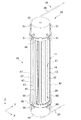
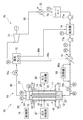
- the heating device 10 includes a closed container 11, a tubular body 12, a heating element 13, a flow path 14, a fluid circulation unit 15, and a control unit 16.
- a heating element 13 is provided outside the cylinder 12, and a flow path 14 is provided inside the cylinder 12, and the fluid flowing through the flow path 14 is heated by the heating element 13 to generate a high temperature. Generate a fluid.
- the closed container 11 has a main body 17 formed in a tubular shape, a fluid inflow chamber 18 provided at one end of the main body 17, and a fluid outflow chamber 19 provided at the other end of the main body 17.
- the side where the fluid inflow chamber 18 is provided with respect to the main body 17 is the lower side, and the side where the fluid outflow chamber 19 is provided with respect to the main body 17 is the upper side.
- the hollow portion 26 is connected to the gas discharge portion 28 via the gas outlet 22.
- the gas discharge portion 28 is composed of a vacuum pump, a pipe connecting the vacuum pump and the hollow portion 26, a valve for adjusting the flow rate of hydrogen-based gas and the pressure in the pipe, and the like. Perform vacuum exhaust.
- the tubular body 12 can have a cylindrical shape having a length of 10 m, a thickness (wall thickness) of 0.005 to 0.010 m, and a diameter of 0.05 m.
- the thickness is preferably appropriately designed based on the temperature and pressure of the fluid flowing through the inside of the tubular body 12 (flow path 14 described later).
- the tubular body 12 can be formed to a desired length, for example, by connecting a plurality of pipe materials in series.
- the number of cylinders 12 is not particularly limited, and may be one or more.
- 800 cylinders 12 can be installed in the closed container 11.
- a plurality of tubular bodies 12 are provided in the hollow portion 26. That is, the heat generating device 10 includes a plurality of tubular bodies 12 provided in the hollow portion 26. In FIG. 1, only one of the plurality of cylinders 12 is shown for simplification of the drawing, and the other cylinders 12 are omitted.
- the heating element 13 When the heated fluid flows into the flow path 14, the heating element 13 is heated via the tubular body 12. As a result, the heating element 13 generates excess heat, and the fluid flowing through the flow path 14 is heated via the tubular body 12. As a result, a high-temperature and high-pressure fluid is generated in the flow path 14, and the high-temperature and high-pressure fluid flows out of the flow path 14.
- the water flowing into the flow path 14 is heated by the heating element 13 that generates excess heat, and flows out from the flow path 14 as, for example, high temperature and high pressure water at 300 ° C. In some cases, a part of the water in the flow path 14 becomes water vapor.
- the circulation line 30 is provided with a cooling unit 32 for cooling the fluid and a heating unit 33 for heating the fluid. That is, the heat generating device 10 further includes a cooling unit 32 and a heating unit 33.
- a reservoir tank 36 for storing water and a pump 40 for circulating water are provided in the circulation line 30.
- each part of the circulation line 30 is provided with a pressure gauge PI, a thermometer TI, and a flow meter FI.
- the number of the pressure gauge PI, the thermometer TI, and the flow meter FI is not particularly limited, but is preferably 1 or more.
- the heating unit 33 is electrically connected to the control unit 16, and the drive is controlled by the control unit 16.
- the heating unit 33 heats water as a fluid flowing into the flow path 14.
- the control unit 16 drives the cooling unit 32 and causes the fluid cooled by the cooling unit 32 to flow into the flow path 14 to lower the temperature of the heating element 13, and drives the heating unit 33 to drive the heating unit 33.
- the temperature rise control is performed to raise the temperature of the heating element 13 by flowing the fluid heated by the above into the flow path 14.
- the control unit 16 adjusts the temperature of the fluid flowing into the flow path 14 by switching between the temperature lowering control and the temperature rising control based on the temperature of the fluid flowing through the circulation line 30.
- the heating element 13 flows out from the flow path 14 as high-temperature and high-pressure water. Since the saturation temperature of water when the pressure is 100 bar is 311 ° C., the water flowing into the flow path 14 does not become water vapor even if the temperature is raised to 300 ° C.
- the fluid circulation unit 15 further has an external fluid line 45 in addition to the circulation line 30.
- Each cylinder 12 provided in the hollow portion 26 of the closed container 11 is heated by the heat of the fluid flowing through the flow path 14 provided inside or the heat of the heating element 13 provided on the outer surface, and the temperature rises. It rises and expands thermally.
- the main body 17 of the closed container 11 is not in contact with the tubular body 12 and the heating element 13, and the temperature rise is suppressed as compared with the tubular body 12, so that the thermal expansion is smaller than that of the tubular body 12. Therefore, thermal stress is generated between the plurality of cylinders 12 and the main body 17 of the closed container 11.
- the external fluid line 45 is for preventing damage due to this thermal stress.
- the flow of the fluid in the closed container 11 will be described with reference to FIG.
- the fluid flowing through the circulation line 30 flows into the fluid inflow chamber 18 from the fluid inlet 23.
- a part of the fluid in the fluid inflow chamber 18 flows from one end of the plurality of cylinders 12 to the flow path 14.
- the fluid is heated by the heating element 13.
- the fluid heated in the flow path 14 flows from the other ends of the plurality of cylinders 12 to the fluid outflow chamber 19, and flows out from the fluid outlet 24 to the circulation line 30.
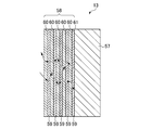
- the multilayer film 58 is provided on the surface of the pedestal 57.
- the multilayer film 58 is formed by a first layer 59 formed of a hydrogen storage metal or a hydrogen storage alloy, and a second layer 60 formed of a hydrogen storage metal, a hydrogen storage alloy or ceramics different from the first layer 59.
- a dissimilar substance interface 61 is formed between the pedestal 57, the first layer 59, and the second layer 60.
- the thickness of the first layer 59 and the thickness of the second layer 60 are preferably less than 1000 nm, respectively. When the thickness of each of the first layer 59 and the second layer 60 is 1000 nm or more, it becomes difficult for hydrogen to permeate through the multilayer film 58. Further, when the thickness of each of the first layer 59 and the second layer 60 is less than 1000 nm, it is possible to maintain a nanostructure that does not exhibit bulk characteristics.
- the thickness of each of the first layer 59 and the second layer 60 is more preferably less than 500 nm. When the thickness of each of the first layer 59 and the second layer 60 is less than 500 nm, it is possible to maintain a nanostructure that does not completely exhibit bulk characteristics.
- the multilayer film 58 has a structure in which the first layer 59 and the second layer 60 are alternately laminated in this order on the surface of the pedestal 57.
- the first layer 59 and the second layer 60 each have five layers. The number of layers of the first layer 59 and the second layer 60 may be changed as appropriate.
- the multilayer film 58 may have a structure in which the second layer 60 and the first layer 59 are alternately laminated in this order on the surface of the pedestal 57.
- the multilayer film 58 may have one or more first layer 59 and one or more second layer 60, and one or more dissimilar substance interfaces 61 may be formed.
- the heating element 13 occludes hydrogen through the pedestal 57 and the multilayer film 58 when the hydrogen-based gas is supplied to the closed container 11.
- the heating element 13 maintains a state in which hydrogen is occluded in the pedestal 57 and the multilayer film 58 even when the supply of the hydrogen-based gas to the closed container 11 is stopped.
- the heating of the heating element 13 is started by the fluid, the hydrogen occluded in the pedestal 57 and the multilayer film 58 is released, and quantum diffusion is performed while hopping the inside of the multilayer film 58. It is known that hydrogen is light and quantum diffuses while hopping the sites (octohedral and tetrahedral sites) occupied by hydrogen of a certain substance A and substance B.
- hydrogen permeates the interface 61 between different substances by quantum diffusion to generate excess heat equal to or higher than the temperature of the fluid.
- the heat generation method using the heat generating device 10 includes a hydrogen storage step of supplying hydrogen-based gas to the hollow portion 26 of the closed container 11 to store hydrogen contained in the hydrogen-based gas in the heating element 13, and a closed container. It has a hydrogen release step of releasing hydrogen stored in the heating element 13 by performing vacuum exhaust of the hollow portion 26 of 11 and heating of the heating element 13. The hydrogen storage step and the hydrogen release step may be repeated.
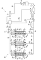
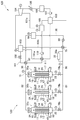
- the circulation line 30 of the heating device 70 includes a steam tank 72, a reservoir tank 73, a deaerator 74, a preheater 75, control valves 76a and 76b, and a pump 77a. , 77b are provided.
- the control valve 76a, the steam tank 72, the steam turbine 71, the cooling unit 32, the reservoir tank 73, the pump 77a, the deaerator 74, and the pump 77b are arranged in this order from the fluid outlet 24 of the closed container 11.
- a preheater 75, a heating unit 33, and a control valve 76b are provided.
- the deaerator 74, the preheater 75, the control valves 76a and 76b, and the pumps 77a and 77b are electrically connected to the control unit 16.
- the heating element 133 has a pedestal 57 and a multilayer film 134.
- the multilayer film 134 further has a third layer 135 in addition to the first layer 59 and the second layer 60.
- the description of the pedestal 57, the first layer 59, and the second layer 60 will be omitted.
- the third layer 135 is formed of a hydrogen storage metal, a hydrogen storage alloy, or ceramics different from those of the first layer 59 and the second layer 60.
- the thickness of the third layer 135 is preferably less than 1000 nm. In FIG.
- first layer 59-third layer 135-second layer 60 Pd-CaO-Ni, Pd-Y 2 O 3 -Ni, Pd-TiC-Ni, Pd-LaB 6 -Ni, Ni-CaO-Cu, Ni-Y 2 O 3 -Cu, Ni-TiC-Cu, Ni-LaB 6 -Cu, Ni-Co-Cu, Ni-CaO-Cr, Ni-Y 2 O 3 -Cr, Ni-TiC-Cr, Ni-LaB 6 -Cr, Ni-CaO-Fe, Ni-Y 2 O 3 -Fe, Ni -TiC-Fe, Ni-LaB 6 -Fe, Ni-Cr-Fe, Ni-CaO-Mg, Ni-Y 2 O 3 -Mg, Ni-TiC-Mg, Ni-LaB 6 -Mg,
- the first layer 59 and the fourth layer 145 are laminated in this order.
- the first layer 59, the second layer 60, the third layer 135, and the fourth layer 145 have the first layer 59, the fourth layer 145, the first layer 59, the third layer 135, and the first layer 145 on the surface of the pedestal 57.
- the first layer 59 and the second layer 60 may be laminated in this order. That is, in the multilayer film 144, the second layer 60, the third layer 135, and the fourth layer 145 are laminated in an arbitrary order, and the second layer 60, the third layer 135, and the fourth layer 145 are placed in the first layer. It has a laminated structure with one layer 59.
- the multilayer film 144 may have one or more fourth layers 145.
- the dissimilar substance interface 146 formed between the first layer 59 and the fourth layer 145 allows hydrogen atoms to permeate in the same manner as the dissimilar substance interface 61 and the dissimilar substance interface 136.
- the fourth layer 145 is formed of, for example, Ni, Pd, Cu, Cr, Fe, Mg, Co, an alloy thereof, SiC, CaO, Y 2 O 3 , TiC, or LaB 6 .
- the alloy forming the fourth layer 145 is preferably an alloy composed of two or more of Ni, Pd, Cu, Cr, Fe, Mg, and Co.
- an alloy obtained by adding an additive element to Ni, Pd, Cu, Cr, Fe, Mg, and Co may be used as the alloy forming the fourth layer 145.
- CO 2 contained in the exhaust gas is adsorbed on an adsorbent such as activated carbon or zeolite, and the adsorbent on which the CO 2 is adsorbed is heated to desorb CO 2 from the adsorbent.
- a fluid heated by a heating element can be used as a heat energy source for heating the absorption liquid that has absorbed CO 2.
- a fluid heated by a heating element can be used as a heat energy source for heating the adsorbent on which CO 2 is adsorbed in the physical adsorption method.
- CH 4 methane
- H 2 methane
- CH 4 is produced from the raw material gas by bringing the raw material gas containing CO 2 and H 2 into contact with the catalyst using a catalyst that promotes the reaction between CO 2 and H 2 (methanation reaction). If the temperature of the gas is low, the reaction does not proceed sufficiently. Therefore, the metanation reaction can be allowed to proceed by using the fluid heated by the heating element as the heat energy source as the heat energy source for heating the raw material gas containing CO 2 and H 2.
- ammonium iodide NH 4 I
- a fluid heated by a heating element can be used as a heat energy source for thermally decomposing ammonium iodide.
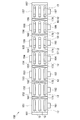
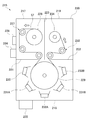
- FIG. 22 is a heating element manufacturing apparatus 150 that manufactures the heating element 13 by using a sputtering method.
- the heating element manufacturing apparatus 150 implements a DC (Direct Current) magnetron sputtering method as a sputtering method, and directly forms the heating element 13 on the outer surface of the tubular body 12.
- DC Direct Current
- the heating element manufacturing apparatus 150 carries a plurality of cylinders 12 into the loading chamber 151 and directly forms the heating element 13 on the outer surface of each cylinder 12, but loads one cylinder 12. It may be carried into the chamber 151 and the heating element 13 may be directly formed on the outer surface of the tubular body 12.
- the heating element manufacturing apparatus 150 is provided between the first gate valve 161 provided between the load chamber 151 and the preheating chamber 152, and the first gate valve 161 provided between the preheating chamber 152 and the spatter etching chamber 153.
- the first gate valve 161 opens and closes the first loading / unloading section 171 between the load chamber 151 and the preheating chamber 152.
- the second gate valve 162 opens and closes the second carry-in / out portion 172 between the preheating chamber 152 and the sputter etching chamber 153.
- the third gate valve 163 opens and closes the third carry-in / out portion 173 between the sputtering etching chamber 153 and the pedestal forming chamber 154.
- the fourth gate valve 164 opens and closes the fourth carry-in / out portion 174 between the pedestal forming chamber 154 and the first layer forming chamber 155.
- the load chamber 151 has a carry-in unit 191 for carrying in the cylinder 12, and after the cylinder 12 is carried in from the carry-in unit 191, the first vacuum generation unit is closed with the carry-in unit 191 and the first gate valve 161 closed. It is evacuated by 181. After the vacuum exhaust of the load chamber 151, the first gate valve 161 is opened, and the tubular body 12 is conveyed from the load chamber 151 to the preheating chamber 152 via the first loading / unloading section 171.
- the sputter etching chamber 153 is evacuated by the third vacuum generating unit 183 with the second gate valve 162 and the third gate valve 163 closed.
- the sputter-etching chamber 153 has a sputter-etching electrode 193, and sputter-etches the cylinder 12 with the spatter-etching electrode 193 while rotating the cylinder 12.
- the sputter etching electrode 193 is formed on the surface of the tubular body 12 by, for example, adjusting the flow rate of Ar gas so that the pressure of Ar is about 0.1 to 1 Pa and applying a high frequency (RF; Radio Frequency) of 13.56 MHz. Removes organic substances and metal oxides.
- the third gate valve 163 is opened, and the tubular body 12 is conveyed from the sputter etching chamber 153 to the pedestal forming chamber 154 via the third carry-in / out portion 173.
- the pedestal forming sputtering electrode 194 is formed on the cylinder 12 by, for example, adjusting the flow rate of Ar gas to set the Ar pressure to about 0.1 to 1 Pa and applying DC power of about 0.1 to 500 kW / m 2.
- the pedestal 57 is formed on the surface. The thickness of the pedestal 57 can be controlled by adjusting the magnitude of the DC power and the rotation speed of the cylinder 12.
- the first layer forming chamber 155 is evacuated to, for example, about 1E-5Pa by the fifth vacuum generating unit 185 with the fourth gate valve 164 and the fifth gate valve 165 closed.
- the first layer forming chamber 155 has a first layer film forming sputtering electrode 195, and forms the first layer 59 on the pedestal 57 by the first layer forming sputtering electrode 195 while rotating the tubular body 12.
- the first layer film forming sputtering electrode 195 has a target material (not shown) of a hydrogen storage metal or a hydrogen storage alloy forming the first layer 59.
- the front surface of the target material faces the pedestal 57.
- a magnet (not shown) is arranged on the back surface of the target material.
- the first layer film forming sputtering electrode 195 is a pedestal, for example, by adjusting the flow rate of Ar gas to set the Ar pressure to about 0.1 to 1 Pa and applying DC power to about 0.1 to 500 kW / m 2.
- the first layer 59 is formed on the 57.
- the thickness of the first layer 59 can be controlled by adjusting the magnitude of the DC power and the rotation speed of the cylinder 12.
- the second layer forming chamber 156 is evacuated to, for example, about 1E-5Pa by the sixth vacuum generating unit 186 with the fifth gate valve 165 and the sixth gate valve 166 closed.
- the second layer forming chamber 156 has a second layer film forming sputtering electrode 196, and forms the second layer 60 on the pedestal 57 by the second layer film forming sputtering electrode 196 while rotating the tubular body 12.
- the second layer film forming sputter electrode 196 has a target material (not shown) of a hydrogen storage metal, a hydrogen storage alloy, or a ceramic that forms the second layer 60.
- the front surface of the target material faces the pedestal 57.
- a magnet (not shown) is arranged on the back surface of the target material.
- the second layer film forming sputtering electrode 196 is a pedestal, for example, by adjusting the flow rate of Ar gas to set the Ar pressure to about 0.1 to 1 Pa and applying DC power to about 0.1 to 500 kW / m 2.
- the second layer 60 is formed on the 57.
- the second layer film forming sputtering electrode 196 is configured to apply RF.
- a multilayer film 58 (see FIG. 5) composed of the first layer 59 and the second layer 60 is formed on the surface of the pedestal 57. In this way, the heating element 13 is directly formed on the outer surface of the tubular body 12.
- the thickness of the second layer 60 can be controlled by adjusting the magnitude of the DC power and the rotation speed of the cylinder 12.
- the sixth gate valve 166 is opened, and the tubular body 12 is conveyed from the second layer forming chamber 156 to the unload chamber 157 via the sixth loading / unloading portion 176.
- the unload chamber 157 has a carry-out unit 197 for carrying out the tubular body 12, and the sixth vacuum generation part 186 is opened to the atmosphere with the carry-out part 197 and the sixth gate valve 166 closed. From the unload chamber 157 in the atmospheric pressure state, the tubular body 12 on which the heating element 13 is formed can be taken out via the carry-out portion 197.
- the heating element manufacturing apparatus 150 is provided with first to seventh vacuum generating units 181 to 187 that evacuate each processing chamber, but the vacuum generating unit may be shared by several processing chambers. Good.
- the pressure in each processing chamber can be controlled, for example, by adjusting the flow rate of Ar gas using an orifice valve.
- the rotation speed of the cylinder 12 is set based on the film thickness, etching rate or film formation rate to be etched or filmed.
- the film thickness to be etched or filmed is X (nm) and the etching rate or film formation rate is Y (nm / min)
- the heating element manufacturing device 150 can be made smaller as a whole by being configured to carry in a plurality of short tubular bodies 12 having a length of, for example, about 50 cm to 2 m.
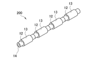
- the heating unit 200 may be configured by connecting short cylinders 12 on which the heating element 13 is formed.
- the heating element manufacturing device 150 is not limited to the one that manufactures the heating element 13 having a structure in which the multilayer film 58 is formed on the pedestal 57.
- a heating element 133 having a structure in which a multilayer film 134 is formed on a pedestal 57, or a heating element 143 having a structure in which a multilayer film 144 is formed on a pedestal 57 may be manufactured.
- the heating element manufacturing apparatus for manufacturing the heating element 133 has a third layer film forming sputter electrode for forming the third layer 135 on the pedestal 57 in addition to the first layer forming chamber 155 and the second layer forming chamber 156.
- a layer forming chamber is further provided.
- the third layer film forming sputtering electrode has a target material of a hydrogen storage metal or a hydrogen storage alloy forming the third layer 135. Similar to the first layer film forming sputtering electrode or the second layer film forming sputtering electrode, the third layer film forming sputtering electrode has the thickness of the third layer 135 by adjusting the magnitude of the DC power and the rotation speed of the cylinder 12. Can be controlled.
- the thickness of the pedestal 57 constituting the heating elements 13, 133, 143 is not particularly limited and can be changed as appropriate.
- a film-shaped heating element (hereinafter referred to as a film-shaped heating element) can be formed by thinning the pedestal 57 to form a film and providing the multilayer films 58, 134, 144 on the film-shaped pedestal 57. ..
- the film-shaped heating element will be described in detail.
- the film-shaped heating element 213 is wound around the outer surface of the tubular body 12.
- the film-shaped heating element 213 may be spirally wound around the outer surface of the tubular body 12 with a gap.
- the film-shaped heating element 213 has a spiral shape on the outer surface of the tubular body 12 so that at least a part of the film-shaped heating elements 213 adjacent to each other in the central axis C direction of the tubular body 12 overlaps in the radial direction of the tubular body 12. You may wrap it around.
- the film-shaped heating element 213 has the same structure as the heating element 13 (see FIG. 5). That is, the film-shaped heating element 213 has a pedestal 57 and a multilayer film 58.
- the pedestal 57 and the multilayer film 58 constituting the film-shaped heating element 213 are in the form of a film.
- the thickness of the pedestal 57 is preferably in the range of 1 ⁇ m or more and 5000 ⁇ m or less, and more preferably in the range of 100 ⁇ m or more and 600 ⁇ m or less.
- the thickness of the multilayer film 58 is preferably in the range of 0.02 ⁇ m or more and 10 ⁇ m or less, and more preferably in the range of 2 ⁇ m or more and 6 ⁇ m or less.
- the thickness of the film-shaped heating element 213 is preferably in the range of 1.02 ⁇ m or more and 5010 ⁇ m or less, and more preferably in the range of 102 ⁇ m or more and 606 ⁇ m or less.
- the thickness of the pedestal 57, the thickness of the multilayer film 58, and the thickness of the film-shaped heating element 213 are not limited to the above values, and are appropriately designed so that a desired output can be obtained as a heating device using the film-shaped heating element 213. be able to.
- the film-shaped heating element 213 has the same structure as the heating element 13 in this example, but may have the same structure as the heating element 133 (see FIG. 19), that is, a pedestal 57 and a multilayer film 134. Further, the film-shaped heating element 213 may have the same structure as the heating element 143 (see FIG. 20), that is, one having a pedestal 57 and a multilayer film 144.
- the multilayer film 134 or the multilayer film 144 constituting the film-shaped heating element 213 is in the form of a film.
- the film-shaped heating element 213 and the tubular body 12 are joined by, for example, spot welding.
- the film-shaped heating element 213 and the tubular body 12 are joined by spot welding the film-shaped heating element 213 around the outer surface of the tubular body 12 at equal intervals in the central axis C direction of the tubular body 12.
- the spot-welded portion has a high temperature, the characteristics of the film-shaped heating element 213 are hardly deteriorated because the diameter of the spot-welded portion is about 1 mm and the time in the high temperature state is several seconds.
- the location where the film-shaped heating element 213 and the tubular body 12 are joined is not particularly limited.
- the film-shaped heating element 213 has the pedestal 57 and the multilayer film 58, it has the same action and effect as the heating element 13. That is, since the film-shaped heating element 213 uses hydrogen to generate heat, it does not generate greenhouse gases such as carbon dioxide. Further, the hydrogen used to generate heat in the film-shaped heating element 213 is inexpensive because it can be generated from water. Further, the heat generated by the film-shaped heating element 213 is considered safe because there is no chain reaction unlike the fission reaction. Therefore, the film heating element 213 can be used as an inexpensive, clean, and safe energy source. Further, the film-shaped heating element 213 is excellent in followability to a curved surface while having flexibility because the pedestal 57 and the multilayer film 58 are in the form of a film.
- FIG. 25 is a film-shaped heating element manufacturing apparatus 215 that manufactures a film-shaped heating element 213 using a sputtering method.
- the film-shaped heating element manufacturing apparatus 215 implements a DC magnetron sputtering method as a sputtering method in this example.
- the film-shaped heating element manufacturing apparatus 215 continuously conveys a long film-shaped pedestal 57 by a roller-to-roller method, and forms a multilayer film 58 on the surface of the pedestal 57.
- the sputtering gas is argon (Ar) gas in this example, but a known gas may be used.
- Ar argon
- the shape and material of the vacuum chamber 220 are not particularly limited as long as they can withstand a reduced pressure state.
- the unwinding chamber 217 includes an unwinding roller 226 around which a long film-shaped pedestal 57 is wound, a first conveying roller portion 227 that conveys the pedestal 57 unwound from the unwinding roller 226, and a first conveying roller. It has a heating unit 228 that heats the pedestal 57 conveyed by the unit 227.
- the unwinding roller 226 has a motor (not shown) and is rotated by driving the motor.
- the first transport roller unit 227 is composed of, for example, a free roller and a tension measuring roller.
- the heating unit 228 removes the water adsorbed on the surface of the pedestal 57 by heating the pedestal 57 so that the surface temperature is, for example, 200 to 350 ° C.
- the heating unit 228 is not particularly limited as long as it can heat the pedestal 57 to a desired temperature, and for example, a lamp heating method, an infrared heating method, an induction heating method, or the like can be used.
- the film forming chamber 218 forms a film forming roller 229 that conveys the pedestal 57 carried out from the unwinding chamber 217, a sputter etching electrode 230 that sputter etches the surface of the pedestal 57, and a first layer 59 on the pedestal 57. It has first-layer film-forming sputtering electrodes 231A and 231B, and second-layer film-forming sputtering electrodes 232A and 232B that form a second layer 60 on a pedestal 57.
- sputter etching electrode 230 for example, by adjusting the flow rate of Ar gas to set the Ar pressure to about 0.1 to 1 Pa and applying RF of 13.56 MHz, organic substances, metal oxides, etc. on the surface of the pedestal 57 can be obtained. To remove.
- the second layer film forming sputtering electrode 232A and the second layer film forming sputtering electrode 232B have the same configuration as each other.
- the second layer film-forming sputter electrodes 232A and 232B have a target material (not shown) of a hydrogen storage metal, a hydrogen storage alloy, or a ceramic that forms the second layer 60.
- the front surface of the target material faces the pedestal 57.
- a magnet (not shown) is arranged on the back surface of the target material.
- the second layer film forming sputtering electrodes 232A and 232B for example, by adjusting the flow rate of Ar gas to set the Ar pressure to about 0.1 to 1 Pa and applying DC power to about 0.1 to 500 kW / m 2.
- the second layer film forming sputtering electrode 232A forms the second layer 60 on the surface of the first layer 59 formed by the first layer film forming sputtering electrode 231A.
- the first layer film forming sputtering electrode 231B forms the first layer 59 on the surface of the second layer 60 formed by the second layer film forming sputtering electrode 232A.
- the second layer film forming sputtering electrode 232B forms the second layer 60 on the surface of the first layer 59 formed by the first layer film forming sputtering electrode 231B. In this way, in the film forming chamber 218, a multilayer film 58 composed of the first layer 59 and the second layer 60 is formed on the surface of the pedestal 57.
- the take-up chamber 219 has a second transport roller portion 233 that conveys the pedestal 57 carried out from the film forming chamber 218, and a take-up roller 234 that winds up the pedestal 57 conveyed by the second transport roller portion 233.
- the film-like material wound around the take-up roller 234 is the film-like heating element 213.
- the second transport roller unit 233 is composed of, for example, a free roller and a tension measuring roller.
- the take-up roller 234 has a motor (not shown) and is rotated by driving the motor. The tension based on the peripheral speed difference between the take-up roller 234 and the film forming roller 229 is measured by the tension measuring roller of the second transport roller portion 233.
- a plurality of short film heating elements 213 are prepared by cutting a long film heating element 213 to a predetermined length, and a plurality of short film heating elements 213 are placed on the outer surface of one cylinder 12 with each other. It may be provided at intervals.
- step processing for example, by turning the power ON / OFF or adjusting the input power, the time for heating, sputter etching, and film formation can be set independently. Further, the time for forming the film may be set by opening and closing the shutter that shields the target material.
- the fourth layer film forming sputtering electrode of the fourth layer 145 is formed by adjusting the magnitude of DC power and the transport speed of the pedestal 57. The thickness can be controlled.
Landscapes
- Chemical & Material Sciences (AREA)
- Engineering & Computer Science (AREA)
- Organic Chemistry (AREA)
- Chemical Kinetics & Catalysis (AREA)
- Combustion & Propulsion (AREA)
- Inorganic Chemistry (AREA)
- General Engineering & Computer Science (AREA)
- Physics & Mathematics (AREA)
- Thermal Sciences (AREA)
- Mechanical Engineering (AREA)
- Geology (AREA)
- General Life Sciences & Earth Sciences (AREA)
- Environmental & Geological Engineering (AREA)
- Life Sciences & Earth Sciences (AREA)
- General Chemical & Material Sciences (AREA)
- Materials Engineering (AREA)
- Fuel Cell (AREA)
- Physical Or Chemical Processes And Apparatus (AREA)
- Hydrogen, Water And Hydrids (AREA)
- Instantaneous Water Boilers, Portable Hot-Water Supply Apparatuses, And Control Of Portable Hot-Water Supply Apparatuses (AREA)
- Sorption Type Refrigeration Machines (AREA)
- Engine Equipment That Uses Special Cycles (AREA)
- Buildings Adapted To Withstand Abnormal External Influences (AREA)
- Photovoltaic Devices (AREA)
- Medicines That Contain Protein Lipid Enzymes And Other Medicines (AREA)
Priority Applications (9)
| Application Number | Priority Date | Filing Date | Title |
|---|---|---|---|
| EP20890402.9A EP4063319A4 (en) | 2019-11-19 | 2020-11-18 | HEAT GENERATING DEVICE, HEAT UTILIZATION SYSTEM AND FILM-TYPE HEAT GENERATING ELEMENT |
| AU2020389304A AU2020389304B2 (en) | 2019-11-19 | 2020-11-18 | Heat generation device, heat utilization system and film-like heat generation element |
| BR112022009628A BR112022009628A2 (pt) | 2019-11-19 | 2020-11-18 | Dispositivo de geração de calor, sistema de utilização de calor e elemento de geração de calor como filme |
| CA3158751A CA3158751A1 (en) | 2019-11-19 | 2020-11-18 | Heat generation device, heat utilization system and film-like heat generation element |
| JP2021558432A JP7651185B2 (ja) | 2019-11-19 | 2020-11-18 | 発熱装置、および熱利用システム |
| KR1020227020309A KR20220103990A (ko) | 2019-11-19 | 2020-11-18 | 발열 장치, 열 이용 시스템 및 필름상 발열체 |
| CN202080080722.6A CN114746712B (zh) | 2019-11-19 | 2020-11-18 | 发热装置、热利用系统及膜状发热体 |
| US17/778,141 US12618592B2 (en) | 2019-11-19 | 2020-11-18 | Heat generation device, heat utilization system and film-like heat generation element |
| TW109140560A TWI861292B (zh) | 2019-11-19 | 2020-11-19 | 發熱裝置、熱利用系統及膜狀發熱體 |
Applications Claiming Priority (2)
| Application Number | Priority Date | Filing Date | Title |
|---|---|---|---|
| JP2019208483 | 2019-11-19 | ||
| JP2019-208483 | 2019-11-19 |
Publications (1)
| Publication Number | Publication Date |
|---|---|
| WO2021100784A1 true WO2021100784A1 (ja) | 2021-05-27 |
Family
ID=75981288
Family Applications (1)
| Application Number | Title | Priority Date | Filing Date |
|---|---|---|---|
| PCT/JP2020/043076 Ceased WO2021100784A1 (ja) | 2019-11-19 | 2020-11-18 | 発熱装置、熱利用システムおよびフィルム状発熱体 |
Country Status (9)
| Country | Link |
|---|---|
| EP (1) | EP4063319A4 (https=) |
| JP (1) | JP7651185B2 (https=) |
| KR (1) | KR20220103990A (https=) |
| CN (1) | CN114746712B (https=) |
| AU (1) | AU2020389304B2 (https=) |
| BR (1) | BR112022009628A2 (https=) |
| CA (1) | CA3158751A1 (https=) |
| TW (1) | TWI861292B (https=) |
| WO (1) | WO2021100784A1 (https=) |
Cited By (10)
| Publication number | Priority date | Publication date | Assignee | Title |
|---|---|---|---|---|
| WO2022234798A1 (ja) * | 2021-05-07 | 2022-11-10 | 株式会社クリーンプラネット | 発熱装置 |
| WO2022234797A1 (ja) * | 2021-05-07 | 2022-11-10 | 株式会社クリーンプラネット | 発熱装置 |
| WO2023026889A1 (ja) * | 2021-08-27 | 2023-03-02 | 株式会社クリーンプラネット | 発熱装置およびボイラー |
| WO2023145282A1 (ja) * | 2022-01-31 | 2023-08-03 | 株式会社クリーンプラネット | 熱利用システム及び発熱装置 |
| JP2023117024A (ja) * | 2022-02-10 | 2023-08-23 | トヨタ自動車株式会社 | 出力取出装置 |
| US20230271826A1 (en) * | 2022-02-28 | 2023-08-31 | Hyundai Motor Company | Hydrogen compression system |
| WO2025013472A1 (ja) * | 2023-07-07 | 2025-01-16 | 株式会社クリーンプラネット | 発熱システム、火力発電システム、及び発熱方法 |
| EP4382625A4 (en) * | 2021-08-31 | 2025-05-07 | Clean Planet Inc. | Hydrogen heating device for blast furnace, hydrogen heating process for blast furnace and blast furnace operating process |
| WO2025187498A1 (ja) * | 2024-03-04 | 2025-09-12 | 株式会社クリーンプラネット | 発熱装置 |
| WO2026070182A1 (ja) * | 2024-09-24 | 2026-04-02 | 株式会社クリーンプラネット | 発熱システム、発電システム、火力発電システムおよび発熱方法 |
Families Citing this family (1)
| Publication number | Priority date | Publication date | Assignee | Title |
|---|---|---|---|---|
| KR102805057B1 (ko) * | 2023-03-28 | 2025-05-13 | (주)원익머트리얼즈 | 암모니아 기화기 시스템 |
Citations (12)
| Publication number | Priority date | Publication date | Assignee | Title |
|---|---|---|---|---|
| JPS5292144A (en) * | 1976-01-29 | 1977-08-03 | Agency Of Ind Science & Technol | Electric power accumulating-type heating equipment using metal-hydroge n compounds |
| JPH06257864A (ja) * | 1993-03-01 | 1994-09-16 | Nippon Telegr & Teleph Corp <Ntt> | 発熱装置 |
| JPH1172200A (ja) * | 1997-08-29 | 1999-03-16 | Sanyo Electric Co Ltd | 水素吸蔵合金収容容器 |
| WO2000077266A1 (fr) * | 1999-06-11 | 2000-12-21 | Sumitomo Electric Industries, Ltd. | Materiau en couches bloquant l'hydrogene |
| JP2004025012A (ja) * | 2002-06-25 | 2004-01-29 | Yoichi Kadokami | ガス吸蔵材料並びにガスの吸蔵及び排出方法 |
| JP2004053208A (ja) * | 2002-07-23 | 2004-02-19 | Denso Corp | 水素消費機器における加熱装置 |
| JP2004077200A (ja) * | 2002-08-12 | 2004-03-11 | Mitsubishi Heavy Ind Ltd | 元素変換体およびその製造方法 |
| WO2015008859A2 (ja) * | 2013-07-18 | 2015-01-22 | 水素技術応用開発株式会社 | 反応体、発熱装置及び発熱方法 |
| WO2018062115A1 (ja) * | 2016-09-28 | 2018-04-05 | 株式会社クリーンプラネット | 発熱システム |
| WO2018230447A1 (ja) * | 2017-06-15 | 2018-12-20 | 株式会社クリーンプラネット | 発熱装置および発熱方法 |
| WO2020122097A1 (ja) * | 2018-12-11 | 2020-06-18 | 株式会社クリーンプラネット | 熱利用システムおよび発熱装置 |
| WO2020122098A1 (ja) * | 2018-12-11 | 2020-06-18 | 株式会社クリーンプラネット | 熱利用システムおよび発熱装置 |
Family Cites Families (7)
| Publication number | Priority date | Publication date | Assignee | Title |
|---|---|---|---|---|
| JPS61134593A (ja) * | 1984-11-30 | 1986-06-21 | Agency Of Ind Science & Technol | 水素吸蔵合金を使用した熱交換装置 |
| JP2936113B2 (ja) * | 1993-02-23 | 1999-08-23 | 日本電信電話株式会社 | 発熱体および発熱装置 |
| JPH07331233A (ja) * | 1994-06-15 | 1995-12-19 | Nippondenso Co Ltd | 蓄熱材およびこれを用いた蓄熱装置 |
| JPH09324960A (ja) * | 1996-06-05 | 1997-12-16 | Japan Steel Works Ltd:The | 水素吸蔵合金を用いた発熱または吸熱方法および装置 |
| US6293110B1 (en) * | 1999-12-17 | 2001-09-25 | Energy Conversion Devices, Inc. | Hydrogen cooled hydride storage unit |
| WO2002068882A1 (en) * | 2001-02-26 | 2002-09-06 | Ip Trading Japan Co., Ltd. | Device for thermoelectric transduction, air condition and refrigeration, using hydrogen occluding alloy unit |
| JP2008039108A (ja) * | 2006-08-08 | 2008-02-21 | Toyota Motor Corp | 水素貯蔵装置 |
-
2020
- 2020-11-18 BR BR112022009628A patent/BR112022009628A2/pt unknown
- 2020-11-18 CA CA3158751A patent/CA3158751A1/en active Pending
- 2020-11-18 AU AU2020389304A patent/AU2020389304B2/en active Active
- 2020-11-18 WO PCT/JP2020/043076 patent/WO2021100784A1/ja not_active Ceased
- 2020-11-18 CN CN202080080722.6A patent/CN114746712B/zh active Active
- 2020-11-18 JP JP2021558432A patent/JP7651185B2/ja active Active
- 2020-11-18 EP EP20890402.9A patent/EP4063319A4/en active Pending
- 2020-11-18 KR KR1020227020309A patent/KR20220103990A/ko active Pending
- 2020-11-19 TW TW109140560A patent/TWI861292B/zh active
Patent Citations (15)
| Publication number | Priority date | Publication date | Assignee | Title |
|---|---|---|---|---|
| JPS5292144A (en) * | 1976-01-29 | 1977-08-03 | Agency Of Ind Science & Technol | Electric power accumulating-type heating equipment using metal-hydroge n compounds |
| JPH06257864A (ja) * | 1993-03-01 | 1994-09-16 | Nippon Telegr & Teleph Corp <Ntt> | 発熱装置 |
| JPH1172200A (ja) * | 1997-08-29 | 1999-03-16 | Sanyo Electric Co Ltd | 水素吸蔵合金収容容器 |
| WO2000077266A1 (fr) * | 1999-06-11 | 2000-12-21 | Sumitomo Electric Industries, Ltd. | Materiau en couches bloquant l'hydrogene |
| JP2004025012A (ja) * | 2002-06-25 | 2004-01-29 | Yoichi Kadokami | ガス吸蔵材料並びにガスの吸蔵及び排出方法 |
| JP2004053208A (ja) * | 2002-07-23 | 2004-02-19 | Denso Corp | 水素消費機器における加熱装置 |
| JP2004077200A (ja) * | 2002-08-12 | 2004-03-11 | Mitsubishi Heavy Ind Ltd | 元素変換体およびその製造方法 |
| WO2015008859A2 (ja) * | 2013-07-18 | 2015-01-22 | 水素技術応用開発株式会社 | 反応体、発熱装置及び発熱方法 |
| WO2018062115A1 (ja) * | 2016-09-28 | 2018-04-05 | 株式会社クリーンプラネット | 発熱システム |
| WO2018230447A1 (ja) * | 2017-06-15 | 2018-12-20 | 株式会社クリーンプラネット | 発熱装置および発熱方法 |
| JP6548102B2 (ja) * | 2017-06-15 | 2019-07-24 | 株式会社クリーンプラネット | 発熱装置および発熱方法 |
| JP6696096B2 (ja) * | 2017-06-15 | 2020-05-20 | 株式会社クリーンプラネット | 発熱装置および発熱方法 |
| WO2020122097A1 (ja) * | 2018-12-11 | 2020-06-18 | 株式会社クリーンプラネット | 熱利用システムおよび発熱装置 |
| WO2020122098A1 (ja) * | 2018-12-11 | 2020-06-18 | 株式会社クリーンプラネット | 熱利用システムおよび発熱装置 |
| JP6749035B1 (ja) * | 2018-12-11 | 2020-09-02 | 株式会社クリーンプラネット | 熱利用システムおよび発熱装置 |
Non-Patent Citations (2)
| Title |
|---|
| A. KITAMURAA. TAKAHASHIK. TAKAHASHIR. SETOT. HATANOY. IWAMURAT. ITOHJ. KASAGIM. NAKAMURAM. UCHIMURA: "Excess heat evolution from nanocomposite samples under exposure to hydrogen isotope gases", INTERNATIONAL JOURNAL OF HYDROGEN ENERGY, vol. 43, 2018, pages 16187 - 16200 |
| See also references of EP4063319A4 |
Cited By (14)
| Publication number | Priority date | Publication date | Assignee | Title |
|---|---|---|---|---|
| WO2022234797A1 (ja) * | 2021-05-07 | 2022-11-10 | 株式会社クリーンプラネット | 発熱装置 |
| WO2022234798A1 (ja) * | 2021-05-07 | 2022-11-10 | 株式会社クリーンプラネット | 発熱装置 |
| WO2023026889A1 (ja) * | 2021-08-27 | 2023-03-02 | 株式会社クリーンプラネット | 発熱装置およびボイラー |
| JP2023033000A (ja) * | 2021-08-27 | 2023-03-09 | 株式会社クリーンプラネット | 発熱装置およびボイラー |
| JP7829904B2 (ja) | 2021-08-27 | 2026-03-16 | 株式会社クリーンプラネット | 発熱装置およびボイラー |
| EP4382625A4 (en) * | 2021-08-31 | 2025-05-07 | Clean Planet Inc. | Hydrogen heating device for blast furnace, hydrogen heating process for blast furnace and blast furnace operating process |
| WO2023145282A1 (ja) * | 2022-01-31 | 2023-08-03 | 株式会社クリーンプラネット | 熱利用システム及び発熱装置 |
| JP2023111758A (ja) * | 2022-01-31 | 2023-08-10 | 株式会社クリーンプラネット | 熱利用システムおよび発熱装置 |
| JP2023117024A (ja) * | 2022-02-10 | 2023-08-23 | トヨタ自動車株式会社 | 出力取出装置 |
| US12258271B2 (en) * | 2022-02-28 | 2025-03-25 | Hyundai Motor Company | Hydrogen compression system |
| US20230271826A1 (en) * | 2022-02-28 | 2023-08-31 | Hyundai Motor Company | Hydrogen compression system |
| WO2025013472A1 (ja) * | 2023-07-07 | 2025-01-16 | 株式会社クリーンプラネット | 発熱システム、火力発電システム、及び発熱方法 |
| WO2025187498A1 (ja) * | 2024-03-04 | 2025-09-12 | 株式会社クリーンプラネット | 発熱装置 |
| WO2026070182A1 (ja) * | 2024-09-24 | 2026-04-02 | 株式会社クリーンプラネット | 発熱システム、発電システム、火力発電システムおよび発熱方法 |
Also Published As
| Publication number | Publication date |
|---|---|
| KR20220103990A (ko) | 2022-07-25 |
| US20230003461A1 (en) | 2023-01-05 |
| CN114746712B (zh) | 2025-09-26 |
| JP7651185B2 (ja) | 2025-03-26 |
| BR112022009628A2 (pt) | 2022-08-09 |
| AU2020389304B2 (en) | 2025-12-18 |
| EP4063319A4 (en) | 2023-12-20 |
| CN114746712A (zh) | 2022-07-12 |
| JPWO2021100784A1 (https=) | 2021-05-27 |
| CA3158751A1 (en) | 2021-05-27 |
| AU2020389304A1 (en) | 2022-07-07 |
| EP4063319A1 (en) | 2022-09-28 |
| TW202136146A (zh) | 2021-10-01 |
| TWI861292B (zh) | 2024-11-11 |
Similar Documents
| Publication | Publication Date | Title |
|---|---|---|
| JP7651185B2 (ja) | 発熱装置、および熱利用システム | |
| JP6749035B1 (ja) | 熱利用システムおよび発熱装置 | |
| TWI855013B (zh) | 熱利用系統及發熱裝置 | |
| JP7114108B2 (ja) | 熱利用システムおよび発熱装置 | |
| JP7488548B2 (ja) | 発熱装置 | |
| JP7822590B2 (ja) | 発熱装置及び熱利用システム | |
| US12618592B2 (en) | Heat generation device, heat utilization system and film-like heat generation element | |
| RU2826662C1 (ru) | Теплогенерирующее устройство, система утилизации тепла и пленочный теплогенерирующий элемент | |
| JP7829904B2 (ja) | 発熱装置およびボイラー | |
| HK40069893A (en) | Heat generation device, heat utilization system and film-like heat generation element | |
| WO2023026767A1 (ja) | 水素製造システム | |
| JP2025009557A (ja) | 発熱システム、火力発電システム、及び発熱方法 | |
| JP7741534B2 (ja) | 発熱装置 | |
| JP7738084B2 (ja) | ガス製造装置 | |
| JP7772358B2 (ja) | 発熱装置および発熱素子の冷却方法 | |
| HK40106744A (zh) | 发热装置及锅炉 | |
| HK40110335A (zh) | 发热装置及发热元件的冷却方法 | |
| HK40057148A (en) | Heat utilization system, and heat generating device | |
| HK40057148B (en) | Heat utilization system, and heat generating device |
Legal Events
| Date | Code | Title | Description |
|---|---|---|---|
| 121 | Ep: the epo has been informed by wipo that ep was designated in this application |
Ref document number: 20890402 Country of ref document: EP Kind code of ref document: A1 |
|
| ENP | Entry into the national phase |
Ref document number: 2021558432 Country of ref document: JP Kind code of ref document: A |
|
| ENP | Entry into the national phase |
Ref document number: 3158751 Country of ref document: CA |
|
| REG | Reference to national code |
Ref country code: BR Ref legal event code: B01A Ref document number: 112022009628 Country of ref document: BR |
|
| ENP | Entry into the national phase |
Ref document number: 20227020309 Country of ref document: KR Kind code of ref document: A |
|
| NENP | Non-entry into the national phase |
Ref country code: DE |
|
| ENP | Entry into the national phase |
Ref document number: 2020890402 Country of ref document: EP Effective date: 20220620 |
|
| ENP | Entry into the national phase |
Ref document number: 2020389304 Country of ref document: AU Date of ref document: 20201118 Kind code of ref document: A |
|
| ENP | Entry into the national phase |
Ref document number: 112022009628 Country of ref document: BR Kind code of ref document: A2 Effective date: 20220518 |
|
| WWG | Wipo information: grant in national office |
Ref document number: 202217034686 Country of ref document: IN |