WO2021100475A1 - 演奏操作装置 - Google Patents
演奏操作装置 Download PDFInfo
- Publication number
- WO2021100475A1 WO2021100475A1 PCT/JP2020/041343 JP2020041343W WO2021100475A1 WO 2021100475 A1 WO2021100475 A1 WO 2021100475A1 JP 2020041343 W JP2020041343 W JP 2020041343W WO 2021100475 A1 WO2021100475 A1 WO 2021100475A1
- Authority
- WO
- WIPO (PCT)
- Prior art keywords
- circuit board
- key
- substrate holder
- passive circuit
- substrate
- Prior art date
- Legal status (The legal status is an assumption and is not a legal conclusion. Google has not performed a legal analysis and makes no representation as to the accuracy of the status listed.)
- Ceased
Links
Images
















Classifications
-
- G—PHYSICS
- G10—MUSICAL INSTRUMENTS; ACOUSTICS
- G10H—ELECTROPHONIC MUSICAL INSTRUMENTS; INSTRUMENTS IN WHICH THE TONES ARE GENERATED BY ELECTROMECHANICAL MEANS OR ELECTRONIC GENERATORS, OR IN WHICH THE TONES ARE SYNTHESISED FROM A DATA STORE
- G10H1/00—Details of electrophonic musical instruments
- G10H1/32—Constructional details
- G10H1/34—Switch arrangements, e.g. keyboards or mechanical switches specially adapted for electrophonic musical instruments
- G10H1/344—Structural association with individual keys
-
- G—PHYSICS
- G10—MUSICAL INSTRUMENTS; ACOUSTICS
- G10H—ELECTROPHONIC MUSICAL INSTRUMENTS; INSTRUMENTS IN WHICH THE TONES ARE GENERATED BY ELECTROMECHANICAL MEANS OR ELECTRONIC GENERATORS, OR IN WHICH THE TONES ARE SYNTHESISED FROM A DATA STORE
- G10H1/00—Details of electrophonic musical instruments
- G10H1/02—Means for controlling the tone frequencies, e.g. attack or decay; Means for producing special musical effects, e.g. vibratos or glissandos
- G10H1/04—Means for controlling the tone frequencies, e.g. attack or decay; Means for producing special musical effects, e.g. vibratos or glissandos by additional modulation
- G10H1/053—Means for controlling the tone frequencies, e.g. attack or decay; Means for producing special musical effects, e.g. vibratos or glissandos by additional modulation during execution only
- G10H1/055—Means for controlling the tone frequencies, e.g. attack or decay; Means for producing special musical effects, e.g. vibratos or glissandos by additional modulation during execution only by switches with variable impedance elements
- G10H1/0555—Means for controlling the tone frequencies, e.g. attack or decay; Means for producing special musical effects, e.g. vibratos or glissandos by additional modulation during execution only by switches with variable impedance elements using magnetic or electromagnetic means
-
- G—PHYSICS
- G10—MUSICAL INSTRUMENTS; ACOUSTICS
- G10H—ELECTROPHONIC MUSICAL INSTRUMENTS; INSTRUMENTS IN WHICH THE TONES ARE GENERATED BY ELECTROMECHANICAL MEANS OR ELECTRONIC GENERATORS, OR IN WHICH THE TONES ARE SYNTHESISED FROM A DATA STORE
- G10H1/00—Details of electrophonic musical instruments
- G10H1/32—Constructional details
- G10H1/34—Switch arrangements, e.g. keyboards or mechanical switches specially adapted for electrophonic musical instruments
- G10H1/344—Structural association with individual keys
- G10H1/346—Keys with an arrangement for simulating the feeling of a piano key, e.g. using counterweights, springs, cams
-
- G—PHYSICS
- G10—MUSICAL INSTRUMENTS; ACOUSTICS
- G10H—ELECTROPHONIC MUSICAL INSTRUMENTS; INSTRUMENTS IN WHICH THE TONES ARE GENERATED BY ELECTROMECHANICAL MEANS OR ELECTRONIC GENERATORS, OR IN WHICH THE TONES ARE SYNTHESISED FROM A DATA STORE
- G10H2220/00—Input/output interfacing specifically adapted for electrophonic musical tools or instruments
- G10H2220/155—User input interfaces for electrophonic musical instruments
- G10H2220/221—Keyboards, i.e. configuration of several keys or key-like input devices relative to one another
-
- G—PHYSICS
- G10—MUSICAL INSTRUMENTS; ACOUSTICS
- G10H—ELECTROPHONIC MUSICAL INSTRUMENTS; INSTRUMENTS IN WHICH THE TONES ARE GENERATED BY ELECTROMECHANICAL MEANS OR ELECTRONIC GENERATORS, OR IN WHICH THE TONES ARE SYNTHESISED FROM A DATA STORE
- G10H2220/00—Input/output interfacing specifically adapted for electrophonic musical tools or instruments
- G10H2220/155—User input interfaces for electrophonic musical instruments
- G10H2220/265—Key design details; Special characteristics of individual keys of a keyboard; Key-like musical input devices, e.g. finger sensors, pedals, potentiometers, selectors
- G10H2220/271—Velocity sensing for individual keys, e.g. by placing sensors at different points along the kinematic path for individual key velocity estimation by delay measurement between adjacent sensor signals
-
- G—PHYSICS
- G10—MUSICAL INSTRUMENTS; ACOUSTICS
- G10H—ELECTROPHONIC MUSICAL INSTRUMENTS; INSTRUMENTS IN WHICH THE TONES ARE GENERATED BY ELECTROMECHANICAL MEANS OR ELECTRONIC GENERATORS, OR IN WHICH THE TONES ARE SYNTHESISED FROM A DATA STORE
- G10H2220/00—Input/output interfacing specifically adapted for electrophonic musical tools or instruments
- G10H2220/155—User input interfaces for electrophonic musical instruments
- G10H2220/265—Key design details; Special characteristics of individual keys of a keyboard; Key-like musical input devices, e.g. finger sensors, pedals, potentiometers, selectors
- G10H2220/275—Switching mechanism or sensor details of individual keys, e.g. details of key contacts, hall effect or piezoelectric sensors used for key position or movement sensing purposes; Mounting thereof
-
- G—PHYSICS
- G10—MUSICAL INSTRUMENTS; ACOUSTICS
- G10H—ELECTROPHONIC MUSICAL INSTRUMENTS; INSTRUMENTS IN WHICH THE TONES ARE GENERATED BY ELECTROMECHANICAL MEANS OR ELECTRONIC GENERATORS, OR IN WHICH THE TONES ARE SYNTHESISED FROM A DATA STORE
- G10H2230/00—General physical, ergonomic or hardware implementation of electrophonic musical tools or instruments, e.g. shape or architecture
- G10H2230/045—Special instrument [spint], i.e. mimicking the ergonomy, shape, sound or other characteristic of a specific acoustic musical instrument category
- G10H2230/065—Spint piano, i.e. mimicking acoustic musical instruments with piano, cembalo or spinet features, e.g. with piano-like keyboard; Electrophonic aspects of piano-like acoustic keyboard instruments; MIDI-like control therefor
Definitions
- the present invention relates to a performance operation device.
- Key press detection is achieved by a contact sensor or a non-contact sensor. Since some of such non-contact sensors can be used as a distance sensor, the amount of key pressing can be continuously measured. As a result, the movement of the key can be accurately reflected in the pronunciation, and it can also be used for detecting after-touch.
- the non-contact type sensor includes, for example, an optical sensor.
- the optical sensor is affected by light entering from the outside and is affected by dirt.
- dirt For example, in electronic keyboard instruments, grease is used in moving parts. The scattering of this grease may contaminate the optical sensor.
- such a sensor may also be used in an acoustic piano or the like equipped with a sound source.
- a part of the housing for example, a roof plate
- Patent Document 1 As a non-contact type sensor that is not affected by this, for example, there is a magnetic induction type sensor (for example, Patent Document 1).
- the magnetic induction type sensor is a non-contact type
- one of the substrates on which the coil is placed needs to be attached to the part that moves with the key press, so it is attached corresponding to each key. Since many keys are used in a keyboard instrument, it is required to improve the efficiency of the work of attaching a substrate to each key in the manufacturing process of the keyboard instrument.
- One of the objects of the present invention is to facilitate the manufacturing process of a performance operation device using a magnetic induction type sensor.
- a performance operation device including a distance sensor, an operator, and a holding unit.
- the distance sensor includes a first substrate and a second substrate on which a conductor is arranged, respectively, and measures the distance between the first substrate and the second substrate.
- the operator can be operated by an operator.
- the holding portion holds the first substrate between the operator and the second substrate, and moves integrally with the operator.
- a performance operation device including a distance sensor, an operator, and a holding unit.
- the distance sensor includes a first substrate and a second substrate on which a conductor is arranged, respectively, and measures the distance between the first substrate and the second substrate.
- the operator can be operated by an operator.
- the first member is interlocked with the operator.
- the holding portion holds the first substrate between the first member and the second substrate, and moves integrally with the first member.
- the operator and the holding portion may be made of the same material.
- the first member and the holding portion may be made of the same material.
- the first member includes a portion that is elastically deformed, and even if the distance between the first substrate and the second substrate changes due to the elastic deformation of the first member by receiving a force from the operator. Good. In this case, the first member receives the force from the operator either directly or indirectly via another member.
- the holding portion may hold the first substrate detachably.
- the holding portion includes an elastic body, and when the elastic body is in the first state, the holding portion holds the first substrate, and the elastic body is elastically deformed from the first state. At this time, the holding of the first substrate by the holding portion may be released.
- the holding portion includes a first plate portion and a second plate portion, and the positional relationship between the first plate portion and the second plate portion can be changed, and the first plate portion and the second plate portion can be changed.
- the holding portion holds the first substrate, and the first plate portion and the second plate portion are separated from the first state. In the state, the holding of the first substrate by the holding portion may be released.
- FIG. 16 is a diagram illustrating a cross section in a state where a passive circuit board is attached to a substrate holder by closing the lid portion.
- the keyboard device according to the embodiment of the present invention will be described in detail with reference to the drawings.
- the embodiments shown below are examples of embodiments of the present invention, and the present invention is not construed as being limited to these embodiments.
- the same part or a part having a similar function is given the same code or a similar code (a code in which A, B, etc. are simply added after the numbers), and the process is repeated.
- the description of may be omitted.
- the dimensional ratio of the drawing may differ from the actual ratio for convenience of explanation, or a part of the configuration may be omitted from the drawing.
- a keyboard device used as an electronic keyboard instrument will be described.
- the key pressing operation can be detected by the magnetic induction type sensor.
- the key pressing operation is detected as, for example, the position of the key moved by the key pressing or the posture of the key.
- the keyboard device will be described in detail.
- FIG. 1 is a diagram illustrating a keyboard device according to the first embodiment of the present invention.
- the keyboard device 1 is an electronic keyboard instrument, and in this example, an electronic piano.
- the keyboard device 1 includes a key 10, a housing 50, a speaker 60, a sound source unit 80, and an operation unit 90.
- the side where the performer is present is defined as the front side
- the side opposite to the performer is defined as the rear side.
- left and right and up and down are also defined as directions when viewed from the performer.
- the plurality of keys 10 are arranged side by side in one direction.
- the scale direction in which a plurality of keys 10 are lined up is referred to as the left-right direction D1.
- D1a the left direction
- D1b the right direction
- D1b The direction orthogonal to the left-right direction D1
- the longitudinal direction of the key 10 is the same as the front-rear direction D2.
- D2a the front direction
- D2b the rear direction
- the direction orthogonal to both the left-right direction D1 and the front-rear direction D2 is referred to as the up-down direction D3 (see FIG. 2).
- the vertical direction D3 generally corresponds to the vertical direction when the keyboard device 1 is placed flat. That is, when the keyboard device 1 is placed horizontally and horizontally, the left-right direction D1 and the front-back direction D2 are directions in the horizontal plane.
- the upward direction is referred to as D3a and the downward direction is referred to as D3b.
- the key 10 can rotate with respect to the housing 50.
- the state in which the longitudinal direction of the key 10 and the front-rear direction D2 coincide with each other is included in the rotation range of the key 10.
- a speaker 60, a key pressing amount measuring unit 70, a sound source unit 80, and an operation unit 90 are arranged in the housing 50.
- the operation unit 90 is a device such as an operation button, a touch sensor, and a slider, receives an instruction for changing the type (timbre) and volume of the generated sound, and outputs a signal corresponding to the input operation to the sound source unit 80.
- the keyboard device 1 may include an interface for inputting / outputting signals to / from an external device.
- the interface includes, for example, a terminal for outputting a sound signal to an external device, a cable connection terminal for transmitting and receiving MIDI data, and the like.
- the key press amount measuring unit 70 includes a magnetic induction type sensor arranged for each of the plurality of keys 10. The sensor corresponding to each key 10 detects the position (pressing amount) of the key 10 in the rotation range.
- the key pressing amount measuring unit 70 outputs the key information for specifying any of the plurality of keys 10 and the pressing amount information corresponding to the pressed amount of the specified key 10 to the sound source unit 80.
- the pressing amount information may indicate the value of the pressing amount of the key 10 itself, or may be a value calculated from the pressing amount such as the speed calculated from the change in the pressing amount, and further, the information obtained by combining these. There may be.
- the combination of the key pressing amount measuring unit 70 and the key 10 is an example of an input device. The detailed configuration of the key press amount measuring unit 70 will be described later.
- the sound source unit 80 is a signal processing circuit that generates a sound signal in response to a performance operation on the key 10. Specifically, the sound source unit 80 generates a sound signal based on the information output from the key press amount measuring unit 70, and outputs the generated sound signal to the speaker 60. The speaker 60 amplifies and outputs the sound signal output from the sound source unit 80, thereby generating a sound corresponding to the sound signal.
- FIG. 2 is a diagram illustrating an internal structure (at the time of key release) of the keyboard device according to the first embodiment of the present invention.
- FIG. 3 is a diagram illustrating an internal structure (when a white key is pressed) of a keyboard device according to the first embodiment of the present invention.
- the configuration corresponding to the white key 10w is shown, and the configuration corresponding to the black key 10b is the same as the configuration corresponding to the white key 10w. Therefore, only the position of the black key 10b is shown, and other configurations are shown. It is omitted.
- the frame 20 is fixed to the housing 50 and supports a plurality of keys 10 arranged in the left-right direction D1.
- the frame 20 is made of a resin material in this example.
- the frame 20 includes a key guide portion 201, a key support portion 203, a rib portion 205, and a substrate holding portion 207.
- the key guide unit 201 regulates the movement of the key 10 in the left-right direction D1 by a member that slides on the key 10 below the front end portion of the key 10.
- the key support portion 203 supports the elastic portion 105 arranged at the rear end portion of the key 10. As the elastic portion 105 is deformed in the vertical direction, the free end side of the key 10 rotates about the key support portion 203. At this time, since the key 10 is restricted from moving in the left-right direction D1 by the key guide unit 201, the key 10 rotates about the left-right direction D1.
- the rib portion 205 is a plate-shaped member having a surface including the front-rear direction D2 and the vertical direction D3 (a surface having the left-right direction D1 as a normal line). A plurality of rib portions 205 are arranged side by side in the left-right direction D1. Each of the plurality of rib portions 205 is connected to each of the key guide portion 201, the key support portion 203, and the substrate holding portion 207.
- the board holding portion 207 is a plate-shaped member that holds the active circuit board 700.
- the active circuit board 700 is arranged on the upper surface side (key 10 side) of the board holding portion 207.
- a substrate holder 170 is fixed to the lower surface side (the substrate holding portion 207 side) of the key 10.
- the substrate holder 170 (holding portion) holds the passive circuit board 750 as described below.
- the active circuit board 700 and the passive circuit board 750 are elements that constitute the magnetic induction type sensor, and are components included in the key pressing amount measuring unit 70.
- the passive circuit board 750 is provided corresponding to each key 10.
- the active circuit board 700 is provided corresponding to a plurality of keys 10, but may be provided corresponding to each key 10.
- the load unit 30 (first member) is arranged corresponding to each key 10.
- the load unit 30 and the key 10 are interlocked by being connected to each other at the key connection unit 301 (sliding unit 307) of the load unit 30.
- the load portion 30 includes a key connection portion 301, a bearing 303, and a weight portion 305.
- the bearing 303 is provided corresponding to the shaft portion provided on the frame 20.
- the key connecting portion 301 is arranged on the side opposite to the weight portion 305 with respect to the bearing 303.
- the sliding portion 307 provided at one end of the key connecting portion 301 slides with respect to the load connecting portion 103 provided below the key 10.
- the load portion 30 has a center of gravity existing on the weight portion 305 side of the bearing 303.
- the load unit 30 places the weight unit 305 on the lower stopper 351 and holds the key 10 at the rest position (corresponding to when the key is released).
- the lower stopper 351 and the upper stopper 353 are supported by the frame 20.
- the load portion 30 rotates around the bearing 303 in conjunction with the rotation of the key 10, and the weight portion 305 moves upward. Then, it collides with the upper stopper 353 and further movement is restricted. At this time, as shown in FIG. 3, the active circuit board 700 and the passive circuit board 750 come close to each other.
- the pressing amount information output by the key pressing amount measuring unit 70 described above depends on the distance between the active circuit board 700 and the passive circuit board 750 (that is, the relative positional relationship between the active circuit board 700 and the passive circuit board 750). Information.
- the keyboard device 1 may not be provided with the load unit 30. In this case, a configuration may be provided to regulate the pressing range of the key 10.
- the key press amount measuring unit 70 includes the active circuit board 700 and the passive circuit board 750.
- the active circuit board 700 includes a coil (hereinafter, referred to as an active coil) for forming a magnetic field by the supplied electric power.
- the passive circuit board 750 including the coil hereinafter referred to as the passive coil
- the active circuit 770 anti-resonates according to the position of the passive coil due to magnetic coupling, that is, the circuit of the active circuit 770.
- the key pressing amount measuring unit 70 includes the distance sensor. Hereinafter, each configuration of the key pressing amount measuring unit 70 will be described in detail.
- FIG. 4 is a diagram illustrating an active circuit board according to the first embodiment of the present invention.
- the active circuit board 700 is a printed circuit board including a plurality of active circuits 770, a multiplexer 709, and various wirings (in addition to the ground wiring 708, a clock signal line, a selection signal line, an input signal line, an output signal line, and the like). Further, the active circuit board 700 includes a signal processing circuit (not shown).
- Each of the plurality of active circuits 770 is provided corresponding to each key 10.
- the two wires connecting the active circuit 770 and the multiplexer 709 correspond to the signal input unit 703a and the signal output unit 703b.
- the active circuit 770 includes an active coil 701 (conductor), capacitors 706a and 706b, and resistors 707a and 707b.
- the active coil 701 includes a wiring 701a formed on the substrate and formed on the upper surface side (key 10 side) of the substrate, and a wiring 701b provided on the lower surface side (board holding portion 207 side) of the substrate. In FIG. 4, the configuration arranged on the lower surface side of the substrate is shown by a broken line.
- the wiring 701a and the wiring 701b connected to each other form an active coil 701 in which two coils (first coil 701x and second coil 701y) are connected in series.
- the first coil 701x and the second coil 701y are arranged side by side along the front-rear direction D2, and the winding directions are opposite to each other.
- the fact that the winding direction is opposite here does not mean that the wiring is wound in the opposite direction due to the structure, but is wound so that the current flows in the opposite direction when the circuits are energized with each other. It means that it is.
- the magnetic flux formed by the active coil 701 is formed so as to pass through the second coil 701y immediately after exiting the first coil 701x.
- Capacitors 706a and 706b are connected in series between both ends of the active coil 701.
- a ground wire 708 is connected between the capacitor 706a and the capacitor 706b.
- the ground wiring 708 is commonly provided for each active circuit 770.
- a resistor 707a is connected between the capacitor 706a and the signal input unit 703a, and a resistor 707b is connected between the capacitor 706b and the signal output unit 703b.
- the active coil 701 forms a magnetic field corresponding to the input signal, and the active coil 701 and the passive coil 751 magnetically couple to output a signal.
- the signal output from unit 703b is modulated.
- the modulated signal is output to a signal processing circuit (not shown) via a multiplexer 709 and converted into pressing amount information.
- the signal processing circuit outputs the key information and the pressing amount information of the key 10 corresponding to the signal acquired by the multiplexer 709.
- FIG. 5 is a diagram illustrating a passive circuit board according to the first embodiment of the present invention.
- the surface 750a of the passive circuit board 750 shown in FIG. 5 is a surface facing downward D3b in FIG. 2, and the surface 750b is a surface facing upward D3a.
- the passive circuit board 750 is a printed circuit board including a passive coil 751 (conductor) and a capacitor 756.
- the passive coil 751 is formed on a substrate and, like the active coil 701, includes two coils 751x and 751y whose winding directions are opposite to each other.
- the coil 751x and the coil 751y are connected to each other via holes 751xt1, 751xt2, 751yt1 and 751yt2 that penetrate the surfaces 750a and 750b.
- the fact that the winding direction is opposite here does not mean that the wiring is wound in the opposite direction due to the structure, but when induced currents are generated in the circuits, the currents are reversed. It means that it is wound in a flowing manner. This also applies to the following other embodiments and modifications.
- a capacitor 756 is connected in series between both ends of the passive coil 751 (between the coil 751x and the coil 751y).
- the surface of the passive circuit board 750 (the surface on which the passive coil 751 is formed) is generally parallel to the upper surface (operation surface) of the key 10. Further, the capacitor 756 is arranged on the surface 750a. Unless otherwise specified, the passive circuit board in each of the embodiments described below has the same configuration as the passive circuit board 750.
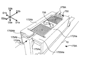
- FIG. 6 is a diagram illustrating a board holder from which the passive circuit board has been removed according to the first embodiment of the present invention.
- FIG. 7 is a diagram illustrating a substrate holder to which a passive circuit board according to the first embodiment of the present invention is attached.
- FIG. 8 is a view of the substrate holder from which the fixing member has been removed according to the first embodiment of the present invention as viewed from below.
- FIG. 9 is a diagram illustrating a cross section (cutting line Ac1-Ac2) of the substrate holder according to the first embodiment of the present invention.
- FIG. 10 is a diagram illustrating a cross section (cutting line Bc1-Bc2) of the substrate holder according to the first embodiment of the present invention.
- FIG. 11 is a diagram illustrating a cross section (cutting lines Bc1-Bc2) of a substrate holder to which a fixing member is attached according to the first embodiment of the present invention.
- a key 10 is arranged in the upward direction D3a of the substrate holder 170 shown in each figure.
- the board holder 170 is connected to the surface of the key 10 in the downward direction D3b.
- the key 10 and the board holder 170 are fixed by a fixing member 190.
- the fixing member 190 is made of metal.
- the fixing member 190 is not limited to metal, and may be formed of other materials such as resin. This also applies to the following other embodiments and modifications.
- the substrate holder 170 is made of resin in this example and is manufactured by injection molding.
- the substrate holder 170 has a substantially rectangular parallelepiped shape with a part opened. Part of the opening is due to restrictions in the production of injection molding and also to realize the functions of the configurations described below.
- the method of manufacturing the substrate holder 170 is not limited to injection molding, and may be manufactured by other methods such as cutting. This also applies to the following other embodiments and modifications.
- a plate-shaped bottom surface portion 179 is arranged on the upward D3a (key 10 side) of the substrate holder 170.
- a groove portion 1795c is arranged in the central portion of the bottom surface portion 179.
- the groove portion 1795c is a portion of the bottom surface portion 179 that is thinned along the front-rear direction D2.
- Through holes 1795a and 1795b penetrating the bottom surface portion 179 are arranged at both ends of the groove portion 1795c in the front-rear direction D2. As shown in FIGS.
- the fixing member 190 includes key-embedded portions 190a and 190b bent in the same direction and substantially vertically at both ends in the longitudinal direction of the plate-shaped member 190c having a longitudinal length and the plate-shaped member 190c. Including.
- the plate-shaped member 190c is arranged along the groove portion 1795c, and the key embedding portions 190a and 190b pass through the through holes 1795a and 1795b, respectively, are embedded in the key 10, and are fixed to the key 10.
- the key 10 and the substrate holder 170 are fixed by sandwiching the thinned portion of the bottom surface portion 179 in the groove portion 1795c between the plate-shaped member 190c and the key 10. By fixing the positional relationship between the key 10 and the board holder 170, the board holder 170 moves integrally with the key 10.
- a raised portion 177a is arranged via an elastic portion 1775a.
- the elastic portion 1775a functions as an elastic body by being cantilevered by the bottom surface portion 179.
- the raised portion 177a is raised in the downward direction D3b with respect to the bottom surface portion 179.
- the raised portion 177a can be moved in the vertical direction D3 by elastically deforming the elastic portion 1775a.
- a raised portion 177b is arranged on the bottom surface portion 179 in the right direction D1b via an elastic portion 1775b.
- the elastic portion 1775b functions as an elastic body by being cantilevered by the bottom surface portion 179.
- the raised portion 177b is raised in the downward direction D3b with respect to the bottom surface portion 179.
- the raised portion 177b can be moved in the vertical direction D3 by elastically deforming the elastic portion 1775b.
- the raised portion 177a and the raised portion 177b are arranged so as to sandwich the groove portion 1795c.
- a side surface portion 171a extending toward the downward direction D3b is arranged.
- a side surface portion 171b extending toward the downward direction D3b is arranged.
- a side surface 178 extending toward the downward D3b is arranged.
- the side surface portions 171a, 171b, and 178 are plate-shaped members including a portion substantially perpendicular to the bottom surface portion 179.
- Lid portions 172a and 173a extending toward the right direction D1b are arranged at both ends of the side surface portion 171a in the downward direction D3b and in the front-rear direction, respectively.
- the lid portions 172a and 173a are plate-shaped members substantially parallel to the bottom surface portion 179.
- the linear protruding portion 1725a is arranged on the surface on the upward D3a side (the surface on the inner side of the substrate holder 170).
- the linear protrusion 1725a is arranged along the front-rear direction D2.
- the linear protruding portion 1735a is arranged on the surface on the upward D3a side (the surface on the inner side of the substrate holder 170).
- the linear protrusion 1735a is arranged along the front-rear direction D2.
- Lid portions 172b and 173b extending toward the left direction D1a are arranged at both ends of the side surface portion 171b in the downward direction D3b and in the front-rear direction, respectively.
- the lid portions 172b and 173b are plate-shaped members substantially parallel to the bottom surface portion 179.
- the linear protruding portion 1725b is arranged on the surface on the upward D3a side (the surface on the inner side of the substrate holder 170).
- the linear protrusion 1725b is arranged along the front-rear direction D2.
- the linear protruding portion 1735b is arranged on the surface on the upward D3a side (the surface on the inner side of the substrate holder 170).
- the linear protrusion 1735b is arranged along the front-rear direction D2.
- a raised portion 175 is arranged at the end of the bottom surface portion 179 in the front direction D2a via an elastic portion 1755.
- the elastic portion 1755 functions as an elastic body by being cantileveredly supported by the bottom surface portion 179.
- the raised portion 175 is raised in the downward direction D3b with respect to the bottom surface portion 179, and the length in the front-rear direction D2 becomes shorter toward the downward D3b.
- the raised portion 175 includes a portion that is substantially perpendicular to the bottom surface portion 179 on the surface on the rear D2b side (the surface on the inner side of the substrate holder 170).
- the passive circuit board 750 When the passive circuit board 750 is inserted into the board holder 170 through the opening 170a, the passive circuit board 750 moves the raised portions 177a and 177b upward to D3a, and finally the passive circuit board 750 is on the side surface. Contact part 178. In this state, the raised portion 175 returns to its original position. In this process, the capacitor 756 arranged on the passive circuit board 750 passes between the lid portion 172a and the lid portion 172b. Therefore, even if the capacitor 756 has a shape protruding from the surface 750a, it does not hinder the insertion of the passive circuit board 750. The raised portion 175 does not have to completely return to its original position because it is in contact with the end face or the edge of the passive circuit board 750.
- the elastic portion 1755 may continue to receive the force F in the upward direction D3a by the passive circuit board 750, but the position of the raised portion 175 is at least to the extent that the passive circuit board 750 cannot pass through the opening 170a.
- the passive circuit board 750 is housed in the board holder 170, and its side surface portion 171a and side surface portion 171b determine the position of D1 in the left-right direction, and the side surface portion 178 and the raised portion 175 determine the position of D2 in the front-rear direction. Be done.
- the raised portions 177a and 177b moved to the passive circuit board 750 try to return to their original positions by the restoring forces of the elastic portions 1775a and 1775b, respectively. Therefore, the raised portions 177a and 177b exert a force on the passive circuit board 750 in the downward direction D3b, and the passive circuit board 750 is pressed against the linear protrusions 1725a, 1725b, 1735a, and 1735b. Thereby, the position of the passive circuit board 750 in the vertical direction D3 is determined. In this way, the passive circuit board 750 is held in the board holder 170.
- the passive circuit board 750 Even if there is a certain allowable range in the position of the passive circuit board 750 in the left-right direction D1 and the front-rear direction D2, the passive circuit board 750 is sandwiched from the vertical direction D3 in the board holder 170. Therefore, the passive circuit board 750 hardly moves while being held inside the board holder 170.
- the key pressing amount measuring unit 70 can measure the pressing amount of the key 10 using the magnetic induction type sensor.
- the passive circuit board 750 needs to be provided for each key 10.
- the substrate holder 170 fixed to the key 10 can hold and release the passive circuit board 750 by elastically deforming the elastic portion 1755, that is, the passive circuit board 750 is attached and detached. Hold as possible. Therefore, the passive circuit board 750 can be easily attached to or detached from the substrate holder 170, and as a result, the manufacturing process of the keyboard device 1 can be facilitated and the maintainability can be improved.
- the key 10 and the substrate holder 170 have separate configurations, and the positional relationship is fixed to each other via the fixing member 190.
- the substrate holder 170A integrally formed with the key 10 will be described with reference to FIGS. 12 and 13.
- the key 10 and the substrate holder 170A are integrally formed by injection molding and are made of the same material.
- FIG. 12 is a diagram illustrating a board holder from which the passive circuit board has been removed according to the second embodiment of the present invention.
- FIG. 13 is a diagram illustrating a substrate holder to which a passive circuit board according to a second embodiment of the present invention is attached.
- the board holder 170A is continuously configured with the key 10 and includes a structure similar to that of the board holder 170. Since the side surface portions 171Aa and 171Ab and 178A and the lid portions 172Aa and 172Ab are similar to the corresponding configurations in the substrate holder 170, their description will be omitted.
- the configuration of the opening 170Aa is different from that of the opening 170a in the substrate holder 170.
- a raised portion 175Aa is arranged at an end portion of the side surface portion 171Aa in the front direction D2a and an end portion in the upward direction D3a via an elastic portion 1755Aa extending toward the right direction D1b.
- the elastic portion 1755Aa functions as an elastic body by being cantilevered by the side surface portion 171Aa.
- the raised portion 175Aa is raised in the upward direction D3a with respect to the elastic portion 1755Aa.
- the raised portion 175Aa includes a portion that is substantially perpendicular to the bottom surface portion 179A on the surface on the rear D2b side (the surface on the inner side of the substrate holder 170A).
- a raised portion 175Ab is arranged at an end portion of the side surface portion 171Ab in the front direction D2a and an end portion in the upward direction D3a via an elastic portion 1755Ab extending toward the left direction D1a.
- the elastic portion 1755Ab functions as an elastic body by being cantilevered by the side surface portion 171Ab.
- the raised portion 175Ab is raised in the upward direction D3a with respect to the elastic portion 1755Ab.
- the raised portion 175Ab includes a portion that is substantially perpendicular to the bottom surface portion 179A on the surface on the rear D2b side (the surface on the inner side of the substrate holder 170A).
- An opening 170Aa is formed in the front direction D2a of the substrate holder 170A.
- an opening 170Aa having a size capable of inserting the passive circuit board 750 into the substrate holder 170A is secured.
- the passive circuit board 750 As the passive circuit board 750 is inserted into the board holder 170A through the opening 170Aa, the passive circuit board 750 comes into contact with the side surface portion 178A.
- the raised portions 175Aa and 175Ab return to their original positions.
- the capacitor 756 arranged on the passive circuit board 750 passes between the raised portion 175Aa and the raised portion 175Ab.
- the raised portions 175Aa and 175Ab do not have to be completely returned to their original positions because they are in contact with the end faces or edge edges of the passive circuit board 750. That is, the elastic portions 1755Aa and 1755Ab may continue to be subjected to the force F in the upward direction D3a by the passive circuit board 750, but the raised portion 175Aa is at least to the extent that the passive circuit board 750 cannot pass through the opening 170Aa. The position of 175Ab returns.
- the passive circuit board 750 is positioned in the left-right direction D1 by the side surface portion 171Aa and the side surface portion 171Ab while being housed in the substrate holder 170A, and the position in the front-rear direction D2 by the side surface portion 178A and the raised portion 175Aa and 175Ab. Is determined, and the position of the vertical direction D3 is determined by the bottom surface portion 179A and the lid portions 172Aa and 172Ab. In this way, the passive circuit board 750 is held in the board holder 170A.
- the substrate holder 170A may be provided with a configuration corresponding to the elastic portion 1775a and the raised portion 177a.
- a force may be applied from the protruding portion to the passive circuit board 750 in the upward direction D3a.
- this configuration can be realized if the lid portions 172Aa and 172Ab are elastically deformed in the downward direction D3b while the passive circuit board 750 is held.
- the passive circuit board 750 can be removed from the board holder 170A by sliding the passive circuit board 750 toward the opening 170Aa while the raised portions 175Aa and 175Ab are moved downward to D3b. In this way, the substrate holder 170A holds the passive circuit board 750 detachably.
- the substrate holder 170A is integrally formed with the key 10, and particularly when the key 10 and the substrate holder 170A are integrally formed by injection molding, the substrate holder 170A is limited to a part of the shapes due to manufacturing restrictions.
- the fixing member 190 in the first embodiment may not be present.
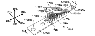
- the substrate holder 170B that holds the passive circuit board 750 detachably by opening and closing the lid will be described with reference to FIGS. 14 to 17.
- FIG. 14 is a diagram illustrating a board holder from which the passive circuit board has been removed according to the third embodiment of the present invention.
- FIG. 15 is a diagram illustrating a state in which a passive circuit board is arranged on a board holder according to a third embodiment of the present invention.
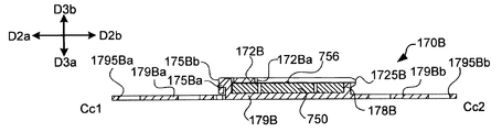
- FIG. 16 is a diagram illustrating a cross section (cutting line Cc1-Cc2) in a state where the passive circuit board is arranged on the substrate holder according to the third embodiment of the present invention.
- FIG. 17 is a diagram illustrating a cross section in a state where the passive circuit board is attached to the substrate holder by closing the lid portion 172B in FIG.
- the substrate holder 170B is made of resin in this example and is manufactured by injection molding.
- the substrate holder 170B has a substantially rectangular parallelepiped shape with a part opened, and has a lid structure whose one surface can be opened and closed.
- a plate-shaped bottom surface portion 179B is arranged on the upward D3a (key 10 side) of the board holder 170B.
- a bottom surface portion 179Ba is arranged in the front direction D2a of the bottom surface portion 179B, and a bottom surface portion 179Bb is arranged in the rear direction D2b.
- the bottom surface portion 179Ba includes a through hole 1795Ba, and the bottom surface portion 179Bb includes a through hole 1795Bb.
- These through holes 1795Ba and 1795Bb may be used for arranging a fixing member for fixing the substrate holder 170B to the key 10, and have the same functions as the through holes 1795a and 1795b in the first embodiment, for example. You may have.
- a side surface portion 171Ba is arranged at the end portion of the bottom surface portion 179B in the left direction D1a.
- a side surface portion 171Bb is arranged at an end portion of the bottom surface portion 179B in the right direction D1b.
- a side surface portion 174B is arranged at an end portion of the bottom surface portion 179B in the front direction D2a.
- a side surface portion 178B is arranged at an end portion of the bottom surface portion 179B in the rear direction D2b.
- the side surface portions 171Ba, 171Bb, 174B, and 178B are plate-shaped members including a portion substantially perpendicular to the bottom surface portion 179.
- a raised portion 175Ba is arranged on the side surface portion 174B.
- the raised portion 175Ba is raised in the forward direction D2a with respect to the side surface portion 174B.
- a plate-shaped lid portion 172B is arranged at an end portion of the side surface portion 178B in the downward direction D3b via a hinge portion 1725B.
- a notch 172Ba is formed in the lid portion 172B at a substantially central portion.
- An engaging portion 175Bb is arranged at an end portion of the lid portion 172B opposite to the hinge portion 1725B.
- the lid portion 172B can rotate about the hinge portion 1725B with respect to the bottom surface portion 179B. That is, the positional relationship between the lid portion 172B and the bottom surface portion 179B can be changed.
- the passive circuit board 750 is placed on the bottom surface portion 179B, and the lid portion 172B is moved in the closing direction C.
- the engaging portion 175Bb passes through the raised portion 175Ba and moves toward the upward D3a side of the raised portion 175Ba.
- the lid portion 172B is closed, so that the passive circuit board 750 is sandwiched between the two plate-shaped members, that is, the lid portion 172B and the bottom surface portion 179B (first state).
- the passive circuit board 750 is held by the board holder 170B.
- the capacitor 756 in the passive circuit board 750 is prevented from coming into contact with the lid portion 172B by the notch portion 172Ba.
- the passive circuit board 750 is housed in the board holder 170B, and the position of the lateral direction D1 is determined by the side surface portion 171Ba and the side surface portion 171Bb, and the position of the front-rear direction D2 is determined by the side surface portion 178B and the side surface portion 174B. The position of D3 in the vertical direction is determined by the bottom surface portion 179B and the lid portion 172B. In this way, the passive circuit board 750 is held in the board holder 170B.
- the substrate holder 170B may be provided with a configuration corresponding to the elastic portion 1775a and the raised portion 177a.
- An elastic body, a non-woven fabric, or the like is sandwiched between the lid portion 172B and the passive circuit board 750, and a force is applied from the lid portion 172B to the passive circuit board 750 in the upward direction D3a to cause the substrate holder 170B to move.
- the passive circuit board 750 may be held more strongly.
- the lid portion 172B When the lid portion 172B is opened while the engaging portion 175Bb receives the force F and the lid portion 172B and the bottom surface portion 179B are separated (second state), the holding of the passive circuit board 750 is released. In this way, the substrate holder 170B holds the passive circuit board 750 detachably.
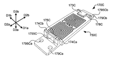
- the substrate holder 170C that holds the passive circuit board 750 detachably by snap-fit will be described with reference to FIGS. 18 to 21.
- FIG. 18 is a diagram illustrating a board holder from which the passive circuit board has been removed according to the fourth embodiment of the present invention.
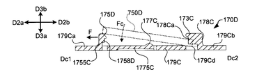
- FIG. 19 is a diagram illustrating a cross section (cutting line Dc1-Dc2) of the substrate holder according to the fourth embodiment of the present invention.
- FIG. 20 is a diagram illustrating a passive circuit board according to a fourth embodiment of the present invention.
- FIG. 21 is a diagram illustrating a substrate holder to which a passive circuit board according to a fourth embodiment of the present invention is attached.
- the substrate holder 170C is made of resin in this example and is manufactured by injection molding.
- a plate-shaped bottom surface portion 179C is arranged on the upward D3a (key 10 side) of the board holder 170C.
- the bottom surface portion 179Ca is arranged in the front direction D2a of the bottom surface portion 179C, and the bottom surface portion 179Cb is arranged in the rear direction D2b.
- the bottom surface portion 179Ca has a through hole 1795Ca, and the bottom surface portion 179Cb has a through hole 1795Cb.
- These through holes 1795Ca and 1795Cb may be used for arranging a fixing member for fixing the substrate holder 170C to the key 10, and have the same functions as the through holes 1795a and 1795b in the first embodiment, for example. You may have.
- a raised portion 177C is arranged at a substantially central portion of the bottom surface portion 179C via an elastic portion 1775C.
- the elastic portion 1775C functions as an elastic body by being cantilevered by the bottom surface portion 179C.
- the raised portion 177C is raised in the downward direction D3b with respect to the bottom surface portion 179C.
- a groove portion 179Cc and 179Cd thinned at the end portion in the rear direction D3b are arranged.
- a side surface portion 174Ca extending toward the downward direction D3b, an elastic portion 1755C, and a side surface portion 174Cb are arranged in order along the left-right direction D1.
- the side surface portion 174Ca, 174Cb, and the elastic portion 1755C are plate-shaped members including a portion substantially perpendicular to the bottom surface portion 179C.
- a raised portion 175C is arranged at the end of the downward D3b of the elastic portion 1755C.
- the elastic portion 1755C functions as an elastic body by being cantilevered by the bottom surface portion 179C.
- the raised portion 175C is raised in the rear direction D2b with respect to the elastic portion 1755C.
- the raised portion 175 includes a portion that is substantially parallel to the bottom surface portion 179 on the surface on the upward D1a side.
- a side surface 178C extending toward the downward D3b is arranged.
- a guide portion 178Ca that projects toward the front direction D2a is arranged on the side surface portion 178C.
- the guide portion 178Ca is a plate-shaped member that extends in the vertical direction D3 and the front-rear direction D2.
- a lid portion 173C extending toward the front direction D2a is arranged.
- the lid portion 173C is a plate-shaped member substantially parallel to the bottom surface portion 179C.
- a notch portion 7508C is formed in the passive circuit board 750C.
- the cutout portion 7508C and the guide portion 178Ca have corresponding shapes.
- the passive circuit board 750C is attached to the board holder 170C, first, as shown in FIG. 19, the passive circuit board 750C is arranged in the board holder 170C so that the guide portion 178Ca is inserted into the notch portion 7508C. After that, when a force F is applied to the forward direction D2a with respect to the raised portion 175C, the elastic portion 1755C is elastically deformed, so that the raised portion 175C moves in the forward direction D2a. Then, by pushing the passive circuit board 750C toward the bottom surface portion 179C side by the force Fc, the passive circuit board 750C is fitted into the board holder 170C.
- the passive circuit board 750C is positioned in the left-right direction D1 by fitting the guide portion 178Ca of the board holder 170C and the notch portion 7508C (particularly, the contact between the guide portion 178Ca and the notch portion 7508C in the left-right direction D1).
- the position of D2 in the front-rear direction is determined by the guide portion 178Ca (or the side surface portion 178C) and the side surface portions 174Ca and 174Cb.
- the raised portions 177C moved upward to the D3a side by the passive circuit board 750C each try to return to their original positions by the restoring force of the elastic portions 1775C.
- the raised portion 177C applies a force downward to D3b with respect to the passive circuit board 750C, and the passive circuit board 750C is pressed against the lid portion 173C and the raised portion 177C. Thereby, the position of the passive circuit board 750C in the vertical direction D3 is determined. In this way, the passive circuit board 750C is held by the board holder 170C.
- a force F is applied to elastically deform the elastic portion 1755C and move the raised portion 175C in the forward direction D2a to move the passive circuit board by the substrate holder 170C.
- the holding of 750C is released. In this way, the holding of the passive circuit board 750C is released in the state where the elastic portion 1755C is elastically deformed as compared with the state when the passive circuit board 750C is held by the board holder 170C.
- the passive circuit board 750D in which the two notches 7505D and 7508D are formed and the substrate holder 170D holding the passive circuit board 750D will be described with reference to FIGS. 22 and 23.
- FIG. 22 is a diagram illustrating a passive circuit board according to a fifth embodiment of the present invention.
- the cutout portion 7508D in the passive circuit board 750D is the same as the cutout portion 7508C in the fourth embodiment.
- the notch portion 7505D is formed at a position facing the notch portion 7508D.
- FIG. 23 is a diagram illustrating a cross section (corresponding to FIG. 19) of the substrate holder according to the fifth embodiment of the present invention.
- the substrate holder 170D has almost the same configuration as the substrate holder 170C, but the side surface portions 174Ca and 174Cb of the substrate holder 170C do not exist, and the substrate holder 170D protrudes from the elastic portion 1755C on the bottom surface portion 179C side of the raised portion 175C.
- a guide portion 1758D is arranged.
- the same configuration is designated by the same reference numerals as the substrate holder 170C in the fourth embodiment.
- the guide portion 1758D has a shape corresponding to the notch portion 7505D, and the guide portion 1758D is fitted into the notch portion 7505D in a state where the passive circuit board 750D is held by the substrate holder 170D.
- the passive circuit board 750D in a state where the passive circuit board 750D is held by the board holder 170D, the passive circuit board 750D is fitted with the guide portion 178Ca and the notch portion 7508D (particularly, the guide portion 178Ca and the notch portion 7508D are fitted together.
- the position of the left-right direction D1 is determined by the contact in the left-right direction D1) and the fitting of the guide portion 1758D and the notch portion 7505D (particularly the contact between the guide portion 1758D and the notch portion 7505D in the left-right direction D1).
- the position of D2 in the front-rear direction is determined by the 178Ca (or the side surface portion 178C) and the guide portion 1758D (or the elastic portion 1755C).
- the position of the passive circuit board 750D in the vertical direction D3 is determined in the same manner as in the fourth embodiment. In this way, the passive circuit board 750D is held by the board holder 170D.
- a force F is applied to elastically deform the elastic portion 1755D and move the raised portion 175D in the forward direction D2a to move the passive circuit board by the substrate holder 170D.
- the holding of the 750D is released.
- the holding of the passive circuit board 750D is released in the state where the elastic portion 1755C is elastically deformed as compared with the state when the passive circuit board 750D is held by the board holder 170D.
- the keyboard device 1E including the substrate holder 170E fixed to the member interlocking with the key 10 instead of the key 10 will be described with reference to FIGS. 24 to 26.
- the key connecting portion 301 of the load portion 30 is illustrated.
- FIG. 24 is a diagram illustrating an internal structure (at the time of key release) of the keyboard device according to the sixth embodiment of the present invention.
- FIG. 25 is a diagram illustrating an internal structure (when a white key is pressed) of a keyboard device according to a sixth embodiment of the present invention.
- the substrate holder 170E is fixed to the lower surface side of the key connection portion 301. Therefore, the board holding portion 207E on which the active circuit board 700 is arranged is arranged is arranged below the key connecting portion 301.
- the load portion 30 rotates in conjunction with the rotation of the key 10 to move the weight portion 305 upward, and the upper stopper 353 Collision with and further movement is restricted.
- the key connection portion 301 moves downward, and the active circuit board 700 and the passive circuit board 750D come close to each other.
- the substrate holder 170E is arranged near the center of rotation as a position where the amount of movement is reduced during rotation, but the substrate holder 170E is arranged at a position away from the center of rotation depending on the application. It may be done.
- the difference between the time when the key is released and the time when the key is pressed is larger than that in the first embodiment in which the passive circuit board 750D is attached to the key 10. Even if the change in the angle is large, the amount of magnetic flux passing through the passive coil 751 changes. Therefore, there is no problem even if the positional relationship between the passive coil 751 and the active coil 701 is as in the sixth embodiment.
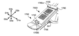
- FIG. 26 is a diagram illustrating a substrate holder to which a passive circuit board according to a sixth embodiment of the present invention is attached.
- the substrate holder 170E the configuration corresponding to the substrate holder 170D in the fifth embodiment is applied as it is.
- the substrate holder 170E and the key connection portion 301 are integrally formed by injection molding and are made of the same material. Since the substrate holder 170E and the substrate holder 170D have the same configuration, the passive circuit board 750D shown in the fifth embodiment is attached to the substrate holder 170E.
- the bottom surface portion 179E, side surface portion 178E, lid portion 173E, guide portion 178Ea, elastic portion 1755E, and raised portion 175E of the substrate holder 170E are the bottom surface portion 179C, side surface portion 178C, lid portion 173C, guide portion 178Ca, and elastic portion of the substrate holder 170D. Corresponds to the portion 1755C and the raised portion 175D, respectively.
- the keyboard device 1F including the board holder 170F attached to other than the key 10 and the load unit 30 will be described with reference to FIGS. 27 to 31.
- FIG. 27 is a diagram illustrating an internal structure (at the time of key release) of the keyboard device according to the seventh embodiment of the present invention.
- FIG. 28 is a diagram illustrating an internal structure (when a white key is pressed) of a keyboard device according to a seventh embodiment of the present invention.
- the substrate holder 170F is arranged in the substrate holding portion 207E below the key connecting portion 301 so as to cover the active circuit board 700.
- the substrate holder 170F is a dome-shaped structure formed of an elastic body such as rubber, and has a mechanism for holding the passive circuit board 750F in a part thereof.
- the load portion 30 rotates in conjunction with the rotation of the key 10 to move the weight portion 305 upward, and the upper stopper 353 Collision with and further movement is restricted.
- the key connecting portion 301 comes into contact with the board holder 170F while the key connecting portion 301 is moving downward.
- the key connection portion 301 deforms the board holder 170F by moving further downward.
- the passive circuit board 750F held by the board holder 170F approaches the active circuit board 700.
- the substrate holder 170F returns to its original position and returns to the state shown in FIG. 27, the substrate holder 170F returns to its original shape due to its own restoring force, and the passive circuit board 750F separates from the active circuit board 700.
- the shape of the substrate holder 170F changes with the movement of the key 10 in a part of the key pressing range. Therefore, the substrate holder 170F can be said to be a member linked to the key 10. Subsequently, the substrate holder 170F will be described.
- FIG. 29 is a diagram illustrating a board holder to which a passive circuit board according to a seventh embodiment of the present invention is attached.
- FIG. 30 is a diagram illustrating the inside of a substrate holder to which a passive circuit board is attached according to the seventh embodiment of the present invention (a view of the substrate holder viewed from below).
- FIG. 31 is a diagram illustrating a cross section (cutting line Ec1-Ec2) of the substrate holder according to the seventh embodiment of the present invention.
- the substrate holder 170F includes a base portion 170Fz and a portion forming a dome shape extending upward D3a from the base portion 170Fz.
- the portion forming the dome shape includes a lower side surface portion 170Fy, an upper side surface portion 170Fx, and an upper surface portion 170Ft. Lids 172Fa and 172Fb projecting to the inner surface side are arranged on the upper side surface portion 170Fx.
- a protruding portion 1705Fz projecting downward D3b is arranged corresponding to each of the four corner portions.
- the protruding portion 1705Fz is fitted into the hole portion TH provided in the active circuit board 700. Thereby, the position of the board holder 170F (passive circuit board 750F) with respect to the active circuit board 700 is determined.
- the passive circuit board 750F has an outer circumference along the shape of the upper side surface portion 170Fx, and unlike the passive circuit board 750 in the above-described embodiment, a portion corresponding to a rectangular corner portion is formed in an arc shape. ..
- the passive circuit board 750F is held by the board holder 170F by being sandwiched between the upper surface portion 170Ft and the lid portions 172Fa and 172Fb. Since the passive circuit board 750F is a rigid structure, the substrate holder 170F retains its shape due to the influence of the passive circuit board 750F even if it is an elastic body on the upper surface 170Ft side of the lids 172Fa and 172Fb. Almost no deformation. Therefore, when the key connection portion 301 deforms the substrate holder 170F, the lower side surface portion 170Fy is mainly deformed, and the upper surface portion 170Ft approaches the active circuit board 700.
- the substrate holder 170F When attaching or detaching the passive circuit board 750F to or from the substrate holder 170F, the substrate holder 170F is deformed by applying a force F so as to expand the lids 172Fa and 172Fb to the outside, until the passive circuit board 750F can pass through.
- the opening 170 Fa can be expanded. That is, the passive circuit board 750F can be attached to or detached from the substrate holder 170F by passing the passive circuit board 750F through the gap between the lid portion 172Fa and the lid portion 172Fb.
- the board holder 170F is provided corresponding to each key 10.
- the base portion 170Fz of the adjacent substrate holder 170F may be connected.
- the substrate holder 170F as in the seventh embodiment is formed by injection molding
- the substrate holder 170G formed by inserting the passive circuit board 750F into the injection molding die is shown in FIGS. 32 and 33. Will be described using.
- FIG. 32 is a diagram illustrating the inside of the substrate holder to which the passive circuit board according to the eighth embodiment of the present invention is attached.
- FIG. 33 is a diagram illustrating a cross section (cutting line Fc1-Fc2) of the substrate holder according to the eighth embodiment of the present invention.
- the substrate holder 170G is an elastic body formed by injection molding, like the substrate holder 170F. In this example, since the passive circuit board 750F is incorporated into the elastic body during injection molding, the substrate holder 170G cannot attach or detach the passive circuit board 750F.
- the upper surface 170Gt, upper side surface 170Gx, lower side surface 170Gy, base 170Gz and protrusion 1705Gz of the board holder 170G are the upper surface 170Ft, upper side surface 170Fx, lower side surface 170Fy, base 170Fz and protrusion of the board holder 170F. Corresponds to each part 1705Fz.
- the configuration of the lid portion 172G arranged on the inner surface side of the upper side surface portion 170Gx is different from that of the lid portion 172F of the substrate holder 170F.
- a through hole 172Gp is formed in the lid portion 172G.
- the through hole 172Gp does not necessarily have to be formed, but in this example, the capacitor 756 of the passive circuit board 750F is exposed.
- the resin may stress the capacitor 756 due to the expansion and contraction of the material.
- the influence of such stress can be avoided.
- such a through hole 172Gp be as small as possible for holding the passive circuit board 750F.
- a through hole having a shape corresponding to the portion where the pin is arranged remains.
- all the through holes, including the above-mentioned through hole 172 Gp have a size that the passive circuit board 750F cannot pass through.
- the substrate holder 170G cannot be configured so that the passive circuit board 750F can be detached, but it is efficient to replace the entire substrate holder 170G. It is effective in the case of.
- FIG. 34 is a diagram illustrating a substrate holder to which a passive circuit board according to a ninth embodiment of the present invention is attached.
- the substrate holder 170H is arranged on the lower surface side of the key connection portion 301.
- the substrate holder 170H and the key connection portion 301 are integrally formed by injection molding.
- the passive circuit board 750 is also put in a mold and formed together with the board holder 170H. Similar to the substrate holder 170G of the eighth embodiment, a through hole 1705Ha is formed in the lower surface portion 170Ha of the substrate holder 170H.
- the capacitor 756 of the passive circuit board 750 is exposed from the substrate holder 170H by the through hole 1705Ha.
- through holes 1705Hb and 1705Hc are formed in the side surface portions 170Hb and 170Hc.
- the through holes 1705Hb and 1705Hc are holes formed because a pin for supporting the passive circuit board 750 was arranged during injection molding.
- Magnetically induced sensors can also be used in acoustic pianos.
- the grand piano 1J using the substrate holder 170 will be described with reference to FIGS. 35 to 37.
- FIG. 35 is a diagram illustrating an internal structure (at the time of key release) of the keyboard device according to the tenth embodiment of the present invention.
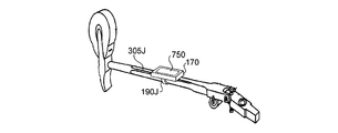
- FIG. 36 is a diagram illustrating a mounting position of the substrate holder according to the tenth embodiment of the present invention.
- the substrate holder 170 is attached to the hammer shank 305J of the grand piano 1J by a fixing member 190J.
- the fixing member 190J has a shape that surrounds the axis of the hammer shank 305J.
- the outer edge is not a circle in the cross section (cross section perpendicular to the longitudinal direction) as in the hammer shank 305J shown in FIG.
- a fixing member 190J having an inner surface shape matching the outer edge shape can be used. It is also possible to avoid rotation around the axis.
- the fixing member 190J may be adhered to the hammer shank 305J.
- the fixing member 190 described in the first embodiment may be inserted into the hammer shank 305J to fix the substrate holder 170 to the hammer shank 305J.
- the active circuit board 700 is arranged on the board holding portion 207J fixed to the frame 20J.
- the active circuit board 700 is arranged on the lower surface side of the substrate holding portion 207J, but if the substrate holding portion 207J is a resin structure, it is arranged on the upper surface side of the substrate holding portion 207J. May be good.
- the substrate holder 170 may be attached to another position of the hammer shank 305J.
- FIG. 37 is a diagram illustrating another example of the mounting position of the substrate holder according to the tenth embodiment of the present invention.
- the substrate holder 170 is attached to the surface of the hammer shank 305J on the opposite side of the portion to which the hammer roller 309J is attached.
- This surface is a portion of the hammer shank 305J that has a relatively wide range of planes. Therefore, it is easy to arrange the substrate holder 170.
- the board holder 170 may be attached to the jack 307J or the key 10J in addition to the hammer shank 305J.
- the active circuit board 700 may be arranged on the frame 20J. At this time, the active circuit board 700 may be arranged upright so that the normal of the surface thereof faces the jack 307J.
- the active circuit board 700 may be arranged on the shelf board 50J.
- FIG. 38 is a diagram illustrating an internal structure (at the time of key release) of the keyboard device according to the eleventh embodiment of the present invention.
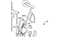
- FIG. 39 is a diagram illustrating a mounting position of the substrate holder according to the eleventh embodiment of the present invention.
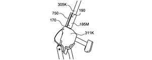
- the substrate holder 170 is attached to the hammer shank 305K of the upright piano 1K by a fixing member 190K.
- the fixing member 190K has a shape that surrounds the axis of the hammer shank 305K.
- the hammer shank 305K has a cylindrical shape.
- the fixing member 190J may be adhered to the hammer shank 305J.
- the fixing member 190 described in the first embodiment may be inserted into the bat 311K and fixed in the area CA.
- the active circuit board 700 is arranged in a board holding portion 207K fixed to a frame (not shown). Further, the substrate holder 170 may be attached to the hammer shank 305K in another form.
- FIG. 40 is a diagram illustrating an example in which the substrate holder according to the eleventh embodiment of the present invention is attached in another form.
- the fixing member 190 described in the first embodiment is inserted into the hammer shank 305K, and the substrate holder 170 is fixed to the hammer shank 305K.
- an auxiliary member 195M for filling the space between the substrate holder 170 and the hammer shank 305K may be arranged.
- FIGS. 41 and 42 are shown for the substrate holder 170N which holds the passive circuit board 750N by another configuration with respect to the substrate holder 170E integrally formed with the key connection portion 301 as in the sixth embodiment. It will be described using.
- FIG. 41 is a diagram illustrating a substrate holder to which a passive circuit board according to a twelfth embodiment of the present invention is attached.
- FIG. 42 is a diagram illustrating a cross section (cutting line Gc1-Gc2) of the substrate holder according to the twelfth embodiment of the present invention.
- FIG. 41 is a view when the substrate holder 170N is viewed from below.
- the board holder 170N is arranged below the key connection portion 301.
- the bottom surface portion 179N, side surface portion 178N, lid portion 173N, and guide portion 178Na of the substrate holder 170N correspond to the bottom surface portion 179E, side surface portion 178E, lid portion 173E, and guide portion 178Ea of the substrate holder 170E shown in FIG. 26, respectively.
- the notch portion 7508N in the passive circuit board 750N attached to the substrate holder 170N corresponds to the notch portion 7508D in the passive circuit board 750D shown in FIG. 22.
- the substrate holder 170N includes a male screw 175N and a female screw 1795N instead of the substrate holder 170E having an elastic portion 1755E and a raised portion 175E.
- the female screw 1795N is formed on the bottom surface portion 179N.
- the passive circuit board 750N includes an opening 7505N instead of the passive circuit board 750D having a notch 7505D.
- the passive circuit board 750N is sandwiched between the head portion of the male screw 175N and the bottom surface portion 179N, and the position of the vertical direction D3 is determined.
- the position is determined, and the position of the left-right direction D1 is determined by fitting the guide portion 178Na and the notch portion 7508N (particularly, the contact between the guide portion 178Na and the notch portion 7508N in the left-right direction D1).
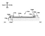
- the substrate holder 170P that holds the passive circuit board 750P by another configuration with respect to the substrate holder 170N in the twelfth embodiment will be described with reference to FIGS. 43 and 44.
- FIG. 43 is a diagram illustrating a substrate holder to which the passive circuit board according to the thirteenth embodiment of the present invention is attached.
- FIG. 44 is a diagram illustrating a cross section (cutting line Hc1-Hc2) of the substrate holder according to the thirteenth embodiment of the present invention.
- the board holder 170P is arranged below the key connection portion 301.
- the male screw 175Pb and the female screw 1795Pb in the board holder 170P correspond to the male screw 175N and the female screw 1795N in the board holder 170N, respectively.
- the opening 7505Pb in the passive circuit board 750P attached to the board holder 170P corresponds to the opening 7505N in the passive circuit board 750N.
- the board holder 170P includes a male screw 175 Pa and a female screw 1795 Pa instead of the board holder 170 N having a side surface portion 178 N, a lid portion 173 N, and a guide portion 178 Na.
- the passive circuit board 750P includes an opening 7505Pa instead of the passive circuit board 750N having a notch 7508N.
- the substrate holder 170P includes protrusions 1755Pa and 1755Pb protruding downward from the bottom surface 179P.
- the passive circuit board 750P includes openings 7555Pa and 7555Pb into which protrusions 1755Pa and 1755Pb are inserted.
- the opening 7505Pa has a configuration in which a part of the opening reaches the end of the passive circuit board 750P and a part of the opening 7505Pa is not surrounded by the passive circuit board 750P, but the whole is surrounded.
- the opening 7505Pa may be formed in the.
- the size of the unenclosed part is smaller than the diameter of the shaft of the male screw 175Pa, that is, from the inside to the outside of the opening 7505Pa. It is preferable that the shaft of the male screw 175 Pa cannot pass through.
- the male screw 175Pa and 175Pb penetrate the openings 7505Pa and 7505Pb, respectively, and the heads of the male screw 175Pa and 175Pb, respectively.
- the portion contacts the surface 750Pb of the passive circuit board 750P.
- the protrusions 1755Pa and 1755Pb penetrate the openings 7555Pa and 7555Pb, respectively.
- the protrusion 1755Pa does not have to penetrate the opening 7555Pa as long as it penetrates the inside of the opening 7555Pa. The same applies to the protrusion 1755Pb.
- the passive circuit board 750P is sandwiched between the head portion and the bottom surface portion 179P of the male screw 175Pa and 175Pb, and the position of the vertical direction D3 is determined.
- the position of direction D2 is determined.
- the passive circuit board 750P may be positioned in the left-right direction D1 and the front-rear direction D2 by the shaft portion of the male screw 175Pa and the shaft portion of the 175Pb.
- the positions of the left-right direction D1 and the front-rear direction D2 may be determined by two configurations. In order to determine the position of the vertical direction D3, at least one of the male screws 175Pa and 175Pb may be present.
- a recess 1756P is further formed on the bottom surface portion 179P.
- the recess 1756P is formed at a position corresponding to the capacitor 756P of the passive circuit board 750P. Therefore, even if the passive circuit board 750P is arranged so that the capacitor 756P faces the bottom surface portion 179P side, the portion of the capacitor 756P can be accommodated in the region of the recess 1756P. This makes it possible to prevent physical interference from other structures with respect to the capacitor 756P.
- the passive coil 751 is provided on the passive circuit board 750, a metal plate may be provided instead of the passive coil 751. Even with this configuration, it is possible to modulate the output signal of the active circuit 770 by the eddy current generated in the metal plate in the same manner as the passive coil 751. That is, in the passive circuit board 750, a conductor capable of absorbing energy via a magnetic field, such as a metal plate, may be arranged instead of the coil.
- the active coil 701 is arranged on the frame 20 side, and the passive coil 751 is held by the substrate holder 170 and arranged on the key 10 side. Since the passive coil 751 does not require power supply or the like, it is easy in design to be provided in a structure having a movable portion, but it can be realized even if the passive coil 751 is arranged in the opposite relationship. That is, the active coil 701 may be arranged on the key 10 side, and the passive coil 751 may be arranged on the frame 20 side. At this time, a configuration for supplying power or the like may be arranged in the substrate holder 170.
- the distance between the active coil 701 and the passive coil 751 was closer when the key was pressed than when the key was released, but it may be closer when the key is released.
- This configuration may be realized via a member interlocked with the key 10, or the active circuit board 700 may be arranged on the upper surface side of the key 10.
- One set of the active circuit 770 and the passive circuit board 750 is provided for each key 10, but a plurality of sets may be provided for each key 10.
- a sensor that measures the amount of key 10 pressed as in the first embodiment and a sensor that measures the amount of movement of a member linked to the key 10 as in the sixth embodiment can be used to measure the amount of movement of a plurality of members. May be able to be measured.
- the key 10 may be provided with a plurality of sensors. In this case, the measurable range of the pressing amount may be different for each sensor. Further, information on the sounding timing and the key pressing speed may be generated based on the sensor provided on the load unit 30, and information on the muffling timing may be generated based on the sensor provided on the key 10.
- the coil shape of the active coil 701 can take various forms other than the various forms described above. Further, the active coil 701 may be realized by using a plurality of coils. The same applies to the passive coil 751. Various forms can be adopted for the active coil 701 and the passive coil 751 as long as the active coil 701 can form a magnetic field and the passive coil 751 can cause antiresonance in the active circuit 770 via the magnetic field. ..
- the active circuit board 700 is arranged on the frame 20 (board holding portion 207) that is not linked to the key 10, but the positional relationship between the active circuit board 700 and the passive circuit board 750 when the key is released and when the key is pressed. If changes, the active circuit board 700 may be arranged on the member interlocking with the key 10.
- the fixing member 190 for fixing the board holder 170 to the key 10 or a member interlocking with the key 10 may be a combination of screws, bolts and nuts, double-sided tape, adhesive, tacker, nailer, or hot bond.
- the material and form can be various, but in order to reduce the influence on the magnetic field, it is desirable that the material has a relative magnetic permeability close to 1 or an insulator material such as a resin.
- the substrate holder 170 and the key 10 may be fixed by press-fitting with a dowel or the like.
- the passive circuit board 750 may be directly fixed to the key 10 or a member interlocking with the key 10 with a fixing member without using the board holder 170.
- the fixing member may be a double-sided tape, an adhesive, a tacker, a nailer, or a hot bond, and may be made of various materials and forms, but is transparent in order to reduce the influence on the magnetic field. It is desirable that the material has a magnetic coefficient close to 1 or an insulator material such as a resin.
- the passive circuit board 750 and the active circuit board 700 have a positional relationship in which both surfaces are substantially opposed to each other, and the coils provided on both surfaces may approach the D3 in the vertical direction by operating the key 10. The distance between them changes as they move away from each other.
- the key press amount measuring unit 70 functions as a distance sensor by outputting a signal corresponding to this distance.
- the key pressing amount measuring unit 70 can function as a distance sensor in the same manner. For example, it is assumed that both the surfaces of the passive circuit board 75 and the active circuit board 700 are arranged so as to have a normal line along the left-right direction D1.
- the key pressing amount measuring unit 70 can function as a distance sensor.
- the electronic keyboard instrument has been described as having a speaker 60 and a sound source unit 80, or an acoustic piano such as a grand piano or an upright piano having a sounding mechanism such as a string.
- the speaker 60 and the sound source unit 80 may be omitted from the electronic keyboard instrument.
- the key press amount measuring unit 70 is used to record the performance content of the keyboard or output the performance signal to the outside.
- the present invention is also specified as a device (performance operation device) that controls sound generation by outputting an operation signal according to a performance operation to the sound source unit 80 or a sound generation mechanism.
- the performance operation device includes a musical instrument (keyboard device 1) having a sound source unit 80 to output a sound signal, and a musical instrument having a sounding mechanism for sounding.
- a device that does not output a sound signal for example, a MIDI controller
- a device that does not sound by itself for example, a pedal mechanism
- the keys and pedals are identified as controls for playing operations.
- the performance operation device controls the generation of sound and the mode of generation of the sound according to the operation of the operator by the performer (operator) with his / her hand or foot, or outputs a sound signal. Includes a device to play.
- the structure When applied to a pedal mechanism, the structure is such that the board holder 170 is fixed to the pedal as an operator, and the passive circuit board 750 held by the board holder 170 and the support portion that operably supports the pedal are provided.
- the active circuit board 700 may face each other, and the operation may be detected by changing the distance (positional relationship) between the passive circuit board 750 and the active circuit board 700 by operating the pedal.
- 1,1E, 1F ... keyboard device 1J ... grand piano, 1K ... upright piano, 10,10J ... key, 10b ... black key, 10w ... white key, 20,20J ... frame, 30 ... load unit, 50 ... Body, 50J ... Shelf board, 60 ... Speaker, 70 ... Key press amount measuring unit, 80 ... Sound source unit, 90 ... Operation unit, 103 ... Load connection unit, 105 ... Elastic part, 170, 170A, 170B, 170C, 170D, 170E, 170F, 170G, 170H, 170N, 170P ...
- Substrate holder 170a, 170Aa, 170Fa, 7505N, 7505Pa, 7505Pb, 7555Pa, 7555Pb ... Opening, 170Ft, 170Gt ... Top surface, 170Fx, 170Gx ... Upper side surface, 170Fy , 170Gy ... Lower side surface, 170Fz, 170Gz ... Base, 170Ha ... Lower surface, 170Hb, 170Hc, 171a, 171Aa, 171Ab, 171b, 171Ba, 171Bb, 174B, 174Ca, 174Cb, 178, 178A, 178B, 178C, 178E , 178N ...
Landscapes
- Physics & Mathematics (AREA)
- Engineering & Computer Science (AREA)
- Acoustics & Sound (AREA)
- Multimedia (AREA)
- Electromagnetism (AREA)
- Electrophonic Musical Instruments (AREA)
- Push-Button Switches (AREA)
Priority Applications (4)
| Application Number | Priority Date | Filing Date | Title |
|---|---|---|---|
| CN202080078240.7A CN114651301B (zh) | 2019-11-20 | 2020-11-05 | 演奏操作装置 |
| EP20890155.3A EP4064273A4 (en) | 2019-11-20 | 2020-11-05 | POWER OPERATING DEVICE |
| JP2021558280A JP7306477B2 (ja) | 2019-11-20 | 2020-11-05 | 演奏操作装置 |
| US17/746,355 US20220277718A1 (en) | 2019-11-20 | 2022-05-17 | Performance operation apparatus |
Applications Claiming Priority (2)
| Application Number | Priority Date | Filing Date | Title |
|---|---|---|---|
| JP2019-209993 | 2019-11-20 | ||
| JP2019209993 | 2019-11-20 |
Related Child Applications (1)
| Application Number | Title | Priority Date | Filing Date |
|---|---|---|---|
| US17/746,355 Continuation US20220277718A1 (en) | 2019-11-20 | 2022-05-17 | Performance operation apparatus |
Publications (1)
| Publication Number | Publication Date |
|---|---|
| WO2021100475A1 true WO2021100475A1 (ja) | 2021-05-27 |
Family
ID=75980703
Family Applications (1)
| Application Number | Title | Priority Date | Filing Date |
|---|---|---|---|
| PCT/JP2020/041343 Ceased WO2021100475A1 (ja) | 2019-11-20 | 2020-11-05 | 演奏操作装置 |
Country Status (5)
| Country | Link |
|---|---|
| US (1) | US20220277718A1 (https=) |
| EP (1) | EP4064273A4 (https=) |
| JP (7) | JP7306477B2 (https=) |
| CN (1) | CN114651301B (https=) |
| WO (1) | WO2021100475A1 (https=) |
Cited By (7)
| Publication number | Priority date | Publication date | Assignee | Title |
|---|---|---|---|---|
| WO2023052409A1 (en) * | 2021-10-01 | 2023-04-06 | Stefek Palo | Alternative current motion sensing systems for keyboard musical instruments |
| JP2023138830A (ja) * | 2019-11-20 | 2023-10-02 | ヤマハ株式会社 | 操作装置 |
| WO2024047771A1 (ja) * | 2022-08-30 | 2024-03-07 | ローランド株式会社 | 鍵盤装置および押鍵情報の検出方法 |
| WO2024047773A1 (ja) * | 2022-08-30 | 2024-03-07 | ローランド株式会社 | 鍵盤装置および押鍵情報の検出方法 |
| WO2024162169A1 (ja) * | 2023-02-01 | 2024-08-08 | ヤマハ株式会社 | 鍵盤楽器 |
| WO2025052910A1 (ja) * | 2023-09-04 | 2025-03-13 | ヤマハ株式会社 | 鍵盤装置、音生成方法、及びプログラム |
| EP4343752A4 (en) * | 2021-05-18 | 2025-05-21 | Yamaha Corporation | DETECTION SYSTEM FOR MUSICAL INSTRUMENT AND MUSICAL INSTRUMENT |
Families Citing this family (1)
| Publication number | Priority date | Publication date | Assignee | Title |
|---|---|---|---|---|
| WO2021100868A1 (ja) * | 2019-11-20 | 2021-05-27 | ヤマハ株式会社 | 鍵盤装置の鍵操作の検出装置、鍵操作の検出方法、および鍵盤装置 |
Citations (5)
| Publication number | Priority date | Publication date | Assignee | Title |
|---|---|---|---|---|
| US4580478A (en) | 1984-02-06 | 1986-04-08 | Bitronics, Inc. | Musical keyboard using planar coil arrays |
| JPH02111199U (https=) * | 1989-02-21 | 1990-09-05 | ||
| JPH02293796A (ja) * | 1989-05-02 | 1990-12-04 | Yamaha Corp | 鍵盤装置 |
| JP2008026217A (ja) * | 2006-07-24 | 2008-02-07 | Toshiba Corp | 接近センサ及び電子機器 |
| JP2008176164A (ja) * | 2007-01-22 | 2008-07-31 | Alps Electric Co Ltd | 磁気式鍵盤装置 |
Family Cites Families (18)
| Publication number | Priority date | Publication date | Assignee | Title |
|---|---|---|---|---|
| US3594488A (en) * | 1968-03-18 | 1971-07-20 | Nippon Musical Instruments Mfg | Electronic musical system with magnetic field responsive switch and volume control |
| JPS5552475Y2 (https=) * | 1973-12-25 | 1980-12-05 | ||
| JPS5842890U (ja) * | 1981-09-18 | 1983-03-22 | ヤマハ株式会社 | 鍵タツチセンサ |
| JPS62153998A (ja) * | 1985-12-27 | 1987-07-08 | ローランド株式会社 | 電子楽器の鍵盤装置におけるアフタ−タツチスイツチ装置 |
| JPH02183297A (ja) * | 1989-01-10 | 1990-07-17 | Yokohama Rubber Co Ltd:The | 鍵盤楽器用センサ |
| US5187315A (en) * | 1989-03-20 | 1993-02-16 | Yamaha Corporation | Musical tone central parameter controller for a musical instrument |
| JP2734178B2 (ja) * | 1990-06-20 | 1998-03-30 | ヤマハ株式会社 | 電子楽器 |
| JPH11175067A (ja) * | 1997-12-10 | 1999-07-02 | Yamaha Corp | 鍵盤装置 |
| JP4144288B2 (ja) * | 2002-08-09 | 2008-09-03 | ヤマハ株式会社 | 演奏情報記録装置および鍵盤楽器 |
| JP2005189659A (ja) * | 2003-12-26 | 2005-07-14 | Korg Inc | 鍵盤装置 |
| EP1585107B1 (en) * | 2004-03-31 | 2009-05-13 | Yamaha Corporation | Hybrid wind instrument selectively producing acoustic tones and electric tones and electronic system used therein |
| DE102013004467B4 (de) * | 2013-03-14 | 2016-09-15 | Jürgen Scriba | Anordnung für ein elektrisch spielbares Instrument |
| JP2015206955A (ja) * | 2014-04-23 | 2015-11-19 | カシオ計算機株式会社 | 鍵盤装置及び電子鍵盤楽器 |
| JP6645128B2 (ja) * | 2015-11-04 | 2020-02-12 | ヤマハ株式会社 | 鍵盤楽器及び該鍵盤楽器における補正情報取得方法 |
| JP6515863B2 (ja) * | 2016-04-21 | 2019-05-22 | ヤマハ株式会社 | 楽器 |
| JP6878988B2 (ja) * | 2017-03-24 | 2021-06-02 | ヤマハ株式会社 | スイッチング装置および鍵盤装置 |
| GB2570533B (en) * | 2017-12-20 | 2021-09-22 | Sonuus Ltd | Keyboard sensor systems and methods |
| CN114651301B (zh) * | 2019-11-20 | 2026-04-03 | 雅马哈株式会社 | 演奏操作装置 |
-
2020
- 2020-11-05 CN CN202080078240.7A patent/CN114651301B/zh active Active
- 2020-11-05 JP JP2021558280A patent/JP7306477B2/ja active Active
- 2020-11-05 WO PCT/JP2020/041343 patent/WO2021100475A1/ja not_active Ceased
- 2020-11-05 EP EP20890155.3A patent/EP4064273A4/en active Pending
-
2022
- 2022-05-17 US US17/746,355 patent/US20220277718A1/en active Pending
-
2023
- 2023-06-09 JP JP2023095686A patent/JP7367888B2/ja active Active
- 2023-08-10 JP JP2023131255A patent/JP7517561B2/ja active Active
-
2024
- 2024-01-10 JP JP2024001738A patent/JP7740394B2/ja active Active
- 2024-04-02 JP JP2024059524A patent/JP7786488B2/ja active Active
- 2024-04-02 JP JP2024059523A patent/JP7666692B2/ja active Active
-
2025
- 2025-08-27 JP JP2025141457A patent/JP2025170015A/ja active Pending
Patent Citations (5)
| Publication number | Priority date | Publication date | Assignee | Title |
|---|---|---|---|---|
| US4580478A (en) | 1984-02-06 | 1986-04-08 | Bitronics, Inc. | Musical keyboard using planar coil arrays |
| JPH02111199U (https=) * | 1989-02-21 | 1990-09-05 | ||
| JPH02293796A (ja) * | 1989-05-02 | 1990-12-04 | Yamaha Corp | 鍵盤装置 |
| JP2008026217A (ja) * | 2006-07-24 | 2008-02-07 | Toshiba Corp | 接近センサ及び電子機器 |
| JP2008176164A (ja) * | 2007-01-22 | 2008-07-31 | Alps Electric Co Ltd | 磁気式鍵盤装置 |
Non-Patent Citations (1)
| Title |
|---|
| See also references of EP4064273A4 |
Cited By (13)
| Publication number | Priority date | Publication date | Assignee | Title |
|---|---|---|---|---|
| JP7666692B2 (ja) | 2019-11-20 | 2025-04-22 | ヤマハ株式会社 | 鍵盤装置及び演奏操作装置 |
| JP2023138830A (ja) * | 2019-11-20 | 2023-10-02 | ヤマハ株式会社 | 操作装置 |
| JP7786488B2 (ja) | 2019-11-20 | 2025-12-16 | ヤマハ株式会社 | 鍵盤装置及び演奏操作装置 |
| JP2024074893A (ja) * | 2019-11-20 | 2024-05-31 | ヤマハ株式会社 | 鍵盤装置及び操作装置 |
| JP2024074892A (ja) * | 2019-11-20 | 2024-05-31 | ヤマハ株式会社 | 鍵盤装置及び操作装置 |
| JP7517561B2 (ja) | 2019-11-20 | 2024-07-17 | ヤマハ株式会社 | 操作装置 |
| EP4343752A4 (en) * | 2021-05-18 | 2025-05-21 | Yamaha Corporation | DETECTION SYSTEM FOR MUSICAL INSTRUMENT AND MUSICAL INSTRUMENT |
| WO2023052409A1 (en) * | 2021-10-01 | 2023-04-06 | Stefek Palo | Alternative current motion sensing systems for keyboard musical instruments |
| WO2024047773A1 (ja) * | 2022-08-30 | 2024-03-07 | ローランド株式会社 | 鍵盤装置および押鍵情報の検出方法 |
| WO2024047771A1 (ja) * | 2022-08-30 | 2024-03-07 | ローランド株式会社 | 鍵盤装置および押鍵情報の検出方法 |
| JPWO2024162169A1 (https=) * | 2023-02-01 | 2024-08-08 | ||
| WO2024162169A1 (ja) * | 2023-02-01 | 2024-08-08 | ヤマハ株式会社 | 鍵盤楽器 |
| WO2025052910A1 (ja) * | 2023-09-04 | 2025-03-13 | ヤマハ株式会社 | 鍵盤装置、音生成方法、及びプログラム |
Also Published As
| Publication number | Publication date |
|---|---|
| JP2023138830A (ja) | 2023-10-02 |
| JP7666692B2 (ja) | 2025-04-22 |
| JP7740394B2 (ja) | 2025-09-17 |
| JP7786488B2 (ja) | 2025-12-16 |
| JPWO2021100475A1 (https=) | 2021-05-27 |
| EP4064273A1 (en) | 2022-09-28 |
| JP7517561B2 (ja) | 2024-07-17 |
| CN114651301A (zh) | 2022-06-21 |
| EP4064273A4 (en) | 2024-01-03 |
| JP2024074892A (ja) | 2024-05-31 |
| JP2025170015A (ja) | 2025-11-14 |
| JP7367888B2 (ja) | 2023-10-24 |
| US20220277718A1 (en) | 2022-09-01 |
| CN114651301B (zh) | 2026-04-03 |
| JP2024026689A (ja) | 2024-02-28 |
| JP7306477B2 (ja) | 2023-07-11 |
| JP2024074893A (ja) | 2024-05-31 |
| JP2023105250A (ja) | 2023-07-28 |
Similar Documents
| Publication | Publication Date | Title |
|---|---|---|
| JP7367888B2 (ja) | 演奏操作装置 | |
| US5783765A (en) | Keyboard musical instrument equipped with electromagnetic key touch generator for imparting piano key-touch to player | |
| JP7683769B2 (ja) | 演奏操作装置 | |
| CN114651302B (zh) | 输入装置及音信号生成装置 | |
| US9532124B2 (en) | Installation structure for acoustic transducer | |
| EP4064272B1 (en) | Detection system, musical performance operating device, and keyboard instrument | |
| EP2884486B1 (en) | Installation structure for acoustic transducer | |
| CN103218998B (zh) | 用于乐器的制音器驱动装置和乐器 | |
| US20230386442A1 (en) | Detection system and keyboard instrument | |
| JP2026026174A (ja) | 弦楽器及び音響効果装置 | |
| WO2022244720A1 (ja) | 楽器用検出システムおよび楽器 | |
| JP6428889B2 (ja) | サポートアセンブリおよび鍵盤装置 | |
| WO2017163744A1 (ja) | サポートアセンブリおよび鍵盤装置 | |
| JP2001215968A (ja) | 鍵盤装置 | |
| JPH0116149Y2 (https=) | ||
| JP2011075722A (ja) | 電子鍵盤楽器 | |
| JP2017026838A (ja) | サポートアセンブリおよび鍵盤装置 |
Legal Events
| Date | Code | Title | Description |
|---|---|---|---|
| 121 | Ep: the epo has been informed by wipo that ep was designated in this application |
Ref document number: 20890155 Country of ref document: EP Kind code of ref document: A1 |
|
| ENP | Entry into the national phase |
Ref document number: 2021558280 Country of ref document: JP Kind code of ref document: A |
|
| NENP | Non-entry into the national phase |
Ref country code: DE |
|
| ENP | Entry into the national phase |
Ref document number: 2020890155 Country of ref document: EP Effective date: 20220620 |