WO2021085559A1 - 外耳装着具 - Google Patents
外耳装着具 Download PDFInfo
- Publication number
- WO2021085559A1 WO2021085559A1 PCT/JP2020/040698 JP2020040698W WO2021085559A1 WO 2021085559 A1 WO2021085559 A1 WO 2021085559A1 JP 2020040698 W JP2020040698 W JP 2020040698W WO 2021085559 A1 WO2021085559 A1 WO 2021085559A1
- Authority
- WO
- WIPO (PCT)
- Prior art keywords
- ear canal
- ear
- insertion portion
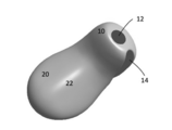
- canal insertion
- insertion part
- Prior art date
- Legal status (The legal status is an assumption and is not a legal conclusion. Google has not performed a legal analysis and makes no representation as to the accuracy of the status listed.)
- Ceased
Links
Images






Classifications
-
- H—ELECTRICITY
- H04—ELECTRIC COMMUNICATION TECHNIQUE
- H04R—LOUDSPEAKERS, MICROPHONES, GRAMOPHONE PICK-UPS OR LIKE ACOUSTIC ELECTROMECHANICAL TRANSDUCERS; ELECTRIC HEARING AIDS; PUBLIC ADDRESS SYSTEMS
- H04R1/00—Details of transducers, loudspeakers or microphones
- H04R1/10—Earpieces; Attachments therefor ; Earphones; Monophonic headphones
- H04R1/1016—Earpieces of the intra-aural type
-
- H—ELECTRICITY
- H04—ELECTRIC COMMUNICATION TECHNIQUE
- H04R—LOUDSPEAKERS, MICROPHONES, GRAMOPHONE PICK-UPS OR LIKE ACOUSTIC ELECTROMECHANICAL TRANSDUCERS; ELECTRIC HEARING AIDS; PUBLIC ADDRESS SYSTEMS
- H04R25/00—Electric hearing aids
- H04R25/65—Housing parts, e.g. shells, tips or moulds, or their manufacture
- H04R25/652—Ear tips; Ear moulds
-
- H—ELECTRICITY
- H04—ELECTRIC COMMUNICATION TECHNIQUE
- H04R—LOUDSPEAKERS, MICROPHONES, GRAMOPHONE PICK-UPS OR LIKE ACOUSTIC ELECTROMECHANICAL TRANSDUCERS; ELECTRIC HEARING AIDS; PUBLIC ADDRESS SYSTEMS
- H04R25/00—Electric hearing aids
- H04R25/02—Electric hearing aids adapted to be supported entirely by ear
-
- H—ELECTRICITY
- H04—ELECTRIC COMMUNICATION TECHNIQUE
- H04R—LOUDSPEAKERS, MICROPHONES, GRAMOPHONE PICK-UPS OR LIKE ACOUSTIC ELECTROMECHANICAL TRANSDUCERS; ELECTRIC HEARING AIDS; PUBLIC ADDRESS SYSTEMS
- H04R25/00—Electric hearing aids
- H04R25/65—Housing parts, e.g. shells, tips or moulds, or their manufacture
- H04R25/652—Ear tips; Ear moulds
- H04R25/656—Non-customized, universal ear tips, i.e. ear tips which are not specifically adapted to the size or shape of the ear or ear canal
-
- H—ELECTRICITY
- H04—ELECTRIC COMMUNICATION TECHNIQUE
- H04R—LOUDSPEAKERS, MICROPHONES, GRAMOPHONE PICK-UPS OR LIKE ACOUSTIC ELECTROMECHANICAL TRANSDUCERS; ELECTRIC HEARING AIDS; PUBLIC ADDRESS SYSTEMS
- H04R2225/00—Details of deaf aids covered by H04R25/00, not provided for in any of its subgroups
- H04R2225/025—In the ear hearing aids [ITE] hearing aids
-
- H—ELECTRICITY
- H04—ELECTRIC COMMUNICATION TECHNIQUE
- H04R—LOUDSPEAKERS, MICROPHONES, GRAMOPHONE PICK-UPS OR LIKE ACOUSTIC ELECTROMECHANICAL TRANSDUCERS; ELECTRIC HEARING AIDS; PUBLIC ADDRESS SYSTEMS
- H04R2460/00—Details of hearing devices, i.e. of ear- or headphones covered by H04R1/10 or H04R5/033 but not provided for in any of their subgroups, or of hearing aids covered by H04R25/00 but not provided for in any of its subgroups
- H04R2460/11—Aspects relating to vents, e.g. shape, orientation, acoustic properties in ear tips of hearing devices to prevent occlusion
Definitions
- the present invention relates to an outer ear wearer for audio equipment.
- hearing aids for example, hearing aids, voice reproduction devices, voice communication devices, and acoustic devices (hearing devices) such as environmental measures devices (that is, noise cancellers) are used, and the outer ear wearer used by being inserted into the user's ear canal is known.
- acoustic devices such as environmental measures devices (that is, noise cancellers)
- Patent Document 1 As a hearing aid, as disclosed in Patent Document 1, there is a closed-type ready-made product that completely closes the ear canal, and the wearing state is stable as in the custom-made product. See also Patent Document 2 as a document that discloses the prior art related to the present invention.
- the outer ear wearing tool described in Patent Document 2 is made of a relatively hard material, and includes a tubular ear canal insertion portion to be inserted into the external auditory canal and a conical ear canal placement portion following the tubular ear canal insertion portion.
- the ear canal insertion portion does not fit the ear canal of all users.
- the tubular ear canal insertion portion can be rotated in the ear canal or its position can be moved in the axial direction in the ear canal to enhance the fit to the ear canal.
- the ear canal cavity placement portion interferes with the peripheral wall of the ear canal cavity, and the external auditory canal insertion portion is rotated. It may hinder movement.
- the present invention has been made to solve the above problems, and the first aspect is defined as follows. That is, The tubular ear canal insertion part and the concha cavity placement part are arranged on a virtual spherical surface,
- the tubular ear canal insertion part is an ear canal attachment that can rotate around its long axis while being inserted into the ear canal.
- the ear canal insertion portion since the ear canal insertion portion is formed in a tubular shape, the ear canal insertion portion rotates about the long axis while being inserted into the ear canal. Alternatively, the position can be shifted (displaced) in the ear canal in the long axis direction.
- the ear canal placement part since the ear canal placement part is arranged on the same virtual spherical surface as the ear canal insertion part, the ear canal placement part is the ear canal space with the ear canal insertion part inserted into the ear canal. It will be in a state along the inner wall surface of. This is because the posterior wall of the ear canal entrance-the inner wall of the concha cavity is substantially along the virtual spherical surface.
- the sphere here is not limited to a true sphere, but also includes an ellipsoid and other variants of a true sphere. Therefore, when the external auditory canal insertion portion inserted into the external auditory canal is rotated around its long axis or displaced in the axial direction, the resistance of the concha cavity arrangement portion becomes extremely small. As a result, the position of the outer ear attachment with respect to the ear canal can be easily adjusted and with a large degree of freedom.
- the ear canal insertion portion is formed into a cylindrical shape or an elliptical tubular shape.
- the ear canal insertion part cylindrical or elliptical tubular, it becomes easy to rotate the ear canal insertion part about the long axis in the state of being inserted into the ear canal.
- the ear canal insertion part cylindrical, rotation in the ear canal is most facilitated.
- By forming the ear canal insertion portion into an elliptical cylinder it becomes easier for a part of the ellipse to come into close contact with the inner peripheral surface of the ear canal when it is rotated, so that the sound effect is stabilized.
- a gap can be formed between the ear canal and the inner peripheral surface of the ear canal on the opposite side of the contacted portion. As a result, it is easy to prevent a feeling of ear closure due to the sealing of the ear canal by the ear canal insertion portion.
- the third aspect of the present invention is defined as follows. That is, in the outer ear wearing device specified in the first or second aspect, the diameter of the ear canal insertion portion gradually increases from the tip thereof toward the concha cavity arrangement portion. This prevents the external auditory canal insertion portion from being deeply inserted into the external auditory canal, thereby ensuring an appropriate insertion state of the external auditory canal insertion portion.
- the diameter of the base end side of the ear canal insertion portion that is, the connecting portion with the ear canal cavity arrangement portion to a large diameter, the insertion state of the outer ear attachment is stabilized.
- the back side (outside when viewed from the user) of the external auditory canal insertion portion contacts the tragus, while the ventral side thereof contacts the posterior wall of the external auditory canal entrance.
- this portion can be sandwiched between the tragus and the posterior wall of the ear canal entrance. Therefore, the wearing state of the outer ear fitting is stable.
- the fourth aspect of the present invention is defined as follows. That is, in the outer ear attachment specified in the second or third aspect, the ear canal insertion portion has an elliptical cross section, and the major axis of the ellipse is in the vertical direction.
- the vertical direction refers to the direction of gravity when the ear canal insertion part is inserted into the ear canal, and includes not only the physically strict gravity direction but also a slight inclination in consideration of human operation.
- the human ear canal is generally vertically long, it is preferable that the ear canal insertion portion also has a vertically long elliptical cylinder.
- the fifth aspect of the present invention is defined as follows. That is, in the outer ear attachment specified in any of the first to fourth aspects, the ear canal cavity arrangement portion is wider in the vertical direction than the external auditory canal insertion portion when viewed from the tip side of the external auditory canal insertion portion. By forming the concha cavity arrangement portion wide in the vertical direction, it can be more stably attached to the concha cavity.
- the sixth aspect of the present invention is defined as follows. That is, in the outer ear wearing device specified in the first to fifth aspects, a ridge is formed on the ventral side surface of the concha cavity arrangement portion. Due to such ridges, the feeling of attachment of the concha cavity arrangement portion to the concha cavity is improved. This is because the ridges make line contact with the living tissue on the inner wall of the concha cavity, and the contact area becomes as small as possible. Further, as described above, this outer ear wearing device may be sandwiched between the tragus and the posterior wall of the entrance of the ear canal. There is a gap between both sides and the inner wall of the tragus cavity. This gap serves as play, and when the ear canal insertion portion rotates around its long axis, the mobility of the concha cavity arrangement portion is improved. That is, the rotation of the ear canal insertion portion becomes smooth.
- the seventh aspect of the present invention is defined as follows. That is, in the outer ear attachment specified in any of the first to sixth aspects, the sound output portion formed at the tip of the ear canal insertion portion is arranged on the ventral side. As a result, sound waves can be efficiently introduced in the direction of the eardrum.
- the eighth aspect of the present invention is defined as follows. That is, in the outer ear attachment specified in any of the first to seventh aspects, a groove (vent) is formed on the lower surface of the ear canal insertion portion.
- a groove is formed on the lower surface of the ear canal insertion portion.
- the groove is provided on the lower side because the upper surface of the ear canal insertion portion is applied to the upper wall of the ear canal. Further, since the microphone is arranged on the upper side of the hearing aid, it is convenient to form the vent on the lower side and separate it from the microphone to prevent howling.
- FIG. 1 is a perspective view of a basic form of the outer ear wearing device of the present invention.
- FIG. 2 also shows the ventral side surface of the ear canal wearing device of FIG. 1 as viewed from the direction of the arrow on line II.
- FIG. 3 is a perspective view showing the outer ear wearing device of FIG. 1 applied to a hearing aid.
- FIG. 4 is a schematic view showing a state when the ear canal insertion portion of the ear canal fitting of FIG. 3 is inserted into the ear canal.
- FIG. 5 is a perspective view of the ear canal attachment of FIG. 3 as viewed from the direction of the arrow on the V line.
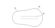
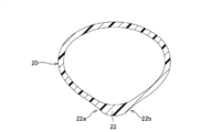
- FIG. 6 is a cross-sectional view of the concha cavity arrangement portion.
- FIG. 1 is a perspective view of a basic form of the outer ear wearing device of the present invention.
- FIG. 2 also shows the ventral side surface of the ear canal wearing device of FIG. 1 as viewed from the direction of the arrow on line II.
- FIG. 7 shows a state in which the external auditory canal insertion portion of the external ear canal fitting of FIG. 1 is inserted into the external auditory canal.
- FIG. 8 is a cross-sectional view showing a state of attachment between the ear canal and the ear canal insertion portion.
- FIG. 9 shows a state in which the ear canal insertion portion of the outer ear wearing tool of FIG. 1 is inserted into the ear canal and then rotated.
- FIG. 10 is a perspective view showing an example in which an outer ear fitting is applied to a vibrating hearing aid.
- FIG. 11 is a perspective view showing an example (for the left ear) in which the outer ear fitting is applied to another type of hearing aid, for example, the ear mold of the hearing aid.
- FIG. 12 is a perspective view taken along the line of the XII in FIG.
- FIG. 13 is a perspective view of the XIII arrow line of view in FIG.
- FIG. 1 shows the outer ear attachment 1 of the embodiment.
- the outer ear attachment 1 includes an ear canal insertion portion 10 and an ear canal cavity arrangement portion 20.
- the ear canal insertion portion 10 and the ear canal cavity arrangement portion 20 are arranged on the virtual spherical surface O shown by the alternate long and short dash line in the figure. More specifically, the ventral side surface (the surface on the side in contact with a person) of the external auditory canal insertion portion 10 and the concha cavity arrangement portion 20 may be arranged on the virtual spherical surface O.
- both the ear canal insertion portion 10 and the ear canal cavity arrangement portion 20 are formed in a tubular shape, it can be considered that their axes are arranged on a virtual spherical surface.
- the tubular shape is formed because a small speaker or the like may be housed inside them. Further, the weight is reduced by making it tubular, that is, hollow.
- the axes of the ear canal insertion portion 10 and the ear canal cavity arrangement portion 20 are preferably located on the same plane orthogonal to the tangent line of the virtual spherical surface in order to simplify the structure. As long as it is arranged on the virtual spherical surface as described above, it may be bent three-dimensionally.
- the outer ear fitting 1 can be made of a material harder than human tissue. Examples of such materials include resin materials such as methacrylic resin (acrylic), which is generally called thermoplastic, and excellent moldability and durability (chemical resistance, heat resistance, light resistance), and biocompatibility of stainless steel, titanium and the like. Examples of metal materials having excellent properties can be mentioned. It is preferable to mold using such a material. It can also be formed by laminated modeling. Examples of the soft material include silicone rubber and the like.
- the ear canal insertion portion 10 is a tubular member having an elliptical cross section.
- the major axis of the ellipse is the vertical direction. This is because, in general, the human ear canal is long in the vertical direction.
- the ear canal insertion portion 10 has a smaller diameter toward the tip side (see FIG. 2).
- the shape of the cross section is similar in the axial direction, but the shape of the cross section can be made irregular along the axial direction.
- the ear canal insertion portion 10 has a large diameter at its base end (that is, a connection portion with the ear canal cavity arrangement portion 20).
- An opening 12 can be formed on the ventral side of the tip of the ear canal insertion portion 10 (see FIG. 3). This opening 12 serves as an audio output portion.
- the sound output from the opening 12 reaches the eardrum directly in a state where the ear canal insertion portion 10 is inserted into the ear canal.
- the opening is in the center of the ear canal insertion portion 10 or on the dorsal side thereof, the probability that the sound output from the opening interferes with the peripheral wall of the ear canal before reaching the eardrum increases.
- a microphone hole 25 may be provided on the dorsal side of the concha cavity arrangement portion 20 (see FIG. 5).
- the parietal cavity arrangement portion 20 is integrally formed from the proximal end portion of the external auditory canal insertion portion 10.
- the parietal cavity arrangement portion 20 becomes wider as it is separated from the proximal end portion of the external auditory canal insertion portion 10. This is to ensure the stability of wearing by ensuring contact with the inner wall of the concha cavity.
- a ridge 22 is formed on the ventral side of the concha cavity arrangement portion 20.
- the height of the ridge 22 is not particularly limited, but is about 1 to 5 mm.
- the ridge 22 has a chevron-shaped cross section, and slightly concave slopes 22a and 22b are formed on both sides.
- the ridge 22 is continuously formed from the tip of the concha cavity arranging portion 20 to the connecting portion with the external auditory canal insertion portion 10.
- the outer ear fitting 1 thus formed inserts the ear canal insertion portion 10 into the human ear canal 100 so that its major axis (in the cross section) is in the vertical direction, as shown in FIG. 7, for example.
- the state of insertion is shown by a dotted line in FIG.
- the shape of the human ear canal varies widely, but in this example, since the major axis of the ear canal 100 (in the cross section) is longer than the major axis of the ear canal insertion section 10 (in the cross section), the ear canal insertion portion 10 is inserted into the ear canal 100. In this state, a random gap is formed between the ear canal 100 and the ear canal insertion portion 10.
- the external auditory canal insertion portion 10 when the external auditory canal insertion portion 10 is rotated counterclockwise (in the case of the right ear) from the state shown in FIG. 7, the external auditory canal insertion portion 10 comes into close contact with the anterior upper wall of the external auditory canal as shown by the solid line in FIG. .. Since the ear canal 100 is not a straight hole, in order to obtain close contact between the two, not only the ear canal insertion portion 10 is rotated about its axis, but also the ear canal insertion portion 10 is moved in the major axis direction thereof. Tilt at the same time. That is, it is necessary to rotate the whole three-dimensionally.
- both the ventral side surface of the external auditory canal insertion portion 10 and the ventral side surface of the parietal cavity arrangement portion 20 are arranged on the virtual spherical surface, the three-dimensional rotation is facilitated. Further, since the ridge 22 is formed on the ventral side surface of the concha cavity arrangement portion 20, when the external auditory canal insertion portion 10 is rotated around its long axis, both sides of the ridge 22 and the inner wall of the concha cavity are formed. Since a space is formed between the two and the ear canal cavity arrangement portion 20, the space is easily tilted using the space. As a result, the resistance to rotation of the ear canal insertion portion 10 is reduced.
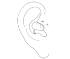
- FIG. 9 shows an example of the final wearing state of the outer ear wearing tool 1.
- the external auditory canal insertion portion 10 is attached so as to follow the shape of the human ear, more specifically, the shape of the concha cavity-the entrance of the external auditory canal-the external auditory canal. Insert and rotate the tool 1 three-dimensionally while tilting it from time to time.
- the ear canal insertion portion 10 is in a state along the upper side wall of the ear canal 100 (see the solid line in FIG. 8).
- the base end portion (connecting portion with the concha cavity arrangement portion 20) of the external auditory canal insertion portion 10 having a relatively large diameter is sandwiched between the tragus and the posterior wall of the external auditory canal entrance, the external auditory canal insertion portion 10
- the rotation around the long axis and the movement in the long axis direction are restricted, and the position is stable.
- the concha cavity arranging portion 20 is designed to become wider from the connecting portion with the external auditory canal insertion portion 10 toward the posterior end, it is held and stabilized at at least one place in the concha cavity. It has become. Further, this limits the displacement of the ear canal insertion portion 10, and the inside of the ear canal is stably held by surface contact on the upper wall.
- the ridges 22 formed on the ventral side surface of the concha cavity arranging portion 20 improve the wearing feeling of the concha cavity arranging portion 20. This is because the contact area between the concha cavity arranging portion 20 and the inner wall of the concha cavity becomes small.
- FIG. 10 shows an example in which the outer ear fitting 10 is applied to a vibrating hearing aid.
- reference numeral 30 indicates a vibrating device
- reference numeral 40 indicates a connecting portion.
- the power supply line and signal line to the vibrating device 30 are drawn out via the connecting portion 40.
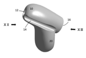
- FIG. 11 shows an example in which the outer ear fitting 10 is applied to the ear mold of a hearing aid.
- the groove 14 is formed by inflating the lower side surface of the ear canal insertion portion 10.
- the groove 14 acts as a vent to prevent the entire peripheral surface of the external auditory canal insertion portion 10 from coming into close contact with the human external auditory canal wall.
- the groove 14 is continuous from the tip of the ear canal insertion portion 10 toward the outside.
- FIG. 12 is a perspective view taken along the line of the XII in FIG.
- FIG. 13 is a perspective view of the XIII arrow line of view in FIG.
- Ear canal insertion part 10 Ear canal insertion part 12 Opening 14 Groove 16 Connection part 20
- Ear canal cavity arrangement part 22 Convex 22a Slightly concave slope 22b Slightly concave slope 25
- Microphone 30 Vibration device 40 Connection part 100 Ear canal O Virtual spherical surface
Landscapes
- Engineering & Computer Science (AREA)
- Physics & Mathematics (AREA)
- Acoustics & Sound (AREA)
- Signal Processing (AREA)
- Health & Medical Sciences (AREA)
- General Health & Medical Sciences (AREA)
- Neurosurgery (AREA)
- Otolaryngology (AREA)
- Manufacturing & Machinery (AREA)
- Headphones And Earphones (AREA)
Priority Applications (3)
| Application Number | Priority Date | Filing Date | Title |
|---|---|---|---|
| EP20881723.9A EP4054203A4 (en) | 2019-10-30 | 2020-10-29 | DEVICE TO BE WEAR ON THE OUTER EAR |
| US17/770,819 US11985484B2 (en) | 2019-10-30 | 2020-10-29 | Implement to be worn on outer ear |
| JP2021553697A JP7634883B2 (ja) | 2019-10-30 | 2020-10-29 | 外耳装着具 |
Applications Claiming Priority (2)
| Application Number | Priority Date | Filing Date | Title |
|---|---|---|---|
| JP2019197472 | 2019-10-30 | ||
| JP2019-197472 | 2019-10-30 |
Publications (1)
| Publication Number | Publication Date |
|---|---|
| WO2021085559A1 true WO2021085559A1 (ja) | 2021-05-06 |
Family
ID=75715177
Family Applications (1)
| Application Number | Title | Priority Date | Filing Date |
|---|---|---|---|
| PCT/JP2020/040698 Ceased WO2021085559A1 (ja) | 2019-10-30 | 2020-10-29 | 外耳装着具 |
Country Status (4)
| Country | Link |
|---|---|
| US (1) | US11985484B2 (https=) |
| EP (1) | EP4054203A4 (https=) |
| JP (1) | JP7634883B2 (https=) |
| WO (1) | WO2021085559A1 (https=) |
Cited By (1)
| Publication number | Priority date | Publication date | Assignee | Title |
|---|---|---|---|---|
| JP2024066058A (ja) * | 2022-11-01 | 2024-05-15 | オンキヨー株式会社 | 電子機器 |
Families Citing this family (1)
| Publication number | Priority date | Publication date | Assignee | Title |
|---|---|---|---|---|
| US11877110B2 (en) * | 2022-01-13 | 2024-01-16 | Bose Corporation | Flow relief features embedded in cosmetic surface of wearables |
Citations (15)
| Publication number | Priority date | Publication date | Assignee | Title |
|---|---|---|---|---|
| JPS5518825U (https=) * | 1978-07-20 | 1980-02-06 | ||
| US4311206A (en) * | 1978-05-15 | 1982-01-19 | Johnson Rubein V | Hearing aid ear mold with improved discrimination |
| JPH03117999A (ja) * | 1989-09-30 | 1991-05-20 | Sony Corp | 電気音響変換器及び音響再生システム |
| JPH06113001A (ja) * | 1992-02-24 | 1994-04-22 | Pilot Corp:The | 片耳装着型送受話器 |
| JPH0644504U (ja) * | 1992-11-21 | 1994-06-14 | 株式会社堀場製作所 | 耳式体温計 |
| JPH08195999A (ja) * | 1995-01-17 | 1996-07-30 | Rion Co Ltd | 耳穴装用具 |
| JP2684812B2 (ja) | 1990-03-27 | 1997-12-03 | リオン 株式会社 | 挿耳形補聴器 |
| JPH10126873A (ja) * | 1996-10-21 | 1998-05-15 | Matsushita Electric Ind Co Ltd | 骨振動型マイクロホンおよび振動ピックアップ |
| JP2012525799A (ja) * | 2009-04-30 | 2012-10-22 | ヴェルト メディカル ソリューションズ、エルエルシー | イヤホンシステム |
| JP2012222682A (ja) * | 2011-04-12 | 2012-11-12 | Tetsuhiro Tanaka | 骨伝導イヤホン |
| JP2013058880A (ja) * | 2011-09-08 | 2013-03-28 | Rion Co Ltd | 既製耳あな型補聴器 |
| JP2014508553A (ja) * | 2010-12-16 | 2014-04-10 | サイオン・ニューロスティム,リミテッド・ライアビリティ・カンパニー | 医師による監視下で患者に神経刺激を送達するためのシステム、方法及び装置 |
| JP2015521424A (ja) * | 2012-05-11 | 2015-07-27 | ハーマン インターナショナル インダストリーズ インコーポレイテッド | 生理学的センサ付きのイヤホン及び小型イヤホン |
| JP2017139649A (ja) | 2016-02-04 | 2017-08-10 | パナソニックIpマネジメント株式会社 | 補聴器及びイヤーチップ |
| JP2018098596A (ja) * | 2016-12-12 | 2018-06-21 | リオン株式会社 | 耳あな型補聴器 |
Family Cites Families (12)
| Publication number | Priority date | Publication date | Assignee | Title |
|---|---|---|---|---|
| DE8518681U1 (de) | 1985-06-27 | 1986-06-12 | Siemens AG, 1000 Berlin und 8000 München | Hörhilfe |
| US6122388A (en) * | 1997-11-26 | 2000-09-19 | Earcandies L.L.C. | Earmold device |
| US7014010B2 (en) | 2000-06-30 | 2006-03-21 | Phonak Ag | Method for manufacturing an ear device and ear device |
| US7394909B1 (en) * | 2000-09-25 | 2008-07-01 | Phonak Ag | Hearing device with embedded channnel |
| DE102004048214B3 (de) * | 2004-09-30 | 2006-06-14 | Siemens Audiologische Technik Gmbh | Universelles Ohrstück und akustisches Gerät mit einem derartigen Ohrstück |
| US20090202098A1 (en) | 2008-02-13 | 2009-08-13 | Plantronics, Inc. | Occluding Earbud System and Method |
| US9237968B1 (en) | 2012-05-09 | 2016-01-19 | Scott Alan Orman | Water sports ear plug |
| US9479859B2 (en) * | 2013-11-18 | 2016-10-25 | 3M Innovative Properties Company | Concha-fit electronic hearing protection device |
| EP3248394B1 (en) * | 2015-01-19 | 2024-12-11 | 3M Innovative Properties Company | Hearing protection device with convoluted acoustic horn |
| CN109068994A (zh) * | 2016-04-17 | 2018-12-21 | 莱夫毕恩技术有限公司 | 带有生理传感器及稳固元件的耳机 |
| US10869115B2 (en) | 2018-01-03 | 2020-12-15 | Logitech Europe S.A. | Apparatus and method of forming a custom earpiece |
| WO2019187610A1 (ja) * | 2018-03-26 | 2019-10-03 | ソニー株式会社 | 音響出力装置 |
-
2020
- 2020-10-29 EP EP20881723.9A patent/EP4054203A4/en active Pending
- 2020-10-29 WO PCT/JP2020/040698 patent/WO2021085559A1/ja not_active Ceased
- 2020-10-29 US US17/770,819 patent/US11985484B2/en active Active
- 2020-10-29 JP JP2021553697A patent/JP7634883B2/ja active Active
Patent Citations (15)
| Publication number | Priority date | Publication date | Assignee | Title |
|---|---|---|---|---|
| US4311206A (en) * | 1978-05-15 | 1982-01-19 | Johnson Rubein V | Hearing aid ear mold with improved discrimination |
| JPS5518825U (https=) * | 1978-07-20 | 1980-02-06 | ||
| JPH03117999A (ja) * | 1989-09-30 | 1991-05-20 | Sony Corp | 電気音響変換器及び音響再生システム |
| JP2684812B2 (ja) | 1990-03-27 | 1997-12-03 | リオン 株式会社 | 挿耳形補聴器 |
| JPH06113001A (ja) * | 1992-02-24 | 1994-04-22 | Pilot Corp:The | 片耳装着型送受話器 |
| JPH0644504U (ja) * | 1992-11-21 | 1994-06-14 | 株式会社堀場製作所 | 耳式体温計 |
| JPH08195999A (ja) * | 1995-01-17 | 1996-07-30 | Rion Co Ltd | 耳穴装用具 |
| JPH10126873A (ja) * | 1996-10-21 | 1998-05-15 | Matsushita Electric Ind Co Ltd | 骨振動型マイクロホンおよび振動ピックアップ |
| JP2012525799A (ja) * | 2009-04-30 | 2012-10-22 | ヴェルト メディカル ソリューションズ、エルエルシー | イヤホンシステム |
| JP2014508553A (ja) * | 2010-12-16 | 2014-04-10 | サイオン・ニューロスティム,リミテッド・ライアビリティ・カンパニー | 医師による監視下で患者に神経刺激を送達するためのシステム、方法及び装置 |
| JP2012222682A (ja) * | 2011-04-12 | 2012-11-12 | Tetsuhiro Tanaka | 骨伝導イヤホン |
| JP2013058880A (ja) * | 2011-09-08 | 2013-03-28 | Rion Co Ltd | 既製耳あな型補聴器 |
| JP2015521424A (ja) * | 2012-05-11 | 2015-07-27 | ハーマン インターナショナル インダストリーズ インコーポレイテッド | 生理学的センサ付きのイヤホン及び小型イヤホン |
| JP2017139649A (ja) | 2016-02-04 | 2017-08-10 | パナソニックIpマネジメント株式会社 | 補聴器及びイヤーチップ |
| JP2018098596A (ja) * | 2016-12-12 | 2018-06-21 | リオン株式会社 | 耳あな型補聴器 |
Non-Patent Citations (1)
| Title |
|---|
| See also references of EP4054203A4 |
Cited By (2)
| Publication number | Priority date | Publication date | Assignee | Title |
|---|---|---|---|---|
| JP2024066058A (ja) * | 2022-11-01 | 2024-05-15 | オンキヨー株式会社 | 電子機器 |
| JP7832496B2 (ja) | 2022-11-01 | 2026-03-18 | オンキヨー株式会社 | 電子機器 |
Also Published As
| Publication number | Publication date |
|---|---|
| US11985484B2 (en) | 2024-05-14 |
| EP4054203A1 (en) | 2022-09-07 |
| US20220377477A1 (en) | 2022-11-24 |
| EP4054203A4 (en) | 2024-01-17 |
| JP7634883B2 (ja) | 2025-02-25 |
| JPWO2021085559A1 (https=) | 2021-05-06 |
Similar Documents
| Publication | Publication Date | Title |
|---|---|---|
| US9955249B2 (en) | Earpiece with movable joint | |
| US10009680B2 (en) | Retaining structure for an earpiece | |
| JP7447933B2 (ja) | イヤホン及びサポータ | |
| US7627131B2 (en) | Flexible earpiece for a hearing aid | |
| JP5934358B2 (ja) | イヤーピースパッシブノイズ減衰 | |
| US7720242B2 (en) | Flexible joint for extended wear hearing device | |
| US8503707B2 (en) | Sealing retainer for extended wear hearing devices | |
| JP2023509594A (ja) | 開放型オーディオデバイス | |
| KR100968006B1 (ko) | 결합장치의 보유유지가 개선된 이어몰드 | |
| US10924842B2 (en) | Audio device | |
| US10820084B2 (en) | Ear tip sealing structure | |
| US11381897B2 (en) | Variable eartip for earphone | |
| CN102577437A (zh) | 耳件系统 | |
| EP3334179B1 (en) | Hearing aid with an extended dome | |
| JPS61238198A (ja) | カスタム挿耳型補聴器 | |
| WO2021085559A1 (ja) | 外耳装着具 | |
| CN205545822U (zh) | 一种具有耳道自适应功能的耳塞套 | |
| US20180103310A1 (en) | Light weight headphone | |
| KR20040094406A (ko) | 보청기 | |
| JP7320316B1 (ja) | オープン型イヤホン | |
| CN107079216A (zh) | 耳机系统 |
Legal Events
| Date | Code | Title | Description |
|---|---|---|---|
| 121 | Ep: the epo has been informed by wipo that ep was designated in this application |
Ref document number: 20881723 Country of ref document: EP Kind code of ref document: A1 |
|
| DPE1 | Request for preliminary examination filed after expiration of 19th month from priority date (pct application filed from 20040101) | ||
| ENP | Entry into the national phase |
Ref document number: 2021553697 Country of ref document: JP Kind code of ref document: A |
|
| NENP | Non-entry into the national phase |
Ref country code: DE |
|
| ENP | Entry into the national phase |
Ref document number: 2020881723 Country of ref document: EP Effective date: 20220530 |