WO2021085559A1 - 外耳装着具 - Google Patents
外耳装着具 Download PDFInfo
- Publication number
- WO2021085559A1 WO2021085559A1 PCT/JP2020/040698 JP2020040698W WO2021085559A1 WO 2021085559 A1 WO2021085559 A1 WO 2021085559A1 JP 2020040698 W JP2020040698 W JP 2020040698W WO 2021085559 A1 WO2021085559 A1 WO 2021085559A1
- Authority
- WO
- WIPO (PCT)
- Prior art keywords
- ear canal
- ear
- insertion portion
- canal insertion
- insertion part
- Prior art date
Links
- 210000000883 ear external Anatomy 0.000 title claims abstract description 36
- 210000000613 ear canal Anatomy 0.000 claims abstract description 200
- 238000003780 insertion Methods 0.000 claims abstract description 100
- 230000037431 insertion Effects 0.000 claims abstract description 100
- 230000000694 effects Effects 0.000 abstract description 2
- 238000013022 venting Methods 0.000 abstract description 2
- 241000746998 Tragus Species 0.000 description 5
- 239000000463 material Substances 0.000 description 5
- 230000002093 peripheral effect Effects 0.000 description 5
- 238000004519 manufacturing process Methods 0.000 description 4
- 210000003454 tympanic membrane Anatomy 0.000 description 4
- 230000001936 parietal effect Effects 0.000 description 3
- 230000005484 gravity Effects 0.000 description 2
- RTAQQCXQSZGOHL-UHFFFAOYSA-N Titanium Chemical compound [Ti] RTAQQCXQSZGOHL-UHFFFAOYSA-N 0.000 description 1
- NIXOWILDQLNWCW-UHFFFAOYSA-N acrylic acid group Chemical group C(C=C)(=O)O NIXOWILDQLNWCW-UHFFFAOYSA-N 0.000 description 1
- 238000004891 communication Methods 0.000 description 1
- 238000006073 displacement reaction Methods 0.000 description 1
- 239000013013 elastic material Substances 0.000 description 1
- 230000007613 environmental effect Effects 0.000 description 1
- 230000001788 irregular Effects 0.000 description 1
- 239000007769 metal material Substances 0.000 description 1
- 239000000113 methacrylic resin Substances 0.000 description 1
- 238000012986 modification Methods 0.000 description 1
- 230000004048 modification Effects 0.000 description 1
- 238000000465 moulding Methods 0.000 description 1
- 239000011347 resin Substances 0.000 description 1
- 229920005989 resin Polymers 0.000 description 1
- 238000007789 sealing Methods 0.000 description 1
- 229920002379 silicone rubber Polymers 0.000 description 1
- 239000004945 silicone rubber Substances 0.000 description 1
- 238000009751 slip forming Methods 0.000 description 1
- 239000007779 soft material Substances 0.000 description 1
- 229910001220 stainless steel Inorganic materials 0.000 description 1
- 239000010935 stainless steel Substances 0.000 description 1
- 239000000126 substance Substances 0.000 description 1
- 229920001169 thermoplastic Polymers 0.000 description 1
- 239000004416 thermosoftening plastic Substances 0.000 description 1
- 239000010936 titanium Substances 0.000 description 1
- 229910052719 titanium Inorganic materials 0.000 description 1
Images


Classifications
-
- H—ELECTRICITY
- H04—ELECTRIC COMMUNICATION TECHNIQUE
- H04R—LOUDSPEAKERS, MICROPHONES, GRAMOPHONE PICK-UPS OR LIKE ACOUSTIC ELECTROMECHANICAL TRANSDUCERS; DEAF-AID SETS; PUBLIC ADDRESS SYSTEMS
- H04R1/00—Details of transducers, loudspeakers or microphones
- H04R1/10—Earpieces; Attachments therefor ; Earphones; Monophonic headphones
- H04R1/1016—Earpieces of the intra-aural type
-
- H—ELECTRICITY
- H04—ELECTRIC COMMUNICATION TECHNIQUE
- H04R—LOUDSPEAKERS, MICROPHONES, GRAMOPHONE PICK-UPS OR LIKE ACOUSTIC ELECTROMECHANICAL TRANSDUCERS; DEAF-AID SETS; PUBLIC ADDRESS SYSTEMS
- H04R25/00—Deaf-aid sets, i.e. electro-acoustic or electro-mechanical hearing aids; Electric tinnitus maskers providing an auditory perception
- H04R25/65—Housing parts, e.g. shells, tips or moulds, or their manufacture
- H04R25/652—Ear tips; Ear moulds
-
- H—ELECTRICITY
- H04—ELECTRIC COMMUNICATION TECHNIQUE
- H04R—LOUDSPEAKERS, MICROPHONES, GRAMOPHONE PICK-UPS OR LIKE ACOUSTIC ELECTROMECHANICAL TRANSDUCERS; DEAF-AID SETS; PUBLIC ADDRESS SYSTEMS
- H04R25/00—Deaf-aid sets, i.e. electro-acoustic or electro-mechanical hearing aids; Electric tinnitus maskers providing an auditory perception
- H04R25/02—Deaf-aid sets, i.e. electro-acoustic or electro-mechanical hearing aids; Electric tinnitus maskers providing an auditory perception adapted to be supported entirely by ear
-
- H—ELECTRICITY
- H04—ELECTRIC COMMUNICATION TECHNIQUE
- H04R—LOUDSPEAKERS, MICROPHONES, GRAMOPHONE PICK-UPS OR LIKE ACOUSTIC ELECTROMECHANICAL TRANSDUCERS; DEAF-AID SETS; PUBLIC ADDRESS SYSTEMS
- H04R25/00—Deaf-aid sets, i.e. electro-acoustic or electro-mechanical hearing aids; Electric tinnitus maskers providing an auditory perception
- H04R25/65—Housing parts, e.g. shells, tips or moulds, or their manufacture
- H04R25/652—Ear tips; Ear moulds
- H04R25/656—Non-customized, universal ear tips, i.e. ear tips which are not specifically adapted to the size or shape of the ear or ear canal
-
- H—ELECTRICITY
- H04—ELECTRIC COMMUNICATION TECHNIQUE
- H04R—LOUDSPEAKERS, MICROPHONES, GRAMOPHONE PICK-UPS OR LIKE ACOUSTIC ELECTROMECHANICAL TRANSDUCERS; DEAF-AID SETS; PUBLIC ADDRESS SYSTEMS
- H04R2225/00—Details of deaf aids covered by H04R25/00, not provided for in any of its subgroups
- H04R2225/025—In the ear hearing aids [ITE] hearing aids
-
- H—ELECTRICITY
- H04—ELECTRIC COMMUNICATION TECHNIQUE
- H04R—LOUDSPEAKERS, MICROPHONES, GRAMOPHONE PICK-UPS OR LIKE ACOUSTIC ELECTROMECHANICAL TRANSDUCERS; DEAF-AID SETS; PUBLIC ADDRESS SYSTEMS
- H04R2460/00—Details of hearing devices, i.e. of ear- or headphones covered by H04R1/10 or H04R5/033 but not provided for in any of their subgroups, or of hearing aids covered by H04R25/00 but not provided for in any of its subgroups
- H04R2460/11—Aspects relating to vents, e.g. shape, orientation, acoustic properties in ear tips of hearing devices to prevent occlusion
Definitions
- the present invention relates to an outer ear wearer for audio equipment.
- hearing aids for example, hearing aids, voice reproduction devices, voice communication devices, and acoustic devices (hearing devices) such as environmental measures devices (that is, noise cancellers) are used, and the outer ear wearer used by being inserted into the user's ear canal is known.
- acoustic devices such as environmental measures devices (that is, noise cancellers)
- Patent Document 1 As a hearing aid, as disclosed in Patent Document 1, there is a closed-type ready-made product that completely closes the ear canal, and the wearing state is stable as in the custom-made product. See also Patent Document 2 as a document that discloses the prior art related to the present invention.
- the outer ear wearing tool described in Patent Document 2 is made of a relatively hard material, and includes a tubular ear canal insertion portion to be inserted into the external auditory canal and a conical ear canal placement portion following the tubular ear canal insertion portion.
- the ear canal insertion portion does not fit the ear canal of all users.
- the tubular ear canal insertion portion can be rotated in the ear canal or its position can be moved in the axial direction in the ear canal to enhance the fit to the ear canal.
- the ear canal cavity placement portion interferes with the peripheral wall of the ear canal cavity, and the external auditory canal insertion portion is rotated. It may hinder movement.
- the present invention has been made to solve the above problems, and the first aspect is defined as follows. That is, The tubular ear canal insertion part and the concha cavity placement part are arranged on a virtual spherical surface,
- the tubular ear canal insertion part is an ear canal attachment that can rotate around its long axis while being inserted into the ear canal.
- the ear canal insertion portion since the ear canal insertion portion is formed in a tubular shape, the ear canal insertion portion rotates about the long axis while being inserted into the ear canal. Alternatively, the position can be shifted (displaced) in the ear canal in the long axis direction.
- the ear canal placement part since the ear canal placement part is arranged on the same virtual spherical surface as the ear canal insertion part, the ear canal placement part is the ear canal space with the ear canal insertion part inserted into the ear canal. It will be in a state along the inner wall surface of. This is because the posterior wall of the ear canal entrance-the inner wall of the concha cavity is substantially along the virtual spherical surface.
- the sphere here is not limited to a true sphere, but also includes an ellipsoid and other variants of a true sphere. Therefore, when the external auditory canal insertion portion inserted into the external auditory canal is rotated around its long axis or displaced in the axial direction, the resistance of the concha cavity arrangement portion becomes extremely small. As a result, the position of the outer ear attachment with respect to the ear canal can be easily adjusted and with a large degree of freedom.
- the ear canal insertion portion is formed into a cylindrical shape or an elliptical tubular shape.
- the ear canal insertion part cylindrical or elliptical tubular, it becomes easy to rotate the ear canal insertion part about the long axis in the state of being inserted into the ear canal.
- the ear canal insertion part cylindrical, rotation in the ear canal is most facilitated.
- By forming the ear canal insertion portion into an elliptical cylinder it becomes easier for a part of the ellipse to come into close contact with the inner peripheral surface of the ear canal when it is rotated, so that the sound effect is stabilized.
- a gap can be formed between the ear canal and the inner peripheral surface of the ear canal on the opposite side of the contacted portion. As a result, it is easy to prevent a feeling of ear closure due to the sealing of the ear canal by the ear canal insertion portion.
- the third aspect of the present invention is defined as follows. That is, in the outer ear wearing device specified in the first or second aspect, the diameter of the ear canal insertion portion gradually increases from the tip thereof toward the concha cavity arrangement portion. This prevents the external auditory canal insertion portion from being deeply inserted into the external auditory canal, thereby ensuring an appropriate insertion state of the external auditory canal insertion portion.
- the diameter of the base end side of the ear canal insertion portion that is, the connecting portion with the ear canal cavity arrangement portion to a large diameter, the insertion state of the outer ear attachment is stabilized.
- the back side (outside when viewed from the user) of the external auditory canal insertion portion contacts the tragus, while the ventral side thereof contacts the posterior wall of the external auditory canal entrance.
- this portion can be sandwiched between the tragus and the posterior wall of the ear canal entrance. Therefore, the wearing state of the outer ear fitting is stable.
- the fourth aspect of the present invention is defined as follows. That is, in the outer ear attachment specified in the second or third aspect, the ear canal insertion portion has an elliptical cross section, and the major axis of the ellipse is in the vertical direction.
- the vertical direction refers to the direction of gravity when the ear canal insertion part is inserted into the ear canal, and includes not only the physically strict gravity direction but also a slight inclination in consideration of human operation.
- the human ear canal is generally vertically long, it is preferable that the ear canal insertion portion also has a vertically long elliptical cylinder.
- the fifth aspect of the present invention is defined as follows. That is, in the outer ear attachment specified in any of the first to fourth aspects, the ear canal cavity arrangement portion is wider in the vertical direction than the external auditory canal insertion portion when viewed from the tip side of the external auditory canal insertion portion. By forming the concha cavity arrangement portion wide in the vertical direction, it can be more stably attached to the concha cavity.
- the sixth aspect of the present invention is defined as follows. That is, in the outer ear wearing device specified in the first to fifth aspects, a ridge is formed on the ventral side surface of the concha cavity arrangement portion. Due to such ridges, the feeling of attachment of the concha cavity arrangement portion to the concha cavity is improved. This is because the ridges make line contact with the living tissue on the inner wall of the concha cavity, and the contact area becomes as small as possible. Further, as described above, this outer ear wearing device may be sandwiched between the tragus and the posterior wall of the entrance of the ear canal. There is a gap between both sides and the inner wall of the tragus cavity. This gap serves as play, and when the ear canal insertion portion rotates around its long axis, the mobility of the concha cavity arrangement portion is improved. That is, the rotation of the ear canal insertion portion becomes smooth.
- the seventh aspect of the present invention is defined as follows. That is, in the outer ear attachment specified in any of the first to sixth aspects, the sound output portion formed at the tip of the ear canal insertion portion is arranged on the ventral side. As a result, sound waves can be efficiently introduced in the direction of the eardrum.
- the eighth aspect of the present invention is defined as follows. That is, in the outer ear attachment specified in any of the first to seventh aspects, a groove (vent) is formed on the lower surface of the ear canal insertion portion.
- a groove is formed on the lower surface of the ear canal insertion portion.
- the groove is provided on the lower side because the upper surface of the ear canal insertion portion is applied to the upper wall of the ear canal. Further, since the microphone is arranged on the upper side of the hearing aid, it is convenient to form the vent on the lower side and separate it from the microphone to prevent howling.
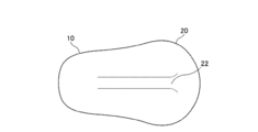
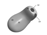
- FIG. 1 is a perspective view of a basic form of the outer ear wearing device of the present invention.
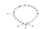
- FIG. 2 also shows the ventral side surface of the ear canal wearing device of FIG. 1 as viewed from the direction of the arrow on line II.
- FIG. 3 is a perspective view showing the outer ear wearing device of FIG. 1 applied to a hearing aid.
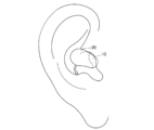
- FIG. 4 is a schematic view showing a state when the ear canal insertion portion of the ear canal fitting of FIG. 3 is inserted into the ear canal.
- FIG. 5 is a perspective view of the ear canal attachment of FIG. 3 as viewed from the direction of the arrow on the V line.
- FIG. 6 is a cross-sectional view of the concha cavity arrangement portion.
- FIG. 1 is a perspective view of a basic form of the outer ear wearing device of the present invention.
- FIG. 2 also shows the ventral side surface of the ear canal wearing device of FIG. 1 as viewed from the direction of the arrow on line II.
- FIG. 7 shows a state in which the external auditory canal insertion portion of the external ear canal fitting of FIG. 1 is inserted into the external auditory canal.
- FIG. 8 is a cross-sectional view showing a state of attachment between the ear canal and the ear canal insertion portion.
- FIG. 9 shows a state in which the ear canal insertion portion of the outer ear wearing tool of FIG. 1 is inserted into the ear canal and then rotated.
- FIG. 10 is a perspective view showing an example in which an outer ear fitting is applied to a vibrating hearing aid.
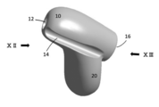
- FIG. 11 is a perspective view showing an example (for the left ear) in which the outer ear fitting is applied to another type of hearing aid, for example, the ear mold of the hearing aid.
- FIG. 12 is a perspective view taken along the line of the XII in FIG.
- FIG. 13 is a perspective view of the XIII arrow line of view in FIG.
- FIG. 1 shows the outer ear attachment 1 of the embodiment.
- the outer ear attachment 1 includes an ear canal insertion portion 10 and an ear canal cavity arrangement portion 20.
- the ear canal insertion portion 10 and the ear canal cavity arrangement portion 20 are arranged on the virtual spherical surface O shown by the alternate long and short dash line in the figure. More specifically, the ventral side surface (the surface on the side in contact with a person) of the external auditory canal insertion portion 10 and the concha cavity arrangement portion 20 may be arranged on the virtual spherical surface O.
- both the ear canal insertion portion 10 and the ear canal cavity arrangement portion 20 are formed in a tubular shape, it can be considered that their axes are arranged on a virtual spherical surface.
- the tubular shape is formed because a small speaker or the like may be housed inside them. Further, the weight is reduced by making it tubular, that is, hollow.
- the axes of the ear canal insertion portion 10 and the ear canal cavity arrangement portion 20 are preferably located on the same plane orthogonal to the tangent line of the virtual spherical surface in order to simplify the structure. As long as it is arranged on the virtual spherical surface as described above, it may be bent three-dimensionally.
- the outer ear fitting 1 can be made of a material harder than human tissue. Examples of such materials include resin materials such as methacrylic resin (acrylic), which is generally called thermoplastic, and excellent moldability and durability (chemical resistance, heat resistance, light resistance), and biocompatibility of stainless steel, titanium and the like. Examples of metal materials having excellent properties can be mentioned. It is preferable to mold using such a material. It can also be formed by laminated modeling. Examples of the soft material include silicone rubber and the like.
- the ear canal insertion portion 10 is a tubular member having an elliptical cross section.
- the major axis of the ellipse is the vertical direction. This is because, in general, the human ear canal is long in the vertical direction.
- the ear canal insertion portion 10 has a smaller diameter toward the tip side (see FIG. 2).
- the shape of the cross section is similar in the axial direction, but the shape of the cross section can be made irregular along the axial direction.
- the ear canal insertion portion 10 has a large diameter at its base end (that is, a connection portion with the ear canal cavity arrangement portion 20).
- An opening 12 can be formed on the ventral side of the tip of the ear canal insertion portion 10 (see FIG. 3). This opening 12 serves as an audio output portion.
- the sound output from the opening 12 reaches the eardrum directly in a state where the ear canal insertion portion 10 is inserted into the ear canal.
- the opening is in the center of the ear canal insertion portion 10 or on the dorsal side thereof, the probability that the sound output from the opening interferes with the peripheral wall of the ear canal before reaching the eardrum increases.
- a microphone hole 25 may be provided on the dorsal side of the concha cavity arrangement portion 20 (see FIG. 5).
- the parietal cavity arrangement portion 20 is integrally formed from the proximal end portion of the external auditory canal insertion portion 10.
- the parietal cavity arrangement portion 20 becomes wider as it is separated from the proximal end portion of the external auditory canal insertion portion 10. This is to ensure the stability of wearing by ensuring contact with the inner wall of the concha cavity.
- a ridge 22 is formed on the ventral side of the concha cavity arrangement portion 20.
- the height of the ridge 22 is not particularly limited, but is about 1 to 5 mm.
- the ridge 22 has a chevron-shaped cross section, and slightly concave slopes 22a and 22b are formed on both sides.
- the ridge 22 is continuously formed from the tip of the concha cavity arranging portion 20 to the connecting portion with the external auditory canal insertion portion 10.
- the outer ear fitting 1 thus formed inserts the ear canal insertion portion 10 into the human ear canal 100 so that its major axis (in the cross section) is in the vertical direction, as shown in FIG. 7, for example.
- the state of insertion is shown by a dotted line in FIG.
- the shape of the human ear canal varies widely, but in this example, since the major axis of the ear canal 100 (in the cross section) is longer than the major axis of the ear canal insertion section 10 (in the cross section), the ear canal insertion portion 10 is inserted into the ear canal 100. In this state, a random gap is formed between the ear canal 100 and the ear canal insertion portion 10.
- the external auditory canal insertion portion 10 when the external auditory canal insertion portion 10 is rotated counterclockwise (in the case of the right ear) from the state shown in FIG. 7, the external auditory canal insertion portion 10 comes into close contact with the anterior upper wall of the external auditory canal as shown by the solid line in FIG. .. Since the ear canal 100 is not a straight hole, in order to obtain close contact between the two, not only the ear canal insertion portion 10 is rotated about its axis, but also the ear canal insertion portion 10 is moved in the major axis direction thereof. Tilt at the same time. That is, it is necessary to rotate the whole three-dimensionally.
- both the ventral side surface of the external auditory canal insertion portion 10 and the ventral side surface of the parietal cavity arrangement portion 20 are arranged on the virtual spherical surface, the three-dimensional rotation is facilitated. Further, since the ridge 22 is formed on the ventral side surface of the concha cavity arrangement portion 20, when the external auditory canal insertion portion 10 is rotated around its long axis, both sides of the ridge 22 and the inner wall of the concha cavity are formed. Since a space is formed between the two and the ear canal cavity arrangement portion 20, the space is easily tilted using the space. As a result, the resistance to rotation of the ear canal insertion portion 10 is reduced.
- FIG. 9 shows an example of the final wearing state of the outer ear wearing tool 1.
- the external auditory canal insertion portion 10 is attached so as to follow the shape of the human ear, more specifically, the shape of the concha cavity-the entrance of the external auditory canal-the external auditory canal. Insert and rotate the tool 1 three-dimensionally while tilting it from time to time.
- the ear canal insertion portion 10 is in a state along the upper side wall of the ear canal 100 (see the solid line in FIG. 8).
- the base end portion (connecting portion with the concha cavity arrangement portion 20) of the external auditory canal insertion portion 10 having a relatively large diameter is sandwiched between the tragus and the posterior wall of the external auditory canal entrance, the external auditory canal insertion portion 10
- the rotation around the long axis and the movement in the long axis direction are restricted, and the position is stable.
- the concha cavity arranging portion 20 is designed to become wider from the connecting portion with the external auditory canal insertion portion 10 toward the posterior end, it is held and stabilized at at least one place in the concha cavity. It has become. Further, this limits the displacement of the ear canal insertion portion 10, and the inside of the ear canal is stably held by surface contact on the upper wall.
- the ridges 22 formed on the ventral side surface of the concha cavity arranging portion 20 improve the wearing feeling of the concha cavity arranging portion 20. This is because the contact area between the concha cavity arranging portion 20 and the inner wall of the concha cavity becomes small.
- FIG. 10 shows an example in which the outer ear fitting 10 is applied to a vibrating hearing aid.
- reference numeral 30 indicates a vibrating device
- reference numeral 40 indicates a connecting portion.
- the power supply line and signal line to the vibrating device 30 are drawn out via the connecting portion 40.
- FIG. 11 shows an example in which the outer ear fitting 10 is applied to the ear mold of a hearing aid.
- the groove 14 is formed by inflating the lower side surface of the ear canal insertion portion 10.
- the groove 14 acts as a vent to prevent the entire peripheral surface of the external auditory canal insertion portion 10 from coming into close contact with the human external auditory canal wall.
- the groove 14 is continuous from the tip of the ear canal insertion portion 10 toward the outside.
- FIG. 12 is a perspective view taken along the line of the XII in FIG.
- FIG. 13 is a perspective view of the XIII arrow line of view in FIG.
- Ear canal insertion part 10 Ear canal insertion part 12 Opening 14 Groove 16 Connection part 20
- Ear canal cavity arrangement part 22 Convex 22a Slightly concave slope 22b Slightly concave slope 25
- Microphone 30 Vibration device 40 Connection part 100 Ear canal O Virtual spherical surface
Abstract
装着感が優れて安定性の高いレディメイドの外耳装着具を提供する。 この発明の外耳装着具は、筒状の外耳道挿入部と耳甲介腔配置部とが仮想球状面上に配置され、筒状の外耳道挿入部は、外耳道に挿入された状態でその長軸を中心に回転可能とする。 外耳道挿入部に対して耳甲介腔配置部が同じ仮想球状面上に配置されているので、外耳道に外耳道挿入部を挿入した状態で、耳甲介腔配置部は耳甲介腔の内壁に沿った状態となる。従って、外耳道に挿入した状態の外耳道挿入部をその長軸を中心に回転させたり、その軸方向へ変位させたりする際に、耳甲介腔配置部が抵抗となることが極めて小さくなり、外耳道前上壁での面接触を実現する。その結果、様々な形態や大きさの外耳道に対して、上前壁での面接触と耳珠、耳甲介腔で保持されることにより高い安定性が得られる。さらに、耳甲介腔配置部の凸状形状によって不必要な密着を最小限に留め、外耳道下壁側では密着を避けることがベント効果となり装着感が優れている。
Description
本発明は、音響機器用の外耳装着具に関する。
従来、例えば補聴器、音声再生機器、音声通信機器、および環境対策機器(すなわちノイズキャンセラー)などの音響機器(聴覚機器)に用いられ、使用者の外耳道に挿入されて使用される外耳装着具が知られている。外耳道やそれに続く耳甲介腔の形状は個人差が大きいため、外耳装着具を外耳道に安定的に装着するには何らかの対策が必要である。
一人一人の外耳道や耳甲介腔を型取りすることで作成されるオーダーメイドの外耳装着具によれば、外耳道への装着状態が安定する。しかし、型取りする必要があるため、作成コストが高くなり、また作成期間が長くなるという別の問題が生じる。
一方、レディメイドの外耳装着具は、型取りする必要がないため、作成コストが比較的低くなり、また作成期間は不要である。いわゆる世間で広く販売されているイヤホンがそれにあたる。一方、補聴器においては、特許文献1に開示されたように外耳道を完全に閉鎖する密閉型のレディメイド品があり、オーダーメイド品と同様に装着状態が安定する。
本願発明に関係する先行技術を開示する文献として特許文献2も参照されたい。
本願発明に関係する先行技術を開示する文献として特許文献2も参照されたい。
特許文献1に記載の外耳装着具では、外耳道に挿入されるイヤチップが軟質な弾性材料で形成されているため、このイヤチップが外耳道に添って変形し、かつ反発力をもって外耳道の内周に押し当てられるので装着状態は安定しているように見える。しかしながら、オーダーメイド品と比較すると、外耳道内で位置が変り易い。外耳道内で外耳装着具の位置が変わると、鼓膜面での音圧が変化し、またハウリングも生じやすくなる。
特許文献2に記載の外耳装着具は比較的硬質な材料で形成されており、外耳道へ挿入される筒状の外耳道挿入部とこれに続く耳甲介腔配置部を備えている。かかる外耳装着具ではその外耳道挿入部がすべてのユーザの外耳道にフィットするわけではない。一般に筒状の外耳道挿入部は外耳道内においてこれを回転させたり、その位置を外耳道内で軸方向に移動させられたりすることで、外耳道に対するフィット感を高めることができる。しかしながら、この器具においては、外耳道挿入部に対して耳甲介腔配置部が固定されているので、耳甲介腔配置部が耳甲介腔の周壁に干渉して、外耳道挿入部の回転や移動を妨げることがある。
この発明は上記課題を解決すべくなされたものであり、第1の局面は次のように規定される。即ち、
筒状の外耳道挿入部と耳甲介腔配置部とが仮想球状面上に配置され、
筒状の外耳道挿入部は、外耳道に挿入された状態でその長軸を中心に回転可能である外耳装着具。
筒状の外耳道挿入部と耳甲介腔配置部とが仮想球状面上に配置され、
筒状の外耳道挿入部は、外耳道に挿入された状態でその長軸を中心に回転可能である外耳装着具。
このように規定される第1の局面の外耳装着具によれば、外耳道挿入部が筒状に形成されているので、この外耳道挿入部は外耳道に挿入された状態で長軸を中心に回転したり、外耳道内でその位置を長軸方向にずらしたり(変位)することができる。
ここに、外耳道挿入部に対して耳甲介腔配置部が同じ仮想球状面上に配置されているので、外耳道挿入部を外耳道に挿入した状態で、耳甲介腔配置部は耳甲介腔の内壁面に沿った状態となる。外耳道入口後壁-耳甲介腔の内壁が実質的に仮想球状面上に沿っているからである。ここでいう球状体とは真球に限られず、楕円球やその他の真球の変形体も該当する。
従って、外耳道に挿入した状態の外耳道挿入部をその長軸を中心に回転させたり、その軸方向へ変位させたりする際に、耳甲介腔配置部が抵抗となることが極めて小さくなる。
これにより、外耳道に対する外耳装着具の位置の調整が容易に、かつ大きな自由度をもって、行える。
ここに、外耳道挿入部に対して耳甲介腔配置部が同じ仮想球状面上に配置されているので、外耳道挿入部を外耳道に挿入した状態で、耳甲介腔配置部は耳甲介腔の内壁面に沿った状態となる。外耳道入口後壁-耳甲介腔の内壁が実質的に仮想球状面上に沿っているからである。ここでいう球状体とは真球に限られず、楕円球やその他の真球の変形体も該当する。
従って、外耳道に挿入した状態の外耳道挿入部をその長軸を中心に回転させたり、その軸方向へ変位させたりする際に、耳甲介腔配置部が抵抗となることが極めて小さくなる。
これにより、外耳道に対する外耳装着具の位置の調整が容易に、かつ大きな自由度をもって、行える。
この発明の第2の局面は次のように規定される。即ち、第1の局面に規定の外耳装着具において、外耳道挿入部を円筒状、若しくは楕円筒状とする。
外耳道挿入部を円筒状若しくは楕円筒状とすることにより、外耳道に挿入された状態で外耳道挿入部の、その長軸を中心とした回転が容易になる。
外耳道挿入部を円筒状とすることにより、外耳道内での回転が最も容易になる。
外耳道挿入部を楕円筒状とすることにより、これを回転させたとき外耳道の内周面に楕円の一部を密着させやすくなるので、その音響効果が安定する。また、密着した部分の反対側において外耳道の内周面との間に隙間をあけることができる。これにより、外耳道挿入部による外耳道の密閉による耳閉感を防止しやすい。
外耳道挿入部を円筒状若しくは楕円筒状とすることにより、外耳道に挿入された状態で外耳道挿入部の、その長軸を中心とした回転が容易になる。
外耳道挿入部を円筒状とすることにより、外耳道内での回転が最も容易になる。
外耳道挿入部を楕円筒状とすることにより、これを回転させたとき外耳道の内周面に楕円の一部を密着させやすくなるので、その音響効果が安定する。また、密着した部分の反対側において外耳道の内周面との間に隙間をあけることができる。これにより、外耳道挿入部による外耳道の密閉による耳閉感を防止しやすい。
この発明の第3の局面は次のように規定される。即ち、第1又は第2の局面に規定の外耳装着具において、外耳道挿入部の径はその先端から耳甲介腔配置部に向かって漸増する。
これにより、外耳道挿入部が外耳道に深く挿入されることを防止し、もって外耳道挿入部の適切な挿着状態が担保される。
外耳道挿入部の基端側、即ち耳甲介腔配置部との連結部分を大径とすることで、外耳装着具の挿着状態が安定する。即ち、当該連結部分において外耳道挿入部の背面側(ユーザからみて外側)は耳珠に接触し、他方その腹面側が外耳道入口後壁に接触する。当該連結部分を大径化しておくことで、この部分を耳珠と外耳道入口後壁との間で挟持させることができる。よって、外耳装着具の装着状態が安定する。
これにより、外耳道挿入部が外耳道に深く挿入されることを防止し、もって外耳道挿入部の適切な挿着状態が担保される。
外耳道挿入部の基端側、即ち耳甲介腔配置部との連結部分を大径とすることで、外耳装着具の挿着状態が安定する。即ち、当該連結部分において外耳道挿入部の背面側(ユーザからみて外側)は耳珠に接触し、他方その腹面側が外耳道入口後壁に接触する。当該連結部分を大径化しておくことで、この部分を耳珠と外耳道入口後壁との間で挟持させることができる。よって、外耳装着具の装着状態が安定する。
この発明の第4の局面は次のように規定される。即ち、第2又は第3の局面に規定の外耳装着具において、外耳道挿入部は断面楕円であり、楕円の長径は上下方向となる。
この明細書において、上下方向とは、外耳道挿入部を外耳道に挿入時における重力方向を指し、物理的に厳格な重力方向のみではなく、人による操作を考慮して、多少の傾きが含まれるものとする。
人の外耳道は一般的に縦長であるので、外耳道挿入部も縦長の楕円筒形とすることが好ましい。外耳道へ縦長楕円筒状の外耳道挿入部を挿入して、これを回転させることで、確実に外耳道挿入部を外耳道の上側面に沿わせて当てつけることができる。
この明細書において、上下方向とは、外耳道挿入部を外耳道に挿入時における重力方向を指し、物理的に厳格な重力方向のみではなく、人による操作を考慮して、多少の傾きが含まれるものとする。
人の外耳道は一般的に縦長であるので、外耳道挿入部も縦長の楕円筒形とすることが好ましい。外耳道へ縦長楕円筒状の外耳道挿入部を挿入して、これを回転させることで、確実に外耳道挿入部を外耳道の上側面に沿わせて当てつけることができる。
この発明の第5の局面は次のように規定される。即ち、第1~4のいずれかの局面に規定の外耳装着具において、耳甲介腔配置部は、外耳道挿入部の先端側からみたとき、外耳道挿入部より上下方向に幅広である。
耳甲介腔配置部を上下方向に幅広に形成することで、これを耳甲介腔により安定して装着できる。
耳甲介腔配置部を上下方向に幅広に形成することで、これを耳甲介腔により安定して装着できる。
この発明の第6の局面は次のように規定される。即ち、第1~5の局面に規定の外耳装着具において、耳甲介腔配置部の腹側面に凸条が形成されている。
かかる凸条により、耳甲介腔に対する耳甲介腔配置部の挿着感が向上する。凸条により耳甲介腔の内壁の生体組織に対して耳甲介腔配置部が線接触となり、接触面積が可及的に小さくなるからである。
また、この外耳装着具は、既述のように、耳珠と外耳道入口後壁で挟持されることがあるところ、この凸条が存在することにより、強く挟まれた状態においても、凸条の両脇と耳甲介腔の内壁との間に隙間ができる。この隙間が遊びとなって、外耳道挿入部がその長軸周りに回転する際、耳甲介腔配置部の可動性が向上する。即ち、外耳道挿入部の回転が円滑になる。
かかる凸条により、耳甲介腔に対する耳甲介腔配置部の挿着感が向上する。凸条により耳甲介腔の内壁の生体組織に対して耳甲介腔配置部が線接触となり、接触面積が可及的に小さくなるからである。
また、この外耳装着具は、既述のように、耳珠と外耳道入口後壁で挟持されることがあるところ、この凸条が存在することにより、強く挟まれた状態においても、凸条の両脇と耳甲介腔の内壁との間に隙間ができる。この隙間が遊びとなって、外耳道挿入部がその長軸周りに回転する際、耳甲介腔配置部の可動性が向上する。即ち、外耳道挿入部の回転が円滑になる。
この発明の第7の局面は次のように規定される。即ち、第1~6のいずれかの局面に規定の外耳装着具において、外耳道挿入部の先端に形成される音出力部は腹側に配置される。
これにより、鼓膜方向へ効率よく音波を導入することができる。
これにより、鼓膜方向へ効率よく音波を導入することができる。
この発明の第8の局面は次のように規定される。即ち、第1~7のいずれかの局面に規定の外耳装着具において、外耳道挿入部の下側の面に溝(ベント)が形成されている。
かかる溝を設けることで、外耳道挿入部によって外耳道が密閉状態になることを確実に防止できる。下側に溝を設けたのは、外耳道挿入部の上面を外耳道の上壁に当て付けるからである。
さらに、補聴器では上側にマイクが配置されるので、ベントは下側に形成して、マイクから離隔させることがハウリング予防に都合がよいからである。
かかる溝を設けることで、外耳道挿入部によって外耳道が密閉状態になることを確実に防止できる。下側に溝を設けたのは、外耳道挿入部の上面を外耳道の上壁に当て付けるからである。
さらに、補聴器では上側にマイクが配置されるので、ベントは下側に形成して、マイクから離隔させることがハウリング予防に都合がよいからである。
図1に実施例の外耳装着具1を示す。
この外耳装着具1は、外耳道挿入部10と耳甲介腔配置部20とを備えてなる。
外耳道挿入部10と耳甲介腔配置部20は、図中一点鎖線で示す、仮想球状面O上に配置されている。より詳しくは、外耳道挿入部10と耳甲介腔配置部20の腹側面(人と接触する側の面)が仮想球状面O上に配置されていればよい。かかる腹側面が球状面上に配置されることにより、外耳道挿入部を外耳道へ挿入した状態で、耳甲介腔配置部20を耳甲介腔に接触させながら、いわゆる三次元的な微調整が可能となる。
外耳道挿入部10及び耳甲介腔配置部20はともに筒状に形成されるので、その軸線が仮想球状面上に配置されるとみることもできる。ここに、筒状に形成されるのは、これらの内部に小型スピーカその他を収納させることがあるからである。また、筒状、即ち中空とすることで軽量化を図るためである。
外耳道挿入部10と耳甲介腔配置部20の各軸線は、構造をシンプルにするため、仮想球状面の接線に直交する同一平面上に存在することが好ましい。
既述のように仮想球状面上に配置されれば、3次元的に屈曲していてもよい。
この外耳装着具1は人の生体組織より硬質な材料で形成することができる。かかる材料として、熱可塑性プラスチックと総称されるメタクリル樹脂(アクリル)等の成形性がよくかつ耐久性(耐薬品性、耐熱性、耐光性)に優れた樹脂材料、ステンレススチール、チタン等の生体親和性に優れた金属材料を挙げることができる。かかる材料を用いて型成形することが好ましい。積層造形により形成することもできる。
軟質な材料としてはシリコーンゴム等が挙げられる。
外耳道挿入部10は断面楕円形の筒状部材である。楕円の長径は上下方向とされる。これば、一般的に人の外耳道は上下方向に長いからである。
外耳道挿入部10は先端側に行くにしたがって小径となる(図2参照)。この例では断面の形状は軸方向に相似性を保っているが、断面の形状を軸方向にそって異形とすることもできる。
外耳道挿入部10は、その基端(即ち、耳甲介腔配置部20との接続部)において径が大きくなる。
外耳道挿入部10の先端部は、その腹側に開口12を形成することができる(図3参照)この開口12が音声出力部となる。
開口12を腹側に設けることで、図4に示すように、外耳道挿入部10を外耳道へ挿入した状態で、その開口12から出力された音声は鼓膜へ直接到達する。他方、開口が外耳道挿入部10の中心やその背側にあると、開口から出力された音声が、鼓膜に到達する前に、外耳道の周壁と干渉する確率が高くなる。
耳甲介腔配置部20の背側にはマイク孔25を設けることもできる(図5参照)。
耳甲介腔配置部20は外耳道挿入部10の基端部から一体的に形成されている。耳甲介腔配置部20は、外耳道挿入部10の基端部から離れるにしたがって幅広になっている。耳甲介腔の内壁へ確実に接触するようにして、装着の安定性を確保するためである。
耳甲介腔配置部20の腹側には凸条22が形成されている。この凸条22の高さは特に限定されないが、1~5mm程度とする。この凸条22は、図6に示すように、断面山形であり、両サイドにわずかに凹形状の斜面22a、22bが形成されている。
凸条22は耳甲介腔配置部20の先端から外耳道挿入部10との連結部まで連続的に形成されている。
耳甲介腔配置部20の腹側には凸条22が形成されている。この凸条22の高さは特に限定されないが、1~5mm程度とする。この凸条22は、図6に示すように、断面山形であり、両サイドにわずかに凹形状の斜面22a、22bが形成されている。
凸条22は耳甲介腔配置部20の先端から外耳道挿入部10との連結部まで連続的に形成されている。
このように形成された外耳装着具1は、例えば、図7に示すように、外耳道挿入部10をその長径(断面における)が上下方向になるように、人の外耳道100へ挿入する。挿入の状態を図8に点線で示す。人の外耳道の形状は千差万別であるが、この例では、外耳道100の長径(断面における)が外耳道挿入部10の長径(断面における)より長いため、外耳道100へ外耳道挿入部10を挿入した状態では、外耳道100と外耳道挿入部10との間にランダムな隙間が形成されている。
そこで、図7に示す状態から、外耳道挿入部10を(右耳の場合)反時計回り方向へ回転させると、図8に実線で示す通り、外耳道挿入部10が外耳道の前上壁に密着する。
外耳道100は直線的な孔ではないので、このように両者の密着を得るには、外耳道挿入部10をその軸を中心に回転させることはもとより、外耳道挿入部10をその長軸方向に移動させ傾けることを同時に行う。即ち、全体を立体的に回転させる必要がある。
ここに、外耳道挿入部10の腹側面と耳甲介腔配置部20の腹側面とがともに仮想球状面上に配置されているので、上記立体的な回転が容易になる。
また、耳甲介腔配置部20の腹側面に凸条22が形成されているので、外耳道挿入部10をその長軸を中心に回転させたとき、凸条22両側と耳甲介腔の内壁との間に空間が形成されているので、当該空間を使って耳甲介腔配置部20が傾斜しやすくなる。これにより、外耳道挿入部10の回転に対する抵抗が低減化される。
図9に、外耳装着具1の最終装着状態の一例を示す。
図7の矢印で示す通り、外耳道挿入部10をその軸方向に回転させつつ、人の耳の形、より具体的には耳甲介腔-外耳道入口-外耳道の形状に沿うように、外耳装着具1を時に傾けながら三次元的に挿入回転させる。これにより、外耳道挿入部10は外耳道100の上側壁に沿った状態となる(図8の実線参照)。
この状態において、比較的大径な外耳道挿入部10の基端部(耳甲介腔配置部20との連結部)が耳珠と外耳道入口後壁とで挟持されているので、外耳道挿入部10の長軸を中心とした回転や、長軸方向への移動が規制され、位置が安定する。
更には、耳甲介腔配置部20は外耳道挿入部10との連結部から後端に向かうにつれ幅広となるように設計されているので、耳甲介腔の少なくとも一カ所で保持され安定するようになっている。また、これにより外耳道挿入部10の変位が制限され、外耳道内は上壁において面接触で安定保持されることになる。なお、耳甲介腔配置部20の腹側面に形成されている凸条22により耳甲介腔配置部20の装着感が向上している。耳甲介腔配置部20と耳甲介腔内壁との接触面積が小さくなるからである。
図10には外耳挿着具10を振動型補聴器に適用した例を示す。
図10において、符号30は振動装置、符号40は連結部を示す。振動装置30への電源線や信号線が連結部40を介して外部へ引き出される。
図11には外耳挿着具10を補聴器のイヤモールドに適用した例を示す。このイヤモールドでは、外耳道挿入部10の下側面を膨らませて溝14が形成されている。この溝14はベントの役割を奏し、外耳道挿入部10の全周面が人の外耳道壁に密着することを防止している。この溝14は外耳道挿入部10の先端から外側に向かって連続している。確実にベント作用を奏させ確実に耳閉感を防止するためである。符号16は補聴器本体との連結部である。
図12は図11におけるXII矢視線斜視図である。
図13は図11におけるXIII矢視線斜視図である。
この発明は、上記発明の実施形態の説明に何ら限定されるものではない。特許請求の範囲の記載を逸脱せず、当業者が容易に想到できる範囲で種々の変形態様もこの発明に含まれる。
1 外耳装着具
10 外耳道挿入部
12 開口
14 溝
16 連結部
20 耳甲介腔配置部
22 凸条
22aわずかに凹形状の斜面
22bわずかに凹形状の斜面
25 マイク
30 振動装置
40 連結部
100 外耳道
O 仮想球状面
10 外耳道挿入部
12 開口
14 溝
16 連結部
20 耳甲介腔配置部
22 凸条
22aわずかに凹形状の斜面
22bわずかに凹形状の斜面
25 マイク
30 振動装置
40 連結部
100 外耳道
O 仮想球状面
Claims (9)
- 筒状の外耳道挿入部と耳甲介腔配置部とが仮想球状面上に配置され、
筒状の外耳道挿入部は、外耳道に挿入された状態でその長軸を中心に回転可能である外耳装着具。 - 前記外耳道挿入部を円筒状、若しくは楕円筒状とする、請求項1に記載の外耳装着具。
- 前記外耳道挿入部の径はその先端から前記耳甲介腔配置部に向かって漸増する、請求項1又は2に記載の外耳装着具。
- 前記外耳道挿入部は断面楕円であり、楕円の長径は上下方向である、請求項2又は3に記載の外耳道挿着具。
- 前記耳甲介腔配置部は、前記外耳道挿入部の先端側からみたとき、前記外耳道挿入部より上下方向に幅広である、請求項1~4のいずれかに記載の外耳道挿着具。
- 前記耳甲介腔配置部の腹側面に凸条が形成されている、請求項1~5のいずれかに記載の外耳道装着具。
- 前記外耳道挿入部の先端に形成される音出力部は腹側に配置される、請求項1~6のいずれかに記載の外耳道装着具。
- 前記外耳道挿入部の下側の面を膨らませて溝が形成されている、請求項1~7のいずれかに記載の外耳道装着具。
- 筒状の外耳道挿入部と耳甲介腔配置部とを備え、
筒状の外耳道挿入部は、外耳道に挿入された状態でその長軸を中心に回転可能である外耳装着具であって、
前記外耳道挿入部の先端に形成される音出力部は腹側に配置される、外耳装着具。
Priority Applications (3)
| Application Number | Priority Date | Filing Date | Title |
|---|---|---|---|
| JP2021553697A JPWO2021085559A1 (ja) | 2019-10-30 | 2020-10-29 | |
| EP20881723.9A EP4054203A4 (en) | 2019-10-30 | 2020-10-29 | DEVICE TO BE WEAR ON THE OUTER EAR |
| US17/770,819 US20220377477A1 (en) | 2019-10-30 | 2020-10-29 | Implement to be worn on outer ear |
Applications Claiming Priority (2)
| Application Number | Priority Date | Filing Date | Title |
|---|---|---|---|
| JP2019-197472 | 2019-10-30 | ||
| JP2019197472 | 2019-10-30 |
Publications (1)
| Publication Number | Publication Date |
|---|---|
| WO2021085559A1 true WO2021085559A1 (ja) | 2021-05-06 |
Family
ID=75715177
Family Applications (1)
| Application Number | Title | Priority Date | Filing Date |
|---|---|---|---|
| PCT/JP2020/040698 WO2021085559A1 (ja) | 2019-10-30 | 2020-10-29 | 外耳装着具 |
Country Status (4)
| Country | Link |
|---|---|
| US (1) | US20220377477A1 (ja) |
| EP (1) | EP4054203A4 (ja) |
| JP (1) | JPWO2021085559A1 (ja) |
| WO (1) | WO2021085559A1 (ja) |
Families Citing this family (1)
| Publication number | Priority date | Publication date | Assignee | Title |
|---|---|---|---|---|
| US11877110B2 (en) * | 2022-01-13 | 2024-01-16 | Bose Corporation | Flow relief features embedded in cosmetic surface of wearables |
Citations (15)
| Publication number | Priority date | Publication date | Assignee | Title |
|---|---|---|---|---|
| JPS5518825U (ja) * | 1978-07-20 | 1980-02-06 | ||
| US4311206A (en) * | 1978-05-15 | 1982-01-19 | Johnson Rubein V | Hearing aid ear mold with improved discrimination |
| JPH03117999A (ja) * | 1989-09-30 | 1991-05-20 | Sony Corp | 電気音響変換器及び音響再生システム |
| JPH06113001A (ja) * | 1992-02-24 | 1994-04-22 | Pilot Corp:The | 片耳装着型送受話器 |
| JPH0644504U (ja) * | 1992-11-21 | 1994-06-14 | 株式会社堀場製作所 | 耳式体温計 |
| JPH08195999A (ja) * | 1995-01-17 | 1996-07-30 | Rion Co Ltd | 耳穴装用具 |
| JP2684812B2 (ja) | 1990-03-27 | 1997-12-03 | リオン 株式会社 | 挿耳形補聴器 |
| JPH10126873A (ja) * | 1996-10-21 | 1998-05-15 | Matsushita Electric Ind Co Ltd | 骨振動型マイクロホンおよび振動ピックアップ |
| JP2012525799A (ja) * | 2009-04-30 | 2012-10-22 | ヴェルト メディカル ソリューションズ、エルエルシー | イヤホンシステム |
| JP2012222682A (ja) * | 2011-04-12 | 2012-11-12 | Tetsuhiro Tanaka | 骨伝導イヤホン |
| JP2013058880A (ja) * | 2011-09-08 | 2013-03-28 | Rion Co Ltd | 既製耳あな型補聴器 |
| JP2014508553A (ja) * | 2010-12-16 | 2014-04-10 | サイオン・ニューロスティム,リミテッド・ライアビリティ・カンパニー | 医師による監視下で患者に神経刺激を送達するためのシステム、方法及び装置 |
| JP2015521424A (ja) * | 2012-05-11 | 2015-07-27 | ハーマン インターナショナル インダストリーズ インコーポレイテッド | 生理学的センサ付きのイヤホン及び小型イヤホン |
| JP2017139649A (ja) | 2016-02-04 | 2017-08-10 | パナソニックIpマネジメント株式会社 | 補聴器及びイヤーチップ |
| JP2018098596A (ja) * | 2016-12-12 | 2018-06-21 | リオン株式会社 | 耳あな型補聴器 |
Family Cites Families (7)
| Publication number | Priority date | Publication date | Assignee | Title |
|---|---|---|---|---|
| DE8518681U1 (de) * | 1985-06-27 | 1986-06-12 | Siemens AG, 1000 Berlin und 8000 München | Hörhilfe |
| US7014010B2 (en) * | 2000-06-30 | 2006-03-21 | Phonak Ag | Method for manufacturing an ear device and ear device |
| US7394909B1 (en) * | 2000-09-25 | 2008-07-01 | Phonak Ag | Hearing device with embedded channnel |
| US9479859B2 (en) * | 2013-11-18 | 2016-10-25 | 3M Innovative Properties Company | Concha-fit electronic hearing protection device |
| EP3248394A4 (en) * | 2015-01-19 | 2018-09-12 | 3M Innovative Properties Company | Hearing protection device with convoluted acoustic horn |
| WO2017183027A1 (en) * | 2016-04-17 | 2017-10-26 | Lifebeam Technologies Ltd. | Earbud with physiological sensor and stabilizing element |
| EP3780647A4 (en) * | 2018-03-26 | 2021-05-05 | Sony Corporation | ACOUSTIC OUTPUT DEVICE |
-
2020
- 2020-10-29 US US17/770,819 patent/US20220377477A1/en active Pending
- 2020-10-29 EP EP20881723.9A patent/EP4054203A4/en active Pending
- 2020-10-29 JP JP2021553697A patent/JPWO2021085559A1/ja active Pending
- 2020-10-29 WO PCT/JP2020/040698 patent/WO2021085559A1/ja active Search and Examination
Patent Citations (15)
| Publication number | Priority date | Publication date | Assignee | Title |
|---|---|---|---|---|
| US4311206A (en) * | 1978-05-15 | 1982-01-19 | Johnson Rubein V | Hearing aid ear mold with improved discrimination |
| JPS5518825U (ja) * | 1978-07-20 | 1980-02-06 | ||
| JPH03117999A (ja) * | 1989-09-30 | 1991-05-20 | Sony Corp | 電気音響変換器及び音響再生システム |
| JP2684812B2 (ja) | 1990-03-27 | 1997-12-03 | リオン 株式会社 | 挿耳形補聴器 |
| JPH06113001A (ja) * | 1992-02-24 | 1994-04-22 | Pilot Corp:The | 片耳装着型送受話器 |
| JPH0644504U (ja) * | 1992-11-21 | 1994-06-14 | 株式会社堀場製作所 | 耳式体温計 |
| JPH08195999A (ja) * | 1995-01-17 | 1996-07-30 | Rion Co Ltd | 耳穴装用具 |
| JPH10126873A (ja) * | 1996-10-21 | 1998-05-15 | Matsushita Electric Ind Co Ltd | 骨振動型マイクロホンおよび振動ピックアップ |
| JP2012525799A (ja) * | 2009-04-30 | 2012-10-22 | ヴェルト メディカル ソリューションズ、エルエルシー | イヤホンシステム |
| JP2014508553A (ja) * | 2010-12-16 | 2014-04-10 | サイオン・ニューロスティム,リミテッド・ライアビリティ・カンパニー | 医師による監視下で患者に神経刺激を送達するためのシステム、方法及び装置 |
| JP2012222682A (ja) * | 2011-04-12 | 2012-11-12 | Tetsuhiro Tanaka | 骨伝導イヤホン |
| JP2013058880A (ja) * | 2011-09-08 | 2013-03-28 | Rion Co Ltd | 既製耳あな型補聴器 |
| JP2015521424A (ja) * | 2012-05-11 | 2015-07-27 | ハーマン インターナショナル インダストリーズ インコーポレイテッド | 生理学的センサ付きのイヤホン及び小型イヤホン |
| JP2017139649A (ja) | 2016-02-04 | 2017-08-10 | パナソニックIpマネジメント株式会社 | 補聴器及びイヤーチップ |
| JP2018098596A (ja) * | 2016-12-12 | 2018-06-21 | リオン株式会社 | 耳あな型補聴器 |
Non-Patent Citations (1)
| Title |
|---|
| See also references of EP4054203A4 |
Also Published As
| Publication number | Publication date |
|---|---|
| EP4054203A1 (en) | 2022-09-07 |
| JPWO2021085559A1 (ja) | 2021-05-06 |
| US20220377477A1 (en) | 2022-11-24 |
| EP4054203A4 (en) | 2024-01-17 |
Similar Documents
| Publication | Publication Date | Title |
|---|---|---|
| US9955249B2 (en) | Earpiece with movable joint | |
| US10009680B2 (en) | Retaining structure for an earpiece | |
| US7627131B2 (en) | Flexible earpiece for a hearing aid | |
| JP6037483B2 (ja) | イヤーピースパッシブノイズ減衰 | |
| JP7447933B2 (ja) | イヤホン及びサポータ | |
| US7720242B2 (en) | Flexible joint for extended wear hearing device | |
| US10820084B2 (en) | Ear tip sealing structure | |
| US8503707B2 (en) | Sealing retainer for extended wear hearing devices | |
| US5298692A (en) | Earpiece for insertion in an ear canal, and an earphone, microphone, and earphone/microphone combination comprising the same | |
| KR101742333B1 (ko) | 이어피스 시스템 | |
| US11917351B2 (en) | Audio device | |
| US10924842B2 (en) | Audio device | |
| US11381897B2 (en) | Variable eartip for earphone | |
| JPS61238198A (ja) | カスタム挿耳型補聴器 | |
| JP2023509594A (ja) | 開放型オーディオデバイス | |
| EP3646614A1 (en) | Customized eartips | |
| WO2021085559A1 (ja) | 外耳装着具 | |
| EP3334179B1 (en) | Hearing aid with an extended dome | |
| US20180103310A1 (en) | Light weight headphone | |
| KR20040094406A (ko) | 보청기 |
Legal Events
| Date | Code | Title | Description |
|---|---|---|---|
| 121 | Ep: the epo has been informed by wipo that ep was designated in this application |
Ref document number: 20881723 Country of ref document: EP Kind code of ref document: A1 |
|
| DPE1 | Request for preliminary examination filed after expiration of 19th month from priority date (pct application filed from 20040101) | ||
| ENP | Entry into the national phase |
Ref document number: 2021553697 Country of ref document: JP Kind code of ref document: A |
|
| NENP | Non-entry into the national phase |
Ref country code: DE |
|
| ENP | Entry into the national phase |
Ref document number: 2020881723 Country of ref document: EP Effective date: 20220530 |