WO2021085247A1 - 撮像支援装置、撮像装置、撮像システム、撮像支援システム、撮像支援方法、及びプログラム - Google Patents
撮像支援装置、撮像装置、撮像システム、撮像支援システム、撮像支援方法、及びプログラム Download PDFInfo
- Publication number
- WO2021085247A1 WO2021085247A1 PCT/JP2020/039425 JP2020039425W WO2021085247A1 WO 2021085247 A1 WO2021085247 A1 WO 2021085247A1 JP 2020039425 W JP2020039425 W JP 2020039425W WO 2021085247 A1 WO2021085247 A1 WO 2021085247A1
- Authority
- WO
- WIPO (PCT)
- Prior art keywords
- image
- target subject
- amount
- imaging
- runout
- Prior art date
- Legal status (The legal status is an assumption and is not a legal conclusion. Google has not performed a legal analysis and makes no representation as to the accuracy of the status listed.)
- Ceased
Links
Images








Classifications
-
- F—MECHANICAL ENGINEERING; LIGHTING; HEATING; WEAPONS; BLASTING
- F16—ENGINEERING ELEMENTS AND UNITS; GENERAL MEASURES FOR PRODUCING AND MAINTAINING EFFECTIVE FUNCTIONING OF MACHINES OR INSTALLATIONS; THERMAL INSULATION IN GENERAL
- F16M—FRAMES, CASINGS OR BEDS OF ENGINES, MACHINES OR APPARATUS, NOT SPECIFIC TO ENGINES, MACHINES OR APPARATUS PROVIDED FOR ELSEWHERE; STANDS; SUPPORTS
- F16M11/00—Stands or trestles as supports for apparatus or articles placed thereon ; Stands for scientific apparatus such as gravitational force meters
- F16M11/02—Heads
- F16M11/04—Means for attachment of apparatus; Means allowing adjustment of the apparatus relatively to the stand
- F16M11/06—Means for attachment of apparatus; Means allowing adjustment of the apparatus relatively to the stand allowing pivoting
- F16M11/10—Means for attachment of apparatus; Means allowing adjustment of the apparatus relatively to the stand allowing pivoting around a horizontal axis
-
- H—ELECTRICITY
- H04—ELECTRIC COMMUNICATION TECHNIQUE
- H04N—PICTORIAL COMMUNICATION, e.g. TELEVISION
- H04N23/00—Cameras or camera modules comprising electronic image sensors; Control thereof
- H04N23/60—Control of cameras or camera modules
- H04N23/67—Focus control based on electronic image sensor signals
-
- F—MECHANICAL ENGINEERING; LIGHTING; HEATING; WEAPONS; BLASTING
- F16—ENGINEERING ELEMENTS AND UNITS; GENERAL MEASURES FOR PRODUCING AND MAINTAINING EFFECTIVE FUNCTIONING OF MACHINES OR INSTALLATIONS; THERMAL INSULATION IN GENERAL
- F16M—FRAMES, CASINGS OR BEDS OF ENGINES, MACHINES OR APPARATUS, NOT SPECIFIC TO ENGINES, MACHINES OR APPARATUS PROVIDED FOR ELSEWHERE; STANDS; SUPPORTS
- F16M11/00—Stands or trestles as supports for apparatus or articles placed thereon ; Stands for scientific apparatus such as gravitational force meters
- F16M11/02—Heads
- F16M11/18—Heads with mechanism for moving the apparatus relatively to the stand
-
- F—MECHANICAL ENGINEERING; LIGHTING; HEATING; WEAPONS; BLASTING
- F16—ENGINEERING ELEMENTS AND UNITS; GENERAL MEASURES FOR PRODUCING AND MAINTAINING EFFECTIVE FUNCTIONING OF MACHINES OR INSTALLATIONS; THERMAL INSULATION IN GENERAL
- F16M—FRAMES, CASINGS OR BEDS OF ENGINES, MACHINES OR APPARATUS, NOT SPECIFIC TO ENGINES, MACHINES OR APPARATUS PROVIDED FOR ELSEWHERE; STANDS; SUPPORTS
- F16M11/00—Stands or trestles as supports for apparatus or articles placed thereon ; Stands for scientific apparatus such as gravitational force meters
- F16M11/20—Undercarriages with or without wheels
- F16M11/2007—Undercarriages with or without wheels comprising means allowing pivoting adjustment
- F16M11/2014—Undercarriages with or without wheels comprising means allowing pivoting adjustment around a vertical axis
-
- F—MECHANICAL ENGINEERING; LIGHTING; HEATING; WEAPONS; BLASTING
- F16—ENGINEERING ELEMENTS AND UNITS; GENERAL MEASURES FOR PRODUCING AND MAINTAINING EFFECTIVE FUNCTIONING OF MACHINES OR INSTALLATIONS; THERMAL INSULATION IN GENERAL
- F16M—FRAMES, CASINGS OR BEDS OF ENGINES, MACHINES OR APPARATUS, NOT SPECIFIC TO ENGINES, MACHINES OR APPARATUS PROVIDED FOR ELSEWHERE; STANDS; SUPPORTS
- F16M13/00—Other supports for positioning apparatus or articles; Means for steadying hand-held apparatus or articles
- F16M13/02—Other supports for positioning apparatus or articles; Means for steadying hand-held apparatus or articles for supporting on, or attaching to, an object, e.g. tree, gate, window-frame, cycle
-
- G—PHYSICS
- G03—PHOTOGRAPHY; CINEMATOGRAPHY; ANALOGOUS TECHNIQUES USING WAVES OTHER THAN OPTICAL WAVES; ELECTROGRAPHY; HOLOGRAPHY
- G03B—APPARATUS OR ARRANGEMENTS FOR TAKING PHOTOGRAPHS OR FOR PROJECTING OR VIEWING THEM; APPARATUS OR ARRANGEMENTS EMPLOYING ANALOGOUS TECHNIQUES USING WAVES OTHER THAN OPTICAL WAVES; ACCESSORIES THEREFOR
- G03B15/00—Special procedures for taking photographs; Apparatus therefor
-
- G—PHYSICS
- G03—PHOTOGRAPHY; CINEMATOGRAPHY; ANALOGOUS TECHNIQUES USING WAVES OTHER THAN OPTICAL WAVES; ELECTROGRAPHY; HOLOGRAPHY
- G03B—APPARATUS OR ARRANGEMENTS FOR TAKING PHOTOGRAPHS OR FOR PROJECTING OR VIEWING THEM; APPARATUS OR ARRANGEMENTS EMPLOYING ANALOGOUS TECHNIQUES USING WAVES OTHER THAN OPTICAL WAVES; ACCESSORIES THEREFOR
- G03B17/00—Details of cameras or camera bodies; Accessories therefor
- G03B17/56—Accessories
-
- G—PHYSICS
- G03—PHOTOGRAPHY; CINEMATOGRAPHY; ANALOGOUS TECHNIQUES USING WAVES OTHER THAN OPTICAL WAVES; ELECTROGRAPHY; HOLOGRAPHY
- G03B—APPARATUS OR ARRANGEMENTS FOR TAKING PHOTOGRAPHS OR FOR PROJECTING OR VIEWING THEM; APPARATUS OR ARRANGEMENTS EMPLOYING ANALOGOUS TECHNIQUES USING WAVES OTHER THAN OPTICAL WAVES; ACCESSORIES THEREFOR
- G03B17/00—Details of cameras or camera bodies; Accessories therefor
- G03B17/56—Accessories
- G03B17/561—Support related camera accessories
-
- G—PHYSICS
- G03—PHOTOGRAPHY; CINEMATOGRAPHY; ANALOGOUS TECHNIQUES USING WAVES OTHER THAN OPTICAL WAVES; ELECTROGRAPHY; HOLOGRAPHY
- G03B—APPARATUS OR ARRANGEMENTS FOR TAKING PHOTOGRAPHS OR FOR PROJECTING OR VIEWING THEM; APPARATUS OR ARRANGEMENTS EMPLOYING ANALOGOUS TECHNIQUES USING WAVES OTHER THAN OPTICAL WAVES; ACCESSORIES THEREFOR
- G03B5/00—Adjustment of optical system relative to image or object surface other than for focusing
-
- H—ELECTRICITY
- H04—ELECTRIC COMMUNICATION TECHNIQUE
- H04N—PICTORIAL COMMUNICATION, e.g. TELEVISION
- H04N23/00—Cameras or camera modules comprising electronic image sensors; Control thereof
- H04N23/60—Control of cameras or camera modules
- H04N23/68—Control of cameras or camera modules for stable pick-up of the scene, e.g. compensating for camera body vibrations
- H04N23/681—Motion detection
- H04N23/6811—Motion detection based on the image signal
-
- H—ELECTRICITY
- H04—ELECTRIC COMMUNICATION TECHNIQUE
- H04N—PICTORIAL COMMUNICATION, e.g. TELEVISION
- H04N23/00—Cameras or camera modules comprising electronic image sensors; Control thereof
- H04N23/60—Control of cameras or camera modules
- H04N23/68—Control of cameras or camera modules for stable pick-up of the scene, e.g. compensating for camera body vibrations
- H04N23/682—Vibration or motion blur correction
- H04N23/685—Vibration or motion blur correction performed by mechanical compensation
-
- H—ELECTRICITY
- H04—ELECTRIC COMMUNICATION TECHNIQUE
- H04N—PICTORIAL COMMUNICATION, e.g. TELEVISION
- H04N23/00—Cameras or camera modules comprising electronic image sensors; Control thereof
- H04N23/60—Control of cameras or camera modules
- H04N23/68—Control of cameras or camera modules for stable pick-up of the scene, e.g. compensating for camera body vibrations
- H04N23/682—Vibration or motion blur correction
- H04N23/685—Vibration or motion blur correction performed by mechanical compensation
- H04N23/687—Vibration or motion blur correction performed by mechanical compensation by shifting the lens or sensor position
-
- H—ELECTRICITY
- H04—ELECTRIC COMMUNICATION TECHNIQUE
- H04N—PICTORIAL COMMUNICATION, e.g. TELEVISION
- H04N23/00—Cameras or camera modules comprising electronic image sensors; Control thereof
- H04N23/60—Control of cameras or camera modules
- H04N23/695—Control of camera direction for changing a field of view, e.g. pan, tilt or based on tracking of objects
Definitions
- the present disclosure relates to an imaging support device, an imaging device, an imaging system, an imaging support system, an imaging support method, and a program.
- Japanese Patent Application Laid-Open No. 2017-215350 describes an output means for outputting a shake detection signal related to a shake of an apparatus, a detection means for detecting a subject from a captured image, a notification means for notifying a shooting state, and a detected subject.
- a control means for performing tracking and image shake correction of a subject by using a correction means based on a tracking target position and a shake detection signal is provided, and the control means tracks and an image of the subject according to a shooting state.
- An image shake correction device is disclosed, which determines which of the runout corrections is prioritized to be executed.
- Japanese Unexamined Patent Publication No. 2017-126960 describes a position detecting means for detecting the position of a subject in the screen, a speed detecting means for detecting the speed of the subject by using the amount of movement of the position of the subject in the screen, and continuous shooting.
- An image shake correction device including a tracking amount calculating means for calculating a tracking amount, which is an amount, and a control means for driving a shift means based on the tracking amount are disclosed.
- Japanese Unexamined Patent Publication No. 2017-06334 is an image shake correction device that corrects image shake using a shake correction means based on a shake detection signal, and is an acquisition means for acquiring subject information about a subject detected from a captured image.
- An image shake correction device characterized in that the reference position of the subject within the shooting angle of view is set based on the subject information, and the control means for controlling the shake correction means is provided so that the subject moves toward the reference position. Is disclosed.
- One embodiment according to the technique of the present disclosure is an imaging support device, an imaging device, an imaging system, an imaging support system, an imaging support method that can support tracking of a target subject when imaging an imaging region including the target subject. , And provide a program.
- the first aspect according to the technique of the present disclosure is an image pickup support device that supports image pickup by an image pickup device including an image pickup element, and an image pickup image obtained by capturing an image pickup region including a target subject by the image pickup device.
- An acquisition unit that acquires the amount of in-image deviation between the default position and the position of the target subject image indicating the target subject, and the focal distance of the image sensor, and a position adjustment unit that adjusts the position of the target subject image in the captured image.
- the position adjusting unit is equipped with an image pickup device, has a swivel mechanism capable of turning the image pickup device, and a runout that corrects runout caused by vibration given to the image pickup device. Further, a control unit having a correction unit and performing adjustment control for adjusting the position of the target subject image in the captured image by operating at least one of the swivel mechanism and the runout correction unit based on the amount of movement. It is an image pickup support device which concerns on the 1st aspect which concerns on this disclosure technique including.
- the movement amount is the first movement amount required for adjusting the position of the target subject image by the turning mechanism and the second movement required for adjusting the position of the target subject image by the shake correction unit. It is an image pickup support device which concerns on the 2nd aspect which concerns on the technique of this disclosure which is determined based on the quantity.
- the shake correction unit has a shake correction element which is at least one of a lens and an image pickup element that corrects shake by moving in response to vibration, and at a specific position.
- the shake correction element is an image pickup support device according to a second aspect or a third aspect according to the technique of the present disclosure, which is located at the center of the movable range of the shake correction element.
- the acquisition unit further acquires the sensitivity of the runout correction unit
- the derivation unit is the amount of deviation of the runout correction element between the center position of the movable range and the current position of the runout correction element.
- the amount of movement of the shake correction element required to move the current position to the center position is derived as the second amount of movement required to adjust the position of the target subject image by the shake correction unit. It is an image pickup support device which concerns on the 4th aspect which concerns on the disclosed technology.
- a sixth aspect according to the technique of the present disclosure is that the first movement amount is determined based on a value obtained by dividing the product of the amount of in-image deviation and the pixel spacing by the focal length from the third aspect according to the technique of the present disclosure.
- An image pickup support device according to any one of the fifth aspects.
- the movement amount is obtained by combining the first movement amount and the second movement amount derived by the out-licensing unit, and the third aspect to the sixth aspect of the technique of the present disclosure is obtained.
- This is an imaging support device according to any one of the above aspects.
- the eighth aspect according to the technique of the present disclosure is any of the second to seventh aspects according to the technique of the present disclosure, wherein the control unit performs the vibration correction by the shake correction unit and the adjustment control in a time division manner.
- This is an imaging support device according to one of them.
- control unit causes the shake correction unit to correct the shake while the image pickup device is swiveled by the swivel mechanism, and the swivel mechanism stops the swivel of the image pickup device.
- a tenth aspect of the technique of the present disclosure is that the adjustment control is a control in which the position of the target subject image is adjusted by the turning mechanism and then the position of the target subject image is adjusted by the shake correction unit.
- the image pickup support device according to the eighth aspect or the ninth aspect according to the technique of the above.
- the eleventh aspect according to the technique of the present disclosure is that the swivel mechanism is a biaxial swivel mechanism capable of swiveling the imaging device in the first direction and the second direction intersecting the first direction, and the shake correction unit is ,
- An imaging support device according to any one of the second to tenth aspects of the technique of the present disclosure, which is at least one of an optical runout correction mechanism and an electronic runout correction unit.
- a twelfth aspect according to the technique of the present disclosure is the eleventh aspect of the technique of the present disclosure, wherein the optical shake correction mechanism is at least one of a lens moving shake correction mechanism and an image sensor moving shake correction mechanism.
- This is an image pickup support device according to the above aspect.
- a thirteenth aspect according to the technique of the present disclosure is an imaging support device according to any one of the first to twelfth aspects of the technique of the present disclosure, wherein the acquisition unit further acquires information on the pixel spacing. is there.
- a fourteenth aspect according to the technique of the present disclosure is an imaging support device according to any one of the first to thirteenth aspects of the technique of the present disclosure, wherein the output unit outputs a moving amount to the outside. ..
- the amount of movement is determined based on the moving speed of the target subject when the target subject is moving, from the first aspect to the fourteenth aspect of the technique of the present disclosure. It is an image pickup support device which concerns on any one of.
- the sixteenth aspect according to the technique of the present disclosure is the imaging support device according to the fifteenth aspect according to the technique of the present disclosure, wherein the moving speed is a plurality of speeds obtained by being decomposed in a plurality of different directions. is there.
- a seventeenth aspect according to the technique of the present disclosure includes an image pickup support device and an image pickup element according to any one of the first to sixteenth aspects according to the technique of the present disclosure, and the image pickup device includes an image pickup device.
- the eighteenth aspect according to the technique of the present disclosure reflects the adjustment result of the position of the target subject image based on the image pickup apparatus according to the seventeenth aspect according to the technique of the present disclosure and the movement amount derived by the extraction unit.
- the imaging system includes a control device that controls at least one of a control for displaying the image on the display unit and a control for storing the image data indicating the image on which the adjustment result is reflected on the storage unit. ..
- a nineteenth aspect according to the technique of the present disclosure is an image pickup support device that supports image pickup by an image pickup device including an image pickup element, and is an image captured image obtained by capturing an image pickup region including a target subject by the image pickup device.
- An acquisition unit that acquires the amount of in-image deviation between the default position and the position of the target subject image indicating the target subject, and the focal distance of the image sensor, and a position adjustment unit that adjusts the position of the target subject image in the captured image.
- the position adjustment unit includes a derivation unit that derives the image based on the above and an output unit that outputs the movement amount derived by the derivation unit. It has a runout correction unit that corrects runout caused by given vibration, and operates at least one of the turning mechanism and the runout correction unit based on the amount of movement to obtain a target subject image in the captured image. It is an image pickup system including an image pickup support device further including a control unit that performs adjustment control for adjusting the position of the image sensor, and an image pickup element.
- a twentieth aspect according to the technique of the present disclosure includes an image pickup support device according to any one of the first to sixteenth aspects according to the technique of the present disclosure, a position adjusting unit, and an image pickup support device.
- the derivation unit included in is an imaging support system that derives the amount of movement.
- a 21st aspect according to the technique of the present disclosure is an image pickup support method for supporting an image pickup by an image pickup device including an image pickup element, and an image pickup image obtained by capturing an image pickup region including a target subject by the image pickup element.
- the target subject image is obtained by acquiring the amount of deviation in the image and the focal distance between the predetermined position in the image and the position of the target subject image indicating the target subject, and by adjusting the position of the target subject image in the captured image.
- the amount of movement required to move the position to a specific position is derived based on the acquired amount of in-image deviation, the acquired focal distance, and the pixel spacing of the pixels of the image sensor, and the derived amount of movement is output. It is an image pickup support method including the above.
- the 22nd aspect according to the technique of the present disclosure is a program for causing a computer to execute a process of supporting an image pickup by an image pickup device including an image pickup element, and the process is such that an image pickup region including a target subject is formed by the image pickup element.
- the amount of movement required to move the position of the target subject image to a specific position by the position adjusting unit to be adjusted is derived based on the acquired amount of in-image deviation, the acquired focal distance, and the pixel spacing of the pixels of the image sensor.
- CPU is an abbreviation for "Central Processing Unit”.
- GPU is an abbreviation for "Graphics Processing Unit”.
- ASIC is an abbreviation for "Application Specific Integrated Circuit”.
- PLD is an abbreviation for "Programmable Logic Device”.
- FPGA is an abbreviation for "Field-Programmable Gate Array”.
- AFE is an abbreviation for "Analog Front End”.
- DSP is an abbreviation for "Digital Signal Processor”.
- SoC is an abbreviation for "System-on-a-chip”.
- SSD is an abbreviation for "Solid State Drive”.
- USB is an abbreviation for "Universal Serial Bus”.
- HDD is an abbreviation for "Hard Disk Drive”.
- EEPROM is an abbreviation for "Electrically Erasable and Programmable Read Only Memory”.
- EL is an abbreviation for "Electro-Luminescence”.
- a / D is an abbreviation for "Analog / Digital”.
- I / F is an abbreviation for "Interface”.
- UI is an abbreviation for "User Interface”.
- WAN is an abbreviation for "Wide Area Network”.
- ISP is an abbreviation for "Image Signal Processor”.
- CMOS is an abbreviation for "Complementary Metal Oxide Semiconductor”.
- CCD is an abbreviation for "Charge Coupled Device”.
- SWIR is an abbreviation for "Short-wavelength infrared”.
- vertical refers to vertical in the sense of including an error generally allowed in the technical field to which the technology of the present disclosure belongs, in addition to the complete vertical.
- horizontal refers to horizontal in the sense of being perfectly horizontal, as well as including errors that are generally tolerated in the art to which the technology of the present disclosure belongs.
- parallel refers to parallelism in the sense that it includes, in addition to perfect parallelism, errors that are generally acceptable in the art to which the techniques of the present disclosure belong.
- vertical refers to vertical in the sense of being perfectly vertical, as well as including errors that are generally tolerated in the art to which the technology of the present disclosure belongs.
- the term “identical” refers to the exact same, as well as the same in the sense that it includes errors that are generally tolerated in the technical field to which the technology of the present disclosure belongs.
- the surveillance system 2 includes a surveillance camera 10 and a management device 11.
- the surveillance system 2 is an example of the "imaging system” and the “imaging support system” according to the technology of the present disclosure
- the surveillance camera 10 is an example of the "imaging apparatus” according to the technology of the present disclosure.
- the surveillance camera 10 is installed on a pillar, wall, part of a building (for example, a rooftop) indoors or outdoors via a swivel mechanism 16 described later, and images a surveillance object as a subject to obtain a moving image. To generate.
- the moving image includes a multi-frame image obtained by imaging.
- the surveillance camera 10 transmits the moving image obtained by capturing the image to the management device 11 via the communication line 12.
- the management device 11 includes a display 13 and a secondary storage device 14.
- Examples of the display 13 include a liquid crystal display and an organic EL display.
- the display 13 is an example of a "display unit (display)" according to the technique of the present disclosure.
- An HDD is an example of the secondary storage device 14.
- the secondary storage device 14 may be a non-volatile memory such as a flash memory, SSD, or EEPROM instead of an HDD.
- the secondary storage device 14 is an example of a “storage unit (storage device)” according to the technique of the present disclosure.
- the moving image transmitted by the surveillance camera 10 is received, and the received moving image is displayed on the display 13 or stored in the secondary storage device 14.
- a surveillance camera 10 is attached to the swivel mechanism 16.
- the swivel mechanism 16 enables the surveillance camera 10 to swivel.
- the swivel mechanism 16 is a biaxial swivel mechanism capable of swiveling the surveillance camera 10 in a first direction and a second direction intersecting the first direction.
- the swivel mechanism 16 enables the surveillance camera 10 to swivel in a swivel direction (hereinafter, also referred to as “pitch direction”) with the pitch axis PA as the central axis.
- pitch direction a swivel direction
- the swivel mechanism 16 enables the surveillance camera 10 to swivel in a swivel direction (hereinafter, referred to as “yaw direction”) with the yaw axis YA as the central axis.
- the swivel mechanism 16 is an example of a “swivel mechanism” according to the technique of the present disclosure.
- the "pitch direction” is an example of the "first direction” according to the technique of the present disclosure
- the yaw direction is an example of the "second direction” according to the technique of the present disclosure.
- the two-axis swivel mechanism is illustrated as the swivel mechanism 16, but the technique of the present disclosure is not limited to this, and the technique of the present disclosure is established even if the three-axis swivel mechanism is applied. ..
- the surveillance camera 10 includes an optical system 15 and an image sensor 25.
- the image sensor 25 is located after the optical system 15.
- the optical system 15 includes an objective lens 15A and a lens group 15B.
- the objective lens 15A and the lens group 15B are the objective lens 15A and the lens group 15B from the monitoring target side (object side) to the light receiving surface 25A side (image side) of the image pickup element 25 along the optical axis OA of the optical system 15. They are arranged in order.
- the lens group 15B includes a zoom lens 15B2 and the like.
- the zoom lens 15B2 is movably supported along the optical axis OA by the moving mechanism 21.
- the moving mechanism 21 moves the zoom lens 15B2 along the optical axis OA according to the power given by the motor for the zoom lens (not shown). Further, the lens group 15B includes an anti-vibration lens 15B1. The anti-vibration lens 15B1 fluctuates in the direction perpendicular to the optical axis of the anti-vibration lens 15B1 according to the applied power.
- the image sensor 25 is an example of the "image sensor" according to the technique of the present disclosure.
- the vibration given to the surveillance camera 10 includes vibration caused by the passage of automobiles, vibration caused by wind, vibration caused by road construction, etc. outdoors, and vibration caused by the operation of an air conditioner and people indoors. There is vibration due to the comings and goings of. Further, the vibration given to the surveillance camera 10 includes vibration while the surveillance camera 10 is swiveled by the swivel mechanism 16, vibration when the swivel operation by the swivel mechanism 16 is started or stopped, and the like. Therefore, in the surveillance camera 10, vibration occurs due to the vibration given to the surveillance camera 10 (hereinafter, also simply referred to as “vibration”).
- the “shake” refers to a phenomenon in which the subject image on the light receiving surface 25A fluctuates due to a change in the positional relationship between the optical axis OA and the light receiving surface 25A in the surveillance camera 10.
- "shake” can be said to be a phenomenon in which the optical image obtained by forming an image on the light receiving surface 25A fluctuates due to the tilt of the optical axis OA due to the vibration applied to the surveillance camera 10. .
- the fluctuation of the optical axis OA means that the optical axis OA is tilted with respect to the reference axis (for example, the optical axis OA before the runout occurs).
- the runout caused by vibration is also simply referred to as “runout”.
- the surveillance camera 10 is provided with a runout correction unit 51.
- the runout correction unit 51 is an example of a “shake correction component” according to the technique of the present disclosure.
- the runout correction unit 51 includes a mechanical runout correction unit 29 and an electronic runout correction unit 33.
- the runout correction unit 51 corrects the runout.
- the mechanical runout correction unit 29 is an example of an “optical runout correction mechanism” according to the technique of the present disclosure.
- the mechanical shake correction unit 29 applies power generated by a drive source such as a motor (for example, a voice coil motor) to the vibration-proof lens in a direction perpendicular to the optical axis of the image pickup optical system. It is a mechanism that corrects the runout by moving it to.
- the electronic runout correction unit 33 corrects runout by performing image processing on the captured image based on the runout amount. That is, the runout correction unit 51 mechanically or electronically corrects the runout in the hardware configuration and / or the software configuration.
- mechanical shake correction means that a shake correction element such as an anti-vibration lens and / or an image sensor is mechanically moved by using a power generated by a drive source such as a motor (for example, a voice coil motor).
- a drive source such as a motor (for example, a voice coil motor).
- the electronic runout correction refers to, for example, the runout correction realized by performing image processing by a processor.
- the "correction of runout" includes not only the meaning of eliminating the runout but also the meaning of reducing the runout.
- the mechanical shake correction unit 29 includes a vibration isolation lens 15B1, an actuator 17, a driver 23, and a position detection sensor 39.
- a runout correction method by the mechanical runout correction unit 29 various well-known methods can be adopted.
- a runout correction method a method of correcting runout by moving the anti-vibration lens 15B1 based on the runout amount detected by the runout amount detection sensor 40 (described later) is adopted.
- the vibration correction is performed by moving the anti-vibration lens 15B1 by the amount of the vibration canceling direction in the direction of canceling the vibration.
- An actuator 17 is attached to the anti-vibration lens 15B1.
- the actuator 17 is a shift mechanism on which a voice coil motor is mounted. By driving the voice coil motor, the anti-vibration lens 15B1 is changed in a direction perpendicular to the optical axis of the anti-vibration lens 15B1.
- a shift mechanism equipped with a voice coil motor is adopted, but the technique of the present disclosure is not limited to this, and instead of the voice coil motor, a stepping motor, a piezo element, or the like is used. Other power sources may be applied.
- the actuator 17 is controlled by the driver 23.
- the position of the anti-vibration lens 15B1 mechanically fluctuates with respect to the optical axis OA.
- the position detection sensor 39 detects the current position of the anti-vibration lens 15B1 and outputs a position signal indicating the detected current position.
- a device including a Hall element is adopted as an example of the position detection sensor 39.
- the current position of the anti-vibration lens 15B1 refers to the current position in the two-dimensional plane of the anti-vibration lens.
- the anti-vibration lens two-dimensional plane refers to a two-dimensional plane perpendicular to the optical axis of the anti-vibration lens 15B1.
- a device including a Hall element is adopted as an example of the position detection sensor 39, but the technique of the present disclosure is not limited to this, and instead of the Hall element, a magnetic sensor, a photo sensor, or the like is used. May be adopted.
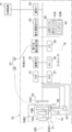
- the surveillance camera 10 includes a computer 19, a DSP 31, an image memory 32, an electronic shake correction unit 33, a communication I / F 34, a runout detection sensor 40, and a UI device 43.
- the computer 19 includes a memory 35, a storage 36, and a CPU 37.
- the electronic runout correction unit 33 is an example of an "electronic runout correction unit” according to the technique of the present disclosure.
- the CPU 37 is an example of the "imaging support device" according to the technique of the present disclosure.
- the image sensor 25, DSP 31, image memory 32, electronic runout correction unit 33, communication I / F 34, memory 35, storage 36, CPU 37, runout detection sensor 40, and UI device 43 are connected to the bus 38. ..
- the driver 23 is also connected to the bus 38.
- one bus is shown as the bus 38 for convenience of illustration, but a plurality of buses may be used.
- the bus 38 may be a serial bus or a parallel bus including a data bus, an address bus, a control bus, and the like.
- the memory 35 temporarily stores various information and is used as a work memory.
- An example of the memory 35 is RAM, but the memory 35 is not limited to this, and other types of storage devices may be used.
- the storage 36 is a non-volatile storage device.
- a flash memory is adopted as an example of the storage 36.
- the flash memory is merely an example, and examples of the storage 36 include various non-volatile memories such as a magnetoresistive memory and / or a ferroelectric memory in place of the flash memory or in combination with the flash memory. ..
- the non-volatile storage device may be EEPROM, HDD, and / or SSD or the like.
- Various programs for the surveillance camera 10 are stored in the storage 36.
- the CPU 37 reads various programs from the storage 36 and executes the read various programs on the memory 35 to control the entire surveillance camera 10.
- the image sensor 25 is a CMOS image sensor.
- the image sensor 25 images the monitored object at a predetermined frame rate under the instruction of the CPU 37.
- the "default frame rate" here refers to, for example, tens of frames / second to hundreds of frames / second.
- the image sensor 25 itself may also have a built-in control device (image sensor control device). In that case, the image sensor control device controls the inside of the image sensor 25 in detail according to the image pickup instruction output by the CPU 37. Do. Further, the image sensor 25 may image the target subject at a predetermined frame rate under the instruction of the DSP 31, and in this case, the detailed control inside the image sensor 25 is imaged according to the image pickup instruction output by the DSP 31. It is performed by the element control device.
- the DSP 31 is sometimes called an ISP.
- the light receiving surface 25A is formed by a plurality of photosensitive pixels (not shown) arranged in a matrix.
- each photosensitive pixel is exposed, and photoelectric conversion is performed for each photosensitive pixel.
- the electric charge obtained by performing photoelectric conversion for each photosensitive pixel is an analog imaging signal indicating a monitoring target.
- a plurality of photosensitive pixels a plurality of photoelectric conversion elements having sensitivity to visible light (for example, a photoelectric conversion element in which a color filter is arranged) are adopted.
- the plurality of photoelectric conversion elements include a photoelectric conversion element having sensitivity to R (red) light (for example, a photoelectric conversion element in which an R filter corresponding to R is arranged) and G (green) light.
- a photoelectric conversion element having sensitivity to for example, a photoelectric conversion element in which a G filter corresponding to G is arranged
- a photoelectric conversion element having sensitivity to B (blue) light for example, a B filter corresponding to B are arranged.
- the photoelectric conversion element has been adopted.
- the surveillance camera 10 performs imaging based on visible light (for example, light on the short wavelength side of about 700 nanometers or less).
- imaging may be performed based on infrared light (for example, light having a wavelength longer than about 700 nanometers).
- a plurality of photoelectric conversion elements having sensitivity to infrared light may be used as the plurality of photosensitive pixels.
- an InGaAs sensor and / or a type 2 quantum well (T2SL; Simulation of Type-II Quantum Well) sensor or the like may be used.
- the image pickup device 25 performs signal processing such as A / D conversion on the analog image pickup signal to generate a digital image which is a digital image pickup signal.
- the image sensor 25 is connected to the DSP 31 via the bus 38, and outputs the generated digital image to the DSP 31 in frame units via the bus 38.
- the digital image is an example of the "captured image" according to the technique of the present disclosure.
- the CMOS image sensor is described as an example of the image sensor 25 here, the technique of the present disclosure is not limited to this, and a CCD image sensor may be applied as the image sensor 25.
- the image sensor 25 is connected to the bus 38 via an AFE (not shown) built in the CCD driver, and the AFE performs signal processing such as A / D conversion on the analog image sensor obtained by the image sensor 25. Is applied to generate a digital image, and the generated digital image is output to the DSP 31.
- the CCD image sensor is driven by the CCD driver built into the AFE.
- the CCD driver may be provided independently.
- DSP31 performs various digital signal processing on digital images.
- the various digital signal processes refer to, for example, demosaic processing, noise removal processing, gradation correction processing, color correction processing, and the like.
- the DSP 31 outputs a digital image after digital signal processing to the image memory 32 for each frame.
- the image memory 32 stores a digital image from the DSP 31.
- the digital image stored in the image memory 32 is also referred to as an “captured image”.
- the runout detection sensor 40 is, for example, a device including a gyro sensor, and detects the runout of the surveillance camera 10. In other words, the runout detection sensor 40 detects the runout amount in each of the pair of axial directions.
- the gyro sensor detects the amount of rotational runout around each axis (see FIG. 1) of the pitch axis PA, the yaw axis YA, and the roll axis RA (the axis parallel to the optical axis OA).
- the runout detection sensor 40 measures the amount of rotational runout around the pitch axis PA and the amount of rotational runout around the yaw axis YA detected by the gyro sensor in a two-dimensional plane parallel to the pitch axis PA and the yaw axis YA.
- the amount of runout of the surveillance camera 10 is detected by converting it into the amount of runout of.
- the gyro sensor is mentioned as an example of the runout detection sensor 40, but this is just an example, and the runout detection sensor 40 may be an acceleration sensor.
- the accelerometer detects the amount of runout in a two-dimensional plane parallel to the pitch axis PA and the yaw axis YA.
- the runout detection sensor 40 outputs the detected runout amount to the CPU 37.
- the runout amount detection sensor 40 a form example in which the runout amount is detected by a physical sensor called the runout amount detection sensor 40 is given, but the technique of the present disclosure is not limited to this.
- the motion vector obtained by comparing the captured images stored in the image memory 32 in time series before and after may be used as the amount of runout.
- the amount of runout detected by the physical sensor and the amount of runout finally used may be derived based on the motion vector obtained by the image processing.
- the CPU 37 acquires the amount of runout detected by the runout amount detection sensor 40, and controls the mechanical runout correction unit 29 and the electronic runout correction unit 33 based on the acquired runout amount.
- the amount of runout detected by the runout amount detection sensor 40 is used for runout correction by each of the mechanical runout correction unit 29 and the electronic runout correction unit 33.
- the mechanical runout correction unit 29 and the electronic runout correction unit 33 correct the runout according to the runout amount detected by the runout amount detection sensor 40.
- the electronic runout correction unit 33 is a device including an ASIC.
- the electronic runout correction unit 33 corrects runout by performing image processing on the captured image in the image memory 32 based on the runout amount detected by the runout amount detection sensor 40.
- the electronic runout correction unit 33 may be a device including a plurality of ASICs, FPGAs, and PLDs.
- the electronic runout correction unit 33 a computer including a CPU, a storage, and a memory may be adopted. The number of CPUs may be singular or plural.
- the electronic runout correction unit 33 may be realized by a combination of a hardware configuration and a software configuration.
- the communication I / F 34 is, for example, a network interface, and controls transmission of various information to and from the management device 11 via the network.
- An example of a network is a WAN such as the Internet or a public communication network. It controls communication between the surveillance camera 10 and the management device 11.
- the UI device 43 includes a reception device 43A and a display 43B.
- the reception device 43A is, for example, a hard key, a touch panel, or the like, and receives various instructions from a user or the like of the monitoring system 2 (hereinafter, also simply referred to as “user or the like”).
- the CPU 37 acquires various instructions received by the reception device 43A and operates according to the acquired instructions.
- the display 43B displays various information under the control of the CPU 37. Examples of various information displayed on the display 43B include the contents of various instructions received by the reception device 43A, captured images, and the like.
- the swivel mechanism 16 includes a yaw shaft swivel mechanism 71, a pitch shaft swivel mechanism 72, a motor 73, a motor 74, a driver 75, and a driver 76.
- the yaw axis swivel mechanism 71 swivels the surveillance camera 10 in the yaw direction.
- the motor 73 generates power by driving under the control of the driver 75.
- the yaw axis swivel mechanism 71 swivels the surveillance camera 10 in the yaw direction by receiving the power generated by the motor 73.
- the motor 74 generates power by driving under the control of the driver 76.
- the pitch axis swivel mechanism 72 swivels the surveillance camera 10 in the pitch direction by receiving the power generated by the motor 74.
- the management device 11 includes a display 13, a secondary storage device 14, a control device 60, a reception device 62, and communication I / F 66 to 68.
- the control device 60 includes a CPU 60A, a storage 60B, and a memory 60C.
- Each of the reception device 62, the display 13, the CPU 60A, the storage 60B, the memory 60C, and the communication I / F 66 to 68 is connected to the bus 70.
- one bus is shown as the bus 70 for convenience of illustration, but a plurality of buses may be used.
- the bus 70 may be a serial bus or a parallel bus including a data bus, an address bus, a control bus, and the like.
- the memory 60C temporarily stores various information and is used as a work memory.
- An example of the memory 60C is RAM, but the present invention is not limited to this, and other types of storage devices may be used.
- the storage 60B is a non-volatile storage device.
- a flash memory is adopted as an example of the storage 60B.
- the flash memory is merely an example, and examples of the storage 60B include various non-volatile memories such as a magnetoresistive memory and / or a ferroelectric memory in place of the flash memory or in combination with the flash memory. .. Further, the non-volatile storage device may be EEPROM, HDD, and / or SSD or the like.
- management device programs Various programs for the management device 11 (hereinafter, simply referred to as “management device programs”) are stored in the storage 60B.
- the CPU 60A reads the management device program from the storage 60B and executes the read management device program on the memory 60C to control the entire management device 11.
- Communication I / F66 is, for example, a network interface.
- the communication I / F 66 is communicably connected to the communication I / F 34 of the surveillance camera 10 via a network, and controls transmission of various information with the surveillance camera 10.
- the communication I / F 66 requests the surveillance camera 10 to transmit the captured image, and receives the captured image transmitted from the communication I / F 34 of the surveillance camera 10 in response to the request for transmitting the captured image.
- Communication I / F 67 and 68 are, for example, network interfaces.
- the communication I / F 67 is communicably connected to the driver 75 via the network.
- the CPU 60A controls the turning operation of the yaw axis turning mechanism 71 by controlling the motor 73 via the communication I / F 67 and the driver 75.
- the communication I / F 68 is communicably connected to the driver 76 via the network.
- the CPU 60A controls the turning operation of the pitch axis turning mechanism 72 by controlling the motor 74 via the communication I / F 68 and the driver 76.
- the reception device 62 is, for example, a keyboard, a mouse, a touch panel, or the like, and receives various instructions from the user or the like.
- the CPU 60A acquires various instructions received by the receiving device 62 and operates according to the acquired instructions.
- the display 13 displays various information under the control of the CPU 60A. Examples of the various information displayed on the display 13 include the contents of various instructions received by the reception device 62, the captured image received by the communication I / F 66, and the like.
- the secondary storage device 14 stores various information under the control of the CPU 60A. Examples of various information stored in the secondary storage device 14 include captured images received by the communication I / F 66.
- control device 60 controls the display 13 to display the captured image received by the communication I / F 66, and stores the captured image received by the communication I / F 66 in the secondary storage device 14. Control to make it.
- the captured image displayed on the display 13 is an example of "an image reflecting the adjustment result of the position of the target subject image” according to the technique of the present disclosure.
- the captured image stored in the secondary storage device 14 is an example of "image data" according to the technique of the present disclosure.
- the captured image is displayed on the display 13 and the captured image received by the communication I / F 66 is stored in the secondary storage device 14, but the technique of the present disclosure is described. Not limited to this. For example, either the display of the captured image on the display 13 or the storage of the captured image in the secondary storage device 14 may be performed.
- the surveillance camera 10 is provided with a function of tracking a target subject (hereinafter, also referred to as a "tracking function").
- a target subject hereinafter, also referred to as a "tracking function"
- the position in the captured image of the target subject image indicating the target subject (for example, a specific person) included in the imaging area is set as the default in the captured image in preparation for the movement of the target subject. It is preferable to adjust to the position. For example, if the position of the target subject image is aligned with the center position of the captured image, it is possible to respond to changes in the position of the target subject image in various directions.
- the storage 36 stores the position adjustment program 36A and adjusts the position.
- Program 36A is executed by CPU 37.
- the CPU 37 reads the position adjustment program 36A from the storage 36 and executes the read position adjustment program 36A on the memory 35 to support imaging by the surveillance camera 10 including the image sensor 25. Functions as. In this way, the CPU 37 functions as an image pickup support device, so that the position of the target subject image by the surveillance camera 10 is taken as the center position of the captured image (hereinafter, also referred to as “image center position”).
- image center position is an example of the "default position" and the "specific position" according to the technique of the present disclosure.
- the surveillance camera 10 is provided with a position adjusting unit 52 in order to support imaging in a state where the position of the target subject image is set to a specific position by the surveillance camera 10.
- the position adjusting unit 52 has a turning mechanism 16 and a runout correction unit 51, and adjusts the position of the target subject image in the captured image.
- the CPU 37 supports the imaging by the surveillance camera 10 by controlling the position adjusting unit 52.
- the position adjusting unit 52 is an example of the “position adjusting device” according to the technique of the present disclosure.
- the CPU 37 derives the amount of movement required to move the position of the target subject image to the image center position by the position adjusting unit 52 based on various information. Further, the CPU 37 outputs the derived movement amount. By controlling the position adjusting unit 52 based on the amount of movement, the position of the target subject image can be adjusted to the image center position, and the tracking of the target subject is supported.
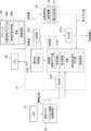
- the CPU 37 By executing the position adjustment program 36A on the memory 35, the CPU 37 operates as an acquisition unit 37A, a derivation unit 37B, a control unit 37C, an output unit 37D, and a determination unit 37E.
- the acquisition unit 37A is an example of the “acquisition unit” according to the technique of the present disclosure.
- the out-licensing unit 37B is an example of the “out-licensing unit” according to the technique of the present disclosure.
- the control unit 37C is an example of a “control unit” according to the technique of the present disclosure.
- the output unit 37D is an example of the “output unit” according to the technique of the present disclosure.
- the CPU 37 is an example of the "processor” according to the technique of the present disclosure
- the memory 35 is an example of the "memory" according to the technique of the present disclosure.
- the determination unit 37E acquires a captured image from the image memory 32, and performs image recognition on the target subject image with respect to the acquired captured image.
- the image recognition dictionary 36B is stored in the storage 36.
- a target subject image for example, an image showing a specific object
- the determination unit 37E determines whether or not the target subject image is included in the captured image by referring to the image recognition dictionary 36B of the storage 36. Further, when the target subject image is included in the captured image, the determination unit 37E determines whether or not the position of the target subject image is at the center position of the image.
- the acquisition unit 37A acquires the captured image from the image memory 32, refers to the acquired captured image, and refers to the image center position and the target subject.
- the amount of deviation from the position of the image (hereinafter, also referred to as "the amount of deviation in the image") is acquired.
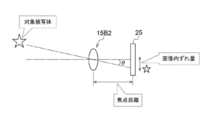
- the acquisition unit 37A calculates the amount of deviation of the pixel coordinates of the target subject image with respect to the image center position (see FIG. 7).
- the amount of deviation in pixel coordinates is an example of the amount of deviation in an image according to the technique of the present disclosure.
- the acquisition unit 37A acquires the focal length of the surveillance camera 10. Specifically, the acquisition unit 37A monitors the position of the zoom lens 15B2 on the optical axis OA, and derives the focal length based on the monitoring result. For the derivation of the focal length, for example, a focal length derivation table in which the monitoring result and the focal length are associated with each other, or a focal length derivation arithmetic expression in which the monitoring result is an independent variable and the focal length is a dependent variable is acquired. It is realized by being used by 37A.
- the storage 36 stores the sensitivity of the shake correction unit 51 (hereinafter, also simply referred to as “sensitivity”) and the pixel spacing of the pixels of the image sensor 25 (hereinafter, also simply referred to as “pixel spacing”).
- the acquisition unit 37A acquires the sensitivity from the storage 36.
- the sensitivity is the product of the amount of movement of the imaging region on the light receiving surface 25A per unit runout angle and the amount of movement of the shake correction unit 51 required to move the imaging region on the light receiving surface 25A once. Further, the acquisition unit 37A acquires the pixel interval from the storage 36.
- the derivation unit 37B derives the amount of movement required to move the position of the target subject image to the image center position by the position adjusting unit 52. Specifically, the derivation unit 37B derives the movement amount based on the in-image deviation amount acquired by the acquisition unit 37A, the focal length acquired by the acquisition unit 37A, and the pixel spacing.
- the pixel spacing is an example of "information about the pixel spacing" according to the technique of the present disclosure.
- the technique of the present disclosure is not limited to this, and the acquisition unit is not limited to this.
- the pixel interval may be derived from the size and the number of pixels of the captured image by 37A or the derivation unit 37B.
- the information regarding the size and the number of pixels of the captured image is an example of "information regarding the pixel spacing" according to the technique of the present disclosure.
- the acquisition unit 37A may acquire information on the pixel spacing from the image sensor 25.
- the out-licensing unit 37B may use the information on the pixel spacing acquired by the acquisition unit 37A as the information on the pixel spacing when deriving the movement amount.
- the control unit 37C operates the position adjustment unit 52 based on the movement amount derived by the out-licensing unit 37B to perform adjustment control for adjusting the position of the target subject image in the captured image.
- the control unit 37C adjusts the position of the target subject image in the captured image by operating the swivel mechanism 16 and the runout correction unit 51 included in the position adjustment unit 52 based on the movement amount derived by the out-licensing unit 37B. Perform adjustment control.
- control unit 37C has been described here with an example of a form in which both the swivel mechanism 16 and the runout correction unit 51 of the position adjustment unit 52 are operated, the technique of the present disclosure is not limited to this.
- control unit 37C may operate the swivel mechanism 16 or the runout correction unit 51 based on the movement amount derived by the out-licensing unit 37B.
- the control unit 37C performs time-division of the shake correction by the shake correction unit 51 and the adjustment control for adjusting the position of the target subject image in the captured image. Specifically, the control unit 37C causes the runout correction unit 51 to correct the runout while the surveillance camera 10 is swiveled by the swivel mechanism 16.
- the control unit 37C performs adjustment control while the rotation of the surveillance camera 10 by the rotation mechanism 16 (hereinafter, also referred to as “turning at the time of non-adjustment”) is stopped.
- the turning of the surveillance camera 10 by the turning mechanism 16 is roughly classified into a turning at the time of non-adjustment (turning at the normal time) and a turning at the time of adjustment (turning at a time other than the normal time).
- the turning at the time of adjustment refers to the turning at the time of adjusting the position of the target subject image by the turning mechanism 16 operated by performing the adjustment control.
- the time of adjustment refers to a timing different from that of the time of non-adjustment, and in other words, it means a timing in which the runout correction unit 51 has not corrected the runout.
- the control unit 37C adjusts the position of the target subject image by the turning mechanism 16 and then adjusts the position of the target subject image by the shake correction unit 51. Control the 51.
- the output unit 37D outputs the movement amount derived by the out-licensing unit 37B. Specifically, the output unit 37D outputs the movement amount derived by the out-licensing unit 37B to the management device 11.
- the management device 11 is an example of "external" according to the technique of the present disclosure.
- the movement amount is determined based on the first movement amount required for adjusting the position of the target subject image by the turning mechanism 16 and the second movement amount required for adjusting the position of the target subject image by the shake correction unit 51.
- the movement amount derived by the out-licensing unit 37B is determined by combining the first movement amount of the swivel mechanism 16 and the second movement amount of the runout correction unit 51.
- the first movement amount is determined based on the value obtained by dividing the product of the in-image deviation amount and the pixel spacing by the focal length.
- the out-licensing unit 37B derives the first movement amount by the following calculation formula (1).
- the pan-tilt angle ⁇ obtained by the following calculation formula (1) is an example of the “first movement amount” according to the technique of the present disclosure.
- ⁇ arctan (p ⁇ t / L) ⁇ ⁇ ⁇ ⁇ ⁇ ⁇ (1)
- ⁇ is the pan-tilt angle [deg]
- p is the amount of deviation of the pixel coordinates of the target subject image position [pixel]
- t is the pixel spacing [mm / pixel] of the image sensor.
- L is the focal length [mm].
- the out-licensing unit 37B derives the second movement amount.
- the second movement amount is derived by the out-licensing unit 37B as the movement amount required to move the run-out correction element of the run-out correction unit 51 from the current position to the center position.
- the movable range of the vibration isolator lens 15B1 which is the vibration correction element of the vibration correction unit 51, is defined due to structural restrictions of the surveillance camera 10. Therefore, as shown in FIG.
- the derivation unit 37B derives a second movement amount, which is a movement amount required to move the runout correction element to the center position of the movable range (hereinafter, also simply referred to as “the center position of the movable range”).
- the derivation unit 37B is a runout correction element required to move the runout correction element from the current position to the center position of the movable range based on the information on the amount of runout correction element deviation and the sensitivity of the runout correction unit 51 acquired by the acquisition unit 37A. Derivation of the amount of movement.
- the deviation amount of the runout correction element is the distance between the center position of the movable range and the current position of the runout correction element, and is acquired by the acquisition unit 37A based on the information output from the position detection sensor 39.
- the out-licensing unit 37B calculates the second movement amount by the following formula (2).
- the pan-tilt angle ⁇ obtained by the following formula is an example of the “second movement amount” according to the technique of the present disclosure.
- N the amount of deviation of the runout correction element [mm]
- k the sensitivity [mm / deg].
- the present embodiment has been described with reference to an example in which the vibration is corrected by moving the anti-vibration lens 15B1, the technique of the present disclosure is not limited to this.
- the image sensor 25 may be moved in a plane parallel to the two-dimensional plane of the anti-vibration lens to correct the vibration.
- the runout can be corrected within the movable range of the image sensor 25.
- the amount of deviation from the center position of the movable range of the image sensor 25 is acquired by the position detection sensor (not shown) of the image sensor 25.
- the image sensor 25 is an example of the “swing correction element” according to the technique of the present disclosure.
- the image sensor mobile runout correction mechanism (not shown), which is an example of the “shake correction component” according to the technique of the present disclosure, captures the power generated by a drive source such as a motor (for example, a voice coil motor).
- a drive source such as a motor (for example, a voice coil motor).
- the mechanical runout correction mechanism (not shown), which is an example of the "shake correction component” and the “optical runout correction mechanism” according to the technique of the present disclosure, is driven by a drive source such as a motor (for example, a voice coil motor).
- the vibration may be corrected by moving both the vibration isolation lens 15B1 and the image pickup element 25 using the generated power.
- the vibration can be corrected within the movable range of each of the vibration-proof lens 15B1 and the image sensor 25.
- the anti-vibration lens 15B1 and the image sensor 25 are examples of the "shake correction element" according to the technique of the present disclosure.
- the derivation unit 37B derives the movement amount by combining the first movement amount and the second movement amount.
- the movement amount derived by the out-licensing unit 37B is output by the output unit 37D.
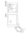
- the movement amount output by the output unit 37D is displayed on the display 13 of the management device 11. Specifically, the captured image is displayed on the display 13, and the pan-tilt angle as the movement amount is graphed and displayed on the movement amount display screen at a position adjacent to the captured image.
- the user or the like turns the surveillance camera 10 while referring to the movement amount displayed on the movement amount display screen.
- the case where the movement amount display screen is visually displayed is shown, but the audible display such as the output of the sound by the voice reproduction device (not shown) and the permanent visibility of the output of the printed matter by the printer and the like are shown.
- the display or the tactile display by the vibrator may be performed instead of the visible display, or may be used in combination with the visible display.
- the position of the target subject image deviates from the image center position.
- the current position of the runout correction element is also deviated from the center position of the movable range.
- the movement amount derived by the out-licensing unit 37B is displayed on the movement amount display screen.
- the user or the like swivels the surveillance camera 10 by swiveling the swivel mechanism 16 based on the displayed movement amount (see the middle part of FIG. 12).
- the position of the target subject image in the captured image is adjusted by operating the swivel mechanism 16.
- the position of the target subject image is adjusted by the shake correction unit 51 (see the lower part of FIG. 12).
- the resolution of adjusting the position of the target subject image by the shake correction unit 51 is higher than the resolution of adjusting the position of the target subject image by the turning mechanism 16. That is, the user or the like first makes a rough adjustment by the turning mechanism 16 and then makes a fine adjustment by the shake correction unit 51 for adjusting the position of the target subject image.
- the position of the target subject image moves to the image center position. That is, an image reflecting the adjustment result of the position of the target subject image is displayed as an captured image. Further, when the position of the target subject image is at the center position of the image, the shake correction element of the shake correction unit 51 is located at the center of the movable range.
- FIG. 13 shows an example of the flow of the position adjustment process executed by the CPU 37.
- the flow of the position adjustment process shown in FIG. 13 is an example of the "imaging support method" according to the technique of the present disclosure.
- step ST10 the determination unit 37E determines whether or not the target subject image is included in the captured image.
- step ST10 when the target subject image is included in the captured image, the determination is affirmed and the position adjustment process proceeds to step ST12.
- step ST10 if the captured image does not include the target subject image, the determination is denied and the position adjustment process proceeds to step ST32.
- step ST12 the determination unit 37E determines whether the position of the target subject image is at the image center position. When the position of the target subject image is at the center position of the image, the determination is affirmed, and the position adjustment process proceeds to step ST10. If the position of the target subject image is not at the image center position in step ST12, the determination is denied and the position adjustment process proceeds to step ST14.
- step ST14 the determination unit 37E determines whether the position adjustment by the turning mechanism 16 is necessary in order to move the position of the target subject image to the image center position. If the position adjustment by the turning mechanism 16 is not necessary in step ST14, the determination is denied and the position adjustment process shifts to step ST20. In step ST14, when the position adjustment by the turning mechanism 16 is necessary, the determination is affirmed, and the position adjustment process shifts to ST16.
- step ST16 the acquisition unit 37A acquires the amount of in-image deviation, the focal length, and the pixel spacing. After that, the position adjustment process proceeds to step ST18.
- step ST18 the derivation unit 37B derives the first movement amount based on the in-image shift amount and focal length acquired in step ST18, and the pixel spacing. After that, the position adjustment process shifts to step ST20.
- step ST20 the acquisition unit 37A determines whether the runout correction element is at the center position of the movable range. In step ST20, when the runout correction element is in the center position of the movable range, the determination is affirmed, and the position adjustment process shifts to step ST26. In step ST20, if the runout correction element is not at the center position of the movable range, the determination is denied, and then the position adjustment process shifts to step ST22.
- step ST22 the acquisition unit 37A acquires the amount of deviation of the runout correction element and the sensitivity. After that, the position adjustment process shifts to step ST24.
- step ST24 the out-licensing unit 37B derives the second movement amount based on the runout correction element deviation amount and the sensitivity. After that, the position adjustment process proceeds to step ST26.
- step ST26 the out-licensing unit 37B derives the movement amount based on the first movement amount and the second movement amount. After that, the position adjustment process shifts to step ST28.
- step ST28 the output unit 37D outputs the movement amount. After that, the position adjustment process shifts to step ST30.
- step ST30 the determination unit 37E determines whether the runout correction element is at the center position of the movable range. In step ST30, if the runout correction element is not at the center position of the movable range, the determination is denied, and then the position adjustment process shifts to step ST30. In step ST30, when the runout correction element is in the center position of the movable range, the determination is affirmed, and the position adjustment process shifts to step ST32.
- step ST32 the determination unit 37E determines whether or not the condition for ending the position adjustment process (hereinafter, referred to as "position adjustment process end condition") is satisfied.
- the position adjustment process end condition include a condition that the reception device 62 has received an instruction to end the position adjustment process. If the condition for ending the position adjustment process is not satisfied in step ST32, the determination is denied and the position adjustment process proceeds to step ST10. If the condition for ending the position adjustment process is satisfied in step ST32, the determination is affirmed and the position adjustment process ends.
- the surveillance camera 10 may track the target subject when capturing the imaging region including the target subject. In this case, it may be required to set the position of the target subject image in the captured image to a specific position in preparation for the movement of the target subject.
- the amount of movement required to move the position of the target subject image in the captured image to a specific position by the position adjusting unit 52 is based on the information on the amount of deviation in the image, the focal length, and the pixel spacing. Derived. Further, the surveillance camera 10 outputs the derived movement amount. Therefore, the surveillance camera 10 can support the tracking of the target subject when the imaging region including the target subject is imaged.
- a turning mechanism 16 and a runout correction unit 51 are used as the position adjusting unit 52. Therefore, as compared with the case where the position adjusting unit 52 is separately provided, the configuration is simplified by using the existing turning mechanism and the runout correction unit 51 as the position adjusting unit 52.
- the movement amount is determined based on the first movement amount required for the position adjustment of the target subject image by the turning mechanism 16 and the second movement amount required for the position adjustment of the target subject image by the shake correction unit 51. Be done. Therefore, as compared with the case where the movement amounts of the turning mechanism 16 and the runout correction unit 51 are the default values, the movement amounts suitable for the turning mechanism 16 and the runout correction unit 51 are set respectively.
- the shake correction unit 51 has a shake correction element which is at least one of the vibration isolation lens 15B1 and the image pickup element 25, and when the position of the target subject image is a specific position, the shake correction element is shake. It is located in the center of the movable range of the correction element. Therefore, when the position of the target subject image is adjusted to a specific position, a wider range in which the target subject image can be tracked can be secured as compared with the case where the shake correction element is located at a place other than the center.
- the sensitivity of the shake correction unit 51 is acquired, and the current position of the shake correction element is moved to the center position of the movable range as the second movement amount based on the deviation amount and the sensitivity of the shake correction element.
- the amount of movement required for is derived. Therefore, as compared with the case where the movement amount of the position of the target subject image by the shake correction unit 51 is an invariant value, it is determined based on the shake correction element deviation amount and the sensitivity, so that the movement amount of the target subject image can be accurately obtained.
- the first movement amount is determined by a value obtained by dividing the product of the amount of deviation in the image and the pixel spacing by the focal length. Therefore, as compared with the case where the movement amount of the position of the target subject image of the turning mechanism 16 is an invariant value, it is determined based on the in-image deviation amount, the pixel spacing, and the focal length, so that the movement amount of the target subject image can be accurately obtained. Be done.
- the movement amount is determined by combining the first movement amount and the second movement amount. Therefore, since the movement amount is derived as a value obtained by combining the first movement amount and the second movement amount, the display unit is compared with the case where the first movement amount and the second movement amount are derived separately. Subsequent processing such as display of is facilitated.
- runout correction and adjustment control by the runout correction unit 51 are performed in a time division manner. Therefore, as compared with the case where the runout correction and the adjustment control by the runout correction unit 51 are performed in parallel, the influence of one of the runout correction and adjustment control by the runout correction unit 51 on the other is suppressed. Can be done.
- the runout is corrected by the runout correction unit 51 while the turn by the turn mechanism 16 is performed, and the adjustment control is performed while the turn is stopped by the turn mechanism 16. Therefore, as compared with the case where the runout correction and the adjustment control are performed in parallel by the runout correction unit 51 while the surveillance camera 10 is turning and the turning of the surveillance camera 10 by the turning mechanism 16 is stopped. , Both the accuracy of the runout correction by the runout correction unit 51 and the accuracy of the adjustment control can be improved.
- the position of the target subject image is adjusted in a narrower range by the shake correction unit 51. Therefore, the accuracy of adjusting the position of the target subject image is improved as compared with the case where only the position of the target subject image is adjusted by the turning mechanism.
- the swivel mechanism 16 is a biaxial swivel mechanism
- the runout correction unit 51 is at least one of an optical runout correction mechanism and an electronic runout correction unit. Therefore, by combining the two-axis swivel mechanism with at least one of the optical shake correction mechanism and the electronic shake correction unit, the amount of movement required for adjusting the position of the target subject image in each direction of the two axes can be determined. Can be secured.
- the optical shake correction mechanism is at least one of a lens moving type shake correction mechanism and an image sensor moving type shake correction mechanism. Therefore, at least one of the lens movable shake correction mechanism and the image sensor movable shake correction mechanism can secure the amount of movement required for adjusting the position of the target subject image in each direction of the two axes.
- the surveillance camera 10 information regarding the pixel spacing of the pixels of the image sensor 25 is acquired by the acquisition unit 37A. Therefore, even if the information on the pixel spacing is updated, the amount of movement required to move the position of the target subject image to a specific position can be derived by using the latest information on the pixel spacing.
- the surveillance camera 10 outputs the derived movement amount to the outside. Therefore, it is possible to grasp the amount of movement required for the user or the like to move the position of the target subject image to a specific position.
- the movement amount output to the outside is displayed on the display 13 of the management device 11, but the technique of the present disclosure is not limited to this.
- the movement amount output from the output unit 37D may be displayed on the display 43B provided in the surveillance camera 10.
- the display 43B is an example of "external" according to the technique of the present disclosure.
- the movement amount derived by the out-licensing unit 37B is output from the output unit 37D.
- the output unit 37D outputs the movement amount to the display unit 53.
- Examples of the display unit 53 include a display 13 and / or a display 43B. This makes it possible for the operator or the like of the surveillance camera 10 to grasp the amount of movement required to move the position of the target subject image to the image center position.
- the case where the movement amount display screen is visually displayed is shown, but the audible display such as the output of the sound by the voice reproduction device (not shown) and the permanent visibility of the output of the printed matter by the printer and the like are shown.
- the display or the tactile display by the vibrator may be performed instead of the visible display, or may be used in combination with the visible display.
- the surveillance camera 10 and the swivel mechanism 16 may be communicably connected via the communication line 12.
- the surveillance camera 10 outputs the amount of movement required to move the position of the target subject image to the image center position from the control unit 37C to the turning mechanism 16.
- the swivel mechanism 16 swivels the surveillance camera 10 by the amount of movement input from the control unit 37C.
- the position of the target subject image in the captured image changes with the passage of time due to the movement of the target subject. That is, the amount of in-image shift between the image center position and the position of the target subject image changes. Therefore, the amount of movement required to move the position of the target subject image to the image center position must also be a movement amount that takes into consideration the movement of the target subject.
- the determination unit 37E determines whether the position of the target subject image has changed in the captured image.
- the acquisition unit 37A acquires the moving speed of the target subject image by calculating the amount of movement of the target subject image between frames of the captured image stored in the image memory 32 per unit time.
- the derivation unit 37B derives the amount of movement required to set the position of the target subject image to the image center position based on the movement speed.
- the determination unit 37E decomposes the moving speed of the target subject image into the vertical direction and the horizontal direction in the captured image to obtain a plurality of speeds.
- the vertical and horizontal directions in the captured image are examples of "plurality of different directions" according to the technique of the present disclosure.
- the determination unit 37E obtains the speed of the components in each direction. .. Further, the determination unit 37E compares the speeds of the horizontal component and the vertical component of the captured image. Further, the determination unit 37E determines whether or not the component in the direction of increasing speed is directed toward the image center position side. Then, the derivation unit 37B determines whether or not to output the derived movement amount based on the determination result of whether or not the component in the direction having the higher speed is in the direction toward the image center position side.
- the derivation unit 37B does not output the amount of movement of the captured image in the lateral direction (pan direction). Therefore, in the initial state, the movement amount of the captured image is displayed only in the vertical direction (tilt direction) on the movement amount display screen (see the upper part of FIG. 19).
- the position of the target subject image in the captured image changes in the direction approaching the image center position (see the lower part of FIG. 19).
- the derivation unit 37B outputs the amount of movement in the horizontal direction (pan direction) in addition to the vertical direction (tilt direction) of the captured image. Therefore, in the initial state, the movement amount (pan tilt angle) in the horizontal direction (pan direction) and the vertical direction (tilt direction) of the captured image is displayed on the movement amount display screen (see the upper part of FIG. 20). After the position adjustment by the position adjusting unit 52 is completed, the position of the target subject image in the captured image becomes a specific position (see the lower part of FIG. 20).
- FIGS. 21A and 21B show an example of the flow of the position adjustment process executed by the CPU 37.
- the flow of the position adjustment process shown in FIGS. 21A and 21B is an example of the "imaging support method" according to the technique of the present disclosure.
- step ST10 the determination unit 37E determines whether or not the target subject image is included in the captured image.
- step ST10 when the target subject image is included in the captured image, the determination is affirmed and the position adjustment process proceeds to step ST34.
- step ST10 if the captured image does not include the target subject image, the determination is denied and the position adjustment process proceeds to step ST32.
- step ST34 the determination unit 37E executes the speed determination process shown in FIG. 21B as an example.
- the determination unit 37E determines whether the position of the target subject image is moving in the captured image. If the position of the target subject image is moving in step ST40, the determination is affirmed, and the speed determination process shifts to step ST42. In the determination in step ST40, if the position of the target subject image has not moved, the determination is denied, and the speed determination process shifts to step ST14 of the position adjustment process shown in FIG. 21A.
- step ST42 the determination unit 37E is decomposed in two directions in which the moving speeds of the target subjects are different. After that, the speed determination process proceeds to step ST44.
- step ST44 the determination unit 37E compares the speeds of the components decomposed in step ST42 in each direction. After that, the speed determination process proceeds to step ST46.
- step ST46 the determination unit 37E determines whether or not the component having the higher speed among the directions compared in step ST44 is the direction toward the image center position. In step ST46, when the component having the higher speed is in the direction toward the image center position, the determination is affirmed, and the speed determination process proceeds to step ST48. In step ST46, if the component having the higher speed is not in the direction toward the image center position, the determination is denied, and the speed determination process shifts to step ST14 of the position adjustment process shown in FIG. 21A.
- step ST48 the out-licensing unit 37B controls the output unit 37D so that the movement amount of the component having the higher speed is not output. After that, the speed determination process proceeds to step ST12 of the position adjustment process shown in FIG. 21A.
- the surveillance camera 10 according to the second embodiment, it is possible to adjust the position in consideration of the moving speed of the moving target subject even while the target subject is moving.
- the position adjustment can be performed with high accuracy even while the target subject is moving, as compared with the case where the moving speed is the speed in only one direction. It can be realized.
- the movement amount obtained by combining the first movement amount and the second movement amount has been described with reference to a form example in which the movement amount is displayed on the display 13, but the technique of the present disclosure is not limited to this.
- the first movement amount and the second movement amount may be displayed by separate indicators.
- the specific position and the default position are described with reference to the image center position, but the technique of the present disclosure is not limited to this.
- the specific position and the default position may be set to an arbitrary position in the captured image (for example, one of the four corners in the captured image) by the user or the like.
- a device including an ASIC and an FPGA is illustrated, but the technique of the present disclosure is not limited to this, and various processes may be realized by a software configuration by a computer.
- the surveillance camera 10 has a built-in computer 19.
- the position adjustment program 36A for causing the computer 19 to execute the position adjustment process according to the above embodiment is stored in the storage medium 100 which is a non-temporary storage medium.
- An example of the storage medium 100 is any portable storage medium such as an SSD or a USB memory.
- the computer 19 includes a CPU 37, a storage 36, and a memory 35.
- the storage 36 is a non-volatile storage device such as EEPROM, and the memory 35 is a volatile storage device such as RAM.
- the position adjustment program 36A stored in the storage medium 100 is installed in the computer 19.
- the CPU 37 executes the position adjustment process according to the position adjustment program 36A.
- the position adjustment program 36A may be stored in the storage 36 instead of the storage medium 100.
- the CPU 37 reads the position adjustment program 36A from the storage 36 and executes the read position adjustment program 36A on the memory 35. In this way, the position adjustment process is realized by executing the position adjustment program 36A by the CPU 37.
- the position adjustment program 36A is stored in a storage unit of another computer or server device connected to the computer 19 via a communication network (not shown), and the position adjustment is performed in response to the above-mentioned request of the surveillance camera 10.
- Program 36A may be downloaded and installed on computer 19.
- the CPU 37 is a single CPU, but may be a plurality of CPUs. Further, the GPU may be applied instead of the CPU 37.
- a computer 19 is illustrated, but the technique of the present disclosure is not limited to this, and a device including an ASIC, FPGA, and / or PLD may be applied instead of the computer 19. .. Further, instead of the computer 19, a combination of a hardware configuration and a software configuration may be used.
- the processor includes software, that is, a CPU, which is a general-purpose processor that functions as a hardware resource for executing position adjustment processing by executing a program.
- examples of the processor include a dedicated electric circuit which is a processor having a circuit configuration specially designed for executing a specific process such as FPGA, PLD, or ASIC.
- a memory is built in or connected to each processor, and each processor executes a position adjustment process by using the memory.
- the hardware resource that performs the alignment process may consist of one of these various processors, or a combination of two or more processors of the same type or dissimilarity (eg, a combination of multiple FPGAs, or a combination of multiple FPGAs). It may be composed of a combination of a CPU and an FPGA). Further, the hardware resource for executing the position adjustment process may be one processor.
- one processor is configured by a combination of one or more CPUs and software, and this processor functions as a hardware resource for executing position adjustment processing. ..
- SoC there is a form in which a processor that realizes the functions of the entire system including a plurality of hardware resources for executing position adjustment processing with one IC chip is used.
- the position adjustment process is realized by using one or more of the above-mentioned various processors as a hardware resource.
- the surveillance camera 10 is illustrated, but the technique of the present disclosure is not limited to this. That is, the technique of the present disclosure is also applied to various electronic devices having a built-in imaging device (for example, interchangeable lens cameras, fixed lens cameras, smart devices, personal computers, and / or wearable terminal devices, etc.). It is possible, and even with these electronic devices, the same operations and effects as those of the above-mentioned surveillance camera 10 can be obtained.
- a built-in imaging device for example, interchangeable lens cameras, fixed lens cameras, smart devices, personal computers, and / or wearable terminal devices, etc.
- the display 43B is illustrated, but the technique of the present disclosure is not limited to this.
- a separate display connected to the image pickup apparatus may be used as a "display unit" according to the technique of the present disclosure.
- a and / or B is synonymous with "at least one of A and B". That is, “A and / or B” means that it may be only A, only B, or a combination of A and B. Further, in the present specification, when three or more matters are connected and expressed by "and / or", the same concept as “A and / or B" is applied.
- the processor Includes memory built into or connected to the processor The above processor The amount of in-image deviation between the predetermined position in the captured image obtained by capturing the imaging region including the target subject by the image sensor and the position of the target subject image indicating the target subject, and the focal length of the imaging device. To get and The amount of movement required to move the position of the target subject image to a specific position by the position adjusting unit that adjusts the position of the target subject image in the captured image is the amount of deviation in the image acquired by the acquisition unit. , Derived based on the information on the focal length acquired by the acquisition unit and the pixel spacing of the pixels in the image sensor. An information processing device that outputs the movement amount derived by the derivation unit.
Landscapes
- Engineering & Computer Science (AREA)
- Multimedia (AREA)
- Signal Processing (AREA)
- General Engineering & Computer Science (AREA)
- Physics & Mathematics (AREA)
- General Physics & Mathematics (AREA)
- Mechanical Engineering (AREA)
- Studio Devices (AREA)
- Adjustment Of Camera Lenses (AREA)
- Accessories Of Cameras (AREA)
Priority Applications (6)
| Application Number | Priority Date | Filing Date | Title |
|---|---|---|---|
| JP2021553467A JP7222113B2 (ja) | 2019-10-29 | 2020-10-20 | 撮像支援装置、撮像装置、撮像システム、撮像支援システム、撮像支援方法、及びプログラム |
| CN202080075962.7A CN114616820B (zh) | 2019-10-29 | 2020-10-20 | 摄像支援装置、摄像装置、摄像系统、摄像支援系统、摄像支援方法及存储介质 |
| US17/728,991 US11711612B2 (en) | 2019-10-29 | 2022-04-26 | Imaging support device, imaging apparatus, imaging system, imaging support system, imaging support method, and program |
| JP2023012143A JP7612725B2 (ja) | 2019-10-29 | 2023-01-30 | 撮像支援装置、撮像装置、撮像システム、撮像支援システム、撮像支援方法、及びプログラム |
| US18/327,214 US11968448B2 (en) | 2019-10-29 | 2023-06-01 | Imaging support device, imaging apparatus, imaging system, imaging support system, imaging support method, and program |
| US18/435,071 US12155931B2 (en) | 2019-10-29 | 2024-02-07 | Imaging support device, imaging apparatus, imaging system, imaging support system, imaging support method, and program |
Applications Claiming Priority (2)
| Application Number | Priority Date | Filing Date | Title |
|---|---|---|---|
| JP2019196681 | 2019-10-29 | ||
| JP2019-196681 | 2019-10-29 |
Related Child Applications (1)
| Application Number | Title | Priority Date | Filing Date |
|---|---|---|---|
| US17/728,991 Continuation US11711612B2 (en) | 2019-10-29 | 2022-04-26 | Imaging support device, imaging apparatus, imaging system, imaging support system, imaging support method, and program |
Publications (1)
| Publication Number | Publication Date |
|---|---|
| WO2021085247A1 true WO2021085247A1 (ja) | 2021-05-06 |
Family
ID=75715103
Family Applications (1)
| Application Number | Title | Priority Date | Filing Date |
|---|---|---|---|
| PCT/JP2020/039425 Ceased WO2021085247A1 (ja) | 2019-10-29 | 2020-10-20 | 撮像支援装置、撮像装置、撮像システム、撮像支援システム、撮像支援方法、及びプログラム |
Country Status (4)
| Country | Link |
|---|---|
| US (3) | US11711612B2 (https=) |
| JP (2) | JP7222113B2 (https=) |
| CN (1) | CN114616820B (https=) |
| WO (1) | WO2021085247A1 (https=) |
Cited By (1)
| Publication number | Priority date | Publication date | Assignee | Title |
|---|---|---|---|---|
| FR3136925A1 (fr) * | 2022-06-16 | 2023-12-22 | SNCF Voyageurs | Système et procédé de calibration d’une caméra de vidéosurveillance dans un véhicule ferroviaire |
Families Citing this family (2)
| Publication number | Priority date | Publication date | Assignee | Title |
|---|---|---|---|---|
| JP2024122689A (ja) * | 2023-02-28 | 2024-09-09 | ラピステクノロジー株式会社 | 撮影システム |
| CN116095489B (zh) * | 2023-04-11 | 2023-06-09 | 北京城建智控科技股份有限公司 | 一种基于摄像装置的协同防抖方法与存储介质 |
Citations (2)
| Publication number | Priority date | Publication date | Assignee | Title |
|---|---|---|---|---|
| JP2013005009A (ja) * | 2011-06-13 | 2013-01-07 | Pentax Ricoh Imaging Co Ltd | 天体自動追尾撮影方法及び天体自動追尾撮影装置 |
| JP2018042098A (ja) * | 2016-09-07 | 2018-03-15 | キヤノン株式会社 | ブレ補正装置およびその制御方法、撮像装置 |
Family Cites Families (41)
| Publication number | Priority date | Publication date | Assignee | Title |
|---|---|---|---|---|
| JP3380402B2 (ja) * | 1996-08-07 | 2003-02-24 | シャープ株式会社 | 撮像装置 |
| JP4010254B2 (ja) * | 2003-02-06 | 2007-11-21 | ソニー株式会社 | 画像記録再生装置、画像撮影装置及び色収差補正方法 |
| US7557832B2 (en) * | 2005-08-12 | 2009-07-07 | Volker Lindenstruth | Method and apparatus for electronically stabilizing digital images |
| JP2007267004A (ja) * | 2006-03-28 | 2007-10-11 | Canon Inc | 撮像装置 |
| JP2008124850A (ja) * | 2006-11-14 | 2008-05-29 | Matsushita Electric Ind Co Ltd | 画像動き補正装置、レンズ装置および撮像装置 |
| JP5284169B2 (ja) * | 2009-04-07 | 2013-09-11 | キヤノン株式会社 | 像振れ補正装置およびそれを具備する光学機器、撮像装置 |
| JP5361551B2 (ja) * | 2009-06-10 | 2013-12-04 | キヤノン株式会社 | 像振れ補正装置およびそれを備える光学機器、撮像装置、並びに像振れ補正装置の制御方法 |
| JP4857363B2 (ja) * | 2009-06-11 | 2012-01-18 | キヤノン株式会社 | 像振れ補正装置および撮像装置 |
| JP5121911B2 (ja) * | 2010-10-19 | 2013-01-16 | キヤノン株式会社 | 防振制御装置、撮像装置、及び防振制御方法 |
| WO2012141193A1 (ja) * | 2011-04-12 | 2012-10-18 | 富士フイルム株式会社 | 撮像装置 |
| JP5913960B2 (ja) * | 2011-12-21 | 2016-05-11 | キヤノン株式会社 | 防振制御装置及びその制御方法、及び撮像装置 |
| EP2806308B1 (en) * | 2012-01-19 | 2016-09-07 | Olympus Corporation | Shaking amount detecting apparatus, image pickup apparatus, and shaking amount detecting method |
| JP6097522B2 (ja) * | 2012-10-22 | 2017-03-15 | キヤノン株式会社 | 像ブレ補正装置及び像ブレ補正方法、撮像装置 |
| JP6494202B2 (ja) * | 2013-08-07 | 2019-04-03 | キヤノン株式会社 | 像振れ補正装置、その制御方法、および撮像装置 |
| JP2015034879A (ja) * | 2013-08-08 | 2015-02-19 | キヤノン株式会社 | 像振れ補正装置およびその制御方法、レンズ鏡筒、光学機器、並びに撮像装置 |
| JP6170395B2 (ja) * | 2013-09-26 | 2017-07-26 | キヤノン株式会社 | 撮像装置およびその制御方法 |
| JP6210824B2 (ja) * | 2013-10-02 | 2017-10-11 | オリンパス株式会社 | 焦点調節装置および焦点調節方法 |
| US10311595B2 (en) * | 2013-11-19 | 2019-06-04 | Canon Kabushiki Kaisha | Image processing device and its control method, imaging apparatus, and storage medium |
| JP6056774B2 (ja) * | 2014-01-17 | 2017-01-11 | ソニー株式会社 | 撮像装置と撮像方法およびプログラム。 |
| JP6472176B2 (ja) * | 2014-06-10 | 2019-02-20 | キヤノン株式会社 | 撮像装置、像振れ補正装置、撮像装置の制御方法及び像振れ補正方法 |
| JP6486656B2 (ja) * | 2014-11-11 | 2019-03-20 | オリンパス株式会社 | 撮像装置 |
| JP6381433B2 (ja) * | 2014-12-15 | 2018-08-29 | オリンパス株式会社 | カメラシステム及びそのブレ補正方法 |
| JP6584259B2 (ja) * | 2015-09-25 | 2019-10-02 | キヤノン株式会社 | 像ブレ補正装置、撮像装置および制御方法 |
| CN108141533B (zh) * | 2015-09-30 | 2020-07-21 | 富士胶片株式会社 | 摄像系统、视角调整方法及非暂时有形存储介质 |
| JP6833461B2 (ja) * | 2015-12-08 | 2021-02-24 | キヤノン株式会社 | 制御装置および制御方法、撮像装置 |
| US10270973B2 (en) | 2015-12-08 | 2019-04-23 | Canon Kabushiki Kaisha | Control device and imaging apparatus with a subject selectable mode with higher image blur correction |
| JP6613149B2 (ja) | 2016-01-15 | 2019-11-27 | キヤノン株式会社 | 像ブレ補正装置及びその制御方法、撮像装置、プログラム、記憶媒体 |
| US10142546B2 (en) * | 2016-03-16 | 2018-11-27 | Ricoh Imaging Company, Ltd. | Shake-correction device and shake-correction method for photographing apparatus |
| US10038849B2 (en) * | 2016-03-16 | 2018-07-31 | Panasonic Intellectual Property Mangement Co., Ltd. | Imaging device with controlled timing of images to be synthesized based on shake residual |
| US10247954B2 (en) * | 2016-03-29 | 2019-04-02 | Ricoh Imaging Company, Ltd. | Stage apparatus having shake-correction function |
| CN106257911A (zh) * | 2016-05-20 | 2016-12-28 | 上海九鹰电子科技有限公司 | 用于视频图像的图像稳定方法和装置 |
| JP6742819B2 (ja) | 2016-05-30 | 2020-08-19 | キヤノン株式会社 | 像ブレ補正装置、光学機器、撮像装置および制御方法 |
| KR102612988B1 (ko) * | 2016-10-20 | 2023-12-12 | 삼성전자주식회사 | 디스플레이 장치 및 디스플레이 장치의 영상 처리 방법 |
| JP6940290B2 (ja) * | 2017-03-31 | 2021-09-22 | パナソニックi−PROセンシングソリューションズ株式会社 | カメラ装置及び揺れ補正方法 |
| JP6936034B2 (ja) * | 2017-03-31 | 2021-09-15 | パナソニックi−PROセンシングソリューションズ株式会社 | カメラ装置及び揺れ補正方法 |
| JP6933487B2 (ja) | 2017-04-05 | 2021-09-08 | ローム株式会社 | アクチュエータドライバ、およびこれを用いた撮像装置、ならびに撮像方法 |
| JP6960238B2 (ja) * | 2017-04-28 | 2021-11-05 | キヤノン株式会社 | 像ブレ補正装置及びその制御方法、プログラム、記憶媒体 |
| US10462370B2 (en) * | 2017-10-03 | 2019-10-29 | Google Llc | Video stabilization |
| JP2019106656A (ja) * | 2017-12-14 | 2019-06-27 | ルネサスエレクトロニクス株式会社 | 半導体装置および電子機器 |
| US10764495B2 (en) * | 2017-12-14 | 2020-09-01 | Ricoh Company, Ltd. | Image processing apparatus, image processing method, storage medium, system, and electronic apparatus |
| JP2019145958A (ja) * | 2018-02-19 | 2019-08-29 | キヤノン株式会社 | 撮像装置およびその制御方法ならびにプログラム |
-
2020
- 2020-10-20 CN CN202080075962.7A patent/CN114616820B/zh active Active
- 2020-10-20 JP JP2021553467A patent/JP7222113B2/ja active Active
- 2020-10-20 WO PCT/JP2020/039425 patent/WO2021085247A1/ja not_active Ceased
-
2022
- 2022-04-26 US US17/728,991 patent/US11711612B2/en active Active
-
2023
- 2023-01-30 JP JP2023012143A patent/JP7612725B2/ja active Active
- 2023-06-01 US US18/327,214 patent/US11968448B2/en active Active
-
2024
- 2024-02-07 US US18/435,071 patent/US12155931B2/en active Active
Patent Citations (2)
| Publication number | Priority date | Publication date | Assignee | Title |
|---|---|---|---|---|
| JP2013005009A (ja) * | 2011-06-13 | 2013-01-07 | Pentax Ricoh Imaging Co Ltd | 天体自動追尾撮影方法及び天体自動追尾撮影装置 |
| JP2018042098A (ja) * | 2016-09-07 | 2018-03-15 | キヤノン株式会社 | ブレ補正装置およびその制御方法、撮像装置 |
Cited By (1)
| Publication number | Priority date | Publication date | Assignee | Title |
|---|---|---|---|---|
| FR3136925A1 (fr) * | 2022-06-16 | 2023-12-22 | SNCF Voyageurs | Système et procédé de calibration d’une caméra de vidéosurveillance dans un véhicule ferroviaire |
Also Published As
| Publication number | Publication date |
|---|---|
| US20230308757A1 (en) | 2023-09-28 |
| JP2023052772A (ja) | 2023-04-12 |
| US11711612B2 (en) | 2023-07-25 |
| JP7222113B2 (ja) | 2023-02-14 |
| CN114616820B (zh) | 2024-06-11 |
| JPWO2021085247A1 (https=) | 2021-05-06 |
| CN114616820A (zh) | 2022-06-10 |
| US20240187733A1 (en) | 2024-06-06 |
| US12155931B2 (en) | 2024-11-26 |
| JP7612725B2 (ja) | 2025-01-14 |
| US20220256083A1 (en) | 2022-08-11 |
| US11968448B2 (en) | 2024-04-23 |
Similar Documents
| Publication | Publication Date | Title |
|---|---|---|
| JP7612725B2 (ja) | 撮像支援装置、撮像装置、撮像システム、撮像支援システム、撮像支援方法、及びプログラム | |
| JP7499894B2 (ja) | 撮像支援装置、撮像支援システム、撮像システム、撮像支援方法、及びプログラム | |
| JP7456043B2 (ja) | 撮像支援装置、撮像支援システム、撮像システム、撮像支援方法、及びプログラム | |
| JP5926462B2 (ja) | 光学防震カメラモジュールの自動調節方法及びシステム | |
| WO2018168406A1 (ja) | 撮影制御装置、撮影システム、および撮影制御方法 | |
| US12101555B2 (en) | Imaging support device, imaging apparatus, imaging system, imaging support method, and program | |
| JP7209107B2 (ja) | 撮像支援装置、撮像装置、撮像システム、撮像支援システム、撮像支援方法、及びプログラム | |
| CN101640811A (zh) | 照相机 | |
| CN108038888A (zh) | 混合相机系统及其空间标定方法及装置 | |
| JP2012165426A5 (https=) |
Legal Events
| Date | Code | Title | Description |
|---|---|---|---|
| 121 | Ep: the epo has been informed by wipo that ep was designated in this application |
Ref document number: 20882368 Country of ref document: EP Kind code of ref document: A1 |
|
| ENP | Entry into the national phase |
Ref document number: 2021553467 Country of ref document: JP Kind code of ref document: A |
|
| NENP | Non-entry into the national phase |
Ref country code: DE |
|
| 122 | Ep: pct application non-entry in european phase |
Ref document number: 20882368 Country of ref document: EP Kind code of ref document: A1 |