WO2021085247A1 - Image capturing assistance device, image capturing device, image capturing system, image capturing assistance system, image capturing assistance method, and program - Google Patents
Image capturing assistance device, image capturing device, image capturing system, image capturing assistance system, image capturing assistance method, and program Download PDFInfo
- Publication number
- WO2021085247A1 WO2021085247A1 PCT/JP2020/039425 JP2020039425W WO2021085247A1 WO 2021085247 A1 WO2021085247 A1 WO 2021085247A1 JP 2020039425 W JP2020039425 W JP 2020039425W WO 2021085247 A1 WO2021085247 A1 WO 2021085247A1
- Authority
- WO
- WIPO (PCT)
- Prior art keywords
- image
- target subject
- amount
- imaging
- runout
- Prior art date
Links
Images


Classifications
-
- F—MECHANICAL ENGINEERING; LIGHTING; HEATING; WEAPONS; BLASTING
- F16—ENGINEERING ELEMENTS AND UNITS; GENERAL MEASURES FOR PRODUCING AND MAINTAINING EFFECTIVE FUNCTIONING OF MACHINES OR INSTALLATIONS; THERMAL INSULATION IN GENERAL
- F16M—FRAMES, CASINGS OR BEDS OF ENGINES, MACHINES OR APPARATUS, NOT SPECIFIC TO ENGINES, MACHINES OR APPARATUS PROVIDED FOR ELSEWHERE; STANDS; SUPPORTS
- F16M11/00—Stands or trestles as supports for apparatus or articles placed thereon Stands for scientific apparatus such as gravitational force meters
- F16M11/02—Heads
- F16M11/04—Means for attachment of apparatus; Means allowing adjustment of the apparatus relatively to the stand
- F16M11/06—Means for attachment of apparatus; Means allowing adjustment of the apparatus relatively to the stand allowing pivoting
- F16M11/10—Means for attachment of apparatus; Means allowing adjustment of the apparatus relatively to the stand allowing pivoting around a horizontal axis
-
- H—ELECTRICITY
- H04—ELECTRIC COMMUNICATION TECHNIQUE
- H04N—PICTORIAL COMMUNICATION, e.g. TELEVISION
- H04N23/00—Cameras or camera modules comprising electronic image sensors; Control thereof
- H04N23/60—Control of cameras or camera modules
- H04N23/67—Focus control based on electronic image sensor signals
-
- F—MECHANICAL ENGINEERING; LIGHTING; HEATING; WEAPONS; BLASTING
- F16—ENGINEERING ELEMENTS AND UNITS; GENERAL MEASURES FOR PRODUCING AND MAINTAINING EFFECTIVE FUNCTIONING OF MACHINES OR INSTALLATIONS; THERMAL INSULATION IN GENERAL
- F16M—FRAMES, CASINGS OR BEDS OF ENGINES, MACHINES OR APPARATUS, NOT SPECIFIC TO ENGINES, MACHINES OR APPARATUS PROVIDED FOR ELSEWHERE; STANDS; SUPPORTS
- F16M11/00—Stands or trestles as supports for apparatus or articles placed thereon Stands for scientific apparatus such as gravitational force meters
- F16M11/02—Heads
- F16M11/18—Heads with mechanism for moving the apparatus relatively to the stand
-
- F—MECHANICAL ENGINEERING; LIGHTING; HEATING; WEAPONS; BLASTING
- F16—ENGINEERING ELEMENTS AND UNITS; GENERAL MEASURES FOR PRODUCING AND MAINTAINING EFFECTIVE FUNCTIONING OF MACHINES OR INSTALLATIONS; THERMAL INSULATION IN GENERAL
- F16M—FRAMES, CASINGS OR BEDS OF ENGINES, MACHINES OR APPARATUS, NOT SPECIFIC TO ENGINES, MACHINES OR APPARATUS PROVIDED FOR ELSEWHERE; STANDS; SUPPORTS
- F16M11/00—Stands or trestles as supports for apparatus or articles placed thereon Stands for scientific apparatus such as gravitational force meters
- F16M11/20—Undercarriages with or without wheels
- F16M11/2007—Undercarriages with or without wheels comprising means allowing pivoting adjustment
- F16M11/2014—Undercarriages with or without wheels comprising means allowing pivoting adjustment around a vertical axis
-
- F—MECHANICAL ENGINEERING; LIGHTING; HEATING; WEAPONS; BLASTING
- F16—ENGINEERING ELEMENTS AND UNITS; GENERAL MEASURES FOR PRODUCING AND MAINTAINING EFFECTIVE FUNCTIONING OF MACHINES OR INSTALLATIONS; THERMAL INSULATION IN GENERAL
- F16M—FRAMES, CASINGS OR BEDS OF ENGINES, MACHINES OR APPARATUS, NOT SPECIFIC TO ENGINES, MACHINES OR APPARATUS PROVIDED FOR ELSEWHERE; STANDS; SUPPORTS
- F16M13/00—Other supports for positioning apparatus or articles; Means for steadying hand-held apparatus or articles
- F16M13/02—Other supports for positioning apparatus or articles; Means for steadying hand-held apparatus or articles for supporting on, or attaching to, an object, e.g. tree, gate, window-frame, cycle
-
- G—PHYSICS
- G03—PHOTOGRAPHY; CINEMATOGRAPHY; ANALOGOUS TECHNIQUES USING WAVES OTHER THAN OPTICAL WAVES; ELECTROGRAPHY; HOLOGRAPHY
- G03B—APPARATUS OR ARRANGEMENTS FOR TAKING PHOTOGRAPHS OR FOR PROJECTING OR VIEWING THEM; APPARATUS OR ARRANGEMENTS EMPLOYING ANALOGOUS TECHNIQUES USING WAVES OTHER THAN OPTICAL WAVES; ACCESSORIES THEREFOR
- G03B15/00—Special procedures for taking photographs; Apparatus therefor
-
- G—PHYSICS
- G03—PHOTOGRAPHY; CINEMATOGRAPHY; ANALOGOUS TECHNIQUES USING WAVES OTHER THAN OPTICAL WAVES; ELECTROGRAPHY; HOLOGRAPHY
- G03B—APPARATUS OR ARRANGEMENTS FOR TAKING PHOTOGRAPHS OR FOR PROJECTING OR VIEWING THEM; APPARATUS OR ARRANGEMENTS EMPLOYING ANALOGOUS TECHNIQUES USING WAVES OTHER THAN OPTICAL WAVES; ACCESSORIES THEREFOR
- G03B17/00—Details of cameras or camera bodies; Accessories therefor
- G03B17/56—Accessories
- G03B17/561—Support related camera accessories
-
- G—PHYSICS
- G03—PHOTOGRAPHY; CINEMATOGRAPHY; ANALOGOUS TECHNIQUES USING WAVES OTHER THAN OPTICAL WAVES; ELECTROGRAPHY; HOLOGRAPHY
- G03B—APPARATUS OR ARRANGEMENTS FOR TAKING PHOTOGRAPHS OR FOR PROJECTING OR VIEWING THEM; APPARATUS OR ARRANGEMENTS EMPLOYING ANALOGOUS TECHNIQUES USING WAVES OTHER THAN OPTICAL WAVES; ACCESSORIES THEREFOR
- G03B5/00—Adjustment of optical system relative to image or object surface other than for focusing
-
- H—ELECTRICITY
- H04—ELECTRIC COMMUNICATION TECHNIQUE
- H04N—PICTORIAL COMMUNICATION, e.g. TELEVISION
- H04N23/00—Cameras or camera modules comprising electronic image sensors; Control thereof
- H04N23/60—Control of cameras or camera modules
- H04N23/68—Control of cameras or camera modules for stable pick-up of the scene, e.g. compensating for camera body vibrations
- H04N23/681—Motion detection
- H04N23/6811—Motion detection based on the image signal
-
- H—ELECTRICITY
- H04—ELECTRIC COMMUNICATION TECHNIQUE
- H04N—PICTORIAL COMMUNICATION, e.g. TELEVISION
- H04N23/00—Cameras or camera modules comprising electronic image sensors; Control thereof
- H04N23/60—Control of cameras or camera modules
- H04N23/68—Control of cameras or camera modules for stable pick-up of the scene, e.g. compensating for camera body vibrations
- H04N23/682—Vibration or motion blur correction
- H04N23/685—Vibration or motion blur correction performed by mechanical compensation
- H04N23/687—Vibration or motion blur correction performed by mechanical compensation by shifting the lens or sensor position
-
- H—ELECTRICITY
- H04—ELECTRIC COMMUNICATION TECHNIQUE
- H04N—PICTORIAL COMMUNICATION, e.g. TELEVISION
- H04N23/00—Cameras or camera modules comprising electronic image sensors; Control thereof
- H04N23/60—Control of cameras or camera modules
- H04N23/695—Control of camera direction for changing a field of view, e.g. pan, tilt or based on tracking of objects
Landscapes
- Engineering & Computer Science (AREA)
- Multimedia (AREA)
- Signal Processing (AREA)
- General Engineering & Computer Science (AREA)
- Physics & Mathematics (AREA)
- General Physics & Mathematics (AREA)
- Mechanical Engineering (AREA)
- Studio Devices (AREA)
- Adjustment Of Camera Lenses (AREA)
Abstract
This image capturing assistance device for assisting in capturing an image by an image capturing device comprises: an acquisition unit which acquires a focal length of the image capturing device and an amount of intra-image displacement between a predetermined position within an image obtained by capturing an image of an imaging region by an image capturing element and a position of a subject image indicating a subject; a derivation unit which derives an amount of migration required by a position adjustment unit for adjusting the position of the subject image within the captured image in order to move the position of the subject image to a specific position, on the basis of information pertaining to pixel spacing between pixels in the image capturing element, the intra-image displacement amount acquired by the acquisition unit, and the focal length acquired by the acquisition unit; and an output unit for outputting the migration amount derived by the derivation unit.
Description
本開示は、撮像支援装置、撮像装置、撮像システム、撮像支援システム、撮像支援方法、及びプログラムに関する。
The present disclosure relates to an imaging support device, an imaging device, an imaging system, an imaging support system, an imaging support method, and a program.
特開2017-215350号公報には、装置の振れに係る振れ検出信号を出力する出力手段と、撮影画像から被写体を検出する検出手段と、撮影状態を通知する通知手段と、検出された被写体の追尾目標位置と、振れ検出信号とに基づいて、補正手段を用いて被写体の追尾と像振れ補正とを実行する制御手段とを備え、制御手段は、撮影状態に応じて、被写体の追尾と像振れ補正のうちのいずれを優先して実行するかを決定することを特徴とする像振れ補正装置が開示されている。
Japanese Patent Application Laid-Open No. 2017-215350 describes an output means for outputting a shake detection signal related to a shake of an apparatus, a detection means for detecting a subject from a captured image, a notification means for notifying a shooting state, and a detected subject. A control means for performing tracking and image shake correction of a subject by using a correction means based on a tracking target position and a shake detection signal is provided, and the control means tracks and an image of the subject according to a shooting state. An image shake correction device is disclosed, which determines which of the runout corrections is prioritized to be executed.
特開2017-126960号公報には、画面内における被写体の位置を検出する位置検出手段と、被写体の位置の画面内における移動量を用いて被写体の速度を検出する速度検出手段と、連写撮影において、撮影の直前に検出している被写体の位置と、被写体の速度とに基づいて、被写体を画面内の目標位置に移動させるために必要な、被写体像を画面上で移動させるシフト手段の補正量である追尾量を算出する追尾量算出手段と、追尾量に基づいて、シフト手段を駆動する制御手段と、を備えることを特徴とする像振れ補正装置が開示されている。
Japanese Unexamined Patent Publication No. 2017-126960 describes a position detecting means for detecting the position of a subject in the screen, a speed detecting means for detecting the speed of the subject by using the amount of movement of the position of the subject in the screen, and continuous shooting. In the correction of the shift means for moving the subject image on the screen, which is necessary for moving the subject to the target position on the screen based on the position of the subject detected immediately before shooting and the speed of the subject. An image shake correction device including a tracking amount calculating means for calculating a tracking amount, which is an amount, and a control means for driving a shift means based on the tracking amount are disclosed.
特開2017-063340号公報には、振れ検出信号に基づき、振れ補正手段を用いて像振れを補正する像振れ補正装置であって、撮影画像から検出された被写体に関する被写体情報を取得する取得手段と、被写体情報に基づいて、撮影画角内の被写体の基準位置を設定し、被写体が基準位置に向かうように、振れ補正手段を制御する制御手段とを備えることを特徴とする像振れ補正装置が開示されている。
Japanese Unexamined Patent Publication No. 2017-06334 is an image shake correction device that corrects image shake using a shake correction means based on a shake detection signal, and is an acquisition means for acquiring subject information about a subject detected from a captured image. An image shake correction device characterized in that the reference position of the subject within the shooting angle of view is set based on the subject information, and the control means for controlling the shake correction means is provided so that the subject moves toward the reference position. Is disclosed.
本開示の技術に係る一つの実施形態は、対象被写体を含む撮像領域を撮像する場合の対象被写体の追尾を支援することができる撮像支援装置、撮像装置、撮像システム、撮像支援システム、撮像支援方法、及びプログラムを提供する。
One embodiment according to the technique of the present disclosure is an imaging support device, an imaging device, an imaging system, an imaging support system, an imaging support method that can support tracking of a target subject when imaging an imaging region including the target subject. , And provide a program.
本開示の技術に係る第1の態様は、撮像素子を含む撮像装置による撮像を支援する撮像支援装置であって、対象被写体を含む撮像領域が撮像素子によって撮像されることで得られた撮像画像内の既定位置と対象被写体を示す対象被写体画像の位置との画像内ずれ量、及び撮像装置の焦点距離を取得する取得部と、撮像画像内での対象被写体画像の位置を調整する位置調整部によって対象被写体画像の位置を特定位置に移動させるのに要する移動量を、取得部によって取得された画像内ずれ量、取得部によって取得された焦点距離、及び撮像素子内の画素の画素間隔に関する情報に基づいて導出する導出部と、導出部によって導出された移動量を出力する出力部と、を含む撮像支援装置である。
The first aspect according to the technique of the present disclosure is an image pickup support device that supports image pickup by an image pickup device including an image pickup element, and an image pickup image obtained by capturing an image pickup region including a target subject by the image pickup device. An acquisition unit that acquires the amount of in-image deviation between the default position and the position of the target subject image indicating the target subject, and the focal distance of the image sensor, and a position adjustment unit that adjusts the position of the target subject image in the captured image. Information on the amount of movement required to move the position of the target subject image to a specific position, the amount of in-image deviation acquired by the acquisition unit, the focal distance acquired by the acquisition unit, and the pixel spacing of the pixels in the image sensor. It is an image pickup support device including a derivation unit derived based on the above and an output unit that outputs a movement amount derived by the derivation unit.
本開示の技術に係る第2の態様は、位置調整部は、撮像装置が取り付けられ、撮像装置を旋回可能な旋回機構と、撮像装置に与えられた振動に起因して生じる振れを補正する振れ補正部と、を有し、旋回機構及び振れ補正部のうちの少なくとも一方を移動量に基づいて作動させることで撮像画像内での対象被写体画像の位置を調整する調整制御を行う制御部を更に含む、本開示の技術に係る第1の態様に係る撮像支援装置である。
In the second aspect of the technique of the present disclosure, the position adjusting unit is equipped with an image pickup device, has a swivel mechanism capable of turning the image pickup device, and a runout that corrects runout caused by vibration given to the image pickup device. Further, a control unit having a correction unit and performing adjustment control for adjusting the position of the target subject image in the captured image by operating at least one of the swivel mechanism and the runout correction unit based on the amount of movement. It is an image pickup support device which concerns on the 1st aspect which concerns on this disclosure technique including.
本開示の技術に係る第3の態様は、移動量は、旋回機構による対象被写体画像の位置の調整に要する第1移動量と、振れ補正部による対象被写体画像の位置の調整に要する第2移動量とに基づいて定められる本開示の技術に係る第2の態様に係る撮像支援装置である。
In the third aspect of the technique of the present disclosure, the movement amount is the first movement amount required for adjusting the position of the target subject image by the turning mechanism and the second movement required for adjusting the position of the target subject image by the shake correction unit. It is an image pickup support device which concerns on the 2nd aspect which concerns on the technique of this disclosure which is determined based on the quantity.
本開示の技術に係る第4の態様は、振れ補正部は、振動に応じて移動することで振れを補正するレンズ及び撮像素子のうちの少なくとも一方である振れ補正素子を有し、特定位置において、振れ補正素子は、振れ補正素子の可動範囲の中心に位置する本開示の技術に係る第2の態様又は第3の態様に係る撮像支援装置である。
In a fourth aspect according to the technique of the present disclosure, the shake correction unit has a shake correction element which is at least one of a lens and an image pickup element that corrects shake by moving in response to vibration, and at a specific position. The shake correction element is an image pickup support device according to a second aspect or a third aspect according to the technique of the present disclosure, which is located at the center of the movable range of the shake correction element.
本開示の技術に係る第5の態様は、取得部は、振れ補正部の感度を更に取得し、導出部は、可動範囲の中心位置と振れ補正素子の現在位置との振れ補正素子ずれ量、及び取得部によって取得された感度に基づいて、現在位置を中心位置に移動させるのに要する振れ補正素子移動量を振れ補正部による対象被写体画像の位置の調整に要する第2移動量として導出する本開示の技術に係る第4の態様に係る撮像支援装置である。
In a fifth aspect according to the technique of the present disclosure, the acquisition unit further acquires the sensitivity of the runout correction unit, and the derivation unit is the amount of deviation of the runout correction element between the center position of the movable range and the current position of the runout correction element. Based on the sensitivity acquired by the acquisition unit, the amount of movement of the shake correction element required to move the current position to the center position is derived as the second amount of movement required to adjust the position of the target subject image by the shake correction unit. It is an image pickup support device which concerns on the 4th aspect which concerns on the disclosed technology.
本開示の技術に係る第6の態様は、第1移動量は、画像内ずれ量と画素間隔の積を焦点距離で除した値に基づいて定められる本開示の技術に係る第3の態様から第5の態様の何れか1つに係る撮像支援装置である。
A sixth aspect according to the technique of the present disclosure is that the first movement amount is determined based on a value obtained by dividing the product of the amount of in-image deviation and the pixel spacing by the focal length from the third aspect according to the technique of the present disclosure. An image pickup support device according to any one of the fifth aspects.
本開示の技術に係る第7の態様は、移動量は、導出部によって導出された第1移動量及び第2移動量を合わせることで得られる本開示の技術に係る第3の態様から第6の態様の何れか1つに係る撮像支援装置である。
In the seventh aspect of the technique of the present disclosure, the movement amount is obtained by combining the first movement amount and the second movement amount derived by the out-licensing unit, and the third aspect to the sixth aspect of the technique of the present disclosure is obtained. This is an imaging support device according to any one of the above aspects.
本開示の技術に係る第8の態様は、制御部は、振れ補正部による振れの補正と、調整制御とを時分割で行う本開示の技術に係る第2の態様から第7の態様の何れか1つに係る撮像支援装置である。
The eighth aspect according to the technique of the present disclosure is any of the second to seventh aspects according to the technique of the present disclosure, wherein the control unit performs the vibration correction by the shake correction unit and the adjustment control in a time division manner. This is an imaging support device according to one of them.
本開示の技術に係る第9の態様は、制御部は、旋回機構により撮像装置が旋回されている間に振れ補正部に対して振れの補正を行わせ、旋回機構による撮像装置の旋回が停止している間に調整制御を行う本開示の技術に係る第8の態様に係る撮像支援装置である。
In a ninth aspect according to the technique of the present disclosure, the control unit causes the shake correction unit to correct the shake while the image pickup device is swiveled by the swivel mechanism, and the swivel mechanism stops the swivel of the image pickup device. This is an imaging support device according to an eighth aspect according to the technique of the present disclosure, which performs adjustment control while performing adjustment control.
本開示の技術に係る第10の態様は、調整制御は、旋回機構による対象被写体画像の位置の調整が行われてから、振れ補正部による対象被写体画像の位置の調整を行う制御である本開示の技術に係る第8の態様又は第9の態様に係る撮像支援装置である。
A tenth aspect of the technique of the present disclosure is that the adjustment control is a control in which the position of the target subject image is adjusted by the turning mechanism and then the position of the target subject image is adjusted by the shake correction unit. The image pickup support device according to the eighth aspect or the ninth aspect according to the technique of the above.
本開示の技術に係る第11の態様は、旋回機構は、第1方向と第1方向に対して交差する第2方向とに撮像装置を旋回可能な2軸旋回機構であり、振れ補正部は、光学式の振れ補正機構及び電子式の振れ補正部のうちの少なくとも一方である本開示の技術に係る第2の態様から第10の態様の何れか1つに係る撮像支援装置である。
The eleventh aspect according to the technique of the present disclosure is that the swivel mechanism is a biaxial swivel mechanism capable of swiveling the imaging device in the first direction and the second direction intersecting the first direction, and the shake correction unit is , An imaging support device according to any one of the second to tenth aspects of the technique of the present disclosure, which is at least one of an optical runout correction mechanism and an electronic runout correction unit.
本開示の技術に係る第12の態様は、光学式の振れ補正機構は、レンズ移動式振れ補正機構及び撮像素子移動式振れ補正機構のうちの少なくとも1つである本開示の技術に係る第11の態様に係る撮像支援装置である。
A twelfth aspect according to the technique of the present disclosure is the eleventh aspect of the technique of the present disclosure, wherein the optical shake correction mechanism is at least one of a lens moving shake correction mechanism and an image sensor moving shake correction mechanism. This is an image pickup support device according to the above aspect.
本開示の技術に係る第13の態様は、取得部は、画素間隔に関する情報を更に取得する本開示の技術に係る第1の態様から第12の態様の何れか1つに係る撮像支援装置である。
A thirteenth aspect according to the technique of the present disclosure is an imaging support device according to any one of the first to twelfth aspects of the technique of the present disclosure, wherein the acquisition unit further acquires information on the pixel spacing. is there.
本開示の技術に係る第14の態様は、出力部は、移動量を外部に出力する本開示の技術に係る第1の態様から第13の態様の何れか1つに係る撮像支援装置である。
A fourteenth aspect according to the technique of the present disclosure is an imaging support device according to any one of the first to thirteenth aspects of the technique of the present disclosure, wherein the output unit outputs a moving amount to the outside. ..
本開示の技術に係る第15の態様は、移動量は、対象被写体が移動している場合、対象被写体の移動速度に基づいて定められる本開示の技術に係る第1の態様から第14の態様の何れか1つに係る撮像支援装置である。
In the fifteenth aspect of the technique of the present disclosure, the amount of movement is determined based on the moving speed of the target subject when the target subject is moving, from the first aspect to the fourteenth aspect of the technique of the present disclosure. It is an image pickup support device which concerns on any one of.
本開示の技術に係る第16の態様は、移動速度は、異なる複数の方向に分解されることで得られた複数の速度である本開示の技術に係る第15の態様に係る撮像支援装置である。
The sixteenth aspect according to the technique of the present disclosure is the imaging support device according to the fifteenth aspect according to the technique of the present disclosure, wherein the moving speed is a plurality of speeds obtained by being decomposed in a plurality of different directions. is there.
本開示の技術に係る第17の態様は、本開示の技術に係る第1の態様から第16の態様の何れか1つに係る撮像支援装置と、撮像素子と、を含み、撮像素子は、撮像支援装置によって撮像の支援が行われる撮像装置である。
A seventeenth aspect according to the technique of the present disclosure includes an image pickup support device and an image pickup element according to any one of the first to sixteenth aspects according to the technique of the present disclosure, and the image pickup device includes an image pickup device. This is an image pickup device in which imaging support is provided by the image pickup support device.
本開示の技術に係る第18の態様は、本開示の技術に係る第17の態様に係る撮像装置と、導出部によって導出された移動量に基づいて対象被写体画像の位置の調整結果が反映された画像を表示部に対して表示させる制御、及び調整結果が反映された画像を示す画像データを記憶部に対して記憶させる制御のうちの少なくとも一方を行う制御装置と、を含む撮像システムである。
The eighteenth aspect according to the technique of the present disclosure reflects the adjustment result of the position of the target subject image based on the image pickup apparatus according to the seventeenth aspect according to the technique of the present disclosure and the movement amount derived by the extraction unit. The imaging system includes a control device that controls at least one of a control for displaying the image on the display unit and a control for storing the image data indicating the image on which the adjustment result is reflected on the storage unit. ..
本開示の技術に係る第19の態様は、撮像素子を含む撮像装置による撮像を支援する撮像支援装置であって、対象被写体を含む撮像領域が撮像素子によって撮像されることで得られた撮像画像内の既定位置と対象被写体を示す対象被写体画像の位置との画像内ずれ量、及び撮像装置の焦点距離を取得する取得部と、撮像画像内での対象被写体画像の位置を調整する位置調整部によって対象被写体画像の位置を特定位置に移動させるのに要する移動量を、取得部によって取得された画像内ずれ量、取得部によって取得された焦点距離、及び撮像素子内の画素の画素間隔に関する情報に基づいて導出する導出部と、導出部によって導出された移動量を出力する出力部と、を含み、位置調整部は、撮像装置が取り付けられ撮像装置を旋回可能な旋回機構と、撮像装置に与えられた振動に起因して生じる振れを補正する振れ補正部とを有し、旋回機構及び振れ補正部のうちの少なくとも一方を移動量に基づいて作動させることで撮像画像内での対象被写体画像の位置を調整する調整制御を行う制御部を更に含む撮像支援装置と、撮像素子と、を含む撮像システムである。
A nineteenth aspect according to the technique of the present disclosure is an image pickup support device that supports image pickup by an image pickup device including an image pickup element, and is an image captured image obtained by capturing an image pickup region including a target subject by the image pickup device. An acquisition unit that acquires the amount of in-image deviation between the default position and the position of the target subject image indicating the target subject, and the focal distance of the image sensor, and a position adjustment unit that adjusts the position of the target subject image in the captured image. Information on the amount of movement required to move the position of the target subject image to a specific position, the amount of in-image deviation acquired by the acquisition unit, the focal distance acquired by the acquisition unit, and the pixel spacing of the pixels in the image sensor. The position adjustment unit includes a derivation unit that derives the image based on the above and an output unit that outputs the movement amount derived by the derivation unit. It has a runout correction unit that corrects runout caused by given vibration, and operates at least one of the turning mechanism and the runout correction unit based on the amount of movement to obtain a target subject image in the captured image. It is an image pickup system including an image pickup support device further including a control unit that performs adjustment control for adjusting the position of the image sensor, and an image pickup element.
本開示の技術に係る第20の態様は、本開示の技術に係る第1の態様から第16の態様の何れか1つに係る撮像支援装置と、位置調整部と、を含み、撮像支援装置に含まれる導出部は、移動量を導出する撮像支援システムである。
A twentieth aspect according to the technique of the present disclosure includes an image pickup support device according to any one of the first to sixteenth aspects according to the technique of the present disclosure, a position adjusting unit, and an image pickup support device. The derivation unit included in is an imaging support system that derives the amount of movement.
本開示の技術に係る第21の態様は、撮像素子を含む撮像装置による撮像を支援する撮像支援方法であって、対象被写体を含む撮像領域が撮像素子によって撮像されることで得られた撮像画像内の既定位置と対象被写体を示す対象被写体画像の位置との画像内ずれ量、及び焦点距離を取得すること、撮像画像内での対象被写体画像の位置を調整する位置調整部によって対象被写体画像の位置を特定位置に移動させるのに要する移動量を、取得した画像内ずれ量、取得した焦点距離、及び撮像素子の画素の画素間隔に基づいて導出すること、並びに、導出した移動量を出力することを含む撮像支援方法である。
A 21st aspect according to the technique of the present disclosure is an image pickup support method for supporting an image pickup by an image pickup device including an image pickup element, and an image pickup image obtained by capturing an image pickup region including a target subject by the image pickup element. The target subject image is obtained by acquiring the amount of deviation in the image and the focal distance between the predetermined position in the image and the position of the target subject image indicating the target subject, and by adjusting the position of the target subject image in the captured image. The amount of movement required to move the position to a specific position is derived based on the acquired amount of in-image deviation, the acquired focal distance, and the pixel spacing of the pixels of the image sensor, and the derived amount of movement is output. It is an image pickup support method including the above.
本開示の技術に係る第22の態様は、コンピュータに、撮像素子を含む撮像装置による撮像を支援する処理を実行させるためのプログラムであって、処理は、対象被写体を含む撮像領域が撮像素子によって撮像されることで得られた撮像画像内の既定位置と対象被写体を示す対象被写体画像の位置との画像内ずれ量、及び焦点距離を取得すること、撮像画像内での対象被写体画像の位置を調整する位置調整部によって対象被写体画像の位置を特定位置に移動させるのに要する移動量を、取得した画像内ずれ量、取得した焦点距離、及び撮像素子の画素の画素間隔に基づいて導出すること、並びに、導出した移動量を出力することを含むプログラムである。
The 22nd aspect according to the technique of the present disclosure is a program for causing a computer to execute a process of supporting an image pickup by an image pickup device including an image pickup element, and the process is such that an image pickup region including a target subject is formed by the image pickup element. Obtaining the amount of deviation in the image and the focal distance between the default position in the captured image obtained by imaging and the position of the target subject image indicating the target subject, and the position of the target subject image in the captured image. The amount of movement required to move the position of the target subject image to a specific position by the position adjusting unit to be adjusted is derived based on the acquired amount of in-image deviation, the acquired focal distance, and the pixel spacing of the pixels of the image sensor. , And a program that includes outputting the derived movement amount.
添付図面に従って本開示の技術に係る実施形態の一例について説明する。
An example of an embodiment according to the technique of the present disclosure will be described with reference to the accompanying drawings.
先ず、以下の説明で使用される文言について説明する。
First, the wording used in the following explanation will be explained.
CPUとは、“Central Processing Unit”の略称である。GPUとは、“Graphics Processing Unit”の略称である。ASICとは、“Application Specific Integrated Circuit”の略称である。PLDとは、“Programmable Logic Device”の略称である。FPGAとは、“Field-Programmable Gate Array”の略称である。AFEとは、“Analog Front End”の略称である。DSPとは、“Digital Signal Processor”の略称である。SoCとは、“System-on-a-chip”の略称である。SSDとは、“Solid State Drive”の略称である。USBとは、“Universal Serial Bus”の略称である。HDDとは、“Hard Disk Drive”の略称である。EEPROMとは、“Electrically Erasable and Programmable Read Only Memory”の略称である。ELとは、“Electro-Luminescence”の略称である。A/Dとは、“Analog/Digital”の略称である。I/Fとは、“Interface”の略称である。UIとは、“User Interface”の略称である。WANとは、“Wide Area Network”の略称である。ISPは、“Image Signal Processor”の略称である。CMOSは、“Complementary Metal Oxide Semiconductor”の略称である。CCDは、“Charge Coupled Device”の略称である。SWIRとは、“Short-wavelength infrared”の略称である。
CPU is an abbreviation for "Central Processing Unit". GPU is an abbreviation for "Graphics Processing Unit". ASIC is an abbreviation for "Application Specific Integrated Circuit". PLD is an abbreviation for "Programmable Logic Device". FPGA is an abbreviation for "Field-Programmable Gate Array". AFE is an abbreviation for "Analog Front End". DSP is an abbreviation for "Digital Signal Processor". SoC is an abbreviation for "System-on-a-chip". SSD is an abbreviation for "Solid State Drive". USB is an abbreviation for "Universal Serial Bus". HDD is an abbreviation for "Hard Disk Drive". EEPROM is an abbreviation for "Electrically Erasable and Programmable Read Only Memory". EL is an abbreviation for "Electro-Luminescence". A / D is an abbreviation for "Analog / Digital". I / F is an abbreviation for "Interface". UI is an abbreviation for "User Interface". WAN is an abbreviation for "Wide Area Network". ISP is an abbreviation for "Image Signal Processor". CMOS is an abbreviation for "Complementary Metal Oxide Semiconductor". CCD is an abbreviation for "Charge Coupled Device". SWIR is an abbreviation for "Short-wavelength infrared".
本明細書の説明において、「鉛直」とは、完全な鉛直の他に、本開示の技術が属する技術分野で一般的に許容される誤差を含めた意味合いでの鉛直を指す。本明細書の説明において、「水平」とは、完全な水平の他に、本開示の技術が属する技術分野で一般的に許容される誤差を含めた意味合いでの水平を指す。本明細書の説明において、「平行」とは、完全な平行の他に、本開示の技術が属する技術分野で一般的に許容される誤差を含めた意味合いでの平行を指す。本明細書の説明において、「垂直」とは、完全な垂直の他に、本開示の技術が属する技術分野で一般的に許容される誤差を含めた意味合いでの垂直を指す。本明細書の説明において、「同一」とは、完全な同一の他に、本開示の技術が属する技術分野で一般的に許容される誤差を含めた意味合いでの同一を指す。
In the description of the present specification, "vertical" refers to vertical in the sense of including an error generally allowed in the technical field to which the technology of the present disclosure belongs, in addition to the complete vertical. As used herein, "horizontal" refers to horizontal in the sense of being perfectly horizontal, as well as including errors that are generally tolerated in the art to which the technology of the present disclosure belongs. As used herein, "parallel" refers to parallelism in the sense that it includes, in addition to perfect parallelism, errors that are generally acceptable in the art to which the techniques of the present disclosure belong. As used herein, "vertical" refers to vertical in the sense of being perfectly vertical, as well as including errors that are generally tolerated in the art to which the technology of the present disclosure belongs. As used herein, the term "identical" refers to the exact same, as well as the same in the sense that it includes errors that are generally tolerated in the technical field to which the technology of the present disclosure belongs.
[第1実施形態]
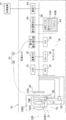
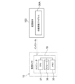
一例として図1に示すように、監視システム2は、監視カメラ10及び管理装置11を備えている。監視システム2は、本開示の技術に係る「撮像システム」及び「撮像支援システム」の一例であり、監視カメラ10は、本開示の技術に係る「撮像装置」の一例である。 [First Embodiment]
As an example, as shown in FIG. 1, thesurveillance system 2 includes a surveillance camera 10 and a management device 11. The surveillance system 2 is an example of the "imaging system" and the "imaging support system" according to the technology of the present disclosure, and the surveillance camera 10 is an example of the "imaging apparatus" according to the technology of the present disclosure.
一例として図1に示すように、監視システム2は、監視カメラ10及び管理装置11を備えている。監視システム2は、本開示の技術に係る「撮像システム」及び「撮像支援システム」の一例であり、監視カメラ10は、本開示の技術に係る「撮像装置」の一例である。 [First Embodiment]
As an example, as shown in FIG. 1, the
監視カメラ10は、屋内外の柱、壁又は建物の一部(例えば、屋上)等に、後述する旋回機構16を介して設置され、被写体である監視対象を撮像し、撮像することで動画像を生成する。動画像には、撮像することで得られた複数フレームの画像が含まれている。監視カメラ10は、撮像することで得た動画像を、通信ライン12を介して管理装置11に送信する。
The surveillance camera 10 is installed on a pillar, wall, part of a building (for example, a rooftop) indoors or outdoors via a swivel mechanism 16 described later, and images a surveillance object as a subject to obtain a moving image. To generate. The moving image includes a multi-frame image obtained by imaging. The surveillance camera 10 transmits the moving image obtained by capturing the image to the management device 11 via the communication line 12.
管理装置11は、ディスプレイ13及び二次記憶装置14を備えている。ディスプレイ13としては、例えば、液晶ディスプレイ又は有機ELディスプレイ等が挙げられる。なお、ディスプレイ13は、本開示の技術に係る「表示部(ディスプレイ)」の一例である。
The management device 11 includes a display 13 and a secondary storage device 14. Examples of the display 13 include a liquid crystal display and an organic EL display. The display 13 is an example of a "display unit (display)" according to the technique of the present disclosure.
二次記憶装置14の一例としては、HDDが挙げられる。二次記憶装置14は、HDDではなく、フラッシュメモリ、SSD、又はEEPROMなどの不揮発性のメモリであればよい。なお、二次記憶装置14は、本開示の技術に係る「記憶部(記憶装置)」の一例である。
An HDD is an example of the secondary storage device 14. The secondary storage device 14 may be a non-volatile memory such as a flash memory, SSD, or EEPROM instead of an HDD. The secondary storage device 14 is an example of a “storage unit (storage device)” according to the technique of the present disclosure.
管理装置11では、監視カメラ10によって送信された動画像が受信され、受信された動画像がディスプレイ13に表示されたり、二次記憶装置14に記憶されたりする。
In the management device 11, the moving image transmitted by the surveillance camera 10 is received, and the received moving image is displayed on the display 13 or stored in the secondary storage device 14.
旋回機構16には、監視カメラ10が取り付けられる。旋回機構16は、監視カメラ10を旋回可能とする。具体的には、旋回機構16は、第1の方向と、第1の方向と交差する第2の方向とに監視カメラ10を旋回可能な2軸旋回機構である。一例として図2に示すように、旋回機構16は、ピッチ軸PAを中心軸とした旋回方向(以下、「ピッチ方向」とも称する)に監視カメラ10を旋回可能とする。また、一例として図3に示すように、旋回機構16は、ヨー軸YAを中心軸とした旋回方向(以下、「ヨー方向」と称する)に監視カメラ10を旋回可能とする。旋回機構16は、本開示の技術に係る「旋回機構」の一例である。また、「ピッチ方向」は、本開示の技術に係る「第1方向」の一例であり、ヨー方向は、本開示の技術に係る「第2方向」の一例である。なお、本実施形態では、旋回機構16として、2軸旋回機構を例示しているが、本開示の技術はこれに限定されず、3軸旋回機構を適用しても本開示の技術は成立する。
A surveillance camera 10 is attached to the swivel mechanism 16. The swivel mechanism 16 enables the surveillance camera 10 to swivel. Specifically, the swivel mechanism 16 is a biaxial swivel mechanism capable of swiveling the surveillance camera 10 in a first direction and a second direction intersecting the first direction. As an example, as shown in FIG. 2, the swivel mechanism 16 enables the surveillance camera 10 to swivel in a swivel direction (hereinafter, also referred to as “pitch direction”) with the pitch axis PA as the central axis. Further, as shown in FIG. 3 as an example, the swivel mechanism 16 enables the surveillance camera 10 to swivel in a swivel direction (hereinafter, referred to as “yaw direction”) with the yaw axis YA as the central axis. The swivel mechanism 16 is an example of a "swivel mechanism" according to the technique of the present disclosure. Further, the "pitch direction" is an example of the "first direction" according to the technique of the present disclosure, and the yaw direction is an example of the "second direction" according to the technique of the present disclosure. In the present embodiment, the two-axis swivel mechanism is illustrated as the swivel mechanism 16, but the technique of the present disclosure is not limited to this, and the technique of the present disclosure is established even if the three-axis swivel mechanism is applied. ..
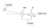
一例として図4に示すように、監視カメラ10は、光学系15及び撮像素子25を備えている。撮像素子25は、光学系15の後段に位置している。光学系15は、対物レンズ15A及びレンズ群15Bを備えている。対物レンズ15A及びレンズ群15Bは、監視対象側(物体側)から撮像素子25の受光面25A側(像側)にかけて、光学系15の光軸OAに沿って、対物レンズ15A及びレンズ群15Bの順に配置されている。レンズ群15Bには、ズームレンズ15B2等が含まれている。ズームレンズ15B2は、移動機構21によって光軸OAに沿って移動可能に支持されている。移動機構21は、ズームレンズ用のモータ(図示省略)から与えられた動力に応じてズームレンズ15B2を光軸OAに沿って移動させる。また、レンズ群15Bには、防振レンズ15B1が含まれている。防振レンズ15B1は、与えられた動力に応じて防振レンズ15B1の光軸に対して垂直方向に変動する。
As an example, as shown in FIG. 4, the surveillance camera 10 includes an optical system 15 and an image sensor 25. The image sensor 25 is located after the optical system 15. The optical system 15 includes an objective lens 15A and a lens group 15B. The objective lens 15A and the lens group 15B are the objective lens 15A and the lens group 15B from the monitoring target side (object side) to the light receiving surface 25A side (image side) of the image pickup element 25 along the optical axis OA of the optical system 15. They are arranged in order. The lens group 15B includes a zoom lens 15B2 and the like. The zoom lens 15B2 is movably supported along the optical axis OA by the moving mechanism 21. The moving mechanism 21 moves the zoom lens 15B2 along the optical axis OA according to the power given by the motor for the zoom lens (not shown). Further, the lens group 15B includes an anti-vibration lens 15B1. The anti-vibration lens 15B1 fluctuates in the direction perpendicular to the optical axis of the anti-vibration lens 15B1 according to the applied power.
このように構成された光学系15によって、監視対象を示す監視対象光は、受光面25Aに結像される。なお、撮像素子25は、本開示の技術に係る「撮像素子」の一例である。
With the optical system 15 configured in this way, the monitoring target light indicating the monitoring target is imaged on the light receiving surface 25A. The image sensor 25 is an example of the "image sensor" according to the technique of the present disclosure.
ところで、監視カメラ10に与えられる振動には、屋外であれば、自動車の通行による振動、風による振動、及び道路工事による振動等があり、屋内であれば、エアコンディショナーの動作による振動、及び人の出入りによる振動等がある。また、監視カメラ10に与えられる振動には、監視カメラ10を旋回機構16により旋回させる間の振動、及び旋回機構16による旋回動作を開始又は停止した際の振動等がある。そのため、監視カメラ10では、監視カメラ10に与えられた振動(以下、単に「振動」とも称する)に起因して振れが生じる。
By the way, the vibration given to the surveillance camera 10 includes vibration caused by the passage of automobiles, vibration caused by wind, vibration caused by road construction, etc. outdoors, and vibration caused by the operation of an air conditioner and people indoors. There is vibration due to the comings and goings of. Further, the vibration given to the surveillance camera 10 includes vibration while the surveillance camera 10 is swiveled by the swivel mechanism 16, vibration when the swivel operation by the swivel mechanism 16 is started or stopped, and the like. Therefore, in the surveillance camera 10, vibration occurs due to the vibration given to the surveillance camera 10 (hereinafter, also simply referred to as “vibration”).
なお、本実施形態において、「振れ」とは、監視カメラ10において、受光面25Aでの被写体像が光軸OAと受光面25Aとの位置関係が変化することで変動する現象を指す。換言すると、「振れ」とは、監視カメラ10に与えられた振動に起因して光軸OAが傾くことによって、受光面25Aに結像されることで得られた光学像が変動する現象とも言える。光軸OAの変動とは、例えば、基準軸(例えば、振れが発生する前の光軸OA)に対して光軸OAが傾くことを意味する。以下では、振動に起因して生じる振れを、単に「振れ」とも称する。
In the present embodiment, the “shake” refers to a phenomenon in which the subject image on the light receiving surface 25A fluctuates due to a change in the positional relationship between the optical axis OA and the light receiving surface 25A in the surveillance camera 10. In other words, "shake" can be said to be a phenomenon in which the optical image obtained by forming an image on the light receiving surface 25A fluctuates due to the tilt of the optical axis OA due to the vibration applied to the surveillance camera 10. .. The fluctuation of the optical axis OA means that the optical axis OA is tilted with respect to the reference axis (for example, the optical axis OA before the runout occurs). Hereinafter, the runout caused by vibration is also simply referred to as “runout”.
そこで、監視カメラ10は、振れ補正部51を備えている。振れ補正部51は、本開示の技術に係る「振れ補正コンポーネント」の一例である。振れ補正部51は、機械式振れ補正部29及び電子式振れ補正部33を有する。振れ補正部51は、振れを補正する。機械式振れ補正部29は、本開示の技術に係る「光学式の振れ補正機構」の一例である。機械式振れ補正部29は、モータ(例えば、ボイスコイルモータ)等の駆動源によって生成された動力を防振レンズに付与することで防振レンズを撮像光学系の光軸に対して垂直な方向に移動させ、これによって振れを補正する機構である。電子式振れ補正部33は、振れ量に基づいて撮像画像に対して画像処理を施すことで振れを補正する。つまり、振れ補正部51は、ハードウェア構成及び/又はソフトウェア構成で機械的又は電子的に振れの補正を行う。ここで、機械的な振れの補正とは、モータ(例えば、ボイスコイルモータ)等の駆動源によって生成された動力を用いて防振レンズ及び/又は撮像素子等の振れ補正素子を機械的に動かすことにより実現される振れの補正を指し、電子的な振れの補正とは、例えば、プロセッサによって画像処理が行われることで実現される振れの補正を指す。なお、本実施形態において、「振れの補正」には、振れを無くすという意味の他に、振れを低減するという意味も含まれる。
Therefore, the surveillance camera 10 is provided with a runout correction unit 51. The runout correction unit 51 is an example of a “shake correction component” according to the technique of the present disclosure. The runout correction unit 51 includes a mechanical runout correction unit 29 and an electronic runout correction unit 33. The runout correction unit 51 corrects the runout. The mechanical runout correction unit 29 is an example of an “optical runout correction mechanism” according to the technique of the present disclosure. The mechanical shake correction unit 29 applies power generated by a drive source such as a motor (for example, a voice coil motor) to the vibration-proof lens in a direction perpendicular to the optical axis of the image pickup optical system. It is a mechanism that corrects the runout by moving it to. The electronic runout correction unit 33 corrects runout by performing image processing on the captured image based on the runout amount. That is, the runout correction unit 51 mechanically or electronically corrects the runout in the hardware configuration and / or the software configuration. Here, mechanical shake correction means that a shake correction element such as an anti-vibration lens and / or an image sensor is mechanically moved by using a power generated by a drive source such as a motor (for example, a voice coil motor). This refers to the runout correction realized by the above, and the electronic runout correction refers to, for example, the runout correction realized by performing image processing by a processor. In the present embodiment, the "correction of runout" includes not only the meaning of eliminating the runout but also the meaning of reducing the runout.
機械式振れ補正部29は、防振レンズ15B1、アクチュエータ17、ドライバ23、及び位置検出センサ39を備えている。
The mechanical shake correction unit 29 includes a vibration isolation lens 15B1, an actuator 17, a driver 23, and a position detection sensor 39.
機械式振れ補正部29による振れの補正方法としては、周知の種々の方法を採用することができる。本実施形態では、振れの補正方法として、振れ量検出センサ40(後述)によって検出された振れ量に基づいて防振レンズ15B1を移動させることで振れを補正する方法が採用されている。具体的には、振れを打ち消す方向に、振れを打ち消す量だけ防振レンズ15B1を移動させることで振れの補正が行われるようにしている。
As a runout correction method by the mechanical runout correction unit 29, various well-known methods can be adopted. In the present embodiment, as a runout correction method, a method of correcting runout by moving the anti-vibration lens 15B1 based on the runout amount detected by the runout amount detection sensor 40 (described later) is adopted. Specifically, the vibration correction is performed by moving the anti-vibration lens 15B1 by the amount of the vibration canceling direction in the direction of canceling the vibration.
防振レンズ15B1にはアクチュエータ17が取り付けられている。アクチュエータ17は、ボイスコイルモータが搭載されたシフト機構であり、ボイスコイルモータを駆動させることで防振レンズ15B1を、防振レンズ15B1の光軸に対して垂直方向に変動させる。なお、ここでは、アクチュエータ17としては、ボイスコイルモータが搭載されたシフト機構が採用されているが、本開示の技術はこれに限定されず、ボイスコイルモータに代えて、ステッピングモータ又はピエゾ素子等の他の動力源を適用してもよい。
An actuator 17 is attached to the anti-vibration lens 15B1. The actuator 17 is a shift mechanism on which a voice coil motor is mounted. By driving the voice coil motor, the anti-vibration lens 15B1 is changed in a direction perpendicular to the optical axis of the anti-vibration lens 15B1. Here, as the actuator 17, a shift mechanism equipped with a voice coil motor is adopted, but the technique of the present disclosure is not limited to this, and instead of the voice coil motor, a stepping motor, a piezo element, or the like is used. Other power sources may be applied.
アクチュエータ17は、ドライバ23により制御される。アクチュエータ17がドライバ23の制御下で駆動することで、防振レンズ15B1の位置が光軸OAに対して機械的に変動する。
The actuator 17 is controlled by the driver 23. When the actuator 17 is driven under the control of the driver 23, the position of the anti-vibration lens 15B1 mechanically fluctuates with respect to the optical axis OA.
位置検出センサ39は、防振レンズ15B1の現在位置を検出し、検出した現在位置を示す位置信号を出力する。ここでは、位置検出センサ39の一例として、ホール素子を含むデバイスが採用されている。ここで、防振レンズ15B1の現在位置とは、防振レンズ二次元平面内の現在位置を指す。防振レンズ二次元平面とは、防振レンズ15B1の光軸に対して垂直な二次元平面を指す。なお、本実施形態では、位置検出センサ39の一例として、ホール素子を含むデバイスが採用されているが、本開示の技術はこれに限定されず、ホール素子に代えて、磁気センサ又はフォトセンサなどを採用してもよい。
The position detection sensor 39 detects the current position of the anti-vibration lens 15B1 and outputs a position signal indicating the detected current position. Here, as an example of the position detection sensor 39, a device including a Hall element is adopted. Here, the current position of the anti-vibration lens 15B1 refers to the current position in the two-dimensional plane of the anti-vibration lens. The anti-vibration lens two-dimensional plane refers to a two-dimensional plane perpendicular to the optical axis of the anti-vibration lens 15B1. In the present embodiment, a device including a Hall element is adopted as an example of the position detection sensor 39, but the technique of the present disclosure is not limited to this, and instead of the Hall element, a magnetic sensor, a photo sensor, or the like is used. May be adopted.
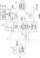
監視カメラ10は、コンピュータ19、DSP31、画像メモリ32、電子式振れ補正部33、通信I/F34、振れ量検出センサ40、及びUI系デバイス43を備えている。コンピュータ19は、メモリ35、ストレージ36、及びCPU37を備えている。電子式振れ補正部33は、本開示の技術に係る「電子式の振れ補正部」の一例である。また、CPU37は、本開示の技術に係る「撮像支援装置」の一例である。
The surveillance camera 10 includes a computer 19, a DSP 31, an image memory 32, an electronic shake correction unit 33, a communication I / F 34, a runout detection sensor 40, and a UI device 43. The computer 19 includes a memory 35, a storage 36, and a CPU 37. The electronic runout correction unit 33 is an example of an "electronic runout correction unit" according to the technique of the present disclosure. Further, the CPU 37 is an example of the "imaging support device" according to the technique of the present disclosure.
撮像素子25、DSP31、画像メモリ32、電子式振れ補正部33、通信I/F34、メモリ35、ストレージ36、CPU37、振れ量検出センサ40、及びUI系デバイス43は、バス38に接続されている。また、ドライバ23もバス38に接続されている。なお、図4に示す例では、図示の都合上、バス38として1本のバスが図示されているが、複数本のバスであってもよい。バス38は、シリアルバスであってもよいし、データバス、アドレスバス、及びコントロールバス等を含むパラレルバスであってもよい。
The image sensor 25, DSP 31, image memory 32, electronic runout correction unit 33, communication I / F 34, memory 35, storage 36, CPU 37, runout detection sensor 40, and UI device 43 are connected to the bus 38. .. The driver 23 is also connected to the bus 38. In the example shown in FIG. 4, one bus is shown as the bus 38 for convenience of illustration, but a plurality of buses may be used. The bus 38 may be a serial bus or a parallel bus including a data bus, an address bus, a control bus, and the like.
メモリ35は、各種情報を一時的に記憶し、ワークメモリとして用いられる。メモリ35の一例としては、RAMが挙げられるが、これに限らず、他の種類の記憶装置であってもよい。ストレージ36は、不揮発性の記憶装置である。ここでは、ストレージ36の一例として、フラッシュメモリが採用されている。フラッシュメモリはあくまでも一例に過ぎず、ストレージ36としては、例えば、フラッシュメモリに代えて、又は、フラッシュメモリと併せて、磁気抵抗メモリ及び/又は強誘電体メモリなどの各種の不揮発性メモリが挙げられる。また、不揮発性の記憶装置は、EEPROM、HDD、及び/又はSSD等であってもよい。ストレージ36には、監視カメラ10用の各種プログラムが記憶されている。CPU37は、ストレージ36から各種プログラムを読み出し、読み出した各種プログラムをメモリ35上で実行することで監視カメラ10の全体を制御する。
The memory 35 temporarily stores various information and is used as a work memory. An example of the memory 35 is RAM, but the memory 35 is not limited to this, and other types of storage devices may be used. The storage 36 is a non-volatile storage device. Here, a flash memory is adopted as an example of the storage 36. The flash memory is merely an example, and examples of the storage 36 include various non-volatile memories such as a magnetoresistive memory and / or a ferroelectric memory in place of the flash memory or in combination with the flash memory. .. Further, the non-volatile storage device may be EEPROM, HDD, and / or SSD or the like. Various programs for the surveillance camera 10 are stored in the storage 36. The CPU 37 reads various programs from the storage 36 and executes the read various programs on the memory 35 to control the entire surveillance camera 10.
撮像素子25は、CMOSイメージセンサである。撮像素子25は、CPU37の指示の下、既定のフレームレートで監視対象を撮像する。ここで言う「既定のフレームレート」とは、例えば、数十フレーム/秒から数百フレーム/秒を指す。なお、撮像素子25そのものにも制御装置(撮像素子制御装置)が内蔵されていても良く、その場合はCPU37が出力する撮像指示に応じて撮像素子25内部の詳細な制御を撮像素子制御装置が行う。また、撮像素子25が、DSP31の指示の下に既定のフレームレートで対象被写体を撮像しても良く、この場合は、DSP31が出力する撮像指示に応じて撮像素子25内部の詳細な制御を撮像素子制御装置が行う。なお、DSP31はISPと呼ばれることもある。
The image sensor 25 is a CMOS image sensor. The image sensor 25 images the monitored object at a predetermined frame rate under the instruction of the CPU 37. The "default frame rate" here refers to, for example, tens of frames / second to hundreds of frames / second. The image sensor 25 itself may also have a built-in control device (image sensor control device). In that case, the image sensor control device controls the inside of the image sensor 25 in detail according to the image pickup instruction output by the CPU 37. Do. Further, the image sensor 25 may image the target subject at a predetermined frame rate under the instruction of the DSP 31, and in this case, the detailed control inside the image sensor 25 is imaged according to the image pickup instruction output by the DSP 31. It is performed by the element control device. The DSP 31 is sometimes called an ISP.
受光面25Aは、マトリクス状に配置された複数の感光画素(図示省略)によって形成されている。撮像素子25では、各感光画素が露光され、感光画素毎に光電変換が行われる。感光画素毎に光電変換が行われることで得られた電荷は、監視対象を示すアナログの撮像信号である。ここでは、複数の感光画素として、可視光に感度を有する複数の光電変換素子(一例として、カラーフィルタが配置された光電変換素子)が採用されている。撮像素子25において、複数の光電変換素子としては、R(赤)の光に感度を有する光電変換素子(例えば、Rに対応するRフィルタが配置された光電変換素子)、G(緑)の光に感度を有する光電変換素子(例えば、Gに対応するGフィルタが配置された光電変換素子)、及びB(青)の光に感度を有する光電変換素子(例えば、Bに対応するBフィルタが配置された光電変換素子)が採用されている。監視カメラ10では、これらの感光画素を用いることによって、可視光(例えば、約700ナノメートル以下の短波長側の光)に基づく撮像が行われている。但し、本実施形態はこれに限定されず、赤外光(例えば、約700ナノメートルよりも長波長側の光)に基づく撮像が行われるようにしてもよい。この場合、複数の感光画素として、赤外光に感度を有する複数の光電変換素子を用いればよい。特に、SWIRについての撮像に対しては、例えば、InGaAsセンサ及び/又はタイプ2型量子井戸(T2SL;Simulation of Type-II Quantum Well)センサ等を用いればよい。
The light receiving surface 25A is formed by a plurality of photosensitive pixels (not shown) arranged in a matrix. In the image sensor 25, each photosensitive pixel is exposed, and photoelectric conversion is performed for each photosensitive pixel. The electric charge obtained by performing photoelectric conversion for each photosensitive pixel is an analog imaging signal indicating a monitoring target. Here, as the plurality of photosensitive pixels, a plurality of photoelectric conversion elements having sensitivity to visible light (for example, a photoelectric conversion element in which a color filter is arranged) are adopted. In the image pickup element 25, the plurality of photoelectric conversion elements include a photoelectric conversion element having sensitivity to R (red) light (for example, a photoelectric conversion element in which an R filter corresponding to R is arranged) and G (green) light. A photoelectric conversion element having sensitivity to (for example, a photoelectric conversion element in which a G filter corresponding to G is arranged) and a photoelectric conversion element having sensitivity to B (blue) light (for example, a B filter corresponding to B are arranged). The photoelectric conversion element) has been adopted. By using these photosensitive pixels, the surveillance camera 10 performs imaging based on visible light (for example, light on the short wavelength side of about 700 nanometers or less). However, the present embodiment is not limited to this, and imaging may be performed based on infrared light (for example, light having a wavelength longer than about 700 nanometers). In this case, as the plurality of photosensitive pixels, a plurality of photoelectric conversion elements having sensitivity to infrared light may be used. In particular, for imaging of SWIR, for example, an InGaAs sensor and / or a type 2 quantum well (T2SL; Simulation of Type-II Quantum Well) sensor or the like may be used.
撮像素子25は、アナログの撮像信号に対してA/D変換等の信号処理を行い、デジタルの撮像信号であるデジタル画像を生成する。撮像素子25は、バス38を介してDSP31に接続されており、生成したデジタル画像を、バス38を介してフレーム単位でDSP31に出力する。ここで、デジタル画像は、本開示の技術に係る「撮像画像」の一例である。
The image pickup device 25 performs signal processing such as A / D conversion on the analog image pickup signal to generate a digital image which is a digital image pickup signal. The image sensor 25 is connected to the DSP 31 via the bus 38, and outputs the generated digital image to the DSP 31 in frame units via the bus 38. Here, the digital image is an example of the "captured image" according to the technique of the present disclosure.
なお、ここでは、撮像素子25の一例としてCMOSイメージセンサを挙げて説明しているが、本開示の技術はこれに限定されず、撮像素子25としてCCDイメージセンサを適用してもよい。この場合、撮像素子25はCCDドライバ内蔵のAFE(図示省略)を介してバス38に接続され、AFEは、撮像素子25によって得られたアナログの撮像信号に対してA/D変換等の信号処理を施すことでデジタル画像を生成し、生成したデジタル画像をDSP31に出力する。CCDイメージセンサはAFEに内蔵されたCCDドライバによって駆動される。もちろんCCDドライバは単独に設けられても良い。
Although the CMOS image sensor is described as an example of the image sensor 25 here, the technique of the present disclosure is not limited to this, and a CCD image sensor may be applied as the image sensor 25. In this case, the image sensor 25 is connected to the bus 38 via an AFE (not shown) built in the CCD driver, and the AFE performs signal processing such as A / D conversion on the analog image sensor obtained by the image sensor 25. Is applied to generate a digital image, and the generated digital image is output to the DSP 31. The CCD image sensor is driven by the CCD driver built into the AFE. Of course, the CCD driver may be provided independently.
DSP31は、デジタル画像に対して、各種デジタル信号処理を施す。各種デジタル信号処理とは、例えば、デモザイク処理、ノイズ除去処理、階調補正処理、及び色補正処理等を指す。
DSP31 performs various digital signal processing on digital images. The various digital signal processes refer to, for example, demosaic processing, noise removal processing, gradation correction processing, color correction processing, and the like.
DSP31は、1フレーム毎に、デジタル信号処理後のデジタル画像を画像メモリ32に出力する。画像メモリ32は、DSP31からのデジタル画像を記憶する。なお、以下では、説明の便宜上、画像メモリ32に記憶されたデジタル画像を「撮像画像」とも称する。
The DSP 31 outputs a digital image after digital signal processing to the image memory 32 for each frame. The image memory 32 stores a digital image from the DSP 31. In the following, for convenience of explanation, the digital image stored in the image memory 32 is also referred to as an “captured image”.
振れ量検出センサ40は、例えば、ジャイロセンサを含むデバイスであり、監視カメラ10の振れ量を検出する。換言すると、振れ量検出センサ40は、一対の軸方向の各々について振れ量を検出する。ジャイロセンサは、ピッチ軸PA、ヨー軸YA、及びロール軸RA(光軸OAに平行な軸)の各軸(図1参照)周りの回転振れの量を検出する。振れ量検出センサ40は、ジャイロセンサによって検出されたピッチ軸PA周りの回転振れの量及びヨー軸YA周りの回転振れの量をピッチ軸PA及びヨー軸YAに平行な2次元状の面内での振れ量に変換することで、監視カメラ10の振れ量を検出する。
The runout detection sensor 40 is, for example, a device including a gyro sensor, and detects the runout of the surveillance camera 10. In other words, the runout detection sensor 40 detects the runout amount in each of the pair of axial directions. The gyro sensor detects the amount of rotational runout around each axis (see FIG. 1) of the pitch axis PA, the yaw axis YA, and the roll axis RA (the axis parallel to the optical axis OA). The runout detection sensor 40 measures the amount of rotational runout around the pitch axis PA and the amount of rotational runout around the yaw axis YA detected by the gyro sensor in a two-dimensional plane parallel to the pitch axis PA and the yaw axis YA. The amount of runout of the surveillance camera 10 is detected by converting it into the amount of runout of.
ここでは、振れ量検出センサ40の一例としてジャイロセンサを挙げているが、これはあくまでも一例であり、振れ量検出センサ40は、加速度センサであってもよい。加速度センサは、ピッチ軸PAとヨー軸YAに平行な2次元状の面内での振れ量を検出する。振れ量検出センサ40は、検出した振れ量をCPU37に出力する。
Here, the gyro sensor is mentioned as an example of the runout detection sensor 40, but this is just an example, and the runout detection sensor 40 may be an acceleration sensor. The accelerometer detects the amount of runout in a two-dimensional plane parallel to the pitch axis PA and the yaw axis YA. The runout detection sensor 40 outputs the detected runout amount to the CPU 37.
また、ここでは、振れ量検出センサ40という物理的なセンサによって振れ量が検出される形態例を挙げているが、本開示の技術はこれに限定されない。例えば、画像メモリ32に記憶された時系列的に前後する撮像画像を比較することで得た動きベクトルを振れ量として用いてもよい。また、物理的なセンサによって検出された振れ量と、画像処理によって得られた動きベクトルとに基づいて最終的に使用される振れ量とが導出されるようにしてもよい。
Further, here, a form example in which the runout amount is detected by a physical sensor called the runout amount detection sensor 40 is given, but the technique of the present disclosure is not limited to this. For example, the motion vector obtained by comparing the captured images stored in the image memory 32 in time series before and after may be used as the amount of runout. Further, the amount of runout detected by the physical sensor and the amount of runout finally used may be derived based on the motion vector obtained by the image processing.
CPU37は、振れ量検出センサ40によって検出された振れ量を取得し、取得した振れ量に基づいて機械式振れ補正部29及び電子式振れ補正部33を制御する。振れ量検出センサ40によって検出された振れ量は、機械式振れ補正部29及び電子式振れ補正部33の各々による振れの補正に用いられる。機械式振れ補正部29及び電子式振れ補正部33は、振れ量検出センサ40によって検出された振れ量に従って振れを補正する。
The CPU 37 acquires the amount of runout detected by the runout amount detection sensor 40, and controls the mechanical runout correction unit 29 and the electronic runout correction unit 33 based on the acquired runout amount. The amount of runout detected by the runout amount detection sensor 40 is used for runout correction by each of the mechanical runout correction unit 29 and the electronic runout correction unit 33. The mechanical runout correction unit 29 and the electronic runout correction unit 33 correct the runout according to the runout amount detected by the runout amount detection sensor 40.
電子式振れ補正部33は、ASICを含むデバイスである。電子式振れ補正部33は、振れ量検出センサ40によって検出された振れ量に基づいて、画像メモリ32内の撮像画像に対して画像処理を施すことで振れを補正する。
The electronic runout correction unit 33 is a device including an ASIC. The electronic runout correction unit 33 corrects runout by performing image processing on the captured image in the image memory 32 based on the runout amount detected by the runout amount detection sensor 40.
なお、ここでは、電子式振れ補正部33として、ASICを含むデバイスを例示しているが、本開示の技術はこれに限定されるものではなく、例えば、FPGA又はPLDを含むデバイスであってもよい。また、例えば、電子式振れ補正部33は、ASIC、FPGA、及びPLDのうちの複数を含むデバイスであってもよい。また、電子式振れ補正部33として、CPU、ストレージ、及びメモリを含むコンピュータが採用されてもよい。CPUは、単数であってもよいし、複数であってもよい。また、電子式振れ補正部33は、ハードウェア構成及びソフトウェア構成の組み合わせによって実現されてもよい。
Here, a device including an ASIC is illustrated as the electronic runout correction unit 33, but the technique of the present disclosure is not limited to this, and for example, a device including an FPGA or PLD may be used. Good. Further, for example, the electronic runout correction unit 33 may be a device including a plurality of ASICs, FPGAs, and PLDs. Further, as the electronic runout correction unit 33, a computer including a CPU, a storage, and a memory may be adopted. The number of CPUs may be singular or plural. Further, the electronic runout correction unit 33 may be realized by a combination of a hardware configuration and a software configuration.
通信I/F34は、例えば、ネットワークインターフェースであり、ネットワークを介して、管理装置11との間で各種情報の伝送制御を行う。ネットワークの一例としては、インターネット又は公衆通信網等のWANが挙げられる。監視カメラ10と管理装置11との間の通信を司る。
The communication I / F 34 is, for example, a network interface, and controls transmission of various information to and from the management device 11 via the network. An example of a network is a WAN such as the Internet or a public communication network. It controls communication between the surveillance camera 10 and the management device 11.
UI系デバイス43は、受付デバイス43A及びディスプレイ43Bを備えている。受付デバイス43Aは、例えば、ハードキー及びタッチパネル等であり、監視システム2の使用者等(以下、単に「使用者等」とも称する)からの各種指示を受け付ける。CPU37は、受付デバイス43Aによって受け付けられた各種指示を取得し、取得した指示に従って動作する。
The UI device 43 includes a reception device 43A and a display 43B. The reception device 43A is, for example, a hard key, a touch panel, or the like, and receives various instructions from a user or the like of the monitoring system 2 (hereinafter, also simply referred to as “user or the like”). The CPU 37 acquires various instructions received by the reception device 43A and operates according to the acquired instructions.
ディスプレイ43Bは、CPU37の制御下で、各種情報を表示する。ディスプレイ43Bに表示される各種情報としては、例えば、受付デバイス43Aによって受け付けられた各種指示の内容、及び撮像画像等が挙げられる。
The display 43B displays various information under the control of the CPU 37. Examples of various information displayed on the display 43B include the contents of various instructions received by the reception device 43A, captured images, and the like.
一例として図5に示すように、旋回機構16は、ヨー軸旋回機構71、ピッチ軸旋回機構72、モータ73、モータ74、ドライバ75、及びドライバ76を備えている。ヨー軸旋回機構71は、監視カメラ10をヨー方向に旋回させる。モータ73は、ドライバ75の制御下で駆動することで動力を生成する。ヨー軸旋回機構71は、モータ73によって生成された動力を受けることで監視カメラ10をヨー方向に旋回させる。モータ74は、ドライバ76の制御下で駆動することで動力を生成する。ピッチ軸旋回機構72は、モータ74によって生成された動力を受けることで監視カメラ10をピッチ方向に旋回させる。
As an example, as shown in FIG. 5, the swivel mechanism 16 includes a yaw shaft swivel mechanism 71, a pitch shaft swivel mechanism 72, a motor 73, a motor 74, a driver 75, and a driver 76. The yaw axis swivel mechanism 71 swivels the surveillance camera 10 in the yaw direction. The motor 73 generates power by driving under the control of the driver 75. The yaw axis swivel mechanism 71 swivels the surveillance camera 10 in the yaw direction by receiving the power generated by the motor 73. The motor 74 generates power by driving under the control of the driver 76. The pitch axis swivel mechanism 72 swivels the surveillance camera 10 in the pitch direction by receiving the power generated by the motor 74.
一例として図5に示すように、管理装置11は、ディスプレイ13、二次記憶装置14、制御装置60、受付デバイス62、及び通信I/F66~68を備えている。制御装置60は、CPU60A、ストレージ60B、及びメモリ60Cを備えている。受付デバイス62、ディスプレイ13、CPU60A、ストレージ60B、メモリ60C、及び通信I/F66~68の各々は、バス70に接続されている。なお、図5に示す例では、図示の都合上、バス70として1本のバスが図示されているが、複数本のバスであってもよい。バス70は、シリアルバスであってもよいし、データバス、アドレスバス、及びコントロールバス等を含むパラレルバスであってもよい。
As an example, as shown in FIG. 5, the management device 11 includes a display 13, a secondary storage device 14, a control device 60, a reception device 62, and communication I / F 66 to 68. The control device 60 includes a CPU 60A, a storage 60B, and a memory 60C. Each of the reception device 62, the display 13, the CPU 60A, the storage 60B, the memory 60C, and the communication I / F 66 to 68 is connected to the bus 70. In the example shown in FIG. 5, one bus is shown as the bus 70 for convenience of illustration, but a plurality of buses may be used. The bus 70 may be a serial bus or a parallel bus including a data bus, an address bus, a control bus, and the like.
メモリ60Cは、各種情報を一時的に記憶し、ワークメモリとして用いられる。メモリ60Cの一例としては、RAMが挙げられるが、これに限らず、他の種類の記憶装置であってもよい。ストレージ60Bは、不揮発性の記憶装置である。ここでは、ストレージ60Bの一例として、フラッシュメモリが採用されている。フラッシュメモリはあくまでも一例に過ぎず、ストレージ60Bとしては、例えば、フラッシュメモリに代えて、又は、フラッシュメモリと併せて、磁気抵抗メモリ及び/又は強誘電体メモリなどの各種の不揮発性メモリが挙げられる。また、不揮発性の記憶装置は、EEPROM、HDD、及び/又はSSD等であってもよい。ストレージ60Bには、管理装置11用の各種プログラム(以下、単に「管理装置用プログラム」と称する)が記憶されている。CPU60Aは、ストレージ60Bから管理装置用プログラムを読み出し、読み出した管理装置用プログラムをメモリ60C上で実行することで管理装置11の全体を制御する。
The memory 60C temporarily stores various information and is used as a work memory. An example of the memory 60C is RAM, but the present invention is not limited to this, and other types of storage devices may be used. The storage 60B is a non-volatile storage device. Here, a flash memory is adopted as an example of the storage 60B. The flash memory is merely an example, and examples of the storage 60B include various non-volatile memories such as a magnetoresistive memory and / or a ferroelectric memory in place of the flash memory or in combination with the flash memory. .. Further, the non-volatile storage device may be EEPROM, HDD, and / or SSD or the like. Various programs for the management device 11 (hereinafter, simply referred to as “management device programs”) are stored in the storage 60B. The CPU 60A reads the management device program from the storage 60B and executes the read management device program on the memory 60C to control the entire management device 11.
通信I/F66は、例えば、ネットワークインターフェースである。通信I/F66は、ネットワークを介して、監視カメラ10の通信I/F34に対して通信可能に接続されており、監視カメラ10との間で各種情報の伝送制御を行う。例えば、通信I/F66は、監視カメラ10に対して撮像画像の送信を要求し、撮像画像の送信の要求に応じて監視カメラ10の通信I/F34から送信された撮像画像を受信する。
Communication I / F66 is, for example, a network interface. The communication I / F 66 is communicably connected to the communication I / F 34 of the surveillance camera 10 via a network, and controls transmission of various information with the surveillance camera 10. For example, the communication I / F 66 requests the surveillance camera 10 to transmit the captured image, and receives the captured image transmitted from the communication I / F 34 of the surveillance camera 10 in response to the request for transmitting the captured image.
通信I/F67及び68は、例えば、ネットワークインターフェースである。通信I/F67は、ネットワークを介して、ドライバ75に対して通信可能に接続されている。CPU60Aは、通信I/F67及びドライバ75を介して、モータ73を制御することで、ヨー軸旋回機構71の旋回動作を制御する。通信I/F68は、ネットワークを介して、ドライバ76に対して通信可能に接続されている。CPU60Aは、通信I/F68及びドライバ76を介して、モータ74を制御することで、ピッチ軸旋回機構72の旋回動作を制御する。
Communication I / F 67 and 68 are, for example, network interfaces. The communication I / F 67 is communicably connected to the driver 75 via the network. The CPU 60A controls the turning operation of the yaw axis turning mechanism 71 by controlling the motor 73 via the communication I / F 67 and the driver 75. The communication I / F 68 is communicably connected to the driver 76 via the network. The CPU 60A controls the turning operation of the pitch axis turning mechanism 72 by controlling the motor 74 via the communication I / F 68 and the driver 76.
受付デバイス62は、例えば、キーボード、マウス、及びタッチパネル等であり、使用者等からの各種指示を受け付ける。CPU60Aは、受付デバイス62によって受け付けられた各種指示を取得し、取得した指示に従って動作する。
The reception device 62 is, for example, a keyboard, a mouse, a touch panel, or the like, and receives various instructions from the user or the like. The CPU 60A acquires various instructions received by the receiving device 62 and operates according to the acquired instructions.
ディスプレイ13は、CPU60Aの制御下で、各種情報を表示する。ディスプレイ13に表示される各種情報としては、例えば、受付デバイス62によって受け付けられた各種指示の内容、及び通信I/F66によって受信された撮像画像等が挙げられる。
The display 13 displays various information under the control of the CPU 60A. Examples of the various information displayed on the display 13 include the contents of various instructions received by the reception device 62, the captured image received by the communication I / F 66, and the like.
二次記憶装置14は、CPU60Aの制御下で、各種情報を記憶する。二次記憶装置14に記憶される各種情報としては、例えば、通信I/F66によって受信された撮像画像等が挙げられる。
The secondary storage device 14 stores various information under the control of the CPU 60A. Examples of various information stored in the secondary storage device 14 include captured images received by the communication I / F 66.
このように、制御装置60は、通信I/F66によって受信された撮像画像をディスプレイ13に対して表示させる制御、及び通信I/F66によって受信された撮像画像を二次記憶装置14に対して記憶させる制御を行う。ディスプレイ13に表示される撮像画像は、本開示の技術に係る「対象被写体画像の位置の調整結果が反映された画像」の一例である。また、二次記憶装置14に記憶される撮像画像は、本開示の技術に係る「画像データ」の一例である。
In this way, the control device 60 controls the display 13 to display the captured image received by the communication I / F 66, and stores the captured image received by the communication I / F 66 in the secondary storage device 14. Control to make it. The captured image displayed on the display 13 is an example of "an image reflecting the adjustment result of the position of the target subject image" according to the technique of the present disclosure. The captured image stored in the secondary storage device 14 is an example of "image data" according to the technique of the present disclosure.
なお、ここでは、撮像画像をディスプレイ13に対して表示させ、かつ、通信I/F66によって受信された撮像画像を二次記憶装置14に対して記憶させるようにしているが、本開示の技術はこれに限定されない。例えば、撮像画像のディスプレイ13に対する表示と撮像画像の二次記憶装置14に対する記憶との何れかが行われるようにしてもよい。
Here, the captured image is displayed on the display 13 and the captured image received by the communication I / F 66 is stored in the secondary storage device 14, but the technique of the present disclosure is described. Not limited to this. For example, either the display of the captured image on the display 13 or the storage of the captured image in the secondary storage device 14 may be performed.
ところで、監視カメラ10には、対象被写体を追尾する機能(以下、「追尾機能」とも称する)が設けられている。追尾機能によって対象被写体を追尾する場合、対象被写体の移動に備えて、撮像領域に含まれる対象被写体(例えば、特定の人物)を示す対象被写体画像の撮像画像内での位置を撮像画像内の既定位置に合わせておくことが好ましい。例えば、対象被写体画像の位置を撮像画像の中心位置に合わせておけば、種々の方向への対象被写体画像の位置の変化に対応が可能となるからである。
By the way, the surveillance camera 10 is provided with a function of tracking a target subject (hereinafter, also referred to as a "tracking function"). When tracking the target subject by the tracking function, the position in the captured image of the target subject image indicating the target subject (for example, a specific person) included in the imaging area is set as the default in the captured image in preparation for the movement of the target subject. It is preferable to adjust to the position. For example, if the position of the target subject image is aligned with the center position of the captured image, it is possible to respond to changes in the position of the target subject image in various directions.
そこで、対象被写体画像の撮像画像内での位置を撮像画像内の既定位置に合わせるために、一例として図6に示すように、ストレージ36には、位置調整プログラム36Aが記憶されており、位置調整プログラム36AがCPU37によって実行される。具体的には、CPU37が、ストレージ36から位置調整プログラム36Aを読み出し、読み出した位置調整プログラム36Aをメモリ35上で実行することで、撮像素子25を含む監視カメラ10による撮像を支援する撮像支援装置として機能する。このように、CPU37は、撮像支援装置として機能することで、監視カメラ10による対象被写体画像の位置を、撮像画像の中心位置(以下、「画像中心位置」とも称する)とした状態下での撮像を支援する。なお、画像中心位置は、本開示の技術に係る「既定位置」及び「特定位置」の一例である。
Therefore, in order to match the position of the target subject image in the captured image with the predetermined position in the captured image, as shown in FIG. 6 as an example, the storage 36 stores the position adjustment program 36A and adjusts the position. Program 36A is executed by CPU 37. Specifically, the CPU 37 reads the position adjustment program 36A from the storage 36 and executes the read position adjustment program 36A on the memory 35 to support imaging by the surveillance camera 10 including the image sensor 25. Functions as. In this way, the CPU 37 functions as an image pickup support device, so that the position of the target subject image by the surveillance camera 10 is taken as the center position of the captured image (hereinafter, also referred to as “image center position”). To support. The image center position is an example of the "default position" and the "specific position" according to the technique of the present disclosure.
監視カメラ10による対象被写体画像の位置を特定位置とした状態下での撮像の支援を実現するために、監視カメラ10は、位置調整部52を備えている。位置調整部52は、旋回機構16と振れ補正部51とを有しており、撮像画像内での対象被写体画像の位置を調整する。CPU37は、位置調整部52を制御することで、監視カメラ10による撮像を支援する。位置調整部52は、本開示の技術に係る「位置調整デバイス」の一例である。
The surveillance camera 10 is provided with a position adjusting unit 52 in order to support imaging in a state where the position of the target subject image is set to a specific position by the surveillance camera 10. The position adjusting unit 52 has a turning mechanism 16 and a runout correction unit 51, and adjusts the position of the target subject image in the captured image. The CPU 37 supports the imaging by the surveillance camera 10 by controlling the position adjusting unit 52. The position adjusting unit 52 is an example of the “position adjusting device” according to the technique of the present disclosure.
また、CPU37は、位置調整部52によって対象被写体画像の位置を画像中心位置に移動させるのに要する移動量を、種々の情報に基づいて導出する。また、CPU37は、導出した移動量を出力する。位置調整部52が移動量に基づいて制御されることで、対象被写体画像の位置を画像中心位置に合わせることができ、対象被写体の追尾が支援される。
Further, the CPU 37 derives the amount of movement required to move the position of the target subject image to the image center position by the position adjusting unit 52 based on various information. Further, the CPU 37 outputs the derived movement amount. By controlling the position adjusting unit 52 based on the amount of movement, the position of the target subject image can be adjusted to the image center position, and the tracking of the target subject is supported.
CPU37は、メモリ35上で位置調整プログラム36Aを実行することで、取得部37A、導出部37B、制御部37C、出力部37D、及び判定部37Eとして動作する。取得部37Aは、本開示の技術に係る「取得部」の一例である。導出部37Bは、本開示の技術に係る「導出部」の一例である。制御部37Cは、本開示の技術に係る「制御部」の一例である。出力部37Dは、本開示の技術に係る「出力部」の一例である。CPU37は、本開示の技術に係る「プロセッサ」の一例であり、メモリ35は、本開示の技術に係る「メモリ」の一例である。
By executing the position adjustment program 36A on the memory 35, the CPU 37 operates as an acquisition unit 37A, a derivation unit 37B, a control unit 37C, an output unit 37D, and a determination unit 37E. The acquisition unit 37A is an example of the “acquisition unit” according to the technique of the present disclosure. The out-licensing unit 37B is an example of the “out-licensing unit” according to the technique of the present disclosure. The control unit 37C is an example of a “control unit” according to the technique of the present disclosure. The output unit 37D is an example of the “output unit” according to the technique of the present disclosure. The CPU 37 is an example of the "processor" according to the technique of the present disclosure, and the memory 35 is an example of the "memory" according to the technique of the present disclosure.
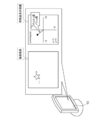
判定部37Eは、画像メモリ32から撮像画像を取得し、取得した撮像画像に対して対象被写体画像についての画像認識を行う。ストレージ36には、画像認識用辞書36Bが記憶されている。画像認識用辞書36Bには、画像認識対象とされる対象被写体画像(例えば、特定の物体を示す画像)が登録されている。判定部37Eは、ストレージ36の画像認識用辞書36Bを参照して撮像画像内に対象被写体画像が含まれているか否かを判定する。また、判定部37Eは、撮像画像内に対象被写体画像が含まれている場合、対象被写体画像の位置が画像中心位置にあるか否かを判定する。
The determination unit 37E acquires a captured image from the image memory 32, and performs image recognition on the target subject image with respect to the acquired captured image. The image recognition dictionary 36B is stored in the storage 36. In the image recognition dictionary 36B, a target subject image (for example, an image showing a specific object) to be image-recognized is registered. The determination unit 37E determines whether or not the target subject image is included in the captured image by referring to the image recognition dictionary 36B of the storage 36. Further, when the target subject image is included in the captured image, the determination unit 37E determines whether or not the position of the target subject image is at the center position of the image.
判定部37Eによって対象被写体画像の位置が画像中心位置にあると判定された場合、取得部37Aは、画像メモリ32から撮像画像を取得し、取得した撮像画像を参照して画像中心位置と対象被写体画像の位置とのずれ量(以下、「画像内ずれ量」とも称する)を取得する。取得部37Aは、画像中心位置に対する対象被写体画像のピクセル座標のずれ量を算出する(図7参照)。ピクセル座標のずれ量は、本開示の技術に係る「画像内ずれ量」の一例である。
When the determination unit 37E determines that the position of the target subject image is at the image center position, the acquisition unit 37A acquires the captured image from the image memory 32, refers to the acquired captured image, and refers to the image center position and the target subject. The amount of deviation from the position of the image (hereinafter, also referred to as "the amount of deviation in the image") is acquired. The acquisition unit 37A calculates the amount of deviation of the pixel coordinates of the target subject image with respect to the image center position (see FIG. 7). The amount of deviation in pixel coordinates is an example of the amount of deviation in an image according to the technique of the present disclosure.
取得部37Aは、監視カメラ10の焦点距離を取得する。具体的には、取得部37Aは、光軸OA上でのズームレンズ15B2の位置を監視しており、監視結果に基づいて焦点距離を導出する。焦点距離の導出は、例えば、監視結果と焦点距離とが対応付けられた焦点距離導出用テーブル、又は、監視結果を独立変数とし、焦点距離を従属変数とした焦点距離導出用演算式が取得部37Aによって用いられることで実現される。
The acquisition unit 37A acquires the focal length of the surveillance camera 10. Specifically, the acquisition unit 37A monitors the position of the zoom lens 15B2 on the optical axis OA, and derives the focal length based on the monitoring result. For the derivation of the focal length, for example, a focal length derivation table in which the monitoring result and the focal length are associated with each other, or a focal length derivation arithmetic expression in which the monitoring result is an independent variable and the focal length is a dependent variable is acquired. It is realized by being used by 37A.
ストレージ36には、振れ補正部51の感度(以下、単に「感度」とも称する)、及び撮像素子25の画素の画素間隔(以下、単に「画素間隔」とも称する)が記憶されている。取得部37Aは、ストレージ36から、感度を取得する。ここで、感度とは、単位振れ角当たりの受光面25Aにおける撮像領域の移動量と、受光面25Aにおける撮像領域を1度動かすために必要な振れ補正部51の可動量との積である。また、取得部37Aは、ストレージ36から画素間隔を取得する。
The storage 36 stores the sensitivity of the shake correction unit 51 (hereinafter, also simply referred to as “sensitivity”) and the pixel spacing of the pixels of the image sensor 25 (hereinafter, also simply referred to as “pixel spacing”). The acquisition unit 37A acquires the sensitivity from the storage 36. Here, the sensitivity is the product of the amount of movement of the imaging region on the light receiving surface 25A per unit runout angle and the amount of movement of the shake correction unit 51 required to move the imaging region on the light receiving surface 25A once. Further, the acquisition unit 37A acquires the pixel interval from the storage 36.
導出部37Bは、位置調整部52によって対象被写体画像の位置を画像中心位置に移動させるのに要する移動量を導出する。具体的には、導出部37Bは、取得部37Aによって取得された画像内ずれ量、取得部37Aによって取得された焦点距離、及び画素間隔に基づいて移動量を導出する。画素間隔は、本開示の技術に係る「画素間隔に関する情報」としての一例である。
The derivation unit 37B derives the amount of movement required to move the position of the target subject image to the image center position by the position adjusting unit 52. Specifically, the derivation unit 37B derives the movement amount based on the in-image deviation amount acquired by the acquisition unit 37A, the focal length acquired by the acquisition unit 37A, and the pixel spacing. The pixel spacing is an example of "information about the pixel spacing" according to the technique of the present disclosure.
なお、ここでは、ストレージ36に画素間隔が記憶されており、取得部37Aによってストレージ36から画素間隔が取得される形態例を挙げているが、本開示の技術はこれに限定されず、取得部37A又は導出部37Bによって撮像画像のサイズ及び画素数から画素間隔が導出されるようにしてもよい。この場合、撮像画像のサイズ及び画素数に関する情報は、本開示の技術に係る「画素間隔に関する情報」の一例である。
Here, an example in which the pixel spacing is stored in the storage 36 and the pixel spacing is acquired from the storage 36 by the acquisition unit 37A is given, but the technique of the present disclosure is not limited to this, and the acquisition unit is not limited to this. The pixel interval may be derived from the size and the number of pixels of the captured image by 37A or the derivation unit 37B. In this case, the information regarding the size and the number of pixels of the captured image is an example of "information regarding the pixel spacing" according to the technique of the present disclosure.
また、取得部37Aは、撮像素子25から画素間隔に関する情報を取得するようにしてもよい。この場合、導出部37Bは、移動量を導出するに際し、画素間隔に関する情報として、取得部37Aにより取得された画素間隔に関する情報を用いるようにしてもよい。
Further, the acquisition unit 37A may acquire information on the pixel spacing from the image sensor 25. In this case, the out-licensing unit 37B may use the information on the pixel spacing acquired by the acquisition unit 37A as the information on the pixel spacing when deriving the movement amount.
制御部37Cは、導出部37Bによって導出された移動量に基づいて位置調整部52を作動させることで、撮像画像内での対象被写体画像の位置を調整する調整制御を行う。制御部37Cは、位置調整部52に含まれる旋回機構16及び振れ補正部51を導出部37Bによって導出された移動量に基づいて作動させることで、撮像画像内での対象被写体画像の位置を調整する調整制御を行う。
The control unit 37C operates the position adjustment unit 52 based on the movement amount derived by the out-licensing unit 37B to perform adjustment control for adjusting the position of the target subject image in the captured image. The control unit 37C adjusts the position of the target subject image in the captured image by operating the swivel mechanism 16 and the runout correction unit 51 included in the position adjustment unit 52 based on the movement amount derived by the out-licensing unit 37B. Perform adjustment control.
なお、ここでは、制御部37Cが位置調整部52の旋回機構16及び振れ補正部51の両方を作動させる形態例を挙げて説明しているが、本開示の技術はこれに限定されない。例えば、制御部37Cは、旋回機構16又は振れ補正部51を、導出部37Bによって導出された移動量に基づいて作動させるようにしてもよい。
Although the control unit 37C has been described here with an example of a form in which both the swivel mechanism 16 and the runout correction unit 51 of the position adjustment unit 52 are operated, the technique of the present disclosure is not limited to this. For example, the control unit 37C may operate the swivel mechanism 16 or the runout correction unit 51 based on the movement amount derived by the out-licensing unit 37B.
制御部37Cは、振れ補正部51による振れの補正と、撮像画像内での対象被写体画像の位置を調整する調整制御とを時分割で行う。具体的には、制御部37Cは、旋回機構16により監視カメラ10が旋回されている間は、振れ補正部51に対して振れの補正を行わせる。制御部37Cは、旋回機構16による監視カメラ10の旋回(以下、「非調整時の旋回」とも称する)が停止している間に調整制御を行う。ここで、旋回機構16による監視カメラ10の旋回は、非調整時の旋回(通常時の旋回)と調整時の旋回(通常時以外での旋回)とに大別される。調整時の旋回とは、調整制御が行われることで作動される旋回機構16による対象被写体画像の位置の調整時の旋回を指す。調整時とは、換言すると、非調整時とは異なるタイミングを指し、更に換言すると、振れ補正部51による振れの補正が行われていないタイミングを指す。制御部37Cは、調整制御として、旋回機構16による対象被写体画像の位置の調整が行われてから、振れ補正部51による対象被写体画像の位置の調整が行われるように旋回機構16及び振れ補正部51に対する制御を行う。
The control unit 37C performs time-division of the shake correction by the shake correction unit 51 and the adjustment control for adjusting the position of the target subject image in the captured image. Specifically, the control unit 37C causes the runout correction unit 51 to correct the runout while the surveillance camera 10 is swiveled by the swivel mechanism 16. The control unit 37C performs adjustment control while the rotation of the surveillance camera 10 by the rotation mechanism 16 (hereinafter, also referred to as “turning at the time of non-adjustment”) is stopped. Here, the turning of the surveillance camera 10 by the turning mechanism 16 is roughly classified into a turning at the time of non-adjustment (turning at the normal time) and a turning at the time of adjustment (turning at a time other than the normal time). The turning at the time of adjustment refers to the turning at the time of adjusting the position of the target subject image by the turning mechanism 16 operated by performing the adjustment control. In other words, the time of adjustment refers to a timing different from that of the time of non-adjustment, and in other words, it means a timing in which the runout correction unit 51 has not corrected the runout. As adjustment control, the control unit 37C adjusts the position of the target subject image by the turning mechanism 16 and then adjusts the position of the target subject image by the shake correction unit 51. Control the 51.
出力部37Dは、導出部37Bによって導出された移動量を出力する。具体的には、出力部37Dは、導出部37Bによって導出された移動量を管理装置11へ出力する。管理装置11は、本開示の技術に係る「外部」の一例である。
The output unit 37D outputs the movement amount derived by the out-licensing unit 37B. Specifically, the output unit 37D outputs the movement amount derived by the out-licensing unit 37B to the management device 11. The management device 11 is an example of "external" according to the technique of the present disclosure.
次に、導出部37Bによって導出される移動量(以下、単に「移動量」とも称する)の導出方法の一例について説明する。移動量は、旋回機構16による対象被写体画像の位置の調整に要する第1移動量と、振れ補正部51による対象被写体画像の位置の調整に要する第2移動量とに基づいて定められる。具体的には、導出部37Bによって導出された移動量は、旋回機構16に係る第1移動量と振れ補正部51に係る第2移動量とを合わせることで定められる。
Next, an example of a method of deriving the movement amount (hereinafter, also simply referred to as “movement amount”) derived by the out-licensing unit 37B will be described. The movement amount is determined based on the first movement amount required for adjusting the position of the target subject image by the turning mechanism 16 and the second movement amount required for adjusting the position of the target subject image by the shake correction unit 51. Specifically, the movement amount derived by the out-licensing unit 37B is determined by combining the first movement amount of the swivel mechanism 16 and the second movement amount of the runout correction unit 51.
一例として図8に示すように、第1移動量は、画像内ずれ量と画素間隔との積を焦点距離で除した値に基づいて定められる。一例として、導出部37Bは、以下の計算式(1)によって第1移動量を導出する。なお、以下の計算式(1)によって求められるパンチルト角θは、本開示の技術に係る「第1移動量」の一例である。
As shown in FIG. 8 as an example, the first movement amount is determined based on the value obtained by dividing the product of the in-image deviation amount and the pixel spacing by the focal length. As an example, the out-licensing unit 37B derives the first movement amount by the following calculation formula (1). The pan-tilt angle θ obtained by the following calculation formula (1) is an example of the “first movement amount” according to the technique of the present disclosure.
θ=arctan(p×t/L)・・・・・(1)
計算式(1)において、θは、パンチルト角度[deg]であり、pは、対象被写体画像位置のピクセル座標のずれ量[pixel]であり、tは、撮像素子の画素間隔[mm/pixel]であり、Lは、焦点距離[mm]である。 θ = arctan (p × t / L) ・ ・ ・ ・ ・ (1)
In the calculation formula (1), θ is the pan-tilt angle [deg], p is the amount of deviation of the pixel coordinates of the target subject image position [pixel], and t is the pixel spacing [mm / pixel] of the image sensor. And L is the focal length [mm].
また、導出部37Bは、第2移動量を導出する。具体的には、第2移動量は、振れ補正部51の振れ補正素子を現在位置から中心位置に移動させるのに要する移動量として導出部37Bによって導出される。一例として図9に示すように、振れ補正部51の振れ補正素子である防振レンズ15B1に対しては、監視カメラ10の構造上の制約等の理由から、可動範囲が定められている。そのため、一例として図10に示すように、防振レンズ15B1(以下、符号を付さずに「振れ補正素子」とも称する)が、可動範囲において中心位置からずれた位置にあると、振れの補正に要する補正量によっては、振れ補正部51による対象被写体の追尾が制限されることがある。すなわち、対象被写体が、振れ補正素子の可動範囲外の方向へ移動する場合、振れ補正部51による対象被写体の追尾が困難になる。そこで、導出部37Bは、振れ補正素子を可動範囲の中心位置(以下、単に「可動範囲中心位置」とも称する)に移動させるのに要する移動量である第2移動量を導出する。
Further, the out-licensing unit 37B derives the second movement amount. Specifically, the second movement amount is derived by the out-licensing unit 37B as the movement amount required to move the run-out correction element of the run-out correction unit 51 from the current position to the center position. As an example, as shown in FIG. 9, the movable range of the vibration isolator lens 15B1, which is the vibration correction element of the vibration correction unit 51, is defined due to structural restrictions of the surveillance camera 10. Therefore, as shown in FIG. 10 as an example, if the anti-vibration lens 15B1 (hereinafter, also referred to as a “shake correction element” without a reference numeral) is located at a position deviated from the center position in the movable range, the shake is corrected. Depending on the amount of correction required, the tracking of the target subject by the shake correction unit 51 may be limited. That is, when the target subject moves in a direction outside the movable range of the shake correction element, it becomes difficult for the shake correction unit 51 to track the target subject. Therefore, the derivation unit 37B derives a second movement amount, which is a movement amount required to move the runout correction element to the center position of the movable range (hereinafter, also simply referred to as “the center position of the movable range”).
導出部37Bは、振れ補正素子ずれ量及び取得部37Aによって取得された振れ補正部51の感度に関する情報に基づいて、振れ補正素子を現在位置から可動範囲中心位置に移動させるのに要する振れ補正素子移動量を導出する。振れ補正素子のずれ量は、可動範囲中心位置と振れ補正素子の現在位置との間の距離であり、位置検出センサ39から出力された情報に基づいて取得部37Aにより取得される。
The derivation unit 37B is a runout correction element required to move the runout correction element from the current position to the center position of the movable range based on the information on the amount of runout correction element deviation and the sensitivity of the runout correction unit 51 acquired by the acquisition unit 37A. Derivation of the amount of movement. The deviation amount of the runout correction element is the distance between the center position of the movable range and the current position of the runout correction element, and is acquired by the acquisition unit 37A based on the information output from the position detection sensor 39.
一例として、導出部37Bは、以下の計算式(2)によって第2移動量を算出する。なお、以下の計算式によって求められるパンチルト角φは、本開示の技術に係る「第2移動量」の一例である。
As an example, the out-licensing unit 37B calculates the second movement amount by the following formula (2). The pan-tilt angle φ obtained by the following formula is an example of the “second movement amount” according to the technique of the present disclosure.
φ=N/k・・・・・(2)
計算式(2)において、Nは、振れ補正素子ずれ量[mm]であり、kは、感度[mm/deg]である。 φ = N / k ... (2)
In the calculation formula (2), N is the amount of deviation of the runout correction element [mm], and k is the sensitivity [mm / deg].
計算式(2)において、Nは、振れ補正素子ずれ量[mm]であり、kは、感度[mm/deg]である。 φ = N / k ... (2)
In the calculation formula (2), N is the amount of deviation of the runout correction element [mm], and k is the sensitivity [mm / deg].
なお、本実施形態では、防振レンズ15B1を移動させることで振れが補正される形態例を挙げて説明しているが、本開示の技術はこれに限定されない。例えば、防振レンズ15B1に代えて、撮像素子25を防振レンズ二次元平面と平行な面内で移動させることで振れが補正されるようにしてもよい。この場合、撮像素子25の可動範囲内で振れを補正することができる。また、撮像素子25の可動範囲の中心位置からのずれ量は、撮像素子25の位置検出センサ(図示省略)により取得される。なお、振れの補正で、防振レンズ15B1に代えて、撮像素子25を用いる場合、撮像素子25は、本開示の技術に係る「振れ補正素子」の一例である。この場合、本開示の技術に係る「振れ補正コンポーネント」の一例である撮像素子移動式振れ補正機構(図示省略)は、モータ(例えば、ボイスコイルモータ)等の駆動源によって生成された動力を撮像素子に付与することで撮像素子を撮像光学系の光軸に対して垂直な方向に移動させ、これによって振れを補正する。
Although the present embodiment has been described with reference to an example in which the vibration is corrected by moving the anti-vibration lens 15B1, the technique of the present disclosure is not limited to this. For example, instead of the anti-vibration lens 15B1, the image sensor 25 may be moved in a plane parallel to the two-dimensional plane of the anti-vibration lens to correct the vibration. In this case, the runout can be corrected within the movable range of the image sensor 25. Further, the amount of deviation from the center position of the movable range of the image sensor 25 is acquired by the position detection sensor (not shown) of the image sensor 25. When the image sensor 25 is used instead of the anti-vibration lens 15B1 for the vibration correction, the image sensor 25 is an example of the “swing correction element” according to the technique of the present disclosure. In this case, the image sensor mobile runout correction mechanism (not shown), which is an example of the “shake correction component” according to the technique of the present disclosure, captures the power generated by a drive source such as a motor (for example, a voice coil motor). By applying the image sensor to the element, the image sensor is moved in a direction perpendicular to the optical axis of the image pickup optical system, thereby correcting the runout.
また、本開示の技術に係る「振れ補正コンポーネント」及び「光学式の振れ補正機構」の一例である機械式振れ補正機構(図示省略)は、モータ(例えば、ボイスコイルモータ)等の駆動源によって生成された動力を用いて防振レンズ15B1及び撮像素子25の双方を移動させることで振れを補正するようにしてもよい。この場合、防振レンズ15B1及び撮像素子25の各々の可動範囲内で振れを補正することができる。なお、この場合、防振レンズ15B1及び撮像素子25は、本開示の技術に係る「振れ補正素子」の一例である。
Further, the mechanical runout correction mechanism (not shown), which is an example of the "shake correction component" and the "optical runout correction mechanism" according to the technique of the present disclosure, is driven by a drive source such as a motor (for example, a voice coil motor). The vibration may be corrected by moving both the vibration isolation lens 15B1 and the image pickup element 25 using the generated power. In this case, the vibration can be corrected within the movable range of each of the vibration-proof lens 15B1 and the image sensor 25. In this case, the anti-vibration lens 15B1 and the image sensor 25 are examples of the "shake correction element" according to the technique of the present disclosure.
導出部37Bは、第1移動量と第2移動量とを合わせることで、移動量を導出する。導出部37Bにより導出された移動量は、出力部37Dにより出力される。一例として図11に示すように、出力部37Dにより出力された移動量は、管理装置11のディスプレイ13に表示される。具体的には、ディスプレイ13には、撮像画像が表示され、かつ、撮像画像と隣接した位置で、移動量としてパンチルト角度が移動量表示画面にグラフ化されて表示される。使用者等は、移動量表示画面に表示された移動量を参照しながら、監視カメラ10を旋回させる。
The derivation unit 37B derives the movement amount by combining the first movement amount and the second movement amount. The movement amount derived by the out-licensing unit 37B is output by the output unit 37D. As an example, as shown in FIG. 11, the movement amount output by the output unit 37D is displayed on the display 13 of the management device 11. Specifically, the captured image is displayed on the display 13, and the pan-tilt angle as the movement amount is graphed and displayed on the movement amount display screen at a position adjacent to the captured image. The user or the like turns the surveillance camera 10 while referring to the movement amount displayed on the movement amount display screen.
なお、図11に示す例では、移動量表示画面が可視表示される場合を示しているが、音声再生装置(図示省略)による音声の出力等の可聴表示、プリンタによる印刷物の出力等の永久可視表示、又はバイブレータによる触覚表示を、可視表示に代えて行ってもよいし、可視表示と併用してもよい。
In the example shown in FIG. 11, the case where the movement amount display screen is visually displayed is shown, but the audible display such as the output of the sound by the voice reproduction device (not shown) and the permanent visibility of the output of the printed matter by the printer and the like are shown. The display or the tactile display by the vibrator may be performed instead of the visible display, or may be used in combination with the visible display.
ここで、一例として図12上段に示すように、制御部37Cによって行われる調整制御の初期状態(以下、単に「初期状態」とも称する)において、対象被写体画像の位置が、画像中心位置からずれているとする。また、初期状態において、振れ補正素子の現在位置も、可動範囲中心位置からずれているとする。この場合、導出部37Bによって導出された移動量が移動量表示画面に表示される。
Here, as an example, as shown in the upper part of FIG. 12, in the initial state of the adjustment control performed by the control unit 37C (hereinafter, also simply referred to as “initial state”), the position of the target subject image deviates from the image center position. Suppose you are. Further, in the initial state, it is assumed that the current position of the runout correction element is also deviated from the center position of the movable range. In this case, the movement amount derived by the out-licensing unit 37B is displayed on the movement amount display screen.
使用者等は、表示された移動量を元に旋回機構16を旋回動作させることで、監視カメラ10を旋回させる(図12中段参照)。撮像画像内の対象被写体画像の位置の調整は、旋回機構16を作動させることによって行われる。
The user or the like swivels the surveillance camera 10 by swiveling the swivel mechanism 16 based on the displayed movement amount (see the middle part of FIG. 12). The position of the target subject image in the captured image is adjusted by operating the swivel mechanism 16.
旋回機構16による対象被写体画像の位置の調整が行われてから(図12中段参照)、振れ補正部51による対象被写体画像の位置の調整が行われる(図12下段参照)。振れ補正部51による対象被写体画像の位置の調整の分解能は、旋回機構16による対象被写体画像の位置の調整の分解能よりも高い。つまり、使用者等は、対象被写体画像の位置の調整について、先ず、旋回機構16による粗調整を行ってから、振れ補正部51による微調整を行う。振れ補正部51による対象被写体画像の位置の調整が行われると、対象被写体画像の位置が画像中心位置に移動する。すなわち、対象被写体画像の位置の調整結果が反映された画像が撮像画像として表示される。また、対象被写体画像の位置が画像中心位置にある場合、振れ補正部51の振れ補正素子が可動範囲の中心に位置する。
After the position of the target subject image is adjusted by the turning mechanism 16 (see the middle part of FIG. 12), the position of the target subject image is adjusted by the shake correction unit 51 (see the lower part of FIG. 12). The resolution of adjusting the position of the target subject image by the shake correction unit 51 is higher than the resolution of adjusting the position of the target subject image by the turning mechanism 16. That is, the user or the like first makes a rough adjustment by the turning mechanism 16 and then makes a fine adjustment by the shake correction unit 51 for adjusting the position of the target subject image. When the position of the target subject image is adjusted by the shake correction unit 51, the position of the target subject image moves to the image center position. That is, an image reflecting the adjustment result of the position of the target subject image is displayed as an captured image. Further, when the position of the target subject image is at the center position of the image, the shake correction element of the shake correction unit 51 is located at the center of the movable range.
次に、監視システム2の本開示の技術に係る部分の作用について図13を参照しながら説明する。図13には、CPU37によって実行される位置調整処理の流れの一例が示されている。なお、図13に示す位置調整処理の流れは、本開示の技術に係る「撮像支援方法」の一例である。
Next, the operation of the part of the monitoring system 2 related to the technique of the present disclosure will be described with reference to FIG. FIG. 13 shows an example of the flow of the position adjustment process executed by the CPU 37. The flow of the position adjustment process shown in FIG. 13 is an example of the "imaging support method" according to the technique of the present disclosure.
図13に示す位置調整処理では、先ず、ステップST10で、判定部37Eは、撮像画像内に対象被写体画像が含まれているか否かを判定する。ステップST10において、撮像画像内に対象被写体画像が含まれている場合、判定が肯定されて、位置調整処理はステップST12へ移行する。ステップST10において、撮像画像内に対象被写体画像が含まれていない場合、判定が否定されて、位置調整処理はステップST32へ移行する。
In the position adjustment process shown in FIG. 13, first, in step ST10, the determination unit 37E determines whether or not the target subject image is included in the captured image. In step ST10, when the target subject image is included in the captured image, the determination is affirmed and the position adjustment process proceeds to step ST12. In step ST10, if the captured image does not include the target subject image, the determination is denied and the position adjustment process proceeds to step ST32.
ステップST12で、判定部37Eは、対象被写体画像の位置が画像中心位置にあるかを判定する。対象被写体画像の位置が画像中心位置にある場合は、判定が肯定されて、位置調整処理はステップST10へ移行する。ステップST12において、対象被写体画像の位置が画像中心位置にない場合は、判定が否定されて、位置調整処理はステップST14へ移行する。
In step ST12, the determination unit 37E determines whether the position of the target subject image is at the image center position. When the position of the target subject image is at the center position of the image, the determination is affirmed, and the position adjustment process proceeds to step ST10. If the position of the target subject image is not at the image center position in step ST12, the determination is denied and the position adjustment process proceeds to step ST14.
ステップST14で、判定部37Eは、対象被写体画像の位置を画像中心位置に移動させるために旋回機構16による位置調整が必要か判定する。ステップST14において、旋回機構16による位置調整が必要でない場合、判定は否定され、位置調整処理はステップST20へ移行する。ステップST14において、旋回機構16による位置調整が必要な場合は、判定は肯定され、位置調整処理はST16へ移行する。
In step ST14, the determination unit 37E determines whether the position adjustment by the turning mechanism 16 is necessary in order to move the position of the target subject image to the image center position. If the position adjustment by the turning mechanism 16 is not necessary in step ST14, the determination is denied and the position adjustment process shifts to step ST20. In step ST14, when the position adjustment by the turning mechanism 16 is necessary, the determination is affirmed, and the position adjustment process shifts to ST16.
ステップST16で、取得部37Aは、画像内ずれ量、焦点距離、及び画素間隔を取得する。その後、位置調整処理はステップST18へ移行する。
In step ST16, the acquisition unit 37A acquires the amount of in-image deviation, the focal length, and the pixel spacing. After that, the position adjustment process proceeds to step ST18.
ステップST18で、導出部37Bは、ステップST18で取得された画像内ずれ量及び焦点距離、並びに画素間隔に基づいて、第1移動量を導出する。その後、位置調整処理はステップST20へ移行する。
In step ST18, the derivation unit 37B derives the first movement amount based on the in-image shift amount and focal length acquired in step ST18, and the pixel spacing. After that, the position adjustment process shifts to step ST20.
ステップST20で、取得部37Aは、振れ補正素子が可動範囲中心位置にあるかを判定する。ステップST20において、振れ補正素子が可動範囲中心位置にある場合、判定は肯定され、位置調整処理は、ステップST26に移行する。ステップST20において、振れ補正素子が可動範囲の中心位置にない場合、判定が否定され、その後、位置調整処理はステップST22へ移行する。
In step ST20, the acquisition unit 37A determines whether the runout correction element is at the center position of the movable range. In step ST20, when the runout correction element is in the center position of the movable range, the determination is affirmed, and the position adjustment process shifts to step ST26. In step ST20, if the runout correction element is not at the center position of the movable range, the determination is denied, and then the position adjustment process shifts to step ST22.
ステップST22で、取得部37Aは、振れ補正素子ずれ量及び感度を取得する。その後、位置調整処理はステップST24へ移行する。
In step ST22, the acquisition unit 37A acquires the amount of deviation of the runout correction element and the sensitivity. After that, the position adjustment process shifts to step ST24.
ステップST24で、導出部37Bは、振れ補正素子ずれ量及び感度に基づいて第2移動量を導出する。その後、位置調整処理はステップST26へ移行する。
In step ST24, the out-licensing unit 37B derives the second movement amount based on the runout correction element deviation amount and the sensitivity. After that, the position adjustment process proceeds to step ST26.
ステップST26で、導出部37Bは、第1移動量及び第2移動量に基づいて移動量を導出する。その後、位置調整処理はステップST28へ移行する。
In step ST26, the out-licensing unit 37B derives the movement amount based on the first movement amount and the second movement amount. After that, the position adjustment process shifts to step ST28.
ステップST28で、出力部37Dは、移動量を出力する。その後、位置調整処理はステップST30へ移行する。
In step ST28, the output unit 37D outputs the movement amount. After that, the position adjustment process shifts to step ST30.
ステップST30で、判定部37Eは、振れ補正素子が可動範囲の中心位置となっているか判定する。ステップST30において、振れ補正素子が可動範囲の中心位置にない場合、判定が否定され、その後、位置調整処理はステップST30へ移行する。ステップST30において、振れ補正素子が可動範囲中心位置にある場合、判定は肯定され、位置調整処理は、ステップST32に移行する。
In step ST30, the determination unit 37E determines whether the runout correction element is at the center position of the movable range. In step ST30, if the runout correction element is not at the center position of the movable range, the determination is denied, and then the position adjustment process shifts to step ST30. In step ST30, when the runout correction element is in the center position of the movable range, the determination is affirmed, and the position adjustment process shifts to step ST32.
ステップST32で、判定部37Eは、位置調整処理を終了する条件(以下、「位置調整処理終了条件」と称する)を満足したか否かを判定する。位置調整処理終了条件としては、例えば、位置調整処理を終了させる指示が受付デバイス62によって受け付けられた、との条件が挙げられる。ステップST32において、位置調整処理終了条件を満足していない場合は、判定が否定されて、位置調整処理はステップST10へ移行する。ステップST32において、位置調整処理終了条件を満足した場合は、判定が肯定されて、位置調整処理は終了する。
In step ST32, the determination unit 37E determines whether or not the condition for ending the position adjustment process (hereinafter, referred to as "position adjustment process end condition") is satisfied. Examples of the position adjustment process end condition include a condition that the reception device 62 has received an instruction to end the position adjustment process. If the condition for ending the position adjustment process is not satisfied in step ST32, the determination is denied and the position adjustment process proceeds to step ST10. If the condition for ending the position adjustment process is satisfied in step ST32, the determination is affirmed and the position adjustment process ends.
以上説明したように、監視カメラ10では、対象被写体を含む撮像領域を撮像する際に対象被写体を追尾する場合がある。この場合、対象被写体の移動に備え、撮像画像内の対象被写体画像の位置を特定位置にしておくことが求められることがある。
As described above, the surveillance camera 10 may track the target subject when capturing the imaging region including the target subject. In this case, it may be required to set the position of the target subject image in the captured image to a specific position in preparation for the movement of the target subject.
そこで、監視カメラ10では、位置調整部52によって撮像画像内の対象被写体画像の位置を特定位置に移動するのに要する移動量が、画像内ずれ量、焦点距離、及び画素間隔に関する情報に基づいて導出される。また、監視カメラ10では、導出された移動量が出力される。従って、監視カメラ10では、対象被写体を含む撮像領域を撮像する場合の対象被写体の追尾を支援することができる 。
Therefore, in the surveillance camera 10, the amount of movement required to move the position of the target subject image in the captured image to a specific position by the position adjusting unit 52 is based on the information on the amount of deviation in the image, the focal length, and the pixel spacing. Derived. Further, the surveillance camera 10 outputs the derived movement amount. Therefore, the surveillance camera 10 can support the tracking of the target subject when the imaging region including the target subject is imaged.
また、監視カメラ10では、位置調整部52として、旋回機構16及び振れ補正部51が用いられる。従って、位置調整部52を別途設ける場合に比べ、位置調整部52として、既設の旋回機構及び振れ補正部51を用いることで構成が簡素化される。
Further, in the surveillance camera 10, a turning mechanism 16 and a runout correction unit 51 are used as the position adjusting unit 52. Therefore, as compared with the case where the position adjusting unit 52 is separately provided, the configuration is simplified by using the existing turning mechanism and the runout correction unit 51 as the position adjusting unit 52.
また、監視カメラ10では、移動量が旋回機構16による対象被写体画像の位置調整に要する第1移動量と、振れ補正部51による対象被写体画像の位置調整に要する第2移動量とに基づいて定められる。従って、旋回機構16及び振れ補正部51の移動量が既定の値である場合に比べて、旋回機構16及び振れ補正部51にそれぞれ適した移動量が設定される。
Further, in the surveillance camera 10, the movement amount is determined based on the first movement amount required for the position adjustment of the target subject image by the turning mechanism 16 and the second movement amount required for the position adjustment of the target subject image by the shake correction unit 51. Be done. Therefore, as compared with the case where the movement amounts of the turning mechanism 16 and the runout correction unit 51 are the default values, the movement amounts suitable for the turning mechanism 16 and the runout correction unit 51 are set respectively.
また、監視カメラ10では、振れ補正部51は、防振レンズ15B1及び撮像素子25の少なくとも一方である振れ補正素子を有し、対象被写体画像の位置が特定位置の場合、振れ補正素子は、振れ補正素子の可動範囲の中心に位置する。従って、対象被写体画像の位置を特定位置に合わせた場合に振れ補正素子が中心以外の場所にある場合に比べて、対象被写体画像を追尾可能な範囲を広く確保することができる。
Further, in the surveillance camera 10, the shake correction unit 51 has a shake correction element which is at least one of the vibration isolation lens 15B1 and the image pickup element 25, and when the position of the target subject image is a specific position, the shake correction element is shake. It is located in the center of the movable range of the correction element. Therefore, when the position of the target subject image is adjusted to a specific position, a wider range in which the target subject image can be tracked can be secured as compared with the case where the shake correction element is located at a place other than the center.
また、監視カメラ10では、振れ補正部51の感度が取得され、振れ補正素子のずれ量及び感度に基づいて、第2移動量として、振れ補正素子の現在位置を可動範囲の中心位置に移動させるのに要する移動量が導出される。従って、振れ補正部51による対象被写体画像の位置の移動量が不変値である場合に比べ、振れ補正素子ずれ量及び感度に基づいて定められるので、対象被写体画像の移動量が正確に求められる。
Further, in the surveillance camera 10, the sensitivity of the shake correction unit 51 is acquired, and the current position of the shake correction element is moved to the center position of the movable range as the second movement amount based on the deviation amount and the sensitivity of the shake correction element. The amount of movement required for is derived. Therefore, as compared with the case where the movement amount of the position of the target subject image by the shake correction unit 51 is an invariant value, it is determined based on the shake correction element deviation amount and the sensitivity, so that the movement amount of the target subject image can be accurately obtained.
また、監視カメラ10では、第1移動量は、画像内ずれ量と画素間隔との積を焦点距離で除した値で定められる。従って、旋回機構16の対象被写体画像の位置の移動量が不変値である場合に比べ、画像内ずれ量、画素間隔、焦点距離に基づいて定められるので、対象被写体画像の移動量が正確に求められる。
Further, in the surveillance camera 10, the first movement amount is determined by a value obtained by dividing the product of the amount of deviation in the image and the pixel spacing by the focal length. Therefore, as compared with the case where the movement amount of the position of the target subject image of the turning mechanism 16 is an invariant value, it is determined based on the in-image deviation amount, the pixel spacing, and the focal length, so that the movement amount of the target subject image can be accurately obtained. Be done.
また、監視カメラ10では、移動量は、第1移動量と第2移動量とを合わせることで定められる。従って、移動量が第1移動量と第2移動量とをまとめた値として導出されるので、第1移動量と第2移動量とが別々に導出される場合と比較して、表示部での表示等その後の処理が容易になる。
Further, in the surveillance camera 10, the movement amount is determined by combining the first movement amount and the second movement amount. Therefore, since the movement amount is derived as a value obtained by combining the first movement amount and the second movement amount, the display unit is compared with the case where the first movement amount and the second movement amount are derived separately. Subsequent processing such as display of is facilitated.
また、監視カメラ10では、振れ補正部51での振れ補正と調整制御とが時分割で行われる。従って、振れ補正部51による振れの補正と調整制御とが並行して行われる場合に比べ、振れ補正部51による振れの補正及び調整制御のうちの一方が他方に対して及ぼす影響を抑制することができる。
Further, in the surveillance camera 10, runout correction and adjustment control by the runout correction unit 51 are performed in a time division manner. Therefore, as compared with the case where the runout correction and the adjustment control by the runout correction unit 51 are performed in parallel, the influence of one of the runout correction and adjustment control by the runout correction unit 51 on the other is suppressed. Can be done.
また、監視カメラ10では、旋回機構16による旋回が行われる間、振れ補正部51による振れの補正が行われ、旋回機構16による旋回が停止している間、調整制御が行われる。従って、監視カメラ10が旋回されている間及び旋回機構16による監視カメラ10の旋回が停止している間に、振れ補正部51による振れの補正と調整制御とが並行して行われる場合に比べ、振れ補正部51による振れの補正の精度と調整制御の精度との両方を高めることができる。
Further, in the surveillance camera 10, the runout is corrected by the runout correction unit 51 while the turn by the turn mechanism 16 is performed, and the adjustment control is performed while the turn is stopped by the turn mechanism 16. Therefore, as compared with the case where the runout correction and the adjustment control are performed in parallel by the runout correction unit 51 while the surveillance camera 10 is turning and the turning of the surveillance camera 10 by the turning mechanism 16 is stopped. , Both the accuracy of the runout correction by the runout correction unit 51 and the accuracy of the adjustment control can be improved.
また、監視カメラ10では、旋回機構16による対象被写体画像の位置の調整が行われてから、振れ補正部51による、より狭い範囲での対象被写体画像の位置の調整が行われる。従って、旋回機構による対象被写体画像の位置の調整のみが行われる場合と比較して、対象被写体画像の位置の調整の精度が向上する。
Further, in the surveillance camera 10, after the position of the target subject image is adjusted by the turning mechanism 16, the position of the target subject image is adjusted in a narrower range by the shake correction unit 51. Therefore, the accuracy of adjusting the position of the target subject image is improved as compared with the case where only the position of the target subject image is adjusted by the turning mechanism.
また、監視カメラ10では、旋回機構16が2軸旋回機構であり、振れ補正部51が光学式の振れ補正機構及び電子式の振れ補正部のうちの少なくとも一方である。従って、2軸旋回機構と、光学式の振れ補正機構及び電子式の振れ補正部のうちの少なくとも一方との組み合わせにより、2軸の各方向について、対象被写体画像の位置の調整に要する移動量を確保することができる。
Further, in the surveillance camera 10, the swivel mechanism 16 is a biaxial swivel mechanism, and the runout correction unit 51 is at least one of an optical runout correction mechanism and an electronic runout correction unit. Therefore, by combining the two-axis swivel mechanism with at least one of the optical shake correction mechanism and the electronic shake correction unit, the amount of movement required for adjusting the position of the target subject image in each direction of the two axes can be determined. Can be secured.
また、監視カメラ10では、光学式の振れ補正機構は、レンズ移動式振れ補正機構及び撮像素子移動式の振れ補正機構のうちの少なくとも一方である。従って、レンズ移動式振れ補正機構及び撮像素子移動式振れ補正機構のうちの少なくとも一方により、2軸の各方向について、対象被写体画像の位置の調整に要する移動量を確保することができる。
Further, in the surveillance camera 10, the optical shake correction mechanism is at least one of a lens moving type shake correction mechanism and an image sensor moving type shake correction mechanism. Therefore, at least one of the lens movable shake correction mechanism and the image sensor movable shake correction mechanism can secure the amount of movement required for adjusting the position of the target subject image in each direction of the two axes.
また、監視カメラ10では、取得部37Aによって撮像素子25の画素の画素間隔に関する情報が取得される。従って、画素間隔に関する情報が更新されたとしても、最新の画素間隔に関する情報を用いて、対象被写体画像の位置を特定位置に移動させるのに要する移動量を導出することができる。
Further, in the surveillance camera 10, information regarding the pixel spacing of the pixels of the image sensor 25 is acquired by the acquisition unit 37A. Therefore, even if the information on the pixel spacing is updated, the amount of movement required to move the position of the target subject image to a specific position can be derived by using the latest information on the pixel spacing.
また、監視カメラ10では、導出された移動量が外部へ出力される。従って、使用者等が対象被写体画像の位置を特定位置に移動させるのに要する移動量を把握することができる。
In addition, the surveillance camera 10 outputs the derived movement amount to the outside. Therefore, it is possible to grasp the amount of movement required for the user or the like to move the position of the target subject image to a specific position.
なお、上記実施形態では、外部に出力された移動量は、管理装置11のディスプレイ13に表示される例を示したが、本開示の技術はこれに限定されない。一例として図14に示すように、出力部37Dから出力された移動量は、監視カメラ10に設けられたディスプレイ43Bに表示されてもよい。ディスプレイ43Bは、本開示の技術に係る「外部」の一例である。
In the above embodiment, the movement amount output to the outside is displayed on the display 13 of the management device 11, but the technique of the present disclosure is not limited to this. As an example, as shown in FIG. 14, the movement amount output from the output unit 37D may be displayed on the display 43B provided in the surveillance camera 10. The display 43B is an example of "external" according to the technique of the present disclosure.
具体的には、一例として図15に示すように、導出部37Bで導出された移動量は、出力部37Dから出力される。出力部37Dは、表示部53に移動量を出力する。表示部53としては、ディスプレイ13及び/又はディスプレイ43Bが挙げられる。これにより、監視カメラ10の操作者等が、対象被写体画像の位置を画像中心位置に移動するのに要する移動量を把握することが可能となる。
Specifically, as shown in FIG. 15 as an example, the movement amount derived by the out-licensing unit 37B is output from the output unit 37D. The output unit 37D outputs the movement amount to the display unit 53. Examples of the display unit 53 include a display 13 and / or a display 43B. This makes it possible for the operator or the like of the surveillance camera 10 to grasp the amount of movement required to move the position of the target subject image to the image center position.
なお、図14に示す例では、移動量表示画面が可視表示される場合を示しているが、音声再生装置(図示省略)による音声の出力等の可聴表示、プリンタによる印刷物の出力等の永久可視表示又はバイブレータによる触覚表示を可視表示に代えて行ってもよいし、可視表示と併用してもよい。
In the example shown in FIG. 14, the case where the movement amount display screen is visually displayed is shown, but the audible display such as the output of the sound by the voice reproduction device (not shown) and the permanent visibility of the output of the printed matter by the printer and the like are shown. The display or the tactile display by the vibrator may be performed instead of the visible display, or may be used in combination with the visible display.
また、上記実施形態では、旋回機構16による旋回が監視カメラ10の操作者等によって行われる例を示したが、本開示の技術はこれに限定されない。一例として図16に示すように、監視カメラ10と旋回機構16とが通信ライン12を介して通信可能に接続されてもよい。本形態例において、監視カメラ10から、対象被写体画像の位置を画像中心位置に移動するのに要する移動量が、制御部37Cから旋回機構16に出力される。旋回機構16は、制御部37Cから入力された移動量で監視カメラ10を旋回させる。
Further, in the above embodiment, an example is shown in which turning by the turning mechanism 16 is performed by an operator or the like of the surveillance camera 10, but the technique of the present disclosure is not limited to this. As an example, as shown in FIG. 16, the surveillance camera 10 and the swivel mechanism 16 may be communicably connected via the communication line 12. In this embodiment, the surveillance camera 10 outputs the amount of movement required to move the position of the target subject image to the image center position from the control unit 37C to the turning mechanism 16. The swivel mechanism 16 swivels the surveillance camera 10 by the amount of movement input from the control unit 37C.
[第2実施形態]
上記第1実施形態では、対象被写体が移動しない場合について説明したが、本第2実施形態では、対象被写体が移動する場合について説明する。なお、本第2実施形態では、上記第1実施形態と同一の構成要素については同一の符号を付し、その説明を省略する。以下では、上記第1実施形態と異なる部分について説明する。 [Second Embodiment]
In the first embodiment, the case where the target subject does not move has been described, but in the second embodiment, the case where the target subject moves will be described. In the second embodiment, the same components as those in the first embodiment are designated by the same reference numerals, and the description thereof will be omitted. Hereinafter, a part different from the first embodiment will be described.
本第2実施形態に係る監視カメラ10における撮像において、一例として図17に示すように、対象被写体の移動により撮像画像内の対象被写体画像の位置は、時間経過と共に変化する。すなわち、画像中心位置と対象被写体画像の位置との間の画像内ずれ量が変化する。このため、対象被写体画像の位置を画像中心位置に移動するのに要する移動量も、対象被写体の移動を考慮した移動量とする必要がある。
In the imaging with the surveillance camera 10 according to the second embodiment, as shown in FIG. 17 as an example, the position of the target subject image in the captured image changes with the passage of time due to the movement of the target subject. That is, the amount of in-image shift between the image center position and the position of the target subject image changes. Therefore, the amount of movement required to move the position of the target subject image to the image center position must also be a movement amount that takes into consideration the movement of the target subject.
具体的には、一例として図18に示すように、判定部37Eは、撮像画像内で対象被写体画像の位置が変化しているかを判定する。取得部37Aは、画像メモリ32に記憶されている撮像画像のフレーム間の対象被写体画像についての単位時間あたりの移動量を算出することで、対象被写体画像の移動速度を取得する。導出部37Bは、撮像画像内で対象被写体画像の位置が変化している場合、移動速度に基づいて、対象被写体画像の位置を画像中心位置にするのに要する移動量を導出する。
Specifically, as shown in FIG. 18 as an example, the determination unit 37E determines whether the position of the target subject image has changed in the captured image. The acquisition unit 37A acquires the moving speed of the target subject image by calculating the amount of movement of the target subject image between frames of the captured image stored in the image memory 32 per unit time. When the position of the target subject image is changed in the captured image, the derivation unit 37B derives the amount of movement required to set the position of the target subject image to the image center position based on the movement speed.
判定部37Eは、対象被写体画像の移動速度を、撮像画像内の縦方向と横方向とに分解することで複数の速度とする。なお、撮像画像内の縦方向及び横方向は、本開示の技術に係る「複数の異なる方向」の一例である。対象被写体画像の移動速度が、撮像画像の縦方向の成分と横方向の成分とに分解されることで得られた移動速度の内、判定部37Eは、それぞれの方向の成分の速さを求める。さらに、判定部37Eは、撮像画像の横方向の成分と縦方向の成分の速さとを比較する。また、判定部37Eは、速さの大きい方向の成分が画像中心位置側に向かうか否かを判定する。そして、導出部37Bは、速さの大きい方の方向の成分が画像中心位置側に向かう方向か否かの判定結果に基づいて、導出された移動量を出力するか否かを判定する。
The determination unit 37E decomposes the moving speed of the target subject image into the vertical direction and the horizontal direction in the captured image to obtain a plurality of speeds. The vertical and horizontal directions in the captured image are examples of "plurality of different directions" according to the technique of the present disclosure. Of the moving speeds obtained by decomposing the moving speed of the target subject image into the vertical component and the horizontal component of the captured image, the determination unit 37E obtains the speed of the components in each direction. .. Further, the determination unit 37E compares the speeds of the horizontal component and the vertical component of the captured image. Further, the determination unit 37E determines whether or not the component in the direction of increasing speed is directed toward the image center position side. Then, the derivation unit 37B determines whether or not to output the derived movement amount based on the determination result of whether or not the component in the direction having the higher speed is in the direction toward the image center position side.
一例として図19に示すように、撮像画像内で対象被写体画像の位置が画像中心位置側に向かうように右方向に変化している場合、撮像画像の縦方向の成分に比べて、横方向の成分の速さが大きい。速さの大きい方の成分(図19に示す例では、撮像画像の横方向の成分)は、画像中心位置側に向かう方向の成分である。この結果、導出部37Bは、撮像画像の横方向(パン方向)の移動量を出力しない。従って、初期状態において、移動量表示画面には、撮像画像の縦方向(チルト方向)のみの移動量が表示される(図19上段参照)。位置調整部52による位置調整が完了後、撮像画像内の対象被写体画像の位置が、画像中心位置に近づく方向に変化する(図19下段参照)。
As an example, as shown in FIG. 19, when the position of the target subject image in the captured image is changed to the right toward the image center position side, it is laterally compared with the vertical component of the captured image. The speed of the ingredients is high. The component having the higher speed (in the example shown in FIG. 19, the component in the lateral direction of the captured image) is a component in the direction toward the center position side of the image. As a result, the derivation unit 37B does not output the amount of movement of the captured image in the lateral direction (pan direction). Therefore, in the initial state, the movement amount of the captured image is displayed only in the vertical direction (tilt direction) on the movement amount display screen (see the upper part of FIG. 19). After the position adjustment by the position adjusting unit 52 is completed, the position of the target subject image in the captured image changes in the direction approaching the image center position (see the lower part of FIG. 19).
一方、一例として図20に示すように、撮像画像内で対象被写体画像の位置が画像中心位置から離れるように左方向に変化している場合、速さの大きい方の成分は、画像中心位置から離れる方向である。この場合、導出部37Bは、撮像画像の縦方向(チルト方向)に加え、横方向(パン方向)の移動量も出力する。従って、初期状態において、移動量表示画面には、撮像画像の横方向(パン方向)及び縦方向(チルト方向)の移動量(パンチルト角)が表示される(図20上段参照)。位置調整部52による位置調整が完了後、撮像画像内の対象被写体画像の位置は、特定位置となる(図20下段参照)。
On the other hand, as shown in FIG. 20 as an example, when the position of the target subject image is changed to the left so as to be away from the image center position in the captured image, the component having the higher speed is from the image center position. It is the direction to leave. In this case, the derivation unit 37B outputs the amount of movement in the horizontal direction (pan direction) in addition to the vertical direction (tilt direction) of the captured image. Therefore, in the initial state, the movement amount (pan tilt angle) in the horizontal direction (pan direction) and the vertical direction (tilt direction) of the captured image is displayed on the movement amount display screen (see the upper part of FIG. 20). After the position adjustment by the position adjusting unit 52 is completed, the position of the target subject image in the captured image becomes a specific position (see the lower part of FIG. 20).
次に、監視システム2の本開示の技術に係る部分の作用について図21A及び図21Bを参照しながら説明する。なお、図21A及び図21Bには、CPU37によって実行される位置調整処理の流れの一例が示されている。図21A及び図21Bに示す位置調整処理の流れは、本開示の技術に係る「撮像支援方法」の一例である。
Next, the operation of the part of the monitoring system 2 related to the technology of the present disclosure will be described with reference to FIGS. 21A and 21B. 21A and 21B show an example of the flow of the position adjustment process executed by the CPU 37. The flow of the position adjustment process shown in FIGS. 21A and 21B is an example of the "imaging support method" according to the technique of the present disclosure.
図21Aに示す位置調整処理では、先ず、ステップST10で、判定部37Eは、撮像画像内に対象被写体画像が含まれているか否かを判定する。ステップST10において、撮像画像内に対象被写体画像が含まれている場合、判定が肯定されて、位置調整処理はステップST34へ移行する。ステップST10において、撮像画像内に対象被写体画像が含まれていない場合、判定が否定されて、位置調整処理はステップST32へ移行する。
In the position adjustment process shown in FIG. 21A, first, in step ST10, the determination unit 37E determines whether or not the target subject image is included in the captured image. In step ST10, when the target subject image is included in the captured image, the determination is affirmed and the position adjustment process proceeds to step ST34. In step ST10, if the captured image does not include the target subject image, the determination is denied and the position adjustment process proceeds to step ST32.
ステップST34で、判定部37Eは、一例として図21Bに示す速度判定処理を実行する。図21Bに示す速度判定処理では、先ず、ステップST40で、判定部37Eは、撮像画像内を対象被写体画像の位置が移動しているかを判定する。ステップST40において、対象被写体画像の位置が移動している場合、判定は肯定され、速度判定処理は、ステップST42へ移行する。ステップST40の判定において、対象被写体画像の位置が移動していない場合、判定は否定され、速度判定処理は、図21Aに示す位置調整処理のステップST14へ移行する。
In step ST34, the determination unit 37E executes the speed determination process shown in FIG. 21B as an example. In the speed determination process shown in FIG. 21B, first, in step ST40, the determination unit 37E determines whether the position of the target subject image is moving in the captured image. If the position of the target subject image is moving in step ST40, the determination is affirmed, and the speed determination process shifts to step ST42. In the determination in step ST40, if the position of the target subject image has not moved, the determination is denied, and the speed determination process shifts to step ST14 of the position adjustment process shown in FIG. 21A.
ステップST42で、判定部37Eは、対象被写体の移動速度が異なる2つの方向に分解される。その後、速度判定処理は、ステップST44に移行する。
In step ST42, the determination unit 37E is decomposed in two directions in which the moving speeds of the target subjects are different. After that, the speed determination process proceeds to step ST44.
ステップST44で、判定部37Eは、ステップST42で分解された各方向の成分の速さを比較する。その後、速度判定処理は、ステップST46に移行する。
In step ST44, the determination unit 37E compares the speeds of the components decomposed in step ST42 in each direction. After that, the speed determination process proceeds to step ST46.
ステップST46で、判定部37Eは、ステップST44で比較した方向のうち、速さの大きい方の成分が、画像中心位置に向かう方向であるか否かを判定する。ステップST46において、速さの大きい方の成分が画像中心位置に向かう方向である場合、判定は肯定され、速度判定処理はステップST48に移行する。ステップST46において、速さの大きい方の成分が画像中心位置に向かう方向でない場合、判定は否定され、速度判定処理は、図21Aに示す位置調整処理のステップST14へ移行する。
In step ST46, the determination unit 37E determines whether or not the component having the higher speed among the directions compared in step ST44 is the direction toward the image center position. In step ST46, when the component having the higher speed is in the direction toward the image center position, the determination is affirmed, and the speed determination process proceeds to step ST48. In step ST46, if the component having the higher speed is not in the direction toward the image center position, the determination is denied, and the speed determination process shifts to step ST14 of the position adjustment process shown in FIG. 21A.
ステップST48で、導出部37Bは、速さの大きい方の成分の移動量が出力されないように出力部37Dを制御する。その後、速度判定処理は、図21Aに示す位置調整処理のステップST12へ移行する。
In step ST48, the out-licensing unit 37B controls the output unit 37D so that the movement amount of the component having the higher speed is not output. After that, the speed determination process proceeds to step ST12 of the position adjustment process shown in FIG. 21A.
以上説明したように、本第2実施形態に係る監視カメラ10では、対象被写体が移動している間であっても、移動している対象被写体の移動速度を考慮した位置調整が可能となる。
As described above, in the surveillance camera 10 according to the second embodiment, it is possible to adjust the position in consideration of the moving speed of the moving target subject even while the target subject is moving.
また、本第2実施形態に係る監視カメラ10では、移動速度が単一の方向のみについての速度である場合に比べ、対象被写体が移動している間であっても、高精度な位置調整を実現することができる。
Further, in the surveillance camera 10 according to the second embodiment, the position adjustment can be performed with high accuracy even while the target subject is moving, as compared with the case where the moving speed is the speed in only one direction. It can be realized.
なお、上記各実施形態では、第1移動量と第2移動量とを合わせた移動量がディスプレイ13に表示される形態例を挙げて説明したが、本開示の技術はこれに限定されない。例えば、第1移動量と第2移動量とが別々のインジケータによって表示されるようにしてもよい。
In each of the above embodiments, the movement amount obtained by combining the first movement amount and the second movement amount has been described with reference to a form example in which the movement amount is displayed on the display 13, but the technique of the present disclosure is not limited to this. For example, the first movement amount and the second movement amount may be displayed by separate indicators.
また、上記各実施形態では、特定位置及び既定位置が画像中心位置である例を挙げて説明しているが、本開示の技術はこれに限定されない。特定位置及び既定位置は、使用者等により撮像画像内の任意の位置(例えば、撮像画像内の四隅のうちの1つ)に設定されてもよい。
Further, in each of the above embodiments, the specific position and the default position are described with reference to the image center position, but the technique of the present disclosure is not limited to this. The specific position and the default position may be set to an arbitrary position in the captured image (for example, one of the four corners in the captured image) by the user or the like.
また、上記各実施形態では、ASIC及びFPGAを含むデバイスを例示しているが、本開示の技術はこれに限定されず、各種処理は、コンピュータによるソフトウェア構成により実現されるようにしてもよい。
Further, in each of the above embodiments, a device including an ASIC and an FPGA is illustrated, but the technique of the present disclosure is not limited to this, and various processes may be realized by a software configuration by a computer.
この場合、例えば、図22に示すように、監視カメラ10にはコンピュータ19が内蔵されている。コンピュータ19に上記実施形態に係る位置調整処理を実行させるための位置調整プログラム36Aは、非一時的記憶媒体である記憶媒体100に記憶されている。記憶媒体100の一例としては、SSD又はUSBメモリなどの任意の可搬型の記憶媒体が挙げられる。
In this case, for example, as shown in FIG. 22, the surveillance camera 10 has a built-in computer 19. The position adjustment program 36A for causing the computer 19 to execute the position adjustment process according to the above embodiment is stored in the storage medium 100 which is a non-temporary storage medium. An example of the storage medium 100 is any portable storage medium such as an SSD or a USB memory.
コンピュータ19は、CPU37、ストレージ36、及びメモリ35を備えている。ストレージ36は、EEPROM等の不揮発性の記憶装置であり、メモリ35は、RAM等の揮発性の記憶装置である。記憶媒体100に記憶されている位置調整プログラム36Aは、コンピュータ19にインストールされる。CPU37は、位置調整プログラム36Aに従って位置調整処理を実行する。
The computer 19 includes a CPU 37, a storage 36, and a memory 35. The storage 36 is a non-volatile storage device such as EEPROM, and the memory 35 is a volatile storage device such as RAM. The position adjustment program 36A stored in the storage medium 100 is installed in the computer 19. The CPU 37 executes the position adjustment process according to the position adjustment program 36A.
位置調整プログラム36Aは、記憶媒体100ではなく、ストレージ36に記憶されていてもよい。この場合、CPU37は、ストレージ36から位置調整プログラム36Aを読み出し、読み出した位置調整プログラム36Aをメモリ35上で実行する。このように、位置調整プログラム36AがCPU37よって実行されることで位置調整処理が実現される。
The position adjustment program 36A may be stored in the storage 36 instead of the storage medium 100. In this case, the CPU 37 reads the position adjustment program 36A from the storage 36 and executes the read position adjustment program 36A on the memory 35. In this way, the position adjustment process is realized by executing the position adjustment program 36A by the CPU 37.
また、通信網(図示省略)を介してコンピュータ19に接続される他のコンピュータ又はサーバ装置等の記憶部に位置調整プログラム36Aを記憶させておき、上述の監視カメラ10の要求に応じて位置調整プログラム36Aがダウンロードされ、コンピュータ19にインストールされるようにしてもよい。
Further, the position adjustment program 36A is stored in a storage unit of another computer or server device connected to the computer 19 via a communication network (not shown), and the position adjustment is performed in response to the above-mentioned request of the surveillance camera 10. Program 36A may be downloaded and installed on computer 19.
なお、コンピュータ19に接続される他のコンピュータ又はサーバ装置等の記憶部、又はストレージ36に位置調整プログラム36Aの全てを記憶させておく必要はなく、位置調整プログラム36Aの一部を記憶させておいてもよい。
It is not necessary to store all of the position adjustment program 36A in the storage unit of another computer or server device connected to the computer 19 or the storage 36, and a part of the position adjustment program 36A is stored. You may.
図22に示す例では、監視カメラ10にコンピュータ19が内蔵されている態様例が示されているが、本開示の技術はこれに限定されず、例えば、コンピュータ19が監視カメラ10の外部に設けられるようにしてもよい。
In the example shown in FIG. 22, an example in which the computer 19 is built in the surveillance camera 10 is shown, but the technique of the present disclosure is not limited to this, and for example, the computer 19 is provided outside the surveillance camera 10. You may be able to do it.
図22に示す例では、CPU37は、単数のCPUであるが、複数のCPUであってもよい。また、CPU37に代えてGPUを適用してもよい。
In the example shown in FIG. 22, the CPU 37 is a single CPU, but may be a plurality of CPUs. Further, the GPU may be applied instead of the CPU 37.
図22に示す例では、コンピュータ19が例示されているが、本開示の技術はこれに限定されず、コンピュータ19に代えて、ASIC、FPGA、及び/又はPLDを含むデバイスを適用してもよい。また、コンピュータ19に代えて、ハードウェア構成及びソフトウェア構成の組み合わせを用いてもよい。
In the example shown in FIG. 22, a computer 19 is illustrated, but the technique of the present disclosure is not limited to this, and a device including an ASIC, FPGA, and / or PLD may be applied instead of the computer 19. .. Further, instead of the computer 19, a combination of a hardware configuration and a software configuration may be used.
上記各実施形態で説明した位置調整処理を実行するハードウェア資源としては、次に示す各種のプロセッサを用いることができる。プロセッサとしては、例えば、ソフトウェア、すなわち、プログラムを実行することで、位置調整処理を実行するハードウェア資源として機能する汎用的なプロセッサであるCPUが挙げられる。また、プロセッサとしては、例えば、FPGA、PLD、又はASICなどの特定の処理を実行させるために専用に設計された回路構成を有するプロセッサである専用電気回路が挙げられる。何れのプロセッサにもメモリが内蔵又は接続されており、何れのプロセッサもメモリを使用することで位置調整処理を実行する。
As the hardware resource for executing the position adjustment process described in each of the above embodiments, the following various processors can be used. Examples of the processor include software, that is, a CPU, which is a general-purpose processor that functions as a hardware resource for executing position adjustment processing by executing a program. Further, examples of the processor include a dedicated electric circuit which is a processor having a circuit configuration specially designed for executing a specific process such as FPGA, PLD, or ASIC. A memory is built in or connected to each processor, and each processor executes a position adjustment process by using the memory.
位置調整処理を実行するハードウェア資源は、これらの各種のプロセッサのうちの1つで構成されてもよいし、同種または異種の2つ以上のプロセッサの組み合わせ(例えば、複数のFPGAの組み合わせ、又はCPUとFPGAとの組み合わせ)で構成されてもよい。また、位置調整処理を実行するハードウェア資源は1つのプロセッサであってもよい。
The hardware resource that performs the alignment process may consist of one of these various processors, or a combination of two or more processors of the same type or dissimilarity (eg, a combination of multiple FPGAs, or a combination of multiple FPGAs). It may be composed of a combination of a CPU and an FPGA). Further, the hardware resource for executing the position adjustment process may be one processor.
1つのプロセッサで構成する例としては、第1に、1つ以上のCPUとソフトウェアの組み合わせで1つのプロセッサを構成し、このプロセッサが、位置調整処理を実行するハードウェア資源として機能する形態がある。第2に、SoCなどに代表されるように、位置調整処理を実行する複数のハードウェア資源を含むシステム全体の機能を1つのICチップで実現するプロセッサを使用する形態がある。このように、位置調整処理は、ハードウェア資源として、上記各種のプロセッサの1つ以上を用いて実現される。
As an example of configuring with one processor, first, there is a form in which one processor is configured by a combination of one or more CPUs and software, and this processor functions as a hardware resource for executing position adjustment processing. .. Secondly, as typified by SoC, there is a form in which a processor that realizes the functions of the entire system including a plurality of hardware resources for executing position adjustment processing with one IC chip is used. As described above, the position adjustment process is realized by using one or more of the above-mentioned various processors as a hardware resource.
更に、これらの各種のプロセッサのハードウェア的な構造としては、より具体的には、半導体素子などの回路素子を組み合わせた電気回路を用いることができる。また、上記の位置調整処理はあくまでも一例である。従って、主旨を逸脱しない範囲内において不要なステップを削除したり、新たなステップを追加したり、処理順序を入れ替えたりしてもよいことは言うまでもない。
Further, as the hardware structure of these various processors, more specifically, an electric circuit in which circuit elements such as semiconductor elements are combined can be used. Further, the above position adjustment process is merely an example. Therefore, it goes without saying that unnecessary steps may be deleted, new steps may be added, or the processing order may be changed within a range that does not deviate from the purpose.
また、図1に示す例では、監視カメラ10を例示したが、本開示の技術はこれに限定されない。すなわち、撮像装置の内蔵された各種の電子機器(例えば、レンズ交換式カメラ、レンズ固定式カメラ、スマートデバイス、パーソナル・コンピュータ、及び/又はウェアラブル端末装置等)に対しても本開示の技術は適用可能であり、これらの電子機器であっても、上記の監視カメラ10と同様の作用及び効果が得られる。
Further, in the example shown in FIG. 1, the surveillance camera 10 is illustrated, but the technique of the present disclosure is not limited to this. That is, the technique of the present disclosure is also applied to various electronic devices having a built-in imaging device (for example, interchangeable lens cameras, fixed lens cameras, smart devices, personal computers, and / or wearable terminal devices, etc.). It is possible, and even with these electronic devices, the same operations and effects as those of the above-mentioned surveillance camera 10 can be obtained.
また、上記各実施形態では、ディスプレイ43Bを例示したが、本開示の技術はこれに限定されない。例えば、撮像装置に対して接続された別体のディスプレイを、本開示の技術に係る「表示部」として用いるようにしてもよい。
Further, in each of the above embodiments, the display 43B is illustrated, but the technique of the present disclosure is not limited to this. For example, a separate display connected to the image pickup apparatus may be used as a "display unit" according to the technique of the present disclosure.
以上に示した記載内容及び図示内容は、本開示の技術に係る部分についての詳細な説明であり、本開示の技術の一例に過ぎない。例えば、上記の構成、機能、作用、及び効果に関する説明は、本開示の技術に係る部分の構成、機能、作用、及び効果の一例に関する説明である。よって、本開示の技術の主旨を逸脱しない範囲内において、以上に示した記載内容及び図示内容に対して、不要な部分を削除したり、新たな要素を追加したり、置き換えたりしてもよいことは言うまでもない。また、錯綜を回避し、本開示の技術に係る部分の理解を容易にするために、以上に示した記載内容及び図示内容では、本開示の技術の実施を可能にする上で特に説明を要しない技術常識等に関する説明は省略されている。
The description and illustration shown above are detailed explanations of the parts related to the technology of the present disclosure, and are merely an example of the technology of the present disclosure. For example, the above description of the configuration, function, action, and effect is an example of the configuration, function, action, and effect of a portion according to the art of the present disclosure. Therefore, unnecessary parts may be deleted, new elements may be added, or replacements may be made to the described contents and illustrated contents shown above within a range that does not deviate from the gist of the technique of the present disclosure. Needless to say. In addition, in order to avoid complications and facilitate understanding of the parts related to the technology of the present disclosure, the description contents and the illustrated contents shown above require special explanation in order to enable the implementation of the technology of the present disclosure. The explanation about common technical knowledge is omitted.
本明細書において、「A及び/又はB」は、「A及びBのうちの少なくとも1つ」と同義である。つまり、「A及び/又はB」は、Aだけであってもよいし、Bだけであってもよいし、A及びBの組み合わせであってもよい、という意味である。また、本明細書において、3つ以上の事柄を「及び/又は」で結び付けて表現する場合も、「A及び/又はB」と同様の考え方が適用される。
In the present specification, "A and / or B" is synonymous with "at least one of A and B". That is, "A and / or B" means that it may be only A, only B, or a combination of A and B. Further, in the present specification, when three or more matters are connected and expressed by "and / or", the same concept as "A and / or B" is applied.
本明細書に記載された全ての文献、特許出願及び技術規格は、個々の文献、特許出願及び技術規格が参照により取り込まれることが具体的かつ個々に記された場合と同程度に、本明細書中に参照により取り込まれる。
All documents, patent applications and technical standards described herein are to the same extent as if the individual documents, patent applications and technical standards were specifically and individually stated to be incorporated by reference. Incorporated by reference in the book.
以上の実施形態に関し、更に以下の付記を開示する。
Regarding the above embodiments, the following additional notes will be further disclosed.
(付記)
プロセッサと、
上記プロセッサに内蔵又は接続されたメモリと、を含み、
上記プロセッサは、
対象被写体を含む撮像領域が上記撮像素子によって撮像されることで得られた撮像画像内の既定位置と上記対象被写体を示す対象被写体画像の位置との画像内ずれ量、及び上記撮像装置の焦点距離を取得し、
上記撮像画像内での上記対象被写体画像の位置を調整する位置調整部によって上記対象被写体画像の位置を特定位置に移動させるのに要する移動量を、上記取得部によって取得された上記画像内ずれ量、上記取得部によって取得された上記焦点距離、及び上記撮像素子内の画素の画素間隔に関する情報に基づいて導出し、
上記導出部によって導出された上記移動量を出力する
情報処理装置。 (Additional note)
With the processor
Includes memory built into or connected to the processor
The above processor
The amount of in-image deviation between the predetermined position in the captured image obtained by capturing the imaging region including the target subject by the image sensor and the position of the target subject image indicating the target subject, and the focal length of the imaging device. To get and
The amount of movement required to move the position of the target subject image to a specific position by the position adjusting unit that adjusts the position of the target subject image in the captured image is the amount of deviation in the image acquired by the acquisition unit. , Derived based on the information on the focal length acquired by the acquisition unit and the pixel spacing of the pixels in the image sensor.
An information processing device that outputs the movement amount derived by the derivation unit.
Claims (22)
- プロセッサと、
前記プロセッサに内蔵又は接続されたメモリと、を含み、
撮像素子を有する撮像装置による撮像を支援する撮像支援装置であって、
前記プロセッサは、
対象被写体を含む撮像領域が前記撮像素子によって撮像されることで得られた撮像画像内の既定位置と前記対象被写体を示す対象被写体画像の位置との画像内ずれ量、及び前記撮像装置の焦点距離を取得し、
前記撮像画像内での前記対象被写体画像の位置を調整する位置調整デバイスによって前記対象被写体画像の位置を特定位置に移動させるのに要する移動量を、取得した前記画像内ずれ量、取得した前記焦点距離、及び前記撮像素子内の画素の画素間隔に関する情報に基づいて導出し、
導出した前記移動量を出力する
撮像支援装置。 With the processor
Includes memory built into or connected to the processor
An image pickup support device that supports image pickup by an image pickup device having an image sensor.
The processor
The amount of in-image deviation between the predetermined position in the captured image obtained by capturing the imaging region including the target subject by the image sensor and the position of the target subject image indicating the target subject, and the focal length of the imaging device. To get and
The amount of movement required to move the position of the target subject image to a specific position by the position adjusting device that adjusts the position of the target subject image in the captured image is the acquired in-image deviation amount and the acquired focal length. Derived based on information about the distance and the pixel spacing of the pixels in the image sensor.
An imaging support device that outputs the derived movement amount. - 前記位置調整デバイスは、前記撮像装置が取り付けられ、前記撮像装置を旋回可能な旋回機構と、前記撮像装置に与えられた振動に起因して生じる振れを補正する振れ補正コンポーネントと、を有し、
前記プロセッサは、更に、前記旋回機構及び前記振れ補正コンポーネントのうちの少なくとも一方を前記移動量に基づいて作動させることで前記撮像画像内での前記対象被写体画像の位置を調整する調整制御を行う請求項1に記載の撮像支援装置。 The position adjusting device includes a swivel mechanism to which the image pickup device is attached and capable of turning the image pickup device, and a runout correction component that corrects runout caused by vibration given to the image pickup device.
The processor further performs adjustment control for adjusting the position of the target subject image in the captured image by operating at least one of the turning mechanism and the runout correction component based on the movement amount. Item 1. The image pickup support device according to item 1. - 前記移動量は、前記旋回機構による前記対象被写体画像の位置の調整に要する第1移動量と、前記振れ補正コンポーネントによる前記対象被写体画像の位置の調整に要する第2移動量とに基づいて定められる請求項2に記載の撮像支援装置。 The movement amount is determined based on the first movement amount required for adjusting the position of the target subject image by the turning mechanism and the second movement amount required for adjusting the position of the target subject image by the shake correction component. The image pickup support device according to claim 2.
- 前記振れ補正コンポーネントは、前記振動に応じて移動することで前記振れを補正するレンズ及び前記撮像素子のうちの少なくとも一方である振れ補正素子を有し、
前記特定位置において、前記振れ補正素子は、前記振れ補正素子の可動範囲の中心に位置する請求項2又は3に記載の撮像支援装置。 The shake correction component includes a lens that corrects the shake by moving in response to the vibration and a shake correction element that is at least one of the image pickup elements.
The imaging support device according to claim 2 or 3, wherein the runout correction element is located at the center of the movable range of the runout correction element at the specific position. - 前記プロセッサは、
前記振れ補正コンポーネントの感度を更に取得し、
前記可動範囲の中心位置と前記振れ補正素子の現在位置との振れ補正素子ずれ量と、取得した前記感度とに基づいて、前記現在位置を前記中心位置に移動させるのに要する振れ補正素子移動量を前記振れ補正コンポーネントによる前記対象被写体画像の位置の調整に要する第2移動量として導出する請求項4に記載の撮像支援装置。 The processor
Further acquire the sensitivity of the runout correction component,
The amount of movement of the runout correction element required to move the current position to the center position based on the amount of deviation of the runout correction element between the center position of the movable range and the current position of the runout correction element and the acquired sensitivity. The imaging support device according to claim 4, wherein is derived as a second movement amount required for adjusting the position of the target subject image by the shake correction component. - 前記第1移動量は、前記画像内ずれ量と前記画素間隔の積を前記焦点距離で除した値に基づいて定められる請求項3から請求項5の何れか一項に記載の撮像支援装置。 The imaging support device according to any one of claims 3 to 5, wherein the first movement amount is determined based on a value obtained by dividing the product of the in-image shift amount and the pixel spacing by the focal length.
- 前記移動量は、前記プロセッサによって導出された前記第1移動量及び前記第2移動量を合わせることで得られる請求項3から請求項6の何れか一項に記載の撮像支援装置。 The imaging support device according to any one of claims 3 to 6, wherein the movement amount is obtained by combining the first movement amount and the second movement amount derived by the processor.
- 前記プロセッサは、前記振れ補正コンポーネントによる前記振れの補正と、前記調整制御とを時分割で行う請求項2から請求項7の何れか一項に記載の撮像支援装置。 The imaging support device according to any one of claims 2 to 7, wherein the processor performs the runout correction by the runout correction component and the adjustment control in a time division manner.
- 前記プロセッサは、前記旋回機構により前記撮像装置が旋回されている間に前記振れ補正コンポーネントに対して前記振れの補正を行わせ、前記旋回機構による前記撮像装置の旋回が停止している間に前記調整制御を行う請求項8に記載の撮像支援装置。 The processor causes the runout correction component to correct the runout while the image pickup device is swiveled by the swivel mechanism, and the whirling mechanism stops the swivel of the image pickup device. The imaging support device according to claim 8, which performs adjustment control.
- 前記調整制御は、前記旋回機構による前記対象被写体画像の位置の調整が行われてから、前記振れ補正コンポーネントによる前記対象被写体画像の位置の調整を行う制御である請求項8又は9に記載の撮像支援装置。 The imaging according to claim 8 or 9, wherein the adjustment control is a control in which the position of the target subject image is adjusted by the turning mechanism and then the position of the target subject image is adjusted by the shake correction component. Support device.
- 前記旋回機構は、第1方向と前記第1方向に対して交差する第2方向とに前記撮像装置を旋回可能な2軸旋回機構であり、
前記振れ補正コンポーネントは、光学式の振れ補正機構及び電子式の振れ補正コンポーネントのうちの少なくとも一方である請求項2から請求項10の何れか一項に記載の撮像支援装置。 The swivel mechanism is a biaxial swivel mechanism capable of swiveling the image pickup device in a first direction and a second direction intersecting the first direction.
The imaging support device according to any one of claims 2 to 10, wherein the runout correction component is at least one of an optical runout correction mechanism and an electronic runout correction component. - 前記光学式の振れ補正機構は、レンズ移動式振れ補正機構及び撮像素子移動式振れ補正機構のうちの少なくとも1つである請求項11に記載の撮像支援装置。 The imaging support device according to claim 11, wherein the optical shake correction mechanism is at least one of a lens moving shake correction mechanism and an image sensor moving shake correction mechanism.
- 前記プロセッサは、前記画素間隔に関する情報を更に取得する請求項1から請求項12の何れか一項に記載の撮像支援装置。 The imaging support device according to any one of claims 1 to 12, wherein the processor further acquires information on the pixel spacing.
- 前記プロセッサは、前記移動量を外部に出力する請求項1から請求項13の何れか一項に記載の撮像支援装置。 The imaging support device according to any one of claims 1 to 13, wherein the processor outputs the movement amount to the outside.
- 前記移動量は、前記対象被写体が移動している場合、前記対象被写体の移動速度に基づいて定められる請求項1から請求項14の何れか一項に記載の撮像支援装置。 The imaging support device according to any one of claims 1 to 14, wherein the moving amount is determined based on the moving speed of the target subject when the target subject is moving.
- 前記移動速度は、異なる複数の方向に分解されることで得られた複数の速度である請求項15に記載の撮像支援装置。 The imaging support device according to claim 15, wherein the moving speed is a plurality of speeds obtained by disassembling in a plurality of different directions.
- 請求項1から請求項16の何れか一項に記載の撮像支援装置と、
前記撮像素子と、を含み、
前記撮像支援装置は、前記撮像素子に対して撮像の支援を行う
撮像装置。 The imaging support device according to any one of claims 1 to 16.
Including the image sensor
The image pickup support device is an image pickup device that supports image pickup for the image pickup device. - 請求項17に記載の撮像装置と、
前記プロセッサによって導出された前記移動量に基づいて前記対象被写体画像の位置の調整結果が反映された画像をディスプレイに対して表示させる制御、及び前記調整結果が反映された前記画像を示す画像データを記憶装置に対して記憶させる制御のうちの少なくとも一方を行う制御装置と、
を含む撮像システム。 The imaging device according to claim 17,
Control to display an image reflecting the adjustment result of the position of the target subject image on the display based on the movement amount derived by the processor, and image data showing the image reflecting the adjustment result. A control device that performs at least one of the controls to be stored in the storage device, and
Imaging system including. - 撮像素子と、
プロセッサと、前記プロセッサに内蔵又は接続されたメモリと、を含み、撮像素子を有する撮像装置による撮像を支援する撮像支援装置と、を備え、
前記プロセッサは、
対象被写体を含む撮像領域が前記撮像素子によって撮像されることで得られた撮像画像内の既定位置と前記対象被写体を示す対象被写体画像の位置との画像内ずれ量、及び前記撮像装置の焦点距離を取得し、
前記撮像画像内での前記対象被写体画像の位置を調整する位置調整デバイスによって前記対象被写体画像の位置を特定位置に移動させるのに要する移動量を、取得した前記画像内ずれ量、取得した前記焦点距離、及び前記撮像素子内の画素の画素間隔に関する情報に基づいて導出し、
導出した前記移動量を出力し、
前記位置調整デバイスは、前記撮像装置が取り付けられ前記撮像装置を旋回可能な旋回機構と、前記撮像装置に与えられた振動に起因して生じる振れを補正する振れ補正コンポーネントとを有し、
前記プロセッサは、前記旋回機構及び前記振れ補正コンポーネントのうちの少なくとも一方を前記移動量に基づいて作動させることで前記撮像画像内での前記対象被写体画像の位置を調整する調整制御を行う
撮像システム。 With the image sensor
An image pickup support device including a processor, a memory built in or connected to the processor, and supporting image pickup by an image pickup device having an image pickup element is provided.
The processor
The amount of in-image deviation between the predetermined position in the captured image obtained by capturing the imaging region including the target subject by the image sensor and the position of the target subject image indicating the target subject, and the focal length of the imaging device. To get and
The amount of movement required to move the position of the target subject image to a specific position by the position adjusting device that adjusts the position of the target subject image in the captured image is the acquired in-image deviation amount and the acquired focal length. Derived based on information about the distance and the pixel spacing of the pixels in the image sensor.
Output the derived movement amount and output
The position adjusting device includes a swivel mechanism to which the image pickup device is attached and capable of turning the image pickup device, and a runout correction component that corrects runout caused by vibration given to the image pickup device.
The processor is an imaging system that adjusts the position of the target subject image in the captured image by operating at least one of the swivel mechanism and the runout correction component based on the movement amount. - 請求項1から請求項16の何れか一項に記載の撮像支援装置と、
前記位置調整デバイスと、を含み、
前記撮像支援装置に含まれる前記プロセッサは、前記移動量を導出する
撮像支援システム。 The imaging support device according to any one of claims 1 to 16.
Including the position adjusting device and
The processor included in the image pickup support device is an image pickup support system that derives the movement amount. - 撮像素子を含む撮像装置による撮像を支援する撮像支援方法であって、
対象被写体を含む撮像領域が前記撮像素子によって撮像されることで得られた撮像画像内の既定位置と前記対象被写体を示す対象被写体画像の位置との画像内ずれ量、及び焦点距離を取得すること、
前記撮像画像内での前記対象被写体画像の位置を調整する位置調整デバイスによって前記対象被写体画像の位置を特定位置に移動させるのに要する移動量を、取得した前記画像内ずれ量、取得した前記焦点距離、及び前記撮像素子の画素の画素間隔に基づいて導出すること、並びに、
導出した前記移動量を出力すること
を含む撮像支援方法。 It is an imaging support method that supports imaging by an imaging device including an image sensor.
Acquiring the amount of in-image deviation and the focal length between a predetermined position in the captured image obtained by capturing the imaging region including the target subject by the image sensor and the position of the target subject image indicating the target subject. ,
The amount of movement required to move the position of the target subject image to a specific position by the position adjusting device that adjusts the position of the target subject image in the captured image is the acquired in-image deviation amount and the acquired focal length. Derivation based on the distance and the pixel spacing of the pixels of the image sensor, and
An imaging support method including outputting the derived movement amount. - コンピュータに、撮像素子を有する撮像装置による撮像を支援する処理を実行させるためのプログラムであって、
前記処理は、
対象被写体を含む撮像領域が前記撮像素子によって撮像されることで得られた撮像画像内の既定位置と前記対象被写体を示す対象被写体画像の位置との画像内ずれ量、及び焦点距離を取得すること、
前記撮像画像内での前記対象被写体画像の位置を調整する位置調整デバイスによって前記対象被写体画像の位置を特定位置に移動させるのに要する移動量を、取得した前記画像内ずれ量、取得した前記焦点距離、及び前記撮像素子の画素の画素間隔に基づいて導出すること、並びに、
導出した前記移動量を出力することを含む
プログラム。 A program for causing a computer to execute a process of supporting imaging by an imaging device having an image sensor.
The above processing
Acquiring the amount of in-image deviation and the focal length between a predetermined position in the captured image obtained by capturing the imaging region including the target subject by the image sensor and the position of the target subject image indicating the target subject. ,
The amount of movement required to move the position of the target subject image to a specific position by the position adjusting device that adjusts the position of the target subject image in the captured image is the acquired in-image deviation amount and the acquired focal length. Derivation based on the distance and the pixel spacing of the pixels of the image sensor, and
A program including outputting the derived movement amount.
Priority Applications (5)
| Application Number | Priority Date | Filing Date | Title |
|---|---|---|---|
| JP2021553467A JP7222113B2 (en) | 2019-10-29 | 2020-10-20 | Imaging support device, imaging device, imaging system, imaging support system, imaging support method, and program |
| CN202080075962.7A CN114616820A (en) | 2019-10-29 | 2020-10-20 | Imaging support device, imaging system, imaging support method, and program |
| US17/728,991 US11711612B2 (en) | 2019-10-29 | 2022-04-26 | Imaging support device, imaging apparatus, imaging system, imaging support system, imaging support method, and program |
| JP2023012143A JP2023052772A (en) | 2019-10-29 | 2023-01-30 | Imaging support device, imaging apparatus, imaging system, imaging support system, imaging support method, and program |
| US18/327,214 US11968448B2 (en) | 2019-10-29 | 2023-06-01 | Imaging support device, imaging apparatus, imaging system, imaging support system, imaging support method, and program |
Applications Claiming Priority (2)
| Application Number | Priority Date | Filing Date | Title |
|---|---|---|---|
| JP2019196681 | 2019-10-29 | ||
| JP2019-196681 | 2019-10-29 |
Related Child Applications (1)
| Application Number | Title | Priority Date | Filing Date |
|---|---|---|---|
| US17/728,991 Continuation US11711612B2 (en) | 2019-10-29 | 2022-04-26 | Imaging support device, imaging apparatus, imaging system, imaging support system, imaging support method, and program |
Publications (1)
| Publication Number | Publication Date |
|---|---|
| WO2021085247A1 true WO2021085247A1 (en) | 2021-05-06 |
Family
ID=75715103
Family Applications (1)
| Application Number | Title | Priority Date | Filing Date |
|---|---|---|---|
| PCT/JP2020/039425 WO2021085247A1 (en) | 2019-10-29 | 2020-10-20 | Image capturing assistance device, image capturing device, image capturing system, image capturing assistance system, image capturing assistance method, and program |
Country Status (4)
| Country | Link |
|---|---|
| US (2) | US11711612B2 (en) |
| JP (2) | JP7222113B2 (en) |
| CN (1) | CN114616820A (en) |
| WO (1) | WO2021085247A1 (en) |
Cited By (1)
| Publication number | Priority date | Publication date | Assignee | Title |
|---|---|---|---|---|
| FR3136925A1 (en) * | 2022-06-16 | 2023-12-22 | SNCF Voyageurs | System and method for calibrating a video surveillance camera in a railway vehicle |
Families Citing this family (1)
| Publication number | Priority date | Publication date | Assignee | Title |
|---|---|---|---|---|
| CN116095489B (en) * | 2023-04-11 | 2023-06-09 | 北京城建智控科技股份有限公司 | Collaborative anti-shake method based on camera device and storage medium |
Citations (2)
| Publication number | Priority date | Publication date | Assignee | Title |
|---|---|---|---|---|
| JP2013005009A (en) * | 2011-06-13 | 2013-01-07 | Pentax Ricoh Imaging Co Ltd | Astronomical automatic tracking photographing method and astronomical automatic tracking photographing device |
| JP2018042098A (en) * | 2016-09-07 | 2018-03-15 | キヤノン株式会社 | Blur correction device, control method therefor and imaging apparatus |
Family Cites Families (29)
| Publication number | Priority date | Publication date | Assignee | Title |
|---|---|---|---|---|
| JP3380402B2 (en) * | 1996-08-07 | 2003-02-24 | シャープ株式会社 | Imaging device |
| JP4010254B2 (en) * | 2003-02-06 | 2007-11-21 | ソニー株式会社 | Image recording / reproducing apparatus, image photographing apparatus, and chromatic aberration correction method |
| US7557832B2 (en) * | 2005-08-12 | 2009-07-07 | Volker Lindenstruth | Method and apparatus for electronically stabilizing digital images |
| JP2007267004A (en) | 2006-03-28 | 2007-10-11 | Canon Inc | Imaging apparatus |
| JP2008124850A (en) * | 2006-11-14 | 2008-05-29 | Matsushita Electric Ind Co Ltd | Image motion correction apparatus, lens unit, and imaging apparatus |
| JP6097522B2 (en) * | 2012-10-22 | 2017-03-15 | キヤノン株式会社 | Image blur correction apparatus, image blur correction method, and imaging apparatus |
| JP6170395B2 (en) * | 2013-09-26 | 2017-07-26 | キヤノン株式会社 | Imaging apparatus and control method thereof |
| JP6210824B2 (en) * | 2013-10-02 | 2017-10-11 | オリンパス株式会社 | Focus adjustment device and focus adjustment method |
| US10311595B2 (en) * | 2013-11-19 | 2019-06-04 | Canon Kabushiki Kaisha | Image processing device and its control method, imaging apparatus, and storage medium |
| JP6472176B2 (en) * | 2014-06-10 | 2019-02-20 | キヤノン株式会社 | Imaging apparatus, image shake correction apparatus, image pickup apparatus control method, and image shake correction method |
| JP6486656B2 (en) * | 2014-11-11 | 2019-03-20 | オリンパス株式会社 | Imaging device |
| JP6584259B2 (en) * | 2015-09-25 | 2019-10-02 | キヤノン株式会社 | Image blur correction apparatus, imaging apparatus, and control method |
| JP6340147B2 (en) * | 2015-09-30 | 2018-06-06 | 富士フイルム株式会社 | Imaging system, field angle adjustment method, and field angle adjustment program |
| JP6833461B2 (en) | 2015-12-08 | 2021-02-24 | キヤノン株式会社 | Control device and control method, imaging device |
| US10270973B2 (en) | 2015-12-08 | 2019-04-23 | Canon Kabushiki Kaisha | Control device and imaging apparatus with a subject selectable mode with higher image blur correction |
| JP6613149B2 (en) | 2016-01-15 | 2019-11-27 | キヤノン株式会社 | Image blur correction apparatus and control method therefor, imaging apparatus, program, and storage medium |
| US10038849B2 (en) * | 2016-03-16 | 2018-07-31 | Panasonic Intellectual Property Mangement Co., Ltd. | Imaging device with controlled timing of images to be synthesized based on shake residual |
| US10142546B2 (en) * | 2016-03-16 | 2018-11-27 | Ricoh Imaging Company, Ltd. | Shake-correction device and shake-correction method for photographing apparatus |
| US10247954B2 (en) * | 2016-03-29 | 2019-04-02 | Ricoh Imaging Company, Ltd. | Stage apparatus having shake-correction function |
| CN106257911A (en) * | 2016-05-20 | 2016-12-28 | 上海九鹰电子科技有限公司 | Image stability method and device for video image |
| JP6742819B2 (en) | 2016-05-30 | 2020-08-19 | キヤノン株式会社 | Image blur correction device, optical device, imaging device, and control method |
| KR102612988B1 (en) * | 2016-10-20 | 2023-12-12 | 삼성전자주식회사 | Display apparatus and image processing method thereof |
| JP6940290B2 (en) * | 2017-03-31 | 2021-09-22 | パナソニックi−PROセンシングソリューションズ株式会社 | Camera device and shake correction method |
| JP6936034B2 (en) * | 2017-03-31 | 2021-09-15 | パナソニックi−PROセンシングソリューションズ株式会社 | Camera device and shake correction method |
| JP6960238B2 (en) * | 2017-04-28 | 2021-11-05 | キヤノン株式会社 | Image stabilization device and its control method, program, storage medium |
| US10462370B2 (en) * | 2017-10-03 | 2019-10-29 | Google Llc | Video stabilization |
| US10764495B2 (en) * | 2017-12-14 | 2020-09-01 | Ricoh Company, Ltd. | Image processing apparatus, image processing method, storage medium, system, and electronic apparatus |
| JP2019106656A (en) * | 2017-12-14 | 2019-06-27 | ルネサスエレクトロニクス株式会社 | Semiconductor device and electronic device |
| JP2019145958A (en) * | 2018-02-19 | 2019-08-29 | キヤノン株式会社 | Imaging apparatus, control method of the same, and program |
-
2020
- 2020-10-20 CN CN202080075962.7A patent/CN114616820A/en active Pending
- 2020-10-20 WO PCT/JP2020/039425 patent/WO2021085247A1/en active Application Filing
- 2020-10-20 JP JP2021553467A patent/JP7222113B2/en active Active
-
2022
- 2022-04-26 US US17/728,991 patent/US11711612B2/en active Active
-
2023
- 2023-01-30 JP JP2023012143A patent/JP2023052772A/en active Pending
- 2023-06-01 US US18/327,214 patent/US11968448B2/en active Active
Patent Citations (2)
| Publication number | Priority date | Publication date | Assignee | Title |
|---|---|---|---|---|
| JP2013005009A (en) * | 2011-06-13 | 2013-01-07 | Pentax Ricoh Imaging Co Ltd | Astronomical automatic tracking photographing method and astronomical automatic tracking photographing device |
| JP2018042098A (en) * | 2016-09-07 | 2018-03-15 | キヤノン株式会社 | Blur correction device, control method therefor and imaging apparatus |
Cited By (1)
| Publication number | Priority date | Publication date | Assignee | Title |
|---|---|---|---|---|
| FR3136925A1 (en) * | 2022-06-16 | 2023-12-22 | SNCF Voyageurs | System and method for calibrating a video surveillance camera in a railway vehicle |
Also Published As
| Publication number | Publication date |
|---|---|
| JP2023052772A (en) | 2023-04-12 |
| JPWO2021085247A1 (en) | 2021-05-06 |
| US11711612B2 (en) | 2023-07-25 |
| US20230308757A1 (en) | 2023-09-28 |
| JP7222113B2 (en) | 2023-02-14 |
| US20220256083A1 (en) | 2022-08-11 |
| US11968448B2 (en) | 2024-04-23 |
| CN114616820A (en) | 2022-06-10 |
Similar Documents
| Publication | Publication Date | Title |
|---|---|---|
| US11968448B2 (en) | Imaging support device, imaging apparatus, imaging system, imaging support system, imaging support method, and program | |
| JP7456043B2 (en) | Imaging support device, imaging support system, imaging system, imaging support method, and program | |
| CN105592262A (en) | Imaging apparatus | |
| JP4734824B2 (en) | projector | |
| WO2018168406A1 (en) | Photography control device, photography system, and photography control method | |
| JP5926462B2 (en) | Method and system for automatically adjusting optical seismic camera module | |
| CN103914083A (en) | Wide view field imaging structure for recombining stabilized platform functions and control method thereof | |
| US11678055B2 (en) | Imaging support device, imaging support system, imaging system, imaging support method, and program | |
| JP2015532446A5 (en) | ||
| JP4702050B2 (en) | Image projection apparatus, projection image correction method and program for image projection apparatus | |
| US20220286613A1 (en) | Imaging support device, imaging apparatus, imaging system, imaging support method, and program | |
| WO2021085248A1 (en) | Imaging support device, imaging device, imaging system, imaging support system, imaging support method, and program | |
| US9270884B2 (en) | Imaging apparatus and detecting apparatus | |
| JP2000069353A (en) | Camera-shake detector and camera-shake correction device | |
| CN101640811A (en) | Camera | |
| US11979663B2 (en) | Imaging support device, imaging support system, imaging system, imaging support method, and program | |
| JPH03166870A (en) | Video camera with function for correcting field motion | |
| WO2013105205A1 (en) | Image processing apparatus, image processing method, and image processing program |
Legal Events
| Date | Code | Title | Description |
|---|---|---|---|
| 121 | Ep: the epo has been informed by wipo that ep was designated in this application |
Ref document number: 20882368 Country of ref document: EP Kind code of ref document: A1 |
|
| ENP | Entry into the national phase |
Ref document number: 2021553467 Country of ref document: JP Kind code of ref document: A |
|
| NENP | Non-entry into the national phase |
Ref country code: DE |
|
| 122 | Ep: pct application non-entry in european phase |
Ref document number: 20882368 Country of ref document: EP Kind code of ref document: A1 |