WO2021085155A1 - 廃棄物焼却設備の脱硝及び腐食低減方法 - Google Patents
廃棄物焼却設備の脱硝及び腐食低減方法 Download PDFInfo
- Publication number
- WO2021085155A1 WO2021085155A1 PCT/JP2020/038881 JP2020038881W WO2021085155A1 WO 2021085155 A1 WO2021085155 A1 WO 2021085155A1 JP 2020038881 W JP2020038881 W JP 2020038881W WO 2021085155 A1 WO2021085155 A1 WO 2021085155A1
- Authority
- WO
- WIPO (PCT)
- Prior art keywords
- ash
- ammonium sulfate
- supply
- boiler
- denitration
- Prior art date
- Legal status (The legal status is an assumption and is not a legal conclusion. Google has not performed a legal analysis and makes no representation as to the accuracy of the status listed.)
- Ceased
Links
Images


Classifications
-
- F—MECHANICAL ENGINEERING; LIGHTING; HEATING; WEAPONS; BLASTING
- F23—COMBUSTION APPARATUS; COMBUSTION PROCESSES
- F23C—METHODS OR APPARATUS FOR COMBUSTION USING FLUID FUEL OR SOLID FUEL SUSPENDED IN A CARRIER GAS OR AIR
- F23C99/00—Subject-matter not provided for in other groups of this subclass
-
- F—MECHANICAL ENGINEERING; LIGHTING; HEATING; WEAPONS; BLASTING
- F23—COMBUSTION APPARATUS; COMBUSTION PROCESSES
- F23J—REMOVAL OR TREATMENT OF COMBUSTION PRODUCTS OR COMBUSTION RESIDUES; FLUES
- F23J7/00—Arrangement of devices for supplying chemicals to fire
Definitions
- the present invention mainly relates to a method for reducing the amount of nitrogen oxides emitted and the corrosion occurring in the heat transfer tube of a boiler for a waste incinerator equipped with a waste incinerator and a boiler.
- a method of supplying a chemical such as urea into the furnace has been used in order to reduce nitrogen oxides contained in the exhaust gas generated in the waste incinerator. Further, in order to reduce the corrosion of the heat transfer tube of the boiler that recovers the heat of the waste incinerator, a method of supplying a corrosion reducing agent such as a sulfur compound into the furnace is used.
- Patent Document 1 describes that an aqueous urea solution or an aqueous ammonia solution is used as a drug for reducing the emission of nitrogen oxides.
- Patent Document 2 in order to decompose dioxins in fly ash (dust collection ash) generated and recovered in waste incineration, a part of the fly ash is supplied (re-injected) to the upper part of the flame of the incinerator.
- the technology to be used is described.
- Patent Document 3 describes that a sulfur-containing compound such as ammonium sulfate is used in order to reduce corrosion of the heat transfer tube of the boiler. Patent Document 3 describes that the emission of nitrogen oxides can be further reduced by using ammonium sulfate. Further, in Patent Document 3, the NaCl gas concentration or the KCl gas concentration contained in the exhaust gas passing through the combustion chamber and heading to the heater tube (heat transfer tube) of the boiler is measured, and the sulfur-containing compound is measured based on the measurement result of the concentration. It is stated that the supply of gas is adjusted.
- a sulfur-containing compound such as ammonium sulfate
- Patent Documents 1 and 2 can only reduce the emission of nitrogen oxides, and cannot reduce the corrosion of the heat transfer tube of the boiler.
- Patent Document 3 can realize both reduction of nitrogen oxide emissions and reduction of corrosion of the heat transfer tube of the boiler.
- the concentration of NaCl gas contained in the exhaust gas before being purified by a dust collector such as a bag filter is measured, the measuring device is easily contaminated and the measurement is stable over a long period of time. Becomes difficult to do.
- Patent Document 3 describes measuring the NaCl gas concentration or the KCl gas concentration, but does not describe measuring other chlorine compounds.
- the present invention has been made in view of the above circumstances, and a main object thereof is to provide a waste incinerator equipped with a waste incinerator and a boiler for a long period of time without excessively supplying a chemical. It is an object of the present invention to provide a method for reducing corrosion occurring in a heat transfer tube of a boiler while stably reducing nitrogen oxide emissions (causing a denitration reaction).
- this method has a combustion chamber having a primary combustion zone for performing primary combustion and a secondary combustion zone for performing secondary combustion for burning primary combustion gas including unburned gas generated in the primary combustion.
- a waste incineration facility including a boiler having a heat transfer tube for recovering the heat generated in the combustion chamber and a dust collector for purifying the exhaust gas generated in the combustion chamber.
- This method includes an ammonium sulfate feeding step and an ash feeding step. In the ammonium sulfate supply step, ammonium sulfate is supplied to the secondary combustion zone.
- the ash supply step at least one of the boiler ash discharged from the boiler and the dust collector ash discharged from the dust collector is supplied to somewhere in the region from the secondary combustion zone to the heat transfer tube.
- ammonium sulfate is thermally decomposed to generate ammonia, and this ammonia can reduce nitrogen oxides.
- ammonium sulfate produces sulfur oxides
- the proportion of sulfur oxide salts in corrosive substances which are a mixture of various types of salts in which a metal and an acid group are bonded, increases in the vicinity of the heat transfer tube of the boiler. (On the contrary, the proportion of salts of chlorine decreases).
- the melting point of the corrosive substance rises, the corrosive substance is less likely to exist as a molten salt, so that the progress of corrosion of the heat transfer tube of the boiler can be reduced.
- Boiler ash and dust collection ash contain a large amount of sulfur oxide salts due to the supplied ammonium sulfate, and as a result, the proportion of sulfur oxide salts increases in the vicinity of the heat transfer tube, resulting in the progress of corrosion of the heat transfer tube. Can be reduced. Therefore, the progress of corrosion of the heat transfer tube can be reduced without increasing the supply amount of ammonium sulfate.
- the amount of chemicals supplied is not excessive, and the amount of nitrogen oxides is stably reduced for a long period of time.
- a method of reducing the corrosion that occurs in the heat transfer tube of the boiler can be realized (while causing a denitration reaction).
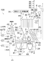
- the schematic block diagram of the waste incinerator including the incinerator which performs the method of this invention.
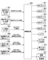
- Functional block diagram of waste incineration equipment The flowchart which shows the process which determines the supply amount of ammonium sulfate.
- the schematic block diagram of the waste incineration facility which concerns on another embodiment.
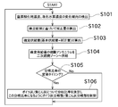
- the flowchart which shows the supply amount of ammonium sulfate, the presence or absence of supply of sulfuric acid / ammonia, and the process which determines the supply amount.
- FIG. 1 is a schematic configuration diagram of a waste incineration facility 100 including an incinerator 1 according to an embodiment of the present invention.
- upstream and downstream mean upstream and downstream in the direction in which waste, combustion gas, combustion gas, exhaust gas, etc. flow.
- the waste incinerator 100 includes an incinerator (waste incinerator) 1, a boiler 30, and a steam turbine power generation facility 35.
- the incinerator 1 incinerates the supplied waste. The detailed configuration of the incinerator 1 will be described later.
- the boiler 30 uses the heat generated by the combustion of waste to generate steam.
- the boiler 30 is a large number of heat transfer tubes 31 (specifically, a water tube 31a and a superheater tube 31b) provided on the flow path wall, and exchanges heat between high-temperature combustion gas generated in the furnace and water. Generates steam (superheated steam).
- the steam generated by the water pipe 31a and the superheater pipe 31b is supplied to the steam turbine power generation facility 35.
- the steam turbine power generation facility 35 includes a turbine and a power generation device (not shown).
- the turbine is rotationally driven by steam supplied from the water pipe 31a and the superheater pipe 31b.
- the power generation device uses the rotational driving force of the turbine to generate electricity.
- the incinerator 1 is provided with a dust supply device 40 for supplying waste into the furnace.
- the dust supply device 40 includes a waste input hopper 41 and a dust supply device main body 42.
- the waste input hopper 41 is a portion where waste is input from outside the furnace.
- the dust supply device main body 42 is located at the bottom of the waste input hopper 41 and is configured to be movable in the horizontal direction.
- the dust supply device main body 42 supplies the waste charged into the waste input hopper 41 to the downstream side.
- the moving speed of the dust supply device main body 42, the number of moving times per unit time, the moving amount (stroke), and the position of the stroke end (moving range) are controlled by the control device 90 shown in FIG.
- the dust supply device may be of a type that moves at a slight angle with respect to the horizontal direction.
- the waste supplied into the furnace by the dust supply device 40 is supplied to the combustion chamber 2.
- the combustion chamber 2 includes a primary combustion zone 10 and a secondary combustion zone 14.
- the primary combustion zone 10 is a space for primary combustion.
- the primary combustion is to react the input waste with a gas for primary combustion and burn it.
- the primary combustion gas is a gas containing oxygen supplied for primary combustion.
- the primary combustion gas includes primary air, circulating exhaust gas, and a mixed gas thereof.
- the primary air is air taken in from the outside and is not used for combustion or the like (that is, excluding circulating exhaust gas). Therefore, the primary air also includes a gas obtained by heating the air taken in from the outside. Further, the primary combustion generates a primary combustion gas (flue gas after premium flue gastion) containing an unburned gas such as CO.
- the primary combustion zone 10 is composed of a drying unit 11, a combustion unit 12, and a post-combustion unit 13.
- the waste is supplied by the transport unit 20 in the order of the drying unit 11, the combustion unit 12, and the post-combustion unit 13.
- the transport unit 20 is composed of a dry grate 21 provided in the drying unit 11, a combustion grate 22 provided in the combustion unit 12, and a post-combustion grate 23 provided in the post-combustion unit 13. There is. Therefore, the transport unit 20 is composed of a plurality of stages of grate. Each grate is provided on the bottom surface of each part, and waste is placed on it.
- the grate is composed of a movable grate and a fixed grate arranged side by side in the waste transport direction, and the movable grate intermittently moves forward and backward to transport waste to the downstream side. At the same time, the waste can be agitated.
- the operation of the grate is controlled by the control device 90.
- a gap having a size that allows gas to pass through is formed in the grate.
- the drying unit 11 is a portion for drying the waste supplied to the incinerator 1.
- the waste of the drying unit 11 is dried by the primary air supplied from under the drying grate 21 and the radiant heat of combustion in the adjacent combustion unit 12. At that time, thermal decomposition gas is generated from the waste of the drying portion 11 by thermal decomposition. Further, the waste of the drying unit 11 is conveyed toward the combustion unit 12 by the drying grate 21.
- the combustion unit 12 is a portion that mainly burns the waste dried in the drying unit 11.
- the waste mainly causes flame combustion to generate a flame.
- the waste in the combustion unit 12, the ash generated by combustion, and the unburned material that cannot be completely burned are conveyed toward the post-combustion unit 13 by the combustion grate 22. Further, the primary combustion gas and the flame generated in the combustion unit 12 pass through the throttle unit 17 and flow toward the post-combustion unit 13.
- the combustion grate 22 is provided at the same height as the dry grate 21, but may be provided at a position lower than the dry grate 21.
- the post-combustion unit 13 is a portion that burns the waste (unburned material) that could not be completely burned by the combustion unit 12.
- the radiant heat of the primary combustion gas and the primary air promote the combustion of the unburned material that could not be completely burned in the combustion unit 12.
- most of the unburned material becomes ash, and the unburned material decreases.
- the ash generated in the post-combustion unit 13 is conveyed toward the chute 24 by the post-combustion grate 23 provided on the bottom surface of the post-combustion unit 13.
- the ash conveyed to the chute 24 is discharged to the outside of the waste incineration facility 100.
- the rear combustion grate 23 of the present embodiment is provided at a position lower than the combustion grate 22, it may be provided at the same height as the combustion grate 22.
- each wall surface or the like is configured according to the reaction that occurs.
- flame combustion occurs in the combustion unit 12
- a structure having a higher refractory level than the drying unit 11 is adopted.
- the input waste is dried, burned, and post-combusted.
- the incinerator 1 of the present embodiment since each constituent stage is clearly separated, the above three processes are performed step by step.
- the present invention can be applied to incinerators having various configurations.
- the present invention is also applicable to incinerators in which each constituent stage is not clearly divided.
- the present invention is also applicable to an incinerator in which at least one of a drying stage and a post-combustion stage does not exist.
- the present invention can also be applied to an incinerator not provided with a grate, for example, a fluidized bed incinerator or a fixed bed incinerator.
- the secondary combustion zone 14 is a space for secondary combustion.
- the secondary combustion is to react the unburned gas contained in the primary combustion gas with the secondary combustion gas and burn it.
- the secondary combustion gas is a gas containing oxygen supplied for secondary combustion.
- the secondary combustion gas includes secondary air, circulating exhaust gas, and a mixed gas thereof. Secondary air is air taken in from the outside and is not used for combustion or the like (that is, excluding circulating exhaust gas). Combustion completeness can be promoted by performing secondary combustion.
- the secondary combustion zone 14 extends upward from the drying portion 11, the combustion portion 12, and the post-combustion portion 13, and the secondary air is supplied in the middle thereof. As a result, the primary combustion gas is mixed and agitated with the secondary air, and the unburned gas contained in the primary combustion gas is burned in the secondary combustion zone 14.
- Recirculated boiler ash (boiler ash) is supplied to the secondary combustion zone 14 by the boiler ash supply unit 46.
- the boiler ash is ash discharged or recovered by the boiler 30, for example, ash deposited on the bottom of the boiler 30 or ash collected by a filter provided on the boiler 30. Further, among the boiler ash, the one to be recirculated may be particularly referred to as recirculated boiler ash.
- the secondary combustion zone 14 is further supplied with recirculated dust collection ash (dust collection ash) by the dust collection ash supply unit 48.
- the dust collector ash is ash discharged or recovered by the dust collector 6, for example, ash collected by a filter provided in the dust collector 6. Further, among the dust collected ash, the one to be recirculated may be particularly referred to as recirculated dust collected ash.
- the boiler ash of the boiler 30 is collected by the boiler ash branching portion 45, and the dust collecting ash of the dust collector 6 is collected by the dust collecting ash branching portion 47.
- the boiler ash branch 45 and the dust collection ash branch 47 convey, for example, the accumulated or collected boiler ash or dust collection ash by using, for example, an air flow, a conveyor, or a natural drop. to recover.
- a supply path for supplying boiler ash or dust collecting ash is formed between the boiler ash branching section 45 and the boiler ash supply section 46, and between the dust collecting ash branching section 47 and the dust collecting ash supply section 48. In this supply route, for example, the boiler ash or dust collecting ash is supplied to the boiler ash supply unit 46 or the dust collecting ash supply unit 48 by any of the above-mentioned transport methods.
- a cleaning device may be further provided in the supply path of the boiler ash and the dust collecting ash.
- the cleaning device removes water-soluble salts contained in the boiler ash and the dust collection ash by cleaning at least a part of the boiler ash and the dust collection ash supplied to the secondary combustion zone 14 with water. It is a device that performs salt treatment).
- the cleaning device is not limited to simple water, and cleaning water containing a predetermined chemical may be used. As this chemical, for example, it is preferable to use a chemical for removing a salt that easily melts (for example, a salt having a low melting point) after being supplied to the secondary combustion zone 14.
- the boiler ash and the dust collecting ash are not limited to the secondary combustion zone 14, but are supplied to somewhere in the region from the secondary combustion zone 14 to the heat transfer tube 31 (including the secondary combustion zone 14 and the heat transfer tube 31). Just do it.
- boiler ash and dust collecting ash are recirculated, but some boiler ash and dust collecting ash are recirculated, and the remaining boiler ash and dust collecting ash are shown in the figure. It is collected in a collection container. Further, only one of the boiler ash and the dust collecting ash may be recirculated.
- Ammonium sulfate is further supplied to the secondary combustion zone 14 by the ammonium sulfate supply unit 57.
- the ammonium sulfate supply unit 57 is connected to a storage unit that stores ammonium sulfate via a supply path for supplying ammonium sulfate toward the secondary combustion zone 14.
- Ammonium sulfate has a function of reducing nitrogen oxide emissions (denitration) and a function of reducing corrosion of the heat transfer tube 31 of the boiler 30.
- the boiler ash and the dust collecting ash have a function of exerting a function of reducing corrosion of the heat transfer tube 31 of the boiler 30 with a smaller amount of ammonium sulfate supplied.
- Ammonium sulfate is thermally decomposed by being supplied to the high temperature secondary combustion zone 14, and ammonia, sulfur oxides (for example, sulfur dioxide), nitrogen, water, and the like are produced. Since this ammonia acts as a reducing agent, nitrogen oxides can be reduced to nitrogen. This method is called non-catalytic denitration because denitration is performed without using a denitration catalyst.
- Corrosion of the heat transfer tube 31 is caused by the combustion gas generated in the incinerator 1. Specifically, since waste contains various metals, chlorine compounds, sulfur compounds, and the like, these react to generate various types of salts. Since this mixture of various kinds of salts corrodes the heat transfer tube 31, it is hereinafter referred to as a corrosive substance. Since the corrosive substance exceeds the melting point in the high temperature secondary combustion zone 14, it becomes a molten state and flows downstream together with the combustion gas generated by the combustion in the incinerator 1.
- ammonium sulfate has the effect of reducing corrosion, but for example, the amount of salt having a low melting point reaching the heat transfer tube 31 increases, or the surface temperature of the heat transfer tube 31 rises to generate molten salt. If it becomes easier to do so, it is necessary to increase the supply amount of ammonium sulfate in order to further exert the effect of reducing corrosion. However, increasing the supply of ammonium sulphate increases costs.
- a part of the recirculated boiler ash and the recirculated dust collection ash containing a large amount of sulfur oxide salts and other substances having a high melting point due to ammonium sulfate are recirculated to the secondary combustion zone 14.
- Supply As a result, the proportion of salts having a low melting point reaching the heat transfer tube 31 is relatively reduced, so that it is possible to make it difficult to form a molten salt with a smaller amount of ammonium sulfate supplied and to exert the same corrosion reducing effect. To do.
- the downstream end of the secondary combustion zone 14 and the upstream end of the region where the heat transfer tube 31 is arranged are connected. Therefore, in order to increase the salts of sulfur oxides before the corrosive substance reaches the heat transfer tube 31, ammonium sulfate is relatively upstream of the secondary combustion zone 14 (for example, from the center of the combustion gas flow direction). It is preferable to supply the flame to the upstream side or the region where the flame generated in the primary combustion zone 10 reaches the secondary combustion zone 14.
- the recirculated boiler ash and the recirculated dust ash do not require a pre-reaction like ammonium sulfate, so the function exhibited does not change no matter where they are supplied in the secondary combustion zone 14.
- secondary combustion is performed if it is upstream from the target location of the corrosion reduction effect (that is, at least a part of the heat transfer tube 31). It may be on the downstream side of the zone 14.
- ammonium sulfate may be supplied in any form of powder, granules, and aqueous solution. Which form to supply is determined in consideration of reaction rate, handleability, amount of money, weight and the like. For example, regarding the reaction rate, the aqueous solution, the powder, and the granules are in the order of earliest. Since the aqueous solution is ionized, the reaction occurs in a short time. On the other hand, since the surface area of the granules is relatively small as compared with the powder, the time until the reaction occurs becomes long. On the other hand, the recirculated boiler ash and the recirculated dust ash do not need to be pretreated and may be supplied as the collected powder.
- the high-temperature secondary combustion gas discharged in the secondary combustion is discharged as exhaust gas after passing through the boiler 30 as described above.
- the exhaust gas discharged from the incinerator 1 is purified by a filtration type dust collector 6 arranged on the downstream side.
- a chemical for reducing the concentration of gaseous harmful substances (hydrogen chloride, sulfur oxides, dioxins, etc.) contained in the exhaust gas. Is thrown in.
- the waste incineration facility 100 includes a chemical tank 7 and a valve 8.
- Various chemicals for reducing these harmful substances are stored in the chemical tank 7.
- the valve 8 has a mechanism for adjusting the amount of the drug supplied to the flue.
- the control device 90 determines the type and supply amount of the chemical to be used based on the detection result of the properties of the exhaust gas, the target value, and the like, and controls to change the opening degree of the valve 8 accordingly.
- the boiler ash collected in the boiler ash branch portion 45 is divided into discharged boiler ash discharged to the outside of the furnace and recirculated boiler ash.
- the dust collected ash collected in the dust collecting ash branching portion 47 is divided into discharged dust collecting ash discharged to the outside of the furnace and recirculated dust collecting ash.
- the discharged boiler ash and the discharged dust ash are discharged to the outside of the furnace.
- the recirculated boiler ash and the recirculated dust collection ash are supplied to the secondary combustion zone 14 and the like.
- the boiler ash branching portion 45 and the dust collecting ash branching portion 47 are controlled by the control device 90 as shown in FIG.
- the ratio for discharge and recirculation is based on the signal received from the control device 90. Is configured to change.
- the structure that constitutes the ratio is arbitrary, and for example, a valve whose opening degree can be adjusted may be used, or a structure that moves a partition plate that separates a path for discharge and recirculation may be used. The process of determining the ratio between discharge and recirculation will be described later.
- the gas supply device 50 is a device that supplies gas (primary combustion gas, secondary combustion gas) into the combustion chamber 2.
- the gas supply device 50 of the present embodiment includes a primary air supply unit 51, a secondary air supply unit 52, and an exhaust gas supply unit 53.
- Each supply unit is composed of a blower for attracting or sending out gas.
- the primary air supply unit 51 supplies the primary air to the combustion chamber 2 via the primary supply path 71.
- the primary supply path 71 is provided below the dry stage air box 25 provided below the dry grate 21, the combustion stage air box 26 provided below the combustion grate 22, and the post-combustion grate 23. This is a route for supplying primary air to each of the post-combustion stage air boxes 27.
- the primary supply path 71 includes a first damper 81 that adjusts the supply amount of the primary air supplied to the drying stage air box 25, and a second damper 82 that adjusts the supply amount of the primary air supplied to the combustion stage air box 26.
- a third damper 83 for adjusting the supply amount of the primary air supplied to the post-combustion stage air box 27 is provided. As shown in FIG. 2, the first damper 81, the second damper 82, and the third damper 83 are controlled by the control device 90.
- a heater may be provided in the primary supply path 71 so that the temperature of the primary air supplied to the combustion chamber 2 can be adjusted.
- the primary combustion gas also includes the circulating exhaust gas and the mixed gas, they may be supplied to the combustion chamber 2.
- the primary combustion gas is supplied to the primary combustion zone 10 from below, but may be supplied from the side of the primary combustion zone 10 or the like. Further, the gas for primary combustion may be supplied to the upstream side of the primary combustion zone 10 if it is used for primary combustion.
- the secondary air supply unit 52 supplies the secondary air to the combustion chamber 2 via the secondary supply path 72.
- the secondary air supply unit 52 supplies secondary air to the air gas holding space 16 of the incinerator 1 from the upper part (ceiling portion), and the combustion gas changes direction by the throttle unit 17.
- the secondary air By supplying the secondary air (near the throttle portion 17), the secondary air is supplied to the secondary combustion zone 14.
- the secondary supply path 72 is provided with a fifth damper 85 that adjusts the supply amount of the secondary air to be supplied in the vicinity of the air gas holding space 16 and the throttle portion 17. As shown in FIG. 2, the fifth damper 85 is controlled by the control device 90.
- the exhaust gas supply unit 53 supplies (recirculates) the exhaust gas discharged from the waste incineration facility 100 into the furnace via the circulating exhaust gas supply path 73.
- a part of the exhaust gas discharged from the waste incinerator 100 and purified by the dust collector 6 is supplied to the incinerator 1 from both side surfaces (front side and back side of the paper surface) of the combustion unit 12 by the exhaust gas supply unit 53. Will be done.
- the position where the exhaust gas is supplied is not particularly limited.
- the exhaust gas may be supplied from above (ceiling portion) of the incinerator 1 or may be supplied from only one side surface.
- the circulating exhaust gas supply path 73 is provided with a fourth damper 84 for adjusting the supply amount of the circulating exhaust gas. As shown in FIG. 2, the fourth damper 84 is controlled by the control device 90.
- the incinerator 1 is provided with a plurality of sensors for grasping the combustion state and the like.
- the incinerator 1 includes an incinerator gas temperature sensor 91, an incinerator outlet gas temperature sensor 92, a CO concentration sensor 93, a nitrogen oxide concentration sensor 94, and a hydrogen chloride concentration sensor 95.
- a sulfur oxide concentration sensor 96 is provided.
- the gas temperature sensor 91 in the incinerator is arranged in the incinerator 1 (for example, downstream of the air gas holding space 16 and upstream of the post-combustion unit 13), detects the gas temperature in the incinerator, and controls the control device 90. Output to.
- the incinerator outlet gas temperature sensor 92 is arranged near the incinerator 1 outlet (for example, downstream of the secondary combustion zone 14 and upstream of the boiler 30), detects the incinerator outlet gas temperature, and sends it to the control device 90. Output.
- the CO concentration sensor 93, the nitrogen oxide concentration sensor 94, the hydrogen chloride concentration sensor 95, and the sulfur oxide concentration sensor 96 are all arranged downstream of the dust collector 6, respectively. The hydrogen chloride concentration and the sulfur oxide concentration are detected and output to the control device 90.
- the control device 90 is composed of a CPU, RAM, ROM, etc., performs various calculations, and controls the entire incinerator 1. Specifically, the control device 90 controls the incinerator 1 based on the data acquired by the above sensor, the specifications of the incinerator 1, target values of various data, other preset parameters, and the like. For example, the control device 90 adjusts the supply amount of gas supplied to each part by controlling the first damper 81 to the fifth damper 85. Further, although not shown in FIG. 2, the control device 90 adjusts the waste transport speed by controlling the dry grate 21, the combustion grate 22, and the post-combustion grate 23. Further, the control device 90 controls the valve 8 to adjust the type and supply amount of the drug for removing harmful substances. Further, the control device 90 adjusts the supply amount of ammonium sulfate by controlling the ammonium sulfate supply unit 57.
- FIG. 3 is a flowchart showing a process of determining the supply amount of ammonium sulfate.
- control device 90 detects the tendency of change in the nitrogen oxide concentration and the hydrogen chloride concentration, respectively, based on the detection results of the nitrogen oxide concentration sensor 94 and the hydrogen chloride concentration sensor 95 (S101).
- the change tendency is a value indicating how large the detected value is as compared with the steady value.
- the control device 90 calculates the correction amount of the supply of ammonium sulfate based on the change tendency of the hydrogen chloride concentration (S102), and calculates the fixed supply amount by adding the correction amount to the basic supply amount of ammonium sulfate (S102). S103).
- ammonium sulfate has a function of reducing the amount of nitrogen oxide emissions, and therefore, based on the amount of nitrogen oxides to be reduced, etc. (for example, the detection result and target value of the nitrogen oxide concentration sensor 94).
- the basic supply amount which is the amount of ammonium sulfate to be supplied, is determined.
- the basic supply amount may be determined according to the properties of the waste charged into the incinerator 1 in addition to the detected value of the nitrogen oxide concentration sensor 94. Alternatively, the basic supply amount may be determined without considering the detection result of the nitrogen oxide concentration sensor 94. In this case, the basic supply amount may be a constant value.
- the value obtained by correcting this basic supply amount according to the correction amount is the fixed supply amount, and the ammonium sulfate of this fixed supply amount is supplied to the secondary combustion zone 14. Further, in the present embodiment, the correction amount is calculated based on the change tendency of the hydrogen chloride concentration.
- the concentration of hydrogen chloride in the exhaust gas passing through the flue is affected by a time delay and reduction by chemicals. However, there is a correlation with the hydrogen chloride concentration in the combustion gas passing around the secondary combustion zone 14 and the heat transfer tube 31 and the like.
- the concentration of hydrogen chloride in the combustion gas is high, the proportion of chlorine salts in the corrosive substance is high, so that the melting point of the corrosive substance is low and the corrosive substance in the molten state adheres to the heat transfer tube 31. It will be easier. Therefore, it is preferable to supply a large amount of ammonium sulfate (sulfur oxide generated thereby) to the secondary combustion zone 14 as the concentration of hydrogen chloride in the combustion gas is higher. Therefore, as the hydrogen chloride concentration increases, the correction amount calculated by the control device 90 increases.
- the supply amount of recirculation boiler ash / recirculation dust collection ash or the ratio for recirculation is also effective in reducing corrosion, so this supply amount is further taken into consideration (that is, recirculation boiler ash / recirculation dust collection ash).
- the correction amount may be calculated so that the correction amount becomes smaller as the supply amount or ratio of the above increases.
- control device 90 controls the ammonium sulfate supply unit 57 to supply the determined supply amount of ammonium sulfate calculated in step S103 to the secondary combustion zone 14 (S104).
- the control device 90 determines whether or not it is time to change the discharge amount of boiler ash / dust ash and the ratio for recirculation (hereinafter, branching ratio) (S105), and if it is the timing to change.
- the branching ratio of the boiler ash / dust collecting ash is determined, and at least one of the boiler ash branching portion 45 and the dust collecting ash branching portion 47 is controlled so as to have this branching ratio (S106). Since it takes a long time from changing the branching ratio until the actual effect occurs, it is preferable to change the branching ratio in a cycle longer than the supply amount of ammonium sulfate. Therefore, the process of changing the branch ratio is performed only when the change timing arrives.
- the branching ratio is individually determined in advance for each facility's required performance and characteristics, such as the properties of the waste to be incinerated, the composition of the exhaust gas treatment system, the ability to reduce the concentration of harmful substances in the exhaust gas treatment system, and the steam temperature of the boiler 30. It is determined by the calculation formula set in, and is changed according to the situation of facility operation. In addition, the properties of waste and the state of facility operation can be determined by using the tendency of the detection results of, for example, the gas temperature sensor 91 in the incinerator to the sulfur oxide concentration sensor 96 over a long period of time. Further, as described above, the recirculated boiler ash / recirculated dust ash has a role of assisting the effect of reducing corrosion by ammonium sulfate.
- the branching ratio is determined so as to increase the recirculation ratio. As a result, it is possible to exert a sufficient effect of reducing the corrosion of the boiler without increasing the supply amount of ammonium sulfate.
- the correction amount is calculated based only on the change tendency of the hydrogen chloride concentration, but in addition to this, the correction amount may be further calculated based on the supply amount of the drug for removing harmful substances. .. This is because the hydrogen chloride concentration detected by the hydrogen chloride concentration sensor 95 decreases as the supply amount of this drug increases. Further, in addition to or in place of the supply amount of the drug, the correction amount may be further calculated based on the change tendency of the sulfur oxide concentration detected by the sulfur oxide concentration sensor 96. This is because as the concentration of sulfur oxides in the exhaust gas increases, the proportion of sulfur oxide salts in the corrosive substance tends to increase. Therefore, as the sulfur oxide concentration in the exhaust gas increases, the correction amount calculated by the control device 90 decreases.
- the correction amount is calculated based on the change tendency of the hydrogen chloride concentration and the change tendency of the sulfur oxide concentration. For example, the change tendency of the hydrogen chloride concentration and the change tendency of the sulfur oxide concentration are compared, and the correction amount is calculated according to the concentration having the larger degree of the change tendency.
- FIG. 4 is a schematic configuration diagram of the waste incineration facility 100 according to another embodiment.
- FIG. 5 is a flowchart showing a process of determining the supply amount of ammonium sulfate, the presence / absence of supply of sulfuric acid / ammonia, and the supply amount.
- the incinerator 1 of the present embodiment further includes a sulfuric acid supply device 58 and an ammonia water supply device 59.
- the sulfuric acid supply device 58 and the ammonia water supply device 59 are arranged in the vicinity of the ammonium sulfate supply unit 57, and supply sulfuric acid and ammonia water to the secondary combustion zone 14, respectively.
- the sulfuric acid supply device 58 includes a storage unit for storing sulfuric acid and a supply path for supplying sulfuric acid.
- the ammonia water supply device 59 includes a storage unit for storing ammonia water and a supply path for supplying ammonia water.
- ammonium sulfate has both functions of reducing nitrogen oxide emissions and reducing corrosion of the boiler 30, but if the supply amount is increased to reduce nitrogen oxide emissions, for example, sulfur oxides will be excessive. It will be supplied (the reverse pattern can occur).
- sulfuric acid and aqueous ammonia are supplied in consideration of them.
- control device 90 has a nitrogen oxide concentration, a hydrogen chloride concentration, and sulfur, respectively, based on the detection results of the nitrogen oxide concentration sensor 94, the hydrogen chloride concentration sensor 95, and the sulfur oxide concentration sensor 96, respectively.
- the tendency of change in oxide concentration is detected (S201).
- the control device 90 is based on the changing tendency of the hydrogen chloride concentration (or the changing tendency of the sulfur oxide concentration, and the supply amount or branching of the recirculation boiler ash / recirculation dust collection ash.
- the corrected amount and the fixed supply amount of ammonium sulfate are calculated (S202, S203) by further using the ratio.
- the control device 90 determines the presence / absence and supply amount of sulfuric acid and ammonia water based on the detection result in step S201 (S204). That is, the amount of ammonia to be supplied for reducing the emission of nitrogen oxides can be calculated from the tendency of change in nitrogen oxide concentration and other data. Then, the amount of sulfur oxide to be supplied for reducing the corrosion of the boiler 30 can be calculated based on the changing tendency of the hydrogen chloride concentration (or further using the changing tendency of the sulfur oxide concentration). If the amount of ammonia to be supplied and the amount of sulfur oxides are well-balanced and only ammonium sulfate is supplied without a large excess or deficiency, only ammonium sulfate is supplied.
- the amount of sulfur oxide to be supplied is relatively large compared to the amount of ammonia
- sulfuric acid is supplied in addition to ammonium sulfate
- ammonium sulfate is supplied.
- ammonia water is supplied.
- the supply amount of sulfuric acid / ammonia water is a value obtained by subtracting the amount of sulfur oxide / ammonia supplied by ammonium sulfate from the amount of sulfur oxide / ammonia to be supplied.
- the amount of ammonia water supplied is determined based on the tendency of changes in the nitrogen oxide concentration and the amount of ammonium sulfate supplied.
- the amount of ammonium sulfate supplied is determined based on the tendency of change in hydrogen chloride concentration. Therefore, the supply amount of ammonia water is further determined based on the tendency of change in hydrogen chloride concentration. It can also be understood that the supply amounts of sulfuric acid and ammonia water are determined based on the correction amount of ammonium sulfate.
- control device 90 supplies the fixed supply amount of ammonium sulfate calculated in step S203 to the secondary combustion zone 14 in the form of an aqueous solution, and supplies the supply amount of sulfuric acid or ammonia water determined in step S204 to the secondary combustion zone. Supply to 14 (S205).
- the control device 90 determines whether or not it is the timing to change the branching ratio (S206), as in steps S105 and S106, and if it is the timing to change, the branching ratio is determined for the boiler ash / dust collecting ash. It is determined, and at least one of the boiler ash branching portion 45 and the dust collecting ash branching portion 47 is controlled so as to have this branching ratio (S207).
- the waste incineration facility 100 of the present embodiment includes both a sulfuric acid supply device 58 and an ammonia water supply device 59. Instead, the waste incineration facility 100 may be configured to include only one of the sulfuric acid supply device 58 and the ammonia water supply device 59.
- the boiler ash branching section 45, the dust collecting ash branching section 47, the ammonium sulfate supply section 57, the sulfuric acid supply device 58, and the ammonia water supply device 59 are arranged side by side. If each substance is supplied to a required area, each substance may be arranged at a distant position.
- the process of changing the branching ratio of the boiler ash / dust collecting ash is performed, but the branching ratio may always be constant (a configuration having no function of changing the branching ratio).
- the branching ratio may always be constant (a configuration having no function of changing the branching ratio).
- the denitration and corrosion reduction method of the waste incineration facility 100 of the above embodiment includes a primary combustion zone 10 for performing primary combustion and a primary combustion gas including unburned gas generated in the primary combustion.
- a combustion chamber 2 having a secondary combustion zone 14 for performing secondary combustion, a boiler 30 having a heat transfer tube 31 for recovering heat generated in the combustion chamber 2, and exhaust gas generated in the combustion chamber 2 This is performed on the waste incineration facility 100 including the dust collector 6 for purifying.
- the denitration and corrosion reduction method of the waste incineration facility 100 includes an ammonium sulfate supply step and an ash supply step. In the ammonium sulfate supply step, ammonium sulfate is supplied to the secondary combustion zone 14.
- At least one of the boiler ash discharged from the boiler 30 and the dust collecting ash discharged from the dust collector 6 is transferred from the secondary combustion zone 14 to the heat transfer tube 31 (secondary combustion zone 14 and transfer). Supply somewhere (including the heat tube 31).
- ammonium sulfate is thermally decomposed to generate ammonia, and this ammonia can reduce nitrogen oxides.
- sulfur oxides are generated from ammonium sulfate, the proportion of sulfur oxide salts in the corrosive substance, which is a mixture of various types of salts in which a metal and an acid group are bonded, is in the vicinity of the heat transfer tube 31 of the boiler 30. Increase (on the contrary, decrease the proportion of chlorine salts).
- the melting point of the corrosive substance rises, the corrosive substance is less likely to exist as a molten salt, so that the progress of corrosion of the heat transfer tube 31 of the boiler 30 can be reduced.
- Boiler ash and dust collection ash contain a large amount of sulfur oxide salts due to the supplied ammonium sulfate, and as a result, the proportion of sulfur oxide salts increases in the vicinity of the heat transfer tube 31, resulting in corrosion of the heat transfer tube 31. Progress can be reduced. Therefore, the progress of corrosion of the heat transfer tube 31 can be reduced without increasing the supply amount of ammonium sulfate.
- the ash supply step before supplying at least one of the boiler ash and the dust collection ash (of these boiler ash / dust collection ash). Wash and remove the water-soluble salts contained in it.
- the denitration and corrosion reduction method of the waste incineration equipment 100 of the above embodiment includes a detection step and a correction step. It includes a detection step, a correction step, and a supply step.
- the detection step the tendency of change in the concentration of hydrogen chloride contained in the exhaust gas discharged from the combustion chamber 2 and passing through the heat transfer tube 31 and the dust collector 6 is detected.
- the correction step the correction amount of ammonium sulfate supplied for denitration and reduction of corrosion of the heat transfer tube is calculated based on the change tendency of the hydrogen chloride concentration detected in the detection step.
- the supply step a fixed supply amount of ammonium sulfate obtained by correcting the basic supply amount of ammonium sulfate with a correction amount is supplied to the secondary combustion zone 14.
- the hydrogen chloride concentration sensor 95 which is a detection device, is less likely to be contaminated because the hydrogen chloride concentration in the exhaust gas that has passed through the dust collector 6 is measured, the hydrogen chloride concentration can be stably detected for a long period of time. ..
- a fixed supply amount of ammonium sulfate is supplied to the secondary combustion zone 14 in the form of an aqueous solution, and hydrogen chloride detected in the detection step is supplied.
- a supply amount of sulfuric acid determined based on the tendency of change in concentration is supplied to the secondary combustion zone 14.
- a fixed supply amount of ammonium sulfate is supplied to the secondary combustion zone 14 in the form of an aqueous solution, and hydrogen chloride detected in the detection step is supplied.
- a supply amount of aqueous ammonia determined based on the tendency of change in concentration is supplied to the secondary combustion zone 14.
- the denitration effect can be enhanced without increasing the amount of sulfur oxides generated. Further, by supplying ammonium sulfate and ammonia as an aqueous solution, it is possible to shorten the time until it contributes to denitration and reduction of corrosion.
Landscapes
- Engineering & Computer Science (AREA)
- Mechanical Engineering (AREA)
- General Engineering & Computer Science (AREA)
- Incineration Of Waste (AREA)
- Chemical & Material Sciences (AREA)
- Combustion & Propulsion (AREA)
- Chimneys And Flues (AREA)
Abstract
廃棄物焼却設備(100)の脱硝及び腐食低減方法は、一次燃焼ゾーン(10)、及び、二次燃焼ゾーン(14)を有する燃焼室(2)と、ボイラ(30)と、集じん器(6)と、を備える廃棄物焼却設備(100)に対して行われる。この方法は、硫酸アンモニウム供給工程と、灰供給工程と、を含む。硫酸アンモニウム供給工程では、硫酸アンモニウムを二次燃焼ゾーン(14)へ供給する。灰供給工程では、ボイラ灰及び集じん灰の少なくとも一方を、二次燃焼ゾーン(14)からボイラ(30)の伝熱管(31)までの領域の何処かに供給する。
Description
本発明は、主として、廃棄物焼却炉及びボイラを備える廃棄物焼却設備に対して、窒素酸化物の排出量を低減させつつ、ボイラの伝熱管に生じる腐食を低減する方法に関する。
従来から、廃棄物焼却炉で発生した排ガスに含まれる窒素酸化物を低減するために、尿素等の薬剤を炉内に供給する方法が用いられている。また、廃棄物焼却炉の熱を回収するボイラの伝熱管の腐食を低減するために、硫黄化合物等の腐食低減剤を炉内に供給する方法が用いられている。
特許文献1には、窒素酸化物の排出量を低減するための薬剤として、尿素水溶液又はアンモニア水溶液を用いることが記載されている。
特許文献2には、廃棄物焼却において生成・回収される飛灰(集じん灰)中のダイオキシン類を分解させるために、当該飛灰の一部を焼却炉の火炎上部に供給(再投入)する技術が記載されている。
特許文献3には、ボイラの伝熱管の腐食を低減するために、硫酸アンモニウム等の硫黄含有化合物を用いることが記載されている。特許文献3には、硫酸アンモニウムを用いることで、更に、窒素酸化物の排出量を低減できることが記載されている。また、特許文献3には、燃焼室を通過してボイラの過熱器管(伝熱管)へ向かう排ガスに含まれるNaClガス濃度又はKClガス濃度を測定し、濃度の測定結果に基づいて硫黄含有化合物の供給量を調整することが記載されている。
しかし、特許文献1及び2の技術は窒素酸化物の排出量を低減することしかできず、ボイラの伝熱管の腐食を低減することはできない。
また、特許文献3の技術は、窒素酸化物の排出量低減とボイラの伝熱管の腐食低減の両方を実現できる。しかし、特許文献3の方法では、バグフィルタ等の集じん器で浄化される前の排ガスに含まれるNaClガス濃度等を測定するため、測定装置が汚染され易くなり、長期間にわたって安定して測定を行うことが困難となる。更に、特許文献3では、NaClガス濃度又はKClガス濃度を測定することは記載されているが、他の塩素化合物を計測することについては記載されていない。
本発明は以上の事情に鑑みてされたものであり、その主要な目的は、廃棄物焼却炉及びボイラを備える廃棄物焼却設備に対して、薬剤の供給量を過大にすることなく、長期間にわたって安定して、窒素酸化物の排出量を低減させつつ(脱硝反応を生じさせつつ)、ボイラの伝熱管に生じる腐食を低減する方法を提供することにある。
本発明の解決しようとする課題は以上の如くであり、次にこの課題を解決するための手段とその効果を説明する。
本発明の観点によれば、以下の廃棄物焼却設備の脱硝及び腐食低減方法が提供される。即ち、この方法は、一次燃焼を行うための一次燃焼ゾーン、及び、一次燃焼で発生した未燃焼ガスを含む一次燃焼ガスを燃焼させる二次燃焼を行うための二次燃焼ゾーンを有する燃焼室と、当該燃焼室で発生した熱を回収する伝熱管を有するボイラと、前記燃焼室で発生した排ガスを浄化する集じん器と、を備える廃棄物焼却設備に対して行われる。この方法は、硫酸アンモニウム供給工程と、灰供給工程と、を含む。前記硫酸アンモニウム供給工程では、硫酸アンモニウムを前記二次燃焼ゾーンへ供給する。前記灰供給工程では、前記ボイラから排出されるボイラ灰及び前記集じん器から排出される集じん灰の少なくとも一方を、前記二次燃焼ゾーンから前記伝熱管までの領域の何処かに供給する。
これにより、硫酸アンモニウムは熱分解することでアンモニアが発生するため、このアンモニアにより窒素酸化物を還元することができる。また、硫酸アンモニウムから硫黄酸化物が生じるため、ボイラの伝熱管の近傍において、金属と酸基が結合した様々な種類の塩類の混合物である腐食性物質内の硫黄酸化物の塩類の割合が多くなる(反対に、塩素の塩類の割合が少なくなる)。その結果、腐食性物質の融点が上昇するため、腐食性物質が溶融塩として存在しにくくなるので、ボイラの伝熱管の腐食の進行を低減できる。更に、灰供給工程を行うことで、ボイラ灰及び集じん灰の少なくとも一方が炉内に付加的に供給される。ボイラ灰や集じん灰には、供給された硫酸アンモニウムに起因する硫黄酸化物の塩類が多く含まれるため、伝熱管の近傍において硫黄酸化物の塩類の割合が多くなる結果、伝熱管の腐食の進行を低減できる。従って、硫酸アンモニウムの供給量を過大にすることなく、伝熱管の腐食の進行を低減できる。
本発明によれば、廃棄物焼却炉及びボイラを備える廃棄物焼却設備に対して、薬剤の供給量を過大にすることなく、長期間にわたって安定して、窒素酸化物の排出量を低減させつつ(脱硝反応を生じさせつつ)、ボイラの伝熱管に生じる腐食を低減する方法が実現できる。
<廃棄物焼却設備の全体構成>初めに、図1を参照して、本実施形態の焼却炉1を含む廃棄物焼却設備100について説明する。図1は、本発明の一実施形態の焼却炉1を含む廃棄物焼却設備100の概略構成図である。なお、以下の説明では、単に上流、下流と記載したときは、廃棄物、燃焼ガス、燃焼用気体、排ガス等が流れる方向の上流及び下流を意味するものとする。
図1に示すように、廃棄物焼却設備100は、焼却炉(廃棄物焼却炉)1と、ボイラ30と、蒸気タービン発電設備35と、を備える。焼却炉1は、供給された廃棄物を焼却する。なお、焼却炉1の詳細な構成は後述する。
ボイラ30は、廃棄物の燃焼によって発生した熱を利用して蒸気を生成する。ボイラ30は、流路壁に設けられた多数の伝熱管31(具体的には水管31a及び過熱器管31b)で、炉内で発生した高温の燃焼ガスと水との熱交換を行うことにより蒸気(過熱蒸気)を生成する。水管31a及び過熱器管31bで生成された蒸気は、蒸気タービン発電設備35へ供給される。
蒸気タービン発電設備35は、図略のタービン及び発電装置を含んで構成されている。タービンは、水管31a及び過熱器管31bから供給された蒸気によって回転駆動される。発電装置は、タービンの回転駆動力を用いて発電を行う。
<焼却炉の構成>焼却炉1は、廃棄物を炉内に供給するための給じん装置40を備える。給じん装置40は、廃棄物投入ホッパ41と、給じん装置本体42と、を備える。廃棄物投入ホッパ41は、炉外から廃棄物が投入される部分である。給じん装置本体42は、廃棄物投入ホッパ41の底部分に位置し、水平方向に移動可能に構成されている。給じん装置本体42は、廃棄物投入ホッパ41に投入された廃棄物を下流側に供給する。この給じん装置本体42の移動速度、単位時間あたりの移動回数、移動量(ストローク)、及びストローク端の位置(移動範囲)は、図2に示す制御装置90によって制御されている。なお、給じん装置は水平方向に対し多少の角度をもって移動する型式でもよい。
給じん装置40によって炉内に供給された廃棄物は、燃焼室2に供給される。燃焼室2は、一次燃焼ゾーン10と、二次燃焼ゾーン14と、を含んでいる。一次燃焼ゾーン10は、一次燃焼のための空間である。一次燃焼とは、投入された廃棄物を一次燃焼用気体(gas for primary combustion)と反応させて燃焼させることである。一次燃焼用気体とは、一次燃焼のために供給される酸素を含んだ気体である。一次燃焼用気体としては、一次空気、循環排ガス、それらの混合ガスが含まれる。一次空気とは、外部から取り込んだ空気であって、燃焼等に用いられていない(即ち、循環排ガスを除く)気体である。従って、一次空気には、外部から取り込んだ空気を加熱等した気体も含まれる。また、一次燃焼により、CO等の未燃焼ガスを含む一次燃焼ガス(flue gas after primary combustion)が発生する。
一次燃焼ゾーン10は、乾燥部11と、燃焼部12と、後燃焼部13と、から構成されている。廃棄物は、搬送部20によって、乾燥部11、燃焼部12、及び後燃焼部13の順に供給されていく。搬送部20は、乾燥部11に設けられた乾燥火格子21と、燃焼部12に設けられた燃焼火格子22と、後燃焼部13に設けられた後燃焼火格子23と、で構成されている。従って、搬送部20は複数段の火格子から構成されている。それぞれの火格子は、各部の底面に設けられており、廃棄物が載置される。火格子は、廃棄物搬送方向に並べて配置された可動火格子と固定火格子とから構成されており、可動火格子が間欠的に前進及び後進を行うことで、廃棄物を下流側へ搬送するとともに、廃棄物を攪拌することができる。なお、火格子の動作は、制御装置90によって制御されている。また、火格子には、気体が通過可能な大きさの隙間が形成されている。
乾燥部11は、焼却炉1に供給された廃棄物を乾燥させる部分である。乾燥部11の廃棄物は、乾燥火格子21の下から供給される一次空気及び隣接する燃焼部12における燃焼の輻射熱によって乾燥する。その際、熱分解によって乾燥部11の廃棄物から熱分解ガスが発生する。また、乾燥部11の廃棄物は、乾燥火格子21によって燃焼部12に向かって搬送される。
燃焼部12は、乾燥部11で乾燥した廃棄物を主に燃焼させる部分である。燃焼部12では、廃棄物が主に火炎燃焼を起こし火炎が発生する。燃焼部12における廃棄物及び燃焼により発生した灰及び燃焼しきれなかった未燃物は、燃焼火格子22によって後燃焼部13に向かって搬送される。また、燃焼部12で発生した一次燃焼ガス及び火炎は、絞り部17を通過して後燃焼部13に向かって流れる。なお、燃焼火格子22は、乾燥火格子21と同じ高さに設けられているが、乾燥火格子21よりも低い位置に設けられていてもよい。
後燃焼部13は、燃焼部12で燃焼しきれなかった廃棄物(未燃物)を燃焼させる部分である。後燃焼部13では、一次燃焼ガスの輻射熱と一次空気によって、燃焼部12で燃焼しきれなかった未燃物の燃焼が促進される。その結果、未燃物の殆どが灰となって、未燃物は減少する。なお、後燃焼部13で発生した灰は、後燃焼部13の底面に設けられた後燃焼火格子23によってシュート24に向かって搬送される。シュート24に搬送された灰は、廃棄物焼却設備100の外部に排出される。なお、本実施形態の後燃焼火格子23は、燃焼火格子22よりも低い位置に設けられているが、燃焼火格子22と同じ高さに設けられていてもよい。
上述したように、乾燥部11、燃焼部12、及び後燃焼部13では、生じる反応が異なるため、それぞれの壁面等は、生じる反応に応じた構成となっている。例えば、燃焼部12では火炎燃焼が生じるため、乾燥部11よりも耐火レベルが高い構造が採用されている。
以上で説明したように、本実施形態の焼却炉1の一次燃焼ゾーン10では、投入された廃棄物に対して、乾燥、燃焼、及び後燃焼が行われる。本実施形態の焼却炉1では、各構成段が明確に分かれているため、上記の3つの処理が段階的に行われる。なお、本発明は、様々な構成の焼却炉に適用可能である。例えば、本発明は、各構成段が明確に区分されていない焼却炉にも適用可能である。また、本発明は、乾燥段及び後燃焼段の少なくとも一方が存在しない焼却炉にも適用可能である。また、本発明は、火格子を備えない焼却炉、例えば、流動床式焼却炉又は固定床式焼却炉等にも適用可能である。
二次燃焼ゾーン14は、二次燃焼のための空間である。二次燃焼とは、一次燃焼ガスに含まれる未燃焼ガスを二次燃焼用気体と反応させて燃焼させることである。二次燃焼用気体とは、二次燃焼のために供給される酸素を含んだ気体である。二次燃焼用気体としては、二次空気、循環排ガス、それらの混合ガスが含まれる。二次空気とは、外部から取り込んだ空気であって、燃焼等に用いられていない(即ち、循環排ガスを除く)気体である。二次燃焼を行うことにより、燃焼完結性を進めることができる。二次燃焼ゾーン14は、乾燥部11、燃焼部12、及び後燃焼部13から上方に向かって延び、その途中に二次空気が供給される。これにより、一次燃焼ガスは二次空気と混合及び撹拌され、一次燃焼ガスに含まれる未燃ガスが二次燃焼ゾーン14で燃焼される。
二次燃焼ゾーン14には、ボイラ灰供給部46によって再循環ボイラ灰(ボイラ灰)が供給される。ボイラ灰とは、ボイラ30で排出又は回収される灰であり、例えばボイラ30の底部等に堆積した灰又はボイラ30に設けられたフィルタで捕集された灰である。また、ボイラ灰のうち、再循環させるものを特に再循環ボイラ灰と称する場合がある。
二次燃焼ゾーン14には、更に、集じん灰供給部48によって再循環集じん灰(集じん灰)が供給される。集じん灰とは、集じん器6で排出又は回収される灰であり、例えば集じん器6に設けられたフィルタで捕集された灰である。また、集じん灰のうち、再循環させるものを特に再循環集じん灰と称する場合がある。
ボイラ30のボイラ灰はボイラ灰分岐部45によって回収され、集じん器6の集じん灰は集じん灰分岐部47によって回収される。ボイラ灰分岐部45及び集じん灰分岐部47は、例えば、堆積又は捕集されたボイラ灰又は集じん灰を例えば空気流を用いたり、コンベアを用いたり、自然落下させたりして搬送して回収する。ボイラ灰分岐部45とボイラ灰供給部46の間、集じん灰分岐部47と集じん灰供給部48との間には、ボイラ灰又は集じん灰を供給する供給経路が形成されている。この供給経路は、例えば上述した何れかの搬送方法により、ボイラ灰又は集じん灰を、ボイラ灰供給部46又は集じん灰供給部48に供給する。
ボイラ灰と集じん灰の供給経路には、更に、洗浄装置が設けられていてもよい。洗浄装置は、二次燃焼ゾーン14へ供給されるボイラ灰と集じん灰の少なくとも一部を水で洗浄することで、ボイラ灰と集じん灰に含有される水溶性の塩類を除去する(脱塩処理を行う)装置である。洗浄装置は、単なる水に限られず、所定の薬剤を含む洗浄用水を使用してもよい。この薬剤としては、例えば、二次燃焼ゾーン14への供給後に溶融し易い塩(例えば融点の低い塩)を除去するための薬剤を使用することが好ましい。また、ボイラ灰と集じん灰は、二次燃焼ゾーン14に限られず、二次燃焼ゾーン14から伝熱管31までの領域(二次燃焼ゾーン14と伝熱管31を含む)の何処かに供給されればよい。
また、本実施形態では、全てのボイラ灰と集じん灰が再循環される訳ではなく、一部のボイラ灰と集じん灰が再循環され、残りのボイラ灰と集じん灰は図略の回収容器に回収される。また、ボイラ灰と集じん灰のうち何れか一方のみを再循環させてもよい。
二次燃焼ゾーン14には、更に、硫酸アンモニウム供給部57によって硫酸アンモニウムが供給される。硫酸アンモニウム供給部57には、硫酸アンモニウムを二次燃焼ゾーン14に向けて供給する供給経路を介して、硫酸アンモニウムを貯留する貯留部が接続されている。硫酸アンモニウムは、窒素酸化物の排出量低減(脱硝)の機能と、ボイラ30の伝熱管31の腐食低減の機能と、を有する。なお、ボイラ灰と集じん灰は、より少ない硫酸アンモニウム供給量にてボイラ30の伝熱管31の腐食低減の機能を発揮させる機能を有する。以下、具体的に説明する。
初めに、窒素酸化物の排出量低減について説明する。硫酸アンモニウムは、高温である二次燃焼ゾーン14に供給されることで熱分解し、アンモニア、硫黄酸化物(例えば二酸化硫黄)、窒素、及び水等が生成する。このアンモニアは、還元剤として作用するため、窒素酸化物を窒素に還元することができる。この方法は、脱硝触媒を用いずに脱硝を行うため、無触媒脱硝と称されている。
次に、ボイラ30の伝熱管31の硫酸アンモニウムによる腐食低減について説明する。伝熱管31の腐食は、焼却炉1で発生した燃焼ガスによって生じる。具体的には、廃棄物には様々な金属、塩素化合物、及び硫黄化合物等が含まれるため、これらが反応して様々な種類の塩類が発生する。この様々な種類の塩類の混合物は、伝熱管31を腐食させるため、以下では腐食性物質と称する。腐食性物質は、高温である二次燃焼ゾーン14では融点を超えるので溶融状態となり、焼却炉1での燃焼で発生した燃焼ガスとともに下流側に流れる。その後、燃焼ガスが伝熱管31との熱交換によって冷却されるに伴い、凝固点を下回った腐食性物質は凝固する。なお、腐食性物質が溶融状態で伝熱管31に付着することで、この伝熱管31の腐食が進行し易くなる。上述したように、硫酸アンモニウムを二次燃焼ゾーン14に供給することで、硫黄酸化物が発生する。その結果、燃焼ガスに含まれる硫黄酸化物の割合が高くなるため、腐食性物質内の硫黄酸化物の塩類の割合が高くなり、その結果、腐食性物質内の塩素の塩類の割合が低くなる。そして、硫黄酸化物の塩類は塩素の塩類の融点よりも高いため、塩素の塩類の割合が低い腐食性物質は混合物全体として見たときの融点が高くなる。そのため、塩素の塩類の割合が低い腐食性物質は、同じ温度条件でも溶融状態になりにくい。従って、溶融状態で伝熱管31に付着する腐食性物質を減らすことができるので、伝熱管31の腐食を低減できる。
次に、再循環ボイラ灰と再循環集じん灰が有する機能を説明する。上述したように硫酸アンモニウムは、腐食低減の効果を有しているが、例えば融点の低い塩が伝熱管31に到達する量が増加したり、伝熱管31の表面温度が高くなって溶融塩が発生し易くなったりした場合、腐食低減の効果をより一層発揮させるために、硫酸アンモニウムの供給量を増加させる必要がある。しかし、硫酸アンモニウムの供給量を増加させるとコストが増加する。
そこで、本実施形態では、硫酸アンモニウムに起因する硫黄酸化物の塩類やその他の融点が高い物質を多く含む、再循環ボイラ灰と再循環集じん灰の一部を、二次燃焼ゾーン14に再循環供給する。これにより、伝熱管31に到達する融点が低い塩類の割合が相対的に低減するため、より少ない硫酸アンモニウム供給量で、溶融塩を形成しにくくさせ、同等の腐食低減効果を発揮させることを可能とする。
また、再循環ボイラ灰と再循環集じん灰に対して上述の脱塩処理を行うことで、上述したように、供給する灰中に含まれる各種塩類の中から、水溶性の高い塩類の一部を除去することができる。そして、廃棄物処理で発生するボイラ灰と集じん灰に含まれる各種塩類において、水溶性の低い塩類ほど融点が高く、水溶性の高い塩類ほど融点が低い傾向があることが知られている。従って、洗浄処理(脱塩処理)を行うことで、灰中に含まれる融点が高い塩類の割合を高くすることができるので、腐食低減効果をより高めることができる。
なお、本実施形態の焼却炉1では二次燃焼ゾーン14の下流端と、伝熱管31が配置される領域の上流端と、が接続されている。そのため、腐食性物質が伝熱管31に到達するまでの間に硫黄酸化物の塩類を増やすために、硫酸アンモニウムは、二次燃焼ゾーン14の比較的上流側(例えば燃焼ガスの流れ方向の中央よりも上流側、又は、一次燃焼ゾーン10で発生した火炎が二次燃焼ゾーン14に到達している領域)に供給することが好ましい。
一方、再循環ボイラ灰と再循環集じん灰については、硫酸アンモニウムのような事前反応が不要なので、二次燃焼ゾーン14の何処に供給しても発揮される機能は変わらない。また、事前反応をさせる必要がない観点から言えば、機器配置の制約がある場合には、腐食低減効果の対象箇所(即ち伝熱管31の少なくとも一部)より上流側であれば、二次燃焼ゾーン14よりも下流側であってもよい。
また、硫酸アンモニウムは、粉体、粒体、及び水溶液の何れの形態で供給してもよい。何れの形態で供給するかは、反応速度、取扱い性、金額、及び重量等を考慮して決定される。例えば反応速度に関しては、早い順に水溶液、粉体、粒体である。水溶液はイオン化しているため短時間で反応が生じる。一方で、粒体は表面積が粉体と比較して相対的に小さいため、反応が生じるまでの時間が長くなる。一方、再循環ボイラ灰・再循環集じん灰については、前処理する必要はなく、捕集された状態の粉体のまま供給すればよい。
以上により、硫酸アンモニウム、及び、再循環ボイラ灰と再循環集じん灰(又は何れか一方)を燃焼室2に供給することで、窒素酸化物の排出量低減と、ボイラ30の伝熱管31の腐食低減と、を硫酸アンモニウムの供給量を過大にせずに実現できる。なお、硫酸アンモニウムの供給量を決定する処理については後述する。
二次燃焼で排出される高温の二次燃焼ガスは、上述したようにボイラ30を通過した後に、排ガスとして排出される。焼却炉1から排出された排ガスは、下流側に配置されたろ過式の集じん器6で浄化される。また、排ガスが集じん器6に到達するまでの経路(煙道)には、排ガスに含まれる気体の有害物質(塩化水素、硫黄酸化物、及びダイオキシン類等)の濃度を低減するための薬剤が投入される。
また、この薬剤を投入するための構成として、廃棄物焼却設備100は、薬剤タンク7と、バルブ8と、を備える。薬剤タンク7には、これらの有害物質を低減するための各種薬剤が貯留されている。バルブ8は、煙道へ供給される薬剤の量を調整する機構を有している。制御装置90は、排ガスの性状の検出結果及び目標値等に基づいて、使用する薬剤の種類及び供給量を決定し、それに応じてバルブ8の開度を変更する制御を行う。
二次燃焼で排出される高温の二次燃焼ガスがボイラ30を経由して集じん器6へと流れる際に、二次燃焼ガスとともに流れる煤じん(硫酸アンモニウムの供給に起因する反応生成物、及び、有害物質を低減するための各種薬剤の供給に起因する反応生成物を含む)がボイラ30又は集じん器6等で排出される。従来では、ボイラ灰と集じん灰は、通常は全てが炉外へ排出される。
これに対し、本実施形態では、上述したように、ボイラ灰分岐部45に回収されたボイラ灰は、炉外へ排出する排出ボイラ灰と再循環ボイラ灰に分けられる。同様に、集じん灰分岐部47に回収された集じん灰は、炉外へ排出する排出集じん灰と再循環集じん灰に分けられる。排出ボイラ灰と排出集じん灰は、炉外へ排出される。一方、再循環ボイラ灰と再循環集じん灰は二次燃焼ゾーン14等に供給される。また、ボイラ灰分岐部45及び集じん灰分岐部47は、図2に示すように制御装置90に制御されており、制御装置90から受信した信号に基づいて、排出用と再循環用の比率を変更するように構成されている。比率を構成する構造は任意であり、例えば開度を調整可能なバルブを用いてもよいし、排出用と再循環用の経路を仕切る仕切り板を移動させる構成であってもよい。なお、排出用と再循環用の比率を決定する処理については後述する。
<一次燃焼用気体と二次燃焼用気体の供給>気体供給装置50は、燃焼室2内に気体(一次燃焼用気体、二次燃焼用気体)を供給する装置である。本実施形態の気体供給装置50は、一次空気供給部51と、二次空気供給部52と、排ガス供給部53と、を有している。それぞれの供給部は、気体を誘引又は送出するための送風機によって構成されている。
一次空気供給部51は、一次供給経路71を介して燃焼室2に一次空気を供給する。一次供給経路71は、乾燥火格子21の下方に設けられた乾燥段風箱25、燃焼火格子22の下方に設けられた燃焼段風箱26、及び後燃焼火格子23の下方に設けられた後燃焼段風箱27にそれぞれ一次空気を供給するための経路である。一次供給経路71には、乾燥段風箱25に供給する一次空気の供給量を調整する第1ダンパ81と、燃焼段風箱26に供給する一次空気の供給量を調整する第2ダンパ82と、後燃焼段風箱27に供給する一次空気の供給量を調整する第3ダンパ83と、がそれぞれ設けられている。図2に示すように、第1ダンパ81、第2ダンパ82、及び第3ダンパ83は制御装置90によって制御されている。
また、一次供給経路71にヒータを設け、燃焼室2に供給する一次空気の温度を調整できるようにしてもよい。また、上述のように、一次燃焼用気体には、循環排ガス及び混合ガスも含まれるため、それらが燃焼室2に供給される構成であってもよい。また、本実施形態では、一次燃焼用気体は、一次燃焼ゾーン10に下方から供給されるが、一次燃焼ゾーン10の側方等から供給されてもよい。また、一次燃焼用気体は、一次燃焼に用いられるのであれば、一次燃焼ゾーン10よりも上流側に供給されてもよい。
二次空気供給部52は、二次供給経路72を介して、二次空気を燃焼室2に供給する。具体的には、二次空気供給部52は、焼却炉1の空気ガス保有空間16にその上部(天井部)から二次空気を供給するとともに、絞り部17によって燃焼ガスが方向を転換する部分(絞り部17の近傍)に二次空気を供給することで、二次燃焼ゾーン14に二次空気を供給する。二次供給経路72には、空気ガス保有空間16及び絞り部17の近傍に供給する二次空気の供給量を調整する第5ダンパ85が設けられている。図2に示すように、第5ダンパ85は制御装置90によって制御されている。
排ガス供給部53は、循環排ガス供給経路73を介して、廃棄物焼却設備100から排出された排ガスを炉内に供給する(再循環させる)。廃棄物焼却設備100から排出されて集じん器6で浄化された排ガスの一部が排ガス供給部53によって燃焼部12の両側面(紙面手前側及び紙面奥側の面)から焼却炉1へ供給される。なお、排ガスが供給される位置は、特に限定されない。例えば、排ガスは焼却炉1の上方(天井部)から供給されてもよく、一方の側面のみから供給されていてもよい。排ガスを焼却炉1に供給することで、焼却炉1内の酸素濃度が低下し、燃焼温度の局所的な過上昇を抑えることができる。その結果、窒素酸化物の発生を抑えることができる。また、循環排ガス供給経路73には、循環排ガスの供給量を調整する第4ダンパ84が設けられている。図2に示すように、第4ダンパ84は制御装置90によって制御されている。
<各種センサ及び制御装置>焼却炉1には、図1及び図2に示すように、燃焼状態等を把握するための複数のセンサが設けられている。具体的には、焼却炉1には、焼却炉内ガス温度センサ91と、焼却炉出口ガス温度センサ92と、CO濃度センサ93と、窒素酸化物濃度センサ94と、塩化水素濃度センサ95と、硫黄酸化物濃度センサ96と、が設けられている。
焼却炉内ガス温度センサ91は、焼却炉1内(例えば空気ガス保有空間16よりも下流かつ後燃焼部13よりも上流)に配置されており、焼却炉内ガス温度を検出して制御装置90へ出力する。焼却炉出口ガス温度センサ92は、焼却炉1出口近傍(例えば二次燃焼ゾーン14よりも下流かつボイラ30よりも上流)に配置されており、焼却炉出口ガス温度を検出して制御装置90へ出力する。CO濃度センサ93、窒素酸化物濃度センサ94、塩化水素濃度センサ95、及び硫黄酸化物濃度センサ96は何れも集じん器6の下流に配置されており、それぞれ、CO濃度、窒素酸化物濃度、塩化水素濃度、及び硫黄酸化物濃度を検出して制御装置90へ出力する。
なお、CO濃度センサ93~硫黄酸化物濃度センサ96を、伝熱管31が配置されている領域に設けることも不可能ではないが、この領域を流れる燃焼ガスは、集じん器6による浄化前であって、かつ、各種薬剤による有害物質の除去前であるため、各センサが汚染され易い。従って、これらのセンサをこの領域に設けた場合、長期間にわたって安定してデータを検出することが困難である。
制御装置90は、CPU、RAM、ROM等によって構成されており、種々の演算を行うとともに、焼却炉1全体を制御する。詳細には、制御装置90は、上記のセンサで取得されたデータ、焼却炉1の仕様、各種データの目標値、及び予め設定された他のパラメータ等に基づいて、焼却炉1を制御する。例えば、制御装置90は、第1ダンパ81~第5ダンパ85を制御することで、各部に供給される気体の供給量を調整する。また、図2には示していないが、制御装置90は、乾燥火格子21、燃焼火格子22、及び後燃焼火格子23を制御することで、廃棄物の搬送速度を調整する。また、制御装置90は、バルブ8を制御することで、有害物質を除去する薬剤の種類及び供給量を調整する。また、制御装置90は、硫酸アンモニウム供給部57を制御することで、硫酸アンモニウムの供給量を調整する。
以下、硫酸アンモニウムの供給量を調整する処理について、図3を参照して説明する。図3は、硫酸アンモニウムの供給量を決定する処理を示すフローチャートである。
初めに、制御装置90は、窒素酸化物濃度センサ94及び塩化水素濃度センサ95の検出結果に基づいて、それぞれ、窒素酸化物濃度及び塩化水素濃度の変化傾向を検出する(S101)。変化傾向とは、検出値が定常値と比較してどの程度大きいかを示す値である。
次に、制御装置90は、塩化水素濃度の変化傾向に基づいて、硫酸アンモニウムの供給の補正量を算出し(S102)、硫酸アンモニウムの基本供給量に補正量を加えることで確定供給量を算出する(S103)。上述したように硫酸アンモニウムは窒素酸化物の排出量を低減する機能を有しているため、窒素酸化物を低減すべき量等に基づいて(例えば窒素酸化物濃度センサ94の検出結果と目標値との差異等に基づいて)、供給すべき硫酸アンモニウムの量である基本供給量が定められている。なお、基本供給量は、窒素酸化物濃度センサ94の検出値に加えて、焼却炉1に投入される廃棄物の性状に応じて定められていてもよい。あるいは、窒素酸化物濃度センサ94の検出結果を考慮せずに基本供給量を定めてもよい。この場合、基本供給量は一定値であってもよい。
この基本供給量を補正量に応じて補正した値が確定供給量であり、この確定供給量の硫酸アンモニウムが二次燃焼ゾーン14へ供給される。また、本実施形態では、塩化水素濃度の変化傾向に基づいて補正量が算出される。ここで、煙道を通過する排ガス中の塩化水素濃度は、時間遅れ及び薬剤による低減等の影響がある。しかし、二次燃焼ゾーン14及び伝熱管31の周囲等を通過する燃焼ガス中の塩化水素濃度と相関性がある。そして、燃焼ガス中の塩化水素濃度が高い場合、腐食性物質内の塩素の塩類の割合が高くなるため、腐食性物質の融点が低くなって溶融状態の腐食性物質が伝熱管31に付着し易くなる。従って、燃焼ガス中の塩化水素濃度が高いほど、多量の硫酸アンモニウム(それに起因して発生する硫黄酸化物)を二次燃焼ゾーン14に供給することが好ましい。従って、塩化水素濃度が大きくなるに連れて、制御装置90によって算出される補正量が大きくなる。また、再循環ボイラ灰/再循環集じん灰の供給量又は再循環用の比率も腐食低減に効果があるため、この供給量を更に考慮して(つまり再循環ボイラ灰/再循環集じん灰の供給量又は比率が大きくなるほど補正量が小さくなるように)、補正量を算出してもよい。
次に、制御装置90は、硫酸アンモニウム供給部57を制御して、ステップS103で算出した確定供給量の硫酸アンモニウムを二次燃焼ゾーン14へ供給する(S104)。
次に、制御装置90は、ボイラ灰/集じん灰の排出量と再循環用の比率(以下、分岐比率)を変更するタイミングか否かを判定し(S105)、変更するタイミングである場合は、ボイラ灰/集じん灰について分岐比率を決定し、この分岐比率になるようにボイラ灰分岐部45及び集じん灰分岐部47の少なくとも一方を制御する(S106)。分岐比率を変更してから実際に影響が生じるまでは長い時間が掛かるので、分岐比率は、硫酸アンモニウムの供給量よりも長い周期で変更することが好ましい。そのため、変更タイミングが到来した場合にのみ、分岐比率を変更する処理を行う。
分岐比率は、焼却処理する廃棄物の性状、排ガス処理システムの構成内容、排ガス処理システムでの有害物質の濃度低減能力、ボイラ30の蒸気温度等、それぞれの施設の必要性能・特質ごとに予め個別に設定する算定式にて決定され、施設操業の状況に応じて変更される。また、廃棄物の性状及び施設操業の状況は、長い期間における、例えば焼却炉内ガス温度センサ91~硫黄酸化物濃度センサ96等の検出結果の傾向を用いて判定できる。また、上述したように、再循環ボイラ灰/再循環集じん灰は硫酸アンモニウムによる腐食低減の効果を補助する役割がある。従って、例えば腐食低減の効果をより一層大きくしたい場合は、再循環の比率を高くするように分岐比率を決定する。これにより、硫酸アンモニウム供給量を過大にさせずに、十分なボイラの腐食低減効果を発揮させることができる。
また、本実施形態では、ステップS101~S106の処理は所定の時間間隔で繰返し行われるため、塩化水素濃度の大きさに応じて補正された量の硫酸アンモニウムが二次燃焼ゾーン14へ供給される。これにより、硫酸アンモニウムを供給するだけで、窒素酸化物の排出量を低減させつつ、ボイラ30の伝熱管31に生じる腐食を低減できる。また、硫酸アンモニウムを過剰に供給した場合は、アンモニア及び硫黄酸化物の少なくとも一方の発生量が増加する。しかし、本実施形態のように窒素酸化物濃度及び塩化水素濃度の両方を考慮して硫酸アンモニウムの確定供給量を決定することで、アンモニア及び硫黄酸化物の発生量を抑えつつ、上記の2つの効果を発揮できる。更に、適切な分岐比率を用いてボイラ灰/集じん灰を再循環できる。
また、本実施形態では、塩化水素濃度の変化傾向のみに基づいて補正量を算出したが、これに加えて、有害物質を除去する薬剤の供給量に更に基づいて補正量を算出してもよい。この薬剤の供給量が増加するに従って、塩化水素濃度センサ95が検出する塩化水素濃度が低下するからである。また、薬剤の供給量に加えて又は代えて、更に硫黄酸化物濃度センサ96が検出した硫黄酸化物濃度の変化傾向に基づいて補正量を算出してもよい。排ガス中の硫黄酸化物濃度が高くなるに連れて、腐食性物質内の硫黄酸化物の塩類の割合が高くなる傾向があるからである。そのため、排ガス中の硫黄酸化物濃度が高くなるに連れて、制御装置90によって算出される補正量が小さくなる。従って、この場合は、塩化水素濃度の変化傾向と硫黄酸化物濃度の変化傾向に基づいて補正量が算出される。例えば、塩化水素濃度の変化傾向と硫黄酸化物濃度の変化傾向を比較し、変化傾向の程度が大きい方の濃度に合わせて補正量を算出する。
次に、別の実施形態について図4及び図5を参照して説明する。図4は、別の実施形態に係る廃棄物焼却設備100の概略構成図である。図5は、硫酸アンモニウムの供給量、硫酸/アンモニアの供給の有無及び供給量を決定する処理を示すフローチャートである。
上記実施形態では、窒素酸化物の排出量低減、及び、ボイラ30の腐食低減のために、硫酸アンモニウムのみが供給される。これに代えて、本実施形態では、更に、硫酸(硫酸水溶液)又はアンモニア水(アンモニア水溶液)が供給されることがある。従って、本実施形態の焼却炉1は、図4に示すように、硫酸供給装置58と、アンモニア水供給装置59と、を更に備える。硫酸供給装置58及びアンモニア水供給装置59は、硫酸アンモニウム供給部57の近傍に配置されており、それぞれ硫酸及びアンモニア水を二次燃焼ゾーン14へ供給する。また、硫酸供給装置58は、硫酸を貯留する貯留部と、硫酸を供給する供給経路と、を備える。アンモニア水供給装置59は、アンモニア水を貯留する貯留部と、アンモニア水を供給する供給経路と、を備える。
ここで、硫酸アンモニウムは、窒素酸化物の排出量低減とボイラ30の腐食低減の両方の機能を有するが、例えば窒素酸化物の排出量低減のために供給量を増やせば、硫黄酸化物が過剰に供給されることになる(逆のパターンも起こり得る)。本実施形態では、それらを考慮して、硫酸及びアンモニア水を供給する。
具体的には、制御装置90は、窒素酸化物濃度センサ94、塩化水素濃度センサ95、及び硫黄酸化物濃度センサ96の検出結果に基づいて、それぞれ、窒素酸化物濃度、塩化水素濃度、及び硫黄酸化物濃度の変化傾向を検出する(S201)。次に、制御装置90は、上記実施形態と同様に、塩化水素濃度の変化傾向に基づいて(あるいは硫黄酸化物濃度の変化傾向や、再循環ボイラ灰/再循環集じん灰の供給量又は分岐比率を更に用いて)硫酸アンモニウムの補正量及び確定供給量を算出する(S202,S203)。
次に、制御装置90は、ステップS201での検出結果に基づいて、硫酸及びアンモニア水の供給の有無及び供給量を決定する(S204)。即ち、窒素酸化物の排出量低減のために供給すべきアンモニア量は、窒素酸化物濃度の変化傾向及び他のデータ等から算出できる。そして、ボイラ30の腐食低減のために供給すべき硫黄酸化物量は、塩化水素濃度の変化傾向に基づいて(あるいは硫黄酸化物濃度の変化傾向を更に用いて)算出できる。そして、供給すべきアンモニア量と硫黄酸化物量のバランスが取れており、硫酸アンモニウムのみを供給するだけで大きな過不足が生じない場合は、硫酸アンモニウムのみが供給される。一方、供給すべき硫黄酸化物量がアンモニア量と比較して相対的に多い場合は硫酸アンモニウムに加えて硫酸が供給され、供給すべきアンモニア量が硫黄酸化物量と比較して相対的に多い場合は硫酸アンモニウムに加えてアンモニア水が供給される。硫酸/アンモニア水の供給量は、供給すべき硫黄酸化物量/アンモニア量から、硫酸アンモニウムによって供給される硫黄酸化物量/アンモニア量を減算した値である。
なお、アンモニア水の供給量は、窒素酸化物濃度の変化傾向と、硫酸アンモニウムの供給量と、に基づいて決定される。また、硫酸アンモニウムの供給量は、塩化水素濃度の変化傾向に基づいて決定される。従って、アンモニア水の供給量は、更に、塩化水素濃度の変化傾向に基づいて決定されることとなる。また、硫酸及びアンモニア水の供給量は、硫酸アンモニウムの補正量に基づいて決定されると把握することもできる。
次に、制御装置90は、ステップS203で算出した確定供給量の硫酸アンモニウムを水溶液の形態で二次燃焼ゾーン14に供給するとともに、ステップS204で決定した供給量の硫酸又はアンモニア水を二次燃焼ゾーン14に供給する(S205)。
次に、制御装置90は、ステップS105及びS106と同様に、分岐比率を変更するタイミングか否かを判定し(S206)、変更するタイミングである場合は、ボイラ灰/集じん灰について分岐比率を決定し、この分岐比率になるようにボイラ灰分岐部45及び集じん灰分岐部47の少なくとも一方を制御する(S207)。
以上の処理を行うことで、窒素酸化物の排出量低減、ボイラ30の腐食低減、アンモニアの排出量低減、及び硫黄酸化物の排出量低減の全てを同時に達成することができる。
なお、本実施形態の廃棄物焼却設備100は、硫酸供給装置58及びアンモニア水供給装置59の両方を備える。これに代えて、廃棄物焼却設備100は、硫酸供給装置58及びアンモニア水供給装置59の何れか一方のみを備える構成であってもよい。
また、本実施形態の廃棄物焼却設備100では、ボイラ灰分岐部45、集じん灰分岐部47、硫酸アンモニウム供給部57、硫酸供給装置58、及びアンモニア水供給装置59が並べて配置されているが、必要な領域へ各物質を供給するのであれば、それぞれが離れた位置に配置されていてもよい。
また、上記の2つの実施形態では、ボイラ灰/集じん灰の分岐比率を変更する処理を行うが、分岐比率が常に一定(分岐比率を変更する機能を持たない構成)であってもよい。この場合は、廃棄物焼却設備100に供給する廃棄物の性状の傾向、排ガス処理システムの構成内容、排ガス処理システムでの有害物質の濃度低減能力、ボイラ30の蒸気温度の傾向等に基づいて、硫酸アンモニウムの基本供給量又は補正量を減らすことで、硫酸アンモニウムの供給量を過大にすることなく、伝熱管31の腐食の進行を低減できる。
以上に説明したように、上記実施形態の廃棄物焼却設備100の脱硝及び腐食低減方法は、一次燃焼を行うための一次燃焼ゾーン10、及び、一次燃焼で発生した未燃焼ガスを含む一次燃焼ガスを燃焼させる二次燃焼を行うための二次燃焼ゾーン14を有する燃焼室2と、当該燃焼室2で発生した熱を回収する伝熱管31を有するボイラ30と、燃焼室2で発生した排ガスを浄化する集じん器6と、を備える廃棄物焼却設備100に対して行われる。この廃棄物焼却設備100の脱硝及び腐食低減方法は、硫酸アンモニウム供給工程と、灰供給工程と、を含む。硫酸アンモニウム供給工程では、硫酸アンモニウムを二次燃焼ゾーン14へ供給する。灰供給工程では、ボイラ30から排出されるボイラ灰及び集じん器6から排出される集じん灰の少なくとも一方を、二次燃焼ゾーン14から伝熱管31までの領域(二次燃焼ゾーン14及び伝熱管31を含む)の何処かに供給する。
これにより、硫酸アンモニウムは熱分解することでアンモニアが発生するため、このアンモニアにより窒素酸化物を還元することができる。また、硫酸アンモニウムから硫黄酸化物が生じるため、ボイラ30の伝熱管31の近傍において、金属と酸基が結合した様々な種類の塩類の混合物である腐食性物質内の硫黄酸化物の塩類の割合が多くなる(反対に、塩素の塩類の割合が少なくなる)。その結果、腐食性物質の融点が上昇するため、腐食性物質が溶融塩として存在しにくくなるので、ボイラ30の伝熱管31の腐食の進行を低減できる。更に、灰供給工程を行うことで、ボイラ灰及び集じん灰の少なくとも一方が炉内に付加的に供給される。ボイラ灰や集じん灰には、供給された硫酸アンモニウムに起因する硫黄酸化物の塩類が多く含まれるため、伝熱管31の近傍において硫黄酸化物の塩類の割合が多くなる結果、伝熱管31の腐食の進行を低減できる。従って、硫酸アンモニウムの供給量を過大にすることなく、伝熱管31の腐食の進行を低減できる。
また、上記実施形態の廃棄物焼却設備100の脱硝及び腐食低減方法において、灰供給工程では、ボイラ灰及び前記集じん灰の少なくとも一方を供給する前に、(これらのボイラ灰/集じん灰の中に)含有される水溶性の塩類を洗浄して除去する。
これにより、水溶性の高い塩類(即ち、融点が低い傾向にある塩類)の一部を除去することができる。従って、灰中に含まれる融点が高い塩類の割合を高くすることができるので、腐食低減効果をより高めることができる。
また、上記実施形態の廃棄物焼却設備100の脱硝及び腐食低減方法は、検出工程と、補正工程と、を含む。検出工程と、補正工程と、供給工程と、を含む。検出工程では、燃焼室2から排出されて伝熱管31及び集じん器6を通過した排ガスに含まれる塩化水素濃度の変化傾向を検出する。補正工程では、検出工程で検出した塩化水素濃度の変化傾向に基づいて、脱硝及び伝熱管の腐食低減のために供給する硫酸アンモニウムの補正量を算出する。供給工程では、硫酸アンモニウムの基本供給量を補正量で補正した確定供給量の硫酸アンモニウムを二次燃焼ゾーン14へ供給する。
これにより、塩化水素濃度に基づいて硫酸アンモニウムの供給量を補正することで、塩素を含む塩類の発生量を考慮した妥当な量(即ち、腐食低減のために必要な量)の硫酸アンモニウムを供給できる。更に、集じん器6を通過した排ガス中の塩化水素濃度を計測するため検出装置である塩化水素濃度センサ95が汚染されにくいので、塩化水素濃度の検出を長期間にわたって安定して行うことができる。
また、上記実施形態の廃棄物焼却設備100の脱硝及び腐食低減方法において、供給工程では、確定供給量の硫酸アンモニウムを水溶液の形態で二次燃焼ゾーン14へ供給するとともに、検出工程で検出した塩化水素濃度の変化傾向に基づいて決定された供給量の硫酸を二次燃焼ゾーン14へ供給する。
これにより、硫酸を供給することで、アンモニアの発生量を増加させることなく、腐食を低減する効果を高めることができる。また、硫酸アンモニウム及び硫酸を水溶液で供給することで、脱硝及び腐食低減に寄与するまでの時間を短くすることができる。
また、上記実施形態の廃棄物焼却設備100の脱硝及び腐食低減方法において、供給工程では、確定供給量の硫酸アンモニウムを水溶液の形態で二次燃焼ゾーン14へ供給するとともに、検出工程で検出した塩化水素濃度の変化傾向に基づいて決定された供給量のアンモニア水を二次燃焼ゾーン14へ供給する。
これにより、アンモニア水を供給することで、硫黄酸化物の発生量を増加させることなく、脱硝効果を高めることができる。また、硫酸アンモニウム及びアンモニアを水溶液で供給することで、脱硝及び腐食低減に寄与するまでの時間を短くすることができる。
1 焼却炉
10 一次燃焼ゾーン
14 二次燃焼ゾーン
30 ボイラ
31 伝熱管
45 ボイラ灰分岐部
46 ボイラ灰供給部
47 集じん灰分岐部
48 集じん灰供給部
57 硫酸アンモニウム供給部
94 窒素酸化物濃度センサ
95 塩化水素濃度センサ
96 硫黄酸化物濃度センサ
10 一次燃焼ゾーン
14 二次燃焼ゾーン
30 ボイラ
31 伝熱管
45 ボイラ灰分岐部
46 ボイラ灰供給部
47 集じん灰分岐部
48 集じん灰供給部
57 硫酸アンモニウム供給部
94 窒素酸化物濃度センサ
95 塩化水素濃度センサ
96 硫黄酸化物濃度センサ
Claims (6)
- 一次燃焼を行うための一次燃焼ゾーン、及び、一次燃焼で発生した未燃焼ガスを含む一次燃焼ガスを燃焼させる二次燃焼を行うための二次燃焼ゾーンを有する燃焼室と、当該燃焼室で発生した熱を回収する伝熱管を有するボイラと、前記燃焼室で発生した排ガスを浄化する集じん器と、を備える廃棄物焼却設備に対して、
硫酸アンモニウムを前記二次燃焼ゾーンへ供給する硫酸アンモニウム供給工程と、
前記ボイラから排出されるボイラ灰及び前記集じん器から排出される集じん灰の少なくとも一方を、前記二次燃焼ゾーンから前記伝熱管までの領域の何処かに供給する灰供給工程と、
を含む処理を行うことを特徴とする廃棄物焼却設備の脱硝及び腐食低減方法。 - 請求項1に記載の廃棄物焼却設備の脱硝及び腐食低減方法であって、
前記灰供給工程では、前記ボイラ灰及び前記集じん灰の少なくとも一方を供給する前に、含有される水溶性の塩類の少なくとも一部を洗浄して除去することを特徴とする廃棄物焼却設備の脱硝及び腐食低減方法。 - 請求項1又は2に記載の廃棄物焼却設備の脱硝及び腐食低減方法であって、
前記燃焼室から排出されて前記伝熱管及び前記集じん器を通過した排ガスに含まれる塩化水素濃度の変化傾向を検出する検出工程と、
前記検出工程で検出した塩化水素濃度の変化傾向に基づいて、脱硝及び前記伝熱管の腐食低減のために供給する硫酸アンモニウムの補正量を算出する補正工程と、
を含み、
前記硫酸アンモニウム供給工程では、硫酸アンモニウムの基本供給量を前記補正量で補正した確定供給量の硫酸アンモニウムを前記二次燃焼ゾーンへ供給することを特徴とする廃棄物焼却設備の脱硝及び腐食低減方法。 - 請求項3に記載の廃棄物焼却設備の脱硝及び腐食低減方法であって、
前記検出工程では、更に、前記集じん器を通過した排ガスに含まれる硫黄酸化物濃度の変化傾向を検出し、
前記補正工程では、塩化水素濃度の変化傾向と前記硫黄酸化物濃度の変化傾向に基づいて、前記補正量を算出することを特徴とする廃棄物焼却設備の脱硝及び腐食低減方法。 - 請求項3又は4に記載の廃棄物焼却設備の脱硝及び腐食低減方法であって、
前記硫酸アンモニウム供給工程では、前記確定供給量の硫酸アンモニウムを水溶液の形態で前記二次燃焼ゾーンへ供給するとともに、前記検出工程で検出した塩化水素濃度の変化傾向に基づいて決定された供給量の硫酸を前記二次燃焼ゾーンへ供給することを特徴とする廃棄物焼却設備の脱硝及び腐食低減方法。 - 請求項3から5までの何れか一項に記載の廃棄物焼却設備の脱硝及び腐食低減方法であって、
前記硫酸アンモニウム供給工程では、前記確定供給量の硫酸アンモニウムを水溶液の形態で前記二次燃焼ゾーンへ供給するとともに、前記検出工程で検出した塩化水素濃度の変化傾向に基づいて決定された供給量のアンモニア水を前記二次燃焼ゾーンへ供給することを特徴とする廃棄物焼却設備の脱硝及び腐食低減方法。
Applications Claiming Priority (2)
| Application Number | Priority Date | Filing Date | Title |
|---|---|---|---|
| JP2019-195745 | 2019-10-29 | ||
| JP2019195745A JP6916854B2 (ja) | 2019-10-29 | 2019-10-29 | 廃棄物焼却設備の脱硝及び腐食低減方法 |
Publications (1)
| Publication Number | Publication Date |
|---|---|
| WO2021085155A1 true WO2021085155A1 (ja) | 2021-05-06 |
Family
ID=75712832
Family Applications (1)
| Application Number | Title | Priority Date | Filing Date |
|---|---|---|---|
| PCT/JP2020/038881 Ceased WO2021085155A1 (ja) | 2019-10-29 | 2020-10-15 | 廃棄物焼却設備の脱硝及び腐食低減方法 |
Country Status (2)
| Country | Link |
|---|---|
| JP (1) | JP6916854B2 (ja) |
| WO (1) | WO2021085155A1 (ja) |
Citations (7)
| Publication number | Priority date | Publication date | Assignee | Title |
|---|---|---|---|---|
| JPH06319944A (ja) * | 1993-05-13 | 1994-11-22 | Mitsubishi Heavy Ind Ltd | 回収ボイラ排ガス中のNOx及び付着灰中のCl低減方法 |
| JP2000205525A (ja) * | 1999-01-08 | 2000-07-25 | Mitsubishi Heavy Ind Ltd | 低公害燃焼方法及びそれに用いる装置 |
| JP4028801B2 (ja) * | 2001-01-26 | 2007-12-26 | バーターンファール・アクチボラゲット・(パブル) | 塩素含有燃料を燃焼するための熱生成プラントを作動するための方法 |
| JP2009533208A (ja) * | 2006-04-11 | 2009-09-17 | フォルシュングスツェントルム カールスルーエ ゲゼルシャフト ミット ベシュレンクテル ハフツング | 焼却プラント中で窒素酸化物および有機化合物を還元させる方法及び装置 |
| JP2015190727A (ja) * | 2014-03-28 | 2015-11-02 | 住友重機械工業株式会社 | 燃焼装置、燃焼装置の運転方法及び灰循環システム |
| JP2015190645A (ja) * | 2014-03-27 | 2015-11-02 | Jfeエンジニアリング株式会社 | 廃棄物焼却処理装置及び方法 |
| JP2018091587A (ja) * | 2016-12-07 | 2018-06-14 | 株式会社プランテック | 焼却装置 |
Family Cites Families (5)
| Publication number | Priority date | Publication date | Assignee | Title |
|---|---|---|---|---|
| JPS54102285A (en) * | 1978-01-30 | 1979-08-11 | Hitachi Plant Eng & Constr Co Ltd | Purifying method for exhaust gas of municipal incinerator |
| JPH062825A (ja) * | 1992-06-16 | 1994-01-11 | Takuma Co Ltd | ストーカ式焼却炉におけるリドリング灰処理方法及びその装置 |
| JP3575785B2 (ja) * | 1998-07-15 | 2004-10-13 | 株式会社タクマ | 二次燃焼室の落下灰処理方法及びその装置 |
| CA2672580C (en) * | 2006-12-27 | 2015-02-03 | Babcock-Hitachi Kabushiki Kaisha | Exhaust gas treating method and apparatus |
| JP7173981B2 (ja) * | 2017-10-25 | 2022-11-17 | 住友重機械工業株式会社 | 循環流動層ボイラ及びその運転方法 |
-
2019
- 2019-10-29 JP JP2019195745A patent/JP6916854B2/ja not_active Expired - Fee Related
-
2020
- 2020-10-15 WO PCT/JP2020/038881 patent/WO2021085155A1/ja not_active Ceased
Patent Citations (7)
| Publication number | Priority date | Publication date | Assignee | Title |
|---|---|---|---|---|
| JPH06319944A (ja) * | 1993-05-13 | 1994-11-22 | Mitsubishi Heavy Ind Ltd | 回収ボイラ排ガス中のNOx及び付着灰中のCl低減方法 |
| JP2000205525A (ja) * | 1999-01-08 | 2000-07-25 | Mitsubishi Heavy Ind Ltd | 低公害燃焼方法及びそれに用いる装置 |
| JP4028801B2 (ja) * | 2001-01-26 | 2007-12-26 | バーターンファール・アクチボラゲット・(パブル) | 塩素含有燃料を燃焼するための熱生成プラントを作動するための方法 |
| JP2009533208A (ja) * | 2006-04-11 | 2009-09-17 | フォルシュングスツェントルム カールスルーエ ゲゼルシャフト ミット ベシュレンクテル ハフツング | 焼却プラント中で窒素酸化物および有機化合物を還元させる方法及び装置 |
| JP2015190645A (ja) * | 2014-03-27 | 2015-11-02 | Jfeエンジニアリング株式会社 | 廃棄物焼却処理装置及び方法 |
| JP2015190727A (ja) * | 2014-03-28 | 2015-11-02 | 住友重機械工業株式会社 | 燃焼装置、燃焼装置の運転方法及び灰循環システム |
| JP2018091587A (ja) * | 2016-12-07 | 2018-06-14 | 株式会社プランテック | 焼却装置 |
Also Published As
| Publication number | Publication date |
|---|---|
| JP6916854B2 (ja) | 2021-08-11 |
| JP2021071200A (ja) | 2021-05-06 |
Similar Documents
| Publication | Publication Date | Title |
|---|---|---|
| JP6254012B2 (ja) | 排ガス処理システム及び排ガス処理方法 | |
| EP0999412A1 (en) | Combustion device | |
| JP2020040026A (ja) | 排ガス処理方法及び排ガス処理装置 | |
| JP7153431B2 (ja) | ボイラの腐食防止装置及び腐食防止方法 | |
| JP6695391B2 (ja) | 廃棄物焼却設備の脱硝及び腐食低減方法 | |
| JP6020305B2 (ja) | 排ガス処理方法 | |
| JP6916854B2 (ja) | 廃棄物焼却設備の脱硝及び腐食低減方法 | |
| JP2005321120A (ja) | 灰溶融炉システム | |
| KR100870758B1 (ko) | 유동층보일러시스템의 연소배가스 처리공정 | |
| KR20200139810A (ko) | 배기가스 수은 제거 시스템 | |
| JP2011115684A (ja) | 排ガス処理装置、燃焼炉、及び排ガス処理方法 | |
| JP5758181B2 (ja) | 乾式脱硫方法及び装置 | |
| JP7038589B2 (ja) | ガス処理装置 | |
| JP6797083B2 (ja) | 一次燃焼用気体の供給制御方法、蒸発量安定化方法、発電量安定化方法、及び火格子式廃棄物焼却炉 | |
| JP2018091587A (ja) | 焼却装置 | |
| JP2010127598A (ja) | 処理対象物燃焼システム及び排ガス中の窒素酸化物濃度制御方法 | |
| JP2019027672A (ja) | 燃焼排ガスの処理装置 | |
| JP2004060992A (ja) | 焼却炉用廃熱回収ボイラ | |
| JP6909667B2 (ja) | 燃焼排ガスの処理装置 | |
| JP7852538B2 (ja) | ボイラの腐食抑制装置及び方法 | |
| JP6339360B2 (ja) | 腐食抑制装置付きボイラ及びボイラの腐食抑制方法 | |
| JPH0658522A (ja) | 都市ごみ焼却炉等からの排ガス中のnox除去装置 | |
| JP6417149B2 (ja) | 排ガス処理装置およびこれを用いた処理方法 | |
| TWI391610B (zh) | 循環型流體化床爐、具備循環型流體化床爐的處理系統、及循環型流體化床爐的運轉方法 | |
| JP3644778B2 (ja) | 高温高圧ボイラ |
Legal Events
| Date | Code | Title | Description |
|---|---|---|---|
| 121 | Ep: the epo has been informed by wipo that ep was designated in this application |
Ref document number: 20882447 Country of ref document: EP Kind code of ref document: A1 |
|
| NENP | Non-entry into the national phase |
Ref country code: DE |
|
| 122 | Ep: pct application non-entry in european phase |
Ref document number: 20882447 Country of ref document: EP Kind code of ref document: A1 |