WO2021075402A1 - Dispositif de commande d'affichage - Google Patents
Dispositif de commande d'affichage Download PDFInfo
- Publication number
- WO2021075402A1 WO2021075402A1 PCT/JP2020/038495 JP2020038495W WO2021075402A1 WO 2021075402 A1 WO2021075402 A1 WO 2021075402A1 JP 2020038495 W JP2020038495 W JP 2020038495W WO 2021075402 A1 WO2021075402 A1 WO 2021075402A1
- Authority
- WO
- WIPO (PCT)
- Prior art keywords
- display
- vehicle
- control device
- attention
- display control
- Prior art date
Links
Images


Classifications
-
- B—PERFORMING OPERATIONS; TRANSPORTING
- B60—VEHICLES IN GENERAL
- B60K—ARRANGEMENT OR MOUNTING OF PROPULSION UNITS OR OF TRANSMISSIONS IN VEHICLES; ARRANGEMENT OR MOUNTING OF PLURAL DIVERSE PRIME-MOVERS IN VEHICLES; AUXILIARY DRIVES FOR VEHICLES; INSTRUMENTATION OR DASHBOARDS FOR VEHICLES; ARRANGEMENTS IN CONNECTION WITH COOLING, AIR INTAKE, GAS EXHAUST OR FUEL SUPPLY OF PROPULSION UNITS IN VEHICLES
- B60K35/00—Arrangement of adaptations of instruments
-
- G—PHYSICS
- G08—SIGNALLING
- G08G—TRAFFIC CONTROL SYSTEMS
- G08G1/00—Traffic control systems for road vehicles
- G08G1/16—Anti-collision systems
Definitions
- This disclosure relates to a display control device.
- Patent Document 1 discloses a virtual image display system for vehicles.
- the vehicle virtual image display system displays information on a traffic light hidden behind an obstacle to the user using a head-up display.
- a display control device capable of urging the driver to pay attention to the front when the vehicle is stopped before the red light.
- One aspect of the present disclosure is a display control device configured to control the display of a head-up display included in a vehicle, in which the vehicle is located in front of a red light and the vehicle speed of the vehicle is preset.
- the specific state determination unit is configured to determine whether or not the specific state is below the threshold value and the specific state determination unit is in the specific state
- the head-up display is used.
- It is a display control device including a attention display unit that displays attention to urge the driver of the vehicle to pay attention to the front.
- the display control device determines that it is in a specific state, it uses a head-up display to display attention to the driver to pay attention to the front. Therefore, the display control device, which is one aspect of the present disclosure, can urge the driver to pay attention to the front when in a specific state.
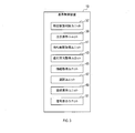
- the in-vehicle system 1 includes an HMI (Human Machine Interface) system 3, a peripheral monitoring sensor 5, a locator 7, a DCM (Data Communication Module) 9, a driving support ECU 11, and a navigation device 13. , Equipped with.
- HMI Human Machine Interface
- DCM Data Communication Module
- Each configuration of the in-vehicle system 1 is connected to each other by a communication bus 15.
- the HMI system 3 includes a head-up display (hereinafter referred to as HUD) 17, a display control device 19, a DSM (Driver Status Monitor) 21, and an operation device 23.
- HUD head-up display
- DSM Driver Status Monitor
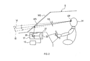
- the configuration of HUD17 will be described with reference to FIG.
- the HUD 17 is mounted on the vehicle S.
- the HUD 17 is housed in the instrument panel 27.
- HUD17 is located below the windshield WS.
- the HUD 17 includes a projector 25 and a magnifying optical system 29.
- the projector 25 acquires video data from the display control device 19.
- the projector 25 emits light corresponding to the video data toward the magnifying optical system 29.
- the magnifying optical system 29 projects the light emitted from the projector 25 onto the projection range Apr while spreading it by reflection.
- the projection range Apr is part of the windshield WS.
- the light projected on the projection range Apr is reflected toward the driver's seat side in the projection range Apr.
- the driver 31 visually recognizes the virtual image Vi superimposed on the foreground that can be seen through the projection range Apr.
- VA be the angle of view of the virtual image Vi.
- the virtual range in the space where the virtual image Vi can be imaged is defined as the image plane IS.
- the angle of view VA is a viewing angle defined by a virtual line connecting the eye point EP of the driver 31 and the outer edge of the image plane IS. Further, the angle of view VA is an angle range in which the virtual image Vi can be visually recognized when viewed from the eye point EP.
- the display control device 19 is an electronic control device that controls the display of the HUD 17.
- the display control device 19 provides video data to the HUD 17.
- the display control device 19 includes a microcomputer having a CPU 33 and, for example, a semiconductor memory such as a RAM or a ROM (hereinafter referred to as a memory 35).
- Each function of the display control device 19 is realized by the CPU 33 executing a program stored in a non-transitional substantive recording medium.
- the memory 35 corresponds to a non-transitional substantive recording medium in which a program is stored.
- the method corresponding to the program is executed.
- the display control device 19 may include one microcomputer or a plurality of microcomputers.
- the display control device 19 includes a specific state determination unit 37, an attention display unit 39, a waiting time acquisition unit 41, a traveling direction acquisition unit 43, an information acquisition unit 45, and a selection unit 47.
- a front vehicle display unit 49 and a signal display unit 51 are provided.
- the DSM21 includes a near-infrared camera and a control unit.
- the near-infrared camera captures the head of the driver 31 and generates an image.
- the control unit acquires the eye point EP and the line-of-sight direction information based on the image.
- the control unit outputs the acquired information to the display control device 19.
- the operation device 23 accepts user operations such as the driver 31. Examples of the user's operation include operations for starting and stopping the driving support function and the automatic driving function.
- the peripheral monitoring sensor 5 includes a front camera 53 and a millimeter wave radar 55.
- the peripheral monitoring sensor 5 detects a target existing around the vehicle S. Examples of the target include other vehicles, pedestrians, fixed objects, and the like.
- the locator 7 includes a GNSS receiver 57, an inertia sensor 59, a high-precision map DB 61, and a locator ECU 63.
- the GNSS receiver 57 receives positioning signals from a plurality of positioning satellites.
- the inertial sensor 59 includes a gyro sensor and an acceleration sensor.
- the high-precision map DB61 is mainly composed of a non-volatile memory.
- the high-precision map DB 61 stores map data (hereinafter referred to as high-precision map data) that is more accurate than the map data used by the navigation device 13.
- the high-precision map data includes three-dimensional shape information of a road, information on the number of lanes, information indicating an allowable traveling direction in each lane, position information of an intersection, position information of a traffic light, and the like.
- the locator ECU 63 is mainly composed of a microcomputer.
- the locator ECU 63 combines the positioning signal received by the GNSS receiver 57, the measurement result of the inertial sensor 59, the vehicle speed information acquired from the communication bus 15, and the information indicating the position and traveling direction of the vehicle S (hereinafter, locator information). To generate).
- the locator ECU 63 provides locator information and high-precision map data to the display control device 19, the navigation device 13, and the driving support ECU 11.
- the DCM9 is a communication module mounted on the vehicle S.
- the DCM9 can perform wireless communication with the communication target 65.
- Examples of the communication target 65 include other vehicles, roadside devices, mobile terminals, communication devices provided in stores, and the like.
- Examples of the mobile terminal include a smartphone carried by the driver 31.
- the driving support ECU 11 is mainly composed of a microcomputer.
- the driving support ECU 11 executes automatic driving or driving support.
- the navigation device 13 is an in-vehicle device that cooperates with the HMI system 3 to perform route guidance to a destination.
- the driver 31 can input the destination using the operation device 23.
- the specific state determination unit 37 determines whether or not the state of the vehicle S is a specific state.
- the specific state is a state in which the vehicle S is located before the red light and the vehicle speed of the vehicle S is equal to or less than a preset threshold value.
- the threshold value is, for example, 0 km / h.
- the specific state is a state in which the vehicle S is stopped before the red light.
- the specific state determination unit 37 can determine whether or not the vehicle S is located in front of the traffic light by using the locator information and the high-precision map data acquired from the locator 7. The specific state determination unit 37 can determine whether or not the state of the traffic light in front of the vehicle S is a red light based on the traffic light information acquired by using the DCM9.
- the traffic light information is information transmitted by a roadside device installed around the traffic light.
- the traffic light information is information indicating the state of the traffic light.
- the traffic light information indicates whether the state of the traffic light is a red light or a green light at the current time.
- the traffic light information is information representing a waiting time (hereinafter referred to as a signal waiting time) from the current time to the time when the state of the traffic light changes from a red light to a green light.
- step 2 If it is determined that the state of the vehicle S is a specific state, this process proceeds to step 2. If it is determined that the state of the vehicle S is not a specific state, this process repeats step 1.
- the specific state determination unit 37 determines whether or not the vehicle in front exists.
- the front vehicle is a vehicle that satisfies the following conditions.
- the vehicle in front is located in front of the vehicle S.
- the vehicle in front is located in the same traveling lane as the vehicle S.
- the vehicle in front and the vehicle S are located in front of the same traffic light.
- the specific state determination unit 37 can determine whether or not the vehicle in front exists by using the peripheral monitoring sensor 5. If it is determined that the vehicle in front does not exist, this process proceeds to step 3. If it is determined that the vehicle in front exists, this process proceeds to step 13.
- the information acquisition unit 45 executes a process of acquiring POI information using the DCM9.
- the POI information is information representing a point of interest (hereinafter referred to as POI). More specifically, the POI information is information indicating the position, type, etc. of the POI. Types of POI include, for example, stores, stations, buildings, roads, and the like.
- the POI information is transmitted by a communication device provided in a store or the like.
- the POI information corresponds to the attention display information representing the display content of the attention display.
- the selection unit 47 selects the POI information satisfying the selection criteria from the acquired POI information.
- the selection criterion is, for example, that the degree of preference of the driver 31 with respect to the POI represented by the POI information is equal to or higher than a predetermined value.
- the selection unit 47 creates selection criteria, for example, by machine learning.
- the selection unit 47 performs machine learning based on, for example, destination data set by the driver 31 in the past, past position information of the vehicle S, and the like.
- the selection unit 47 selects some POI information from the POI information satisfying the selection criteria based on the priority. For example, the closer the POI is to the vehicle S, the higher the priority. Further, for example, when the route of the vehicle S is determined, the priority of the POI related to the direction of the route is high.
- the selection unit 47 determines whether or not the selected POI information exists. If the selected POI information is present, the process proceeds to step 4. If the information acquisition unit 45 cannot acquire the POI information, or if none of the acquired POI information is selected, this process proceeds to step 7.
- step 4 the selection unit 47 determines whether or not the POI represented by the POI information exists in the angle of view VA. If the POI represented by the POI information exists in the angle of view VA, this process proceeds to step 5. If the POI represented by the POI information does not exist in the angle of view VA, this process proceeds to step 6.
- the attention display unit 39 performs the A display shown in FIG. 5 using the HUD17.
- the A display includes the display objects 67 and 69.
- the display object 67 is an arrow.
- the display object 69 is a circle.
- Display items 67 and 69 indicate POI 70.
- the POI 70 is the POI represented by the POI information selected in step 3.
- POI70 exists in the angle of view VA.
- the POI 70 is the entrance to the building.
- the A display corresponds to an attention display that urges the driver 31 to pay attention to the front.
- the attention display unit 39 performs the B display shown in FIG. 6 using the HUD 17.
- the B display shown in FIG. 6 includes the display object 71.
- the display object 71 includes an arrow and a character representing POI.
- the display object 71 indicates a POI that does not exist in the angle of view VA, such as a “bakery”, a “convenience store”, and a “station”.
- the "bakery”, "convenience store”, and "station” are POIs represented by the POI information selected in step 3.
- the B display shown in FIG. 6 corresponds to a attention display that urges the driver 31 to pay attention to the front.
- the B display may be the one shown in FIG. FIG. 7 shows only the portion of the angle of view VA.
- the B display shown in FIG. 7 includes a display object 73.
- the display object 73 includes an arrow and a character representing POI.
- Display 73 indicates POIs “No. 19”, “No. 100”, and “No. 123” that do not exist in the angle of view VA.
- "No. 19”, “No. 100”, and “No. 123” are roads.
- “No. 19”, “No. 100”, and “No. 123” are POIs represented by the POI information selected in step 3.
- the B display shown in FIG. 7 corresponds to a attention display that urges the driver 31 to pay attention to the front.
- step 7 the attention display unit 39 performs the C display shown in FIG. 8 using the HUD 17.
- the C display shown in FIG. 8 includes a display object 75.
- the display object 75 is an animation showing that the vehicle S jumps forward.
- the C display may be as shown in FIG. FIG. 9 shows only the portion of the angle of view VA.
- the C display shown in FIG. 9 includes a display object 77.
- Display 77 is an advertisement.
- C display is performed based on the advertisement information.
- the attention display unit 39 uses the DCM9 to acquire advertising information from a terminal or the like carried by the driver 31.
- the advertisement information corresponds to the attention display information indicating the display content of the attention display.
- the C display corresponds to an attention display that urges the driver 31 to pay attention to the front.
- the attention display unit 39 selects a part of the advertisement information from the advertisement information based on the priority. For example, the closer the store or the like related to the advertisement information is to the vehicle S, the higher the priority. Further, for example, when the route of the vehicle S is determined, the priority of the advertising information related to the stores and the like existing in the direction of the route is high.
- step 8 the waiting time acquisition unit 41 acquires traffic signal information using the DCM9.
- the waiting time acquisition unit 41 reads the signal waiting time from the traffic light information.
- the waiting time acquisition unit 41 determines whether or not the signal waiting time is 5 seconds or less. If the signal waiting time is 5 seconds or less, this process proceeds to step 9. If the signal waiting time exceeds 5 seconds, this process proceeds to step 3. Note that 5 seconds is an example of the threshold value.
- the threshold value may be a time other than 5 seconds.
- step 9 the attention display unit 39 ends the A display, B display, or C display that has been performed so far.
- the display material fades out, for example.
- the mode at which the display is terminated differs depending on the future traveling direction of the vehicle S.
- the displayed object fades out while advancing in the future direction of travel on the route. Further, when the navigation device 13 does not provide route guidance, the displayed object may fade out while returning to the direction of the vehicle S. Further, when the navigation device 13 does not provide route guidance, the displayed object may fade out while advancing in the traveling direction pointed to by the winker. Further, when the POI is within the angle of view VA, the displayed object may fade out while advancing in the direction of the POI.
- the future traveling direction of the vehicle S is acquired by the traveling direction acquisition unit 43.
- the traveling direction acquisition unit 43 acquires the future traveling direction of the vehicle S based on the route set by the navigation device 13, the operating state of the winker, the traveling direction allowed in the lane in which the vehicle S exists, and the like.
- step 10 the signal display unit 51 determines whether or not the following conditions J1 and J2 are satisfied.
- J2 The state in which the driving operation of the vehicle S is not performed has continued for a predetermined time or more since the time when the red light changed to the green light.
- step 10 If J1 and J2 are satisfied, this process proceeds to step 11. If J1 or J2 is not satisfied, this process repeats step 10.
- the signal display unit 51 first determines whether or not the traffic light located in front of the vehicle S is in the angle of view VA. When it is determined that the traffic light is in the angle of view VA, the signal display unit 51 uses the HUD 17 to perform the I display shown in FIG.
- the I display shown in FIG. 10 includes a display object 79.
- the display object 79 is a frame surrounding the traffic light 81.
- the display object 79 emphasizes the traffic light 81 and represents the state of the traffic light 81.
- the signal display unit 51 uses the HUD 17 to perform the I display shown in FIG.
- the I display shown in FIG. 11 includes a display object 83.
- the display object 83 is an icon imitating a traffic light 81.
- the display object 83 represents the state of the traffic light 81. For example, when the state of the traffic light 81 is a green light, the display object 83 is in the form of a green light.
- the signal display unit 51 may display a message or an arrow prompting the driver 31 to proceed when performing the I display.
- the signal display unit 51 can display the message or the arrow on the HUD 17 in time with the display of the message or the arrow on the meter.
- the signal display unit 51 can simplify the route display when performing the I display. Further, the signal display unit 51 may temporarily turn off the route display when performing the I display.
- step 12 the signal display unit 51 determines whether or not the driver 31 has taken his / her foot off the brake. When the driver 31 takes his / her foot off the brake, the I display is terminated and this process is terminated. When the I display is completed, the signal display unit 51 can return the previously simplified route display to the original state. When the I display is completed, the signal display unit 51 may temporarily turn off the route display. If the driver 31 has not taken his foot off the brake, this process proceeds to step 11.
- step 13 is the same as the process of step 3. If the selected POI information is present, the process proceeds to step 14. If the information acquisition unit 45 cannot acquire the POI information, or if none of the acquired POI information is selected, this process proceeds to step 17.
- step 14 is the same as the process of step 4. If the POI represented by the POI information exists in the angle of view VA, this process proceeds to step 15. If the POI display represented by the POI information does not exist in the angle of view VA, this process proceeds to step 16.
- the attention display unit 39 performs E display using the HUD 17.
- the E display is basically the same as the A display. However, in the case of E display, when the displayed object overlaps with the vehicle in front when viewed from the eye point EP, the attention display unit 39 does not display the displayed object.
- the E display corresponds to an attention display that urges the driver 31 to pay attention to the front.
- step 16 the attention display unit 39 performs F display using the HUD 17. In F display, the displayed object is not displayed.
- step 17 the attention display unit 39 performs D display using the HUD 17.
- the D display is the same as the C display.
- the attention display unit 39 does not display the display object 75. The reason is that since the display object 75 overlaps with the vehicle in front, the fun of displaying the display object 75 is reduced.
- step 18 is the same as the process of step 8. If the signal waiting time is 5 seconds or less, this process proceeds to step 19. If the signal waiting time exceeds 5 seconds, this process proceeds to step 13. Note that 5 seconds is an example of the threshold value. The threshold value may be a time other than 5 seconds.
- step 19 the attention display unit 39 ends the D display, E display, or F display that has been performed up to that point.
- the mode when the display ends is the same as in the case of step 9.
- step 20 the front vehicle display unit 49 determines whether or not the following conditions J3 to J5 are satisfied.
- J4 The car in front started.
- J5 The state in which the driving operation of the vehicle S is not performed continues for a predetermined time or more from the start time of the preceding vehicle.
- step 21 If all of J3 to J5 are satisfied, this process proceeds to step 21. If any one of J3 to J5 is not satisfied, this process repeats step 20.
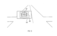
- the front vehicle display unit 49 uses the HUD 17 to perform the J display shown in FIG.
- the J display shown in FIG. 12 includes the display object 85.
- the display object 85 is a frame surrounding the front vehicle 87.
- the display 85 emphasizes the front vehicle 87.
- the form of the display object 85 may be another form.
- a display form that emphasizes the undercarriage of the front vehicle 87 and the like can be mentioned.
- the front vehicle display unit 49 may display a message or an arrow prompting the driver 31 to proceed when performing the J display.
- a message or an arrow is also displayed on the meter of the vehicle S
- the front vehicle display unit 49 can display the message or the arrow on the HUD 17 in time with the display of the message or the arrow on the meter.
- the front vehicle display unit 49 can simplify the route display when the J display is performed. Further, the front vehicle display unit 49 may temporarily turn off the route display when performing the J display.
- step 22 the front vehicle display unit 49 determines whether or not the driver 31 has taken his / her foot off the brake.
- the driver 31 takes his / her foot off the brake the J display is terminated and this process is terminated.
- the front vehicle display unit 49 can return the previously simplified route display to the original state.
- the front vehicle display unit 49 may temporarily turn off the route display. If the driver 31 has not taken his foot off the brake, this process proceeds to step 21.
- the display control device 19 acquires the signal waiting time.
- the display control device 19 ends the attention display when the signal waiting time becomes equal to or less than a preset threshold value. Therefore, when the red light changes to the green light, the driver 31 can easily see ahead.
- the display control device 19 acquires the future traveling direction of the vehicle S.
- the mode at which the attention display ends differs depending on the future traveling direction of the vehicle S. Therefore, the display control device 19 can direct the attention of the driver 31 to the future traveling direction of the vehicle S.
- the display control device 19 acquires attention display information indicating the display content of the attention display.
- the display control device 19 selects the attention display information from the acquired attention display information based on a preset standard.
- the display control device 19 performs attention display using the selected attention display information. Therefore, the attention display that is important for the driver 31 can be selected and displayed.
- the display control device 19 uses the HUD 17 to perform a display that emphasizes the vehicle in front. Therefore, the display control device 19 can prompt the driver 31 to start.
- the POI may be a destination or a place other than the destination.
- the threshold value of the signal waiting time in steps 8 and 18 may change according to the traveling lane of the vehicle S. When turning right, it takes time to start after the traffic light changes to a green light. Therefore, for example, when the traveling lane of the vehicle S is a right turn lane, the threshold value of the signal waiting time in steps 8 and 18 can be made smaller than in the case of other traveling lanes, and the display can be continued for a long time.
- the display control device 19 may have a function of detecting that the emergency vehicle is approaching the vehicle S.
- the display control device 19 can turn off the display of the HUD 17 or switch the display content of the HUD 17 to a display indicating the approach of the emergency vehicle.
- the in-vehicle system 1 may include an input unit that accepts the operation of the driver 31.
- the display control device 19 can change the display contents and the display-related settings according to the operation on the input unit.
- the display control device 19 can store the change of the setting related to the display until the ignition of the vehicle S is turned on or off.
- the driver 31 can customize the display-related settings.
- the attention display may be other than the above-mentioned display.
- the attention display is, for example, a display showing a situation in the traveling direction of the vehicle S.
- the A display, the B display, the C display, and the D display correspond to the displays showing the situation in the traveling direction of the vehicle S.
- the display control device 19 and its method described in the present disclosure are provided by configuring a processor and memory programmed to perform one or more functions embodied by a computer program. It may be realized by a dedicated computer. Alternatively, the display control device 19 and its method described in the present disclosure may be realized by a dedicated computer provided by configuring the processor with one or more dedicated hardware logic circuits. Alternatively, the display control device 19 and its method described in the present disclosure comprises a processor and memory programmed to perform one or more functions and a processor composed of one or more hardware logic circuits. It may be realized by one or more dedicated computers configured by a combination.
- the computer program may also be stored on a computer-readable non-transitional tangible recording medium as an instruction executed by the computer.
- the method for realizing the functions of each part included in the display control device 19 does not necessarily include software, and all the functions may be realized by using one or a plurality of hardware.
- a plurality of functions possessed by one component in the above embodiment may be realized by a plurality of components, or one function possessed by one component may be realized by a plurality of components. .. Further, a plurality of functions possessed by the plurality of components may be realized by one component, or one function realized by the plurality of components may be realized by one component. Further, a part of the configuration of the above embodiment may be omitted. In addition, at least a part of the configuration of the above embodiment may be added or replaced with the configuration of the other above embodiment.
- a system having the display control device 19 as a component a program for operating a computer as the display control device 19, a non-transitional non-transitional memory such as a semiconductor memory in which this program is recorded.
- a non-transitional non-transitional memory such as a semiconductor memory in which this program is recorded.
- the present disclosure can also be realized in various forms such as an actual recording medium and a display control method.
Abstract
Un dispositif de commande d'affichage (19) commande l'affichage d'un affichage tête haute (17) disposé dans un véhicule. Le dispositif de commande d'affichage est pourvu d'une unité de détermination d'état spécifique et d'une unité d'affichage attirant l'attention. L'unité de détermination d'état spécifique détermine si le véhicule est dans un état spécifique, à savoir que le véhicule est positionné devant une lumière rouge et que la vitesse du véhicule est au plus égale à un seuil prédéterminé. Si l'unité de détermination d'état spécifique détermine que le véhicule est dans l'état spécifique, l'unité d'affichage attirant l'attention utilise l'affichage tête haute pour effectuer un affichage attirant l'attention afin d'encourager le conducteur du véhicule à attirer son attention vers l'avant du véhicule.
Applications Claiming Priority (2)
| Application Number | Priority Date | Filing Date | Title |
|---|---|---|---|
| JP2019-190334 | 2019-10-17 | ||
| JP2019190334A JP2021066190A (ja) | 2019-10-17 | 2019-10-17 | 表示制御装置 |
Publications (1)
| Publication Number | Publication Date |
|---|---|
| WO2021075402A1 true WO2021075402A1 (fr) | 2021-04-22 |
Family
ID=75538507
Family Applications (1)
| Application Number | Title | Priority Date | Filing Date |
|---|---|---|---|
| PCT/JP2020/038495 WO2021075402A1 (fr) | 2019-10-17 | 2020-10-12 | Dispositif de commande d'affichage |
Country Status (2)
| Country | Link |
|---|---|
| JP (1) | JP2021066190A (fr) |
| WO (1) | WO2021075402A1 (fr) |
Citations (5)
| Publication number | Priority date | Publication date | Assignee | Title |
|---|---|---|---|---|
| WO2009157108A1 (fr) * | 2008-06-25 | 2009-12-30 | トヨタ自動車株式会社 | Appareil d'assistance à la conduite |
| JP2014235550A (ja) * | 2013-05-31 | 2014-12-15 | 日本精機株式会社 | 車載装置 |
| JP2015184432A (ja) * | 2014-03-24 | 2015-10-22 | アイシン・エィ・ダブリュ株式会社 | ヘッドアップディスプレイ装置 |
| JP2016004514A (ja) * | 2014-06-19 | 2016-01-12 | 日本精機株式会社 | 車両用表示装置 |
| JP2019104275A (ja) * | 2017-12-08 | 2019-06-27 | アルパイン株式会社 | 車載システム及び表示制御方法 |
Family Cites Families (1)
| Publication number | Priority date | Publication date | Assignee | Title |
|---|---|---|---|---|
| JP5958159B2 (ja) * | 2012-08-03 | 2016-07-27 | 日産自動車株式会社 | 車両運転支援装置及び車両運転支援方法 |
-
2019
- 2019-10-17 JP JP2019190334A patent/JP2021066190A/ja active Pending
-
2020
- 2020-10-12 WO PCT/JP2020/038495 patent/WO2021075402A1/fr active Application Filing
Patent Citations (5)
| Publication number | Priority date | Publication date | Assignee | Title |
|---|---|---|---|---|
| WO2009157108A1 (fr) * | 2008-06-25 | 2009-12-30 | トヨタ自動車株式会社 | Appareil d'assistance à la conduite |
| JP2014235550A (ja) * | 2013-05-31 | 2014-12-15 | 日本精機株式会社 | 車載装置 |
| JP2015184432A (ja) * | 2014-03-24 | 2015-10-22 | アイシン・エィ・ダブリュ株式会社 | ヘッドアップディスプレイ装置 |
| JP2016004514A (ja) * | 2014-06-19 | 2016-01-12 | 日本精機株式会社 | 車両用表示装置 |
| JP2019104275A (ja) * | 2017-12-08 | 2019-06-27 | アルパイン株式会社 | 車載システム及び表示制御方法 |
Also Published As
| Publication number | Publication date |
|---|---|
| JP2021066190A (ja) | 2021-04-30 |
Similar Documents
| Publication | Publication Date | Title |
|---|---|---|
| US20210372810A1 (en) | Display control device, display control method, and non-transitory tangible computer-readable medium therefor | |
| JP4807263B2 (ja) | 車両用表示装置 | |
| US20220130296A1 (en) | Display control device and display control program product | |
| WO2020261781A1 (fr) | Dispositif de commande d'affichage, programme de commande d'affichage et support lisible par ordinateur tangible persistant | |
| US20220289228A1 (en) | Hmi control device, hmi control method, and hmi control program product | |
| JP7218822B2 (ja) | 表示制御装置 | |
| JPWO2018056103A1 (ja) | 車両制御装置、車両制御方法、および移動体 | |
| US11200806B2 (en) | Display device, display control method, and storage medium | |
| JP2023001215A (ja) | 表示制御装置及び表示制御プログラム | |
| US11710429B2 (en) | Display control device and non-transitory computer readable storage medium for display control by head-up display | |
| US20220058998A1 (en) | Display control device and non-transitory computer-readable storage medium for display control on head-up display | |
| JP2018024363A (ja) | 車両用表示制御装置及び車両運転アシストシステム | |
| JP2019109707A (ja) | 表示制御装置、表示制御方法および車両 | |
| WO2020189238A1 (fr) | Dispositif de commande d'affichage de véhicule, procédé de commande d'affichage de véhicule et programme de commande d'affichage de véhicule | |
| CN110462699B (zh) | 车辆用显示控制装置以及车辆用显示单元 | |
| JP7127565B2 (ja) | 表示制御装置及び表示制御プログラム | |
| US20230294517A1 (en) | Vehicle display control device, display device, and vehicle display control method | |
| JP2021149319A (ja) | 表示制御装置、表示制御方法およびプログラム | |
| US20230001947A1 (en) | Information processing apparatus, vehicle, and information processing method | |
| WO2021075402A1 (fr) | Dispositif de commande d'affichage | |
| JP7173078B2 (ja) | 表示制御装置及び表示制御プログラム | |
| JP7293854B2 (ja) | 表示制御装置及び表示制御プログラム | |
| JP2021091394A (ja) | Hmi制御装置、hmi制御方法、およびhmi制御プログラム | |
| JP2021006805A (ja) | 表示制御装置及び表示制御プログラム | |
| JP2020118545A (ja) | 表示制御装置及び表示制御プログラム |
Legal Events
| Date | Code | Title | Description |
|---|---|---|---|
| 121 | Ep: the epo has been informed by wipo that ep was designated in this application |
Ref document number: 20877110 Country of ref document: EP Kind code of ref document: A1 |
|
| NENP | Non-entry into the national phase |
Ref country code: DE |
|
| 122 | Ep: pct application non-entry in european phase |
Ref document number: 20877110 Country of ref document: EP Kind code of ref document: A1 |