WO2021075402A1 - Display control device - Google Patents
Display control device Download PDFInfo
- Publication number
- WO2021075402A1 WO2021075402A1 PCT/JP2020/038495 JP2020038495W WO2021075402A1 WO 2021075402 A1 WO2021075402 A1 WO 2021075402A1 JP 2020038495 W JP2020038495 W JP 2020038495W WO 2021075402 A1 WO2021075402 A1 WO 2021075402A1
- Authority
- WO
- WIPO (PCT)
- Prior art keywords
- display
- vehicle
- control device
- attention
- display control
- Prior art date
Links
Images


Classifications
-
- B—PERFORMING OPERATIONS; TRANSPORTING
- B60—VEHICLES IN GENERAL
- B60K—ARRANGEMENT OR MOUNTING OF PROPULSION UNITS OR OF TRANSMISSIONS IN VEHICLES; ARRANGEMENT OR MOUNTING OF PLURAL DIVERSE PRIME-MOVERS IN VEHICLES; AUXILIARY DRIVES FOR VEHICLES; INSTRUMENTATION OR DASHBOARDS FOR VEHICLES; ARRANGEMENTS IN CONNECTION WITH COOLING, AIR INTAKE, GAS EXHAUST OR FUEL SUPPLY OF PROPULSION UNITS IN VEHICLES
- B60K35/00—Arrangement of adaptations of instruments
-
- G—PHYSICS
- G08—SIGNALLING
- G08G—TRAFFIC CONTROL SYSTEMS
- G08G1/00—Traffic control systems for road vehicles
- G08G1/16—Anti-collision systems
Definitions
- This disclosure relates to a display control device.
- Patent Document 1 discloses a virtual image display system for vehicles.
- the vehicle virtual image display system displays information on a traffic light hidden behind an obstacle to the user using a head-up display.
- a display control device capable of urging the driver to pay attention to the front when the vehicle is stopped before the red light.
- One aspect of the present disclosure is a display control device configured to control the display of a head-up display included in a vehicle, in which the vehicle is located in front of a red light and the vehicle speed of the vehicle is preset.
- the specific state determination unit is configured to determine whether or not the specific state is below the threshold value and the specific state determination unit is in the specific state
- the head-up display is used.
- It is a display control device including a attention display unit that displays attention to urge the driver of the vehicle to pay attention to the front.
- the display control device determines that it is in a specific state, it uses a head-up display to display attention to the driver to pay attention to the front. Therefore, the display control device, which is one aspect of the present disclosure, can urge the driver to pay attention to the front when in a specific state.
- the in-vehicle system 1 includes an HMI (Human Machine Interface) system 3, a peripheral monitoring sensor 5, a locator 7, a DCM (Data Communication Module) 9, a driving support ECU 11, and a navigation device 13. , Equipped with.
- HMI Human Machine Interface
- DCM Data Communication Module
- Each configuration of the in-vehicle system 1 is connected to each other by a communication bus 15.
- the HMI system 3 includes a head-up display (hereinafter referred to as HUD) 17, a display control device 19, a DSM (Driver Status Monitor) 21, and an operation device 23.
- HUD head-up display
- DSM Driver Status Monitor
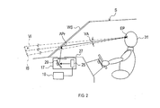
- the configuration of HUD17 will be described with reference to FIG.
- the HUD 17 is mounted on the vehicle S.
- the HUD 17 is housed in the instrument panel 27.
- HUD17 is located below the windshield WS.
- the HUD 17 includes a projector 25 and a magnifying optical system 29.
- the projector 25 acquires video data from the display control device 19.
- the projector 25 emits light corresponding to the video data toward the magnifying optical system 29.
- the magnifying optical system 29 projects the light emitted from the projector 25 onto the projection range Apr while spreading it by reflection.
- the projection range Apr is part of the windshield WS.
- the light projected on the projection range Apr is reflected toward the driver's seat side in the projection range Apr.
- the driver 31 visually recognizes the virtual image Vi superimposed on the foreground that can be seen through the projection range Apr.
- VA be the angle of view of the virtual image Vi.
- the virtual range in the space where the virtual image Vi can be imaged is defined as the image plane IS.
- the angle of view VA is a viewing angle defined by a virtual line connecting the eye point EP of the driver 31 and the outer edge of the image plane IS. Further, the angle of view VA is an angle range in which the virtual image Vi can be visually recognized when viewed from the eye point EP.
- the display control device 19 is an electronic control device that controls the display of the HUD 17.
- the display control device 19 provides video data to the HUD 17.
- the display control device 19 includes a microcomputer having a CPU 33 and, for example, a semiconductor memory such as a RAM or a ROM (hereinafter referred to as a memory 35).
- Each function of the display control device 19 is realized by the CPU 33 executing a program stored in a non-transitional substantive recording medium.
- the memory 35 corresponds to a non-transitional substantive recording medium in which a program is stored.
- the method corresponding to the program is executed.
- the display control device 19 may include one microcomputer or a plurality of microcomputers.
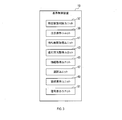
- the display control device 19 includes a specific state determination unit 37, an attention display unit 39, a waiting time acquisition unit 41, a traveling direction acquisition unit 43, an information acquisition unit 45, and a selection unit 47.
- a front vehicle display unit 49 and a signal display unit 51 are provided.
- the DSM21 includes a near-infrared camera and a control unit.
- the near-infrared camera captures the head of the driver 31 and generates an image.
- the control unit acquires the eye point EP and the line-of-sight direction information based on the image.
- the control unit outputs the acquired information to the display control device 19.
- the operation device 23 accepts user operations such as the driver 31. Examples of the user's operation include operations for starting and stopping the driving support function and the automatic driving function.
- the peripheral monitoring sensor 5 includes a front camera 53 and a millimeter wave radar 55.
- the peripheral monitoring sensor 5 detects a target existing around the vehicle S. Examples of the target include other vehicles, pedestrians, fixed objects, and the like.
- the locator 7 includes a GNSS receiver 57, an inertia sensor 59, a high-precision map DB 61, and a locator ECU 63.
- the GNSS receiver 57 receives positioning signals from a plurality of positioning satellites.
- the inertial sensor 59 includes a gyro sensor and an acceleration sensor.
- the high-precision map DB61 is mainly composed of a non-volatile memory.
- the high-precision map DB 61 stores map data (hereinafter referred to as high-precision map data) that is more accurate than the map data used by the navigation device 13.
- the high-precision map data includes three-dimensional shape information of a road, information on the number of lanes, information indicating an allowable traveling direction in each lane, position information of an intersection, position information of a traffic light, and the like.
- the locator ECU 63 is mainly composed of a microcomputer.
- the locator ECU 63 combines the positioning signal received by the GNSS receiver 57, the measurement result of the inertial sensor 59, the vehicle speed information acquired from the communication bus 15, and the information indicating the position and traveling direction of the vehicle S (hereinafter, locator information). To generate).
- the locator ECU 63 provides locator information and high-precision map data to the display control device 19, the navigation device 13, and the driving support ECU 11.
- the DCM9 is a communication module mounted on the vehicle S.
- the DCM9 can perform wireless communication with the communication target 65.
- Examples of the communication target 65 include other vehicles, roadside devices, mobile terminals, communication devices provided in stores, and the like.
- Examples of the mobile terminal include a smartphone carried by the driver 31.
- the driving support ECU 11 is mainly composed of a microcomputer.
- the driving support ECU 11 executes automatic driving or driving support.
- the navigation device 13 is an in-vehicle device that cooperates with the HMI system 3 to perform route guidance to a destination.
- the driver 31 can input the destination using the operation device 23.
- the specific state determination unit 37 determines whether or not the state of the vehicle S is a specific state.
- the specific state is a state in which the vehicle S is located before the red light and the vehicle speed of the vehicle S is equal to or less than a preset threshold value.
- the threshold value is, for example, 0 km / h.
- the specific state is a state in which the vehicle S is stopped before the red light.
- the specific state determination unit 37 can determine whether or not the vehicle S is located in front of the traffic light by using the locator information and the high-precision map data acquired from the locator 7. The specific state determination unit 37 can determine whether or not the state of the traffic light in front of the vehicle S is a red light based on the traffic light information acquired by using the DCM9.
- the traffic light information is information transmitted by a roadside device installed around the traffic light.
- the traffic light information is information indicating the state of the traffic light.
- the traffic light information indicates whether the state of the traffic light is a red light or a green light at the current time.
- the traffic light information is information representing a waiting time (hereinafter referred to as a signal waiting time) from the current time to the time when the state of the traffic light changes from a red light to a green light.
- step 2 If it is determined that the state of the vehicle S is a specific state, this process proceeds to step 2. If it is determined that the state of the vehicle S is not a specific state, this process repeats step 1.
- the specific state determination unit 37 determines whether or not the vehicle in front exists.
- the front vehicle is a vehicle that satisfies the following conditions.
- the vehicle in front is located in front of the vehicle S.
- the vehicle in front is located in the same traveling lane as the vehicle S.
- the vehicle in front and the vehicle S are located in front of the same traffic light.
- the specific state determination unit 37 can determine whether or not the vehicle in front exists by using the peripheral monitoring sensor 5. If it is determined that the vehicle in front does not exist, this process proceeds to step 3. If it is determined that the vehicle in front exists, this process proceeds to step 13.
- the information acquisition unit 45 executes a process of acquiring POI information using the DCM9.
- the POI information is information representing a point of interest (hereinafter referred to as POI). More specifically, the POI information is information indicating the position, type, etc. of the POI. Types of POI include, for example, stores, stations, buildings, roads, and the like.
- the POI information is transmitted by a communication device provided in a store or the like.
- the POI information corresponds to the attention display information representing the display content of the attention display.
- the selection unit 47 selects the POI information satisfying the selection criteria from the acquired POI information.
- the selection criterion is, for example, that the degree of preference of the driver 31 with respect to the POI represented by the POI information is equal to or higher than a predetermined value.
- the selection unit 47 creates selection criteria, for example, by machine learning.
- the selection unit 47 performs machine learning based on, for example, destination data set by the driver 31 in the past, past position information of the vehicle S, and the like.
- the selection unit 47 selects some POI information from the POI information satisfying the selection criteria based on the priority. For example, the closer the POI is to the vehicle S, the higher the priority. Further, for example, when the route of the vehicle S is determined, the priority of the POI related to the direction of the route is high.
- the selection unit 47 determines whether or not the selected POI information exists. If the selected POI information is present, the process proceeds to step 4. If the information acquisition unit 45 cannot acquire the POI information, or if none of the acquired POI information is selected, this process proceeds to step 7.
- step 4 the selection unit 47 determines whether or not the POI represented by the POI information exists in the angle of view VA. If the POI represented by the POI information exists in the angle of view VA, this process proceeds to step 5. If the POI represented by the POI information does not exist in the angle of view VA, this process proceeds to step 6.
- the attention display unit 39 performs the A display shown in FIG. 5 using the HUD17.
- the A display includes the display objects 67 and 69.
- the display object 67 is an arrow.
- the display object 69 is a circle.
- Display items 67 and 69 indicate POI 70.
- the POI 70 is the POI represented by the POI information selected in step 3.
- POI70 exists in the angle of view VA.
- the POI 70 is the entrance to the building.
- the A display corresponds to an attention display that urges the driver 31 to pay attention to the front.
- the attention display unit 39 performs the B display shown in FIG. 6 using the HUD 17.
- the B display shown in FIG. 6 includes the display object 71.
- the display object 71 includes an arrow and a character representing POI.
- the display object 71 indicates a POI that does not exist in the angle of view VA, such as a “bakery”, a “convenience store”, and a “station”.
- the "bakery”, "convenience store”, and "station” are POIs represented by the POI information selected in step 3.
- the B display shown in FIG. 6 corresponds to a attention display that urges the driver 31 to pay attention to the front.
- the B display may be the one shown in FIG. FIG. 7 shows only the portion of the angle of view VA.
- the B display shown in FIG. 7 includes a display object 73.
- the display object 73 includes an arrow and a character representing POI.
- Display 73 indicates POIs “No. 19”, “No. 100”, and “No. 123” that do not exist in the angle of view VA.
- "No. 19”, “No. 100”, and “No. 123” are roads.
- “No. 19”, “No. 100”, and “No. 123” are POIs represented by the POI information selected in step 3.
- the B display shown in FIG. 7 corresponds to a attention display that urges the driver 31 to pay attention to the front.
- step 7 the attention display unit 39 performs the C display shown in FIG. 8 using the HUD 17.
- the C display shown in FIG. 8 includes a display object 75.
- the display object 75 is an animation showing that the vehicle S jumps forward.
- the C display may be as shown in FIG. FIG. 9 shows only the portion of the angle of view VA.
- the C display shown in FIG. 9 includes a display object 77.
- Display 77 is an advertisement.
- C display is performed based on the advertisement information.
- the attention display unit 39 uses the DCM9 to acquire advertising information from a terminal or the like carried by the driver 31.
- the advertisement information corresponds to the attention display information indicating the display content of the attention display.
- the C display corresponds to an attention display that urges the driver 31 to pay attention to the front.
- the attention display unit 39 selects a part of the advertisement information from the advertisement information based on the priority. For example, the closer the store or the like related to the advertisement information is to the vehicle S, the higher the priority. Further, for example, when the route of the vehicle S is determined, the priority of the advertising information related to the stores and the like existing in the direction of the route is high.
- step 8 the waiting time acquisition unit 41 acquires traffic signal information using the DCM9.
- the waiting time acquisition unit 41 reads the signal waiting time from the traffic light information.
- the waiting time acquisition unit 41 determines whether or not the signal waiting time is 5 seconds or less. If the signal waiting time is 5 seconds or less, this process proceeds to step 9. If the signal waiting time exceeds 5 seconds, this process proceeds to step 3. Note that 5 seconds is an example of the threshold value.
- the threshold value may be a time other than 5 seconds.
- step 9 the attention display unit 39 ends the A display, B display, or C display that has been performed so far.
- the display material fades out, for example.
- the mode at which the display is terminated differs depending on the future traveling direction of the vehicle S.
- the displayed object fades out while advancing in the future direction of travel on the route. Further, when the navigation device 13 does not provide route guidance, the displayed object may fade out while returning to the direction of the vehicle S. Further, when the navigation device 13 does not provide route guidance, the displayed object may fade out while advancing in the traveling direction pointed to by the winker. Further, when the POI is within the angle of view VA, the displayed object may fade out while advancing in the direction of the POI.
- the future traveling direction of the vehicle S is acquired by the traveling direction acquisition unit 43.
- the traveling direction acquisition unit 43 acquires the future traveling direction of the vehicle S based on the route set by the navigation device 13, the operating state of the winker, the traveling direction allowed in the lane in which the vehicle S exists, and the like.
- step 10 the signal display unit 51 determines whether or not the following conditions J1 and J2 are satisfied.
- J2 The state in which the driving operation of the vehicle S is not performed has continued for a predetermined time or more since the time when the red light changed to the green light.
- step 10 If J1 and J2 are satisfied, this process proceeds to step 11. If J1 or J2 is not satisfied, this process repeats step 10.
- the signal display unit 51 first determines whether or not the traffic light located in front of the vehicle S is in the angle of view VA. When it is determined that the traffic light is in the angle of view VA, the signal display unit 51 uses the HUD 17 to perform the I display shown in FIG.
- the I display shown in FIG. 10 includes a display object 79.
- the display object 79 is a frame surrounding the traffic light 81.
- the display object 79 emphasizes the traffic light 81 and represents the state of the traffic light 81.
- the signal display unit 51 uses the HUD 17 to perform the I display shown in FIG.
- the I display shown in FIG. 11 includes a display object 83.
- the display object 83 is an icon imitating a traffic light 81.
- the display object 83 represents the state of the traffic light 81. For example, when the state of the traffic light 81 is a green light, the display object 83 is in the form of a green light.
- the signal display unit 51 may display a message or an arrow prompting the driver 31 to proceed when performing the I display.
- the signal display unit 51 can display the message or the arrow on the HUD 17 in time with the display of the message or the arrow on the meter.
- the signal display unit 51 can simplify the route display when performing the I display. Further, the signal display unit 51 may temporarily turn off the route display when performing the I display.
- step 12 the signal display unit 51 determines whether or not the driver 31 has taken his / her foot off the brake. When the driver 31 takes his / her foot off the brake, the I display is terminated and this process is terminated. When the I display is completed, the signal display unit 51 can return the previously simplified route display to the original state. When the I display is completed, the signal display unit 51 may temporarily turn off the route display. If the driver 31 has not taken his foot off the brake, this process proceeds to step 11.
- step 13 is the same as the process of step 3. If the selected POI information is present, the process proceeds to step 14. If the information acquisition unit 45 cannot acquire the POI information, or if none of the acquired POI information is selected, this process proceeds to step 17.
- step 14 is the same as the process of step 4. If the POI represented by the POI information exists in the angle of view VA, this process proceeds to step 15. If the POI display represented by the POI information does not exist in the angle of view VA, this process proceeds to step 16.
- the attention display unit 39 performs E display using the HUD 17.
- the E display is basically the same as the A display. However, in the case of E display, when the displayed object overlaps with the vehicle in front when viewed from the eye point EP, the attention display unit 39 does not display the displayed object.
- the E display corresponds to an attention display that urges the driver 31 to pay attention to the front.
- step 16 the attention display unit 39 performs F display using the HUD 17. In F display, the displayed object is not displayed.
- step 17 the attention display unit 39 performs D display using the HUD 17.
- the D display is the same as the C display.
- the attention display unit 39 does not display the display object 75. The reason is that since the display object 75 overlaps with the vehicle in front, the fun of displaying the display object 75 is reduced.
- step 18 is the same as the process of step 8. If the signal waiting time is 5 seconds or less, this process proceeds to step 19. If the signal waiting time exceeds 5 seconds, this process proceeds to step 13. Note that 5 seconds is an example of the threshold value. The threshold value may be a time other than 5 seconds.
- step 19 the attention display unit 39 ends the D display, E display, or F display that has been performed up to that point.
- the mode when the display ends is the same as in the case of step 9.
- step 20 the front vehicle display unit 49 determines whether or not the following conditions J3 to J5 are satisfied.
- J4 The car in front started.
- J5 The state in which the driving operation of the vehicle S is not performed continues for a predetermined time or more from the start time of the preceding vehicle.
- step 21 If all of J3 to J5 are satisfied, this process proceeds to step 21. If any one of J3 to J5 is not satisfied, this process repeats step 20.
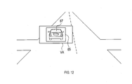
- the front vehicle display unit 49 uses the HUD 17 to perform the J display shown in FIG.
- the J display shown in FIG. 12 includes the display object 85.
- the display object 85 is a frame surrounding the front vehicle 87.
- the display 85 emphasizes the front vehicle 87.
- the form of the display object 85 may be another form.
- a display form that emphasizes the undercarriage of the front vehicle 87 and the like can be mentioned.
- the front vehicle display unit 49 may display a message or an arrow prompting the driver 31 to proceed when performing the J display.
- a message or an arrow is also displayed on the meter of the vehicle S
- the front vehicle display unit 49 can display the message or the arrow on the HUD 17 in time with the display of the message or the arrow on the meter.
- the front vehicle display unit 49 can simplify the route display when the J display is performed. Further, the front vehicle display unit 49 may temporarily turn off the route display when performing the J display.
- step 22 the front vehicle display unit 49 determines whether or not the driver 31 has taken his / her foot off the brake.
- the driver 31 takes his / her foot off the brake the J display is terminated and this process is terminated.
- the front vehicle display unit 49 can return the previously simplified route display to the original state.
- the front vehicle display unit 49 may temporarily turn off the route display. If the driver 31 has not taken his foot off the brake, this process proceeds to step 21.
- the display control device 19 acquires the signal waiting time.
- the display control device 19 ends the attention display when the signal waiting time becomes equal to or less than a preset threshold value. Therefore, when the red light changes to the green light, the driver 31 can easily see ahead.
- the display control device 19 acquires the future traveling direction of the vehicle S.
- the mode at which the attention display ends differs depending on the future traveling direction of the vehicle S. Therefore, the display control device 19 can direct the attention of the driver 31 to the future traveling direction of the vehicle S.
- the display control device 19 acquires attention display information indicating the display content of the attention display.
- the display control device 19 selects the attention display information from the acquired attention display information based on a preset standard.
- the display control device 19 performs attention display using the selected attention display information. Therefore, the attention display that is important for the driver 31 can be selected and displayed.
- the display control device 19 uses the HUD 17 to perform a display that emphasizes the vehicle in front. Therefore, the display control device 19 can prompt the driver 31 to start.
- the POI may be a destination or a place other than the destination.
- the threshold value of the signal waiting time in steps 8 and 18 may change according to the traveling lane of the vehicle S. When turning right, it takes time to start after the traffic light changes to a green light. Therefore, for example, when the traveling lane of the vehicle S is a right turn lane, the threshold value of the signal waiting time in steps 8 and 18 can be made smaller than in the case of other traveling lanes, and the display can be continued for a long time.
- the display control device 19 may have a function of detecting that the emergency vehicle is approaching the vehicle S.
- the display control device 19 can turn off the display of the HUD 17 or switch the display content of the HUD 17 to a display indicating the approach of the emergency vehicle.
- the in-vehicle system 1 may include an input unit that accepts the operation of the driver 31.
- the display control device 19 can change the display contents and the display-related settings according to the operation on the input unit.
- the display control device 19 can store the change of the setting related to the display until the ignition of the vehicle S is turned on or off.
- the driver 31 can customize the display-related settings.
- the attention display may be other than the above-mentioned display.
- the attention display is, for example, a display showing a situation in the traveling direction of the vehicle S.
- the A display, the B display, the C display, and the D display correspond to the displays showing the situation in the traveling direction of the vehicle S.
- the display control device 19 and its method described in the present disclosure are provided by configuring a processor and memory programmed to perform one or more functions embodied by a computer program. It may be realized by a dedicated computer. Alternatively, the display control device 19 and its method described in the present disclosure may be realized by a dedicated computer provided by configuring the processor with one or more dedicated hardware logic circuits. Alternatively, the display control device 19 and its method described in the present disclosure comprises a processor and memory programmed to perform one or more functions and a processor composed of one or more hardware logic circuits. It may be realized by one or more dedicated computers configured by a combination.
- the computer program may also be stored on a computer-readable non-transitional tangible recording medium as an instruction executed by the computer.
- the method for realizing the functions of each part included in the display control device 19 does not necessarily include software, and all the functions may be realized by using one or a plurality of hardware.
- a plurality of functions possessed by one component in the above embodiment may be realized by a plurality of components, or one function possessed by one component may be realized by a plurality of components. .. Further, a plurality of functions possessed by the plurality of components may be realized by one component, or one function realized by the plurality of components may be realized by one component. Further, a part of the configuration of the above embodiment may be omitted. In addition, at least a part of the configuration of the above embodiment may be added or replaced with the configuration of the other above embodiment.
- a system having the display control device 19 as a component a program for operating a computer as the display control device 19, a non-transitional non-transitional memory such as a semiconductor memory in which this program is recorded.
- a non-transitional non-transitional memory such as a semiconductor memory in which this program is recorded.
- the present disclosure can also be realized in various forms such as an actual recording medium and a display control method.
Abstract
A display control device (19) controls the display of a head-up display (17) provided in a vehicle. The display control device is provided with a specific state determining unit, and an attention-attracting display unit. The specific state determining unit determines whether the vehicle is in a specific state, namely that the vehicle is positioned ahead of a red light and the speed of the vehicle is at most equal to a predetermined threshold. If the specific state determining unit determines that the vehicle is in the specific state, the attention-attracting display unit uses the head-up display to perform an attention-attracting display to encourage the driver of the vehicle to pay attention toward the front of the vehicle.
Description
本国際出願は、2019年10月17日に日本国特許庁に出願された日本国特許出願第2019-190334号に基づく優先権を主張するものであり、日本国特許出願第2019-190334号の全内容を本国際出願に参照により援用する。
This international application claims priority based on Japanese Patent Application No. 2019-190334 filed with the Japan Patent Office on October 17, 2019, and Japanese Patent Application No. 2019-190334. The entire contents are incorporated in this international application by reference.
本開示は表示制御装置に関する。
This disclosure relates to a display control device.
特許文献1に車両用虚像表示システムが開示されている。車両用虚像表示システムは、障害物に隠れてしまった信号機の情報を、ヘッドアップディスプレイを用いてユーザに表示する。
Patent Document 1 discloses a virtual image display system for vehicles. The vehicle virtual image display system displays information on a traffic light hidden behind an obstacle to the user using a head-up display.
しかしながら、発明者の詳細な検討の結果、以下の課題が見出された。車両が赤信号の手前で停止しているとき、ドライバの注意は前方から外れやすい。そのため、信号機の状態が青信号に変化したり、前車が発進したりしたとき、ドライバがそれらに気付かず、車両の発進が遅れることがある。
However, as a result of detailed examination by the inventor, the following issues were found. When the vehicle is stopped just before the red light, the driver's attention is likely to deviate from the front. Therefore, when the state of the traffic light changes to a green light or the vehicle in front starts, the driver may not notice them and the start of the vehicle may be delayed.
本開示の1つの局面では、車両が赤信号の手前で停止しているとき等に、ドライバに対し前方に注目することを促すことができる表示制御装置を提供することが好ましい。
In one aspect of the present disclosure, it is preferable to provide a display control device capable of urging the driver to pay attention to the front when the vehicle is stopped before the red light.
本開示の1つの局面は、車両が備えるヘッドアップディスプレイの表示を制御するように構成された表示制御装置であって、前記車両が赤信号の手前に位置し、前記車両の車速が予め設定された閾値以下である特定状態であるか否かを判断するように構成された特定状態判断ユニットと、前記特定状態判断ユニットが前記特定状態であると判断した場合、前記ヘッドアップディスプレイを用いて、前記車両のドライバに対し前方に注目することを促す注目表示を行う注目表示ユニットと、を備える表示制御装置である。
One aspect of the present disclosure is a display control device configured to control the display of a head-up display included in a vehicle, in which the vehicle is located in front of a red light and the vehicle speed of the vehicle is preset. When it is determined that the specific state determination unit is configured to determine whether or not the specific state is below the threshold value and the specific state determination unit is in the specific state, the head-up display is used. It is a display control device including a attention display unit that displays attention to urge the driver of the vehicle to pay attention to the front.
本開示の1つの局面である表示制御装置は、特定状態であると判断した場合、ヘッドアップディスプレイを用いて、ドライバに対し前方に注目することを促す注目表示を行う。そのため、本開示の1つの局面である表示制御装置は、特定状態である場合、ドライバに対し前方に注目することを促すことができる。
When the display control device, which is one aspect of the present disclosure, determines that it is in a specific state, it uses a head-up display to display attention to the driver to pay attention to the front. Therefore, the display control device, which is one aspect of the present disclosure, can urge the driver to pay attention to the front when in a specific state.
本開示の例示的な実施形態について図面を参照しながら説明する。
<第1実施形態>
1.車載システム1の構成
車載システム1の構成を、図1~図3に基づき説明する。車載システム1は車両に搭載されている。車載システム1を搭載している車両を以下では車両Sとする。 An exemplary embodiment of the present disclosure will be described with reference to the drawings.
<First Embodiment>
1. 1. Configuration of the in-vehicle system 1 The configuration of the in-vehicle system 1 will be described with reference to FIGS. 1 to 3. The in-vehicle system 1 is mounted on the vehicle. The vehicle equipped with the in-vehicle system 1 will be referred to as a vehicle S below.
<第1実施形態>
1.車載システム1の構成
車載システム1の構成を、図1~図3に基づき説明する。車載システム1は車両に搭載されている。車載システム1を搭載している車両を以下では車両Sとする。 An exemplary embodiment of the present disclosure will be described with reference to the drawings.
<First Embodiment>
1. 1. Configuration of the in-
図1に示すように、車載システム1は、HMI(Human Machine Interface)システム3と、周辺監視センサ5と、ロケータ7と、DCM(Data Communication Module)9と、運転支援ECU11と、ナビゲーション装置13と、を備える。車載システム1の各構成は、通信バス15により相互に接続されている。
As shown in FIG. 1, the in-vehicle system 1 includes an HMI (Human Machine Interface) system 3, a peripheral monitoring sensor 5, a locator 7, a DCM (Data Communication Module) 9, a driving support ECU 11, and a navigation device 13. , Equipped with. Each configuration of the in-vehicle system 1 is connected to each other by a communication bus 15.
HMIシステム3は、ヘッドアップディスプレイ(以下ではHUDとする)17と、表示制御装置19と、DSM(Driver Status Monitor)21と、操作デバイス23と、を備える。
The HMI system 3 includes a head-up display (hereinafter referred to as HUD) 17, a display control device 19, a DSM (Driver Status Monitor) 21, and an operation device 23.
HUD17の構成を図2に基づき説明する。HUD17は車両Sに搭載されている。HUD17はインスツルメントパネル27の中に収容されている。HUD17はウインドシールドWSの下方に位置する。
The configuration of HUD17 will be described with reference to FIG. The HUD 17 is mounted on the vehicle S. The HUD 17 is housed in the instrument panel 27. HUD17 is located below the windshield WS.
HUD17は、プロジェクタ25と拡大光学系29とを備える。プロジェクタ25は、表示制御装置19から映像データを取得する。プロジェクタ25は、映像データに対応する光を拡大光学系29に向けて射出する。
The HUD 17 includes a projector 25 and a magnifying optical system 29. The projector 25 acquires video data from the display control device 19. The projector 25 emits light corresponding to the video data toward the magnifying optical system 29.
拡大光学系29は、プロジェクタ25から射出された光を、反射によって広げつつ、投影範囲Aprに投影する。投影範囲AprはウインドシールドWSの一部である。投影範囲Aprに投影された光は、投影範囲Aprにおいて運転席側に反射される。ドライバ31は、投影範囲Aprを通して見える前景に重畳された虚像Viを視認する。虚像Viの画角をVAとする。虚像Viを結像可能な空間中の仮想範囲を結像面ISとする。画角VAは、ドライバ31のアイポイントEPと結像面ISの外縁とを結ぶ仮想線により規定される視野角である。また、画角VAは、アイポイントEPから見て、虚像Viを視認できる角度範囲である。
The magnifying optical system 29 projects the light emitted from the projector 25 onto the projection range Apr while spreading it by reflection. The projection range Apr is part of the windshield WS. The light projected on the projection range Apr is reflected toward the driver's seat side in the projection range Apr. The driver 31 visually recognizes the virtual image Vi superimposed on the foreground that can be seen through the projection range Apr. Let VA be the angle of view of the virtual image Vi. The virtual range in the space where the virtual image Vi can be imaged is defined as the image plane IS. The angle of view VA is a viewing angle defined by a virtual line connecting the eye point EP of the driver 31 and the outer edge of the image plane IS. Further, the angle of view VA is an angle range in which the virtual image Vi can be visually recognized when viewed from the eye point EP.
表示制御装置19は、HUD17の表示を制御する電子制御装置である。表示制御装置19は、HUD17に映像データを提供する。表示制御装置19は、CPU33と、例えば、RAM又はROM等の半導体メモリ(以下、メモリ35とする)と、を有するマイクロコンピュータを備える。
The display control device 19 is an electronic control device that controls the display of the HUD 17. The display control device 19 provides video data to the HUD 17. The display control device 19 includes a microcomputer having a CPU 33 and, for example, a semiconductor memory such as a RAM or a ROM (hereinafter referred to as a memory 35).
表示制御装置19の各機能は、CPU33が非遷移的実体的記録媒体に格納されたプログラムを実行することにより実現される。この例では、メモリ35が、プログラムを格納した非遷移的実体的記録媒体に該当する。また、このプログラムが実行されることで、プログラムに対応する方法が実行される。なお、表示制御装置19は、1つのマイクロコンピュータを備えてもよいし、複数のマイクロコンピュータを備えてもよい。
Each function of the display control device 19 is realized by the CPU 33 executing a program stored in a non-transitional substantive recording medium. In this example, the memory 35 corresponds to a non-transitional substantive recording medium in which a program is stored. Moreover, when this program is executed, the method corresponding to the program is executed. The display control device 19 may include one microcomputer or a plurality of microcomputers.
表示制御装置19は、図3に示すように、特定状態判断ユニット37と、注目表示ユニット39と、待ち時間取得ユニット41と、進行方向取得ユニット43と、情報取得ユニット45と、選択ユニット47と、前車表示ユニット49と、信号表示ユニット51と、を備える。
As shown in FIG. 3, the display control device 19 includes a specific state determination unit 37, an attention display unit 39, a waiting time acquisition unit 41, a traveling direction acquisition unit 43, an information acquisition unit 45, and a selection unit 47. A front vehicle display unit 49 and a signal display unit 51 are provided.
DSM21は、近赤外線カメラと、制御ユニットとを備える。近赤外線カメラはドライバ31の頭部を撮影し、画像を生成する。制御ユニットは、画像に基づき、アイポイントEP及び視線方向の情報を取得する。制御ユニットは、取得した情報を表示制御装置19に出力する。
The DSM21 includes a near-infrared camera and a control unit. The near-infrared camera captures the head of the driver 31 and generates an image. The control unit acquires the eye point EP and the line-of-sight direction information based on the image. The control unit outputs the acquired information to the display control device 19.
操作デバイス23は、ドライバ31等のユーザの操作を受け付ける。ユーザの操作として、例えば、運転支援機能や自動運転機能の起動及び停止の操作等が挙げられる。
The operation device 23 accepts user operations such as the driver 31. Examples of the user's operation include operations for starting and stopping the driving support function and the automatic driving function.
周辺監視センサ5は、フロントカメラ53及びミリ波レーダ55を備える。周辺監視センサ5は、車両Sの周囲に存在する物標を検出する。物標として、例えば、他の車両、歩行者、固定物等が挙げられる。
The peripheral monitoring sensor 5 includes a front camera 53 and a millimeter wave radar 55. The peripheral monitoring sensor 5 detects a target existing around the vehicle S. Examples of the target include other vehicles, pedestrians, fixed objects, and the like.
ロケータ7は、GNSS受信機57と、慣性センサ59と、高精度地図DB61と、ロケータECU63と、を備える。GNSS受信機57は、複数の測位衛星から測位信号を受信する。慣性センサ59は、ジャイロセンサ及び加速度センサを備える。
The locator 7 includes a GNSS receiver 57, an inertia sensor 59, a high-precision map DB 61, and a locator ECU 63. The GNSS receiver 57 receives positioning signals from a plurality of positioning satellites. The inertial sensor 59 includes a gyro sensor and an acceleration sensor.
高精度地図DB61は不揮発性メモリを主体に構成されている。高精度地図DB61は、ナビゲーション装置13が使用する地図データよりも高精度な地図データ(以下では高精度地図データとする)を記憶している。高精度地図データは、道路の3次元形状情報、レーン数情報、各レーンにおいて許容される進行方向を表す情報、交差点の位置情報、及び、信号機の位置情報等を含んでいる。
The high-precision map DB61 is mainly composed of a non-volatile memory. The high-precision map DB 61 stores map data (hereinafter referred to as high-precision map data) that is more accurate than the map data used by the navigation device 13. The high-precision map data includes three-dimensional shape information of a road, information on the number of lanes, information indicating an allowable traveling direction in each lane, position information of an intersection, position information of a traffic light, and the like.
ロケータECU63は、マイクロコンピュータを主体に構成される。ロケータECU63は、GNSS受信機57が受信する測位信号、慣性センサ59の計測結果、通信バス15から取得した車速情報等を組み合わせることで、車両Sの位置及び進行方向を表す情報(以下ではロケータ情報とする)を生成する。ロケータECU63は、ロケータ情報及び高精度地図データを、表示制御装置19、ナビゲーション装置13、及び運転支援ECU11に提供する。
The locator ECU 63 is mainly composed of a microcomputer. The locator ECU 63 combines the positioning signal received by the GNSS receiver 57, the measurement result of the inertial sensor 59, the vehicle speed information acquired from the communication bus 15, and the information indicating the position and traveling direction of the vehicle S (hereinafter, locator information). To generate). The locator ECU 63 provides locator information and high-precision map data to the display control device 19, the navigation device 13, and the driving support ECU 11.
DCM9は、車両Sに搭載される通信モジュールである。DCM9は、通信対象65との間で無線通信を行うことができる。通信対象65として、例えば、他の車両、路側装置、携帯端末、店舗が備える通信装置等が挙げられる。携帯端末として、例えば、ドライバ31が携帯するスマートフォン等が挙げられる。
DCM9 is a communication module mounted on the vehicle S. The DCM9 can perform wireless communication with the communication target 65. Examples of the communication target 65 include other vehicles, roadside devices, mobile terminals, communication devices provided in stores, and the like. Examples of the mobile terminal include a smartphone carried by the driver 31.
運転支援ECU11は、マイクロコンピュータを主体に構成される。運転支援ECU11は、自動運転又は運転支援を実行する。ナビゲーション装置13は、HMIシステム3と連携し、目的地までのルート案内を実行する車載装置である。ドライバ31は、操作デバイス23を用いて目的地を入力することができる。
The driving support ECU 11 is mainly composed of a microcomputer. The driving support ECU 11 executes automatic driving or driving support. The navigation device 13 is an in-vehicle device that cooperates with the HMI system 3 to perform route guidance to a destination. The driver 31 can input the destination using the operation device 23.
2.表示制御装置19が実行する処理
表示制御装置19が実行する処理を、図4~図12に基づき説明する。図4のステップ1では、車両Sの状態が特定状態であるか否かを、特定状態判断ユニット37が判断する。特定状態とは、車両Sが赤信号の手前に位置し、車両Sの車速が予め設定された閾値以下である状態である。閾値は、例えば、0Km/hである。閾値が0Km/hである場合、特定状態は、車両Sが赤信号の手前で停止している状態である。 2. Processing executed by thedisplay control device 19 The processing executed by the display control device 19 will be described with reference to FIGS. 4 to 12. In step 1 of FIG. 4, the specific state determination unit 37 determines whether or not the state of the vehicle S is a specific state. The specific state is a state in which the vehicle S is located before the red light and the vehicle speed of the vehicle S is equal to or less than a preset threshold value. The threshold value is, for example, 0 km / h. When the threshold value is 0 km / h, the specific state is a state in which the vehicle S is stopped before the red light.
表示制御装置19が実行する処理を、図4~図12に基づき説明する。図4のステップ1では、車両Sの状態が特定状態であるか否かを、特定状態判断ユニット37が判断する。特定状態とは、車両Sが赤信号の手前に位置し、車両Sの車速が予め設定された閾値以下である状態である。閾値は、例えば、0Km/hである。閾値が0Km/hである場合、特定状態は、車両Sが赤信号の手前で停止している状態である。 2. Processing executed by the
特定状態判断ユニット37は、ロケータ7から取得したロケータ情報及び高精度地図データを用いて、車両Sが信号機の手前に位置しているか否かを判断することができる。特定状態判断ユニット37は、DCM9を用いて取得した信号機情報に基づき、車両Sの前方にある信号機の状態が赤信号であるか否かを判断することができる。
The specific state determination unit 37 can determine whether or not the vehicle S is located in front of the traffic light by using the locator information and the high-precision map data acquired from the locator 7. The specific state determination unit 37 can determine whether or not the state of the traffic light in front of the vehicle S is a red light based on the traffic light information acquired by using the DCM9.
なお、信号機情報は、信号機の周辺に設置された路側装置が送信する情報である。信号機情報は、信号機の状態を表す情報である。信号機情報は、信号機の状態が、現在時刻において赤信号及び青信号のいずれであるかを表す。また、信号機情報は、現在時刻から、信号機の状態が赤信号から青信号に変わる時刻までの待ち時間(以下では信号待ち時間とする)を表す情報である。
The traffic light information is information transmitted by a roadside device installed around the traffic light. The traffic light information is information indicating the state of the traffic light. The traffic light information indicates whether the state of the traffic light is a red light or a green light at the current time. Further, the traffic light information is information representing a waiting time (hereinafter referred to as a signal waiting time) from the current time to the time when the state of the traffic light changes from a red light to a green light.
車両Sの状態が特定状態であると判断した場合、本処理はステップ2に進む。車両Sの状態が特定状態ではないと判断した場合、本処理はステップ1を繰り返す。
If it is determined that the state of the vehicle S is a specific state, this process proceeds to step 2. If it is determined that the state of the vehicle S is not a specific state, this process repeats step 1.
ステップ2では、前車が存在するか否かを特定状態判断ユニット37が判断する。前車とは、以下の条件を満たす車両である。前車は車両Sの前方に位置する。前車は車両Sと同じ走行レーンに位置する。前車及び車両Sは、同一の信号機の手前に位置する。
In step 2, the specific state determination unit 37 determines whether or not the vehicle in front exists. The front vehicle is a vehicle that satisfies the following conditions. The vehicle in front is located in front of the vehicle S. The vehicle in front is located in the same traveling lane as the vehicle S. The vehicle in front and the vehicle S are located in front of the same traffic light.
特定状態判断ユニット37は、周辺監視センサ5を用いて前車が存在するか否かを判断できる。前車が存在しないと判断した場合、本処理はステップ3に進む。前車が存在すると判断した場合、本処理はステップ13に進む。
The specific state determination unit 37 can determine whether or not the vehicle in front exists by using the peripheral monitoring sensor 5. If it is determined that the vehicle in front does not exist, this process proceeds to step 3. If it is determined that the vehicle in front exists, this process proceeds to step 13.
ステップ3では、まず、情報取得ユニット45が、DCM9を用いて、POI情報を取得する処理を実行する。POI情報とは、ポイントオブインタレスト(以下ではPOIとする)を表す情報である。さらに詳しくは、POI情報は、POIの位置、種類等を表す情報である。POIの種類として、例えば、店舗、駅、建物、道路等がある。なお、POI情報は、店舗等が備える通信装置により送信される。POI情報は、注目表示の表示内容を表す注目表示情報に対応する。
In step 3, first, the information acquisition unit 45 executes a process of acquiring POI information using the DCM9. The POI information is information representing a point of interest (hereinafter referred to as POI). More specifically, the POI information is information indicating the position, type, etc. of the POI. Types of POI include, for example, stores, stations, buildings, roads, and the like. The POI information is transmitted by a communication device provided in a store or the like. The POI information corresponds to the attention display information representing the display content of the attention display.
情報取得ユニット45がPOI情報を取得できた場合、選択ユニット47は、取得されたPOI情報の中から、選択基準を満たすPOI情報を選択する。選択基準は、例えば、POI情報が表すPOIに対するドライバ31の好みの程度が所定値以上であることである。選択ユニット47は、例えば、機械学習により、選択基準を作成する。選択ユニット47は、例えば、過去にドライバ31が設定した目的地のデータ、車両Sの過去の位置情報等に基づき、機械学習を行う。
When the information acquisition unit 45 can acquire the POI information, the selection unit 47 selects the POI information satisfying the selection criteria from the acquired POI information. The selection criterion is, for example, that the degree of preference of the driver 31 with respect to the POI represented by the POI information is equal to or higher than a predetermined value. The selection unit 47 creates selection criteria, for example, by machine learning. The selection unit 47 performs machine learning based on, for example, destination data set by the driver 31 in the past, past position information of the vehicle S, and the like.
選択基準を満たすPOI情報の数が上限値を超える場合、選択ユニット47は、優先度に基づき、選択基準を満たすPOI情報の中から、一部のPOI情報をさらに選択する。優先度は、例えば、POIが車両Sに近いほど高い。また、例えば、車両Sのルートが決まっている場合、ルートの方向に関連するPOIの優先度は高い。
When the number of POI information satisfying the selection criteria exceeds the upper limit, the selection unit 47 further selects some POI information from the POI information satisfying the selection criteria based on the priority. For example, the closer the POI is to the vehicle S, the higher the priority. Further, for example, when the route of the vehicle S is determined, the priority of the POI related to the direction of the route is high.
選択ユニット47は、選択されたPOI情報が存在するか否かを判断する。選択されたPOI情報が存在する場合、本処理はステップ4に進む。情報取得ユニット45がPOI情報を取得できなかった場合、又は、取得されたPOI情報のいずれもが選択されなかった場合、本処理はステップ7に進む。
The selection unit 47 determines whether or not the selected POI information exists. If the selected POI information is present, the process proceeds to step 4. If the information acquisition unit 45 cannot acquire the POI information, or if none of the acquired POI information is selected, this process proceeds to step 7.
ステップ4では、POI情報が表すPOIが、画角VAの中に存在するか否かを選択ユニット47が判断する。POI情報が表すPOIが画角VAの中に存在する場合、本処理はステップ5に進む。POI情報が表すPOIが画角VAの中に存在しない場合、本処理はステップ6に進む。
In step 4, the selection unit 47 determines whether or not the POI represented by the POI information exists in the angle of view VA. If the POI represented by the POI information exists in the angle of view VA, this process proceeds to step 5. If the POI represented by the POI information does not exist in the angle of view VA, this process proceeds to step 6.
ステップ5では、注目表示ユニット39が、HUD17を用いて、図5に示すA表示を行う。A表示は、表示物67、69を含む。図5に示す事例では、表示物67は矢印である。表示物69は丸である。表示物67、69は、POI70を示している。POI70は、前記ステップ3において選択されたPOI情報が表すPOIである。POI70は画角VAの中に存在する。図5に示す事例では、POI70は建物の入口である。A表示は、ドライバ31に対し前方に注目することを促す注目表示に対応する。
In step 5, the attention display unit 39 performs the A display shown in FIG. 5 using the HUD17. The A display includes the display objects 67 and 69. In the example shown in FIG. 5, the display object 67 is an arrow. The display object 69 is a circle. Display items 67 and 69 indicate POI 70. The POI 70 is the POI represented by the POI information selected in step 3. POI70 exists in the angle of view VA. In the example shown in FIG. 5, the POI 70 is the entrance to the building. The A display corresponds to an attention display that urges the driver 31 to pay attention to the front.
ステップ6では、注目表示ユニット39が、HUD17を用いて、図6に示すB表示を行う。図6に示すB表示は、表示物71を含む。図6に示す事例では、表示物71は、矢印と、POIを表す文字とを含む。表示物71は、画角VAの中に存在しないPOIである「パン屋」、「コンビニ」、及び「駅」を示している。「パン屋」、「コンビニ」、及び「駅」は、前記ステップ3において選択されたPOI情報が表すPOIである。図6に示すB表示は、ドライバ31に対し前方に注目することを促す注目表示に対応する。
In step 6, the attention display unit 39 performs the B display shown in FIG. 6 using the HUD 17. The B display shown in FIG. 6 includes the display object 71. In the example shown in FIG. 6, the display object 71 includes an arrow and a character representing POI. The display object 71 indicates a POI that does not exist in the angle of view VA, such as a “bakery”, a “convenience store”, and a “station”. The "bakery", "convenience store", and "station" are POIs represented by the POI information selected in step 3. The B display shown in FIG. 6 corresponds to a attention display that urges the driver 31 to pay attention to the front.
B表示は、図7に示すものであってもよい。図7は、画角VAの部分のみを示す。図7に示すB表示は、表示物73を含む。図7に示す事例では、表示物73は、矢印と、POIを表す文字とを含む。表示物73は、画角VAの中に存在しないPOIである「19号」、「100号」、及び「123号」を示している。「19号」、「100号」、及び「123号」は道路である。「19号」、「100号」、及び「123号」は、前記ステップ3において選択されたPOI情報が表すPOIである。図7に示すB表示は、ドライバ31に対し前方に注目することを促す注目表示に対応する。
The B display may be the one shown in FIG. FIG. 7 shows only the portion of the angle of view VA. The B display shown in FIG. 7 includes a display object 73. In the example shown in FIG. 7, the display object 73 includes an arrow and a character representing POI. Display 73 indicates POIs “No. 19”, “No. 100”, and “No. 123” that do not exist in the angle of view VA. "No. 19", "No. 100", and "No. 123" are roads. “No. 19”, “No. 100”, and “No. 123” are POIs represented by the POI information selected in step 3. The B display shown in FIG. 7 corresponds to a attention display that urges the driver 31 to pay attention to the front.
ステップ7では、注目表示ユニット39が、HUD17を用いて、図8に示すC表示を行う。図8に示すC表示は、表示物75を含む。表示物75は、車両Sが前方に飛び出ることを表すアニメーションである。
In step 7, the attention display unit 39 performs the C display shown in FIG. 8 using the HUD 17. The C display shown in FIG. 8 includes a display object 75. The display object 75 is an animation showing that the vehicle S jumps forward.
C表示は、図9に示すものであってもよい。図9は、画角VAの部分のみを示す。図9に示すC表示は、表示物77を含む。表示物77は広告である。C表示は、広告情報に基づき行われる。注目表示ユニット39は、DCM9を用いて、ドライバ31が携帯する端末等から、広告情報を取得する。広告情報は、注目表示の表示内容を表す注目表示情報に対応する。C表示は、ドライバ31に対し前方に注目することを促す注目表示に対応する。
The C display may be as shown in FIG. FIG. 9 shows only the portion of the angle of view VA. The C display shown in FIG. 9 includes a display object 77. Display 77 is an advertisement. C display is performed based on the advertisement information. The attention display unit 39 uses the DCM9 to acquire advertising information from a terminal or the like carried by the driver 31. The advertisement information corresponds to the attention display information indicating the display content of the attention display. The C display corresponds to an attention display that urges the driver 31 to pay attention to the front.
広告情報の数が上限値を超える場合、注目表示ユニット39は、優先度に基づき、広告情報の中から、一部の広告情報を選択する。優先度は、例えば、広告情報に関連する店舗等が車両Sに近いほど高い。また、例えば、車両Sのルートが決まっている場合、ルートの方向に存在する店舗等に関連する広告情報の優先度は高い。
When the number of advertisement information exceeds the upper limit, the attention display unit 39 selects a part of the advertisement information from the advertisement information based on the priority. For example, the closer the store or the like related to the advertisement information is to the vehicle S, the higher the priority. Further, for example, when the route of the vehicle S is determined, the priority of the advertising information related to the stores and the like existing in the direction of the route is high.
ステップ8では、待ち時間取得ユニット41が、DCM9を用いて信号機情報を取得する。次に、待ち時間取得ユニット41は、信号機情報から、信号待ち時間を読み出す。待ち時間取得ユニット41は、信号待ち時間が5秒間以下であるか否かを判断する。信号待ち時間が5秒間以下である場合、本処理はステップ9に進む。信号待ち時間が5秒間を超える場合、本処理はステップ3に進む。なお、5秒間は閾値の例示である。閾値は5秒間以外の時間であってもよい。
In step 8, the waiting time acquisition unit 41 acquires traffic signal information using the DCM9. Next, the waiting time acquisition unit 41 reads the signal waiting time from the traffic light information. The waiting time acquisition unit 41 determines whether or not the signal waiting time is 5 seconds or less. If the signal waiting time is 5 seconds or less, this process proceeds to step 9. If the signal waiting time exceeds 5 seconds, this process proceeds to step 3. Note that 5 seconds is an example of the threshold value. The threshold value may be a time other than 5 seconds.
ステップ9では、注目表示ユニット39が、それまで行っていたA表示、B表示、又はC表示を終了する。表示が終了するとき、表示物は、例えば、フェードアウトする。表示を終了するときの態様は、車両Sの将来の進行方向に応じて異なる。
In step 9, the attention display unit 39 ends the A display, B display, or C display that has been performed so far. When the display ends, the display material fades out, for example. The mode at which the display is terminated differs depending on the future traveling direction of the vehicle S.
例えば、ナビゲーション装置13がルート案内をしている場合、表示物は、ルートにおける将来の進行方向に進みながらフェードアウトする。また、ナビゲーション装置13がルート案内をしていない場合、表示物は、車両Sの方向に戻りながらフェードアウトしてもよい。また、ナビゲーション装置13がルート案内をしていない場合、表示物は、ウインカが指す進行方向に進みながらフェードアウトしてもよい。また、POIが画角VA内にある場合、表示物は、POIの方向に進みながらフェードアウトしてもよい。
For example, when the navigation device 13 is providing route guidance, the displayed object fades out while advancing in the future direction of travel on the route. Further, when the navigation device 13 does not provide route guidance, the displayed object may fade out while returning to the direction of the vehicle S. Further, when the navigation device 13 does not provide route guidance, the displayed object may fade out while advancing in the traveling direction pointed to by the winker. Further, when the POI is within the angle of view VA, the displayed object may fade out while advancing in the direction of the POI.
なお、車両Sの将来の進行方向は、進行方向取得ユニット43により取得される。進行方向取得ユニット43は、ナビゲーション装置13が設定したルート、ウインカの作動状態、車両Sが存在するレーンにおいて許容される進行方向等に基づき、車両Sの将来の進行方向を取得する。
The future traveling direction of the vehicle S is acquired by the traveling direction acquisition unit 43. The traveling direction acquisition unit 43 acquires the future traveling direction of the vehicle S based on the route set by the navigation device 13, the operating state of the winker, the traveling direction allowed in the lane in which the vehicle S exists, and the like.
ステップ10では、以下の条件J1及びJ2が充足されるか否かを、信号表示ユニット51が判断する。
In step 10, the signal display unit 51 determines whether or not the following conditions J1 and J2 are satisfied.
J1:特定状態且つ前車が存在しない状態の後、赤信号が青信号に変わった。
J1: After a specific condition and no vehicle in front, the red light changed to a green light.
J2:車両Sの運転操作がなされてない状態が、赤信号が青信号に変わった時刻から所定時間以上継続している。
J2: The state in which the driving operation of the vehicle S is not performed has continued for a predetermined time or more since the time when the red light changed to the green light.
J1及びJ2が充足される場合、本処理はステップ11に進む。J1又はJ2が充足されない場合、本処理はステップ10を繰り返す。
If J1 and J2 are satisfied, this process proceeds to step 11. If J1 or J2 is not satisfied, this process repeats step 10.
ステップ11では、まず、車両Sの前方に位置する信号機が画角VAの中にあるか否かを信号表示ユニット51が判断する。信号機が画角VAの中にあると判断した場合、信号表示ユニット51は、HUD17を用いて、図10に示すI表示を行う。図10に示すI表示は、表示物79を含む。図10に示す事例では、表示物79は、信号機81を囲む枠である。表示物79は、信号機81を強調し、信号機81の状態を表している。
In step 11, the signal display unit 51 first determines whether or not the traffic light located in front of the vehicle S is in the angle of view VA. When it is determined that the traffic light is in the angle of view VA, the signal display unit 51 uses the HUD 17 to perform the I display shown in FIG. The I display shown in FIG. 10 includes a display object 79. In the example shown in FIG. 10, the display object 79 is a frame surrounding the traffic light 81. The display object 79 emphasizes the traffic light 81 and represents the state of the traffic light 81.
信号機が画角VAの中にないと判断した場合、信号表示ユニット51は、HUD17を用いて、図11に示すI表示を行う。図11に示すI表示は、表示物83を含む。図11に示す事例では、表示物83は、信号機81を模したアイコンである。表示物83は、信号機81の状態を表している。例えば、信号機81の状態が青信号である場合、表示物83は青信号の態様となる。
When it is determined that the traffic light is not in the angle of view VA, the signal display unit 51 uses the HUD 17 to perform the I display shown in FIG. The I display shown in FIG. 11 includes a display object 83. In the example shown in FIG. 11, the display object 83 is an icon imitating a traffic light 81. The display object 83 represents the state of the traffic light 81. For example, when the state of the traffic light 81 is a green light, the display object 83 is in the form of a green light.
信号表示ユニット51は、I表示を行うとき、ドライバ31に対し進行を促すメッセージや矢印を表示してもよい。車両Sのメータにもメッセージや矢印が表示される場合、信号表示ユニット51は、メータにおけるメッセージや矢印の表示とタイミングを合わせて、HUD17にメッセージや矢印を表示することができる。信号表示ユニット51は、I表示を行うとき、ルート表示を簡易化することができる。また、信号表示ユニット51は、I表示を行うとき、ルート表示を一時的に消してもよい。
The signal display unit 51 may display a message or an arrow prompting the driver 31 to proceed when performing the I display. When a message or an arrow is also displayed on the meter of the vehicle S, the signal display unit 51 can display the message or the arrow on the HUD 17 in time with the display of the message or the arrow on the meter. The signal display unit 51 can simplify the route display when performing the I display. Further, the signal display unit 51 may temporarily turn off the route display when performing the I display.
ステップ12では、ドライバ31がブレーキから足を離したか否かを、信号表示ユニット51が判断する。ドライバ31がブレーキから足を離した場合、I表示を終了し、本処理を終了する。I表示が終了したとき、信号表示ユニット51は、それまで簡易化していたルート表示を元の状態に戻すことができる。I表示が終了したとき、信号表示ユニット51は、ルート表示を一時的に消してもよい。ドライバ31がブレーキから足を離していない場合、本処理はステップ11に進む。
In step 12, the signal display unit 51 determines whether or not the driver 31 has taken his / her foot off the brake. When the driver 31 takes his / her foot off the brake, the I display is terminated and this process is terminated. When the I display is completed, the signal display unit 51 can return the previously simplified route display to the original state. When the I display is completed, the signal display unit 51 may temporarily turn off the route display. If the driver 31 has not taken his foot off the brake, this process proceeds to step 11.
ステップ13の処理は前記ステップ3の処理と同様である。選択されたPOI情報が存在する場合、本処理はステップ14に進む。情報取得ユニット45がPOI情報を取得できなかった場合、又は、取得されたPOI情報のいずれもが選択されなかった場合、本処理はステップ17に進む。
The process of step 13 is the same as the process of step 3. If the selected POI information is present, the process proceeds to step 14. If the information acquisition unit 45 cannot acquire the POI information, or if none of the acquired POI information is selected, this process proceeds to step 17.
ステップ14の処理は、前記ステップ4の処理と同様である。POI情報が表すPOIが画角VAの中に存在する場合、本処理はステップ15に進む。POI情報が表すPOI表示が画角VAの中に存在しない場合、本処理はステップ16に進む。
The process of step 14 is the same as the process of step 4. If the POI represented by the POI information exists in the angle of view VA, this process proceeds to step 15. If the POI display represented by the POI information does not exist in the angle of view VA, this process proceeds to step 16.
ステップ15では、注目表示ユニット39が、HUD17を用いて、E表示を行う。E表示は、基本的にはA表示と同様である。ただし、E表示の場合、アイポイントEPから見て、表示物が前車と重なるとき、注目表示ユニット39は表示物を表示しない。E表示は、ドライバ31に対し前方に注目することを促す注目表示に対応する。
In step 15, the attention display unit 39 performs E display using the HUD 17. The E display is basically the same as the A display. However, in the case of E display, when the displayed object overlaps with the vehicle in front when viewed from the eye point EP, the attention display unit 39 does not display the displayed object. The E display corresponds to an attention display that urges the driver 31 to pay attention to the front.
ステップ16では、注目表示ユニット39が、HUD17を用いて、F表示を行う。F表示では、表示物を表示しない。
In step 16, the attention display unit 39 performs F display using the HUD 17. In F display, the displayed object is not displayed.
ステップ17では、注目表示ユニット39が、HUD17を用いて、D表示を行う。D表示はC表示と同様である。ただし、注目表示ユニット39は、表示物75を表示しない。その理由は、表示物75が前車と重なるため、表示物75の表示による面白さが減少するためである。
In step 17, the attention display unit 39 performs D display using the HUD 17. The D display is the same as the C display. However, the attention display unit 39 does not display the display object 75. The reason is that since the display object 75 overlaps with the vehicle in front, the fun of displaying the display object 75 is reduced.
ステップ18の処理は、前記ステップ8の処理と同様である。信号待ち時間が5秒間以下である場合、本処理はステップ19に進む。信号待ち時間が5秒間を超える場合、本処理はステップ13に進む。なお、5秒間は閾値の例示である。閾値は5秒間以外の時間であってもよい。
The process of step 18 is the same as the process of step 8. If the signal waiting time is 5 seconds or less, this process proceeds to step 19. If the signal waiting time exceeds 5 seconds, this process proceeds to step 13. Note that 5 seconds is an example of the threshold value. The threshold value may be a time other than 5 seconds.
ステップ19では、注目表示ユニット39が、それまで行っていたD表示、E表示、又はF表示を終了する。表示が終了するときの態様は、前記ステップ9の場合と同様である。
In step 19, the attention display unit 39 ends the D display, E display, or F display that has been performed up to that point. The mode when the display ends is the same as in the case of step 9.
ステップ20では、以下の条件J3~J5が充足されるか否かを、前車表示ユニット49が判断する。
In step 20, the front vehicle display unit 49 determines whether or not the following conditions J3 to J5 are satisfied.
J3:特定状態且つ前車が存在する状態の後、赤信号が青信号に変わった。
J3: After a specific condition and the presence of the vehicle in front, the red light changed to a green light.
J4:前車が発進した。
J4: The car in front started.
J5:車両Sの運転操作がなされてない状態が、前車の発進時刻から所定時間以上継続している。
J5: The state in which the driving operation of the vehicle S is not performed continues for a predetermined time or more from the start time of the preceding vehicle.
J3~J5の全てが充足される場合、本処理はステップ21に進む。J3~J5のうち1つでも充足されない場合、本処理はステップ20を繰り返す。
If all of J3 to J5 are satisfied, this process proceeds to step 21. If any one of J3 to J5 is not satisfied, this process repeats step 20.
ステップ21では、前車表示ユニット49は、HUD17を用いて、図12に示すJ表示を行う。図12に示すJ表示は、表示物85を含む。図12に示す事例では、表示物85は、前車87を囲む枠である。表示物85は、前車87を強調している。表示物85の形態は他の形態であってもよい。他の形態として、例えば、前車87の足回りを強調する表示の形態等が挙げられる。
In step 21, the front vehicle display unit 49 uses the HUD 17 to perform the J display shown in FIG. The J display shown in FIG. 12 includes the display object 85. In the example shown in FIG. 12, the display object 85 is a frame surrounding the front vehicle 87. The display 85 emphasizes the front vehicle 87. The form of the display object 85 may be another form. As another form, for example, a display form that emphasizes the undercarriage of the front vehicle 87 and the like can be mentioned.
前車表示ユニット49は、J表示を行うとき、ドライバ31に対し進行を促すメッセージや矢印を表示してもよい。車両Sのメータにもメッセージや矢印が表示される場合、前車表示ユニット49は、メータにおけるメッセージや矢印の表示とタイミングを合わせて、HUD17にメッセージや矢印を表示することができる。前車表示ユニット49は、J表示を行うとき、ルート表示を簡易化することができる。また、前車表示ユニット49は、J表示を行うとき、ルート表示を一時的に消してもよい。
The front vehicle display unit 49 may display a message or an arrow prompting the driver 31 to proceed when performing the J display. When a message or an arrow is also displayed on the meter of the vehicle S, the front vehicle display unit 49 can display the message or the arrow on the HUD 17 in time with the display of the message or the arrow on the meter. The front vehicle display unit 49 can simplify the route display when the J display is performed. Further, the front vehicle display unit 49 may temporarily turn off the route display when performing the J display.
ステップ22では、ドライバ31がブレーキから足を離したか否かを、前車表示ユニット49が判断する。ドライバ31がブレーキから足を離した場合、J表示を終了し、本処理を終了する。J表示が終了したとき、前車表示ユニット49は、それまで簡易化していたルート表示を元の状態に戻すことができる。J表示が終了したとき、前車表示ユニット49は、ルート表示を一時的に消してもよい。ドライバ31がブレーキから足を離していない場合、本処理はステップ21に進む。
In step 22, the front vehicle display unit 49 determines whether or not the driver 31 has taken his / her foot off the brake. When the driver 31 takes his / her foot off the brake, the J display is terminated and this process is terminated. When the J display is completed, the front vehicle display unit 49 can return the previously simplified route display to the original state. When the J display ends, the front vehicle display unit 49 may temporarily turn off the route display. If the driver 31 has not taken his foot off the brake, this process proceeds to step 21.
3.表示制御装置19が奏する効果
(1A)表示制御装置19は、特定状態であると判断した場合、HUD17を用いて、ドライバ31に対し前方に注目することを促す注目表示を行う。そのため、表示制御装置19は、特定状態である場合、ドライバ31に対し前方を注目することを促すことができる。 3. 3. Effect of Display Control Device 19 (1A) When thedisplay control device 19 determines that it is in a specific state, the display control device 19 uses the HUD 17 to display attention to the driver 31 to pay attention to the front. Therefore, the display control device 19 can urge the driver 31 to pay attention to the front when it is in a specific state.
(1A)表示制御装置19は、特定状態であると判断した場合、HUD17を用いて、ドライバ31に対し前方に注目することを促す注目表示を行う。そのため、表示制御装置19は、特定状態である場合、ドライバ31に対し前方を注目することを促すことができる。 3. 3. Effect of Display Control Device 19 (1A) When the
(1B)表示制御装置19は信号待ち時間を取得する。表示制御装置19は、信号待ち時間が予め設定された閾値以下となったとき、注目表示を終了する。そのため、赤信号から青信号に変わるとき、ドライバ31は前方を見易くなる。
(1B) The display control device 19 acquires the signal waiting time. The display control device 19 ends the attention display when the signal waiting time becomes equal to or less than a preset threshold value. Therefore, when the red light changes to the green light, the driver 31 can easily see ahead.
(1C)表示制御装置19は、車両Sの将来の進行方向を取得する。注目表示が終了するときの態様は、車両Sの将来の進行方向に応じて異なる。そのため、表示制御装置19は、ドライバ31の注意を、車両Sの将来の進行方向に向けることができる。
(1C) The display control device 19 acquires the future traveling direction of the vehicle S. The mode at which the attention display ends differs depending on the future traveling direction of the vehicle S. Therefore, the display control device 19 can direct the attention of the driver 31 to the future traveling direction of the vehicle S.
(1D)表示制御装置19は、注目表示の表示内容を表す注目表示情報を取得する。表示制御装置19は、取得した注目表示情報の中から、予め設定された基準に基づき、注目表示情報を選択する。表示制御装置19は、選択された注目表示情報を用いて注目表示を行う。そのため、ドライバ31にとって重要な注目表示を選択して表示することができる。
(1D) The display control device 19 acquires attention display information indicating the display content of the attention display. The display control device 19 selects the attention display information from the acquired attention display information based on a preset standard. The display control device 19 performs attention display using the selected attention display information. Therefore, the attention display that is important for the driver 31 can be selected and displayed.
(1E)特定状態且つ前車が存在する状態の後、赤信号が青信号に変わり、前車が発進し、車両Sの運転操作がなされてない状態が前車の発進時刻から所定時間以上継続している場合、表示制御装置19は、HUD17を用いて、前車を強調する表示を行う。そのため、表示制御装置19は、ドライバ31に対し発進を促すことができる。
(1E) After a specific state and a state in which the vehicle in front exists, the red light changes to a green light, the vehicle in front starts, and the state in which the driving operation of the vehicle S is not performed continues for a predetermined time or more from the start time of the vehicle in front. If so, the display control device 19 uses the HUD 17 to perform a display that emphasizes the vehicle in front. Therefore, the display control device 19 can prompt the driver 31 to start.
(1F)特定状態且つ車両Sの前に前車が存在しない状態の後、赤信号が青信号に変わり、車両Sの運転操作がなされてない状態が、赤信号が青信号に変わった時刻から所定時間以上継続している場合、表示制御装置19は、HUD17を用いて、信号機の状態を表す表示を行う。そのため、表示制御装置19は、ドライバ31に対し発進を促すことができる。
<他の実施形態>
以上、本開示の実施形態について説明したが、本開示は上述の実施形態に限定されることなく、種々変形して実施することができる。 (1F) After a specific state and a state in which the vehicle in front of the vehicle S does not exist, the red light changes to a green light, and the state in which the driving operation of the vehicle S is not performed is a predetermined time from the time when the red light changes to a green light. If the above is continued, thedisplay control device 19 uses the HUD 17 to display the state of the traffic light. Therefore, the display control device 19 can prompt the driver 31 to start.
<Other Embodiments>
Although the embodiments of the present disclosure have been described above, the present disclosure is not limited to the above-described embodiments, and can be implemented in various modifications.
<他の実施形態>
以上、本開示の実施形態について説明したが、本開示は上述の実施形態に限定されることなく、種々変形して実施することができる。 (1F) After a specific state and a state in which the vehicle in front of the vehicle S does not exist, the red light changes to a green light, and the state in which the driving operation of the vehicle S is not performed is a predetermined time from the time when the red light changes to a green light. If the above is continued, the
<Other Embodiments>
Although the embodiments of the present disclosure have been described above, the present disclosure is not limited to the above-described embodiments, and can be implemented in various modifications.
(1)POIは目的地であってもよいし、目的地以外の場所であってもよい。
(1) The POI may be a destination or a place other than the destination.
(2)前記ステップ8、18における信号待ち時間の閾値は、車両Sの走行レーンに応じて変化してもよい。右折の場合、信号の状態が青信号に変わってから発進までに時間がかかる。そのため、例えば、車両Sの走行レーンが右折レーンの場合、その他の走行レーンの場合よりも、前記ステップ8、18における信号待ち時間の閾値を小さくし、表示を長時間継続することができる。
(2) The threshold value of the signal waiting time in steps 8 and 18 may change according to the traveling lane of the vehicle S. When turning right, it takes time to start after the traffic light changes to a green light. Therefore, for example, when the traveling lane of the vehicle S is a right turn lane, the threshold value of the signal waiting time in steps 8 and 18 can be made smaller than in the case of other traveling lanes, and the display can be continued for a long time.
(3)表示制御装置19は、緊急車両が車両Sに接近していることを検出する機能を備えていてもよい。表示制御装置19は、緊急車両が車両Sに接近していることを検出した場合、HUD17の表示を消すか、HUD17の表示内容を、緊急車両の接近を示す表示に切り替えることができる。
(3) The display control device 19 may have a function of detecting that the emergency vehicle is approaching the vehicle S. When the display control device 19 detects that the emergency vehicle is approaching the vehicle S, the display control device 19 can turn off the display of the HUD 17 or switch the display content of the HUD 17 to a display indicating the approach of the emergency vehicle.
(4)車載システム1は、ドライバ31の操作を受け付ける入力ユニットを備えていてもよい。表示制御装置19は、入力ユニットに対する操作に応じて、表示内容を変更したり、表示に関する設定を変更したりすることができる。表示制御装置19は、表示に関する設定の変更を、車両Sのイグニッションのオン又はオフまで記憶することができる。ドライバ31は、表示に関する設定をカスタマイズすることができる。
(4) The in-vehicle system 1 may include an input unit that accepts the operation of the driver 31. The display control device 19 can change the display contents and the display-related settings according to the operation on the input unit. The display control device 19 can store the change of the setting related to the display until the ignition of the vehicle S is turned on or off. The driver 31 can customize the display-related settings.
(5)注目表示は、上述した表示以外のものであってもよい。注目表示は、例えば、車両Sの進行方向上の状況を表す表示である。A表示、B表示、C表示、D表示は、車両Sの進行方向上の状況を表す表示に対応する。
(5) The attention display may be other than the above-mentioned display. The attention display is, for example, a display showing a situation in the traveling direction of the vehicle S. The A display, the B display, the C display, and the D display correspond to the displays showing the situation in the traveling direction of the vehicle S.
(6)本開示に記載の表示制御装置19及びその手法は、コンピュータプログラムにより具体化された一つ乃至は複数の機能を実行するようにプログラムされたプロセッサ及びメモリを構成することによって提供された専用コンピュータにより、実現されてもよい。あるいは、本開示に記載の表示制御装置19及びその手法は、一つ以上の専用ハードウェア論理回路によってプロセッサを構成することによって提供された専用コンピュータにより、実現されてもよい。もしくは、本開示に記載の表示制御装置19及びその手法は、一つ乃至は複数の機能を実行するようにプログラムされたプロセッサ及びメモリと一つ以上のハードウェア論理回路によって構成されたプロセッサとの組み合わせにより構成された一つ以上の専用コンピュータにより、実現されてもよい。また、コンピュータプログラムは、コンピュータにより実行されるインストラクションとして、コンピュータ読み取り可能な非遷移有形記録媒体に記憶されてもよい。表示制御装置19に含まれる各部の機能を実現する手法には、必ずしもソフトウェアが含まれている必要はなく、その全部の機能が、一つあるいは複数のハードウェアを用いて実現されてもよい。
(6) The display control device 19 and its method described in the present disclosure are provided by configuring a processor and memory programmed to perform one or more functions embodied by a computer program. It may be realized by a dedicated computer. Alternatively, the display control device 19 and its method described in the present disclosure may be realized by a dedicated computer provided by configuring the processor with one or more dedicated hardware logic circuits. Alternatively, the display control device 19 and its method described in the present disclosure comprises a processor and memory programmed to perform one or more functions and a processor composed of one or more hardware logic circuits. It may be realized by one or more dedicated computers configured by a combination. The computer program may also be stored on a computer-readable non-transitional tangible recording medium as an instruction executed by the computer. The method for realizing the functions of each part included in the display control device 19 does not necessarily include software, and all the functions may be realized by using one or a plurality of hardware.
(7)上記実施形態における1つの構成要素が有する複数の機能を、複数の構成要素によって実現したり、1つの構成要素が有する1つの機能を、複数の構成要素によって実現したりしてもよい。また、複数の構成要素が有する複数の機能を、1つの構成要素によって実現したり、複数の構成要素によって実現される1つの機能を、1つの構成要素によって実現したりしてもよい。また、上記実施形態の構成の一部を省略してもよい。また、上記実施形態の構成の少なくとも一部を、他の上記実施形態の構成に対して付加又は置換してもよい。
(7) A plurality of functions possessed by one component in the above embodiment may be realized by a plurality of components, or one function possessed by one component may be realized by a plurality of components. .. Further, a plurality of functions possessed by the plurality of components may be realized by one component, or one function realized by the plurality of components may be realized by one component. Further, a part of the configuration of the above embodiment may be omitted. In addition, at least a part of the configuration of the above embodiment may be added or replaced with the configuration of the other above embodiment.
(8)上述した表示制御装置19の他、当該表示制御装置19を構成要素とするシステム、当該表示制御装置19としてコンピュータを機能させるためのプログラム、このプログラムを記録した半導体メモリ等の非遷移的実態的記録媒体、表示制御方法等、種々の形態で本開示を実現することもできる。
(8) In addition to the above-mentioned display control device 19, a system having the display control device 19 as a component, a program for operating a computer as the display control device 19, a non-transitional non-transitional memory such as a semiconductor memory in which this program is recorded. The present disclosure can also be realized in various forms such as an actual recording medium and a display control method.
Claims (6)
- 車両(S)が備えるヘッドアップディスプレイ(17)の表示を制御するように構成された表示制御装置(19)であって、
前記車両が赤信号の手前に位置し、前記車両の車速が予め設定された閾値以下である特定状態であるか否かを判断するように構成された特定状態判断ユニット(37)と、
前記特定状態判断ユニットが前記特定状態であると判断した場合、前記ヘッドアップディスプレイを用いて、前記車両のドライバ(31)に対し前方に注目することを促す注目表示(67、69、71、73、75、77)を行う注目表示ユニット(39)と、
を備える表示制御装置。 A display control device (19) configured to control the display of the head-up display (17) included in the vehicle (S).
A specific state determination unit (37) configured to determine whether or not the vehicle is located in front of a red light and is in a specific state in which the vehicle speed of the vehicle is equal to or lower than a preset threshold value.
When the specific state determination unit determines that the specific state is in the specific state, the head-up display is used to prompt the driver (31) of the vehicle to pay attention to the front (67, 69, 71, 73). , 75, 77) and the attention display unit (39)
A display control device comprising. - 請求項1に記載の表示制御装置であって、
前記特定状態のとき、赤信号から青信号に変わるまでの待ち時間を取得するように構成された待ち時間取得ユニット(41)をさらに備え、
前記注目表示ユニットは、前記待ち時間取得ユニットが取得した前記待ち時間が予め設定された閾値以下となったとき、前記注目表示を終了する表示制御装置。 The display control device according to claim 1.
Further, a waiting time acquisition unit (41) configured to acquire the waiting time until the red light changes to the green light in the specific state is provided.
The attention display unit is a display control device that ends the attention display when the waiting time acquired by the waiting time acquisition unit becomes equal to or less than a preset threshold value. - 請求項2に記載の表示制御装置であって、
前記車両の将来の進行方向を取得するように構成された進行方向取得ユニット(43)をさらに備え、
前記注目表示ユニットが前記注目表示を終了するときの態様は、前記進行方向取得ユニットが取得した前記進行方向に応じて異なる表示制御装置。 The display control device according to claim 2.
Further comprising a traveling direction acquisition unit (43) configured to acquire the future direction of travel of the vehicle.
The mode in which the attention display unit ends the attention display is a display control device that differs depending on the traveling direction acquired by the traveling direction acquisition unit. - 請求項1~3のいずれか1項に記載の表示制御装置であって、
前記注目表示の表示内容を表す注目表示情報を取得するように構成された情報取得ユニット(45)と、
前記情報取得ユニットが取得した前記注目表示情報の中から、予め設定された基準に基づき、前記注目表示情報を選択するように構成された選択ユニット(47)と、
をさらに備え、
前記注目表示ユニットは、前記選択ユニットにより選択された前記注目表示情報を用いて前記注目表示を行うように構成された表示制御装置。 The display control device according to any one of claims 1 to 3.
An information acquisition unit (45) configured to acquire attention display information representing the display content of the attention display, and an information acquisition unit (45).
A selection unit (47) configured to select the attention display information from the attention display information acquired by the information acquisition unit based on a preset standard.
With more
The attention display unit is a display control device configured to perform the attention display using the attention display information selected by the selection unit. - 請求項1~4のいずれか1項に記載の表示制御装置であって、
前記特定状態且つ前記車両の前に前車が存在する状態の後、赤信号が青信号に変わり、前記前車が発進し、前記車両の運転操作がなされてない状態が前記前車の発進時刻から所定時間以上継続している場合、前記ヘッドアップディスプレイを用いて、前記前車を強調する表示を行う前車表示ユニット(49)をさらに備える表示制御装置。 The display control device according to any one of claims 1 to 4.
After the specific state and the state in which the vehicle in front is present in front of the vehicle, the red light changes to a green light, the vehicle in front starts, and the driving operation of the vehicle is not performed from the start time of the vehicle in front. A display control device further including a front vehicle display unit (49) that uses the head-up display to emphasize the front vehicle when the vehicle continues for a predetermined time or longer. - 請求項1~5のいずれか1項に記載の表示制御装置であって、
前記特定状態且つ前記車両の前に前車が存在しない状態の後、赤信号が青信号に変わり、前記車両の運転操作がなされてない状態が、赤信号が青信号に変わった時刻から所定時間以上継続している場合、前記ヘッドアップディスプレイを用いて、信号機の状態を表す表示を行う信号表示ユニット(51)をさらに備える表示制御装置。 The display control device according to any one of claims 1 to 5.
After the specific state and the state in which the vehicle in front does not exist in front of the vehicle, the red light changes to a green light, and the state in which the driving operation of the vehicle is not performed continues for a predetermined time or more from the time when the red light changes to a green light. If so, the display control device further includes a signal display unit (51) that displays the state of the traffic light by using the head-up display.
Applications Claiming Priority (2)
| Application Number | Priority Date | Filing Date | Title |
|---|---|---|---|
| JP2019-190334 | 2019-10-17 | ||
| JP2019190334A JP2021066190A (en) | 2019-10-17 | 2019-10-17 | Display control device |
Publications (1)
| Publication Number | Publication Date |
|---|---|
| WO2021075402A1 true WO2021075402A1 (en) | 2021-04-22 |
Family
ID=75538507
Family Applications (1)
| Application Number | Title | Priority Date | Filing Date |
|---|---|---|---|
| PCT/JP2020/038495 WO2021075402A1 (en) | 2019-10-17 | 2020-10-12 | Display control device |
Country Status (2)
| Country | Link |
|---|---|
| JP (1) | JP2021066190A (en) |
| WO (1) | WO2021075402A1 (en) |
Citations (5)
| Publication number | Priority date | Publication date | Assignee | Title |
|---|---|---|---|---|
| WO2009157108A1 (en) * | 2008-06-25 | 2009-12-30 | トヨタ自動車株式会社 | Driving support apparatus |
| JP2014235550A (en) * | 2013-05-31 | 2014-12-15 | 日本精機株式会社 | On-vehicle device |
| JP2015184432A (en) * | 2014-03-24 | 2015-10-22 | アイシン・エィ・ダブリュ株式会社 | Head-up display device |
| JP2016004514A (en) * | 2014-06-19 | 2016-01-12 | 日本精機株式会社 | Display device for vehicle |
| JP2019104275A (en) * | 2017-12-08 | 2019-06-27 | アルパイン株式会社 | On-vehicle system and display control method |
Family Cites Families (1)
| Publication number | Priority date | Publication date | Assignee | Title |
|---|---|---|---|---|
| JP5958159B2 (en) * | 2012-08-03 | 2016-07-27 | 日産自動車株式会社 | Vehicle driving support device and vehicle driving support method |
-
2019
- 2019-10-17 JP JP2019190334A patent/JP2021066190A/en active Pending
-
2020
- 2020-10-12 WO PCT/JP2020/038495 patent/WO2021075402A1/en active Application Filing
Patent Citations (5)
| Publication number | Priority date | Publication date | Assignee | Title |
|---|---|---|---|---|
| WO2009157108A1 (en) * | 2008-06-25 | 2009-12-30 | トヨタ自動車株式会社 | Driving support apparatus |
| JP2014235550A (en) * | 2013-05-31 | 2014-12-15 | 日本精機株式会社 | On-vehicle device |
| JP2015184432A (en) * | 2014-03-24 | 2015-10-22 | アイシン・エィ・ダブリュ株式会社 | Head-up display device |
| JP2016004514A (en) * | 2014-06-19 | 2016-01-12 | 日本精機株式会社 | Display device for vehicle |
| JP2019104275A (en) * | 2017-12-08 | 2019-06-27 | アルパイン株式会社 | On-vehicle system and display control method |
Also Published As
| Publication number | Publication date |
|---|---|
| JP2021066190A (en) | 2021-04-30 |
Similar Documents
| Publication | Publication Date | Title |
|---|---|---|
| US20210372810A1 (en) | Display control device, display control method, and non-transitory tangible computer-readable medium therefor | |
| JP4807263B2 (en) | Vehicle display device | |
| US20220130296A1 (en) | Display control device and display control program product | |
| US20220289228A1 (en) | Hmi control device, hmi control method, and hmi control program product | |
| WO2020261781A1 (en) | Display control device, display control program, and persistent tangible computer-readable medium | |
| JP7218822B2 (en) | display controller | |
| JPWO2018056103A1 (en) | Vehicle control device, vehicle control method, and moving body | |
| US11200806B2 (en) | Display device, display control method, and storage medium | |
| JP2023001215A (en) | Display control device and display control program | |
| US11710429B2 (en) | Display control device and non-transitory computer readable storage medium for display control by head-up display | |
| US20220058998A1 (en) | Display control device and non-transitory computer-readable storage medium for display control on head-up display | |
| JP2018024363A (en) | Display control device for vehicle and vehicle driving assist system | |
| JP2019109707A (en) | Display control device, display control method and vehicle | |
| CN110462699B (en) | Display control device for vehicle and display unit for vehicle | |
| WO2020189238A1 (en) | Vehicular display control device, vehicular display control method, and vehicular display control program | |
| JP7127565B2 (en) | Display control device and display control program | |
| US20230294517A1 (en) | Vehicle display control device, display device, and vehicle display control method | |
| JP2021149319A (en) | Display control device, display control method, and program | |
| US20230001947A1 (en) | Information processing apparatus, vehicle, and information processing method | |
| WO2021075402A1 (en) | Display control device | |
| JP7173078B2 (en) | Display control device and display control program | |
| JP7293854B2 (en) | Display control device and display control program | |
| JP2021091394A (en) | Hmi control device, hmi control method and hmi control program | |
| JP2021006805A (en) | Display control device and display control program | |
| JP2020118545A (en) | Display controller and display control program |
Legal Events
| Date | Code | Title | Description |
|---|---|---|---|
| 121 | Ep: the epo has been informed by wipo that ep was designated in this application |
Ref document number: 20877110 Country of ref document: EP Kind code of ref document: A1 |
|
| NENP | Non-entry into the national phase |
Ref country code: DE |
|
| 122 | Ep: pct application non-entry in european phase |
Ref document number: 20877110 Country of ref document: EP Kind code of ref document: A1 |