WO2021075144A1 - ロボット、制御処理方法及び制御処理プログラム - Google Patents
ロボット、制御処理方法及び制御処理プログラム Download PDFInfo
- Publication number
- WO2021075144A1 WO2021075144A1 PCT/JP2020/031335 JP2020031335W WO2021075144A1 WO 2021075144 A1 WO2021075144 A1 WO 2021075144A1 JP 2020031335 W JP2020031335 W JP 2020031335W WO 2021075144 A1 WO2021075144 A1 WO 2021075144A1
- Authority
- WO
- WIPO (PCT)
- Prior art keywords
- robot
- camera
- unit
- camera robot
- subjects
- Prior art date
- Legal status (The legal status is an assumption and is not a legal conclusion. Google has not performed a legal analysis and makes no representation as to the accuracy of the status listed.)
- Ceased
Links
Images





Classifications
-
- G—PHYSICS
- G06—COMPUTING OR CALCULATING; COUNTING
- G06V—IMAGE OR VIDEO RECOGNITION OR UNDERSTANDING
- G06V40/00—Recognition of biometric, human-related or animal-related patterns in image or video data
- G06V40/10—Human or animal bodies, e.g. vehicle occupants or pedestrians; Body parts, e.g. hands
- G06V40/16—Human faces, e.g. facial parts, sketches or expressions
- G06V40/178—Human faces, e.g. facial parts, sketches or expressions estimating age from face image; using age information for improving recognition
-
- H—ELECTRICITY
- H04—ELECTRIC COMMUNICATION TECHNIQUE
- H04N—PICTORIAL COMMUNICATION, e.g. TELEVISION
- H04N23/00—Cameras or camera modules comprising electronic image sensors; Control thereof
- H04N23/60—Control of cameras or camera modules
- H04N23/61—Control of cameras or camera modules based on recognised objects
- H04N23/611—Control of cameras or camera modules based on recognised objects where the recognised objects include parts of the human body
-
- A—HUMAN NECESSITIES
- A63—SPORTS; GAMES; AMUSEMENTS
- A63H—TOYS, e.g. TOPS, DOLLS, HOOPS OR BUILDING BLOCKS
- A63H11/00—Self-movable toy figures
-
- A—HUMAN NECESSITIES
- A63—SPORTS; GAMES; AMUSEMENTS
- A63H—TOYS, e.g. TOPS, DOLLS, HOOPS OR BUILDING BLOCKS
- A63H30/00—Remote-control arrangements specially adapted for toys, e.g. for toy vehicles
- A63H30/02—Electrical arrangements
-
- A—HUMAN NECESSITIES
- A63—SPORTS; GAMES; AMUSEMENTS
- A63H—TOYS, e.g. TOPS, DOLLS, HOOPS OR BUILDING BLOCKS
- A63H33/00—Other toys
- A63H33/22—Optical, colour, or shadow toys
-
- A—HUMAN NECESSITIES
- A63—SPORTS; GAMES; AMUSEMENTS
- A63H—TOYS, e.g. TOPS, DOLLS, HOOPS OR BUILDING BLOCKS
- A63H5/00—Musical or noise- producing devices for additional toy effects other than acoustical
-
- G—PHYSICS
- G06—COMPUTING OR CALCULATING; COUNTING
- G06F—ELECTRIC DIGITAL DATA PROCESSING
- G06F3/00—Input arrangements for transferring data to be processed into a form capable of being handled by the computer; Output arrangements for transferring data from processing unit to output unit, e.g. interface arrangements
- G06F3/16—Sound input; Sound output
- G06F3/165—Management of the audio stream, e.g. setting of volume, audio stream path
-
- G—PHYSICS
- G06—COMPUTING OR CALCULATING; COUNTING
- G06V—IMAGE OR VIDEO RECOGNITION OR UNDERSTANDING
- G06V20/00—Scenes; Scene-specific elements
- G06V20/10—Terrestrial scenes
-
- G—PHYSICS
- G06—COMPUTING OR CALCULATING; COUNTING
- G06V—IMAGE OR VIDEO RECOGNITION OR UNDERSTANDING
- G06V40/00—Recognition of biometric, human-related or animal-related patterns in image or video data
- G06V40/10—Human or animal bodies, e.g. vehicle occupants or pedestrians; Body parts, e.g. hands
- G06V40/103—Static body considered as a whole, e.g. static pedestrian or occupant recognition
-
- H—ELECTRICITY
- H04—ELECTRIC COMMUNICATION TECHNIQUE
- H04N—PICTORIAL COMMUNICATION, e.g. TELEVISION
- H04N23/00—Cameras or camera modules comprising electronic image sensors; Control thereof
- H04N23/50—Constructional details
-
- H—ELECTRICITY
- H04—ELECTRIC COMMUNICATION TECHNIQUE
- H04N—PICTORIAL COMMUNICATION, e.g. TELEVISION
- H04N23/00—Cameras or camera modules comprising electronic image sensors; Control thereof
- H04N23/60—Control of cameras or camera modules
-
- H—ELECTRICITY
- H04—ELECTRIC COMMUNICATION TECHNIQUE
- H04N—PICTORIAL COMMUNICATION, e.g. TELEVISION
- H04N5/00—Details of television systems
- H04N5/222—Studio circuitry; Studio devices; Studio equipment
-
- G—PHYSICS
- G03—PHOTOGRAPHY; CINEMATOGRAPHY; ANALOGOUS TECHNIQUES USING WAVES OTHER THAN OPTICAL WAVES; ELECTROGRAPHY; HOLOGRAPHY
- G03B—APPARATUS OR ARRANGEMENTS FOR TAKING PHOTOGRAPHS OR FOR PROJECTING OR VIEWING THEM; APPARATUS OR ARRANGEMENTS EMPLOYING ANALOGOUS TECHNIQUES USING WAVES OTHER THAN OPTICAL WAVES; ACCESSORIES THEREFOR
- G03B17/00—Details of cameras or camera bodies; Accessories therefor
- G03B17/02—Bodies
-
- G—PHYSICS
- G03—PHOTOGRAPHY; CINEMATOGRAPHY; ANALOGOUS TECHNIQUES USING WAVES OTHER THAN OPTICAL WAVES; ELECTROGRAPHY; HOLOGRAPHY
- G03B—APPARATUS OR ARRANGEMENTS FOR TAKING PHOTOGRAPHS OR FOR PROJECTING OR VIEWING THEM; APPARATUS OR ARRANGEMENTS EMPLOYING ANALOGOUS TECHNIQUES USING WAVES OTHER THAN OPTICAL WAVES; ACCESSORIES THEREFOR
- G03B2206/00—Systems for exchange of information between different pieces of apparatus, e.g. for exchanging trimming information, for photo finishing
Definitions
- the present disclosure relates to a technique of operating together with another robot to image one or more subjects.
- Patent Document 1 a plurality of robot cameras exchange shooting information with each other and cooperate with each other to automatically perform shooting according to a situation, and a person operates the robot camera as necessary.
- a robot camera device is disclosed.
- the present disclosure is made to solve the above problems, and provides a technique capable of providing a space with a pleasant atmosphere to one or more subjects and bringing out a good facial expression of one or more subjects. Is the purpose.
- FIG. 1 shows the whole structure of the image pickup system in Embodiment 1 of this disclosure. It is a perspective view which shows the appearance of the 1st camera robot in Embodiment 1 of this disclosure. It is a front view which shows the appearance of the 1st camera robot in Embodiment 1 of this disclosure. It is a rear view which shows the appearance of the 1st camera robot in Embodiment 1 of this disclosure. It is a block diagram which shows the structure of the 1st camera robot in Embodiment 1 of this disclosure. It is a 1st flowchart for demonstrating the operation of the image pickup system in Embodiment 1 of this disclosure. It is a 2nd flowchart for demonstrating the operation of the image pickup system in Embodiment 1 of this disclosure.
- FIG. 5 is a diagram showing an example of an image displayed on a display unit when the first operation pattern is selected in the first embodiment.
- FIG. 5 is a diagram showing an example of an image displayed on a display unit when a second operation pattern is selected in the first embodiment.
- It is a block diagram which shows the structure of the 1st camera robot in Embodiment 2 of this disclosure. It is a 1st flowchart for demonstrating the operation of the image pickup system in Embodiment 2 of this disclosure. It is a 2nd flowchart for demonstrating the operation of the image pickup system in Embodiment 2 of this disclosure. It is a 3rd flowchart for demonstrating the operation of the image pickup system in Embodiment 2 of this disclosure.
- FIG. 2 is a diagram showing an example of an image displayed on a display unit when a third operation pattern is selected in the second embodiment. In the second embodiment, it is a figure which shows an example of the image which is displayed on the display part when the 4th operation pattern is selected.
- It is a block diagram which shows the structure of the 1st camera robot in Embodiment 3 of this disclosure. It is a 1st flowchart for demonstrating the operation of the image pickup system in Embodiment 3 of this disclosure. It is a 2nd flowchart for demonstrating the operation of the image pickup system in Embodiment 3 of this disclosure. It is a 3rd flowchart for demonstrating the operation of the image pickup system in Embodiment 3 of this disclosure. It is a 4th flowchart for demonstrating the operation of the image pickup system in Embodiment 3 of this disclosure.
- the robot camera device in the above-mentioned prior art includes one or more robot cameras having a shooting camera and a robot camera driving unit, a position detecting unit for measuring a three-dimensional position of the subject within the shooting range, and audio information of the subject. It is equipped with a state detection unit that measures information for state detection and a scenario server that comprehensively manages various shooting control information including shooting methods related to shots specific to the program. Then, one or more robot cameras, a position detection unit, a state detection unit, and a scenario server are unitized and distributed, and are configured so that each unit can communicate with each other via a communication network.
- the above one or more robot cameras simply shoot the subject automatically. Therefore, it is difficult to bring out a good facial expression of the subject because the facial expression of the subject does not change by operating one or more robot cameras.
- the robot according to one aspect of the present disclosure is a robot that operates together with another robot to image one or more subjects, and is from an imaging unit that images the surroundings and the captured image.
- a detection unit that detects one or more subjects
- a selection unit that selects an operation pattern of the robot based on the detected attributes of the one or more subjects, and an operation of the other robot according to the selected operation pattern.
- a transmission unit that transmits instruction information for the robot to the other robot, an operation unit that operates the robot according to the selected operation pattern, and the robot and the other robot operate according to the selected operation pattern. While there is an output unit that outputs an image obtained by capturing an image of one or more of the subjects.
- a robot motion pattern is selected based on the attributes of one or more subjects, the robot and other robots operate according to the selected motion pattern, and the robot and other robots operate according to the selected motion pattern.
- images of one or more subjects are output.
- a plurality of robots operate in different motion patterns depending on whether one or more subjects are only children and one or more subjects are not only children, so that the children do not get bored. You can bring out various facial expressions from your child.
- the robot further includes a sensor for detecting that the robot has been lifted, and the selection unit reacts to the lifting when it is detected that the robot has been lifted.
- the operation pattern of 3 may be selected, and the transmitting unit may transmit lifting information indicating that the robot has been lifted to the other robot.
- a third motion pattern that reacts to the lift is selected, and the robot operates according to the third motion pattern. Therefore, for example, by operating the robot in a third motion pattern that is disliked, it is possible to urge the lifted person to place the robot. Further, by intentionally lifting the robot, one or more subjects can enjoy the movement of the robot according to the third movement pattern different from the first movement pattern and the second movement pattern.
- the memory 14 stores in advance a drive pattern for turning the upper housing 102, an image showing a facial expression displayed on the display unit 16, and a sound output from the speaker 15 in association with each of the plurality of operation patterns. To do.
- the control unit 13 operates the first camera robot 1 according to the selected operation pattern.
- the control unit 13 outputs a control signal corresponding to the drive pattern associated with the selected operation pattern to the drive unit 18, outputs an image associated with the selected operation pattern to the display unit 16, and selects.
- the sound associated with the operation pattern is output to the speaker 15.
- the speaker 15 outputs the sound input from the control unit 13.
- the speaker 15 outputs a predetermined sound associated with the selected operation pattern.
- the display unit 16 displays an image input from the control unit 13.
- the display unit 16 displays an image showing a predetermined facial expression associated with the selected motion pattern.
- the drive unit 18 drives a part of the main body 100 of the first camera robot 1.
- the drive unit 18 turns the upper housing 102 in response to a control signal input from the control unit 13.
- the drive unit 18 drives a part of the main body 100 according to a predetermined drive pattern associated with the selected operation pattern.
- the control unit 13 displays an image showing a predetermined facial expression on the display unit 16 according to the selected operation pattern, outputs a predetermined sound from the speaker 15, and drives a part of the main body 100 according to the predetermined drive pattern. It is driven by the unit 18.
- the shutter unit 17 captures images of one or more subjects while the first camera robot 1 and other camera robots (second camera robot 2 and third camera robot 3) are operating according to the selected motion pattern. Output to the camera 11.
- the camera 11 outputs an image of one or more subjects while the first camera robot 1 and other camera robots (second camera robot 2 and third camera robot 3) are operating according to the selected motion pattern. To do.
- the camera 11 outputs an image obtained by capturing one or more subjects to the communication unit 19.
- the shutter unit 17 starts outputting the captured image by the camera 11 when the operation according to the operation pattern selected by the control unit 13 is started.
- the shutter unit 17 outputs an captured image every second.
- the shutter unit 17 ends the output of the captured image by the camera 11.
- the control unit 13 ends the operation of the first camera robot 1 according to the operation pattern.
- the camera 11 may output an image of one or more subjects to the memory 14.
- the memory 14 may store images obtained by capturing one or more subjects.
- the imaging system does not have to include the server 4.
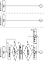
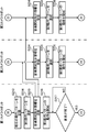
- FIG. 6 is a first flowchart for explaining the operation of the imaging system according to the first embodiment of the present disclosure
- FIG. 7 is a first flowchart for explaining the operation of the imaging system according to the first embodiment of the present disclosure. It is a flowchart of 2.
- the first camera robot 1 is the main camera robot
- the second camera robot 2 and the third camera robot 3 are the secondary camera robots.
- step S4 the control unit 13 determines whether or not one or more subjects recognized by the image recognition unit 12 are only children.
- the control unit 13 selects the first operation pattern in step S5.
- the first motion pattern is an motion pattern expressing a situation in which the first camera robot 1, the second camera robot 2, and the third camera robot 3 make noise.
- step S7 the communication unit 19 provides the second camera robot 2 and the second camera robot 2 with operation start instruction information for operating the second camera robot 2 and the third camera robot 3 according to the operation pattern selected by the control unit 13. 3 Send to camera robot 3.
- step S8 the control unit 13 starts the operation of the selected operation pattern.
- the control unit 13 outputs a control signal corresponding to the drive pattern associated with the first operation pattern to the drive unit 18, and the image associated with the first operation pattern. Is output to the display unit 16, and the sound associated with the first operation pattern is output to the speaker 15.
- the first operation pattern is associated with, for example, a drive pattern that repeats an operation of rotating the upper housing 102 at a predetermined angle in one direction and rotating the upper housing 102 at a predetermined angle in the other direction.
- an image imitating a laughing eye is associated with the first operation pattern.
- FIG. 8 is a diagram showing an example of an image displayed on the display unit when the first operation pattern is selected in the first embodiment.
- the first operation pattern is associated with, for example, music that makes children happy.
- the second operation pattern is associated with, for example, an image imitating moist eyes.
- FIG. 9 is a diagram showing an example of an image displayed on the display unit when the second operation pattern is selected in the first embodiment.
- the display unit 16 displays an image imitating moist eyes.
- the second operation pattern is associated with, for example, silent or quiet music.
- step S9 the shutter unit 17 starts outputting the captured image by the camera 11.
- the shutter unit 17 outputs a captured image from the camera 11 to the communication unit 19 every second, for example.
- the communication unit 19 transmits the captured image acquired from the camera 11 to the server 4 every second.
- the shutter unit 17 captures images while the first camera robot 1 is operating according to the selected operation pattern, that is, from the start of imaging until one or more subjects are no longer detected in the captured image. Output the image.
- step S21 the communication unit 19 of the second camera robot 2 receives the operation start instruction information transmitted by the first camera robot 1.
- the operation start instruction information includes information that identifies the operation pattern selected by the first camera robot 1.
- step S22 the control unit 13 starts the operation of the operation pattern selected by the first camera robot 1.
- the control unit 13 outputs a control signal corresponding to the drive pattern associated with the first operation pattern to the drive unit 18, and outputs the control signal to the drive unit 18, and the first operation pattern.
- the image associated with is output to the display unit 16, and the sound associated with the first operation pattern is output to the speaker 15.
- the first motion pattern of the second camera robot 2 is the same as the first motion pattern of the first camera robot 1.
- the control unit 13 when the second operation pattern is selected by the first camera robot 1, the control unit 13 outputs a control signal corresponding to the drive pattern associated with the second operation pattern to the drive unit 18, and the second operation unit 13 outputs the control signal to the drive unit 18.
- the image associated with the operation pattern is output to the display unit 16, and the sound associated with the second operation pattern is output to the speaker 15.
- the second motion pattern of the second camera robot 2 is the same as the second motion pattern of the first camera robot 1.
- step S23 the shutter unit 17 starts outputting the captured image by the camera 11.
- the shutter unit 17 outputs a captured image from the camera 11 to the communication unit 19 every second, for example.
- the communication unit 19 transmits the captured image acquired from the camera 11 to the server 4 every second.
- the shutter unit 17 is used while the second camera robot 2 is operating according to the selected operation pattern, that is, from the start of imaging until no one or more subjects are detected in the captured image (operation end instruction).
- the captured image is output until the information is received).
- step S31 the communication unit 19 of the third camera robot 3 receives the operation start instruction information transmitted by the first camera robot 1.
- steps S31 to S33 by the third camera robot 3 is the same as the processing of steps S21 to S23 by the second camera robot 2.
- the first camera robot 1, the second camera robot 2, and the third camera robot 3 create a fun and noisy situation.
- the first camera robot 1, the second camera robot 2, and the third camera robot 3 can make one or more children feel happy and bring out the good facial expressions of one or more children.
- the server 4 can acquire the captured image of one or more children's good facial expressions.
- the first camera robot 1, the second camera robot 2, and the third camera robot 3 create a quiet situation.
- the first camera robot 1, the second camera robot 2, and the third camera robot 3 can create different situations depending on whether there are only children or adults, and one or more children get bored. You can prevent it from happening.
- step S10 the image recognition unit 12 of the first camera robot 1 determines whether or not one or more subjects have been detected from the captured image.
- the process of step S10 is repeated, and the operation of the selected operation pattern and the output of the captured image are continuously performed. ..
- step S11 the communication unit 19 has the second camera robot 2 and the third camera robot according to the operation pattern.
- the operation end instruction information for terminating the operation of 3 is transmitted to the second camera robot 2 and the third camera robot 3.
- step S12 the control unit 13 ends the operation of the selected operation pattern.
- step S13 the shutter unit 17 ends the output of the captured image by the camera 11.
- step S24 the communication unit 19 of the second camera robot 2 receives the operation end instruction information transmitted by the first camera robot 1.
- step S25 the control unit 13 ends the operation of the operation pattern selected by the first camera robot 1.
- step S34 the communication unit 19 of the third camera robot 3 receives the operation end instruction information transmitted by the first camera robot 1.
- steps S34 to S36 by the third camera robot 3 is the same as the processing of steps S24 to S26 by the second camera robot 2.
- the operation pattern of the first camera robot 1 is selected based on the attributes of one or more subjects, and the first camera robot 1 and other robots (second camera robot 2 and third) are selected according to the selected operation pattern.
- One or more subjects were imaged while the camera robot 3) was operating and the first camera robot 1 and other robots (second camera robot 2 and third camera robot 3) were operating according to the selected motion pattern.
- the image is output.
- first camera robot 1, second camera robot 2 and third camera robot 3 operate simultaneously according to the selected motion pattern, it is possible to provide a space with a fun atmosphere to one or more subjects. It is possible to bring out a good facial expression of one or more subjects.
- the installation location is, for example, a table in the living room and a shelf in the living room.
- the installation location is entered by the user.
- There are three types of personality for example, "noisy”, "normal”, and “quiet”.
- the personality may be input by the user or may be preset.
- the control unit 13 determines the amount of movement in the selected movement pattern. It may be increased by 10%. Further, when there is another camera robot whose installation location is the same as that of the first camera robot 1 and whose character is incompatible with the first camera robot 1, the control unit 13 operates in the selected operation pattern. The amount may be reduced by 10%.
- the drive unit 18 may increase or decrease the angle at which the upper housing 102 is swiveled by 10%, or may increase or decrease the speed at which the upper housing 102 is swiveled by 10%. Further, the speaker 15 may increase or decrease the volume of the output sound by 10%.
- the lifting sensor 20 detects that the first camera robot 1A has been lifted.
- the lifting sensor 20 is, for example, an optical sensor and is provided on the bottom surface of the lower housing 101.
- the lifting sensor 20 detects that the first camera robot 1A has been lifted, the lifting sensor 20 outputs the first detection signal to the control unit 13A.
- the lifting sensor 20 detects that the lifted first camera robot 1A is placed.
- the lifting sensor 20 detects that the first camera robot 1A has been placed, it outputs a second detection signal to the control unit 13A.
- the control unit 13A selects an operation pattern that was operating before the first camera robot 1A was lifted.
- the control unit 13A switches from the third operation pattern to the operation pattern stored in the memory 14 before the first camera robot 1A is lifted. ..
- FIG. 11 is a first flowchart for explaining the operation of the imaging system according to the second embodiment of the present disclosure
- FIG. 12 is a first flowchart for explaining the operation of the imaging system according to the second embodiment of the present disclosure.
- 2 is a flowchart of FIG. 13
- FIG. 13 is a third flowchart for explaining the operation of the imaging system according to the second embodiment of the present disclosure
- FIG. 14 is an operation of the imaging system according to the second embodiment of the present disclosure. It is a 4th flowchart for demonstrating.
- the first camera robot 1A is the main camera robot
- the second camera robot 2A and the third camera robot 3A are the secondary camera robots.
- steps S101 to S109 is the same as the processing of steps S1 to S9 of FIGS. 6 and 7. Further, the processing of steps S131 to S133 is the same as the processing of steps S21 to S23 of FIG. Further, the processing of steps S151 to S153 is the same as the processing of steps S31 to S33 of FIG.
- step S110 the image recognition unit 12 of the first camera robot 1A determines whether or not one or more subjects have been detected from the captured image.
- the process shifts to step S121.
- the third operation pattern is associated with, for example, a drive pattern that repeats an operation of rotating the upper housing 102 at a predetermined angle in one direction and rotating the upper housing 102 at a predetermined angle in the other direction.
- the third operation pattern is associated with, for example, a buzzer sound or a crying voice.
- step S134 the communication unit 19A of the second camera robot 2A receives the lifting information transmitted by the first camera robot 1.
- the fourth operation pattern is associated with, for example, an image imitating an angry eye.
- FIG. 16 is a diagram showing an example of an image displayed on the display unit when the fourth operation pattern is selected in the second embodiment.
- the display unit 16 displays an image imitating an angry eye.
- the fourth operation pattern is associated with, for example, a buzzer sound or an angry voice.
- step S154 the communication unit 19A of the third camera robot 3A receives the lifting information transmitted by the first camera robot 1A.
- steps S154 to S156 by the third camera robot 3A is the same as the processing of steps S134 to S136 by the second camera robot 2A.
- the lifted camera robot operates in the disliked third motion pattern, and the other camera robots operate in the angry fourth motion pattern. You can be encouraged to put it down.
- step S116 the control unit 13A of the first camera robot 1A determines whether or not a predetermined time has elapsed since the first camera robot 1A was lifted.
- the process shifts to step S121.
- step S117 the control unit 13A determines whether or not the first camera robot 1A has been placed. To judge. When the lifting sensor 20 detects that the first camera robot 1A has been placed, the control unit 13A determines that the first camera robot 1A has been placed.
- step S117 if it is determined that the first camera robot 1A is not placed (NO in step S117), the process returns to step S116.
- step S118 the control unit 13A selects an operation pattern before the first camera robot 1A is lifted.
- the control unit 13A reads the operation pattern before the first camera robot 1A is lifted from the memory 14.
- step S119 the communication unit 19A transmits the mounting information indicating that the first camera robot 1A has been placed to the second camera robot 2 and the third camera robot 3.
- the mounting information includes information for specifying an operation pattern before the first camera robot 1A is lifted.
- step S120 the control unit 13A starts the operation of the operation pattern before the first camera robot 1A is lifted.
- the control unit 13A starts the operation of the first operation pattern.
- the control unit 13A starts the operation of the second operation pattern. Then, after the operation of the operation pattern before the first camera robot 1A is lifted is started, the process returns to step S110.
- step S137 the communication unit 19A of the second camera robot 2A receives the mounting information transmitted by the first camera robot 1A.
- step S157 the communication unit 19A of the third camera robot 3A receives the mounting information transmitted by the first camera robot 1A.
- steps S157 to S158 by the third camera robot 3A is the same as the processing of steps S137 to S138 by the second camera robot 2A.
- step S121 the communication unit 19A provides the operation end instruction information for terminating the operations of the second camera robot 2A and the third camera robot 3A according to the operation pattern to the second camera robot 2A. And it is transmitted to the third camera robot 3A.
- steps S121 to S123 is the same as the processing of steps S11 to S13 of FIG. Further, the processing of steps S139 to S141 is the same as the processing of steps S24 to S26 of FIG. Further, the processing of steps S159 to S161 is the same as the processing of steps S34 to S36 of FIG.
- a third motion pattern that reacts to the lift is selected, and the first camera robot 1A follows the third motion pattern.
- the first camera robot 1A follows the third motion pattern.
- the first camera robot 1A follows the third motion pattern.
- the first camera robot 1A follows the third motion pattern.
- the first camera robot 1A follows the third motion pattern.
- the first camera robot 1A follows the third motion pattern.
- the first camera robot 1A can enjoy the operation of the first camera robot 1A according to the third operation pattern different from the first operation pattern and the second operation pattern by intentionally lifting the first camera robot 1A. ..
- a fifth motion pattern expressing a situation in which a plurality of camera robots output sound from the speaker in accordance with the rhythm of music. Is selected.
- FIG. 17 is a block diagram showing the configuration of the first camera robot according to the third embodiment of the present disclosure.
- the imaging system according to the third embodiment includes a first camera robot 1B, a second camera robot 2B, a third camera robot 3B, and a server 4. Since the configurations of the second camera robot 2B and the third camera robot 3B are the same as the configurations of the first camera robot 1B, only the configuration of the first camera robot 1B will be described.
- the same components as those in the first embodiment are designated by the same reference numerals, and the description thereof will be omitted.
- the first camera robot 1B shown in FIG. 17 includes a camera 11, an image recognition unit 12, a control unit 13B, a memory 14, a speaker 15, a display unit 16, a shutter unit 17, a drive unit 18, a communication unit 19B, a sound collecting unit 21, and a sound collecting unit 21.
- a music recognition unit 22 is provided.
- the sound collecting unit 21 is, for example, a microphone, and collects ambient sounds.
- the music recognition unit 22 recognizes that the sound collected by the sound collection unit 21 is music.
- a technique for recognizing that the collected sound is music is a known technique. For example, there is a technique for identifying a song title from the collected sounds.
- the music recognition unit 22 may recognize that the collected sounds are music.
- the control unit 13B selects a fifth operation pattern that outputs sound from the speaker 15 in accordance with the rhythm of the music recognized by the music recognition unit 22.
- the communication unit 19B provides music start instruction information for operating the other camera robots (second camera robot 2B and third camera robot 3B) according to the fifth operation pattern selected by the control unit 13B (third camera robot). It is transmitted to the 2 camera robot 2B and the 3rd camera robot 3B).
- the communication unit 19B provides music start instruction information for operating the first camera robot 1B according to the fifth operation pattern selected by another camera robot (second camera robot 2B or third camera robot 3B). Received from the camera robot (second camera robot 2B or third camera robot 3B). The control unit 13B operates the first camera robot 1B according to the fifth operation pattern included in the music start instruction information received by the communication unit 19B.
- the communication unit 19B receives the music end instruction information from other camera robots (second camera robot 2B and third camera robot 3B).
- the control unit 13B receives the music end instruction information from the other camera robots (second camera robot 2B and third camera robot 3B)
- the control unit 13B receives the music end instruction information from the other camera robots (second camera robot 2B and third camera robot 3B).
- the music end instruction information includes an operation pattern in which the other camera robots (second camera robot 2B and third camera robot 3B) were operating before recognizing the music.
- steps S201 to S209 is the same as the processing of steps S1 to S9 of FIGS. 6 and 7. Further, the processing of steps S231 to S233 is the same as the processing of steps S21 to S23 of FIG. Further, the processing of steps S251 to S253 is the same as the processing of steps S31 to S33 of FIG.
- step S210 the image recognition unit 12 of the first camera robot 1B determines whether or not one or more subjects have been detected from the captured image.
- the process shifts to step S221.
- step S212 the control unit 13B determines whether or not the sound collected by the sound collecting unit 21 is music.
- the control unit 13B recognizes that the sound collected by the music recognition unit 22 is music
- the control unit 13B determines that the collected sound is music.
- Music includes songs and songs played by musical instruments. In addition, music is sung by one or more subjects, or output from a television, radio, smartphone, or the like.
- step S212 if it is determined that the collected sound is not music (NO in step S212), the process returns to step S210.
- step S213 the control unit 13B stores the current operation pattern, that is, the operation pattern before the music is recognized in the memory 14.
- step S214 the control unit 13B selects the fifth operation pattern.
- the fifth operation pattern is an operation pattern in which sound is output from the speaker 15 in accordance with the recognized rhythm of the music.
- the control unit 13B outputs the sound of a musical instrument such as a drum or a flute from the speaker 15 in synchronization with the rhythm of music.
- step S215 the communication unit 19B provides music start instruction information for operating the second camera robot 2 and the third camera robot 3 according to the fifth operation pattern selected by the control unit 13B. And the third camera robot 3.
- the fifth operation pattern is associated with, for example, a drive pattern in which the operation of rotating the upper housing 102 at a predetermined angle in one direction and rotating the upper housing 102 at a predetermined angle in the other direction is repeated in synchronization with the rhythm of music. ing. Further, the fifth operation pattern is associated with, for example, an image imitating a laughing eye shown in FIG. Further, the fifth operation pattern is associated with the sound of a musical instrument such as a drum or a flute, for example.
- step S234 the communication unit 19B of the second camera robot 2B receives the music start instruction information transmitted by the first camera robot 1.
- step S237 the communication unit 19B of the second camera robot 2B receives the music end instruction information transmitted by the first camera robot 1B.
- step S257 the communication unit 19B of the third camera robot 3B receives the music end instruction information transmitted by the first camera robot 1B.
- steps S257 to S258 by the third camera robot 3B is the same as the processing of steps S237 to S238 by the second camera robot 2B.
- step S221 the communication unit 19B has the second camera robot 2A and the second camera robot 2A according to the operation pattern. 3 The operation end instruction information for terminating the operation of the camera robot 3A is transmitted to the second camera robot 2A and the third camera robot 3A.
- the sound is output from the speaker 15 in accordance with the rhythm of the recognized music, so that a space with a fun atmosphere is provided to one or more subjects. It is possible to bring out a good facial expression of one or more subjects.
- the music recognition unit 22 may acquire a song sung by one or more subjects and specify the song title of the acquired song. Then, the control unit 13B may acquire the music corresponding to the music name specified by the music recognition unit 22 from the server 4 via the communication unit 19B, and output the acquired music from the speaker 15.
- the server 4 may include a music recognition unit 22.
- the communication unit 19B may transmit the collected sound to the server 4 and receive the recognition result by the server 4.
- drawing out a good facial expression of the subject of the camera 11 is equivalent to entertaining the people around the robot. Therefore, the functions of the first to third embodiments can be applied to the robot not equipped with the camera function.
- the first camera robot, the second camera robot, and the third camera robot may execute an operation according to the sound output from the television or the tablet computer together with the image.
- the first camera robot, the second camera robot, and the third camera robot recognize the sound collecting unit that acquires the sound output from the television or the tablet computer together with the image, and the sound acquired by the sound collecting unit.
- a sound recognition unit may be further provided.
- the sound recognition unit may recognize the content of the conversation of the person.
- the control unit may output a simple voice from the speaker 15 in the middle of the recognized conversation. For example, the control unit may output short words sandwiched between conversations as voice from the speaker 15.
- the first camera robot, the second camera robot, and the third camera robot operate in response to the video and audio output to the television or tablet computer. This makes the user's video experience more enjoyable.
- the first camera robot, the second camera robot, and the third camera robot may execute an operation according to the posted character.
- the first camera robot, the second camera robot, and the third camera robot have a communication unit that receives characters posted from the terminal to the SNS site from the terminal or the SNS site, and character recognition that recognizes the received characters.
- a unit may be further provided.
- the control unit may output the voice corresponding to the recognized character from the speaker 15.
- the control unit may output different voices from the speaker 15 according to the recognized characters.
- the first camera robot, the second camera robot, and the third camera robot may execute an operation according to the purchased product.
- the first camera robot, the second camera robot, and the third camera robot may further include a communication unit that receives information about the product purchased from the terminal on the EC site from the terminal or the EC site.
- the control unit may output the sound corresponding to the received information about the product from the speaker 15.
- the control unit may output different sounds from the speaker 15 depending on the price of the product.
- the first camera robot, the second camera robot, and the third camera robot operate in response to the user's actions on the Internet.
- the first camera robot, the second camera robot, and the third camera robot can connect the world of the Internet and the real world, and make the user's life more enjoyable.
- the first camera robot, the second camera robot, and the third camera robot may execute an operation according to a change in odor, brightness, or air quality.
- the first camera robot, the second camera robot, and the third camera robot may further include an odor sensor, a brightness sensor, or a dust sensor.
- the odor sensor detects ambient odor components.
- the control unit causes the display unit 16 to display an image showing a facial expression associated with the detected odor component in advance, and a part of the main body 100 according to the drive pattern previously associated with the detected odor component. May be driven by the drive unit 18.
- the control unit may perform different operations depending on the odor component.
- the control unit may display an image showing a happy expression on the display unit 16 with respect to the smell of supper.
- the dust sensor also detects the amount of dust in the surroundings.
- the control unit may display an image showing a facial expression associated with the detected amount of dust on the display unit 16.
- the control unit may perform different operations depending on the amount of dust.
- the first camera robot, the second camera robot, and the third camera robot may execute an operation according to a change in the operation of the home electric appliance.
- the first camera robot, the second camera robot, and the third camera robot may further include a communication unit that receives an operation completion signal indicating that a predetermined operation is completed from the home electric appliance.
- the control unit may output a predetermined sound from the speaker 15.
- the control unit may output a voice notifying that cooking is completed from the speaker 15.
- the control unit may output a voice notifying that the coffee drip is completed from the speaker 15.
- the life of the user using the home electric appliance can be made more enjoyable.
- each component may be configured by dedicated hardware or may be realized by executing a software program suitable for each component.
- Each component may be realized by a program execution unit such as a CPU or a processor reading and executing a software program recorded on a recording medium such as a hard disk or a semiconductor memory.
- each step shown in the above flowchart is executed is for exemplifying the present disclosure in detail, and may be an order other than the above as long as the same effect can be obtained. .. Further, a part of the above steps may be executed at the same time (parallel) as other steps.
Landscapes
- Engineering & Computer Science (AREA)
- Multimedia (AREA)
- Theoretical Computer Science (AREA)
- Physics & Mathematics (AREA)
- General Physics & Mathematics (AREA)
- Signal Processing (AREA)
- Human Computer Interaction (AREA)
- Health & Medical Sciences (AREA)
- General Health & Medical Sciences (AREA)
- Audiology, Speech & Language Pathology (AREA)
- General Engineering & Computer Science (AREA)
- Acoustics & Sound (AREA)
- Oral & Maxillofacial Surgery (AREA)
- Manipulator (AREA)
- Toys (AREA)
- Studio Devices (AREA)
Priority Applications (4)
| Application Number | Priority Date | Filing Date | Title |
|---|---|---|---|
| JP2021552119A JP7403552B2 (ja) | 2019-10-16 | 2020-08-19 | ロボット、制御処理方法及び制御処理プログラム |
| CN202080059815.0A CN114303365B (zh) | 2019-10-16 | 2020-08-19 | 机器人、控制处理方法以及存储介质 |
| US17/677,747 US11991437B2 (en) | 2019-10-16 | 2022-02-22 | Robot, control processing method, and non-transitory computer readable recording medium storing control processing program |
| JP2023208699A JP2024025810A (ja) | 2019-10-16 | 2023-12-11 | 制御装置、制御方法及び制御プログラム |
Applications Claiming Priority (4)
| Application Number | Priority Date | Filing Date | Title |
|---|---|---|---|
| US201962915858P | 2019-10-16 | 2019-10-16 | |
| US62/915,858 | 2019-10-16 | ||
| JP2019231304 | 2019-12-23 | ||
| JP2019-231304 | 2019-12-23 |
Related Child Applications (1)
| Application Number | Title | Priority Date | Filing Date |
|---|---|---|---|
| US17/677,747 Continuation US11991437B2 (en) | 2019-10-16 | 2022-02-22 | Robot, control processing method, and non-transitory computer readable recording medium storing control processing program |
Publications (1)
| Publication Number | Publication Date |
|---|---|
| WO2021075144A1 true WO2021075144A1 (ja) | 2021-04-22 |
Family
ID=75537802
Family Applications (1)
| Application Number | Title | Priority Date | Filing Date |
|---|---|---|---|
| PCT/JP2020/031335 Ceased WO2021075144A1 (ja) | 2019-10-16 | 2020-08-19 | ロボット、制御処理方法及び制御処理プログラム |
Country Status (4)
| Country | Link |
|---|---|
| US (1) | US11991437B2 (https=) |
| JP (2) | JP7403552B2 (https=) |
| CN (1) | CN114303365B (https=) |
| WO (1) | WO2021075144A1 (https=) |
Cited By (1)
| Publication number | Priority date | Publication date | Assignee | Title |
|---|---|---|---|---|
| WO2025158885A1 (ja) * | 2024-01-22 | 2025-07-31 | ソニーグループ株式会社 | 自律移動体、制御方法、情報処理装置、及び、情報処理方法 |
Families Citing this family (2)
| Publication number | Priority date | Publication date | Assignee | Title |
|---|---|---|---|---|
| WO2024124482A1 (zh) * | 2022-12-15 | 2024-06-20 | 北京可以科技有限公司 | 人机交互装置及人机交互方法 |
| JP7761029B2 (ja) * | 2023-09-12 | 2025-10-28 | カシオ計算機株式会社 | 撮影システム、撮影装置、撮影方法及びプログラム |
Citations (3)
| Publication number | Priority date | Publication date | Assignee | Title |
|---|---|---|---|---|
| WO2016068262A1 (ja) * | 2014-10-29 | 2016-05-06 | 京セラ株式会社 | コミュニケーションロボット |
| WO2018047900A1 (ja) * | 2016-09-09 | 2018-03-15 | Groove X株式会社 | ゲストを受け入れる自律行動型ロボット |
| JP2019150893A (ja) * | 2018-02-28 | 2019-09-12 | シャープ株式会社 | ロボット制御システム、ロボット制御方法およびロボット制御プログラム |
Family Cites Families (21)
| Publication number | Priority date | Publication date | Assignee | Title |
|---|---|---|---|---|
| JP2001334482A (ja) * | 2000-03-24 | 2001-12-04 | Sony Corp | ロボット装置及びロボット装置の行動決定方法 |
| JP2002185837A (ja) | 2000-12-18 | 2002-06-28 | Oyo Keisoku Kenkyusho:Kk | ロボットカメラ装置 |
| JP2005328461A (ja) * | 2004-05-17 | 2005-11-24 | Nippon Telegr & Teleph Corp <Ntt> | テレビ会議装置及び多地点テレビ会議システム |
| JP4923876B2 (ja) * | 2006-09-01 | 2012-04-25 | 富士通株式会社 | 情報提供ロボットおよびロボットを用いた情報提供方法 |
| KR20090103078A (ko) * | 2008-03-27 | 2009-10-01 | 인제대학교 산학협력단 | 휴대폰 합체 로봇 및 원격 제어 방법 |
| CN104410788B (zh) * | 2009-12-28 | 2019-05-10 | 株式会社尼康 | 摄像装置 |
| JP2012175487A (ja) * | 2011-02-23 | 2012-09-10 | Brother Ind Ltd | 会議端末、会議システム、会議方法、及び会議プログラム |
| JP6140579B2 (ja) * | 2012-09-05 | 2017-05-31 | 本田技研工業株式会社 | 音響処理装置、音響処理方法、及び音響処理プログラム |
| US10455148B2 (en) * | 2014-01-28 | 2019-10-22 | Sony Corporation | Image capturing device to capture image of a subject based on a communication process |
| JP2015186020A (ja) * | 2014-03-24 | 2015-10-22 | オリンパス株式会社 | 表示機器、撮影機器及び表示方法 |
| JP6432290B2 (ja) * | 2014-11-07 | 2018-12-05 | カシオ計算機株式会社 | 撮像装置、撮像制御方法、及びプログラム |
| KR101736134B1 (ko) * | 2014-11-14 | 2017-05-16 | 이창길 | 행동블록을 이용한 로봇 구동 시스템 및 그 방법 |
| US9724824B1 (en) * | 2015-07-08 | 2017-08-08 | Sprint Communications Company L.P. | Sensor use and analysis for dynamic update of interaction in a social robot |
| US20180353869A1 (en) * | 2015-12-17 | 2018-12-13 | Lyrebird Interactive Holdings Pty Ltd | Apparatus and method for an interactive entertainment media device |
| CN109153127B (zh) * | 2016-03-28 | 2022-05-31 | Groove X 株式会社 | 执行迎接行为的行为自主型机器人 |
| WO2017199662A1 (ja) * | 2016-05-20 | 2017-11-23 | Groove X株式会社 | 自律行動型ロボット及びコンピュータプログラム |
| CN106131393A (zh) * | 2016-06-15 | 2016-11-16 | 北京小米移动软件有限公司 | 拍照提示方法及装置 |
| DE102016221578B3 (de) * | 2016-11-03 | 2018-03-29 | Sivantos Pte. Ltd. | Verfahren zur Takterkennung mittels eines Hörgerätes |
| CN110024369A (zh) * | 2016-11-30 | 2019-07-16 | 华为技术有限公司 | 一种拍照方法、装置及终端设备 |
| JP2019125095A (ja) * | 2018-01-15 | 2019-07-25 | シャープ株式会社 | ロボット、人物検知システム、制御装置、制御プログラムおよび制御装置の制御方法 |
| JP7109207B2 (ja) * | 2018-02-23 | 2022-07-29 | パナソニックホールディングス株式会社 | 相互作用装置、相互作用方法、相互作用プログラム及びロボット |
-
2020
- 2020-08-19 JP JP2021552119A patent/JP7403552B2/ja active Active
- 2020-08-19 WO PCT/JP2020/031335 patent/WO2021075144A1/ja not_active Ceased
- 2020-08-19 CN CN202080059815.0A patent/CN114303365B/zh active Active
-
2022
- 2022-02-22 US US17/677,747 patent/US11991437B2/en active Active
-
2023
- 2023-12-11 JP JP2023208699A patent/JP2024025810A/ja active Pending
Patent Citations (3)
| Publication number | Priority date | Publication date | Assignee | Title |
|---|---|---|---|---|
| WO2016068262A1 (ja) * | 2014-10-29 | 2016-05-06 | 京セラ株式会社 | コミュニケーションロボット |
| WO2018047900A1 (ja) * | 2016-09-09 | 2018-03-15 | Groove X株式会社 | ゲストを受け入れる自律行動型ロボット |
| JP2019150893A (ja) * | 2018-02-28 | 2019-09-12 | シャープ株式会社 | ロボット制御システム、ロボット制御方法およびロボット制御プログラム |
Cited By (1)
| Publication number | Priority date | Publication date | Assignee | Title |
|---|---|---|---|---|
| WO2025158885A1 (ja) * | 2024-01-22 | 2025-07-31 | ソニーグループ株式会社 | 自律移動体、制御方法、情報処理装置、及び、情報処理方法 |
Also Published As
| Publication number | Publication date |
|---|---|
| JP7403552B2 (ja) | 2023-12-22 |
| CN114303365B (zh) | 2024-07-26 |
| CN114303365A (zh) | 2022-04-08 |
| US20220182533A1 (en) | 2022-06-09 |
| US11991437B2 (en) | 2024-05-21 |
| JPWO2021075144A1 (https=) | 2021-04-22 |
| JP2024025810A (ja) | 2024-02-26 |
Similar Documents
| Publication | Publication Date | Title |
|---|---|---|
| JP2024025810A (ja) | 制御装置、制御方法及び制御プログラム | |
| KR102655147B1 (ko) | 상호작용 애니메이션 캐릭터 헤드 시스템 및 방법 | |
| KR102334942B1 (ko) | 돌봄 로봇을 위한 데이터 처리 방법 및 장치 | |
| JP5339900B2 (ja) | コンピューターインタラクティブ処理による選択的音源聴取 | |
| CN102707797B (zh) | 通过自然用户界面控制多媒体系统中的电子设备 | |
| CN205750721U (zh) | 信息处理装置 | |
| CN112203732A (zh) | 识别玩家参与度以生成情景游戏玩法辅助 | |
| US20130150136A1 (en) | Electronic circle game system | |
| WO2017130486A1 (ja) | 情報処理装置、情報処理方法およびプログラム | |
| CN109635616A (zh) | 互动方法和设备 | |
| CN105141587A (zh) | 一种虚拟玩偶互动方法及装置 | |
| CN104800950A (zh) | 自闭症儿童辅助机器人及系统 | |
| US20180027090A1 (en) | Information processing device, information processing method, and program | |
| CN109119080A (zh) | 声音识别方法、装置、穿戴式设备及存储介质 | |
| JP2021039677A (ja) | 情報処理方法、プログラム及び情報処理装置 | |
| CN204637246U (zh) | 自闭症儿童辅助机器人及系统 | |
| CN117859147A (zh) | 信息处理装置、信息处理方法和程序 | |
| CN101360304A (zh) | 移动终端娱乐方法及相应的移动终端 | |
| JP2021096272A (ja) | 情報処理装置、情報処理方法、及びプログラム | |
| JP2018186326A (ja) | ロボット装置及びプログラム | |
| EP4735983A1 (en) | User interfaces and techniques for responding to notifications | |
| CN112508161A (zh) | 陪伴数字替身的控制方法、系统和存储介质 | |
| WO2024169957A1 (zh) | 一种心跳模拟方法、装置、移动设备及存储介质 | |
| CN109151515A (zh) | 表演场景下的互动系统和方法 | |
| JP2019170544A (ja) | 動作装置、動作玩具及びシステム |
Legal Events
| Date | Code | Title | Description |
|---|---|---|---|
| 121 | Ep: the epo has been informed by wipo that ep was designated in this application |
Ref document number: 20877626 Country of ref document: EP Kind code of ref document: A1 |
|
| ENP | Entry into the national phase |
Ref document number: 2021552119 Country of ref document: JP Kind code of ref document: A |
|
| NENP | Non-entry into the national phase |
Ref country code: DE |
|
| 32PN | Ep: public notification in the ep bulletin as address of the adressee cannot be established |
Free format text: NOTING OF LOSS OF RIGHTS PURSUANT TO RULE 112(1) EPC (EPO FORM 1205A DATED 19/08/2022) |
|
| 122 | Ep: pct application non-entry in european phase |
Ref document number: 20877626 Country of ref document: EP Kind code of ref document: A1 |