WO2021075140A1 - Dispositif électroluminescent et système électroluminescent - Google Patents
Dispositif électroluminescent et système électroluminescent Download PDFInfo
- Publication number
- WO2021075140A1 WO2021075140A1 PCT/JP2020/030964 JP2020030964W WO2021075140A1 WO 2021075140 A1 WO2021075140 A1 WO 2021075140A1 JP 2020030964 W JP2020030964 W JP 2020030964W WO 2021075140 A1 WO2021075140 A1 WO 2021075140A1
- Authority
- WO
- WIPO (PCT)
- Prior art keywords
- holding member
- light irradiation
- irradiation device
- optical fiber
- tip
- Prior art date
Links
- 239000013307 optical fiber Substances 0.000 claims abstract description 154
- 229920005989 resin Polymers 0.000 claims description 61
- 239000011347 resin Substances 0.000 claims description 61
- 230000002093 peripheral effect Effects 0.000 claims description 55
- 239000011247 coating layer Substances 0.000 claims description 5
- 239000003550 marker Substances 0.000 description 31
- 239000000463 material Substances 0.000 description 15
- 230000000694 effects Effects 0.000 description 14
- 206010028980 Neoplasm Diseases 0.000 description 12
- 238000010586 diagram Methods 0.000 description 12
- 238000000034 method Methods 0.000 description 12
- 238000002428 photodynamic therapy Methods 0.000 description 11
- 201000011510 cancer Diseases 0.000 description 10
- 239000000126 substance Substances 0.000 description 9
- 210000004027 cell Anatomy 0.000 description 8
- 238000012986 modification Methods 0.000 description 7
- 230000004048 modification Effects 0.000 description 7
- 238000011282 treatment Methods 0.000 description 7
- 230000001678 irradiating effect Effects 0.000 description 6
- 229920000642 polymer Polymers 0.000 description 5
- 230000005540 biological transmission Effects 0.000 description 4
- 210000004907 gland Anatomy 0.000 description 4
- 239000007769 metal material Substances 0.000 description 4
- 230000003014 reinforcing effect Effects 0.000 description 4
- 210000001519 tissue Anatomy 0.000 description 4
- XUIMIQQOPSSXEZ-UHFFFAOYSA-N Silicon Chemical compound [Si] XUIMIQQOPSSXEZ-UHFFFAOYSA-N 0.000 description 3
- 230000003287 optical effect Effects 0.000 description 3
- -1 polyethylene terephthalate Polymers 0.000 description 3
- 238000012545 processing Methods 0.000 description 3
- 230000005855 radiation Effects 0.000 description 3
- 239000010703 silicon Substances 0.000 description 3
- 229910052710 silicon Inorganic materials 0.000 description 3
- WFKWXMTUELFFGS-UHFFFAOYSA-N tungsten Chemical compound [W] WFKWXMTUELFFGS-UHFFFAOYSA-N 0.000 description 3
- 229910052721 tungsten Inorganic materials 0.000 description 3
- 239000010937 tungsten Substances 0.000 description 3
- YCKRFDGAMUMZLT-UHFFFAOYSA-N Fluorine atom Chemical compound [F] YCKRFDGAMUMZLT-UHFFFAOYSA-N 0.000 description 2
- VYPSYNLAJGMNEJ-UHFFFAOYSA-N Silicium dioxide Chemical compound O=[Si]=O VYPSYNLAJGMNEJ-UHFFFAOYSA-N 0.000 description 2
- 238000009825 accumulation Methods 0.000 description 2
- 230000002785 anti-thrombosis Effects 0.000 description 2
- TZCXTZWJZNENPQ-UHFFFAOYSA-L barium sulfate Chemical compound [Ba+2].[O-]S([O-])(=O)=O TZCXTZWJZNENPQ-UHFFFAOYSA-L 0.000 description 2
- 210000003445 biliary tract Anatomy 0.000 description 2
- 230000017531 blood circulation Effects 0.000 description 2
- 210000004204 blood vessel Anatomy 0.000 description 2
- 210000002249 digestive system Anatomy 0.000 description 2
- 239000011737 fluorine Substances 0.000 description 2
- 229910052731 fluorine Inorganic materials 0.000 description 2
- 239000010410 layer Substances 0.000 description 2
- 210000002751 lymph Anatomy 0.000 description 2
- 238000004519 manufacturing process Methods 0.000 description 2
- 210000000056 organ Anatomy 0.000 description 2
- 239000013308 plastic optical fiber Substances 0.000 description 2
- BASFCYQUMIYNBI-UHFFFAOYSA-N platinum Chemical compound [Pt] BASFCYQUMIYNBI-UHFFFAOYSA-N 0.000 description 2
- 229920003229 poly(methyl methacrylate) Polymers 0.000 description 2
- 229920006122 polyamide resin Polymers 0.000 description 2
- 239000004417 polycarbonate Substances 0.000 description 2
- 229920000515 polycarbonate Polymers 0.000 description 2
- 229920001225 polyester resin Polymers 0.000 description 2
- 239000004645 polyester resin Substances 0.000 description 2
- 239000004926 polymethyl methacrylate Substances 0.000 description 2
- 229920005672 polyolefin resin Polymers 0.000 description 2
- 229920005749 polyurethane resin Polymers 0.000 description 2
- 239000000843 powder Substances 0.000 description 2
- 230000001850 reproductive effect Effects 0.000 description 2
- 230000003248 secreting effect Effects 0.000 description 2
- 210000001635 urinary tract Anatomy 0.000 description 2
- 230000002792 vascular Effects 0.000 description 2
- 229920000178 Acrylic resin Polymers 0.000 description 1
- 239000004925 Acrylic resin Substances 0.000 description 1
- HTTJABKRGRZYRN-UHFFFAOYSA-N Heparin Chemical compound OC1C(NC(=O)C)C(O)OC(COS(O)(=O)=O)C1OC1C(OS(O)(=O)=O)C(O)C(OC2C(C(OS(O)(=O)=O)C(OC3C(C(O)C(O)C(O3)C(O)=O)OS(O)(=O)=O)C(CO)O2)NS(O)(=O)=O)C(C(O)=O)O1 HTTJABKRGRZYRN-UHFFFAOYSA-N 0.000 description 1
- 229910000990 Ni alloy Inorganic materials 0.000 description 1
- 229920001609 Poly(3,4-ethylenedioxythiophene) Polymers 0.000 description 1
- 229930182556 Polyacetal Natural products 0.000 description 1
- 239000004952 Polyamide Substances 0.000 description 1
- 239000004695 Polyether sulfone Substances 0.000 description 1
- 239000004743 Polypropylene Substances 0.000 description 1
- 239000004793 Polystyrene Substances 0.000 description 1
- 229910000831 Steel Inorganic materials 0.000 description 1
- 208000007536 Thrombosis Diseases 0.000 description 1
- WAIPAZQMEIHHTJ-UHFFFAOYSA-N [Cr].[Co] Chemical class [Cr].[Co] WAIPAZQMEIHHTJ-UHFFFAOYSA-N 0.000 description 1
- NIXOWILDQLNWCW-UHFFFAOYSA-N acrylic acid group Chemical group C(C=C)(=O)O NIXOWILDQLNWCW-UHFFFAOYSA-N 0.000 description 1
- 229910045601 alloy Inorganic materials 0.000 description 1
- 239000000956 alloy Substances 0.000 description 1
- 230000001093 anti-cancer Effects 0.000 description 1
- 239000003146 anticoagulant agent Substances 0.000 description 1
- 239000000427 antigen Substances 0.000 description 1
- 102000036639 antigens Human genes 0.000 description 1
- 108091007433 antigens Proteins 0.000 description 1
- QVGXLLKOCUKJST-UHFFFAOYSA-N atomic oxygen Chemical compound [O] QVGXLLKOCUKJST-UHFFFAOYSA-N 0.000 description 1
- WMWLMWRWZQELOS-UHFFFAOYSA-N bismuth(III) oxide Inorganic materials O=[Bi]O[Bi]=O WMWLMWRWZQELOS-UHFFFAOYSA-N 0.000 description 1
- 239000007767 bonding agent Substances 0.000 description 1
- 150000001875 compounds Chemical class 0.000 description 1
- 238000005520 cutting process Methods 0.000 description 1
- 238000013461 design Methods 0.000 description 1
- 238000011161 development Methods 0.000 description 1
- 238000009826 distribution Methods 0.000 description 1
- 239000003814 drug Substances 0.000 description 1
- 229940079593 drug Drugs 0.000 description 1
- 229920006332 epoxy adhesive Polymers 0.000 description 1
- 239000003822 epoxy resin Substances 0.000 description 1
- 230000005284 excitation Effects 0.000 description 1
- 239000011521 glass Substances 0.000 description 1
- PCHJSUWPFVWCPO-UHFFFAOYSA-N gold Chemical compound [Au] PCHJSUWPFVWCPO-UHFFFAOYSA-N 0.000 description 1
- 239000010931 gold Substances 0.000 description 1
- 229910052737 gold Inorganic materials 0.000 description 1
- 229960002897 heparin Drugs 0.000 description 1
- 229920000669 heparin Polymers 0.000 description 1
- 230000002209 hydrophobic effect Effects 0.000 description 1
- 210000000987 immune system Anatomy 0.000 description 1
- 239000000696 magnetic material Substances 0.000 description 1
- 230000014759 maintenance of location Effects 0.000 description 1
- PCLURTMBFDTLSK-UHFFFAOYSA-N nickel platinum Chemical compound [Ni].[Pt] PCLURTMBFDTLSK-UHFFFAOYSA-N 0.000 description 1
- 229910001000 nickel titanium Inorganic materials 0.000 description 1
- JFNLZVQOOSMTJK-KNVOCYPGSA-N norbornene Chemical compound C1[C@@H]2CC[C@H]1C=C2 JFNLZVQOOSMTJK-KNVOCYPGSA-N 0.000 description 1
- 229910052760 oxygen Inorganic materials 0.000 description 1
- 239000001301 oxygen Substances 0.000 description 1
- 230000035699 permeability Effects 0.000 description 1
- 229910052697 platinum Inorganic materials 0.000 description 1
- 229920002647 polyamide Polymers 0.000 description 1
- 229920000647 polyepoxide Polymers 0.000 description 1
- 229920006393 polyether sulfone Polymers 0.000 description 1
- 229920000139 polyethylene terephthalate Polymers 0.000 description 1
- 239000005020 polyethylene terephthalate Substances 0.000 description 1
- 229920006324 polyoxymethylene Polymers 0.000 description 1
- 229920001155 polypropylene Polymers 0.000 description 1
- 229920002223 polystyrene Polymers 0.000 description 1
- 229920002635 polyurethane Polymers 0.000 description 1
- 239000004814 polyurethane Substances 0.000 description 1
- 229920003225 polyurethane elastomer Polymers 0.000 description 1
- 229920000915 polyvinyl chloride Polymers 0.000 description 1
- 239000004800 polyvinyl chloride Substances 0.000 description 1
- 239000010453 quartz Substances 0.000 description 1
- 238000011160 research Methods 0.000 description 1
- 230000000717 retained effect Effects 0.000 description 1
- 238000005488 sandblasting Methods 0.000 description 1
- 239000010935 stainless steel Substances 0.000 description 1
- 229910001220 stainless steel Inorganic materials 0.000 description 1
- 239000010959 steel Substances 0.000 description 1
- 230000001225 therapeutic effect Effects 0.000 description 1
- 239000010409 thin film Substances 0.000 description 1
- 239000011800 void material Substances 0.000 description 1
Images


Classifications
-
- G—PHYSICS
- G02—OPTICS
- G02B—OPTICAL ELEMENTS, SYSTEMS OR APPARATUS
- G02B6/00—Light guides; Structural details of arrangements comprising light guides and other optical elements, e.g. couplings
- G02B6/24—Coupling light guides
- G02B6/36—Mechanical coupling means
- G02B6/3616—Holders, macro size fixtures for mechanically holding or positioning fibres, e.g. on an optical bench
- G02B6/3624—Fibre head, e.g. fibre probe termination
-
- A—HUMAN NECESSITIES
- A61—MEDICAL OR VETERINARY SCIENCE; HYGIENE
- A61N—ELECTROTHERAPY; MAGNETOTHERAPY; RADIATION THERAPY; ULTRASOUND THERAPY
- A61N5/00—Radiation therapy
- A61N5/06—Radiation therapy using light
- A61N5/0613—Apparatus adapted for a specific treatment
- A61N5/062—Photodynamic therapy, i.e. excitation of an agent
-
- A—HUMAN NECESSITIES
- A61—MEDICAL OR VETERINARY SCIENCE; HYGIENE
- A61B—DIAGNOSIS; SURGERY; IDENTIFICATION
- A61B18/00—Surgical instruments, devices or methods for transferring non-mechanical forms of energy to or from the body
- A61B18/18—Surgical instruments, devices or methods for transferring non-mechanical forms of energy to or from the body by applying electromagnetic radiation, e.g. microwaves
- A61B18/20—Surgical instruments, devices or methods for transferring non-mechanical forms of energy to or from the body by applying electromagnetic radiation, e.g. microwaves using laser
- A61B18/22—Surgical instruments, devices or methods for transferring non-mechanical forms of energy to or from the body by applying electromagnetic radiation, e.g. microwaves using laser the beam being directed along or through a flexible conduit, e.g. an optical fibre; Couplings or hand-pieces therefor
- A61B18/24—Surgical instruments, devices or methods for transferring non-mechanical forms of energy to or from the body by applying electromagnetic radiation, e.g. microwaves using laser the beam being directed along or through a flexible conduit, e.g. an optical fibre; Couplings or hand-pieces therefor with a catheter
-
- A—HUMAN NECESSITIES
- A61—MEDICAL OR VETERINARY SCIENCE; HYGIENE
- A61N—ELECTROTHERAPY; MAGNETOTHERAPY; RADIATION THERAPY; ULTRASOUND THERAPY
- A61N5/00—Radiation therapy
- A61N5/06—Radiation therapy using light
- A61N5/0601—Apparatus for use inside the body
-
- G—PHYSICS
- G02—OPTICS
- G02B—OPTICAL ELEMENTS, SYSTEMS OR APPARATUS
- G02B23/00—Telescopes, e.g. binoculars; Periscopes; Instruments for viewing the inside of hollow bodies; Viewfinders; Optical aiming or sighting devices
- G02B23/24—Instruments or systems for viewing the inside of hollow bodies, e.g. fibrescopes
- G02B23/2407—Optical details
- G02B23/2461—Illumination
- G02B23/2469—Illumination using optical fibres
-
- A—HUMAN NECESSITIES
- A61—MEDICAL OR VETERINARY SCIENCE; HYGIENE
- A61N—ELECTROTHERAPY; MAGNETOTHERAPY; RADIATION THERAPY; ULTRASOUND THERAPY
- A61N5/00—Radiation therapy
- A61N5/06—Radiation therapy using light
- A61N5/0601—Apparatus for use inside the body
- A61N2005/0602—Apparatus for use inside the body for treatment of blood vessels
-
- A—HUMAN NECESSITIES
- A61—MEDICAL OR VETERINARY SCIENCE; HYGIENE
- A61N—ELECTROTHERAPY; MAGNETOTHERAPY; RADIATION THERAPY; ULTRASOUND THERAPY
- A61N5/00—Radiation therapy
- A61N5/06—Radiation therapy using light
- A61N2005/063—Radiation therapy using light comprising light transmitting means, e.g. optical fibres
-
- A—HUMAN NECESSITIES
- A61—MEDICAL OR VETERINARY SCIENCE; HYGIENE
- A61N—ELECTROTHERAPY; MAGNETOTHERAPY; RADIATION THERAPY; ULTRASOUND THERAPY
- A61N5/00—Radiation therapy
- A61N5/06—Radiation therapy using light
- A61N2005/0632—Constructional aspects of the apparatus
-
- A—HUMAN NECESSITIES
- A61—MEDICAL OR VETERINARY SCIENCE; HYGIENE
- A61N—ELECTROTHERAPY; MAGNETOTHERAPY; RADIATION THERAPY; ULTRASOUND THERAPY
- A61N5/00—Radiation therapy
- A61N5/06—Radiation therapy using light
- A61N2005/0658—Radiation therapy using light characterised by the wavelength of light used
- A61N2005/0659—Radiation therapy using light characterised by the wavelength of light used infrared
-
- A—HUMAN NECESSITIES
- A61—MEDICAL OR VETERINARY SCIENCE; HYGIENE
- A61N—ELECTROTHERAPY; MAGNETOTHERAPY; RADIATION THERAPY; ULTRASOUND THERAPY
- A61N5/00—Radiation therapy
- A61N5/06—Radiation therapy using light
- A61N5/067—Radiation therapy using light using laser light
-
- G—PHYSICS
- G02—OPTICS
- G02B—OPTICAL ELEMENTS, SYSTEMS OR APPARATUS
- G02B6/00—Light guides; Structural details of arrangements comprising light guides and other optical elements, e.g. couplings
- G02B6/0001—Light guides; Structural details of arrangements comprising light guides and other optical elements, e.g. couplings specially adapted for lighting devices or systems
- G02B6/0005—Light guides; Structural details of arrangements comprising light guides and other optical elements, e.g. couplings specially adapted for lighting devices or systems the light guides being of the fibre type
- G02B6/0008—Light guides; Structural details of arrangements comprising light guides and other optical elements, e.g. couplings specially adapted for lighting devices or systems the light guides being of the fibre type the light being emitted at the end of the fibre
Definitions
- the present invention relates to a light irradiation device and a light irradiation system.
- PDT Photodynamic Therapy
- a light-sensitive substance is intravenously administered and then irradiated with light to generate active oxygen in cancer cells and kill the cancer cells (see, for example, Non-Patent Document 1).
- PDT has low selectivity for accumulation of light-sensitive substances in cancer cells, and the magnitude of side effects due to its uptake into normal cells becomes an issue, and PDT is not widely used as a therapeutic technique.
- NIR-PIT Near-infrared photoimmunotherapy
- a complex in which two compounds of an antibody against a specific antigen of cancer cells and a photosensitive substance (for example, IRDye700DX) are bound is used.
- this complex selectively accumulates in cancer cells in the body.
- an excitation wavelength for example, 690 nm
- the complex is activated and exhibits an anticancer effect (see, for example, Patent Document 1).
- NIR-PIT performs light irradiation (NIR irradiation) in a near-infrared region of, for example, 690 nm, the effect of NIR irradiation on the immune system can be expected (see, for example, Non-Patent Document 2).
- the predetermined wavelength region including 690 nm exemplified above is also called a spectroscopic window of a living body, and although it is a wavelength region in which light is absorbed less by biological components than other wavelength regions, light irradiation from the body surface is performed.
- a spectroscopic window of a living body although it is a wavelength region in which light is absorbed less by biological components than other wavelength regions, light irradiation from the body surface is performed.
- NIR-PIT in which light irradiation is performed at a position closer to cancer cells instead of light irradiation from the body surface (see, for example, Non-Patent Document 3).
- Patent Documents 2 to 4 disclose devices that can be used in such PDTs and NIR-PITs.
- Patent Documents 2 to 4 All of the devices described in Patent Documents 2 to 4 are used by being inserted into a living lumen such as a blood vessel, and can irradiate a deep part of the body with light transmitted by an optical fiber.
- the device described in Patent Document 5 uses laser light to form a wound in a body tissue.
- the optical fiber generally transmits light by total reflection of light utilizing the difference in refractive index between the core and the clad that covers the outer peripheral surface of the core, and emits light from the core exposed at the tip.
- the light irradiation direction is the direction of the tissue surrounding the living lumen, that is, the direction intersecting the long axis direction of the device. Is preferable.
- the devices described in Patent Documents 4 and 5 are provided with a guide means (guide member), and by moving the optical fiber using the guide means, the tip of the optical fiber is moved in the long axis direction of the device. Can be turned in the direction of intersection with.
- Patent Documents 4 and 5 have a problem that the structure of the device becomes complicated and the diameter of the device becomes large. Further, in the devices described in Patent Documents 2 and 3, no consideration is given to irradiating light in a direction intersecting the long axis direction of the device.
- such a problem is not limited to PDT and NIR-PIT, but is common to all devices used in examinations or treatments including the process of irradiating light in the body. Moreover, such a problem is not limited to the device inserted into the blood vessel, but also in the biological lumen such as the vascular system, the lymph gland system, the biliary system, the urinary tract system, the airway system, the digestive system, the secretory gland and the reproductive organ. Common to all devices inserted in.
- the present invention has been made to solve at least a part of the above-mentioned problems, and in a device capable of irradiating light from an optical fiber in a direction intersecting the long axis direction of the device, the diameter of the device is reduced.
- the purpose is.
- the present invention has been made to solve at least a part of the above-mentioned problems, and can be realized as the following forms.
- a light irradiation device having a long outer shape is provided.
- This light irradiation device is an optical fiber that irradiates light from the tip, and has a curved portion, and the curved portion is directed to a direction in which the tip intersects the long axis direction of the light irradiation device.
- a light-transmitting holding member that holds the shape of the curved portion of the optical fiber, and the optical fiber has a core or a core and one or more coating layers, and the holding member
- the refractive index of is smaller than the refractive index of the members constituting the outer surface of the optical fiber.
- the shape of the curved portion is held by the holding member in a state where the tip of the optical fiber is directed by the curved portion in the direction intersecting the long axis direction of the light irradiation device. Therefore, by moving the optical fiber using the guide means, the configuration of the light irradiation device can be simplified as compared with the configuration in which the tip of the optical fiber is directed in the direction intersecting the long axis direction of the light irradiation device. Therefore, the diameter of the light irradiation device can be reduced. Further, the refractive index of the holding member is smaller than the refractive index of the members constituting the outer surface of the optical fiber.
- a holding member having a refractive index equal to that of the member constituting the outer surface of the optical fiber or a refractive index higher than the refractive index of the member constituting the outer surface of the optical fiber is used to form the curved portion.
- the light inside the optical fiber can be reflected at the boundary between the member constituting the outer surface of the optical fiber and the holding member, as compared with the case where the shape of the optical fiber is maintained.
- the light irradiation device of this configuration the light leaking from the inside of the optical fiber can be reduced.
- the holding member may be arranged at least adjacent to the inner peripheral side of the curved portion.
- the shape of the curved portion of the optical fiber can be maintained at least from the inner peripheral side of the curved portion.
- the inner peripheral side of the curved portion is the direction in which the tip of the optical fiber is facing, that is, the direction in which light is emitted from the optical fiber.
- the substance forming the holding member has a higher refractive index than air.
- the holding member on the outer peripheral side of the curved portion (the direction in which the light is not irradiated from the optical fiber) and leaving it as a gap, the leakage of light in the direction in which the light is not irradiated from the optical fiber can be further suppressed. ..
- the holding member includes an inner holding member arranged adjacent to the inner peripheral side of the curved portion and an outer holding member arranged adjacent to the outer peripheral side of the curved portion.
- the refractive index of the outer holding member, including the member may be smaller than the refractive index of the inner holding member. According to this configuration, the shape of the curved portion can be firmly held from different directions on the inner peripheral side of the curved portion and the outer peripheral side of the curved portion. Further, the refractive index of the outer holding member arranged on the outer peripheral side of the curved portion is smaller than the refractive index of the inner holding member arranged on the inner peripheral side of the curved portion.
- the leakage of light from the outer holding member provided in the direction in which light is not emitted from the optical fiber is compared with the leakage of light from the inner holding member provided in the direction in which light is emitted from the optical fiber. It can be further suppressed.
- the inner holding member includes a first inner holding member arranged on the tip end side and a second inner holding member arranged on the proximal end side, and the second inner holding member is included.
- the refractive index of the inner holding member may be smaller than the refractive index of the first inner holding member and larger than the refractive index of the outer holding member. According to this configuration, since the inner holding member includes the first inner holding member arranged on the tip end side and the second inner holding member arranged on the proximal end side, the first and second inner holding members are included. By controlling the refractive index of the holding member, the degree of light leakage can be changed.
- the refractive index of the second inner holding member is smaller than the refractive index of the first inner holding member and larger than the refractive index of the outer holding member. Therefore, the leakage of light from the outer holding member provided in the direction in which the light is not emitted from the optical fiber is caused by the light leaking from the first and second inner holding members provided in the direction in which the light is irradiated from the optical fiber. Compared to leakage, it can be further suppressed. Further, the leakage of light from the second inner holding member arranged on the proximal end side can be further suppressed as compared with the leakage of light from the first inner holding member arranged on the distal end side.
- the light irradiation device of the above embodiment further includes a hollow shaft in which the optical fiber and the holding member are housed, and the inside of the hollow shaft is located on the proximal end side of the holding member.
- a resin member having a refractive index smaller than that of the holding member may be filled. According to this configuration, since the resin member is filled in the base end side of the inside of the hollow shaft with respect to the holding member, the long shape of the light irradiation device can be maintained. Further, since the refractive index of the resin member is smaller than the refractive index of the holding member, the light leaking through the resin member can be reduced.
- a part of the curved portion on the tip end side protrudes from the tip of the hollow shaft, and the holding member covers the periphery of the curved portion protruding from the hollow shaft.
- the light irradiation device of the above embodiment further includes a hollow shaft in which the optical fiber and the holding member are housed, and a part of the curved portion on the tip end side projects from the tip of the hollow shaft.
- the holding member may cover the periphery of the curved portion protruding from the hollow shaft, have an outer diameter substantially the same as that of the hollow shaft, and may be joined to the tip of the hollow shaft. According to this configuration, by projecting a part of the curved portion on the tip end side, that is, the tip of the optical fiber from the tip of the hollow shaft, it is possible to prevent the light emitted from the tip of the optical fiber from being blocked by the hollow shaft. Further, since the holding member covers the periphery of the protruding curved portion, the periphery of the protruding curved portion can be protected.
- a light irradiation system includes a light irradiation device of the above-described embodiment and a long tube-shaped catheter into which the light irradiation device is inserted, and the catheter is used when the light irradiation device is inserted into the catheter.
- a light transmitting portion for transmitting internal light to the outside is provided at a position corresponding to the tip of the optical fiber.
- the light irradiation system individually includes a light irradiation device and a catheter having a light transmitting portion for transmitting internal light to the outside at a position corresponding to the tip of the optical fiber. The degree of freedom can be improved and the range of procedures can be expanded.
- the present invention can be realized in various aspects, for example, a catheter, a light irradiation device, a light irradiation system in which these are separate or integrated, a catheter, a light irradiation device, and a light irradiation system. It can be realized in the form of a manufacturing method or the like.
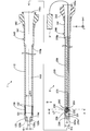
- FIG. 1 is an explanatory diagram illustrating the configuration of the light irradiation system of the first embodiment.
- the light irradiation system is used by inserting it into a biological lumen such as a vascular system, a lymph gland system, a biliary system, a urinary tract system, an airway system, a digestive system, a secretory gland and a reproductive organ.
- the light irradiation system is a system that irradiates light transmitted from the lumen of a living body toward a living tissue through an optical fiber.
- the light irradiation system can be used in, for example, PDT (Photodynamic Therapy) and NIR-PIT (Near-infrared photoimmunotherapy).
- the light irradiation system includes a catheter 1 and a light irradiation device 2 that is inserted into and used in the catheter 1. In FIG. 1, the catheter 1 and the light irradiation device 2 are shown separately.
- FIG. 1 the axis passing through the center of the catheter 1 and the axis passing through the center of the light irradiation device 2 are represented by axis lines O (dashed-dotted line), respectively.
- axis lines O dashed-dotted line
- FIG. 1 shows XYZ axes that are orthogonal to each other.
- the X-axis corresponds to the long axis direction (axis O direction) of the catheter 1 and the light irradiation device 2
- the Y-axis corresponds to the height direction of the catheter 1 and the light irradiation device 2
- the Z-axis corresponds to the catheter 1 and the light irradiation device.
- the left side (-X-axis direction) of FIG. 1 is referred to as the catheter 1, the light irradiation device 2, and the "tip side" of each component
- the right side (+ X-axis direction) of FIG. 1 is referred to as the catheter 1, the light irradiation device 2.
- the "base end side" of each component is referred to as the catheter 1 and the light irradiation device 2.
- the end portion located on the distal end side is referred to as a "tip”, and the distal end and its vicinity are referred to as a "tip portion”.
- the end portion located on the proximal end side is referred to as a "base end”, and the proximal end and its vicinity are referred to as a "base end portion”.
- the distal end side corresponds to the "distal side” inserted into the living body, and the proximal end side corresponds to the "proximal side” operated by a surgeon such as a doctor.
- the catheter 1 has a long tube shape and includes a shaft 110, a tip tip 120, and a connector 140.
- the shaft 110 is an elongated member extending along the axis O.
- the shaft 110 has a hollow substantially cylindrical shape (tube shape) in which both ends of the tip portion 110d and the base end portion 110p are open.
- the shaft 110 has a lumen 110L inside.
- the lumen 110L functions as a guide wire lumen for inserting the guide wire through the catheter 1 at the time of delivery of the catheter 1.
- the lumen 110L functions as a device lumen for inserting the light irradiation device 2 through the catheter 1 after the delivery of the catheter 1. In this way, the diameter of the catheter 1 can be reduced by using both the guide wire lumen and the device lumen as a single lumen.
- the outer diameter, inner diameter and length of the shaft 110 can be arbitrarily determined.
- the tip tip 120 is a member that is joined to the tip of the shaft 110 and advances in the lumen of the living body ahead of other members. As shown in FIG. 1, the tip tip 120 has an outer shape whose diameter is reduced from the proximal end side to the distal end side in order to facilitate the progress of the catheter 1 in the living lumen.
- a through hole 120h is formed in a substantially central portion of the tip tip 120 so as to penetrate the tip tip 120 in the O-axis direction.
- the opening diameter ⁇ 1 of the through hole 120h is smaller than the inner diameter ⁇ 2 of the lumen 110L of the shaft 110. Therefore, as shown in FIG.
- a step is formed due to the inner surface 120i of the tip tip 120 protruding.
- the opening 120o of the tip tip 120 communicates with the through hole 120h and is used when inserting a guide wire (not shown) into the catheter 1.
- the outer diameter and length of the tip tip 120 can be arbitrarily determined.
- the connector 140 is a member that is arranged on the proximal end side of the catheter 1 and is gripped by the operator.
- the connector 140 includes a substantially cylindrical connecting portion 141 and a pair of blades 142.
- the base end portion 110p of the shaft 110 is joined to the tip end portion of the connecting portion 141, and the blade 142 is joined to the base end portion.
- the blade 142 may have a structure integrated with the connector 140.
- the opening 140o of the connector 140 leads to the lumen 110L via the inside of the connector 140, and is used when inserting the light irradiation device 2 into the catheter 1.
- the outer diameter, inner diameter and length of the connecting portion 141 and the shape of the blade 142 can be arbitrarily determined.
- the shaft 110 of the catheter 1 is further provided with a light transmitting portion 139 and first marker portions 131 and 132.
- the light transmitting portion 139 transmits the light inside the shaft 110 to the outside.
- the light transmitting portion 139 is a hollow member having a substantially cylindrical shape, has an outer diameter substantially the same as the outer diameter of the shaft 110, and has an inner diameter substantially the same as the inner diameter ⁇ 2 of the lumen 110L of the shaft 110.
- the light transmitting portion 139 is provided in the entire circumferential direction, and transmits the light inside the shaft 110 to the outside in the entire circumferential direction.
- the light transmitting portion 139 is joined to the shaft 110 at the proximal end side and the distal end side, respectively.
- the light transmitting portion 139 can be formed of a transparent resin material having light transmitting property, for example, acrylic resin, polyethylene terephthalate, polyvinyl chloride, or the like.
- the first marker portions 131 and 132 function as markers indicating the positions of the light transmitting portions 139.
- the first marker portion 131 is provided close to the tip portion of the light transmitting portion 139, and functions as a mark indicating the position of the tip portion of the light transmitting portion 139.
- the first marker portion 132 is provided close to the base end portion of the light transmitting portion 139, and functions as a mark indicating the position of the base end portion of the light transmitting portion 139.
- the first marker portions 131 and 132 are hollow members having a substantially cylindrical shape, respectively. In the example of FIG. 1, the first marker portions 131 and 132 are respectively arranged in recesses formed on the outer surface of the shaft 110 and are joined to the outer surface of the shaft 110.
- the first marker portions 131 and 132 are embedded in the outer surface of the shaft 110 so as to surround the circumferential direction of the shaft 110, respectively.
- the first marker portions 131 and 132 may be provided so as to project from the outer surface of the shaft 110 by being joined to the outer surface of the shaft 110 having no recess. At least one of the first marker portions 131 and 132 may be omitted.
- the light irradiation device 2 has a long outer shape, and includes a shaft 210, a tip tip 220, a connector 240, an optical fiber 250, and a holding member 260.
- the shaft 210 is an elongated member extending along the axis O.
- the shaft 210 has a hollow substantially cylindrical shape (tube shape) in which both ends of the tip portion 210d and the base end portion 210p are open.
- An opening for exposing the tip of the optical fiber 250 is formed on the outer peripheral surface of the shaft 210 on the tip end side (described later in FIG. 3).
- An optical fiber 250 and a holding member 260 are housed inside (inside) the shaft 210. Further, the void portion of the inside of the shaft 210 except for the optical fiber 250 and the holding member 260 is filled with the resin member 270.
- the shaft 210 corresponds to a "hollow shaft”.
- the tip tip 220 is a member that is joined to the tip 210d of the shaft 210 and advances the lumen 110L of the catheter 1 ahead of other members.
- the tip tip 220 is a substantially cylindrical member extending in the long axis direction of the light irradiation device 2.
- the outer diameter ⁇ 3 of the tip tip 220 and the shaft 210 (in other words, the outer diameter ⁇ 3 of the light irradiation device 2) is larger than the opening diameter ⁇ 1 of the through hole 120h of the catheter 1, and the shaft 110 of the catheter 1
- the inner diameter of the light transmitting portion 139 is smaller than the inner diameter ⁇ 2 ( ⁇ 1 ⁇ 3 ⁇ 2).
- the connector 240 is a member that is arranged on the base end side of the light irradiation device 2 and is gripped by the operator.
- the connector 240 includes a substantially cylindrical connecting portion 241 and a pair of blades 242.
- the base end portion 210p of the shaft 210 is joined to the tip end portion of the connecting portion 241 and the blade 242 is joined to the base end portion of the connecting portion 241.
- the blade 242 may have a structure integrated with the connector 240.
- FIG. 2 is an explanatory view illustrating the cross-sectional configuration along the line AA of FIG.
- the XYZ axes shown in FIG. 2 correspond to the XYZ axes of FIG. 1, respectively.
- the optical fiber 250 includes a core 250c extending in the long axis direction (axis O direction) of the light irradiation device 2 and a clad 250cl covering the outer peripheral surface (outer surface) of the core 250c.
- the core 250c is located substantially in the center of the clad 250cl and has a higher refractive index than the clad 250cl.
- the clad 250cl has a uniform refractive index.
- the optical fiber 250 transmits light by total internal reflection of light utilizing the difference in refractive index between the core 250c and the clad 250cl.
- the clad 250cl corresponds to a "coating layer” that covers the core 250c and also corresponds to a "member that constitutes the outer surface of the optical fiber 250".
- the optical fiber 250 of this embodiment is a plastic optical fiber in which both the core 250c and the clad 250cl are made of resin.
- the core 250c can be formed of, for example, a polymethylmethacrylate resin (PMMA), polystyrene, polycarbonate, a weighted hydrogenated polymer, a fluorine-based polymer, a silicon-based polymer, a norbornene-based polymer, or the like.
- PMMA polymethylmethacrylate resin
- the core 250c is classified into a single mode and a multi-mode according to the number of modes in which light propagates, and either of them may be used in the present embodiment.
- the multi-mode core 250c it is classified into a step index and a graded index according to the refractive index distribution, but in this embodiment, either of them may be used.
- the clad 250cl can be formed of, for example, a fluorine-based polymer.
- the optical fiber 250 a quartz glass optical fiber or a multi-component glass optical fiber may be used instead of the plastic optical fiber.
- the length of the optical fiber 250 in the major axis direction can be arbitrarily determined.
- the tip end side of the optical fiber 250 is inserted inside the shaft 210 and fixed by the resin member 270.
- the base end side of the optical fiber 250 passes through the inside of the connector 240 and is pulled out to the outside.
- the base end portion of the optical fiber 250 is directly connected to the light source 3 via a connector (not shown) or indirectly via another optical fiber.
- the light source 3 is, for example, a laser light generator that generates laser light of an arbitrary wavelength.
- FIG. 3 is a top view of the light irradiation device 2 as seen from the direction B of FIG.
- a curved portion 251 in which the optical fiber 250 is curved in the + Y axis direction is formed at the tip of the optical fiber 250.
- the tip (tip surface) of the optical fiber 250 is arranged so as to be exposed on the outer peripheral surface (outer surface) of the shaft 210.
- the clad 250cl is removed to expose the core 250c. From the exposed core 250c, the laser light LT generated by the light source 3 and transmitted via the optical fiber 250 is irradiated.
- the core 250c exposed at the tip of the optical fiber 250 functions as a light irradiation unit 239 that irradiates the light LT to the outside.
- the tip of the optical fiber 250 that irradiates the laser beam LT intersects the long axis direction (axis O direction) of the light irradiation device 2 by the curved portion 251 of the optical fiber 250. Is aimed at.
- the light LT is irradiated from the core 250c (light irradiation unit 239) exposed at the tip of the optical fiber 250 toward one direction on the side surface of the light irradiation device 2.
- the core 250c is subjected to well-known processing (for example, processing for cutting the tip surface diagonally, processing for forming notches, sandblasting, chemical treatment). You may. Further, a resin body or a light reflection mirror for transmitting, refracting, and amplifying the laser beam LT may be provided at or near the tip of the core 250c.
- the resin body can be formed, for example, by applying it to an acrylic ultraviolet curable resin in which fine quartz powder is dispersed and curing it with ultraviolet light.
- the holding member 260 is a member that holds the shape (curved shape) of the curved portion 251 of the optical fiber 250.
- the holding member 260 is arranged inside the shaft 210 and at the position of the curved portion 251 of the optical fiber 250 (FIG. 1). Further, the holding member 260 is arranged so as to cover the entire outer peripheral surface of the curved portion 251 of the optical fiber 250 (FIG. 2).
- the holding member 260 is made of a light-transmitting resin.
- the light-transmitting resin means a resin that is transparent or translucent and has a property of transmitting light.
- any resin such as an epoxy resin filled with an inorganic powder can be used.
- the light transmissive resin used for the holding member 260 preferably has a high light transmissivity in the wavelength range (for example, 650 nm to 700 nm) used in PDT and NIR-PIT as compared with other wavelength ranges.
- the holding member 260 may be formed by mixing a plurality of different types of light-transmitting resins.
- the refractive index R6 of the holding member 260 is smaller than the refractive index R5 of the member (that is, the clad 250cl) constituting the outer surface of the optical fiber 250 (R6 ⁇ R5).
- the refractive index R7 of the resin member 270 is smaller than the refractive index R6 of the holding member 260 (R7 ⁇ R6). That is, the relationship between the refractive index R5 of the clad 250cl, the refractive index R6 of the holding member 260, and the refractive index R7 of the resin member 270 is “R7 ⁇ R6 ⁇ R5”.
- Representative values such as catalog values can be used for the refractive index R5 of the clad 250cl, the refractive index R6 of the holding member 260, and the refractive index R7 of the resin member 270.
- the first member and the second member having different refractive indexes are arranged adjacent to each other.
- the light traveling from the first member to the second member has a larger difference in refractive index between the first member and the second member, the more the boundary surface between the first member and the second member. It becomes easy to totally reflect (that is, it does not proceed to the second member).
- the smaller the difference in the refractive index between the first member and the second member the easier it is to proceed from the first member to the second member while refracting at the boundary surface between the first member and the second member.
- the refractive index R6 of the holding member 260 is smaller than the refractive index R5 of the clad 250cl forming the outer surface of the optical fiber 250 (R6 ⁇ R5). Therefore, as compared with the case where the shape of the curved portion 251 is held by using, for example, a holding member having a refractive index similar to that of the clad 250cl or a refractive index higher than the refractive index of the clad 250cl.
- the light inside the optical fiber 250 can be reflected at the boundary between the clad 250cl and the holding member 260. Therefore, the light leaking through the holding member 260 can be reduced.
- the refractive index R7 of the resin member 270 is smaller than the refractive index R6 of the holding member 260 (R7 ⁇ R6). Therefore, when compared with the resin member 270 and the holding member 260, the difference in the refractive index between the resin member 270 and the clad 250cl is larger than the difference in the refractive index between the holding member 260 and the clad 250cl. Therefore, the light leaking through the resin member 270 can be reduced.
- the optical fiber 250 is composed of only the core 250c and does not have to have a coating layer such as a clad 250cl.
- the core 250c corresponds to "a member constituting the outer surface of the optical fiber 250".
- the refractive index R6 of the holding member 260 is smaller than the refractive index R51 of the core 250c (R6 ⁇ R51).
- the optical fiber 250 may further include a cover that covers the outer peripheral surface of the clad 250 cl.
- the clad 250cl and the cover correspond to the "coating layer” that covers the core 250c, and the cover corresponds to the "member that constitutes the outer surface of the optical fiber 250".
- the refractive index R6 of the holding member 260 is smaller than the refractive index R52 of the cover (R6 ⁇ R52). Further, when the cover is composed of a plurality of layers, the outermost cover corresponds to "a member constituting the outer surface of the optical fiber 250". At this time, the refractive index R6 of the holding member 260 is smaller than the refractive index R53 of the cover arranged on the outermost side (R6 ⁇ R53).
- the shaft 210 of the light irradiation device 2 is further provided with second marker portions 231,232.
- the second marker units 231 and 232 function as markers indicating the position of the light irradiation unit 239 (that is, the tip of the optical fiber 250).
- the second marker unit 231 is provided close to the tip end side of the light irradiation unit 239, and functions as a mark indicating the position of the tip end side of the light irradiation unit 239.
- the second marker unit 232 is provided close to the base end side of the light irradiation unit 239, and functions as a mark indicating the position of the base end side of the light irradiation unit 239.
- the second marker portions 231 and 232 are hollow members having a substantially cylindrical shape, respectively.
- the second marker portions 231 and 232 are respectively arranged in the recesses formed on the outer surface of the shaft 210 and are joined to the outer surface of the shaft 210.
- the second marker portions 231 and 232 are embedded in the outer surface of the shaft 210 so as to surround the circumferential direction of the shaft 210, respectively.
- the second marker portions 231 and 232 may be provided so as to project from the outer surface of the shaft 210 by being joined to the outer surface of the shaft 210 having no recess. At least one of the second marker portions 231,232 may be omitted.
- the first marker portions 131 and 132 of the catheter 1 and the second marker portions 231 and 232 of the light irradiation device 2 can be formed of a resin material or a metal material having radiation opacity.
- a resin material when a resin material is used, it can be formed by mixing a radiation-impermeable material such as bismuth trioxide, tungsten, or barium sulfate with a polyamide resin, a polyolefin resin, a polyester resin, a polyurethane resin, a silicon resin, a fluororesin, or the like.
- a metal material when a metal material is used, it can be formed of a radiation-impermeable material such as gold, platinum, tungsten, or an alloy containing these elements (for example, platinum-nickel alloy).
- the shaft 110 of the catheter 1, the shaft 210 of the light irradiation device 2, and the resin member 270 of the light irradiation device 2 preferably have antithrombotic properties, flexibility, and biocompatibility, and may be made of a resin material or a metal material. Can be formed.
- the resin material for example, polyamide resin, polyolefin resin, polyester resin, polyurethane resin, silicon resin, fluororesin and the like can be adopted.
- the metal material for example, stainless steel such as SUS304, nickel titanium alloy, cobalt chromium alloy, tungsten steel and the like can be adopted.
- the shaft 110 and the shaft 210 may be formed into a bonded structure in which a plurality of the above-mentioned materials are combined.
- the tip 120 of the catheter 1 and the tip 220 of the light irradiation device 2 are preferably flexible, and can be formed of, for example, a resin material such as polyurethane or polyurethane elastomer.
- the connector 140 of the catheter 1 and the connector 240 of the light irradiation device 2 can be formed of a resin material such as polyamide, polypropylene, polycarbonate, polyacetal, and polyether sulfone.
- FIG. 4 is an explanatory diagram illustrating the usage state of the light irradiation system.
- a method of using the light irradiation system will be described with reference to FIGS. 1 and 4.
- the operator inserts a guide wire into the lumen of the living body.
- the operator inserts the proximal end side of the guide wire from the opening 120o of the tip tip 120 of the catheter 1 shown in FIG. 1 into the lumen 110L and projects it from the opening 140o of the connector 140.
- the operator pushes the catheter 1 into the lumen of the living body along the guide wire, and the light transmitting portion 139 of the catheter 1 is directed to the target site of light irradiation (for example, in the case of NIR-PIT, of cancer cells).
- the target site of light irradiation for example, in the case of NIR-PIT, of cancer cells.
- the operator can easily deliver the catheter 1 to the target site in the living lumen.
- the operator positions the catheter 1 in the living lumen while confirming the positions of the first marker portions 131 and 132 arranged in the vicinity of the light transmitting portion 139 in the X-ray image. be able to. The surgeon then removes the guide wire from the catheter 1.
- the operator inserts the light irradiation device 2 through the opening 140o of the connector 140 of the catheter 1.
- the operator pushes the light irradiation device 2 toward the tip end side of the catheter 1 along the lumen 110L of the catheter 1.
- the catheter 1 can be formed.
- the tip surface 220e of the light irradiation device 2 abuts on the inner surface 120i of the tip chip 120, so that the light irradiation device 2 can be prevented from coming off to the tip side (FIG. 4).
- the operator confirms the positional relationship between the first marker units 131 and 132 and the second marker units 231,232 in the X-ray image, thereby confirming the positional relationship between the light transmitting unit 139 and the light irradiation unit 239 (optical fiber). Align the position with the tip of 250 in the O direction (X-axis direction). As a result, the laser light LT emitted from the light irradiation unit 239 (the tip of the optical fiber 250) can be transmitted to the light transmission unit 139 of the catheter 1 and emitted to the external living tissue.
- the light transmitting portion 139 is provided in the entire circumferential direction.
- the operator only needs to align the light transmitting portion 139 and the light irradiation portion 239 in the axis O direction (X-axis direction), and the light transmitting portion in the circumferential direction. It is not necessary to align the 139 with the light irradiation unit 239.
- the tip of the optical fiber 250 is directed by the curved portion 251 in the direction intersecting the long axis direction (axis O direction) of the light irradiation device 2.
- the shape of the curved portion 251 is held by the holding member 260 (FIG. 4). Therefore, for example, the configuration of the light irradiation device 2 is compared with a configuration in which the tip of the optical fiber is directed in a direction intersecting the long axis direction of the light irradiation device by moving the optical fiber using a guide means. Since it can be simplified, the diameter of the light irradiation device 2 can be reduced.
- the refractive index R6 of the holding member 260 is smaller than the refractive index R5 of the clad 250cl (a member constituting the outer surface of the optical fiber 250). Therefore, as described in FIG. 2, for example, the shape of the curved portion 251 is maintained by using a holding member having a refractive index equal to or higher than the refractive index of the clad 250cl. Compared with the case, the light inside the optical fiber 250 can be reflected at the boundary between the clad 250cl and the holding member 260. As a result, according to the light irradiation device 2 of the first embodiment, the light leaking from the inside of the optical fiber 250 can be reduced.
- the resin member 270 is filled in the base end side of the shaft 210 (hollow shaft) with respect to the holding member 260. Therefore, the long shape of the light irradiation device 2 can be easily maintained. Further, the refractive index R7 of the resin member 270 is smaller than the refractive index R6 of the holding member 260. Therefore, as described with reference to FIG. 2, the light leaking through the resin member 270 can be reduced.
- the light irradiation device 2 and the light transmission unit 139 that transmits the internal light LT to the outside are provided at positions corresponding to the tip of the optical fiber 250 (that is, the light irradiation unit 239).
- the catheter 1 to be provided and the catheter 1 to be provided are individually provided. Therefore, the degree of freedom in device design can be improved, and the range of procedures can be expanded.
- FIG. 5 is an explanatory diagram illustrating the configuration of the light irradiation device 2A of the second embodiment.
- FIG. 6 is an explanatory view illustrating the cross-sectional configuration taken along the line CC of FIG.
- the light irradiation system of the second embodiment includes the catheter 1 described in the first embodiment and the light irradiation device 2A shown in FIGS. 5 and 6.
- the light irradiation device 2A includes a holding member 260A instead of the holding member 260, and does not include a resin member 270.
- the holding member 260A is arranged adjacent to the inner peripheral side of the curved portion 251 of the optical fiber 250.
- the inner peripheral side of the curved portion 251 means the inside of the portion having a curved shape in the outer peripheral surface of the optical fiber 250, and in the examples of FIGS. 5 and 6, it means the + Y-axis direction side.
- a resin member 270 is arranged on the outer peripheral side (FIG. 5, FIG. 6: -Y-axis direction side) of the curved portion 251 of the optical fiber 250.
- the magnitude relation of the refractive index of the clad 250cl, the holding member 260A, and the resin member 270 is the same as that of the first embodiment.
- the configuration of the holding member 260A of the light irradiation device 2A can be changed in various ways, and the holding member 260A may be arranged only on the inner peripheral side of the curved portion 251 of the optical fiber 250.
- the holding member 260A is arranged on the inner peripheral side of the curved portion 251 over a range of about 170 degrees in the circumferential direction, but the range in which the holding member 260A is provided is arbitrarily changed. It is possible, for example, 30 degrees, 90 degrees, or 270 degrees.
- the outer peripheral side of the curved portion 251 is filled with the resin member 270, but the outer peripheral side of the curved portion 251 is not filled with the resin member 270. There may be.
- the light irradiation system of the second embodiment as described above can also achieve the same effect as that of the first embodiment described above.
- the shape of the curved portion 251 of the optical fiber 250 can be maintained at least from the inner peripheral side of the curved portion 251.
- the inner peripheral side of the curved portion 251 is the direction in which the tip of the optical fiber 250 faces (that is, the direction in which the light irradiation portion 239 is provided), and the direction in which the optical LT is irradiated from the optical fiber 250.
- all substances including the substance forming the holding member 260A have a higher refractive index than air.
- the holding member 260A and the resin member 270 are not arranged and are left as a gap on the outer peripheral side of the curved portion 251 (the direction in which light is not irradiated from the optical fiber 250). As a result, leakage of light in a direction in which light is not irradiated from the optical fiber 250 can be further suppressed.
- FIG. 7 is an explanatory diagram illustrating the configuration of the light irradiation device 2B of the third embodiment.
- FIG. 8 is an explanatory view illustrating the cross-sectional configuration along the DD line of FIG.
- the light irradiation system of the third embodiment includes the catheter 1 described in the first embodiment and the light irradiation device 2B shown in FIGS. 7 and 8.
- the light irradiation device 2B includes a holding member 260B instead of the holding member 260.
- the holding member 260B includes an inner holding member 261 and an outer holding member 262.
- the inner holding member 261 is arranged adjacent to the inner peripheral side of the curved portion 251 of the optical fiber 250.
- the outer holding member 262 is arranged adjacent to the outer peripheral side of the curved portion 251 of the optical fiber 250.
- the inner holding member 261 is arranged on the inner peripheral side of the curved portion 251 over a range of about 170 degrees in the circumferential direction, and the outer holding member 262 is the outer circumference of the curved portion 251. On the side, it is arranged over the residual range in the circumferential direction (range of about 190 degrees).
- the range in which the inner holding member 261 is arranged and the range in which the outer holding member 262 is arranged in the circumferential direction can be arbitrarily changed.
- the inner holding member 261 and the outer holding member 262 are formed of different light-transmitting resins.
- the refractive index R62 of the outer holding member 262 is smaller than the refractive index R61 of the inner holding member 261 (R62 ⁇ R61).
- the refractive indexes R61 and R62 of the holding member 260B are both from the refractive index R5 of the clad 250cl constituting the outer surface of the optical fiber 250. Is also small. Therefore, the magnitude relationship of the refractive index is R62 ⁇ R61 ⁇ R5.
- the configuration of the holding member 260B of the light irradiation device 2B can be changed in various ways, and the holding member 260B has an inner holding member 261 and an outer holding member 262 formed of different light-transmitting resins. It may be included.
- the light irradiation system of the third embodiment as described above can also achieve the same effect as that of the first embodiment described above.
- the shape (curved shape) of the curved portion 251 can be firmly held from different directions of the inner peripheral side of the curved portion 251 and the outer peripheral side of the curved portion 251. ..
- the refractive index R62 of the outer holding member 262 arranged on the outer peripheral side of the curved portion 251 is inside the curved portion 251. It is smaller than the refractive index R61 of the inner holding member 261 arranged on the circumferential side (the side irradiated with the light LT, in the + Y-axis direction in the example of FIG. 7).
- the difference in the refractive index between the outer holding member 262 and the clad 250cl is larger than the difference in the refractive index between the inner holding member 261 and the clad 250cl. Become. Therefore, the leakage of light from the outer holding member 262 provided in the direction in which light is not emitted from the optical fiber 250 is regarded as the leakage of light from the inner holding member 261 provided in the direction in which light is irradiated from the optical fiber 250. In comparison, it can be further suppressed.
- the magnitude relationship between the refractive index R61 of the inner holding member 261 and the refractive index R62 of the outer holding member 262 may be reversed (R61 ⁇ R62). Further, the refractive index R61 of the inner holding member 261 and the refractive index R62 of the outer holding member 262 may be substantially the same. Even in this way, the same effect as that of the first embodiment can be obtained, and the shape of the curved portion 251 is firmly formed from different directions from the inner peripheral side of the curved portion 251 and the outer peripheral side of the curved portion 251. Can be retained.
- FIG. 9 is an explanatory diagram illustrating the configuration of the light irradiation device 2C of the fourth embodiment.
- FIG. 10 is an explanatory view illustrating the cross-sectional structure taken along the line EE of FIG.
- the light irradiation system of the fourth embodiment includes the catheter 1 described in the first embodiment and the light irradiation device 2C shown in FIGS. 9 and 10.
- the light irradiation device 2C includes a holding member 260C instead of the holding member 260.
- the holding member 260C includes an inner holding member 261C and an outer holding member 262C.
- the inner holding member 261C is arranged on the inner peripheral side of the curved portion 251 of the optical fiber 250 over a range of about 100 degrees in the circumferential direction.
- the outer holding member 262C is arranged on the outer peripheral side of the curved portion 251 of the optical fiber 250 over a range of about 100 degrees in the circumferential direction.
- the residual portion in the circumferential direction is filled with the resin member 270, but the residual portion in the circumferential direction of the curved portion 251 is not filled with the resin member 270, for example, in a gap. There may be.
- the materials of the inner holding member 261C and the outer holding member 262C are the same as those in the third embodiment.
- the magnitude relationship of the refractive indexes of the inner holding member 261C, the outer holding member 262C, and the clad 250cl is the same as that of the third embodiment (R62 ⁇ R61 ⁇ R5).
- the configuration of the holding member 260C of the light irradiation device 2C can be changed in various ways, and the holding member 260C includes an inner holding member 261C arranged apart from each other in the circumferential direction and an outer holding member 262C. You may be.
- the light irradiation system of the fourth embodiment as described above can also achieve the same effects as those of the first and fourth embodiments described above.
- FIG. 11 is an explanatory diagram illustrating the configuration of the light irradiation device 2D according to the fifth embodiment.
- the light irradiation system of the fifth embodiment includes the catheter 1 described in the first embodiment and the light irradiation device 2D shown in FIG.
- the light irradiation device 2D includes a holding member 260D instead of the holding member 260.
- the holding member 260D includes a first inner holding member 261D, a second inner holding member 263D, and an outer holding member 262D.
- the first inner holding member 261D is arranged on the inner peripheral side of the curved portion 251 of the optical fiber 250 and on the tip end side (-X-axis direction) of the light irradiation device 2D.
- the second inner holding member 263D is arranged on the inner peripheral side of the curved portion 251 of the optical fiber 250 and on the proximal end side (+ X-axis direction) of the light irradiation device 2D.
- the first inner holding member 261D and the second inner holding member 263D correspond to "inner holding members".
- the outer holding member 262D is arranged adjacent to the outer peripheral side of the curved portion 251 of the optical fiber 250.
- the circumferential range in which the first inner holding member 261D, the second inner holding member 263D, and the outer holding member 262D are arranged can be arbitrarily determined.
- the first inner holding member 261D and the second inner holding member 263D are arranged in the range of a predetermined angle in the circumferential direction
- the outer holding member 262D is arranged in the range of the residual in the circumferential direction. May be good.
- the first inner holding member 261D and the second inner holding member 263D are arranged in a range of a predetermined angle in the circumferential direction
- the outer holding member 262D is arranged in a range of a predetermined angle in a different circumferential direction.
- the resin member 270 may be filled in the residual range in the circumferential direction.
- the first inner holding member 261D, the second inner holding member 263D, and the outer holding member 262D are formed of different light-transmitting resins.
- the refractive index R63 of the second inner holding member 263D is smaller than the refractive index R61 of the first inner holding member 261D and larger than the outer holding member 262D (R62 ⁇ R63 ⁇ R61).
- the refractive indexes R61, R63, and R62 of the holding member 260D are all of the optical fiber 250. It is smaller than the refractive index R5 of the clad 250 cl constituting the outer surface. Therefore, the magnitude relationship of the refractive index is R62 ⁇ R63 ⁇ R61 ⁇ R5.
- the configuration of the holding member 260D of the light irradiation device 2D can be changed in various ways, and the inner holding member of the holding member 260D includes the first inner holding member 261D formed of different light transmissive resins and the first inner holding member 261D.
- the second inner holding member 263D may be included.
- three or more inner holding members may be provided on the inner peripheral side of the curved portion 251 of the optical fiber 250.
- the light irradiation system of the fifth embodiment as described above can also achieve the same effect as that of the first embodiment described above.
- the inner holding member includes a first inner holding member 261D arranged on the tip end side and a second inner holding member 263D arranged on the proximal end side. Since it is contained, the degree of light leakage can be changed by controlling the refractive indexes R61 and R63 of the first and second inner holding members 261D and 263D. Further, the refractive index R63 of the second inner holding member 263D is smaller than the refractive index R61 of the first inner holding member 261D and larger than the refractive index R62 of the outer holding member 262D.
- the leakage of light from the outer holding member 262D provided in the direction in which the light is not emitted from the optical fiber 250 is prevented from leaking from the first and second inner holding members 261D provided in the direction in which the light is irradiated from the optical fiber 250.
- the leakage of light from 263D it can be further suppressed.
- the leakage of light from the second inner holding member 263D arranged on the proximal end side can be further suppressed as compared with the leakage of light from the first inner holding member 261D arranged on the distal end side.
- FIG. 12 is an explanatory diagram illustrating the configuration of the light irradiation device 2E of the sixth embodiment.
- the light irradiation system of the sixth embodiment includes the catheter 1 described in the first embodiment and the light irradiation device 2E shown in FIG.
- the light irradiation device 2E does not include the resin member 270 described in the first embodiment, and the portion inside the shaft 210 where the optical fiber 250 and the holding member 260 are not housed is a gap.
- the configuration of the light irradiation device 2E can be changed in various ways, and the resin member 270 may not be provided, or may be provided with another reinforcing member in place of the resin member 270.
- the other reinforcing member for example, a braided body or a coil body can be adopted.
- a reinforcing member may be arranged inside the shaft 210. It may be embedded in the thick portion of the shaft 210.
- the light irradiation system of the sixth embodiment as described above can also achieve the same effect as that of the first embodiment described above.
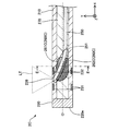
- FIG. 13 is an explanatory diagram illustrating the configuration of the light irradiation device 2F of the seventh embodiment.
- the light irradiation system of the seventh embodiment includes the catheter 1 described in the first embodiment and the light irradiation device 2F shown in FIG.
- the light irradiation device 2F is not provided with the tip 220, is provided with an optical fiber 250F instead of the optical fiber 250, and is provided with a holding member 260F instead of the holding member 260.
- the holding member 260F covers the periphery of the curved portion 251 protruding from the shaft 210. In other words, the holding member 260F covers the entire surface of the curved portion 251 protruding from the shaft 210 in the circumferential direction.
- the holding member 260F has a shape in which the diameter is reduced from the base end side toward the tip end side and the tip end portion is rounded.
- the holding member 260F is provided along the curved portion 251 curved in the + Y axis direction, the reduced diameter shape of the holding member 260 is asymmetric with respect to the axis O in the cross section shown in FIG.
- the maximum outer diameter of the holding member 260F is the same as the outer diameter ⁇ 3 of the shaft 210 (in other words, the outer diameter ⁇ 3 of the light irradiation device 2F).
- the material and refractive index of the holding member 260F are the same as those in the first embodiment.
- the configuration of the light irradiation device 2F can be variously changed, and the curved portion 251 of the optical fiber 250F protrudes from the shaft 210, and further includes a holding member 260F that covers the periphery of the protruding curved portion 251. May be done.
- the shape of the holding member 260F can be arbitrarily changed.
- the holding member 260F may cover at least a part of the curved portion 251 protruding from the shaft 210, not the entire circumferential direction.
- the light irradiation system of the seventh embodiment as described above can also achieve the same effect as that of the first embodiment described above.
- the tip of the optical fiber 250F is formed by projecting a part of the curved portion 251 on the tip end side, that is, the tip of the optical fiber 250F from the tip of the shaft 210 (hollow shaft). It is possible to prevent the light LT emitted from the shaft 210 from being blocked by the shaft 210. Further, since the holding member 260F covers the periphery of the protruding curved portion 251, the periphery of the protruding curved portion 251 can be protected.
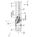
- FIG. 14 is an explanatory diagram illustrating the configuration of the light irradiation device 2G according to the eighth embodiment.
- the light irradiation system of the eighth embodiment includes the catheter 1 described in the first embodiment and the light irradiation device 2G shown in FIG.
- the light irradiation device 2G includes a holding member 260G having a shape different from that of the seventh embodiment in a configuration in which the curved portion 251 of the optical fiber 250F described in the seventh embodiment protrudes from the shaft 210.
- the holding member 260G covers the periphery of the curved portion 251 protruding from the shaft 210 (the entire surface in the circumferential direction).
- the holding member 260G is a substantially cylindrical member having a substantially constant outer diameter, and the outer diameter of the holding member 260G is substantially the same as the outer diameter ⁇ 3 of the shaft 210.
- the holding member 260G is joined to the tip of the shaft 210. Any bonding agent such as an epoxy adhesive can be used for bonding.
- Any bonding agent such as an epoxy adhesive can be used for bonding.
- the configuration of the light irradiation device 2G can be changed in various ways, and the holding member 260G having a shape different from that of the seventh embodiment may be provided.
- the light irradiation system of the eighth embodiment as described above can also achieve the same effect as that of the first and seventh embodiments described above.
- FIG. 15 is an explanatory diagram illustrating the configuration of the light irradiation device 2H of the ninth embodiment.
- the light irradiation system of the ninth embodiment includes the catheter 1 described in the first embodiment and the light irradiation device 2H shown in FIG.
- the light irradiation device 2H includes a holding member 260H having a shape different from that of the seventh embodiment in a configuration in which the curved portion 251 of the optical fiber 250F described in the seventh embodiment protrudes from the shaft 210.
- the holding member 260H includes a tip end side holding member 261H and a proximal end side holding member 262H.
- the tip side holding member 261H is arranged at the tip of the light irradiation device 2H, and covers the periphery of the tip side (the entire surface in the circumferential direction) of the curved portion 251 protruding from the shaft 210.
- the base end side holding member 262H is arranged between the tip end side holding member 261H and the shaft 210, and covers the periphery of the base end side (the entire surface in the circumferential direction) of the curved portion 251 protruding from the shaft 210. ing.
- the tip end side holding member 261H and the proximal end side holding member 262H are both substantially cylindrical members having a substantially constant outer diameter.
- Both the outer diameter of the tip end side holding member 261H and the outer diameter of the proximal end side holding member 262H are substantially the same as the outer diameter ⁇ 3 of the shaft 210.
- the configuration of the light irradiation device 2H can be changed in various ways, and the holding member 260H having a shape different from that of the seventh embodiment may be provided.
- the light irradiation system of the ninth embodiment as described above can also achieve the same effects as those of the first and seventh embodiments described above.
- FIG. 16 is an explanatory diagram illustrating the configuration of the light irradiation device 2I of the tenth embodiment.
- the light irradiation system of the tenth embodiment includes the catheter 1 described in the first embodiment and the light irradiation device 2I shown in FIG.
- the light irradiation device 2I includes a shaft 210I instead of the shaft 210, an optical fiber 250I instead of the optical fiber 250, and a light irradiation unit 239I instead of the light irradiation unit 239.
- the shaft 210I has a hollow substantially cylindrical shape in which both ends of the tip end portion and the base end portion are open. Unlike the shaft 210 of the first embodiment, the shaft 210I is not formed with an opening for exposing the tip of the optical fiber 250I. Further, in the shaft 210I, the portion where the tip of the optical fiber 250I abuts is formed of a light transmissive resin, and is configured to allow the laser beam LT to pass through. Similar to the optical fiber 250 of the first embodiment, the optical fiber 250I has a curved portion 251 formed at the tip of the optical fiber 250I in which the optical fiber 250I is curved in the + Y axis direction.
- the optical fiber 250I is arranged so that its tip (tip surface) is in contact with the inner peripheral surface of the shaft 210I.
- the light LT emitted from the core 250c exposed at the tip of the optical fiber 250I passes through the shaft 210I and is irradiated to the outside. Therefore, in the present embodiment, a part of the shaft 210I functions as the light irradiation unit 239I.
- the configuration of the light irradiation device 2I can be changed in various ways, and the tip of the optical fiber 250I does not have to be exposed on the outer peripheral surface of the shaft 210I.
- the optical LT may be transmitted by making the wall thickness of the portion of the shaft 210I that the tip of the optical fiber 250I abuts is thinner than that of the other portions.
- a resin body or a light reflection mirror for transmitting, refracting, and amplifying the optical LT may be provided on the portion of the shaft 210I where the tip of the optical fiber 250I abuts.
- the entire shaft 210I may be formed of a light-transmitting resin.
- the light irradiation system of the tenth embodiment as described above can also achieve the same effect as that of the first embodiment described above.
- FIG. 17 is an explanatory diagram illustrating the configuration of the light irradiation system of the eleventh embodiment.
- the light irradiation system of the eleventh embodiment includes the catheter 1 described in the first embodiment and the light irradiation device 2J shown in FIG.
- the light irradiation device 2J does not include the shaft 210, the tip tip 220, and the connector 240 described in the first embodiment, and is composed of an optical fiber 250J and a holding member 260J.
- the configuration of the optical fiber 250J is the same as that of the optical fiber 250 described in the first embodiment, and the configuration of the holding member 260J is the same as that of the holding member 260 described in the first embodiment.
- the configuration of the light irradiation device 2J can be changed in various ways, and it is not necessary to include at least a part of the shaft 210, the tip tip 220, and the connector 240.
- the light irradiation system of the eleventh embodiment as described above can also achieve the same effect as that of the first embodiment described above.
- the configuration of the light irradiation device 2J can be simplified, the light irradiation device 2J can be easily manufactured and the manufacturing cost of the light irradiation device 2J can be reduced. ..
- the diameter of the light irradiation device 2J can be reduced, it is possible to deliver the device from the forceps opening of a small-diameter endoscope such as an oral endoscope or a nasal endoscope.
- a reinforcing layer made of a braided body or a coil body may be embedded in the shaft 110 of the catheter 1 and the shaft 210 of the light irradiation device 2.
- the torque transmission property and the shape retention property of the catheter 1 and the light irradiation device 2 can be improved.
- the outer surface of the catheter 1 and the outer surface of the light irradiation device 2 may be coated with a hydrophilic or hydrophobic resin. In this way, the slipperiness of the catheter 1 in the living lumen can be improved. In addition, the slipperiness of the light irradiation device 2 in the lumen 110L of the catheter 1 can be improved.
- an antithrombotic material such as heparin may be coated on the outer surface of the catheter 1 or the outer surface of the light irradiation device 2. In this way, it is possible to suppress a decrease in laser output due to thrombus adhesion to the inner and outer surfaces of the catheter 1 and the outer surface of the light irradiation device 2 due to irradiation with emitted light (laser light) LT.
- the catheter 1 may be provided with an expansion portion that can be expanded in the radial direction (YZ direction).
- the expansion portion for example, a balloon made of a flexible thin film or a mesh body having a mesh of strands can be used.
- the extension portion may be provided on at least one of the tip end side of the light transmitting portion 139 and the proximal end side of the light transmitting portion 139 in the shaft 110. In this way, the catheter 1 can be fixed in the living lumen by expanding the dilated portion after positioning the catheter 1 in the living lumen. Further, if a balloon is used as the expansion portion, the blood flow at the light irradiation site can be blocked, so that the blockage of light due to the blood flow can be suppressed.
- the catheter 1 may be configured as a multi-lumen catheter having a plurality of lumens different from the lumen 110L.
- the light irradiation device 2 may be configured as a multi-lumen catheter having a separate lumen different from the lumen 210 L through which the first optical fiber 250 is inserted.
- the shaft 210 may be made of a hollow, substantially cylindrical member, and the tip tip 220 may be provided with a through hole extending along the axis O direction.
- the inner surface of the tip tip 120 of the catheter 1 and the outer surface of the tip tip 220 of the light irradiation device 2 may be formed of a magnetic material so as to attract each other.
- the light irradiation device 2 can be inserted into the catheter 1 and the state in which the tip tip 220 is pressed against the tip tip 120 can be easily maintained.
- the tip 120 of the tip of the catheter 1 may be omitted, and a configuration in which the tip of the shaft 110 is open may be adopted.
- the curved portion 251 for crossing the tip of the optical fiber 250 in the long axis direction of the light irradiation device 2 is not limited to the shape shown in the figure, and any shape can be adopted.
- the optical fiber 250 may have a separate curved portion different from the curved portion 251 for crossing the tip of the optical fiber 250 in the long axis direction of the light irradiation device 2.
- This curved portion may be provided, for example, on the proximal end side of the curved portion 251.
- the shape of the curved portion can be arbitrarily determined, and can be, for example, a spiral shape along the inner peripheral surface of the shaft 210, a wavy shape, or a bellows shape.
- the range of the outer holding member in the long axis direction (axis O direction) can be arbitrarily determined.
- the outer holding member arranged adjacent to the outer peripheral side of the curved portion 251 may be provided up to the tip of the shaft 210 (the boundary surface between the shaft 210 and the tip tip 220).
- the light irradiation device 2 does not include an inner holding member arranged adjacent to the inner peripheral side of the curved portion 251 but includes only an outer holding member arranged adjacent to the outer peripheral side of the curved portion 251. You may be.
- the outer holding member arranged adjacent to the outer peripheral side of the curved portion 251 the first outer holding member arranged on the tip side and the second outer holding member arranged on the proximal end side.
- An outer holding member may be provided.
- the outer holding member arranged adjacent to the outer peripheral side of the curved portion 251 may include three or more outer holding members.
- the configurations of the light transmitting unit 139 and the light irradiating unit 239, 239I can be changed in various ways.
- the light transmitting portion 139 and the first marker portions 131 and 132 may be integrally formed by forming the light transmitting portion 139 with a material having radiation opacity.
- the tip portion (light irradiation portion 239) of the clad 250cl with a material having radiation opacity are integrally formed. May be good.
- the light transmitting portion 139 may be formed by thinning a part of the shaft 110.
- at least one of the light transmitting portions 139 may be formed as a notch (through hole communicating inside and outside the shaft) formed in the shaft 110.
- the light transmitting portion 139 can be easily formed.
- the range of the axis O direction (X axis direction) and the range of the circumferential direction (YZ axis direction) in which the light transmitting portion 139 is provided can be arbitrarily changed.
- the light transmitting portion 139 may be provided in a wide range in the axis O direction.
- the catheter 1 may further be provided with a separate marker portion arranged at an arbitrary position, such as the distal end side of the light transmitting portion 139 or the proximal end side of the light transmitting portion 139.
- the light irradiation device 2 may further include a separate marker unit arranged at an arbitrary position such as the tip end side of the light irradiation unit 239 or the base end side of the light irradiation unit 239.
- the shape of the marker portion of the catheter 1 and the light irradiation device 2 can be arbitrarily determined, and may be a shape extending in the entire or a part of the circumferential direction (YZ direction) or a shape extending in the axis O direction (X-axis direction). , It may be a shape that surrounds the circumference of the shaft.
- the tip 120 of the catheter 1 and the tip 220 of the light irradiation device 2 may be configured as a marker portion.
- Inner holding member 261D First inner holding member 261H ... Tip side holding member 262,262C, 262D ... Outer holding member 262H ... Base end side holding member 263D ... Second inner Holding member 270 ... Resin member
Abstract
L'invention concerne un dispositif électroluminescent ayant une forme allongée, qui est une fibre optique qui émet de la lumière à partir de sa pointe, le dispositif électroluminescent comprenant : une fibre optique qui a une section incurvée et dans laquelle la pointe fait face à une direction croisant la direction longitudinale de la fibre optique en raison de la section incurvée ; et un élément de support transmettant la lumière qui maintient la forme de la section incurvée de la fibre optique. La fibre optique a un coeur, ou possède un noyau et une pluralité de couches de recouvrement, et l'indice de réfraction de l'élément de maintien est inférieur à l'indice de réfraction d'un élément qui constitue la surface extérieure de la fibre optique.
Priority Applications (3)
| Application Number | Priority Date | Filing Date | Title |
|---|---|---|---|
| EP20876373.0A EP4046586A4 (fr) | 2019-10-17 | 2020-08-17 | Dispositif électroluminescent et système électroluminescent |
| CN202080070103.9A CN114514051A (zh) | 2019-10-17 | 2020-08-17 | 光照射设备以及光照射系统 |
| US17/714,637 US11874455B2 (en) | 2019-10-17 | 2022-04-06 | Light irradiation device and light irradiation system |
Applications Claiming Priority (2)
| Application Number | Priority Date | Filing Date | Title |
|---|---|---|---|
| JP2019190447A JP7308123B2 (ja) | 2019-10-17 | 2019-10-17 | 光照射デバイス、及び、光照射システム |
| JP2019-190447 | 2019-10-17 |
Related Child Applications (1)
| Application Number | Title | Priority Date | Filing Date |
|---|---|---|---|
| US17/714,637 Continuation US11874455B2 (en) | 2019-10-17 | 2022-04-06 | Light irradiation device and light irradiation system |
Publications (1)
| Publication Number | Publication Date |
|---|---|
| WO2021075140A1 true WO2021075140A1 (fr) | 2021-04-22 |
Family
ID=75537798
Family Applications (1)
| Application Number | Title | Priority Date | Filing Date |
|---|---|---|---|
| PCT/JP2020/030964 WO2021075140A1 (fr) | 2019-10-17 | 2020-08-17 | Dispositif électroluminescent et système électroluminescent |
Country Status (5)
| Country | Link |
|---|---|
| US (1) | US11874455B2 (fr) |
| EP (1) | EP4046586A4 (fr) |
| JP (1) | JP7308123B2 (fr) |
| CN (1) | CN114514051A (fr) |
| WO (1) | WO2021075140A1 (fr) |
Families Citing this family (1)
| Publication number | Priority date | Publication date | Assignee | Title |
|---|---|---|---|---|
| WO2024062901A1 (fr) * | 2022-09-21 | 2024-03-28 | 古河電気工業株式会社 | Sonde à fibre optique |
Citations (6)
| Publication number | Priority date | Publication date | Assignee | Title |
|---|---|---|---|---|
| US4747661A (en) * | 1986-05-15 | 1988-05-31 | Olympus Optical Co., Ltd. | Endoscope tip adaptor |
| JP2001037892A (ja) | 1999-07-30 | 2001-02-13 | Terumo Corp | レーザ照射装置 |
| JP2005237827A (ja) * | 2004-02-27 | 2005-09-08 | Terumo Corp | 治療用カテーテルおよび治療装置 |
| US20090287197A1 (en) * | 2008-05-19 | 2009-11-19 | Hanley Brian M | Side-firing laser fiber with internal bent fiber and related methods |
| KR20160029270A (ko) * | 2014-09-05 | 2016-03-15 | 민규석 | 광섬유 어셈블리 |
| JP2018000867A (ja) | 2016-07-08 | 2018-01-11 | 株式会社アライ・メッドフォトン研究所 | カテーテルチューブ |
Family Cites Families (12)
| Publication number | Priority date | Publication date | Assignee | Title |
|---|---|---|---|---|
| US3123066A (en) * | 1964-03-03 | brumley | ||
| US4747405A (en) * | 1984-03-01 | 1988-05-31 | Vaser, Inc. | Angioplasty catheter |
| US4669467A (en) * | 1985-03-22 | 1987-06-02 | Massachusetts Institute Of Technology | Mode mixer for a laser catheter |
| US4852567A (en) * | 1988-01-21 | 1989-08-01 | C. R. Bard, Inc. | Laser tipped catheter |
| JP2779825B2 (ja) * | 1989-02-15 | 1998-07-23 | 則雄 大工園 | レーザ光出射装置 |
| JP3467268B2 (ja) * | 1990-08-06 | 2003-11-17 | アキュレイズ,インコーポレイテッド | ファイバー光学によるレーザーカテーテル |
| US5495541A (en) * | 1994-04-19 | 1996-02-27 | Murray; Steven C. | Optical delivery device with high numerical aperture curved waveguide |
| ATE314016T1 (de) | 1999-07-30 | 2006-01-15 | Terumo Corp | Laserbestrahlungsgerät |
| JP4388647B2 (ja) * | 1999-10-27 | 2009-12-24 | テルモ株式会社 | レーザ照射装置 |
| ATE548079T1 (de) | 2003-07-09 | 2012-03-15 | Light Sciences Oncology Inc | Vorrichtung zum distalen schutz und behandlung von blutgefässen |
| US20070073277A1 (en) | 2005-09-16 | 2007-03-29 | Medicalcv, Inc. | Controlled guided ablation treatment |
| CN103781495A (zh) | 2011-07-11 | 2014-05-07 | 美国政府(由卫生和人类服务部的部长所代表) | 光敏抗体-荧光团缀合物 |
-
2019
- 2019-10-17 JP JP2019190447A patent/JP7308123B2/ja active Active
-
2020
- 2020-08-17 CN CN202080070103.9A patent/CN114514051A/zh not_active Withdrawn
- 2020-08-17 WO PCT/JP2020/030964 patent/WO2021075140A1/fr unknown
- 2020-08-17 EP EP20876373.0A patent/EP4046586A4/fr active Pending
-
2022
- 2022-04-06 US US17/714,637 patent/US11874455B2/en active Active
Patent Citations (6)
| Publication number | Priority date | Publication date | Assignee | Title |
|---|---|---|---|---|
| US4747661A (en) * | 1986-05-15 | 1988-05-31 | Olympus Optical Co., Ltd. | Endoscope tip adaptor |
| JP2001037892A (ja) | 1999-07-30 | 2001-02-13 | Terumo Corp | レーザ照射装置 |
| JP2005237827A (ja) * | 2004-02-27 | 2005-09-08 | Terumo Corp | 治療用カテーテルおよび治療装置 |
| US20090287197A1 (en) * | 2008-05-19 | 2009-11-19 | Hanley Brian M | Side-firing laser fiber with internal bent fiber and related methods |
| KR20160029270A (ko) * | 2014-09-05 | 2016-03-15 | 민규석 | 광섬유 어셈블리 |
| JP2018000867A (ja) | 2016-07-08 | 2018-01-11 | 株式会社アライ・メッドフォトン研究所 | カテーテルチューブ |
Non-Patent Citations (4)
| Title |
|---|
| KAZUHIDE SATONORIKO SATOBIYING XUYUKO NAKAMURATADANOBU NAGAYAPETER L. CHOYKEYOSHINORI HASEGAWAHISATAKA KOBAYASHI: "Spatially selective depletion of tumor-associated regulatory T cells with near-infrared photoimmunotherapy", SCIENCE TRANSLATIONAL MEDICINE, vol. 8, 2016, pages ra110 |
| MAKOTO MITSUNAGAMIKAKO OGAWANOBUYUKI KOSAKA LAUREN T. ROSENBLUMPETER L. CHOYKEHISATAKA KOBAYASHI: "Cancer Cell-Selective In Vivo Near Infrared Photoimmunotherapy Targeting Specific Membrane Molecules", NATURE MEDICINE, vol. 17, no. 12, 2012, pages 1685 - 1691, XP002683826, DOI: 10.1038/NM.2554 |
| See also references of EP4046586A4 |
| SHUHEI OKUYAMATADANOBU NAGAYAKAZUHIDE SATOFUSA OGATAYASUHIRO MARUOKAPETER L. CHOYKEHISATAKA KOBAYASHI: "Interstitial near-infrared photoimmunotherapy: effective treatment areas and light doses needed for use with fiber optic diffusers", ONCOTARGET, vol. 9, no. 13, 16 February 2018 (2018-02-16), pages 11159 - 11169 |
Also Published As
| Publication number | Publication date |
|---|---|
| US20220229282A1 (en) | 2022-07-21 |
| JP2021065256A (ja) | 2021-04-30 |
| JP7308123B2 (ja) | 2023-07-13 |
| EP4046586A4 (fr) | 2023-11-15 |
| EP4046586A1 (fr) | 2022-08-24 |
| CN114514051A (zh) | 2022-05-17 |
| US11874455B2 (en) | 2024-01-16 |
Similar Documents
| Publication | Publication Date | Title |
|---|---|---|
| US20220047884A1 (en) | Light irradiation device and light irradiation system | |
| JP2021090503A (ja) | 光照射デバイス | |
| WO2021075140A1 (fr) | Dispositif électroluminescent et système électroluminescent | |
| WO2021075141A1 (fr) | Dispositif et système d'irradiation de lumière | |
| US20220161046A1 (en) | Catheter and light irradiation system | |
| WO2021059797A1 (fr) | Dispositif d'irradiation de lumière et système d'irradiation de lumière | |
| WO2020230516A1 (fr) | Systeme de rayonnement lumineux, catheter et dispositif de rayonnement lumineux | |
| WO2021059798A1 (fr) | Dispositif d'irradiation de lumière et système d'irradiation de lumière | |
| WO2022029920A1 (fr) | Dispositif et système d'irradiation de lumière | |
| WO2021019981A1 (fr) | Cathéter et système d'irradiation de lumière | |
| WO2020230518A1 (fr) | Systeme de rayonnement lumineux, catheter et dispositif de rayonnement lumineux | |
| JP2023048292A (ja) | 光照射システム | |
| JP2021090504A (ja) | 光照射デバイス | |
| JP7340174B2 (ja) | 光照射システム | |
| JP2021083661A (ja) | 光照射デバイス | |
| WO2021070476A1 (fr) | Cathéter et dispositif d'irradiation de lumière | |
| JP2022075134A (ja) | 光照射デバイス、及び、光照射システム |
Legal Events
| Date | Code | Title | Description |
|---|---|---|---|
| 121 | Ep: the epo has been informed by wipo that ep was designated in this application |
Ref document number: 20876373 Country of ref document: EP Kind code of ref document: A1 |
|
| NENP | Non-entry into the national phase |
Ref country code: DE |
|
| ENP | Entry into the national phase |
Ref document number: 2020876373 Country of ref document: EP Effective date: 20220517 |