WO2021075140A1 - Light emitting device and light emitting system - Google Patents
Light emitting device and light emitting system Download PDFInfo
- Publication number
- WO2021075140A1 WO2021075140A1 PCT/JP2020/030964 JP2020030964W WO2021075140A1 WO 2021075140 A1 WO2021075140 A1 WO 2021075140A1 JP 2020030964 W JP2020030964 W JP 2020030964W WO 2021075140 A1 WO2021075140 A1 WO 2021075140A1
- Authority
- WO
- WIPO (PCT)
- Prior art keywords
- holding member
- light irradiation
- irradiation device
- optical fiber
- tip
- Prior art date
Links
- 239000013307 optical fiber Substances 0.000 claims abstract description 154
- 229920005989 resin Polymers 0.000 claims description 61
- 239000011347 resin Substances 0.000 claims description 61
- 230000002093 peripheral effect Effects 0.000 claims description 55
- 239000011247 coating layer Substances 0.000 claims description 5
- 239000003550 marker Substances 0.000 description 31
- 239000000463 material Substances 0.000 description 15
- 230000000694 effects Effects 0.000 description 14
- 206010028980 Neoplasm Diseases 0.000 description 12
- 238000010586 diagram Methods 0.000 description 12
- 238000000034 method Methods 0.000 description 12
- 238000002428 photodynamic therapy Methods 0.000 description 11
- 201000011510 cancer Diseases 0.000 description 10
- 239000000126 substance Substances 0.000 description 9
- 210000004027 cell Anatomy 0.000 description 8
- 238000012986 modification Methods 0.000 description 7
- 230000004048 modification Effects 0.000 description 7
- 238000011282 treatment Methods 0.000 description 7
- 230000001678 irradiating effect Effects 0.000 description 6
- 229920000642 polymer Polymers 0.000 description 5
- 230000005540 biological transmission Effects 0.000 description 4
- 210000004907 gland Anatomy 0.000 description 4
- 239000007769 metal material Substances 0.000 description 4
- 230000003014 reinforcing effect Effects 0.000 description 4
- 210000001519 tissue Anatomy 0.000 description 4
- XUIMIQQOPSSXEZ-UHFFFAOYSA-N Silicon Chemical compound [Si] XUIMIQQOPSSXEZ-UHFFFAOYSA-N 0.000 description 3
- 230000003287 optical effect Effects 0.000 description 3
- -1 polyethylene terephthalate Polymers 0.000 description 3
- 238000012545 processing Methods 0.000 description 3
- 230000005855 radiation Effects 0.000 description 3
- 239000010703 silicon Substances 0.000 description 3
- 229910052710 silicon Inorganic materials 0.000 description 3
- WFKWXMTUELFFGS-UHFFFAOYSA-N tungsten Chemical compound [W] WFKWXMTUELFFGS-UHFFFAOYSA-N 0.000 description 3
- 229910052721 tungsten Inorganic materials 0.000 description 3
- 239000010937 tungsten Substances 0.000 description 3
- YCKRFDGAMUMZLT-UHFFFAOYSA-N Fluorine atom Chemical compound [F] YCKRFDGAMUMZLT-UHFFFAOYSA-N 0.000 description 2
- VYPSYNLAJGMNEJ-UHFFFAOYSA-N Silicium dioxide Chemical compound O=[Si]=O VYPSYNLAJGMNEJ-UHFFFAOYSA-N 0.000 description 2
- 238000009825 accumulation Methods 0.000 description 2
- 230000002785 anti-thrombosis Effects 0.000 description 2
- TZCXTZWJZNENPQ-UHFFFAOYSA-L barium sulfate Chemical compound [Ba+2].[O-]S([O-])(=O)=O TZCXTZWJZNENPQ-UHFFFAOYSA-L 0.000 description 2
- 210000003445 biliary tract Anatomy 0.000 description 2
- 230000017531 blood circulation Effects 0.000 description 2
- 210000004204 blood vessel Anatomy 0.000 description 2
- 210000002249 digestive system Anatomy 0.000 description 2
- 239000011737 fluorine Substances 0.000 description 2
- 229910052731 fluorine Inorganic materials 0.000 description 2
- 239000010410 layer Substances 0.000 description 2
- 210000002751 lymph Anatomy 0.000 description 2
- 238000004519 manufacturing process Methods 0.000 description 2
- 210000000056 organ Anatomy 0.000 description 2
- 239000013308 plastic optical fiber Substances 0.000 description 2
- BASFCYQUMIYNBI-UHFFFAOYSA-N platinum Chemical compound [Pt] BASFCYQUMIYNBI-UHFFFAOYSA-N 0.000 description 2
- 229920003229 poly(methyl methacrylate) Polymers 0.000 description 2
- 229920006122 polyamide resin Polymers 0.000 description 2
- 239000004417 polycarbonate Substances 0.000 description 2
- 229920000515 polycarbonate Polymers 0.000 description 2
- 229920001225 polyester resin Polymers 0.000 description 2
- 239000004645 polyester resin Substances 0.000 description 2
- 239000004926 polymethyl methacrylate Substances 0.000 description 2
- 229920005672 polyolefin resin Polymers 0.000 description 2
- 229920005749 polyurethane resin Polymers 0.000 description 2
- 239000000843 powder Substances 0.000 description 2
- 230000001850 reproductive effect Effects 0.000 description 2
- 230000003248 secreting effect Effects 0.000 description 2
- 210000001635 urinary tract Anatomy 0.000 description 2
- 230000002792 vascular Effects 0.000 description 2
- 229920000178 Acrylic resin Polymers 0.000 description 1
- 239000004925 Acrylic resin Substances 0.000 description 1
- HTTJABKRGRZYRN-UHFFFAOYSA-N Heparin Chemical compound OC1C(NC(=O)C)C(O)OC(COS(O)(=O)=O)C1OC1C(OS(O)(=O)=O)C(O)C(OC2C(C(OS(O)(=O)=O)C(OC3C(C(O)C(O)C(O3)C(O)=O)OS(O)(=O)=O)C(CO)O2)NS(O)(=O)=O)C(C(O)=O)O1 HTTJABKRGRZYRN-UHFFFAOYSA-N 0.000 description 1
- 229910000990 Ni alloy Inorganic materials 0.000 description 1
- 229920001609 Poly(3,4-ethylenedioxythiophene) Polymers 0.000 description 1
- 229930182556 Polyacetal Natural products 0.000 description 1
- 239000004952 Polyamide Substances 0.000 description 1
- 239000004695 Polyether sulfone Substances 0.000 description 1
- 239000004743 Polypropylene Substances 0.000 description 1
- 239000004793 Polystyrene Substances 0.000 description 1
- 229910000831 Steel Inorganic materials 0.000 description 1
- 208000007536 Thrombosis Diseases 0.000 description 1
- WAIPAZQMEIHHTJ-UHFFFAOYSA-N [Cr].[Co] Chemical class [Cr].[Co] WAIPAZQMEIHHTJ-UHFFFAOYSA-N 0.000 description 1
- NIXOWILDQLNWCW-UHFFFAOYSA-N acrylic acid group Chemical group C(C=C)(=O)O NIXOWILDQLNWCW-UHFFFAOYSA-N 0.000 description 1
- 229910045601 alloy Inorganic materials 0.000 description 1
- 239000000956 alloy Substances 0.000 description 1
- 230000001093 anti-cancer Effects 0.000 description 1
- 239000003146 anticoagulant agent Substances 0.000 description 1
- 239000000427 antigen Substances 0.000 description 1
- 102000036639 antigens Human genes 0.000 description 1
- 108091007433 antigens Proteins 0.000 description 1
- QVGXLLKOCUKJST-UHFFFAOYSA-N atomic oxygen Chemical compound [O] QVGXLLKOCUKJST-UHFFFAOYSA-N 0.000 description 1
- WMWLMWRWZQELOS-UHFFFAOYSA-N bismuth(III) oxide Inorganic materials O=[Bi]O[Bi]=O WMWLMWRWZQELOS-UHFFFAOYSA-N 0.000 description 1
- 239000007767 bonding agent Substances 0.000 description 1
- 150000001875 compounds Chemical class 0.000 description 1
- 238000005520 cutting process Methods 0.000 description 1
- 238000013461 design Methods 0.000 description 1
- 238000011161 development Methods 0.000 description 1
- 238000009826 distribution Methods 0.000 description 1
- 239000003814 drug Substances 0.000 description 1
- 229940079593 drug Drugs 0.000 description 1
- 229920006332 epoxy adhesive Polymers 0.000 description 1
- 239000003822 epoxy resin Substances 0.000 description 1
- 230000005284 excitation Effects 0.000 description 1
- 239000011521 glass Substances 0.000 description 1
- PCHJSUWPFVWCPO-UHFFFAOYSA-N gold Chemical compound [Au] PCHJSUWPFVWCPO-UHFFFAOYSA-N 0.000 description 1
- 239000010931 gold Substances 0.000 description 1
- 229910052737 gold Inorganic materials 0.000 description 1
- 229960002897 heparin Drugs 0.000 description 1
- 229920000669 heparin Polymers 0.000 description 1
- 230000002209 hydrophobic effect Effects 0.000 description 1
- 210000000987 immune system Anatomy 0.000 description 1
- 239000000696 magnetic material Substances 0.000 description 1
- 230000014759 maintenance of location Effects 0.000 description 1
- PCLURTMBFDTLSK-UHFFFAOYSA-N nickel platinum Chemical compound [Ni].[Pt] PCLURTMBFDTLSK-UHFFFAOYSA-N 0.000 description 1
- 229910001000 nickel titanium Inorganic materials 0.000 description 1
- JFNLZVQOOSMTJK-KNVOCYPGSA-N norbornene Chemical compound C1[C@@H]2CC[C@H]1C=C2 JFNLZVQOOSMTJK-KNVOCYPGSA-N 0.000 description 1
- 229910052760 oxygen Inorganic materials 0.000 description 1
- 239000001301 oxygen Substances 0.000 description 1
- 230000035699 permeability Effects 0.000 description 1
- 229910052697 platinum Inorganic materials 0.000 description 1
- 229920002647 polyamide Polymers 0.000 description 1
- 229920000647 polyepoxide Polymers 0.000 description 1
- 229920006393 polyether sulfone Polymers 0.000 description 1
- 229920000139 polyethylene terephthalate Polymers 0.000 description 1
- 239000005020 polyethylene terephthalate Substances 0.000 description 1
- 229920006324 polyoxymethylene Polymers 0.000 description 1
- 229920001155 polypropylene Polymers 0.000 description 1
- 229920002223 polystyrene Polymers 0.000 description 1
- 229920002635 polyurethane Polymers 0.000 description 1
- 239000004814 polyurethane Substances 0.000 description 1
- 229920003225 polyurethane elastomer Polymers 0.000 description 1
- 229920000915 polyvinyl chloride Polymers 0.000 description 1
- 239000004800 polyvinyl chloride Substances 0.000 description 1
- 239000010453 quartz Substances 0.000 description 1
- 238000011160 research Methods 0.000 description 1
- 230000000717 retained effect Effects 0.000 description 1
- 238000005488 sandblasting Methods 0.000 description 1
- 239000010935 stainless steel Substances 0.000 description 1
- 229910001220 stainless steel Inorganic materials 0.000 description 1
- 239000010959 steel Substances 0.000 description 1
- 230000001225 therapeutic effect Effects 0.000 description 1
- 239000010409 thin film Substances 0.000 description 1
- 239000011800 void material Substances 0.000 description 1
Images


Classifications
-
- G—PHYSICS
- G02—OPTICS
- G02B—OPTICAL ELEMENTS, SYSTEMS OR APPARATUS
- G02B6/00—Light guides; Structural details of arrangements comprising light guides and other optical elements, e.g. couplings
- G02B6/24—Coupling light guides
- G02B6/36—Mechanical coupling means
- G02B6/3616—Holders, macro size fixtures for mechanically holding or positioning fibres, e.g. on an optical bench
- G02B6/3624—Fibre head, e.g. fibre probe termination
-
- A—HUMAN NECESSITIES
- A61—MEDICAL OR VETERINARY SCIENCE; HYGIENE
- A61N—ELECTROTHERAPY; MAGNETOTHERAPY; RADIATION THERAPY; ULTRASOUND THERAPY
- A61N5/00—Radiation therapy
- A61N5/06—Radiation therapy using light
- A61N5/0613—Apparatus adapted for a specific treatment
- A61N5/062—Photodynamic therapy, i.e. excitation of an agent
-
- A—HUMAN NECESSITIES
- A61—MEDICAL OR VETERINARY SCIENCE; HYGIENE
- A61B—DIAGNOSIS; SURGERY; IDENTIFICATION
- A61B18/00—Surgical instruments, devices or methods for transferring non-mechanical forms of energy to or from the body
- A61B18/18—Surgical instruments, devices or methods for transferring non-mechanical forms of energy to or from the body by applying electromagnetic radiation, e.g. microwaves
- A61B18/20—Surgical instruments, devices or methods for transferring non-mechanical forms of energy to or from the body by applying electromagnetic radiation, e.g. microwaves using laser
- A61B18/22—Surgical instruments, devices or methods for transferring non-mechanical forms of energy to or from the body by applying electromagnetic radiation, e.g. microwaves using laser the beam being directed along or through a flexible conduit, e.g. an optical fibre; Couplings or hand-pieces therefor
- A61B18/24—Surgical instruments, devices or methods for transferring non-mechanical forms of energy to or from the body by applying electromagnetic radiation, e.g. microwaves using laser the beam being directed along or through a flexible conduit, e.g. an optical fibre; Couplings or hand-pieces therefor with a catheter
-
- A—HUMAN NECESSITIES
- A61—MEDICAL OR VETERINARY SCIENCE; HYGIENE
- A61N—ELECTROTHERAPY; MAGNETOTHERAPY; RADIATION THERAPY; ULTRASOUND THERAPY
- A61N5/00—Radiation therapy
- A61N5/06—Radiation therapy using light
- A61N5/0601—Apparatus for use inside the body
-
- G—PHYSICS
- G02—OPTICS
- G02B—OPTICAL ELEMENTS, SYSTEMS OR APPARATUS
- G02B23/00—Telescopes, e.g. binoculars; Periscopes; Instruments for viewing the inside of hollow bodies; Viewfinders; Optical aiming or sighting devices
- G02B23/24—Instruments or systems for viewing the inside of hollow bodies, e.g. fibrescopes
- G02B23/2407—Optical details
- G02B23/2461—Illumination
- G02B23/2469—Illumination using optical fibres
-
- A—HUMAN NECESSITIES
- A61—MEDICAL OR VETERINARY SCIENCE; HYGIENE
- A61N—ELECTROTHERAPY; MAGNETOTHERAPY; RADIATION THERAPY; ULTRASOUND THERAPY
- A61N5/00—Radiation therapy
- A61N5/06—Radiation therapy using light
- A61N5/0601—Apparatus for use inside the body
- A61N2005/0602—Apparatus for use inside the body for treatment of blood vessels
-
- A—HUMAN NECESSITIES
- A61—MEDICAL OR VETERINARY SCIENCE; HYGIENE
- A61N—ELECTROTHERAPY; MAGNETOTHERAPY; RADIATION THERAPY; ULTRASOUND THERAPY
- A61N5/00—Radiation therapy
- A61N5/06—Radiation therapy using light
- A61N2005/063—Radiation therapy using light comprising light transmitting means, e.g. optical fibres
-
- A—HUMAN NECESSITIES
- A61—MEDICAL OR VETERINARY SCIENCE; HYGIENE
- A61N—ELECTROTHERAPY; MAGNETOTHERAPY; RADIATION THERAPY; ULTRASOUND THERAPY
- A61N5/00—Radiation therapy
- A61N5/06—Radiation therapy using light
- A61N2005/0632—Constructional aspects of the apparatus
-
- A—HUMAN NECESSITIES
- A61—MEDICAL OR VETERINARY SCIENCE; HYGIENE
- A61N—ELECTROTHERAPY; MAGNETOTHERAPY; RADIATION THERAPY; ULTRASOUND THERAPY
- A61N5/00—Radiation therapy
- A61N5/06—Radiation therapy using light
- A61N2005/0658—Radiation therapy using light characterised by the wavelength of light used
- A61N2005/0659—Radiation therapy using light characterised by the wavelength of light used infrared
-
- A—HUMAN NECESSITIES
- A61—MEDICAL OR VETERINARY SCIENCE; HYGIENE
- A61N—ELECTROTHERAPY; MAGNETOTHERAPY; RADIATION THERAPY; ULTRASOUND THERAPY
- A61N5/00—Radiation therapy
- A61N5/06—Radiation therapy using light
- A61N5/067—Radiation therapy using light using laser light
-
- G—PHYSICS
- G02—OPTICS
- G02B—OPTICAL ELEMENTS, SYSTEMS OR APPARATUS
- G02B6/00—Light guides; Structural details of arrangements comprising light guides and other optical elements, e.g. couplings
- G02B6/0001—Light guides; Structural details of arrangements comprising light guides and other optical elements, e.g. couplings specially adapted for lighting devices or systems
- G02B6/0005—Light guides; Structural details of arrangements comprising light guides and other optical elements, e.g. couplings specially adapted for lighting devices or systems the light guides being of the fibre type
- G02B6/0008—Light guides; Structural details of arrangements comprising light guides and other optical elements, e.g. couplings specially adapted for lighting devices or systems the light guides being of the fibre type the light being emitted at the end of the fibre
Definitions
- the present invention relates to a light irradiation device and a light irradiation system.
- PDT Photodynamic Therapy
- a light-sensitive substance is intravenously administered and then irradiated with light to generate active oxygen in cancer cells and kill the cancer cells (see, for example, Non-Patent Document 1).
- PDT has low selectivity for accumulation of light-sensitive substances in cancer cells, and the magnitude of side effects due to its uptake into normal cells becomes an issue, and PDT is not widely used as a therapeutic technique.
- NIR-PIT Near-infrared photoimmunotherapy
- a complex in which two compounds of an antibody against a specific antigen of cancer cells and a photosensitive substance (for example, IRDye700DX) are bound is used.
- this complex selectively accumulates in cancer cells in the body.
- an excitation wavelength for example, 690 nm
- the complex is activated and exhibits an anticancer effect (see, for example, Patent Document 1).
- NIR-PIT performs light irradiation (NIR irradiation) in a near-infrared region of, for example, 690 nm, the effect of NIR irradiation on the immune system can be expected (see, for example, Non-Patent Document 2).
- the predetermined wavelength region including 690 nm exemplified above is also called a spectroscopic window of a living body, and although it is a wavelength region in which light is absorbed less by biological components than other wavelength regions, light irradiation from the body surface is performed.
- a spectroscopic window of a living body although it is a wavelength region in which light is absorbed less by biological components than other wavelength regions, light irradiation from the body surface is performed.
- NIR-PIT in which light irradiation is performed at a position closer to cancer cells instead of light irradiation from the body surface (see, for example, Non-Patent Document 3).
- Patent Documents 2 to 4 disclose devices that can be used in such PDTs and NIR-PITs.
- Patent Documents 2 to 4 All of the devices described in Patent Documents 2 to 4 are used by being inserted into a living lumen such as a blood vessel, and can irradiate a deep part of the body with light transmitted by an optical fiber.
- the device described in Patent Document 5 uses laser light to form a wound in a body tissue.
- the optical fiber generally transmits light by total reflection of light utilizing the difference in refractive index between the core and the clad that covers the outer peripheral surface of the core, and emits light from the core exposed at the tip.
- the light irradiation direction is the direction of the tissue surrounding the living lumen, that is, the direction intersecting the long axis direction of the device. Is preferable.
- the devices described in Patent Documents 4 and 5 are provided with a guide means (guide member), and by moving the optical fiber using the guide means, the tip of the optical fiber is moved in the long axis direction of the device. Can be turned in the direction of intersection with.
- Patent Documents 4 and 5 have a problem that the structure of the device becomes complicated and the diameter of the device becomes large. Further, in the devices described in Patent Documents 2 and 3, no consideration is given to irradiating light in a direction intersecting the long axis direction of the device.
- such a problem is not limited to PDT and NIR-PIT, but is common to all devices used in examinations or treatments including the process of irradiating light in the body. Moreover, such a problem is not limited to the device inserted into the blood vessel, but also in the biological lumen such as the vascular system, the lymph gland system, the biliary system, the urinary tract system, the airway system, the digestive system, the secretory gland and the reproductive organ. Common to all devices inserted in.
- the present invention has been made to solve at least a part of the above-mentioned problems, and in a device capable of irradiating light from an optical fiber in a direction intersecting the long axis direction of the device, the diameter of the device is reduced.
- the purpose is.
- the present invention has been made to solve at least a part of the above-mentioned problems, and can be realized as the following forms.
- a light irradiation device having a long outer shape is provided.
- This light irradiation device is an optical fiber that irradiates light from the tip, and has a curved portion, and the curved portion is directed to a direction in which the tip intersects the long axis direction of the light irradiation device.
- a light-transmitting holding member that holds the shape of the curved portion of the optical fiber, and the optical fiber has a core or a core and one or more coating layers, and the holding member
- the refractive index of is smaller than the refractive index of the members constituting the outer surface of the optical fiber.
- the shape of the curved portion is held by the holding member in a state where the tip of the optical fiber is directed by the curved portion in the direction intersecting the long axis direction of the light irradiation device. Therefore, by moving the optical fiber using the guide means, the configuration of the light irradiation device can be simplified as compared with the configuration in which the tip of the optical fiber is directed in the direction intersecting the long axis direction of the light irradiation device. Therefore, the diameter of the light irradiation device can be reduced. Further, the refractive index of the holding member is smaller than the refractive index of the members constituting the outer surface of the optical fiber.
- a holding member having a refractive index equal to that of the member constituting the outer surface of the optical fiber or a refractive index higher than the refractive index of the member constituting the outer surface of the optical fiber is used to form the curved portion.
- the light inside the optical fiber can be reflected at the boundary between the member constituting the outer surface of the optical fiber and the holding member, as compared with the case where the shape of the optical fiber is maintained.
- the light irradiation device of this configuration the light leaking from the inside of the optical fiber can be reduced.
- the holding member may be arranged at least adjacent to the inner peripheral side of the curved portion.
- the shape of the curved portion of the optical fiber can be maintained at least from the inner peripheral side of the curved portion.
- the inner peripheral side of the curved portion is the direction in which the tip of the optical fiber is facing, that is, the direction in which light is emitted from the optical fiber.
- the substance forming the holding member has a higher refractive index than air.
- the holding member on the outer peripheral side of the curved portion (the direction in which the light is not irradiated from the optical fiber) and leaving it as a gap, the leakage of light in the direction in which the light is not irradiated from the optical fiber can be further suppressed. ..
- the holding member includes an inner holding member arranged adjacent to the inner peripheral side of the curved portion and an outer holding member arranged adjacent to the outer peripheral side of the curved portion.
- the refractive index of the outer holding member, including the member may be smaller than the refractive index of the inner holding member. According to this configuration, the shape of the curved portion can be firmly held from different directions on the inner peripheral side of the curved portion and the outer peripheral side of the curved portion. Further, the refractive index of the outer holding member arranged on the outer peripheral side of the curved portion is smaller than the refractive index of the inner holding member arranged on the inner peripheral side of the curved portion.
- the leakage of light from the outer holding member provided in the direction in which light is not emitted from the optical fiber is compared with the leakage of light from the inner holding member provided in the direction in which light is emitted from the optical fiber. It can be further suppressed.
- the inner holding member includes a first inner holding member arranged on the tip end side and a second inner holding member arranged on the proximal end side, and the second inner holding member is included.
- the refractive index of the inner holding member may be smaller than the refractive index of the first inner holding member and larger than the refractive index of the outer holding member. According to this configuration, since the inner holding member includes the first inner holding member arranged on the tip end side and the second inner holding member arranged on the proximal end side, the first and second inner holding members are included. By controlling the refractive index of the holding member, the degree of light leakage can be changed.
- the refractive index of the second inner holding member is smaller than the refractive index of the first inner holding member and larger than the refractive index of the outer holding member. Therefore, the leakage of light from the outer holding member provided in the direction in which the light is not emitted from the optical fiber is caused by the light leaking from the first and second inner holding members provided in the direction in which the light is irradiated from the optical fiber. Compared to leakage, it can be further suppressed. Further, the leakage of light from the second inner holding member arranged on the proximal end side can be further suppressed as compared with the leakage of light from the first inner holding member arranged on the distal end side.
- the light irradiation device of the above embodiment further includes a hollow shaft in which the optical fiber and the holding member are housed, and the inside of the hollow shaft is located on the proximal end side of the holding member.
- a resin member having a refractive index smaller than that of the holding member may be filled. According to this configuration, since the resin member is filled in the base end side of the inside of the hollow shaft with respect to the holding member, the long shape of the light irradiation device can be maintained. Further, since the refractive index of the resin member is smaller than the refractive index of the holding member, the light leaking through the resin member can be reduced.
- a part of the curved portion on the tip end side protrudes from the tip of the hollow shaft, and the holding member covers the periphery of the curved portion protruding from the hollow shaft.
- the light irradiation device of the above embodiment further includes a hollow shaft in which the optical fiber and the holding member are housed, and a part of the curved portion on the tip end side projects from the tip of the hollow shaft.
- the holding member may cover the periphery of the curved portion protruding from the hollow shaft, have an outer diameter substantially the same as that of the hollow shaft, and may be joined to the tip of the hollow shaft. According to this configuration, by projecting a part of the curved portion on the tip end side, that is, the tip of the optical fiber from the tip of the hollow shaft, it is possible to prevent the light emitted from the tip of the optical fiber from being blocked by the hollow shaft. Further, since the holding member covers the periphery of the protruding curved portion, the periphery of the protruding curved portion can be protected.
- a light irradiation system includes a light irradiation device of the above-described embodiment and a long tube-shaped catheter into which the light irradiation device is inserted, and the catheter is used when the light irradiation device is inserted into the catheter.
- a light transmitting portion for transmitting internal light to the outside is provided at a position corresponding to the tip of the optical fiber.
- the light irradiation system individually includes a light irradiation device and a catheter having a light transmitting portion for transmitting internal light to the outside at a position corresponding to the tip of the optical fiber. The degree of freedom can be improved and the range of procedures can be expanded.
- the present invention can be realized in various aspects, for example, a catheter, a light irradiation device, a light irradiation system in which these are separate or integrated, a catheter, a light irradiation device, and a light irradiation system. It can be realized in the form of a manufacturing method or the like.
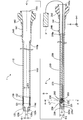
- FIG. 1 is an explanatory diagram illustrating the configuration of the light irradiation system of the first embodiment.
- the light irradiation system is used by inserting it into a biological lumen such as a vascular system, a lymph gland system, a biliary system, a urinary tract system, an airway system, a digestive system, a secretory gland and a reproductive organ.
- the light irradiation system is a system that irradiates light transmitted from the lumen of a living body toward a living tissue through an optical fiber.
- the light irradiation system can be used in, for example, PDT (Photodynamic Therapy) and NIR-PIT (Near-infrared photoimmunotherapy).
- the light irradiation system includes a catheter 1 and a light irradiation device 2 that is inserted into and used in the catheter 1. In FIG. 1, the catheter 1 and the light irradiation device 2 are shown separately.
- FIG. 1 the axis passing through the center of the catheter 1 and the axis passing through the center of the light irradiation device 2 are represented by axis lines O (dashed-dotted line), respectively.
- axis lines O dashed-dotted line
- FIG. 1 shows XYZ axes that are orthogonal to each other.
- the X-axis corresponds to the long axis direction (axis O direction) of the catheter 1 and the light irradiation device 2
- the Y-axis corresponds to the height direction of the catheter 1 and the light irradiation device 2
- the Z-axis corresponds to the catheter 1 and the light irradiation device.
- the left side (-X-axis direction) of FIG. 1 is referred to as the catheter 1, the light irradiation device 2, and the "tip side" of each component
- the right side (+ X-axis direction) of FIG. 1 is referred to as the catheter 1, the light irradiation device 2.
- the "base end side" of each component is referred to as the catheter 1 and the light irradiation device 2.
- the end portion located on the distal end side is referred to as a "tip”, and the distal end and its vicinity are referred to as a "tip portion”.
- the end portion located on the proximal end side is referred to as a "base end”, and the proximal end and its vicinity are referred to as a "base end portion”.
- the distal end side corresponds to the "distal side” inserted into the living body, and the proximal end side corresponds to the "proximal side” operated by a surgeon such as a doctor.
- the catheter 1 has a long tube shape and includes a shaft 110, a tip tip 120, and a connector 140.
- the shaft 110 is an elongated member extending along the axis O.
- the shaft 110 has a hollow substantially cylindrical shape (tube shape) in which both ends of the tip portion 110d and the base end portion 110p are open.
- the shaft 110 has a lumen 110L inside.
- the lumen 110L functions as a guide wire lumen for inserting the guide wire through the catheter 1 at the time of delivery of the catheter 1.
- the lumen 110L functions as a device lumen for inserting the light irradiation device 2 through the catheter 1 after the delivery of the catheter 1. In this way, the diameter of the catheter 1 can be reduced by using both the guide wire lumen and the device lumen as a single lumen.
- the outer diameter, inner diameter and length of the shaft 110 can be arbitrarily determined.
- the tip tip 120 is a member that is joined to the tip of the shaft 110 and advances in the lumen of the living body ahead of other members. As shown in FIG. 1, the tip tip 120 has an outer shape whose diameter is reduced from the proximal end side to the distal end side in order to facilitate the progress of the catheter 1 in the living lumen.
- a through hole 120h is formed in a substantially central portion of the tip tip 120 so as to penetrate the tip tip 120 in the O-axis direction.
- the opening diameter ⁇ 1 of the through hole 120h is smaller than the inner diameter ⁇ 2 of the lumen 110L of the shaft 110. Therefore, as shown in FIG.
- a step is formed due to the inner surface 120i of the tip tip 120 protruding.
- the opening 120o of the tip tip 120 communicates with the through hole 120h and is used when inserting a guide wire (not shown) into the catheter 1.
- the outer diameter and length of the tip tip 120 can be arbitrarily determined.
- the connector 140 is a member that is arranged on the proximal end side of the catheter 1 and is gripped by the operator.
- the connector 140 includes a substantially cylindrical connecting portion 141 and a pair of blades 142.
- the base end portion 110p of the shaft 110 is joined to the tip end portion of the connecting portion 141, and the blade 142 is joined to the base end portion.
- the blade 142 may have a structure integrated with the connector 140.
- the opening 140o of the connector 140 leads to the lumen 110L via the inside of the connector 140, and is used when inserting the light irradiation device 2 into the catheter 1.
- the outer diameter, inner diameter and length of the connecting portion 141 and the shape of the blade 142 can be arbitrarily determined.
- the shaft 110 of the catheter 1 is further provided with a light transmitting portion 139 and first marker portions 131 and 132.
- the light transmitting portion 139 transmits the light inside the shaft 110 to the outside.
- the light transmitting portion 139 is a hollow member having a substantially cylindrical shape, has an outer diameter substantially the same as the outer diameter of the shaft 110, and has an inner diameter substantially the same as the inner diameter ⁇ 2 of the lumen 110L of the shaft 110.
- the light transmitting portion 139 is provided in the entire circumferential direction, and transmits the light inside the shaft 110 to the outside in the entire circumferential direction.
- the light transmitting portion 139 is joined to the shaft 110 at the proximal end side and the distal end side, respectively.
- the light transmitting portion 139 can be formed of a transparent resin material having light transmitting property, for example, acrylic resin, polyethylene terephthalate, polyvinyl chloride, or the like.
- the first marker portions 131 and 132 function as markers indicating the positions of the light transmitting portions 139.
- the first marker portion 131 is provided close to the tip portion of the light transmitting portion 139, and functions as a mark indicating the position of the tip portion of the light transmitting portion 139.
- the first marker portion 132 is provided close to the base end portion of the light transmitting portion 139, and functions as a mark indicating the position of the base end portion of the light transmitting portion 139.
- the first marker portions 131 and 132 are hollow members having a substantially cylindrical shape, respectively. In the example of FIG. 1, the first marker portions 131 and 132 are respectively arranged in recesses formed on the outer surface of the shaft 110 and are joined to the outer surface of the shaft 110.
- the first marker portions 131 and 132 are embedded in the outer surface of the shaft 110 so as to surround the circumferential direction of the shaft 110, respectively.
- the first marker portions 131 and 132 may be provided so as to project from the outer surface of the shaft 110 by being joined to the outer surface of the shaft 110 having no recess. At least one of the first marker portions 131 and 132 may be omitted.
- the light irradiation device 2 has a long outer shape, and includes a shaft 210, a tip tip 220, a connector 240, an optical fiber 250, and a holding member 260.
- the shaft 210 is an elongated member extending along the axis O.
- the shaft 210 has a hollow substantially cylindrical shape (tube shape) in which both ends of the tip portion 210d and the base end portion 210p are open.
- An opening for exposing the tip of the optical fiber 250 is formed on the outer peripheral surface of the shaft 210 on the tip end side (described later in FIG. 3).
- An optical fiber 250 and a holding member 260 are housed inside (inside) the shaft 210. Further, the void portion of the inside of the shaft 210 except for the optical fiber 250 and the holding member 260 is filled with the resin member 270.
- the shaft 210 corresponds to a "hollow shaft”.
- the tip tip 220 is a member that is joined to the tip 210d of the shaft 210 and advances the lumen 110L of the catheter 1 ahead of other members.
- the tip tip 220 is a substantially cylindrical member extending in the long axis direction of the light irradiation device 2.
- the outer diameter ⁇ 3 of the tip tip 220 and the shaft 210 (in other words, the outer diameter ⁇ 3 of the light irradiation device 2) is larger than the opening diameter ⁇ 1 of the through hole 120h of the catheter 1, and the shaft 110 of the catheter 1
- the inner diameter of the light transmitting portion 139 is smaller than the inner diameter ⁇ 2 ( ⁇ 1 ⁇ 3 ⁇ 2).
- the connector 240 is a member that is arranged on the base end side of the light irradiation device 2 and is gripped by the operator.
- the connector 240 includes a substantially cylindrical connecting portion 241 and a pair of blades 242.
- the base end portion 210p of the shaft 210 is joined to the tip end portion of the connecting portion 241 and the blade 242 is joined to the base end portion of the connecting portion 241.
- the blade 242 may have a structure integrated with the connector 240.
- FIG. 2 is an explanatory view illustrating the cross-sectional configuration along the line AA of FIG.
- the XYZ axes shown in FIG. 2 correspond to the XYZ axes of FIG. 1, respectively.
- the optical fiber 250 includes a core 250c extending in the long axis direction (axis O direction) of the light irradiation device 2 and a clad 250cl covering the outer peripheral surface (outer surface) of the core 250c.
- the core 250c is located substantially in the center of the clad 250cl and has a higher refractive index than the clad 250cl.
- the clad 250cl has a uniform refractive index.
- the optical fiber 250 transmits light by total internal reflection of light utilizing the difference in refractive index between the core 250c and the clad 250cl.
- the clad 250cl corresponds to a "coating layer” that covers the core 250c and also corresponds to a "member that constitutes the outer surface of the optical fiber 250".
- the optical fiber 250 of this embodiment is a plastic optical fiber in which both the core 250c and the clad 250cl are made of resin.
- the core 250c can be formed of, for example, a polymethylmethacrylate resin (PMMA), polystyrene, polycarbonate, a weighted hydrogenated polymer, a fluorine-based polymer, a silicon-based polymer, a norbornene-based polymer, or the like.
- PMMA polymethylmethacrylate resin
- the core 250c is classified into a single mode and a multi-mode according to the number of modes in which light propagates, and either of them may be used in the present embodiment.
- the multi-mode core 250c it is classified into a step index and a graded index according to the refractive index distribution, but in this embodiment, either of them may be used.
- the clad 250cl can be formed of, for example, a fluorine-based polymer.
- the optical fiber 250 a quartz glass optical fiber or a multi-component glass optical fiber may be used instead of the plastic optical fiber.
- the length of the optical fiber 250 in the major axis direction can be arbitrarily determined.
- the tip end side of the optical fiber 250 is inserted inside the shaft 210 and fixed by the resin member 270.
- the base end side of the optical fiber 250 passes through the inside of the connector 240 and is pulled out to the outside.
- the base end portion of the optical fiber 250 is directly connected to the light source 3 via a connector (not shown) or indirectly via another optical fiber.
- the light source 3 is, for example, a laser light generator that generates laser light of an arbitrary wavelength.
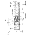
- FIG. 3 is a top view of the light irradiation device 2 as seen from the direction B of FIG.
- a curved portion 251 in which the optical fiber 250 is curved in the + Y axis direction is formed at the tip of the optical fiber 250.
- the tip (tip surface) of the optical fiber 250 is arranged so as to be exposed on the outer peripheral surface (outer surface) of the shaft 210.
- the clad 250cl is removed to expose the core 250c. From the exposed core 250c, the laser light LT generated by the light source 3 and transmitted via the optical fiber 250 is irradiated.
- the core 250c exposed at the tip of the optical fiber 250 functions as a light irradiation unit 239 that irradiates the light LT to the outside.
- the tip of the optical fiber 250 that irradiates the laser beam LT intersects the long axis direction (axis O direction) of the light irradiation device 2 by the curved portion 251 of the optical fiber 250. Is aimed at.
- the light LT is irradiated from the core 250c (light irradiation unit 239) exposed at the tip of the optical fiber 250 toward one direction on the side surface of the light irradiation device 2.
- the core 250c is subjected to well-known processing (for example, processing for cutting the tip surface diagonally, processing for forming notches, sandblasting, chemical treatment). You may. Further, a resin body or a light reflection mirror for transmitting, refracting, and amplifying the laser beam LT may be provided at or near the tip of the core 250c.
- the resin body can be formed, for example, by applying it to an acrylic ultraviolet curable resin in which fine quartz powder is dispersed and curing it with ultraviolet light.
- the holding member 260 is a member that holds the shape (curved shape) of the curved portion 251 of the optical fiber 250.
- the holding member 260 is arranged inside the shaft 210 and at the position of the curved portion 251 of the optical fiber 250 (FIG. 1). Further, the holding member 260 is arranged so as to cover the entire outer peripheral surface of the curved portion 251 of the optical fiber 250 (FIG. 2).
- the holding member 260 is made of a light-transmitting resin.
- the light-transmitting resin means a resin that is transparent or translucent and has a property of transmitting light.
- any resin such as an epoxy resin filled with an inorganic powder can be used.
- the light transmissive resin used for the holding member 260 preferably has a high light transmissivity in the wavelength range (for example, 650 nm to 700 nm) used in PDT and NIR-PIT as compared with other wavelength ranges.
- the holding member 260 may be formed by mixing a plurality of different types of light-transmitting resins.
- the refractive index R6 of the holding member 260 is smaller than the refractive index R5 of the member (that is, the clad 250cl) constituting the outer surface of the optical fiber 250 (R6 ⁇ R5).
- the refractive index R7 of the resin member 270 is smaller than the refractive index R6 of the holding member 260 (R7 ⁇ R6). That is, the relationship between the refractive index R5 of the clad 250cl, the refractive index R6 of the holding member 260, and the refractive index R7 of the resin member 270 is “R7 ⁇ R6 ⁇ R5”.
- Representative values such as catalog values can be used for the refractive index R5 of the clad 250cl, the refractive index R6 of the holding member 260, and the refractive index R7 of the resin member 270.
- the first member and the second member having different refractive indexes are arranged adjacent to each other.
- the light traveling from the first member to the second member has a larger difference in refractive index between the first member and the second member, the more the boundary surface between the first member and the second member. It becomes easy to totally reflect (that is, it does not proceed to the second member).
- the smaller the difference in the refractive index between the first member and the second member the easier it is to proceed from the first member to the second member while refracting at the boundary surface between the first member and the second member.
- the refractive index R6 of the holding member 260 is smaller than the refractive index R5 of the clad 250cl forming the outer surface of the optical fiber 250 (R6 ⁇ R5). Therefore, as compared with the case where the shape of the curved portion 251 is held by using, for example, a holding member having a refractive index similar to that of the clad 250cl or a refractive index higher than the refractive index of the clad 250cl.
- the light inside the optical fiber 250 can be reflected at the boundary between the clad 250cl and the holding member 260. Therefore, the light leaking through the holding member 260 can be reduced.
- the refractive index R7 of the resin member 270 is smaller than the refractive index R6 of the holding member 260 (R7 ⁇ R6). Therefore, when compared with the resin member 270 and the holding member 260, the difference in the refractive index between the resin member 270 and the clad 250cl is larger than the difference in the refractive index between the holding member 260 and the clad 250cl. Therefore, the light leaking through the resin member 270 can be reduced.
- the optical fiber 250 is composed of only the core 250c and does not have to have a coating layer such as a clad 250cl.
- the core 250c corresponds to "a member constituting the outer surface of the optical fiber 250".
- the refractive index R6 of the holding member 260 is smaller than the refractive index R51 of the core 250c (R6 ⁇ R51).
- the optical fiber 250 may further include a cover that covers the outer peripheral surface of the clad 250 cl.
- the clad 250cl and the cover correspond to the "coating layer” that covers the core 250c, and the cover corresponds to the "member that constitutes the outer surface of the optical fiber 250".
- the refractive index R6 of the holding member 260 is smaller than the refractive index R52 of the cover (R6 ⁇ R52). Further, when the cover is composed of a plurality of layers, the outermost cover corresponds to "a member constituting the outer surface of the optical fiber 250". At this time, the refractive index R6 of the holding member 260 is smaller than the refractive index R53 of the cover arranged on the outermost side (R6 ⁇ R53).
- the shaft 210 of the light irradiation device 2 is further provided with second marker portions 231,232.
- the second marker units 231 and 232 function as markers indicating the position of the light irradiation unit 239 (that is, the tip of the optical fiber 250).
- the second marker unit 231 is provided close to the tip end side of the light irradiation unit 239, and functions as a mark indicating the position of the tip end side of the light irradiation unit 239.
- the second marker unit 232 is provided close to the base end side of the light irradiation unit 239, and functions as a mark indicating the position of the base end side of the light irradiation unit 239.
- the second marker portions 231 and 232 are hollow members having a substantially cylindrical shape, respectively.
- the second marker portions 231 and 232 are respectively arranged in the recesses formed on the outer surface of the shaft 210 and are joined to the outer surface of the shaft 210.
- the second marker portions 231 and 232 are embedded in the outer surface of the shaft 210 so as to surround the circumferential direction of the shaft 210, respectively.
- the second marker portions 231 and 232 may be provided so as to project from the outer surface of the shaft 210 by being joined to the outer surface of the shaft 210 having no recess. At least one of the second marker portions 231,232 may be omitted.
- the first marker portions 131 and 132 of the catheter 1 and the second marker portions 231 and 232 of the light irradiation device 2 can be formed of a resin material or a metal material having radiation opacity.
- a resin material when a resin material is used, it can be formed by mixing a radiation-impermeable material such as bismuth trioxide, tungsten, or barium sulfate with a polyamide resin, a polyolefin resin, a polyester resin, a polyurethane resin, a silicon resin, a fluororesin, or the like.
- a metal material when a metal material is used, it can be formed of a radiation-impermeable material such as gold, platinum, tungsten, or an alloy containing these elements (for example, platinum-nickel alloy).
- the shaft 110 of the catheter 1, the shaft 210 of the light irradiation device 2, and the resin member 270 of the light irradiation device 2 preferably have antithrombotic properties, flexibility, and biocompatibility, and may be made of a resin material or a metal material. Can be formed.
- the resin material for example, polyamide resin, polyolefin resin, polyester resin, polyurethane resin, silicon resin, fluororesin and the like can be adopted.
- the metal material for example, stainless steel such as SUS304, nickel titanium alloy, cobalt chromium alloy, tungsten steel and the like can be adopted.
- the shaft 110 and the shaft 210 may be formed into a bonded structure in which a plurality of the above-mentioned materials are combined.
- the tip 120 of the catheter 1 and the tip 220 of the light irradiation device 2 are preferably flexible, and can be formed of, for example, a resin material such as polyurethane or polyurethane elastomer.
- the connector 140 of the catheter 1 and the connector 240 of the light irradiation device 2 can be formed of a resin material such as polyamide, polypropylene, polycarbonate, polyacetal, and polyether sulfone.
- FIG. 4 is an explanatory diagram illustrating the usage state of the light irradiation system.
- a method of using the light irradiation system will be described with reference to FIGS. 1 and 4.
- the operator inserts a guide wire into the lumen of the living body.
- the operator inserts the proximal end side of the guide wire from the opening 120o of the tip tip 120 of the catheter 1 shown in FIG. 1 into the lumen 110L and projects it from the opening 140o of the connector 140.
- the operator pushes the catheter 1 into the lumen of the living body along the guide wire, and the light transmitting portion 139 of the catheter 1 is directed to the target site of light irradiation (for example, in the case of NIR-PIT, of cancer cells).
- the target site of light irradiation for example, in the case of NIR-PIT, of cancer cells.
- the operator can easily deliver the catheter 1 to the target site in the living lumen.
- the operator positions the catheter 1 in the living lumen while confirming the positions of the first marker portions 131 and 132 arranged in the vicinity of the light transmitting portion 139 in the X-ray image. be able to. The surgeon then removes the guide wire from the catheter 1.
- the operator inserts the light irradiation device 2 through the opening 140o of the connector 140 of the catheter 1.
- the operator pushes the light irradiation device 2 toward the tip end side of the catheter 1 along the lumen 110L of the catheter 1.
- the catheter 1 can be formed.
- the tip surface 220e of the light irradiation device 2 abuts on the inner surface 120i of the tip chip 120, so that the light irradiation device 2 can be prevented from coming off to the tip side (FIG. 4).
- the operator confirms the positional relationship between the first marker units 131 and 132 and the second marker units 231,232 in the X-ray image, thereby confirming the positional relationship between the light transmitting unit 139 and the light irradiation unit 239 (optical fiber). Align the position with the tip of 250 in the O direction (X-axis direction). As a result, the laser light LT emitted from the light irradiation unit 239 (the tip of the optical fiber 250) can be transmitted to the light transmission unit 139 of the catheter 1 and emitted to the external living tissue.
- the light transmitting portion 139 is provided in the entire circumferential direction.
- the operator only needs to align the light transmitting portion 139 and the light irradiation portion 239 in the axis O direction (X-axis direction), and the light transmitting portion in the circumferential direction. It is not necessary to align the 139 with the light irradiation unit 239.
- the tip of the optical fiber 250 is directed by the curved portion 251 in the direction intersecting the long axis direction (axis O direction) of the light irradiation device 2.
- the shape of the curved portion 251 is held by the holding member 260 (FIG. 4). Therefore, for example, the configuration of the light irradiation device 2 is compared with a configuration in which the tip of the optical fiber is directed in a direction intersecting the long axis direction of the light irradiation device by moving the optical fiber using a guide means. Since it can be simplified, the diameter of the light irradiation device 2 can be reduced.
- the refractive index R6 of the holding member 260 is smaller than the refractive index R5 of the clad 250cl (a member constituting the outer surface of the optical fiber 250). Therefore, as described in FIG. 2, for example, the shape of the curved portion 251 is maintained by using a holding member having a refractive index equal to or higher than the refractive index of the clad 250cl. Compared with the case, the light inside the optical fiber 250 can be reflected at the boundary between the clad 250cl and the holding member 260. As a result, according to the light irradiation device 2 of the first embodiment, the light leaking from the inside of the optical fiber 250 can be reduced.
- the resin member 270 is filled in the base end side of the shaft 210 (hollow shaft) with respect to the holding member 260. Therefore, the long shape of the light irradiation device 2 can be easily maintained. Further, the refractive index R7 of the resin member 270 is smaller than the refractive index R6 of the holding member 260. Therefore, as described with reference to FIG. 2, the light leaking through the resin member 270 can be reduced.
- the light irradiation device 2 and the light transmission unit 139 that transmits the internal light LT to the outside are provided at positions corresponding to the tip of the optical fiber 250 (that is, the light irradiation unit 239).
- the catheter 1 to be provided and the catheter 1 to be provided are individually provided. Therefore, the degree of freedom in device design can be improved, and the range of procedures can be expanded.
- FIG. 5 is an explanatory diagram illustrating the configuration of the light irradiation device 2A of the second embodiment.
- FIG. 6 is an explanatory view illustrating the cross-sectional configuration taken along the line CC of FIG.
- the light irradiation system of the second embodiment includes the catheter 1 described in the first embodiment and the light irradiation device 2A shown in FIGS. 5 and 6.
- the light irradiation device 2A includes a holding member 260A instead of the holding member 260, and does not include a resin member 270.
- the holding member 260A is arranged adjacent to the inner peripheral side of the curved portion 251 of the optical fiber 250.
- the inner peripheral side of the curved portion 251 means the inside of the portion having a curved shape in the outer peripheral surface of the optical fiber 250, and in the examples of FIGS. 5 and 6, it means the + Y-axis direction side.
- a resin member 270 is arranged on the outer peripheral side (FIG. 5, FIG. 6: -Y-axis direction side) of the curved portion 251 of the optical fiber 250.
- the magnitude relation of the refractive index of the clad 250cl, the holding member 260A, and the resin member 270 is the same as that of the first embodiment.
- the configuration of the holding member 260A of the light irradiation device 2A can be changed in various ways, and the holding member 260A may be arranged only on the inner peripheral side of the curved portion 251 of the optical fiber 250.
- the holding member 260A is arranged on the inner peripheral side of the curved portion 251 over a range of about 170 degrees in the circumferential direction, but the range in which the holding member 260A is provided is arbitrarily changed. It is possible, for example, 30 degrees, 90 degrees, or 270 degrees.
- the outer peripheral side of the curved portion 251 is filled with the resin member 270, but the outer peripheral side of the curved portion 251 is not filled with the resin member 270. There may be.
- the light irradiation system of the second embodiment as described above can also achieve the same effect as that of the first embodiment described above.
- the shape of the curved portion 251 of the optical fiber 250 can be maintained at least from the inner peripheral side of the curved portion 251.
- the inner peripheral side of the curved portion 251 is the direction in which the tip of the optical fiber 250 faces (that is, the direction in which the light irradiation portion 239 is provided), and the direction in which the optical LT is irradiated from the optical fiber 250.
- all substances including the substance forming the holding member 260A have a higher refractive index than air.
- the holding member 260A and the resin member 270 are not arranged and are left as a gap on the outer peripheral side of the curved portion 251 (the direction in which light is not irradiated from the optical fiber 250). As a result, leakage of light in a direction in which light is not irradiated from the optical fiber 250 can be further suppressed.
- FIG. 7 is an explanatory diagram illustrating the configuration of the light irradiation device 2B of the third embodiment.
- FIG. 8 is an explanatory view illustrating the cross-sectional configuration along the DD line of FIG.
- the light irradiation system of the third embodiment includes the catheter 1 described in the first embodiment and the light irradiation device 2B shown in FIGS. 7 and 8.
- the light irradiation device 2B includes a holding member 260B instead of the holding member 260.
- the holding member 260B includes an inner holding member 261 and an outer holding member 262.
- the inner holding member 261 is arranged adjacent to the inner peripheral side of the curved portion 251 of the optical fiber 250.
- the outer holding member 262 is arranged adjacent to the outer peripheral side of the curved portion 251 of the optical fiber 250.
- the inner holding member 261 is arranged on the inner peripheral side of the curved portion 251 over a range of about 170 degrees in the circumferential direction, and the outer holding member 262 is the outer circumference of the curved portion 251. On the side, it is arranged over the residual range in the circumferential direction (range of about 190 degrees).
- the range in which the inner holding member 261 is arranged and the range in which the outer holding member 262 is arranged in the circumferential direction can be arbitrarily changed.
- the inner holding member 261 and the outer holding member 262 are formed of different light-transmitting resins.
- the refractive index R62 of the outer holding member 262 is smaller than the refractive index R61 of the inner holding member 261 (R62 ⁇ R61).
- the refractive indexes R61 and R62 of the holding member 260B are both from the refractive index R5 of the clad 250cl constituting the outer surface of the optical fiber 250. Is also small. Therefore, the magnitude relationship of the refractive index is R62 ⁇ R61 ⁇ R5.
- the configuration of the holding member 260B of the light irradiation device 2B can be changed in various ways, and the holding member 260B has an inner holding member 261 and an outer holding member 262 formed of different light-transmitting resins. It may be included.
- the light irradiation system of the third embodiment as described above can also achieve the same effect as that of the first embodiment described above.
- the shape (curved shape) of the curved portion 251 can be firmly held from different directions of the inner peripheral side of the curved portion 251 and the outer peripheral side of the curved portion 251. ..
- the refractive index R62 of the outer holding member 262 arranged on the outer peripheral side of the curved portion 251 is inside the curved portion 251. It is smaller than the refractive index R61 of the inner holding member 261 arranged on the circumferential side (the side irradiated with the light LT, in the + Y-axis direction in the example of FIG. 7).
- the difference in the refractive index between the outer holding member 262 and the clad 250cl is larger than the difference in the refractive index between the inner holding member 261 and the clad 250cl. Become. Therefore, the leakage of light from the outer holding member 262 provided in the direction in which light is not emitted from the optical fiber 250 is regarded as the leakage of light from the inner holding member 261 provided in the direction in which light is irradiated from the optical fiber 250. In comparison, it can be further suppressed.
- the magnitude relationship between the refractive index R61 of the inner holding member 261 and the refractive index R62 of the outer holding member 262 may be reversed (R61 ⁇ R62). Further, the refractive index R61 of the inner holding member 261 and the refractive index R62 of the outer holding member 262 may be substantially the same. Even in this way, the same effect as that of the first embodiment can be obtained, and the shape of the curved portion 251 is firmly formed from different directions from the inner peripheral side of the curved portion 251 and the outer peripheral side of the curved portion 251. Can be retained.
- FIG. 9 is an explanatory diagram illustrating the configuration of the light irradiation device 2C of the fourth embodiment.
- FIG. 10 is an explanatory view illustrating the cross-sectional structure taken along the line EE of FIG.
- the light irradiation system of the fourth embodiment includes the catheter 1 described in the first embodiment and the light irradiation device 2C shown in FIGS. 9 and 10.
- the light irradiation device 2C includes a holding member 260C instead of the holding member 260.
- the holding member 260C includes an inner holding member 261C and an outer holding member 262C.
- the inner holding member 261C is arranged on the inner peripheral side of the curved portion 251 of the optical fiber 250 over a range of about 100 degrees in the circumferential direction.
- the outer holding member 262C is arranged on the outer peripheral side of the curved portion 251 of the optical fiber 250 over a range of about 100 degrees in the circumferential direction.
- the residual portion in the circumferential direction is filled with the resin member 270, but the residual portion in the circumferential direction of the curved portion 251 is not filled with the resin member 270, for example, in a gap. There may be.
- the materials of the inner holding member 261C and the outer holding member 262C are the same as those in the third embodiment.
- the magnitude relationship of the refractive indexes of the inner holding member 261C, the outer holding member 262C, and the clad 250cl is the same as that of the third embodiment (R62 ⁇ R61 ⁇ R5).
- the configuration of the holding member 260C of the light irradiation device 2C can be changed in various ways, and the holding member 260C includes an inner holding member 261C arranged apart from each other in the circumferential direction and an outer holding member 262C. You may be.
- the light irradiation system of the fourth embodiment as described above can also achieve the same effects as those of the first and fourth embodiments described above.
- FIG. 11 is an explanatory diagram illustrating the configuration of the light irradiation device 2D according to the fifth embodiment.
- the light irradiation system of the fifth embodiment includes the catheter 1 described in the first embodiment and the light irradiation device 2D shown in FIG.
- the light irradiation device 2D includes a holding member 260D instead of the holding member 260.
- the holding member 260D includes a first inner holding member 261D, a second inner holding member 263D, and an outer holding member 262D.
- the first inner holding member 261D is arranged on the inner peripheral side of the curved portion 251 of the optical fiber 250 and on the tip end side (-X-axis direction) of the light irradiation device 2D.
- the second inner holding member 263D is arranged on the inner peripheral side of the curved portion 251 of the optical fiber 250 and on the proximal end side (+ X-axis direction) of the light irradiation device 2D.
- the first inner holding member 261D and the second inner holding member 263D correspond to "inner holding members".
- the outer holding member 262D is arranged adjacent to the outer peripheral side of the curved portion 251 of the optical fiber 250.
- the circumferential range in which the first inner holding member 261D, the second inner holding member 263D, and the outer holding member 262D are arranged can be arbitrarily determined.
- the first inner holding member 261D and the second inner holding member 263D are arranged in the range of a predetermined angle in the circumferential direction
- the outer holding member 262D is arranged in the range of the residual in the circumferential direction. May be good.
- the first inner holding member 261D and the second inner holding member 263D are arranged in a range of a predetermined angle in the circumferential direction
- the outer holding member 262D is arranged in a range of a predetermined angle in a different circumferential direction.
- the resin member 270 may be filled in the residual range in the circumferential direction.
- the first inner holding member 261D, the second inner holding member 263D, and the outer holding member 262D are formed of different light-transmitting resins.
- the refractive index R63 of the second inner holding member 263D is smaller than the refractive index R61 of the first inner holding member 261D and larger than the outer holding member 262D (R62 ⁇ R63 ⁇ R61).
- the refractive indexes R61, R63, and R62 of the holding member 260D are all of the optical fiber 250. It is smaller than the refractive index R5 of the clad 250 cl constituting the outer surface. Therefore, the magnitude relationship of the refractive index is R62 ⁇ R63 ⁇ R61 ⁇ R5.
- the configuration of the holding member 260D of the light irradiation device 2D can be changed in various ways, and the inner holding member of the holding member 260D includes the first inner holding member 261D formed of different light transmissive resins and the first inner holding member 261D.
- the second inner holding member 263D may be included.
- three or more inner holding members may be provided on the inner peripheral side of the curved portion 251 of the optical fiber 250.
- the light irradiation system of the fifth embodiment as described above can also achieve the same effect as that of the first embodiment described above.
- the inner holding member includes a first inner holding member 261D arranged on the tip end side and a second inner holding member 263D arranged on the proximal end side. Since it is contained, the degree of light leakage can be changed by controlling the refractive indexes R61 and R63 of the first and second inner holding members 261D and 263D. Further, the refractive index R63 of the second inner holding member 263D is smaller than the refractive index R61 of the first inner holding member 261D and larger than the refractive index R62 of the outer holding member 262D.
- the leakage of light from the outer holding member 262D provided in the direction in which the light is not emitted from the optical fiber 250 is prevented from leaking from the first and second inner holding members 261D provided in the direction in which the light is irradiated from the optical fiber 250.
- the leakage of light from 263D it can be further suppressed.
- the leakage of light from the second inner holding member 263D arranged on the proximal end side can be further suppressed as compared with the leakage of light from the first inner holding member 261D arranged on the distal end side.
- FIG. 12 is an explanatory diagram illustrating the configuration of the light irradiation device 2E of the sixth embodiment.
- the light irradiation system of the sixth embodiment includes the catheter 1 described in the first embodiment and the light irradiation device 2E shown in FIG.
- the light irradiation device 2E does not include the resin member 270 described in the first embodiment, and the portion inside the shaft 210 where the optical fiber 250 and the holding member 260 are not housed is a gap.
- the configuration of the light irradiation device 2E can be changed in various ways, and the resin member 270 may not be provided, or may be provided with another reinforcing member in place of the resin member 270.
- the other reinforcing member for example, a braided body or a coil body can be adopted.
- a reinforcing member may be arranged inside the shaft 210. It may be embedded in the thick portion of the shaft 210.
- the light irradiation system of the sixth embodiment as described above can also achieve the same effect as that of the first embodiment described above.
- FIG. 13 is an explanatory diagram illustrating the configuration of the light irradiation device 2F of the seventh embodiment.
- the light irradiation system of the seventh embodiment includes the catheter 1 described in the first embodiment and the light irradiation device 2F shown in FIG.
- the light irradiation device 2F is not provided with the tip 220, is provided with an optical fiber 250F instead of the optical fiber 250, and is provided with a holding member 260F instead of the holding member 260.
- the holding member 260F covers the periphery of the curved portion 251 protruding from the shaft 210. In other words, the holding member 260F covers the entire surface of the curved portion 251 protruding from the shaft 210 in the circumferential direction.
- the holding member 260F has a shape in which the diameter is reduced from the base end side toward the tip end side and the tip end portion is rounded.
- the holding member 260F is provided along the curved portion 251 curved in the + Y axis direction, the reduced diameter shape of the holding member 260 is asymmetric with respect to the axis O in the cross section shown in FIG.
- the maximum outer diameter of the holding member 260F is the same as the outer diameter ⁇ 3 of the shaft 210 (in other words, the outer diameter ⁇ 3 of the light irradiation device 2F).
- the material and refractive index of the holding member 260F are the same as those in the first embodiment.
- the configuration of the light irradiation device 2F can be variously changed, and the curved portion 251 of the optical fiber 250F protrudes from the shaft 210, and further includes a holding member 260F that covers the periphery of the protruding curved portion 251. May be done.
- the shape of the holding member 260F can be arbitrarily changed.
- the holding member 260F may cover at least a part of the curved portion 251 protruding from the shaft 210, not the entire circumferential direction.
- the light irradiation system of the seventh embodiment as described above can also achieve the same effect as that of the first embodiment described above.
- the tip of the optical fiber 250F is formed by projecting a part of the curved portion 251 on the tip end side, that is, the tip of the optical fiber 250F from the tip of the shaft 210 (hollow shaft). It is possible to prevent the light LT emitted from the shaft 210 from being blocked by the shaft 210. Further, since the holding member 260F covers the periphery of the protruding curved portion 251, the periphery of the protruding curved portion 251 can be protected.
- FIG. 14 is an explanatory diagram illustrating the configuration of the light irradiation device 2G according to the eighth embodiment.
- the light irradiation system of the eighth embodiment includes the catheter 1 described in the first embodiment and the light irradiation device 2G shown in FIG.
- the light irradiation device 2G includes a holding member 260G having a shape different from that of the seventh embodiment in a configuration in which the curved portion 251 of the optical fiber 250F described in the seventh embodiment protrudes from the shaft 210.
- the holding member 260G covers the periphery of the curved portion 251 protruding from the shaft 210 (the entire surface in the circumferential direction).
- the holding member 260G is a substantially cylindrical member having a substantially constant outer diameter, and the outer diameter of the holding member 260G is substantially the same as the outer diameter ⁇ 3 of the shaft 210.
- the holding member 260G is joined to the tip of the shaft 210. Any bonding agent such as an epoxy adhesive can be used for bonding.
- Any bonding agent such as an epoxy adhesive can be used for bonding.
- the configuration of the light irradiation device 2G can be changed in various ways, and the holding member 260G having a shape different from that of the seventh embodiment may be provided.
- the light irradiation system of the eighth embodiment as described above can also achieve the same effect as that of the first and seventh embodiments described above.
- FIG. 15 is an explanatory diagram illustrating the configuration of the light irradiation device 2H of the ninth embodiment.
- the light irradiation system of the ninth embodiment includes the catheter 1 described in the first embodiment and the light irradiation device 2H shown in FIG.
- the light irradiation device 2H includes a holding member 260H having a shape different from that of the seventh embodiment in a configuration in which the curved portion 251 of the optical fiber 250F described in the seventh embodiment protrudes from the shaft 210.
- the holding member 260H includes a tip end side holding member 261H and a proximal end side holding member 262H.
- the tip side holding member 261H is arranged at the tip of the light irradiation device 2H, and covers the periphery of the tip side (the entire surface in the circumferential direction) of the curved portion 251 protruding from the shaft 210.
- the base end side holding member 262H is arranged between the tip end side holding member 261H and the shaft 210, and covers the periphery of the base end side (the entire surface in the circumferential direction) of the curved portion 251 protruding from the shaft 210. ing.
- the tip end side holding member 261H and the proximal end side holding member 262H are both substantially cylindrical members having a substantially constant outer diameter.
- Both the outer diameter of the tip end side holding member 261H and the outer diameter of the proximal end side holding member 262H are substantially the same as the outer diameter ⁇ 3 of the shaft 210.
- the configuration of the light irradiation device 2H can be changed in various ways, and the holding member 260H having a shape different from that of the seventh embodiment may be provided.
- the light irradiation system of the ninth embodiment as described above can also achieve the same effects as those of the first and seventh embodiments described above.
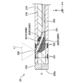
- FIG. 16 is an explanatory diagram illustrating the configuration of the light irradiation device 2I of the tenth embodiment.
- the light irradiation system of the tenth embodiment includes the catheter 1 described in the first embodiment and the light irradiation device 2I shown in FIG.
- the light irradiation device 2I includes a shaft 210I instead of the shaft 210, an optical fiber 250I instead of the optical fiber 250, and a light irradiation unit 239I instead of the light irradiation unit 239.
- the shaft 210I has a hollow substantially cylindrical shape in which both ends of the tip end portion and the base end portion are open. Unlike the shaft 210 of the first embodiment, the shaft 210I is not formed with an opening for exposing the tip of the optical fiber 250I. Further, in the shaft 210I, the portion where the tip of the optical fiber 250I abuts is formed of a light transmissive resin, and is configured to allow the laser beam LT to pass through. Similar to the optical fiber 250 of the first embodiment, the optical fiber 250I has a curved portion 251 formed at the tip of the optical fiber 250I in which the optical fiber 250I is curved in the + Y axis direction.
- the optical fiber 250I is arranged so that its tip (tip surface) is in contact with the inner peripheral surface of the shaft 210I.
- the light LT emitted from the core 250c exposed at the tip of the optical fiber 250I passes through the shaft 210I and is irradiated to the outside. Therefore, in the present embodiment, a part of the shaft 210I functions as the light irradiation unit 239I.
- the configuration of the light irradiation device 2I can be changed in various ways, and the tip of the optical fiber 250I does not have to be exposed on the outer peripheral surface of the shaft 210I.
- the optical LT may be transmitted by making the wall thickness of the portion of the shaft 210I that the tip of the optical fiber 250I abuts is thinner than that of the other portions.
- a resin body or a light reflection mirror for transmitting, refracting, and amplifying the optical LT may be provided on the portion of the shaft 210I where the tip of the optical fiber 250I abuts.
- the entire shaft 210I may be formed of a light-transmitting resin.
- the light irradiation system of the tenth embodiment as described above can also achieve the same effect as that of the first embodiment described above.
- FIG. 17 is an explanatory diagram illustrating the configuration of the light irradiation system of the eleventh embodiment.
- the light irradiation system of the eleventh embodiment includes the catheter 1 described in the first embodiment and the light irradiation device 2J shown in FIG.
- the light irradiation device 2J does not include the shaft 210, the tip tip 220, and the connector 240 described in the first embodiment, and is composed of an optical fiber 250J and a holding member 260J.
- the configuration of the optical fiber 250J is the same as that of the optical fiber 250 described in the first embodiment, and the configuration of the holding member 260J is the same as that of the holding member 260 described in the first embodiment.
- the configuration of the light irradiation device 2J can be changed in various ways, and it is not necessary to include at least a part of the shaft 210, the tip tip 220, and the connector 240.
- the light irradiation system of the eleventh embodiment as described above can also achieve the same effect as that of the first embodiment described above.
- the configuration of the light irradiation device 2J can be simplified, the light irradiation device 2J can be easily manufactured and the manufacturing cost of the light irradiation device 2J can be reduced. ..
- the diameter of the light irradiation device 2J can be reduced, it is possible to deliver the device from the forceps opening of a small-diameter endoscope such as an oral endoscope or a nasal endoscope.
- a reinforcing layer made of a braided body or a coil body may be embedded in the shaft 110 of the catheter 1 and the shaft 210 of the light irradiation device 2.
- the torque transmission property and the shape retention property of the catheter 1 and the light irradiation device 2 can be improved.
- the outer surface of the catheter 1 and the outer surface of the light irradiation device 2 may be coated with a hydrophilic or hydrophobic resin. In this way, the slipperiness of the catheter 1 in the living lumen can be improved. In addition, the slipperiness of the light irradiation device 2 in the lumen 110L of the catheter 1 can be improved.
- an antithrombotic material such as heparin may be coated on the outer surface of the catheter 1 or the outer surface of the light irradiation device 2. In this way, it is possible to suppress a decrease in laser output due to thrombus adhesion to the inner and outer surfaces of the catheter 1 and the outer surface of the light irradiation device 2 due to irradiation with emitted light (laser light) LT.
- the catheter 1 may be provided with an expansion portion that can be expanded in the radial direction (YZ direction).
- the expansion portion for example, a balloon made of a flexible thin film or a mesh body having a mesh of strands can be used.
- the extension portion may be provided on at least one of the tip end side of the light transmitting portion 139 and the proximal end side of the light transmitting portion 139 in the shaft 110. In this way, the catheter 1 can be fixed in the living lumen by expanding the dilated portion after positioning the catheter 1 in the living lumen. Further, if a balloon is used as the expansion portion, the blood flow at the light irradiation site can be blocked, so that the blockage of light due to the blood flow can be suppressed.
- the catheter 1 may be configured as a multi-lumen catheter having a plurality of lumens different from the lumen 110L.
- the light irradiation device 2 may be configured as a multi-lumen catheter having a separate lumen different from the lumen 210 L through which the first optical fiber 250 is inserted.
- the shaft 210 may be made of a hollow, substantially cylindrical member, and the tip tip 220 may be provided with a through hole extending along the axis O direction.
- the inner surface of the tip tip 120 of the catheter 1 and the outer surface of the tip tip 220 of the light irradiation device 2 may be formed of a magnetic material so as to attract each other.
- the light irradiation device 2 can be inserted into the catheter 1 and the state in which the tip tip 220 is pressed against the tip tip 120 can be easily maintained.
- the tip 120 of the tip of the catheter 1 may be omitted, and a configuration in which the tip of the shaft 110 is open may be adopted.
- the curved portion 251 for crossing the tip of the optical fiber 250 in the long axis direction of the light irradiation device 2 is not limited to the shape shown in the figure, and any shape can be adopted.
- the optical fiber 250 may have a separate curved portion different from the curved portion 251 for crossing the tip of the optical fiber 250 in the long axis direction of the light irradiation device 2.
- This curved portion may be provided, for example, on the proximal end side of the curved portion 251.
- the shape of the curved portion can be arbitrarily determined, and can be, for example, a spiral shape along the inner peripheral surface of the shaft 210, a wavy shape, or a bellows shape.
- the range of the outer holding member in the long axis direction (axis O direction) can be arbitrarily determined.
- the outer holding member arranged adjacent to the outer peripheral side of the curved portion 251 may be provided up to the tip of the shaft 210 (the boundary surface between the shaft 210 and the tip tip 220).
- the light irradiation device 2 does not include an inner holding member arranged adjacent to the inner peripheral side of the curved portion 251 but includes only an outer holding member arranged adjacent to the outer peripheral side of the curved portion 251. You may be.
- the outer holding member arranged adjacent to the outer peripheral side of the curved portion 251 the first outer holding member arranged on the tip side and the second outer holding member arranged on the proximal end side.
- An outer holding member may be provided.
- the outer holding member arranged adjacent to the outer peripheral side of the curved portion 251 may include three or more outer holding members.
- the configurations of the light transmitting unit 139 and the light irradiating unit 239, 239I can be changed in various ways.
- the light transmitting portion 139 and the first marker portions 131 and 132 may be integrally formed by forming the light transmitting portion 139 with a material having radiation opacity.
- the tip portion (light irradiation portion 239) of the clad 250cl with a material having radiation opacity are integrally formed. May be good.
- the light transmitting portion 139 may be formed by thinning a part of the shaft 110.
- at least one of the light transmitting portions 139 may be formed as a notch (through hole communicating inside and outside the shaft) formed in the shaft 110.
- the light transmitting portion 139 can be easily formed.
- the range of the axis O direction (X axis direction) and the range of the circumferential direction (YZ axis direction) in which the light transmitting portion 139 is provided can be arbitrarily changed.
- the light transmitting portion 139 may be provided in a wide range in the axis O direction.
- the catheter 1 may further be provided with a separate marker portion arranged at an arbitrary position, such as the distal end side of the light transmitting portion 139 or the proximal end side of the light transmitting portion 139.
- the light irradiation device 2 may further include a separate marker unit arranged at an arbitrary position such as the tip end side of the light irradiation unit 239 or the base end side of the light irradiation unit 239.
- the shape of the marker portion of the catheter 1 and the light irradiation device 2 can be arbitrarily determined, and may be a shape extending in the entire or a part of the circumferential direction (YZ direction) or a shape extending in the axis O direction (X-axis direction). , It may be a shape that surrounds the circumference of the shaft.
- the tip 120 of the catheter 1 and the tip 220 of the light irradiation device 2 may be configured as a marker portion.
- Inner holding member 261D First inner holding member 261H ... Tip side holding member 262,262C, 262D ... Outer holding member 262H ... Base end side holding member 263D ... Second inner Holding member 270 ... Resin member
Landscapes
- Health & Medical Sciences (AREA)
- Physics & Mathematics (AREA)
- Life Sciences & Earth Sciences (AREA)
- Biomedical Technology (AREA)
- Engineering & Computer Science (AREA)
- Optics & Photonics (AREA)
- Animal Behavior & Ethology (AREA)
- General Health & Medical Sciences (AREA)
- Nuclear Medicine, Radiotherapy & Molecular Imaging (AREA)
- Veterinary Medicine (AREA)
- Public Health (AREA)
- General Physics & Mathematics (AREA)
- Surgery (AREA)
- Radiology & Medical Imaging (AREA)
- Pathology (AREA)
- Astronomy & Astrophysics (AREA)
- Biophysics (AREA)
- Electromagnetism (AREA)
- Otolaryngology (AREA)
- Heart & Thoracic Surgery (AREA)
- Medical Informatics (AREA)
- Molecular Biology (AREA)
- Radiation-Therapy Devices (AREA)
- Laser Surgery Devices (AREA)
- Surgical Instruments (AREA)
Abstract
This light emitting device having a long shape is an optical fiber that emits light from the tip thereof, the light emitting device comprising: an optical fiber which has a curved section and in which the tip faces a direction crossing the longitudinal direction of the optical fiber due to the curved section; and a light-transmitting holding member that maintains the shape of the curved section of the optical fiber. The optical fiber has a core, or has a core and a plurality of cover layers, and the refractive index of the holding member is smaller than the refractive index of a member that constitutes the outer surface of the optical fiber.
Description
本発明は、光照射デバイス、及び、光照射システムに関する。
The present invention relates to a light irradiation device and a light irradiation system.
がん治療においては、外科的、放射線的、薬物的(化学的)手法が単独で、あるいは併用されて用いられ、それぞれの技術が近年発展を遂げている。しかしながら、未だ満足のいく治療技術が見出されていないがんも多く存在し、さらなる治療技術の発展が期待されている。がん治療技術の1つとして、PDT(Photodynamic Therapy:光線力学的療法)と呼ばれる手法が知られている。PDTでは、光感受性物質を静脈投与後、光照射をすることで、がん細胞で活性酸素を発生させ、がん細胞を死滅させる(例えば、非特許文献1参照)。しかしながら、PDTは、光感受性物質のがん細胞への集積選択性が低く、正常細胞に取り込まれることによる副作用の大きさが課題となり、治療技術として広く普及していない。
In cancer treatment, surgical, radiological, and drug (chemical) methods are used alone or in combination, and each technique has been developed in recent years. However, there are many cancers for which a satisfactory treatment technique has not yet been found, and further development of the treatment technique is expected. As one of the cancer treatment techniques, a method called PDT (Photodynamic Therapy) is known. In PDT, a light-sensitive substance is intravenously administered and then irradiated with light to generate active oxygen in cancer cells and kill the cancer cells (see, for example, Non-Patent Document 1). However, PDT has low selectivity for accumulation of light-sensitive substances in cancer cells, and the magnitude of side effects due to its uptake into normal cells becomes an issue, and PDT is not widely used as a therapeutic technique.
そこで近年注目されている治療技術として、NIR-PIT(Near-infrared photoimmunotherapy:近赤外光線免疫療法)がある。NIR-PITでは、がん細胞の特異的な抗原に対する抗体と、光感受性物質(例えば、IRDye700DX)との2化合物を結合させた複合体を用いる。この複合体は、静脈投与されると、体内のがん細胞に選択的に集積する。その後、複合体中の光感受性物質の励起波長(例えば、690nm)の光を照射することで、複合体が活性化し、抗がん作用を示す(例えば、特許文献1参照)。NIR-PITでは、抗体によるがんへの集積選択性と、局部光照射によって、PDTと比較して副作用を減らすことができる。また、NIR-PITでは、例えば690nmという近赤外線領域での光照射(NIR照射)を行うため、NIR照射による免疫系への作用も期待できる(例えば、非特許文献2参照)。
Therefore, as a treatment technology that has been attracting attention in recent years, there is NIR-PIT (Near-infrared photoimmunotherapy). In NIR-PIT, a complex in which two compounds of an antibody against a specific antigen of cancer cells and a photosensitive substance (for example, IRDye700DX) are bound is used. When administered intravenously, this complex selectively accumulates in cancer cells in the body. Then, by irradiating light with an excitation wavelength (for example, 690 nm) of the photosensitive substance in the complex, the complex is activated and exhibits an anticancer effect (see, for example, Patent Document 1). In NIR-PIT, side effects can be reduced as compared with PDT by the accumulation selectivity to cancer by the antibody and local light irradiation. Further, since NIR-PIT performs light irradiation (NIR irradiation) in a near-infrared region of, for example, 690 nm, the effect of NIR irradiation on the immune system can be expected (see, for example, Non-Patent Document 2).
上記において例示した690nmを含む所定の波長領域は、生体の分光学的窓とも呼ばれ、他の波長領域と比べて生体成分による光の吸収が少ない波長領域であるものの、体表からの光照射では光の浸透性が不足するため、体内深部のがんに適用できないという課題があった。そこで近年、体表からの光照射ではなく、よりがん細胞に近い位置で光照射を行うNIR-PITの研究がされている(例えば、非特許文献3参照)。例えば、特許文献2~特許文献4には、このようなPDTやNIR-PITにおいて使用可能なデバイスが開示されている。特許文献2~特許文献4に記載のデバイスは、いずれも、血管等の生体管腔内に挿入して使用され、光ファイバによって伝達された光を体内深部で照射することができる。また、特許文献5に記載のデバイスは、レーザ光を用いて体内組織に創傷を形成する。
The predetermined wavelength region including 690 nm exemplified above is also called a spectroscopic window of a living body, and although it is a wavelength region in which light is absorbed less by biological components than other wavelength regions, light irradiation from the body surface is performed. However, there is a problem that it cannot be applied to cancers deep inside the body due to insufficient light permeability. Therefore, in recent years, research has been conducted on NIR-PIT in which light irradiation is performed at a position closer to cancer cells instead of light irradiation from the body surface (see, for example, Non-Patent Document 3). For example, Patent Documents 2 to 4 disclose devices that can be used in such PDTs and NIR-PITs. All of the devices described in Patent Documents 2 to 4 are used by being inserted into a living lumen such as a blood vessel, and can irradiate a deep part of the body with light transmitted by an optical fiber. In addition, the device described in Patent Document 5 uses laser light to form a wound in a body tissue.
ここで、光ファイバは一般的に、コアと、コアの外周面を被覆するクラッドとの屈折率差を利用した光の全反射によって光を伝達し、先端において露出したコアから光を出射する。一方、生体管腔内に挿入して使用されて体内深部で光を照射するデバイスにおいて、光の照射方向は、生体管腔を取り巻く組織の方向、すなわちデバイスの長軸方向と交差する方向であることが好ましい。この点、特許文献4及び特許文献5に記載のデバイスでは、ガイド手段(ガイド部材)を備えており、このガイド手段を用いて光ファイバを動かすことによって、光ファイバの先端をデバイスの長軸方向と交差する方向に向けることができる。しかし、特許文献4及び特許文献5に記載の技術では、デバイスの構造が複雑化し、デバイスが太径化するという課題があった。また、特許文献2及び特許文献3に記載のデバイスでは、デバイスの長軸方向と交差する方向に光を照射することについて何ら考慮されていない。
Here, the optical fiber generally transmits light by total reflection of light utilizing the difference in refractive index between the core and the clad that covers the outer peripheral surface of the core, and emits light from the core exposed at the tip. On the other hand, in a device that is inserted into the living lumen and used to irradiate light deep inside the body, the light irradiation direction is the direction of the tissue surrounding the living lumen, that is, the direction intersecting the long axis direction of the device. Is preferable. In this regard, the devices described in Patent Documents 4 and 5 are provided with a guide means (guide member), and by moving the optical fiber using the guide means, the tip of the optical fiber is moved in the long axis direction of the device. Can be turned in the direction of intersection with. However, the techniques described in Patent Documents 4 and 5 have a problem that the structure of the device becomes complicated and the diameter of the device becomes large. Further, in the devices described in Patent Documents 2 and 3, no consideration is given to irradiating light in a direction intersecting the long axis direction of the device.
なお、このような課題は、PDTやNIR-PITに限らず、体内において光を照射するプロセスを含む検査又は治療において使用されるデバイス全般に共通する。また、このような課題は、血管に挿入されるデバイスに限らず、血管系、リンパ腺系、胆道系、尿路系、気道系、消化器官系、分泌腺及び生殖器官といった、生体管腔内に挿入されるデバイス全般に共通する。
It should be noted that such a problem is not limited to PDT and NIR-PIT, but is common to all devices used in examinations or treatments including the process of irradiating light in the body. Moreover, such a problem is not limited to the device inserted into the blood vessel, but also in the biological lumen such as the vascular system, the lymph gland system, the biliary system, the urinary tract system, the airway system, the digestive system, the secretory gland and the reproductive organ. Common to all devices inserted in.
本発明は、上述した課題の少なくとも一部を解決するためになされたものであり、光ファイバからの光をデバイスの長軸方向と交差する方向に照射可能なデバイスにおいて、デバイスを細径化することを目的とする。
The present invention has been made to solve at least a part of the above-mentioned problems, and in a device capable of irradiating light from an optical fiber in a direction intersecting the long axis direction of the device, the diameter of the device is reduced. The purpose is.
本発明は、上述の課題の少なくとも一部を解決するためになされたものであり、以下の形態として実現することが可能である。
The present invention has been made to solve at least a part of the above-mentioned problems, and can be realized as the following forms.
(1)本発明の一形態によれば、長尺状の外形を有する光照射デバイスが提供される。この光照射デバイスは、先端から光を照射する光ファイバであって、湾曲部を有し、前記湾曲部によって前記先端が前記光照射デバイスの長軸方向に交差する方向を向いている光ファイバと、前記光ファイバの前記湾曲部の形状を保持する光透過性の保持部材と、を備え、前記光ファイバは、コア、または、コアと1又は複数の被覆層を有しており、前記保持部材の屈折率は、前記光ファイバの外表面を構成する部材の屈折率よりも小さい。
(1) According to one embodiment of the present invention, a light irradiation device having a long outer shape is provided. This light irradiation device is an optical fiber that irradiates light from the tip, and has a curved portion, and the curved portion is directed to a direction in which the tip intersects the long axis direction of the light irradiation device. A light-transmitting holding member that holds the shape of the curved portion of the optical fiber, and the optical fiber has a core or a core and one or more coating layers, and the holding member The refractive index of is smaller than the refractive index of the members constituting the outer surface of the optical fiber.
この構成によれば、光ファイバの先端は、湾曲部によって光照射デバイスの長軸方向に交差する方向に向けられた状態で、保持部材によって湾曲部の形状を保持されている。このため、ガイド手段を用いて光ファイバを動かすことによって、光ファイバの先端を光照射デバイスの長軸方向と交差する方向に向ける構成と比較して、光照射デバイスの構成を簡略化することができるため、光照射デバイスを細径化できる。また、保持部材の屈折率は、光ファイバの外表面を構成する部材の屈折率よりも小さい。このため、例えば光ファイバの外表面を構成する部材の屈折率と同程度の屈折率、または光ファイバの外表面を構成する部材の屈折率よりも高い屈折率を有する保持部材を用いて湾曲部の形状を保持する場合と比較して、光ファイバの外表面を構成する部材と保持部材との境界において、光ファイバ内部の光を反射させることができる。この結果、本構成の光照射デバイスによれば、光ファイバ内部から漏出する光を低減できる。
According to this configuration, the shape of the curved portion is held by the holding member in a state where the tip of the optical fiber is directed by the curved portion in the direction intersecting the long axis direction of the light irradiation device. Therefore, by moving the optical fiber using the guide means, the configuration of the light irradiation device can be simplified as compared with the configuration in which the tip of the optical fiber is directed in the direction intersecting the long axis direction of the light irradiation device. Therefore, the diameter of the light irradiation device can be reduced. Further, the refractive index of the holding member is smaller than the refractive index of the members constituting the outer surface of the optical fiber. Therefore, for example, a holding member having a refractive index equal to that of the member constituting the outer surface of the optical fiber or a refractive index higher than the refractive index of the member constituting the outer surface of the optical fiber is used to form the curved portion. The light inside the optical fiber can be reflected at the boundary between the member constituting the outer surface of the optical fiber and the holding member, as compared with the case where the shape of the optical fiber is maintained. As a result, according to the light irradiation device of this configuration, the light leaking from the inside of the optical fiber can be reduced.
(2)上記形態の光照射デバイスにおいて、前記保持部材は、少なくとも前記湾曲部の内周側に隣接して配置されていてもよい。
この構成によれば、少なくとも湾曲部の内周側から光ファイバの湾曲部の形状を保持できる。また、湾曲部の内周側はすなわち、光ファイバの先端が向いている方向であり、光ファイバから光が照射される方向である。ここで、一般に、保持部材を形成する物質は、空気よりも屈折率が大きい。このため、例えば、湾曲部の外周側(光ファイバから光が照射されない方向)に保持部材を配置せず空隙としておくことにより、光ファイバから光が照射されない方向に対する光の漏出をより一層抑制できる。 (2) In the light irradiation device of the above-described embodiment, the holding member may be arranged at least adjacent to the inner peripheral side of the curved portion.
According to this configuration, the shape of the curved portion of the optical fiber can be maintained at least from the inner peripheral side of the curved portion. Further, the inner peripheral side of the curved portion is the direction in which the tip of the optical fiber is facing, that is, the direction in which light is emitted from the optical fiber. Here, in general, the substance forming the holding member has a higher refractive index than air. Therefore, for example, by not arranging the holding member on the outer peripheral side of the curved portion (the direction in which the light is not irradiated from the optical fiber) and leaving it as a gap, the leakage of light in the direction in which the light is not irradiated from the optical fiber can be further suppressed. ..
(3)上記形態の光照射デバイスにおいて、前記保持部材は、前記湾曲部の内周側に隣接して配置された内側保持部材と、前記湾曲部の外周側に隣接して配置された外側保持部材と、を含み、前記外側保持部材の屈折率は、前記内側保持部材の屈折率よりも小さくてもよい。
この構成によれば、湾曲部の内周側と、湾曲部の外周側の異なる方向から、湾曲部の形状を強固に保持できる。また、湾曲部の外周側に配置された外側保持部材の屈折率は、湾曲部の内周側に配置された内側保持部材の屈折率よりも小さい。このため、光ファイバから光が照射されない方向に設けられた外側保持部材からの光の漏出を、光ファイバから光が照射される方向に設けられた内側保持部材からの光の漏出と比べて、より一層抑制できる。 (3) In the light irradiation device of the above-described embodiment, the holding member includes an inner holding member arranged adjacent to the inner peripheral side of the curved portion and an outer holding member arranged adjacent to the outer peripheral side of the curved portion. The refractive index of the outer holding member, including the member, may be smaller than the refractive index of the inner holding member.
According to this configuration, the shape of the curved portion can be firmly held from different directions on the inner peripheral side of the curved portion and the outer peripheral side of the curved portion. Further, the refractive index of the outer holding member arranged on the outer peripheral side of the curved portion is smaller than the refractive index of the inner holding member arranged on the inner peripheral side of the curved portion. Therefore, the leakage of light from the outer holding member provided in the direction in which light is not emitted from the optical fiber is compared with the leakage of light from the inner holding member provided in the direction in which light is emitted from the optical fiber. It can be further suppressed.
(4)上記形態の光照射デバイスにおいて、前記内側保持部材は、先端側に配置された第1内側保持部材と、基端側に配置された第2内側保持部材と、を含み、前記第2内側保持部材の屈折率は、前記第1内側保持部材の屈折率よりも小さく、かつ、前記外側保持部材の屈折率よりも大きくてもよい。
この構成によれば、内側保持部材は、先端側に配置された第1内側保持部材と、基端側に配置された第2内側保持部材と、を含んでいるため、第1及び第2内側保持部材の屈折率を制御することで、光の漏出度合いを変えることができる。また、第2内側保持部材の屈折率は、第1内側保持部材の屈折率よりも小さく、かつ、外側保持部材の屈折率よりも大きい。このため、光ファイバから光が照射されない方向に設けられた外側保持部材からの光の漏出を、光ファイバから光が照射される方向に設けられた第1及び第2内側保持部材からの光の漏出と比べて、より一層抑制できる。さらに、基端側に配置された第2内側保持部材からの光の漏出を、先端側に配置された第1内側保持部材からの光の漏出と比べて、より一層抑制できる。 (4) In the light irradiation device of the above embodiment, the inner holding member includes a first inner holding member arranged on the tip end side and a second inner holding member arranged on the proximal end side, and the second inner holding member is included. The refractive index of the inner holding member may be smaller than the refractive index of the first inner holding member and larger than the refractive index of the outer holding member.
According to this configuration, since the inner holding member includes the first inner holding member arranged on the tip end side and the second inner holding member arranged on the proximal end side, the first and second inner holding members are included. By controlling the refractive index of the holding member, the degree of light leakage can be changed. Further, the refractive index of the second inner holding member is smaller than the refractive index of the first inner holding member and larger than the refractive index of the outer holding member. Therefore, the leakage of light from the outer holding member provided in the direction in which the light is not emitted from the optical fiber is caused by the light leaking from the first and second inner holding members provided in the direction in which the light is irradiated from the optical fiber. Compared to leakage, it can be further suppressed. Further, the leakage of light from the second inner holding member arranged on the proximal end side can be further suppressed as compared with the leakage of light from the first inner holding member arranged on the distal end side.
(5)上記形態の光照射デバイスでは、さらに、前記光ファイバと前記保持部材とが収容された中空シャフトを備え、前記中空シャフトの内側のうち、前記保持部材よりも基端側には、前記保持部材の屈折率よりも小さな屈折率を有する樹脂部材が充填されていてもよい。
この構成によれば、中空シャフトの内側のうち、保持部材よりも基端側には樹脂部材が充填されているため、光照射デバイスの長尺形状を維持することができる。また、樹脂部材の屈折率は、保持部材の屈折率よりも小さいため、樹脂部材を介して漏出する光を低減できる。 (5) The light irradiation device of the above embodiment further includes a hollow shaft in which the optical fiber and the holding member are housed, and the inside of the hollow shaft is located on the proximal end side of the holding member. A resin member having a refractive index smaller than that of the holding member may be filled.
According to this configuration, since the resin member is filled in the base end side of the inside of the hollow shaft with respect to the holding member, the long shape of the light irradiation device can be maintained. Further, since the refractive index of the resin member is smaller than the refractive index of the holding member, the light leaking through the resin member can be reduced.
(6)上記形態の光照射デバイスにおいて、前記湾曲部の先端側の一部分は、前記中空シャフトの先端から突出しており、前記保持部材は、前記中空シャフトから突出した前記湾曲部の周囲を覆っていてもよい。
この構成によれば、湾曲部の先端側の一部分、すなわち光ファイバの先端を中空シャフトの先端から突出させることで、光ファイバの先端から照射される光が中空シャフトに遮られることを抑制できる。また、保持部材は、突出した湾曲部の周囲を覆っているため、突出した湾曲部の周囲を保護できる。 (6) In the light irradiation device of the above embodiment, a part of the curved portion on the tip end side protrudes from the tip of the hollow shaft, and the holding member covers the periphery of the curved portion protruding from the hollow shaft. You may.
According to this configuration, by projecting a part of the curved portion on the tip end side, that is, the tip of the optical fiber from the tip of the hollow shaft, it is possible to prevent the light emitted from the tip of the optical fiber from being blocked by the hollow shaft. Further, since the holding member covers the periphery of the protruding curved portion, the periphery of the protruding curved portion can be protected.
(7)上記形態の光照射デバイスでは、さらに、前記光ファイバと前記保持部材とが収容された中空シャフトを備え、前記湾曲部の先端側の一部分は、前記中空シャフトの先端から突出しており、前記保持部材は、前記中空シャフトから突出した前記湾曲部の周囲を覆うと共に、前記中空シャフトと略同一の外径を有し、前記中空シャフトの先端に接合されていてもよい。
この構成によれば、湾曲部の先端側の一部分、すなわち光ファイバの先端を中空シャフトの先端から突出させることで、光ファイバの先端から照射される光が中空シャフトに遮られることを抑制できる。また、保持部材は、突出した湾曲部の周囲を覆っているため、突出した湾曲部の周囲を保護できる。 (7) The light irradiation device of the above embodiment further includes a hollow shaft in which the optical fiber and the holding member are housed, and a part of the curved portion on the tip end side projects from the tip of the hollow shaft. The holding member may cover the periphery of the curved portion protruding from the hollow shaft, have an outer diameter substantially the same as that of the hollow shaft, and may be joined to the tip of the hollow shaft.
According to this configuration, by projecting a part of the curved portion on the tip end side, that is, the tip of the optical fiber from the tip of the hollow shaft, it is possible to prevent the light emitted from the tip of the optical fiber from being blocked by the hollow shaft. Further, since the holding member covers the periphery of the protruding curved portion, the periphery of the protruding curved portion can be protected.
(8)本発明の一形態によれば、光照射システムが提供される。この光照射システムは、上記形態の光照射デバイスと、前記光照射デバイスが挿入される長尺管形状のカテーテルと、を備え、前記カテーテルは、前記カテーテルに前記光照射デバイスを挿入した際の、前記光ファイバの先端に対応する位置に、内部の光を外部に透過させる光透過部を有する。
この構成によれば、光照射システムは、光照射デバイスと、光ファイバの先端に対応する位置に、内部の光を外部に透過させる光透過部を有するカテーテルとを個別に備えるため、デバイス設計の自由度を向上できると共に、手技の幅を拡げることができる。 (8) According to one embodiment of the present invention, a light irradiation system is provided. This light irradiation system includes a light irradiation device of the above-described embodiment and a long tube-shaped catheter into which the light irradiation device is inserted, and the catheter is used when the light irradiation device is inserted into the catheter. A light transmitting portion for transmitting internal light to the outside is provided at a position corresponding to the tip of the optical fiber.
According to this configuration, the light irradiation system individually includes a light irradiation device and a catheter having a light transmitting portion for transmitting internal light to the outside at a position corresponding to the tip of the optical fiber. The degree of freedom can be improved and the range of procedures can be expanded.
なお、本発明は、種々の態様で実現することが可能であり、例えば、カテーテル、光照射デバイス、これらが別体又は一体とされた光照射システム、カテーテル、光照射デバイス、及び光照射システムの製造方法などの形態で実現することができる。
The present invention can be realized in various aspects, for example, a catheter, a light irradiation device, a light irradiation system in which these are separate or integrated, a catheter, a light irradiation device, and a light irradiation system. It can be realized in the form of a manufacturing method or the like.
<第1実施形態>
図1は、第1実施形態の光照射システムの構成を例示した説明図である。光照射システムは、血管系、リンパ腺系、胆道系、尿路系、気道系、消化器官系、分泌腺及び生殖器官といった、生体管腔内に挿入して使用される。光照射システムは、生体管腔内から生体組織に向けて、光ファイバを介して伝達される光を照射するシステムである。光照射システムは、例えば、PDT(Photodynamic Therapy:光線力学的療法)や、NIR-PIT(Near-infrared photoimmunotherapy:近赤外光線免疫療法)において使用可能である。光照射システムは、カテーテル1と、カテーテル1に挿入して使用される光照射デバイス2とを備えている。図1では、カテーテル1と、光照射デバイス2とを個別に図示している。 <First Embodiment>
FIG. 1 is an explanatory diagram illustrating the configuration of the light irradiation system of the first embodiment. The light irradiation system is used by inserting it into a biological lumen such as a vascular system, a lymph gland system, a biliary system, a urinary tract system, an airway system, a digestive system, a secretory gland and a reproductive organ. The light irradiation system is a system that irradiates light transmitted from the lumen of a living body toward a living tissue through an optical fiber. The light irradiation system can be used in, for example, PDT (Photodynamic Therapy) and NIR-PIT (Near-infrared photoimmunotherapy). The light irradiation system includes acatheter 1 and a light irradiation device 2 that is inserted into and used in the catheter 1. In FIG. 1, the catheter 1 and the light irradiation device 2 are shown separately.
図1は、第1実施形態の光照射システムの構成を例示した説明図である。光照射システムは、血管系、リンパ腺系、胆道系、尿路系、気道系、消化器官系、分泌腺及び生殖器官といった、生体管腔内に挿入して使用される。光照射システムは、生体管腔内から生体組織に向けて、光ファイバを介して伝達される光を照射するシステムである。光照射システムは、例えば、PDT(Photodynamic Therapy:光線力学的療法)や、NIR-PIT(Near-infrared photoimmunotherapy:近赤外光線免疫療法)において使用可能である。光照射システムは、カテーテル1と、カテーテル1に挿入して使用される光照射デバイス2とを備えている。図1では、カテーテル1と、光照射デバイス2とを個別に図示している。 <First Embodiment>
FIG. 1 is an explanatory diagram illustrating the configuration of the light irradiation system of the first embodiment. The light irradiation system is used by inserting it into a biological lumen such as a vascular system, a lymph gland system, a biliary system, a urinary tract system, an airway system, a digestive system, a secretory gland and a reproductive organ. The light irradiation system is a system that irradiates light transmitted from the lumen of a living body toward a living tissue through an optical fiber. The light irradiation system can be used in, for example, PDT (Photodynamic Therapy) and NIR-PIT (Near-infrared photoimmunotherapy). The light irradiation system includes a
図1では、カテーテル1の中心を通る軸と、光照射デバイス2の中心を通る軸とを、それぞれ軸線O(一点鎖線)で表す。以降、光照射デバイス2をカテーテル1に挿入した状態において、互いの中心を通る軸は軸線Oに一致するものとして説明するが、挿入状態における両者の中心を通る軸は、それぞれ相違していてもよい。また、図1には、相互に直交するXYZ軸が図示されている。X軸はカテーテル1及び光照射デバイス2の長軸方向(軸線O方向)に対応し、Y軸はカテーテル1及び光照射デバイス2の高さ方向に対応し、Z軸はカテーテル1及び光照射デバイス2の幅方向に対応する。以降、図1の左側(-X軸方向)をカテーテル1、光照射デバイス2、及び各構成部材の「先端側」と呼び、図1の右側(+X軸方向)をカテーテル1、光照射デバイス2、及び各構成部材の「基端側」と呼ぶ。また、カテーテル1、光照射デバイス2、及び各構成部材について、先端側に位置する端部を「先端」と呼び、先端及びその近傍を「先端部」と呼ぶ。また、基端側に位置する端部を「基端」と呼び、基端及びその近傍を「基端部」と呼ぶ。先端側は、生体内部へ挿入される「遠位側」に相当し、基端側は、医師等の術者により操作される「近位側」に相当する。これらの点は、図1以降の全体構成を示す図においても共通する。
In FIG. 1, the axis passing through the center of the catheter 1 and the axis passing through the center of the light irradiation device 2 are represented by axis lines O (dashed-dotted line), respectively. Hereinafter, in the state where the light irradiation device 2 is inserted into the catheter 1, the axes passing through the centers of each other will be described as being aligned with the axis O, but even if the axes passing through the centers of both in the inserted state are different. Good. Further, FIG. 1 shows XYZ axes that are orthogonal to each other. The X-axis corresponds to the long axis direction (axis O direction) of the catheter 1 and the light irradiation device 2, the Y-axis corresponds to the height direction of the catheter 1 and the light irradiation device 2, and the Z-axis corresponds to the catheter 1 and the light irradiation device. Corresponds to the width direction of 2. Hereinafter, the left side (-X-axis direction) of FIG. 1 is referred to as the catheter 1, the light irradiation device 2, and the "tip side" of each component, and the right side (+ X-axis direction) of FIG. 1 is referred to as the catheter 1, the light irradiation device 2. , And the "base end side" of each component. Further, with respect to the catheter 1, the light irradiation device 2, and each component, the end portion located on the distal end side is referred to as a "tip", and the distal end and its vicinity are referred to as a "tip portion". Further, the end portion located on the proximal end side is referred to as a "base end", and the proximal end and its vicinity are referred to as a "base end portion". The distal end side corresponds to the "distal side" inserted into the living body, and the proximal end side corresponds to the "proximal side" operated by a surgeon such as a doctor. These points are also common to the figures showing the overall configuration after FIG. 1.
カテーテル1は、長尺管形状であり、シャフト110と、先端チップ120と、コネクタ140とを備えている。シャフト110は、軸線Oに沿って延びる長尺状の部材である。シャフト110は、先端部110dと基端部110pとの両端部が開口した中空の略円筒形状(管形状)である。シャフト110は、内部にルーメン110Lを有する。ルーメン110Lは、カテーテル1のデリバリ時には、カテーテル1に対してガイドワイヤを挿通させるためのガイドワイヤルーメンとして機能する。ルーメン110Lは、カテーテル1のデリバリ後においては、カテーテル1に対して光照射デバイス2を挿通させるためのデバイス用ルーメンとして機能する。このように、ガイドワイヤルーメンとデバイス用ルーメンとを単一のルーメンで兼用することにより、カテーテル1を細径化できる。シャフト110の外径、内径及び長さは任意に決定できる。
The catheter 1 has a long tube shape and includes a shaft 110, a tip tip 120, and a connector 140. The shaft 110 is an elongated member extending along the axis O. The shaft 110 has a hollow substantially cylindrical shape (tube shape) in which both ends of the tip portion 110d and the base end portion 110p are open. The shaft 110 has a lumen 110L inside. The lumen 110L functions as a guide wire lumen for inserting the guide wire through the catheter 1 at the time of delivery of the catheter 1. The lumen 110L functions as a device lumen for inserting the light irradiation device 2 through the catheter 1 after the delivery of the catheter 1. In this way, the diameter of the catheter 1 can be reduced by using both the guide wire lumen and the device lumen as a single lumen. The outer diameter, inner diameter and length of the shaft 110 can be arbitrarily determined.
先端チップ120は、シャフト110の先端部に接合されて、他の部材よりも先行して生体管腔内を進行する部材である。図1に示すように、先端チップ120は、カテーテル1の生体管腔内での進行をスムーズにするために、基端側から先端側にかけて縮径した外側形状を有している。先端チップ120の略中央部分には、軸線O方向に先端チップ120を貫通する貫通孔120hが形成されている。ここで、貫通孔120hの開口径Φ1は、シャフト110のルーメン110Lの内径Φ2よりも小さい。このため、図1に示すように、シャフト110と先端チップ120との境界では、先端チップ120の内表面120iが突出することによる段差が形成されている。先端チップ120の開口120oは、貫通孔120hに通じており、カテーテル1に対してガイドワイヤ(図示省略)を挿通する際に使用される。先端チップ120の外径及び長さは任意に決定できる。
The tip tip 120 is a member that is joined to the tip of the shaft 110 and advances in the lumen of the living body ahead of other members. As shown in FIG. 1, the tip tip 120 has an outer shape whose diameter is reduced from the proximal end side to the distal end side in order to facilitate the progress of the catheter 1 in the living lumen. A through hole 120h is formed in a substantially central portion of the tip tip 120 so as to penetrate the tip tip 120 in the O-axis direction. Here, the opening diameter Φ1 of the through hole 120h is smaller than the inner diameter Φ2 of the lumen 110L of the shaft 110. Therefore, as shown in FIG. 1, at the boundary between the shaft 110 and the tip tip 120, a step is formed due to the inner surface 120i of the tip tip 120 protruding. The opening 120o of the tip tip 120 communicates with the through hole 120h and is used when inserting a guide wire (not shown) into the catheter 1. The outer diameter and length of the tip tip 120 can be arbitrarily determined.
コネクタ140は、カテーテル1の基端側に配置され、術者によって把持される部材である。コネクタ140は、略円筒形状の接続部141と、一対の羽根142とを備えている。接続部141の先端部には、シャフト110の基端部110pが接合され、基端部には、羽根142が接合されている。羽根142は、コネクタ140と一体的な構造であってもよい。コネクタ140の開口140oは、コネクタ140の内部を介してルーメン110Lに通じており、カテーテル1に対して光照射デバイス2を挿通する際に使用される。接続部141の外径、内径及び長さと、羽根142の形状とは、任意に決定できる。
The connector 140 is a member that is arranged on the proximal end side of the catheter 1 and is gripped by the operator. The connector 140 includes a substantially cylindrical connecting portion 141 and a pair of blades 142. The base end portion 110p of the shaft 110 is joined to the tip end portion of the connecting portion 141, and the blade 142 is joined to the base end portion. The blade 142 may have a structure integrated with the connector 140. The opening 140o of the connector 140 leads to the lumen 110L via the inside of the connector 140, and is used when inserting the light irradiation device 2 into the catheter 1. The outer diameter, inner diameter and length of the connecting portion 141 and the shape of the blade 142 can be arbitrarily determined.
カテーテル1のシャフト110には、さらに、光透過部139と、第1マーカー部131,132が設けられている。光透過部139は、シャフト110の内部の光を、外部に透過させる。光透過部139は、中空の略円筒形状の部材であり、シャフト110の外径と略同一の外径を有し、シャフト110のルーメン110Lの内径Φ2と略同一の内径を有している。換言すれば、光透過部139は、周方向の全体に設けられ、周方向の全体においてシャフト110の内部の光を外部に透過させる。光透過部139は、基端側と先端側とにおいて、それぞれシャフト110に接合されている。光透過部139は、光透過性を有する透明な樹脂材料、例えば、アクリル樹脂、ポリエチレンテレフタレート、ポリ塩化ビニル等により形成できる。
The shaft 110 of the catheter 1 is further provided with a light transmitting portion 139 and first marker portions 131 and 132. The light transmitting portion 139 transmits the light inside the shaft 110 to the outside. The light transmitting portion 139 is a hollow member having a substantially cylindrical shape, has an outer diameter substantially the same as the outer diameter of the shaft 110, and has an inner diameter substantially the same as the inner diameter Φ2 of the lumen 110L of the shaft 110. In other words, the light transmitting portion 139 is provided in the entire circumferential direction, and transmits the light inside the shaft 110 to the outside in the entire circumferential direction. The light transmitting portion 139 is joined to the shaft 110 at the proximal end side and the distal end side, respectively. The light transmitting portion 139 can be formed of a transparent resin material having light transmitting property, for example, acrylic resin, polyethylene terephthalate, polyvinyl chloride, or the like.
第1マーカー部131,132は、光透過部139の位置を表す目印として機能する。第1マーカー部131は、光透過部139の先端部に近接して設けられており、光透過部139の先端部の位置を表す目印として機能する。第1マーカー部132は、光透過部139の基端部に近接して設けられており、光透過部139の基端部の位置を表す目印として機能する。第1マーカー部131,132は、それぞれ、中空の略円筒形状の部材である。図1の例では、第1マーカー部131,132は、それぞれ、シャフト110の外表面に形成された凹部に配置され、シャフト110の外表面に接合されている。換言すれば、第1マーカー部131,132は、それぞれ、シャフト110の周方向を取り囲むようにして、シャフト110の外表面に埋設されている。なお、第1マーカー部131,132は、凹部のないシャフト110の外表面に接合されることにより、シャフト110の外表面から突出して設けられてもよい。第1マーカー部131,132の少なくとも一方は、省略されてもよい。
The first marker portions 131 and 132 function as markers indicating the positions of the light transmitting portions 139. The first marker portion 131 is provided close to the tip portion of the light transmitting portion 139, and functions as a mark indicating the position of the tip portion of the light transmitting portion 139. The first marker portion 132 is provided close to the base end portion of the light transmitting portion 139, and functions as a mark indicating the position of the base end portion of the light transmitting portion 139. The first marker portions 131 and 132 are hollow members having a substantially cylindrical shape, respectively. In the example of FIG. 1, the first marker portions 131 and 132 are respectively arranged in recesses formed on the outer surface of the shaft 110 and are joined to the outer surface of the shaft 110. In other words, the first marker portions 131 and 132 are embedded in the outer surface of the shaft 110 so as to surround the circumferential direction of the shaft 110, respectively. The first marker portions 131 and 132 may be provided so as to project from the outer surface of the shaft 110 by being joined to the outer surface of the shaft 110 having no recess. At least one of the first marker portions 131 and 132 may be omitted.
光照射デバイス2は、長尺状の外形を有しており、シャフト210と、先端チップ220と、コネクタ240と、光ファイバ250と、保持部材260とを備えている。シャフト210は、軸線Oに沿って延びる長尺状の部材である。シャフト210は、先端部210dと基端部210pとの両端部が開口した中空の略円筒形状(管形状)である。シャフト210の先端側の外周面には、光ファイバ250の先端を露出させるための開口が形成されている(図3において後述)。シャフト210の内側(内部)には、光ファイバ250と保持部材260とが収容されている。また、シャフト210の内側のうち、光ファイバ250と保持部材260とを除く空隙部分には、樹脂部材270が充填されている。なお、シャフト210は「中空シャフト」に相当する。
The light irradiation device 2 has a long outer shape, and includes a shaft 210, a tip tip 220, a connector 240, an optical fiber 250, and a holding member 260. The shaft 210 is an elongated member extending along the axis O. The shaft 210 has a hollow substantially cylindrical shape (tube shape) in which both ends of the tip portion 210d and the base end portion 210p are open. An opening for exposing the tip of the optical fiber 250 is formed on the outer peripheral surface of the shaft 210 on the tip end side (described later in FIG. 3). An optical fiber 250 and a holding member 260 are housed inside (inside) the shaft 210. Further, the void portion of the inside of the shaft 210 except for the optical fiber 250 and the holding member 260 is filled with the resin member 270. The shaft 210 corresponds to a "hollow shaft".
先端チップ220は、シャフト210の先端部210dに接合されて、他の部材よりも先行してカテーテル1のルーメン110Lを進行する部材である。図1に示すように、先端チップ220は、光照射デバイス2の長軸方向に延びる略円柱形状の部材である。ここで、先端チップ220及びシャフト210の外径Φ3(換言すれば、光照射デバイス2の外径Φ3)は、カテーテル1の貫通孔120hの開口径Φ1よりも大きく、かつ、カテーテル1のシャフト110及び光透過部139の内径Φ2よりも小さいことが好ましい(Φ1<Φ3<Φ2)。
The tip tip 220 is a member that is joined to the tip 210d of the shaft 210 and advances the lumen 110L of the catheter 1 ahead of other members. As shown in FIG. 1, the tip tip 220 is a substantially cylindrical member extending in the long axis direction of the light irradiation device 2. Here, the outer diameter Φ3 of the tip tip 220 and the shaft 210 (in other words, the outer diameter Φ3 of the light irradiation device 2) is larger than the opening diameter Φ1 of the through hole 120h of the catheter 1, and the shaft 110 of the catheter 1 And it is preferable that the inner diameter of the light transmitting portion 139 is smaller than the inner diameter Φ2 (Φ1 <Φ3 <Φ2).
コネクタ240は、光照射デバイス2の基端側に配置され、術者によって把持される部材である。コネクタ240は、略円筒形状の接続部241と、一対の羽根242とを備えている。接続部241の先端部には、シャフト210の基端部210pが接合され、接続部241の基端部には、羽根242が接合されている。羽根242は、コネクタ240と一体的な構造であってもよい。
The connector 240 is a member that is arranged on the base end side of the light irradiation device 2 and is gripped by the operator. The connector 240 includes a substantially cylindrical connecting portion 241 and a pair of blades 242. The base end portion 210p of the shaft 210 is joined to the tip end portion of the connecting portion 241 and the blade 242 is joined to the base end portion of the connecting portion 241. The blade 242 may have a structure integrated with the connector 240.
図2は、図1のA-A線における断面構成を例示した説明図である。図2に示すXYZ軸は、図1のXYZ軸にそれぞれ対応する。図示のように、光ファイバ250は、光照射デバイス2の長軸方向(軸線O方向)に延びるコア250cと、コア250cの外周面(外表面)を被覆するクラッド250clとを備えている。コア250cは、クラッド250clの略中央に配置されており、クラッド250clよりも高い光屈折率を有する。クラッド250clは、屈折率が均一である。光ファイバ250は、コア250cとクラッド250clとの屈折率差を利用した光の全反射によって光を伝達する。このような光ファイバ250において、クラッド250clは、コア250cを被覆する「被覆層」に相当し、かつ、「光ファイバ250の外表面を構成する部材」に相当する。
FIG. 2 is an explanatory view illustrating the cross-sectional configuration along the line AA of FIG. The XYZ axes shown in FIG. 2 correspond to the XYZ axes of FIG. 1, respectively. As shown in the figure, the optical fiber 250 includes a core 250c extending in the long axis direction (axis O direction) of the light irradiation device 2 and a clad 250cl covering the outer peripheral surface (outer surface) of the core 250c. The core 250c is located substantially in the center of the clad 250cl and has a higher refractive index than the clad 250cl. The clad 250cl has a uniform refractive index. The optical fiber 250 transmits light by total internal reflection of light utilizing the difference in refractive index between the core 250c and the clad 250cl. In such an optical fiber 250, the clad 250cl corresponds to a "coating layer" that covers the core 250c and also corresponds to a "member that constitutes the outer surface of the optical fiber 250".
本実施形態の光ファイバ250は、コア250cとクラッド250clとが共に樹脂製のプラスチック光ファイバである。コア250cは、例えば、ポリメタクリル酸メチル樹脂(PMMA:Polymethylmetacrylate)、ポリスチレン、ポリカーボネート、含重水素化ポリマー、フッ素系ポリマー、シリコン系ポリマー、ノルボルネン系ポリマー等により形成できる。コア250cは、光が伝搬するモード数によってシングルモードと、マルチモードとに分類されるが、本実施形態ではどちらを用いてもよい。また、マルチモードのコア250cの場合、屈折率分布によってステップインデックスと、グレーデッドインデックスとに分類されるが、本実施形態ではどちらを用いてもよい。クラッド250clは、例えば、フッ素系ポリマーにより形成できる。なお、光ファイバ250には、プラスチック光ファイバに代えて、石英ガラス光ファイバや、多成分ガラス光ファイバを採用してもよい。光ファイバ250の長軸方向の長さは任意に決定できる。
The optical fiber 250 of this embodiment is a plastic optical fiber in which both the core 250c and the clad 250cl are made of resin. The core 250c can be formed of, for example, a polymethylmethacrylate resin (PMMA), polystyrene, polycarbonate, a weighted hydrogenated polymer, a fluorine-based polymer, a silicon-based polymer, a norbornene-based polymer, or the like. The core 250c is classified into a single mode and a multi-mode according to the number of modes in which light propagates, and either of them may be used in the present embodiment. Further, in the case of the multi-mode core 250c, it is classified into a step index and a graded index according to the refractive index distribution, but in this embodiment, either of them may be used. The clad 250cl can be formed of, for example, a fluorine-based polymer. As the optical fiber 250, a quartz glass optical fiber or a multi-component glass optical fiber may be used instead of the plastic optical fiber. The length of the optical fiber 250 in the major axis direction can be arbitrarily determined.
図1に示すように、光ファイバ250の先端側は、シャフト210の内側に挿入されて、樹脂部材270によって固定されている。光ファイバ250の基端側は、コネクタ240の内部を通過して外部へと引き出されている。光ファイバ250の基端部は、図示しないコネクタを介して、直接的、または他の光ファイバを介して間接的に光源3に接続されている。光源3は、例えば、任意の波長のレーザ光を発生するレーザ光発生装置である。
As shown in FIG. 1, the tip end side of the optical fiber 250 is inserted inside the shaft 210 and fixed by the resin member 270. The base end side of the optical fiber 250 passes through the inside of the connector 240 and is pulled out to the outside. The base end portion of the optical fiber 250 is directly connected to the light source 3 via a connector (not shown) or indirectly via another optical fiber. The light source 3 is, for example, a laser light generator that generates laser light of an arbitrary wavelength.
図3は、図1のB方向から見た光照射デバイス2の上面図である。図1に示すように、光ファイバ250の先端部には、光ファイバ250が+Y軸方向に湾曲した湾曲部251が形成されている。また、図3に示すように、光ファイバ250の先端(先端面)は、シャフト210の外周面(外表面)に露出して配置されている。光ファイバ250の先端では、クラッド250clが除去されてコア250cが露出した状態とされている。露出したコア250cからは、光源3によって発生され、光ファイバ250を介して伝達されたレーザ光LTが照射される。すなわち、光ファイバ250の先端において露出したコア250cは、光LTを外部へと照射する光照射部239として機能する。このように、本実施形態の構成では、レーザ光LTを照射する光ファイバ250の先端が、光ファイバ250の湾曲部251によって、光照射デバイス2の長軸方向(軸線O方向)に交差する方向に向けられている。これにより、光ファイバ250の先端において露出したコア250c(光照射部239)から、光照射デバイス2の側面の一方向に向かって光LTが照射される。
FIG. 3 is a top view of the light irradiation device 2 as seen from the direction B of FIG. As shown in FIG. 1, at the tip of the optical fiber 250, a curved portion 251 in which the optical fiber 250 is curved in the + Y axis direction is formed. Further, as shown in FIG. 3, the tip (tip surface) of the optical fiber 250 is arranged so as to be exposed on the outer peripheral surface (outer surface) of the shaft 210. At the tip of the optical fiber 250, the clad 250cl is removed to expose the core 250c. From the exposed core 250c, the laser light LT generated by the light source 3 and transmitted via the optical fiber 250 is irradiated. That is, the core 250c exposed at the tip of the optical fiber 250 functions as a light irradiation unit 239 that irradiates the light LT to the outside. As described above, in the configuration of the present embodiment, the tip of the optical fiber 250 that irradiates the laser beam LT intersects the long axis direction (axis O direction) of the light irradiation device 2 by the curved portion 251 of the optical fiber 250. Is aimed at. As a result, the light LT is irradiated from the core 250c (light irradiation unit 239) exposed at the tip of the optical fiber 250 toward one direction on the side surface of the light irradiation device 2.
なお、光ファイバ250の先端(先端面)において、コア250cには、周知の加工(例えば、先端面を斜めにカットする加工、刻み目を形成する加工、サンドブラスト加工、化学的処理)が施されていてもよい。また、コア250cの先端または先端近傍には、レーザ光LTを透過、屈折、増幅するための樹脂体や光反射ミラーが設けられていてもよい。樹脂体は、例えば、石英微粉末を分散させたアクリル系紫外線硬化樹脂に塗布し、紫外光で硬化させることにより形成できる。
At the tip (tip surface) of the optical fiber 250, the core 250c is subjected to well-known processing (for example, processing for cutting the tip surface diagonally, processing for forming notches, sandblasting, chemical treatment). You may. Further, a resin body or a light reflection mirror for transmitting, refracting, and amplifying the laser beam LT may be provided at or near the tip of the core 250c. The resin body can be formed, for example, by applying it to an acrylic ultraviolet curable resin in which fine quartz powder is dispersed and curing it with ultraviolet light.
保持部材260は、光ファイバ250の湾曲部251の形状(湾曲形状)を保持する部材である。保持部材260は、シャフト210の内側、かつ、光ファイバ250の湾曲部251の位置に配置されている(図1)。また、保持部材260は、光ファイバ250の湾曲部251の外周面の全体を覆うように配置されている(図2)。保持部材260は、光透過性樹脂により形成されている。ここで、光透過性樹脂とは、透明または半透明であって、光を透過する性質を有する樹脂を意味する。光透過性樹脂としては、例えば、無機粉末が充填されたエポキシ系樹脂等の任意の樹脂を使用可能である。保持部材260に用いられる光透過性樹脂は、PDTやNIR-PITにおいて用いられる波長域(例えば、650nm~700nm)の光透過性が、他の波長域と比較して高いことが好ましい。なお、保持部材260は、異なる複数種類の光透過性樹脂を混合して形成されてもよい。
The holding member 260 is a member that holds the shape (curved shape) of the curved portion 251 of the optical fiber 250. The holding member 260 is arranged inside the shaft 210 and at the position of the curved portion 251 of the optical fiber 250 (FIG. 1). Further, the holding member 260 is arranged so as to cover the entire outer peripheral surface of the curved portion 251 of the optical fiber 250 (FIG. 2). The holding member 260 is made of a light-transmitting resin. Here, the light-transmitting resin means a resin that is transparent or translucent and has a property of transmitting light. As the light-transmitting resin, for example, any resin such as an epoxy resin filled with an inorganic powder can be used. The light transmissive resin used for the holding member 260 preferably has a high light transmissivity in the wavelength range (for example, 650 nm to 700 nm) used in PDT and NIR-PIT as compared with other wavelength ranges. The holding member 260 may be formed by mixing a plurality of different types of light-transmitting resins.
このような光透過性の保持部材260について、保持部材260の屈折率R6は、光ファイバ250の外表面を構成する部材(すなわちクラッド250cl)の屈折率R5よりも小さい(R6<R5)。また、樹脂部材270の屈折率R7は、保持部材260の屈折率R6よりも小さい(R7<R6)。すなわち、クラッド250clの屈折率R5と、保持部材260の屈折率R6と、樹脂部材270の屈折率R7との関係は「R7<R6<R5」である。なお、クラッド250clの屈折率R5、保持部材260の屈折率R6、及び、樹脂部材270の屈折率R7には、カタログ値等の代表値を利用できる。
Regarding such a light transmissive holding member 260, the refractive index R6 of the holding member 260 is smaller than the refractive index R5 of the member (that is, the clad 250cl) constituting the outer surface of the optical fiber 250 (R6 <R5). Further, the refractive index R7 of the resin member 270 is smaller than the refractive index R6 of the holding member 260 (R7 <R6). That is, the relationship between the refractive index R5 of the clad 250cl, the refractive index R6 of the holding member 260, and the refractive index R7 of the resin member 270 is “R7 <R6 <R5”. Representative values such as catalog values can be used for the refractive index R5 of the clad 250cl, the refractive index R6 of the holding member 260, and the refractive index R7 of the resin member 270.
ここで、屈折率が異なる第1部材と、第2部材とが隣接して配置されている場合を想定する。このような場合において、一般的に、第1部材から第2部材へと進む光は、第1部材と第2部材の屈折率の差が大きいほど、第1部材と第2部材との境界面で全反射しやすくなる(すなわち、第2部材へと進まない)。一方、第1部材と第2部材の屈折率の差が小さいほど、第1部材と第2部材との境界面で屈折しつつ、第1部材から第2部材へと進みやすくなる。この点、本実施形態の光照射デバイス2では、保持部材260の屈折率R6は、光ファイバ250の外表面を構成するクラッド250clの屈折率R5よりも小さい(R6<R5)。このため、例えば、クラッド250clの屈折率と同程度の屈折率、またはクラッド250clの屈折率よりも高い屈折率を有する保持部材を用いて、湾曲部251の形状を保持する場合と比較して、クラッド250clと保持部材260との境界において、光ファイバ250内部の光を反射させることができる。従って、保持部材260を介して漏出する光を低減できる。また、樹脂部材270の屈折率R7は、保持部材260の屈折率R6よりも小さい(R7<R6)。このため、樹脂部材270と保持部材260と比較した場合に、樹脂部材270とクラッド250clとの屈折率の差は、保持部材260とクラッド250clとの屈折率の差よりも大きくなる。従って、樹脂部材270を介して漏出する光を低減できる。
Here, it is assumed that the first member and the second member having different refractive indexes are arranged adjacent to each other. In such a case, in general, the light traveling from the first member to the second member has a larger difference in refractive index between the first member and the second member, the more the boundary surface between the first member and the second member. It becomes easy to totally reflect (that is, it does not proceed to the second member). On the other hand, the smaller the difference in the refractive index between the first member and the second member, the easier it is to proceed from the first member to the second member while refracting at the boundary surface between the first member and the second member. In this respect, in the light irradiation device 2 of the present embodiment, the refractive index R6 of the holding member 260 is smaller than the refractive index R5 of the clad 250cl forming the outer surface of the optical fiber 250 (R6 <R5). Therefore, as compared with the case where the shape of the curved portion 251 is held by using, for example, a holding member having a refractive index similar to that of the clad 250cl or a refractive index higher than the refractive index of the clad 250cl. The light inside the optical fiber 250 can be reflected at the boundary between the clad 250cl and the holding member 260. Therefore, the light leaking through the holding member 260 can be reduced. Further, the refractive index R7 of the resin member 270 is smaller than the refractive index R6 of the holding member 260 (R7 <R6). Therefore, when compared with the resin member 270 and the holding member 260, the difference in the refractive index between the resin member 270 and the clad 250cl is larger than the difference in the refractive index between the holding member 260 and the clad 250cl. Therefore, the light leaking through the resin member 270 can be reduced.
なお、光ファイバ250は、コア250cのみから構成され、クラッド250cl等の被覆層を備えていなくてもよい。この場合、コア250cが「光ファイバ250の外表面を構成する部材」に相当する。このとき保持部材260の屈折率R6は、コア250cの屈折率R51よりも小さい(R6<R51)。また、光ファイバ250は、クラッド250clの外周面を被覆するカバーをさらに備えていてもよい。この場合、クラッド250clとカバーとが、コア250cを被覆する「被覆層」に相当し、カバーが「光ファイバ250の外表面を構成する部材」に相当する。このとき保持部材260の屈折率R6は、カバーの屈折率R52よりも小さい(R6<R52)。さらに、カバーが複数層により構成されている場合、最も外側に配置されたカバーが「光ファイバ250の外表面を構成する部材」に相当する。このとき保持部材260の屈折率R6は、最も外側に配置されたカバーの屈折率R53よりも小さい(R6<R53)。
The optical fiber 250 is composed of only the core 250c and does not have to have a coating layer such as a clad 250cl. In this case, the core 250c corresponds to "a member constituting the outer surface of the optical fiber 250". At this time, the refractive index R6 of the holding member 260 is smaller than the refractive index R51 of the core 250c (R6 <R51). Further, the optical fiber 250 may further include a cover that covers the outer peripheral surface of the clad 250 cl. In this case, the clad 250cl and the cover correspond to the "coating layer" that covers the core 250c, and the cover corresponds to the "member that constitutes the outer surface of the optical fiber 250". At this time, the refractive index R6 of the holding member 260 is smaller than the refractive index R52 of the cover (R6 <R52). Further, when the cover is composed of a plurality of layers, the outermost cover corresponds to "a member constituting the outer surface of the optical fiber 250". At this time, the refractive index R6 of the holding member 260 is smaller than the refractive index R53 of the cover arranged on the outermost side (R6 <R53).
図1に戻り、説明を続ける。光照射デバイス2のシャフト210には、さらに、第2マーカー部231,232が設けられている。第2マーカー部231,232は、光照射部239(すなわち光ファイバ250の先端)の位置を表す目印として機能する。図3に示すように、第2マーカー部231は、光照射部239の先端側に近接して設けられており、光照射部239の先端側の位置を表す目印として機能する。第2マーカー部232は、光照射部239の基端側に近接して設けられており、光照射部239の基端側の位置を表す目印として機能する。第2マーカー部231,232は、それぞれ、中空の略円筒形状の部材である。図1の例では、第2マーカー部231,232は、それぞれ、シャフト210の外表面に形成された凹部に配置され、シャフト210の外表面に接合されている。換言すれば、第2マーカー部231,232は、それぞれ、シャフト210の周方向を取り囲むようにして、シャフト210の外表面に埋設されている。なお、第2マーカー部231,232は、凹部のないシャフト210の外表面に接合されることにより、シャフト210の外表面から突出して設けられてもよい。第2マーカー部231,232の少なくとも一方は、省略されてもよい。
Return to Fig. 1 and continue the explanation. The shaft 210 of the light irradiation device 2 is further provided with second marker portions 231,232. The second marker units 231 and 232 function as markers indicating the position of the light irradiation unit 239 (that is, the tip of the optical fiber 250). As shown in FIG. 3, the second marker unit 231 is provided close to the tip end side of the light irradiation unit 239, and functions as a mark indicating the position of the tip end side of the light irradiation unit 239. The second marker unit 232 is provided close to the base end side of the light irradiation unit 239, and functions as a mark indicating the position of the base end side of the light irradiation unit 239. The second marker portions 231 and 232 are hollow members having a substantially cylindrical shape, respectively. In the example of FIG. 1, the second marker portions 231 and 232 are respectively arranged in the recesses formed on the outer surface of the shaft 210 and are joined to the outer surface of the shaft 210. In other words, the second marker portions 231 and 232 are embedded in the outer surface of the shaft 210 so as to surround the circumferential direction of the shaft 210, respectively. The second marker portions 231 and 232 may be provided so as to project from the outer surface of the shaft 210 by being joined to the outer surface of the shaft 210 having no recess. At least one of the second marker portions 231,232 may be omitted.
カテーテル1の第1マーカー部131,132と、光照射デバイス2の第2マーカー部231,232とは、放射線不透過性を有する樹脂材料や金属材料により形成できる。例えば、樹脂材料を用いる場合、ポリアミド樹脂、ポリオレフィン樹脂、ポリエステル樹脂、ポリウレタン樹脂、シリコン樹脂、フッ素樹脂等に対して、三酸化ビスマス、タングステン、硫酸バリウム等の放射線不透過材料を混ぜて形成できる。例えば、金属材料を用いる場合、放射線不透過材料である金、白金、タングステン、またはこれらの元素を含む合金(例えば、白金ニッケル合金)等で形成できる。
The first marker portions 131 and 132 of the catheter 1 and the second marker portions 231 and 232 of the light irradiation device 2 can be formed of a resin material or a metal material having radiation opacity. For example, when a resin material is used, it can be formed by mixing a radiation-impermeable material such as bismuth trioxide, tungsten, or barium sulfate with a polyamide resin, a polyolefin resin, a polyester resin, a polyurethane resin, a silicon resin, a fluororesin, or the like. For example, when a metal material is used, it can be formed of a radiation-impermeable material such as gold, platinum, tungsten, or an alloy containing these elements (for example, platinum-nickel alloy).
カテーテル1のシャフト110と、光照射デバイス2のシャフト210と、光照射デバイス2の樹脂部材270とは、抗血栓性、可撓性、生体適合性を有することが好ましく、樹脂材料や金属材料で形成することができる。樹脂材料としては、例えば、ポリアミド樹脂、ポリオレフィン樹脂、ポリエステル樹脂、ポリウレタン樹脂、シリコン樹脂、フッ素樹脂等を採用できる。金属材料としては、例えば、SUS304等のステンレス鋼、ニッケルチタン合金、コバルトクロム合金、タングステン鋼等を採用できる。また、シャフト110と、シャフト210とは、上述した材料を複数組み合わせた接合構造体とすることもできる。カテーテル1の先端チップ120と、光照射デバイス2の先端チップ220とは、柔軟性を有することが好ましく、例えば、ポリウレタン、ポリウレタンエラストマー等の樹脂材料により形成できる。カテーテル1のコネクタ140と、光照射デバイス2のコネクタ240とは、ポリアミド、ポリプロピレン、ポリカーボネート、ポリアセタール、ポリエーテルサルフォン等の樹脂材料で形成することができる。
The shaft 110 of the catheter 1, the shaft 210 of the light irradiation device 2, and the resin member 270 of the light irradiation device 2 preferably have antithrombotic properties, flexibility, and biocompatibility, and may be made of a resin material or a metal material. Can be formed. As the resin material, for example, polyamide resin, polyolefin resin, polyester resin, polyurethane resin, silicon resin, fluororesin and the like can be adopted. As the metal material, for example, stainless steel such as SUS304, nickel titanium alloy, cobalt chromium alloy, tungsten steel and the like can be adopted. Further, the shaft 110 and the shaft 210 may be formed into a bonded structure in which a plurality of the above-mentioned materials are combined. The tip 120 of the catheter 1 and the tip 220 of the light irradiation device 2 are preferably flexible, and can be formed of, for example, a resin material such as polyurethane or polyurethane elastomer. The connector 140 of the catheter 1 and the connector 240 of the light irradiation device 2 can be formed of a resin material such as polyamide, polypropylene, polycarbonate, polyacetal, and polyether sulfone.
図4は、光照射システムの使用状態を例示した説明図である。図1及び図4を参照しつつ、光照射システムの使用方法について説明する。まず、術者は、生体管腔内にガイドワイヤを挿入する。次に、術者は、ガイドワイヤの基端側を、図1に示すカテーテル1の先端チップ120の開口120oから、ルーメン110Lへと挿通し、コネクタ140の開口140oから突出させる。次に、術者は、ガイドワイヤに沿わせてカテーテル1を生体管腔内に押し進め、カテーテル1の光透過部139を、光照射の目的部位(例えば、NIR-PITの場合はがん細胞の付近)までデリバリする。このように、カテーテル1の先端チップ120に形成された貫通孔120hからガイドワイヤを挿通することによって、術者は、カテーテル1を生体管腔内の目的部位まで容易にデリバリできる。なお、デリバリの際、術者は、X線画像において、光透過部139の近傍に配置された第1マーカー部131,132の位置を確認しつつ、生体管腔内におけるカテーテル1の位置決めをすることができる。その後、術者は、カテーテル1からガイドワイヤを抜去する。
FIG. 4 is an explanatory diagram illustrating the usage state of the light irradiation system. A method of using the light irradiation system will be described with reference to FIGS. 1 and 4. First, the operator inserts a guide wire into the lumen of the living body. Next, the operator inserts the proximal end side of the guide wire from the opening 120o of the tip tip 120 of the catheter 1 shown in FIG. 1 into the lumen 110L and projects it from the opening 140o of the connector 140. Next, the operator pushes the catheter 1 into the lumen of the living body along the guide wire, and the light transmitting portion 139 of the catheter 1 is directed to the target site of light irradiation (for example, in the case of NIR-PIT, of cancer cells). Deliver to (near). By inserting the guide wire through the through hole 120h formed in the tip 120 of the tip of the catheter 1 in this way, the operator can easily deliver the catheter 1 to the target site in the living lumen. At the time of delivery, the operator positions the catheter 1 in the living lumen while confirming the positions of the first marker portions 131 and 132 arranged in the vicinity of the light transmitting portion 139 in the X-ray image. be able to. The surgeon then removes the guide wire from the catheter 1.
次に、術者は、カテーテル1のコネクタ140の開口140oから、光照射デバイス2を挿入する。術者は、カテーテル1のルーメン110Lに沿わせて、光照射デバイス2をカテーテル1の先端側へと押し進める。ここで、上述の通り、光照射デバイス2の外径Φ3を、カテーテル1のルーメン110Lの径Φ2よりも小さく、先端チップ120の貫通孔120hの径Φ1よりも大きくしておけば、カテーテル1に光照射デバイス2を挿入した際に、光照射デバイス2の先端面220eが、先端チップ120の内表面120iに突き当たることによって、光照射デバイス2の先端側への抜けを抑制できる(図4)。
Next, the operator inserts the light irradiation device 2 through the opening 140o of the connector 140 of the catheter 1. The operator pushes the light irradiation device 2 toward the tip end side of the catheter 1 along the lumen 110L of the catheter 1. Here, as described above, if the outer diameter Φ3 of the light irradiation device 2 is smaller than the diameter Φ2 of the lumen 110L of the catheter 1 and larger than the diameter Φ1 of the through hole 120h of the tip tip 120, the catheter 1 can be formed. When the light irradiation device 2 is inserted, the tip surface 220e of the light irradiation device 2 abuts on the inner surface 120i of the tip chip 120, so that the light irradiation device 2 can be prevented from coming off to the tip side (FIG. 4).
その後、術者は、X線画像において、第1マーカー部131,132と、第2マーカー部231,232との位置関係を確認することで、光透過部139と、光照射部239(光ファイバ250の先端)との軸線O方向(X軸方向)における位置を合わせる。これにより、光照射部239(光ファイバ250の先端)から射出されたレーザ光LTを、カテーテル1の光透過部139を透過させて、外部の生体組織へと射出することができる。なお、本実施形態のカテーテル1では、光透過部139が、周方向の全体に設けられている。このため、本実施形態の光照射システムでは、術者は、軸線O方向(X軸方向)における光透過部139と光照射部239との位置合わせをするのみでよく、周方向における光透過部139と光照射部239との位置合わせは不要である。
After that, the operator confirms the positional relationship between the first marker units 131 and 132 and the second marker units 231,232 in the X-ray image, thereby confirming the positional relationship between the light transmitting unit 139 and the light irradiation unit 239 (optical fiber). Align the position with the tip of 250 in the O direction (X-axis direction). As a result, the laser light LT emitted from the light irradiation unit 239 (the tip of the optical fiber 250) can be transmitted to the light transmission unit 139 of the catheter 1 and emitted to the external living tissue. In the catheter 1 of the present embodiment, the light transmitting portion 139 is provided in the entire circumferential direction. Therefore, in the light irradiation system of the present embodiment, the operator only needs to align the light transmitting portion 139 and the light irradiation portion 239 in the axis O direction (X-axis direction), and the light transmitting portion in the circumferential direction. It is not necessary to align the 139 with the light irradiation unit 239.
以上説明した通り、第1実施形態の光照射デバイス2によれば、光ファイバ250の先端は、湾曲部251によって光照射デバイス2の長軸方向(軸線O方向)に交差する方向に向けられた状態で、保持部材260によって湾曲部251の形状を保持されている(図4)。このため、例えば、ガイド手段を用いて光ファイバを動かすことによって、光ファイバの先端を光照射デバイスの長軸方向と交差する方向に向けるような構成と比較して、光照射デバイス2の構成を簡略化することができるため、光照射デバイス2を細径化できる。また、保持部材260の屈折率R6は、クラッド250cl(光ファイバ250の外表面を構成する部材)の屈折率R5よりも小さい。このため、図2において説明した通り、例えば、クラッド250clの屈折率と同程度の屈折率、またはクラッド250clの屈折率よりも高い屈折率を有する保持部材を用いて湾曲部251の形状を保持する場合と比較して、クラッド250clと保持部材260との境界において、光ファイバ250内部の光を反射させることができる。この結果、第1実施形態の光照射デバイス2によれば、光ファイバ250内部から漏出する光を低減できる。
As described above, according to the light irradiation device 2 of the first embodiment, the tip of the optical fiber 250 is directed by the curved portion 251 in the direction intersecting the long axis direction (axis O direction) of the light irradiation device 2. In this state, the shape of the curved portion 251 is held by the holding member 260 (FIG. 4). Therefore, for example, the configuration of the light irradiation device 2 is compared with a configuration in which the tip of the optical fiber is directed in a direction intersecting the long axis direction of the light irradiation device by moving the optical fiber using a guide means. Since it can be simplified, the diameter of the light irradiation device 2 can be reduced. Further, the refractive index R6 of the holding member 260 is smaller than the refractive index R5 of the clad 250cl (a member constituting the outer surface of the optical fiber 250). Therefore, as described in FIG. 2, for example, the shape of the curved portion 251 is maintained by using a holding member having a refractive index equal to or higher than the refractive index of the clad 250cl. Compared with the case, the light inside the optical fiber 250 can be reflected at the boundary between the clad 250cl and the holding member 260. As a result, according to the light irradiation device 2 of the first embodiment, the light leaking from the inside of the optical fiber 250 can be reduced.
また、第1実施形態の光照射デバイス2によれば、シャフト210(中空シャフト)の内側のうち、保持部材260よりも基端側には樹脂部材270が充填されている。このため、光照射デバイス2の長尺形状を容易に維持することができる。また、樹脂部材270の屈折率R7は、保持部材260の屈折率R6よりも小さい。このため、図2において説明した通り、樹脂部材270を介して漏出する光を低減できる。
Further, according to the light irradiation device 2 of the first embodiment, the resin member 270 is filled in the base end side of the shaft 210 (hollow shaft) with respect to the holding member 260. Therefore, the long shape of the light irradiation device 2 can be easily maintained. Further, the refractive index R7 of the resin member 270 is smaller than the refractive index R6 of the holding member 260. Therefore, as described with reference to FIG. 2, the light leaking through the resin member 270 can be reduced.
さらに、第1実施形態の光照射システムでは、光照射デバイス2と、光ファイバ250の先端(すなわち光照射部239)に対応する位置に、内部の光LTを外部に透過させる光透過部139を有するカテーテル1と、を個別に備える。このため、デバイス設計の自由度を向上できると共に、手技の幅を拡げることができる。
Further, in the light irradiation system of the first embodiment, the light irradiation device 2 and the light transmission unit 139 that transmits the internal light LT to the outside are provided at positions corresponding to the tip of the optical fiber 250 (that is, the light irradiation unit 239). The catheter 1 to be provided and the catheter 1 to be provided are individually provided. Therefore, the degree of freedom in device design can be improved, and the range of procedures can be expanded.
<第2実施形態>
図5は、第2実施形態の光照射デバイス2Aの構成を例示した説明図である。図6は、図5のC-C線における断面構成を例示した説明図である。第2実施形態の光照射システムは、第1実施形態で説明したカテーテル1と、図5及び図6に示す光照射デバイス2Aとを備える。光照射デバイス2Aは、保持部材260に代えて保持部材260Aを備えると共に、樹脂部材270を備えていない。保持部材260Aは、光ファイバ250の湾曲部251の内周側に隣接して配置されている。湾曲部251の内周側とは、光ファイバ250の外周面のうち、湾曲した形状を有している部分の内側を意味し、図5及び図6の例では+Y軸方向側を意味する。光ファイバ250の湾曲部251の外周側(図5、図6:-Y軸方向側)には、樹脂部材270が配置されている。クラッド250cl、保持部材260A、及び樹脂部材270の屈折率の大小関係は第1実施形態と同様である。 <Second Embodiment>
FIG. 5 is an explanatory diagram illustrating the configuration of thelight irradiation device 2A of the second embodiment. FIG. 6 is an explanatory view illustrating the cross-sectional configuration taken along the line CC of FIG. The light irradiation system of the second embodiment includes the catheter 1 described in the first embodiment and the light irradiation device 2A shown in FIGS. 5 and 6. The light irradiation device 2A includes a holding member 260A instead of the holding member 260, and does not include a resin member 270. The holding member 260A is arranged adjacent to the inner peripheral side of the curved portion 251 of the optical fiber 250. The inner peripheral side of the curved portion 251 means the inside of the portion having a curved shape in the outer peripheral surface of the optical fiber 250, and in the examples of FIGS. 5 and 6, it means the + Y-axis direction side. A resin member 270 is arranged on the outer peripheral side (FIG. 5, FIG. 6: -Y-axis direction side) of the curved portion 251 of the optical fiber 250. The magnitude relation of the refractive index of the clad 250cl, the holding member 260A, and the resin member 270 is the same as that of the first embodiment.
図5は、第2実施形態の光照射デバイス2Aの構成を例示した説明図である。図6は、図5のC-C線における断面構成を例示した説明図である。第2実施形態の光照射システムは、第1実施形態で説明したカテーテル1と、図5及び図6に示す光照射デバイス2Aとを備える。光照射デバイス2Aは、保持部材260に代えて保持部材260Aを備えると共に、樹脂部材270を備えていない。保持部材260Aは、光ファイバ250の湾曲部251の内周側に隣接して配置されている。湾曲部251の内周側とは、光ファイバ250の外周面のうち、湾曲した形状を有している部分の内側を意味し、図5及び図6の例では+Y軸方向側を意味する。光ファイバ250の湾曲部251の外周側(図5、図6:-Y軸方向側)には、樹脂部材270が配置されている。クラッド250cl、保持部材260A、及び樹脂部材270の屈折率の大小関係は第1実施形態と同様である。 <Second Embodiment>
FIG. 5 is an explanatory diagram illustrating the configuration of the
このように、光照射デバイス2Aの保持部材260Aの構成は種々の変更が可能であり、保持部材260Aが、光ファイバ250の湾曲部251の内周側にのみ配置されていてもよい。なお、図6の例では、保持部材260Aは、湾曲部251の内周側において、周方向に約170度の範囲に亘って配置されているが、保持部材260Aが設けられる範囲は任意に変更可能であり、例えば30度でもよく、90度でもよく、270度でもよい。また、図5及び図6の例では、湾曲部251の外周側には樹脂部材270が充填されているが、湾曲部251の外周側には樹脂部材270が充填されておらず、例えば空隙であってもよい。
As described above, the configuration of the holding member 260A of the light irradiation device 2A can be changed in various ways, and the holding member 260A may be arranged only on the inner peripheral side of the curved portion 251 of the optical fiber 250. In the example of FIG. 6, the holding member 260A is arranged on the inner peripheral side of the curved portion 251 over a range of about 170 degrees in the circumferential direction, but the range in which the holding member 260A is provided is arbitrarily changed. It is possible, for example, 30 degrees, 90 degrees, or 270 degrees. Further, in the examples of FIGS. 5 and 6, the outer peripheral side of the curved portion 251 is filled with the resin member 270, but the outer peripheral side of the curved portion 251 is not filled with the resin member 270. There may be.
以上のような第2実施形態の光照射システムによっても、上述した第1実施形態と同様の効果を奏することができる。また、第2実施形態の光照射デバイス2Aによれば、少なくとも湾曲部251の内周側から光ファイバ250の湾曲部251の形状を保持できる。また、湾曲部251の内周側はすなわち、光ファイバ250の先端が向いている方向(すなわち、光照射部239が設けられている方向)であり、光ファイバ250から光LTが照射される方向である。ここで、一般に、保持部材260Aを形成する物質を含む物質全般は、空気よりも屈折率が大きい。このため、第2実施形態の光照射デバイス2Aのように、湾曲部251の外周側(光ファイバ250から光が照射されない方向)において、保持部材260A及び樹脂部材270を配置せず空隙としておくことにより、光ファイバ250から光が照射されない方向に対する光の漏出をより一層抑制できる。
The light irradiation system of the second embodiment as described above can also achieve the same effect as that of the first embodiment described above. Further, according to the light irradiation device 2A of the second embodiment, the shape of the curved portion 251 of the optical fiber 250 can be maintained at least from the inner peripheral side of the curved portion 251. Further, the inner peripheral side of the curved portion 251 is the direction in which the tip of the optical fiber 250 faces (that is, the direction in which the light irradiation portion 239 is provided), and the direction in which the optical LT is irradiated from the optical fiber 250. Is. Here, in general, all substances including the substance forming the holding member 260A have a higher refractive index than air. Therefore, unlike the light irradiation device 2A of the second embodiment, the holding member 260A and the resin member 270 are not arranged and are left as a gap on the outer peripheral side of the curved portion 251 (the direction in which light is not irradiated from the optical fiber 250). As a result, leakage of light in a direction in which light is not irradiated from the optical fiber 250 can be further suppressed.
<第3実施形態>
図7は、第3実施形態の光照射デバイス2Bの構成を例示した説明図である。図8は、図7のD-D線における断面構成を例示した説明図である。第3実施形態の光照射システムは、第1実施形態で説明したカテーテル1と、図7及び図8に示す光照射デバイス2Bとを備える。光照射デバイス2Bは、保持部材260に代えて保持部材260Bを備える。保持部材260Bは、内側保持部材261と、外側保持部材262とを含む。 <Third Embodiment>
FIG. 7 is an explanatory diagram illustrating the configuration of thelight irradiation device 2B of the third embodiment. FIG. 8 is an explanatory view illustrating the cross-sectional configuration along the DD line of FIG. The light irradiation system of the third embodiment includes the catheter 1 described in the first embodiment and the light irradiation device 2B shown in FIGS. 7 and 8. The light irradiation device 2B includes a holding member 260B instead of the holding member 260. The holding member 260B includes an inner holding member 261 and an outer holding member 262.
図7は、第3実施形態の光照射デバイス2Bの構成を例示した説明図である。図8は、図7のD-D線における断面構成を例示した説明図である。第3実施形態の光照射システムは、第1実施形態で説明したカテーテル1と、図7及び図8に示す光照射デバイス2Bとを備える。光照射デバイス2Bは、保持部材260に代えて保持部材260Bを備える。保持部材260Bは、内側保持部材261と、外側保持部材262とを含む。 <Third Embodiment>
FIG. 7 is an explanatory diagram illustrating the configuration of the
内側保持部材261は、光ファイバ250の湾曲部251の内周側に隣接して配置されている。外側保持部材262は、光ファイバ250の湾曲部251の外周側に隣接して配置されている。なお、図8の例では、内側保持部材261は、湾曲部251の内周側において、周方向に約170度の範囲に亘って配置されており、外側保持部材262は、湾曲部251の外周側において、周方向の残余の範囲(約190度の範囲)に亘って配置されている。しかし、周方向において内側保持部材261が配置される範囲と、外側保持部材262が配置される範囲とは、任意に変更できる。
The inner holding member 261 is arranged adjacent to the inner peripheral side of the curved portion 251 of the optical fiber 250. The outer holding member 262 is arranged adjacent to the outer peripheral side of the curved portion 251 of the optical fiber 250. In the example of FIG. 8, the inner holding member 261 is arranged on the inner peripheral side of the curved portion 251 over a range of about 170 degrees in the circumferential direction, and the outer holding member 262 is the outer circumference of the curved portion 251. On the side, it is arranged over the residual range in the circumferential direction (range of about 190 degrees). However, the range in which the inner holding member 261 is arranged and the range in which the outer holding member 262 is arranged in the circumferential direction can be arbitrarily changed.
内側保持部材261と、外側保持部材262とは、それぞれ異なる光透過性樹脂により形成されている。外側保持部材262の屈折率R62は、内側保持部材261の屈折率R61よりも小さい(R62<R61)。また、第1実施形態と同様に、保持部材260B(内側保持部材261、外側保持部材262)の屈折率R61,R62は、共に、光ファイバ250の外表面を構成するクラッド250clの屈折率R5よりも小さい。このため、屈折率の大小関係は、R62<R61<R5の関係となる。
The inner holding member 261 and the outer holding member 262 are formed of different light-transmitting resins. The refractive index R62 of the outer holding member 262 is smaller than the refractive index R61 of the inner holding member 261 (R62 <R61). Further, as in the first embodiment, the refractive indexes R61 and R62 of the holding member 260B (inner holding member 261 and outer holding member 262) are both from the refractive index R5 of the clad 250cl constituting the outer surface of the optical fiber 250. Is also small. Therefore, the magnitude relationship of the refractive index is R62 <R61 <R5.
このように、光照射デバイス2Bの保持部材260Bの構成は種々の変更が可能であり、保持部材260Bは、それぞれ異なる光透過性樹脂により形成された内側保持部材261と、外側保持部材262とを含んでいてもよい。以上のような第3実施形態の光照射システムによっても、上述した第1実施形態と同様の効果を奏することができる。また、第3実施形態の光照射デバイス2Bによれば、湾曲部251の内周側と、湾曲部251の外周側との異なる方向から、湾曲部251の形状(湾曲形状)を強固に保持できる。また、湾曲部251の外周側(光LTが照射される側とは反対側、図7の例では-Y軸方向)に配置された外側保持部材262の屈折率R62は、湾曲部251の内周側(光LTが照射される側、図7の例では+Y軸方向)に配置された内側保持部材261の屈折率R61よりも小さい。このため、外側保持部材262と内側保持部材261とを比較した場合に、外側保持部材262とクラッド250clとの屈折率の差は、内側保持部材261とクラッド250clとの屈折率の差よりも大きくなる。従って、光ファイバ250から光が照射されない方向に設けられた外側保持部材262からの光の漏出を、光ファイバ250から光が照射される方向に設けられた内側保持部材261からの光の漏出と比べて、より一層抑制できる。
As described above, the configuration of the holding member 260B of the light irradiation device 2B can be changed in various ways, and the holding member 260B has an inner holding member 261 and an outer holding member 262 formed of different light-transmitting resins. It may be included. The light irradiation system of the third embodiment as described above can also achieve the same effect as that of the first embodiment described above. Further, according to the light irradiation device 2B of the third embodiment, the shape (curved shape) of the curved portion 251 can be firmly held from different directions of the inner peripheral side of the curved portion 251 and the outer peripheral side of the curved portion 251. .. Further, the refractive index R62 of the outer holding member 262 arranged on the outer peripheral side of the curved portion 251 (the side opposite to the side irradiated with the light LT, in the −Y axis direction in the example of FIG. 7) is inside the curved portion 251. It is smaller than the refractive index R61 of the inner holding member 261 arranged on the circumferential side (the side irradiated with the light LT, in the + Y-axis direction in the example of FIG. 7). Therefore, when the outer holding member 262 and the inner holding member 261 are compared, the difference in the refractive index between the outer holding member 262 and the clad 250cl is larger than the difference in the refractive index between the inner holding member 261 and the clad 250cl. Become. Therefore, the leakage of light from the outer holding member 262 provided in the direction in which light is not emitted from the optical fiber 250 is regarded as the leakage of light from the inner holding member 261 provided in the direction in which light is irradiated from the optical fiber 250. In comparison, it can be further suppressed.
なお、第3実施形態の光照射デバイス2Bにおいて、内側保持部材261の屈折率R61と、外側保持部材262の屈折率R62との大小関係は、逆でもよい(R61<R62)。また、内側保持部材261の屈折率R61と、外側保持部材262の屈折率R62とは略同一であってもよい。このようにしても、第1実施形態と同様の効果を奏することができると共に、湾曲部251の内周側と、湾曲部251の外周側との異なる方向から、湾曲部251の形状を強固に保持できる。
In the light irradiation device 2B of the third embodiment, the magnitude relationship between the refractive index R61 of the inner holding member 261 and the refractive index R62 of the outer holding member 262 may be reversed (R61 <R62). Further, the refractive index R61 of the inner holding member 261 and the refractive index R62 of the outer holding member 262 may be substantially the same. Even in this way, the same effect as that of the first embodiment can be obtained, and the shape of the curved portion 251 is firmly formed from different directions from the inner peripheral side of the curved portion 251 and the outer peripheral side of the curved portion 251. Can be retained.
<第4実施形態>
図9は、第4実施形態の光照射デバイス2Cの構成を例示した説明図である。図10は、図9のE-E線における断面構成を例示した説明図である。第4実施形態の光照射システムは、第1実施形態で説明したカテーテル1と、図9及び図10に示す光照射デバイス2Cとを備える。光照射デバイス2Cは、保持部材260に代えて保持部材260Cを備える。保持部材260Cは、内側保持部材261Cと、外側保持部材262Cとを含む。 <Fourth Embodiment>
FIG. 9 is an explanatory diagram illustrating the configuration of thelight irradiation device 2C of the fourth embodiment. FIG. 10 is an explanatory view illustrating the cross-sectional structure taken along the line EE of FIG. The light irradiation system of the fourth embodiment includes the catheter 1 described in the first embodiment and the light irradiation device 2C shown in FIGS. 9 and 10. The light irradiation device 2C includes a holding member 260C instead of the holding member 260. The holding member 260C includes an inner holding member 261C and an outer holding member 262C.
図9は、第4実施形態の光照射デバイス2Cの構成を例示した説明図である。図10は、図9のE-E線における断面構成を例示した説明図である。第4実施形態の光照射システムは、第1実施形態で説明したカテーテル1と、図9及び図10に示す光照射デバイス2Cとを備える。光照射デバイス2Cは、保持部材260に代えて保持部材260Cを備える。保持部材260Cは、内側保持部材261Cと、外側保持部材262Cとを含む。 <Fourth Embodiment>
FIG. 9 is an explanatory diagram illustrating the configuration of the
図10に示すように、内側保持部材261Cは、光ファイバ250の湾曲部251の内周側において、周方向に約100度の範囲に亘って配置されている。同様に、外側保持部材262Cは、光ファイバ250の湾曲部251の外周側において、周方向に約100度の範囲に亘って配置されている。図10の例では、周方向の残余の部分には、樹脂部材270が充填されているが、湾曲部251の周方向の残余の部分には樹脂部材270が充填されておらず、例えば空隙であってもよい。内側保持部材261C及び外側保持部材262Cの材料については、第3実施形態と同様である。内側保持部材261C、外側保持部材262C、及びクラッド250clの屈折率の大小関係は第3実施形態と同様である(R62<R61<R5)。
As shown in FIG. 10, the inner holding member 261C is arranged on the inner peripheral side of the curved portion 251 of the optical fiber 250 over a range of about 100 degrees in the circumferential direction. Similarly, the outer holding member 262C is arranged on the outer peripheral side of the curved portion 251 of the optical fiber 250 over a range of about 100 degrees in the circumferential direction. In the example of FIG. 10, the residual portion in the circumferential direction is filled with the resin member 270, but the residual portion in the circumferential direction of the curved portion 251 is not filled with the resin member 270, for example, in a gap. There may be. The materials of the inner holding member 261C and the outer holding member 262C are the same as those in the third embodiment. The magnitude relationship of the refractive indexes of the inner holding member 261C, the outer holding member 262C, and the clad 250cl is the same as that of the third embodiment (R62 <R61 <R5).
このように、光照射デバイス2Cの保持部材260Cの構成は種々の変更が可能であり、保持部材260Cは、周方向において離間して配置された内側保持部材261Cと、外側保持部材262Cとを含んでいてもよい。以上のような第4実施形態の光照射システムによっても、上述した第1及び第4実施形態と同様の効果を奏することができる。
As described above, the configuration of the holding member 260C of the light irradiation device 2C can be changed in various ways, and the holding member 260C includes an inner holding member 261C arranged apart from each other in the circumferential direction and an outer holding member 262C. You may be. The light irradiation system of the fourth embodiment as described above can also achieve the same effects as those of the first and fourth embodiments described above.
<第5実施形態>
図11は、第5実施形態の光照射デバイス2Dの構成を例示した説明図である。第5実施形態の光照射システムは、第1実施形態で説明したカテーテル1と、図11に示す光照射デバイス2Dとを備える。光照射デバイス2Dは、保持部材260に代えて保持部材260Dを備える。保持部材260Dは、第1内側保持部材261Dと、第2内側保持部材263Dと、外側保持部材262Dとを含む。 <Fifth Embodiment>
FIG. 11 is an explanatory diagram illustrating the configuration of thelight irradiation device 2D according to the fifth embodiment. The light irradiation system of the fifth embodiment includes the catheter 1 described in the first embodiment and the light irradiation device 2D shown in FIG. The light irradiation device 2D includes a holding member 260D instead of the holding member 260. The holding member 260D includes a first inner holding member 261D, a second inner holding member 263D, and an outer holding member 262D.
図11は、第5実施形態の光照射デバイス2Dの構成を例示した説明図である。第5実施形態の光照射システムは、第1実施形態で説明したカテーテル1と、図11に示す光照射デバイス2Dとを備える。光照射デバイス2Dは、保持部材260に代えて保持部材260Dを備える。保持部材260Dは、第1内側保持部材261Dと、第2内側保持部材263Dと、外側保持部材262Dとを含む。 <Fifth Embodiment>
FIG. 11 is an explanatory diagram illustrating the configuration of the
第1内側保持部材261Dは、光ファイバ250の湾曲部251の内周側であって、光照射デバイス2Dの先端側(-X軸方向)に配置されている。第2内側保持部材263Dは、光ファイバ250の湾曲部251の内周側であって、光照射デバイス2Dの基端側(+X軸方向)に配置されている。第1内側保持部材261Dと第2内側保持部材263Dとは「内側保持部材」に相当する。外側保持部材262Dは、光ファイバ250の湾曲部251の外周側に隣接して配置されている。第1内側保持部材261D、第2内側保持部材263D、及び外側保持部材262Dが配置される周方向の範囲は、任意に定めることができる。例えば、第3実施形態のように、周方向の所定角度の範囲に第1内側保持部材261D及び第2内側保持部材263Dが配置され、周方向の残余の範囲に外側保持部材262Dが配置されてもよい。また、例えば、第4実施形態のように、周方向の所定角度の範囲に第1内側保持部材261D及び第2内側保持部材263Dが配置され、異なる周方向の所定角度の範囲に外側保持部材262Dが配置され、周方向の残余の範囲に樹脂部材270が充填されてもよい。
The first inner holding member 261D is arranged on the inner peripheral side of the curved portion 251 of the optical fiber 250 and on the tip end side (-X-axis direction) of the light irradiation device 2D. The second inner holding member 263D is arranged on the inner peripheral side of the curved portion 251 of the optical fiber 250 and on the proximal end side (+ X-axis direction) of the light irradiation device 2D. The first inner holding member 261D and the second inner holding member 263D correspond to "inner holding members". The outer holding member 262D is arranged adjacent to the outer peripheral side of the curved portion 251 of the optical fiber 250. The circumferential range in which the first inner holding member 261D, the second inner holding member 263D, and the outer holding member 262D are arranged can be arbitrarily determined. For example, as in the third embodiment, the first inner holding member 261D and the second inner holding member 263D are arranged in the range of a predetermined angle in the circumferential direction, and the outer holding member 262D is arranged in the range of the residual in the circumferential direction. May be good. Further, for example, as in the fourth embodiment, the first inner holding member 261D and the second inner holding member 263D are arranged in a range of a predetermined angle in the circumferential direction, and the outer holding member 262D is arranged in a range of a predetermined angle in a different circumferential direction. May be arranged, and the resin member 270 may be filled in the residual range in the circumferential direction.
第1内側保持部材261Dと、第2内側保持部材263Dと、外側保持部材262Dとは、それぞれ異なる光透過性樹脂により形成されている。第2内側保持部材263Dの屈折率R63は、第1内側保持部材261Dの屈折率R61よりも小さく、外側保持部材262Dよりも大きい(R62<R63<R61)。また、第1実施形態と同様に、保持部材260D(第1内側保持部材261D、第2内側保持部材263D、外側保持部材262D)の屈折率R61,R63,R62は、いずれも、光ファイバ250の外表面を構成するクラッド250clの屈折率R5よりも小さい。このため、屈折率の大小関係は、R62<R63<R61<R5の関係となる。
The first inner holding member 261D, the second inner holding member 263D, and the outer holding member 262D are formed of different light-transmitting resins. The refractive index R63 of the second inner holding member 263D is smaller than the refractive index R61 of the first inner holding member 261D and larger than the outer holding member 262D (R62 <R63 <R61). Further, as in the first embodiment, the refractive indexes R61, R63, and R62 of the holding member 260D (first inner holding member 261D, second inner holding member 263D, outer holding member 262D) are all of the optical fiber 250. It is smaller than the refractive index R5 of the clad 250 cl constituting the outer surface. Therefore, the magnitude relationship of the refractive index is R62 <R63 <R61 <R5.
このように、光照射デバイス2Dの保持部材260Dの構成は種々の変更が可能であり、保持部材260Dの内側保持部材は、それぞれ異なる光透過性樹脂により形成された第1内側保持部材261Dと、第2内側保持部材263Dとを含んでいてもよい。また、光ファイバ250の湾曲部251の内周側には、3つ以上の内側保持部材を備えていてもよい。以上のような第5実施形態の光照射システムによっても、上述した第1実施形態と同様の効果を奏することができる。また、第5実施形態の光照射デバイス2Dによれば、内側保持部材は、先端側に配置された第1内側保持部材261Dと、基端側に配置された第2内側保持部材263Dと、を含んでいるため、第1及び第2内側保持部材261D,263Dの屈折率R61,R63を制御することで、光の漏出度合いを変えることができる。また、第2内側保持部材263Dの屈折率R63は、第1内側保持部材261Dの屈折率R61よりも小さく、かつ、外側保持部材262Dの屈折率R62よりも大きい。このため、光ファイバ250から光が照射されない方向に設けられた外側保持部材262Dからの光の漏出を、光ファイバ250から光が照射される方向に設けられた第1及び第2内側保持部材261D,263Dからの光の漏出と比べて、より一層抑制できる。さらに、基端側に配置された第2内側保持部材263Dからの光の漏出を、先端側に配置された第1内側保持部材261Dからの光の漏出と比べて、より一層抑制できる。
As described above, the configuration of the holding member 260D of the light irradiation device 2D can be changed in various ways, and the inner holding member of the holding member 260D includes the first inner holding member 261D formed of different light transmissive resins and the first inner holding member 261D. The second inner holding member 263D may be included. Further, three or more inner holding members may be provided on the inner peripheral side of the curved portion 251 of the optical fiber 250. The light irradiation system of the fifth embodiment as described above can also achieve the same effect as that of the first embodiment described above. Further, according to the light irradiation device 2D of the fifth embodiment, the inner holding member includes a first inner holding member 261D arranged on the tip end side and a second inner holding member 263D arranged on the proximal end side. Since it is contained, the degree of light leakage can be changed by controlling the refractive indexes R61 and R63 of the first and second inner holding members 261D and 263D. Further, the refractive index R63 of the second inner holding member 263D is smaller than the refractive index R61 of the first inner holding member 261D and larger than the refractive index R62 of the outer holding member 262D. Therefore, the leakage of light from the outer holding member 262D provided in the direction in which the light is not emitted from the optical fiber 250 is prevented from leaking from the first and second inner holding members 261D provided in the direction in which the light is irradiated from the optical fiber 250. , Compared with the leakage of light from 263D, it can be further suppressed. Further, the leakage of light from the second inner holding member 263D arranged on the proximal end side can be further suppressed as compared with the leakage of light from the first inner holding member 261D arranged on the distal end side.
<第6実施形態>
図12は、第6実施形態の光照射デバイス2Eの構成を例示した説明図である。第6実施形態の光照射システムは、第1実施形態で説明したカテーテル1と、図12に示す光照射デバイス2Eとを備える。光照射デバイス2Eは、第1実施形態で説明した樹脂部材270を備えておらず、シャフト210の内側のうち、光ファイバ250及び保持部材260が収容されていない部分は、空隙である。このように、光照射デバイス2Eの構成は種々の変更が可能であり、樹脂部材270を備えていなくてもよく、樹脂部材270に代わる他の補強部材を備えていてもよい。他の補強部材としては、例えば、編組体や、コイル体を採用できる。このような補強部材は、シャフト210の内側に配置されていてもよく。シャフト210の肉厚部に埋設されていてもよい。以上のような第6実施形態の光照射システムによっても、上述した第1実施形態と同様の効果を奏することができる。 <Sixth Embodiment>
FIG. 12 is an explanatory diagram illustrating the configuration of thelight irradiation device 2E of the sixth embodiment. The light irradiation system of the sixth embodiment includes the catheter 1 described in the first embodiment and the light irradiation device 2E shown in FIG. The light irradiation device 2E does not include the resin member 270 described in the first embodiment, and the portion inside the shaft 210 where the optical fiber 250 and the holding member 260 are not housed is a gap. As described above, the configuration of the light irradiation device 2E can be changed in various ways, and the resin member 270 may not be provided, or may be provided with another reinforcing member in place of the resin member 270. As the other reinforcing member, for example, a braided body or a coil body can be adopted. Such a reinforcing member may be arranged inside the shaft 210. It may be embedded in the thick portion of the shaft 210. The light irradiation system of the sixth embodiment as described above can also achieve the same effect as that of the first embodiment described above.
図12は、第6実施形態の光照射デバイス2Eの構成を例示した説明図である。第6実施形態の光照射システムは、第1実施形態で説明したカテーテル1と、図12に示す光照射デバイス2Eとを備える。光照射デバイス2Eは、第1実施形態で説明した樹脂部材270を備えておらず、シャフト210の内側のうち、光ファイバ250及び保持部材260が収容されていない部分は、空隙である。このように、光照射デバイス2Eの構成は種々の変更が可能であり、樹脂部材270を備えていなくてもよく、樹脂部材270に代わる他の補強部材を備えていてもよい。他の補強部材としては、例えば、編組体や、コイル体を採用できる。このような補強部材は、シャフト210の内側に配置されていてもよく。シャフト210の肉厚部に埋設されていてもよい。以上のような第6実施形態の光照射システムによっても、上述した第1実施形態と同様の効果を奏することができる。 <Sixth Embodiment>
FIG. 12 is an explanatory diagram illustrating the configuration of the
<第7実施形態>
図13は、第7実施形態の光照射デバイス2Fの構成を例示した説明図である。第7実施形態の光照射システムは、第1実施形態で説明したカテーテル1と、図13に示す光照射デバイス2Fとを備える。光照射デバイス2Fは、先端チップ220を備えておらず、かつ、光ファイバ250に代えて光ファイバ250Fを備え、保持部材260に代えて保持部材260Fを備えている。 <7th Embodiment>
FIG. 13 is an explanatory diagram illustrating the configuration of thelight irradiation device 2F of the seventh embodiment. The light irradiation system of the seventh embodiment includes the catheter 1 described in the first embodiment and the light irradiation device 2F shown in FIG. The light irradiation device 2F is not provided with the tip 220, is provided with an optical fiber 250F instead of the optical fiber 250, and is provided with a holding member 260F instead of the holding member 260.
図13は、第7実施形態の光照射デバイス2Fの構成を例示した説明図である。第7実施形態の光照射システムは、第1実施形態で説明したカテーテル1と、図13に示す光照射デバイス2Fとを備える。光照射デバイス2Fは、先端チップ220を備えておらず、かつ、光ファイバ250に代えて光ファイバ250Fを備え、保持部材260に代えて保持部材260Fを備えている。 <7th Embodiment>
FIG. 13 is an explanatory diagram illustrating the configuration of the
光ファイバ250Fは、湾曲部251の先端側の一部分が、シャフト210の先端から突出して配置されている。湾曲部251の突出長さについては任意に決定できる。保持部材260Fは、シャフト210から突出した湾曲部251の周囲を覆っている。換言すれば、保持部材260Fは、シャフト210から突出した湾曲部251の周方向の表面全体を覆っている。保持部材260Fは、基端側から先端側に向かって縮径し、かつ、先端部に丸みが付された形状である。保持部材260Fは、+Y軸方向に湾曲した湾曲部251に沿って設けられているため、図13に示す断面において、保持部材260の縮径形状は軸線Oに対して非対称である。保持部材260Fの最大の外径は、シャフト210の外径Φ3(換言すれば、光照射デバイス2Fの外径Φ3)と同じである。保持部材260Fの材料、及び、屈折率は第1実施形態と同様である。
In the optical fiber 250F, a part of the curved portion 251 on the tip end side is arranged so as to project from the tip end of the shaft 210. The protruding length of the curved portion 251 can be arbitrarily determined. The holding member 260F covers the periphery of the curved portion 251 protruding from the shaft 210. In other words, the holding member 260F covers the entire surface of the curved portion 251 protruding from the shaft 210 in the circumferential direction. The holding member 260F has a shape in which the diameter is reduced from the base end side toward the tip end side and the tip end portion is rounded. Since the holding member 260F is provided along the curved portion 251 curved in the + Y axis direction, the reduced diameter shape of the holding member 260 is asymmetric with respect to the axis O in the cross section shown in FIG. The maximum outer diameter of the holding member 260F is the same as the outer diameter Φ3 of the shaft 210 (in other words, the outer diameter Φ3 of the light irradiation device 2F). The material and refractive index of the holding member 260F are the same as those in the first embodiment.
このように、光照射デバイス2Fの構成は種々の変更が可能であり、光ファイバ250Fの湾曲部251がシャフト210から突出し、さらに、突出した湾曲部251の周囲を覆う保持部材260Fを備える構成とされてもよい。この際、保持部材260Fの形状は任意に変更することができる。例えば、保持部材260Fは、シャフト210から突出した湾曲部251の周方向の全体ではなく、少なくとも一部分を覆っていてもよい。以上のような第7実施形態の光照射システムによっても、上述した第1実施形態と同様の効果を奏することができる。また、第7実施形態の光照射デバイス2Fによれば、湾曲部251の先端側の一部分、すなわち光ファイバ250Fの先端をシャフト210(中空シャフト)の先端から突出させることで、光ファイバ250Fの先端から照射される光LTがシャフト210に遮られることを抑制できる。また、保持部材260Fは、突出した湾曲部251の周囲を覆っているため、突出した湾曲部251の周囲を保護できる。
As described above, the configuration of the light irradiation device 2F can be variously changed, and the curved portion 251 of the optical fiber 250F protrudes from the shaft 210, and further includes a holding member 260F that covers the periphery of the protruding curved portion 251. May be done. At this time, the shape of the holding member 260F can be arbitrarily changed. For example, the holding member 260F may cover at least a part of the curved portion 251 protruding from the shaft 210, not the entire circumferential direction. The light irradiation system of the seventh embodiment as described above can also achieve the same effect as that of the first embodiment described above. Further, according to the light irradiation device 2F of the seventh embodiment, the tip of the optical fiber 250F is formed by projecting a part of the curved portion 251 on the tip end side, that is, the tip of the optical fiber 250F from the tip of the shaft 210 (hollow shaft). It is possible to prevent the light LT emitted from the shaft 210 from being blocked by the shaft 210. Further, since the holding member 260F covers the periphery of the protruding curved portion 251, the periphery of the protruding curved portion 251 can be protected.
<第8実施形態>
図14は、第8実施形態の光照射デバイス2Gの構成を例示した説明図である。第8実施形態の光照射システムは、第1実施形態で説明したカテーテル1と、図14に示す光照射デバイス2Gとを備える。光照射デバイス2Gは、第7実施形態で説明した光ファイバ250Fの湾曲部251がシャフト210から突出した構成において、第7実施形態とは異なる形状の保持部材260Gを備えている。保持部材260Gは、シャフト210から突出した湾曲部251の周囲(周方向の表面全体)を覆っている。保持部材260Gは、略一定の外径を有する略円柱形状の部材であり、保持部材260Gの外径は、シャフト210の外径Φ3と略同一とされている。保持部材260Gは、シャフト210の先端部に接合されている。接合には、エポキシ系接着剤などの任意の接合剤を利用できる。このように、光照射デバイス2Gの構成は種々の変更が可能であり、第7実施形態とは異なる形状の保持部材260Gを備えていてもよい。以上のような第8実施形態の光照射システムによっても、上述した第1、第7実施形態と同様の効果を奏することができる。 <8th Embodiment>
FIG. 14 is an explanatory diagram illustrating the configuration of thelight irradiation device 2G according to the eighth embodiment. The light irradiation system of the eighth embodiment includes the catheter 1 described in the first embodiment and the light irradiation device 2G shown in FIG. The light irradiation device 2G includes a holding member 260G having a shape different from that of the seventh embodiment in a configuration in which the curved portion 251 of the optical fiber 250F described in the seventh embodiment protrudes from the shaft 210. The holding member 260G covers the periphery of the curved portion 251 protruding from the shaft 210 (the entire surface in the circumferential direction). The holding member 260G is a substantially cylindrical member having a substantially constant outer diameter, and the outer diameter of the holding member 260G is substantially the same as the outer diameter Φ3 of the shaft 210. The holding member 260G is joined to the tip of the shaft 210. Any bonding agent such as an epoxy adhesive can be used for bonding. As described above, the configuration of the light irradiation device 2G can be changed in various ways, and the holding member 260G having a shape different from that of the seventh embodiment may be provided. The light irradiation system of the eighth embodiment as described above can also achieve the same effect as that of the first and seventh embodiments described above.
図14は、第8実施形態の光照射デバイス2Gの構成を例示した説明図である。第8実施形態の光照射システムは、第1実施形態で説明したカテーテル1と、図14に示す光照射デバイス2Gとを備える。光照射デバイス2Gは、第7実施形態で説明した光ファイバ250Fの湾曲部251がシャフト210から突出した構成において、第7実施形態とは異なる形状の保持部材260Gを備えている。保持部材260Gは、シャフト210から突出した湾曲部251の周囲(周方向の表面全体)を覆っている。保持部材260Gは、略一定の外径を有する略円柱形状の部材であり、保持部材260Gの外径は、シャフト210の外径Φ3と略同一とされている。保持部材260Gは、シャフト210の先端部に接合されている。接合には、エポキシ系接着剤などの任意の接合剤を利用できる。このように、光照射デバイス2Gの構成は種々の変更が可能であり、第7実施形態とは異なる形状の保持部材260Gを備えていてもよい。以上のような第8実施形態の光照射システムによっても、上述した第1、第7実施形態と同様の効果を奏することができる。 <8th Embodiment>
FIG. 14 is an explanatory diagram illustrating the configuration of the
<第9実施形態>
図15は、第9実施形態の光照射デバイス2Hの構成を例示した説明図である。第9実施形態の光照射システムは、第1実施形態で説明したカテーテル1と、図15に示す光照射デバイス2Hとを備える。光照射デバイス2Hは、第7実施形態で説明した光ファイバ250Fの湾曲部251がシャフト210から突出した構成において、第7実施形態とは異なる形状の保持部材260Hを備えている。保持部材260Hは、先端側保持部材261Hと、基端側保持部材262Hとを含む。先端側保持部材261Hは、光照射デバイス2Hの先端に配置されており、シャフト210から突出した湾曲部251のうち、先端側の周囲(周方向の表面全体)を覆っている。基端側保持部材262Hは、先端側保持部材261Hとシャフト210との間に配置されており、シャフト210から突出した湾曲部251のうち、基端側の周囲(周方向の表面全体)を覆っている。先端側保持部材261Hと、基端側保持部材262Hとは、共に、略一定の外径を有する略円柱形状の部材である。先端側保持部材261Hの外径と、基端側保持部材262Hの外径とは、共に、シャフト210の外径Φ3と略同一とされている。このように、光照射デバイス2Hの構成は種々の変更が可能であり、第7実施形態とは異なる形状の保持部材260Hを備えていてもよい。以上のような第9実施形態の光照射システムによっても、上述した第1、第7実施形態と同様の効果を奏することができる。 <9th embodiment>
FIG. 15 is an explanatory diagram illustrating the configuration of thelight irradiation device 2H of the ninth embodiment. The light irradiation system of the ninth embodiment includes the catheter 1 described in the first embodiment and the light irradiation device 2H shown in FIG. The light irradiation device 2H includes a holding member 260H having a shape different from that of the seventh embodiment in a configuration in which the curved portion 251 of the optical fiber 250F described in the seventh embodiment protrudes from the shaft 210. The holding member 260H includes a tip end side holding member 261H and a proximal end side holding member 262H. The tip side holding member 261H is arranged at the tip of the light irradiation device 2H, and covers the periphery of the tip side (the entire surface in the circumferential direction) of the curved portion 251 protruding from the shaft 210. The base end side holding member 262H is arranged between the tip end side holding member 261H and the shaft 210, and covers the periphery of the base end side (the entire surface in the circumferential direction) of the curved portion 251 protruding from the shaft 210. ing. The tip end side holding member 261H and the proximal end side holding member 262H are both substantially cylindrical members having a substantially constant outer diameter. Both the outer diameter of the tip end side holding member 261H and the outer diameter of the proximal end side holding member 262H are substantially the same as the outer diameter Φ3 of the shaft 210. As described above, the configuration of the light irradiation device 2H can be changed in various ways, and the holding member 260H having a shape different from that of the seventh embodiment may be provided. The light irradiation system of the ninth embodiment as described above can also achieve the same effects as those of the first and seventh embodiments described above.
図15は、第9実施形態の光照射デバイス2Hの構成を例示した説明図である。第9実施形態の光照射システムは、第1実施形態で説明したカテーテル1と、図15に示す光照射デバイス2Hとを備える。光照射デバイス2Hは、第7実施形態で説明した光ファイバ250Fの湾曲部251がシャフト210から突出した構成において、第7実施形態とは異なる形状の保持部材260Hを備えている。保持部材260Hは、先端側保持部材261Hと、基端側保持部材262Hとを含む。先端側保持部材261Hは、光照射デバイス2Hの先端に配置されており、シャフト210から突出した湾曲部251のうち、先端側の周囲(周方向の表面全体)を覆っている。基端側保持部材262Hは、先端側保持部材261Hとシャフト210との間に配置されており、シャフト210から突出した湾曲部251のうち、基端側の周囲(周方向の表面全体)を覆っている。先端側保持部材261Hと、基端側保持部材262Hとは、共に、略一定の外径を有する略円柱形状の部材である。先端側保持部材261Hの外径と、基端側保持部材262Hの外径とは、共に、シャフト210の外径Φ3と略同一とされている。このように、光照射デバイス2Hの構成は種々の変更が可能であり、第7実施形態とは異なる形状の保持部材260Hを備えていてもよい。以上のような第9実施形態の光照射システムによっても、上述した第1、第7実施形態と同様の効果を奏することができる。 <9th embodiment>
FIG. 15 is an explanatory diagram illustrating the configuration of the
<第10実施形態>
図16は、第10実施形態の光照射デバイス2Iの構成を例示した説明図である。第10実施形態の光照射システムは、第1実施形態で説明したカテーテル1と、図16に示す光照射デバイス2Iとを備える。光照射デバイス2Iは、シャフト210に代えてシャフト210Iを備え、光ファイバ250に代えて光ファイバ250Iを備え、光照射部239に代えて光照射部239Iを備えている。 <10th Embodiment>
FIG. 16 is an explanatory diagram illustrating the configuration of the light irradiation device 2I of the tenth embodiment. The light irradiation system of the tenth embodiment includes thecatheter 1 described in the first embodiment and the light irradiation device 2I shown in FIG. The light irradiation device 2I includes a shaft 210I instead of the shaft 210, an optical fiber 250I instead of the optical fiber 250, and a light irradiation unit 239I instead of the light irradiation unit 239.
図16は、第10実施形態の光照射デバイス2Iの構成を例示した説明図である。第10実施形態の光照射システムは、第1実施形態で説明したカテーテル1と、図16に示す光照射デバイス2Iとを備える。光照射デバイス2Iは、シャフト210に代えてシャフト210Iを備え、光ファイバ250に代えて光ファイバ250Iを備え、光照射部239に代えて光照射部239Iを備えている。 <10th Embodiment>
FIG. 16 is an explanatory diagram illustrating the configuration of the light irradiation device 2I of the tenth embodiment. The light irradiation system of the tenth embodiment includes the
シャフト210Iは、第1実施形態のシャフト210と同様に、先端部と基端部との両端部が開口した中空の略円筒形状である。シャフト210Iは、第1実施形態のシャフト210とは異なり、光ファイバ250Iの先端を露出させるための開口が形成されていない。また、シャフト210Iのうち、光ファイバ250Iの先端が当接する部分は、光透過性樹脂により形成されており、レーザ光LTが透過可能な構成とされている。光ファイバ250Iは、第1実施形態の光ファイバ250と同様に、先端部において、光ファイバ250Iが+Y軸方向に湾曲した湾曲部251が形成されている。光ファイバ250Iは、第1実施形態の光ファイバ250とは異なり、先端(先端面)がシャフト210Iの内周面に当接して配置されている。光ファイバ250Iの先端において露出したコア250cから照射された光LTは、シャフト210Iを透過して外部に照射される。このため、本実施形態では、シャフト210Iの一部分が光照射部239Iとして機能する。
Similar to the shaft 210 of the first embodiment, the shaft 210I has a hollow substantially cylindrical shape in which both ends of the tip end portion and the base end portion are open. Unlike the shaft 210 of the first embodiment, the shaft 210I is not formed with an opening for exposing the tip of the optical fiber 250I. Further, in the shaft 210I, the portion where the tip of the optical fiber 250I abuts is formed of a light transmissive resin, and is configured to allow the laser beam LT to pass through. Similar to the optical fiber 250 of the first embodiment, the optical fiber 250I has a curved portion 251 formed at the tip of the optical fiber 250I in which the optical fiber 250I is curved in the + Y axis direction. Unlike the optical fiber 250 of the first embodiment, the optical fiber 250I is arranged so that its tip (tip surface) is in contact with the inner peripheral surface of the shaft 210I. The light LT emitted from the core 250c exposed at the tip of the optical fiber 250I passes through the shaft 210I and is irradiated to the outside. Therefore, in the present embodiment, a part of the shaft 210I functions as the light irradiation unit 239I.
このように、光照射デバイス2Iの構成は種々の変更が可能であり、光ファイバ250Iの先端が、シャフト210Iの外周面に露出して配置されていなくてもよい。この場合において、シャフト210Iのうち、光ファイバ250Iの先端が当接する部分の肉厚を他の部分よりも薄くすることで光LTを透過可能としてもよい。また、シャフト210Iのうち、光ファイバ250Iの先端が当接する部分に、光LTを透過、屈折、増幅するための樹脂体や光反射ミラーを設けてもよい。また、シャフト210Iの全体を光透過性樹脂により形成してもよい。以上のような第10実施形態の光照射システムによっても、上述した第1実施形態と同様の効果を奏することができる。
As described above, the configuration of the light irradiation device 2I can be changed in various ways, and the tip of the optical fiber 250I does not have to be exposed on the outer peripheral surface of the shaft 210I. In this case, the optical LT may be transmitted by making the wall thickness of the portion of the shaft 210I that the tip of the optical fiber 250I abuts is thinner than that of the other portions. Further, a resin body or a light reflection mirror for transmitting, refracting, and amplifying the optical LT may be provided on the portion of the shaft 210I where the tip of the optical fiber 250I abuts. Further, the entire shaft 210I may be formed of a light-transmitting resin. The light irradiation system of the tenth embodiment as described above can also achieve the same effect as that of the first embodiment described above.
<第11実施形態>
図17は、第11実施形態の光照射システムの構成を例示した説明図である。第11実施形態の光照射システムは、第1実施形態で説明したカテーテル1と、図17に示す光照射デバイス2Jとを備える。光照射デバイス2Jは、第1実施形態で説明したシャフト210、先端チップ220、及びコネクタ240を備えておらず、光ファイバ250Jと、保持部材260Jとから構成されている。光ファイバ250Jの構成は第1実施形態で説明した光ファイバ250と同様であり、保持部材260Jの構成は第1実施形態で説明した保持部材260と同様である。このように、光照射デバイス2Jの構成は種々の変更が可能であり、シャフト210と、先端チップ220と、コネクタ240との少なくとも一部を備えていなくてもよい。以上のような第11実施形態の光照射システムによっても、上述した第1実施形態と同様の効果を奏することができる。また、第11実施形態の光照射デバイス2Jでは、光照射デバイス2Jの構成を簡略化することができるため、光照射デバイス2Jの製造を容易にできると共に、光照射デバイス2Jの製造コストを低減できる。加えて、光照射デバイス2Jの細径化が可能になることにより、経口内視鏡や、経鼻内視鏡といった、細径内視鏡の鉗子口からのデバイスデリバリが可能となる。 <11th Embodiment>
FIG. 17 is an explanatory diagram illustrating the configuration of the light irradiation system of the eleventh embodiment. The light irradiation system of the eleventh embodiment includes thecatheter 1 described in the first embodiment and the light irradiation device 2J shown in FIG. The light irradiation device 2J does not include the shaft 210, the tip tip 220, and the connector 240 described in the first embodiment, and is composed of an optical fiber 250J and a holding member 260J. The configuration of the optical fiber 250J is the same as that of the optical fiber 250 described in the first embodiment, and the configuration of the holding member 260J is the same as that of the holding member 260 described in the first embodiment. As described above, the configuration of the light irradiation device 2J can be changed in various ways, and it is not necessary to include at least a part of the shaft 210, the tip tip 220, and the connector 240. The light irradiation system of the eleventh embodiment as described above can also achieve the same effect as that of the first embodiment described above. Further, in the light irradiation device 2J of the eleventh embodiment, since the configuration of the light irradiation device 2J can be simplified, the light irradiation device 2J can be easily manufactured and the manufacturing cost of the light irradiation device 2J can be reduced. .. In addition, since the diameter of the light irradiation device 2J can be reduced, it is possible to deliver the device from the forceps opening of a small-diameter endoscope such as an oral endoscope or a nasal endoscope.
図17は、第11実施形態の光照射システムの構成を例示した説明図である。第11実施形態の光照射システムは、第1実施形態で説明したカテーテル1と、図17に示す光照射デバイス2Jとを備える。光照射デバイス2Jは、第1実施形態で説明したシャフト210、先端チップ220、及びコネクタ240を備えておらず、光ファイバ250Jと、保持部材260Jとから構成されている。光ファイバ250Jの構成は第1実施形態で説明した光ファイバ250と同様であり、保持部材260Jの構成は第1実施形態で説明した保持部材260と同様である。このように、光照射デバイス2Jの構成は種々の変更が可能であり、シャフト210と、先端チップ220と、コネクタ240との少なくとも一部を備えていなくてもよい。以上のような第11実施形態の光照射システムによっても、上述した第1実施形態と同様の効果を奏することができる。また、第11実施形態の光照射デバイス2Jでは、光照射デバイス2Jの構成を簡略化することができるため、光照射デバイス2Jの製造を容易にできると共に、光照射デバイス2Jの製造コストを低減できる。加えて、光照射デバイス2Jの細径化が可能になることにより、経口内視鏡や、経鼻内視鏡といった、細径内視鏡の鉗子口からのデバイスデリバリが可能となる。 <11th Embodiment>
FIG. 17 is an explanatory diagram illustrating the configuration of the light irradiation system of the eleventh embodiment. The light irradiation system of the eleventh embodiment includes the
<本実施形態の変形例>
本発明は上記の実施形態に限られるものではなく、その要旨を逸脱しない範囲において種々の態様において実施することが可能であり、例えば次のような変形も可能である。 <Modified example of this embodiment>
The present invention is not limited to the above-described embodiment, and can be implemented in various aspects without departing from the gist thereof. For example, the following modifications are also possible.
[変形例1]
上記第1~11実施形態では、カテーテル1、及び、光照射デバイス2,2A~2Jの構成の一例を示した。しかし、カテーテル1及び光照射デバイス2の構成は種々の変更が可能である。例えば、カテーテル1を備えず、光照射デバイス2のみによって光照射システムを構成してもよい。 [Modification 1]
In the first to eleventh embodiments, an example of the configuration of thecatheter 1 and the light irradiation devices 2, 2A to 2J is shown. However, the configurations of the catheter 1 and the light irradiation device 2 can be changed in various ways. For example, the light irradiation system may be configured only by the light irradiation device 2 without the catheter 1.
上記第1~11実施形態では、カテーテル1、及び、光照射デバイス2,2A~2Jの構成の一例を示した。しかし、カテーテル1及び光照射デバイス2の構成は種々の変更が可能である。例えば、カテーテル1を備えず、光照射デバイス2のみによって光照射システムを構成してもよい。 [Modification 1]
In the first to eleventh embodiments, an example of the configuration of the
例えば、カテーテル1のシャフト110、及び、光照射デバイス2のシャフト210には、編組体や、コイル体からなる補強層が埋設されていてもよい。このようにすれば、カテーテル1や光照射デバイス2のトルク伝達性や、形状保持性を向上できる。例えば、カテーテル1の外表面や、光照射デバイス2の外表面には、親水性又は疎水性の樹脂からなるコーティングが施されていてもよい。このようにすれば、生体管腔内におけるカテーテル1の滑り性を向上できる。また、カテーテル1のルーメン110L内における光照射デバイス2の滑り性を向上できる。また、ヘパリンなどの抗血栓性材料をカテーテル1の外表面や、光照射デバイス2の外表面にコーティングしてもよい。このようにすれば、出射光(レーザ光)LTの照射によるカテーテル1の内外面や、光照射デバイス2の外面への血栓付着によるレーザ出力の低下を抑制できる。
For example, a reinforcing layer made of a braided body or a coil body may be embedded in the shaft 110 of the catheter 1 and the shaft 210 of the light irradiation device 2. In this way, the torque transmission property and the shape retention property of the catheter 1 and the light irradiation device 2 can be improved. For example, the outer surface of the catheter 1 and the outer surface of the light irradiation device 2 may be coated with a hydrophilic or hydrophobic resin. In this way, the slipperiness of the catheter 1 in the living lumen can be improved. In addition, the slipperiness of the light irradiation device 2 in the lumen 110L of the catheter 1 can be improved. Further, an antithrombotic material such as heparin may be coated on the outer surface of the catheter 1 or the outer surface of the light irradiation device 2. In this way, it is possible to suppress a decrease in laser output due to thrombus adhesion to the inner and outer surfaces of the catheter 1 and the outer surface of the light irradiation device 2 due to irradiation with emitted light (laser light) LT.
例えば、カテーテル1には、径方向(YZ方向)に拡張可能な拡張部を備えていてもよい。拡張部としては、例えば、柔軟性を有する薄膜からなるバルーンや、素線を網目状にしたメッシュ体を用いることができる。拡張部は、シャフト110において、光透過部139の先端側と、光透過部139の基端側と、の少なくとも一方に設けられ得る。このようにすれば、生体管腔内におけるカテーテル1の位置決めの後、拡張部を拡張することによって、生体管腔内においてカテーテル1を固定することができる。また、拡張部としてバルーンを用いれば、光照射箇所における血流を遮断することができるため、血流による光の遮断を抑制できる。
For example, the catheter 1 may be provided with an expansion portion that can be expanded in the radial direction (YZ direction). As the expansion portion, for example, a balloon made of a flexible thin film or a mesh body having a mesh of strands can be used. The extension portion may be provided on at least one of the tip end side of the light transmitting portion 139 and the proximal end side of the light transmitting portion 139 in the shaft 110. In this way, the catheter 1 can be fixed in the living lumen by expanding the dilated portion after positioning the catheter 1 in the living lumen. Further, if a balloon is used as the expansion portion, the blood flow at the light irradiation site can be blocked, so that the blockage of light due to the blood flow can be suppressed.
例えば、カテーテル1は、ルーメン110Lとは異なる複数のルーメンを有する、マルチルーメンカテーテルとして構成されていてもよい。同様に、光照射デバイス2は、第1光ファイバ250が挿通されたルーメン210Lとは異なる別途のルーメンを有する、マルチルーメンカテーテルとして構成されていてもよい。この場合、シャフト210を中空の略円筒形状の部材で構成し、かつ、先端チップ220に軸線O方向に沿って延びる貫通孔を設けることができる。
For example, the catheter 1 may be configured as a multi-lumen catheter having a plurality of lumens different from the lumen 110L. Similarly, the light irradiation device 2 may be configured as a multi-lumen catheter having a separate lumen different from the lumen 210 L through which the first optical fiber 250 is inserted. In this case, the shaft 210 may be made of a hollow, substantially cylindrical member, and the tip tip 220 may be provided with a through hole extending along the axis O direction.
例えば、カテーテル1の先端チップ120の内表面と、光照射デバイス2の先端チップ220の外表面とを磁性体によって構成し、互いに引き寄せあう構成としてもよい。このようにすれば、図4に示すように、カテーテル1に光照射デバイス2を挿入し、先端チップ220を先端チップ120に押し当てた状態を容易に維持できる。例えば、カテーテル1の先端チップ120を省略し、シャフト110の先端側が開放した構成を採用してもよい。
For example, the inner surface of the tip tip 120 of the catheter 1 and the outer surface of the tip tip 220 of the light irradiation device 2 may be formed of a magnetic material so as to attract each other. In this way, as shown in FIG. 4, the light irradiation device 2 can be inserted into the catheter 1 and the state in which the tip tip 220 is pressed against the tip tip 120 can be easily maintained. For example, the tip 120 of the tip of the catheter 1 may be omitted, and a configuration in which the tip of the shaft 110 is open may be adopted.
[変形例2]
上記第1~11実施形態では、光照射デバイス2,2A~2Jについて、光ファイバ250,250F,250I,250J、及び保持部材260,260A~260H,260Jの構成の一例を示した。しかし、これらの構成は種々の変更が可能である。例えば、光ファイバ250の先端を光照射デバイス2の長軸方向に交差させるための湾曲部251は、図示の形状に限らず、任意の形状を採用できる。例えば、光ファイバ250は、光ファイバ250の先端を光照射デバイス2の長軸方向に交差させるための湾曲部251とは異なる、別途の湾曲部分を有していてもよい。この湾曲部分は、例えば湾曲部251の基端側に設けられ得る。湾曲部分の形状は任意に定めることができ、例えば、シャフト210の内周面に沿った螺旋形状や、波形状、蛇腹形状とできる。 [Modification 2]
In the first to eleventh embodiments, an example of the configuration of the optical fibers 250, 250F, 250I, 250J and the holding members 260, 260A to 260H, 260J is shown for the light irradiation devices 2, 2A to 2J. However, these configurations can be modified in various ways. For example, the curved portion 251 for crossing the tip of the optical fiber 250 in the long axis direction of the light irradiation device 2 is not limited to the shape shown in the figure, and any shape can be adopted. For example, the optical fiber 250 may have a separate curved portion different from the curved portion 251 for crossing the tip of the optical fiber 250 in the long axis direction of the light irradiation device 2. This curved portion may be provided, for example, on the proximal end side of the curved portion 251. The shape of the curved portion can be arbitrarily determined, and can be, for example, a spiral shape along the inner peripheral surface of the shaft 210, a wavy shape, or a bellows shape.
上記第1~11実施形態では、光照射デバイス2,2A~2Jについて、光ファイバ250,250F,250I,250J、及び保持部材260,260A~260H,260Jの構成の一例を示した。しかし、これらの構成は種々の変更が可能である。例えば、光ファイバ250の先端を光照射デバイス2の長軸方向に交差させるための湾曲部251は、図示の形状に限らず、任意の形状を採用できる。例えば、光ファイバ250は、光ファイバ250の先端を光照射デバイス2の長軸方向に交差させるための湾曲部251とは異なる、別途の湾曲部分を有していてもよい。この湾曲部分は、例えば湾曲部251の基端側に設けられ得る。湾曲部分の形状は任意に定めることができ、例えば、シャフト210の内周面に沿った螺旋形状や、波形状、蛇腹形状とできる。 [Modification 2]
In the first to eleventh embodiments, an example of the configuration of the
例えば、湾曲部251の周囲に隣接して配置された保持部材260、湾曲部251の内周側に隣接して配置された内側保持部材、及び、湾曲部251の外周側に隣接して配置された外側保持部材の、長軸方向(軸線O方向)における範囲は任意に決定できる。例えば、湾曲部251の外周側に隣接して配置された外側保持部材は、シャフト210の先端(シャフト210と先端チップ220との境界面)まで設けられていてもよい。
For example, the holding member 260 arranged adjacent to the periphery of the curved portion 251, the inner holding member arranged adjacent to the inner peripheral side of the curved portion 251 and the holding member arranged adjacent to the outer peripheral side of the curved portion 251. The range of the outer holding member in the long axis direction (axis O direction) can be arbitrarily determined. For example, the outer holding member arranged adjacent to the outer peripheral side of the curved portion 251 may be provided up to the tip of the shaft 210 (the boundary surface between the shaft 210 and the tip tip 220).
例えば、光照射デバイス2は、湾曲部251の内周側に隣接して配置された内側保持部材を備えておらず、湾曲部251の外周側に隣接して配置された外側保持部材のみを備えていてもよい。例えば、第5実施形態と同様に、湾曲部251の外周側に隣接して配置された外側保持部材について、先端側に配置された第1外側保持部材と、基端側に配置された第2外側保持部材とを設けてもよい。また、湾曲部251の外周側に隣接して配置された外側保持部材が、3つ以上の外側保持部材を備えていてもよい。
For example, the light irradiation device 2 does not include an inner holding member arranged adjacent to the inner peripheral side of the curved portion 251 but includes only an outer holding member arranged adjacent to the outer peripheral side of the curved portion 251. You may be. For example, as in the fifth embodiment, with respect to the outer holding member arranged adjacent to the outer peripheral side of the curved portion 251, the first outer holding member arranged on the tip side and the second outer holding member arranged on the proximal end side. An outer holding member may be provided. Further, the outer holding member arranged adjacent to the outer peripheral side of the curved portion 251 may include three or more outer holding members.
[変形例3]
上記第1~11実施形態では、光透過部139、及び、光照射部239,239Iの構成の一例を示した。しかし、光透過部139及び光照射部239の構成は種々の変更が可能である。例えば、光透過部139を、放射線不透過性を有する材料により構成することで、光透過部139と、第1マーカー部131,132とを一体に構成してもよい。同様に、クラッド250clの少なくとも先端部(光照射部239)を、放射線不透過性を有する材料により構成することで、光照射部239と、第2マーカー部231,232とを一体に構成してもよい。 [Modification 3]
In the first to eleventh embodiments, an example of the configuration of thelight transmitting unit 139 and the light irradiating unit 239, 239I is shown. However, the configurations of the light transmitting unit 139 and the light irradiating unit 239 can be changed in various ways. For example, the light transmitting portion 139 and the first marker portions 131 and 132 may be integrally formed by forming the light transmitting portion 139 with a material having radiation opacity. Similarly, by forming at least the tip portion (light irradiation portion 239) of the clad 250cl with a material having radiation opacity, the light irradiation portion 239 and the second marker portions 231 and 232 are integrally formed. May be good.
上記第1~11実施形態では、光透過部139、及び、光照射部239,239Iの構成の一例を示した。しかし、光透過部139及び光照射部239の構成は種々の変更が可能である。例えば、光透過部139を、放射線不透過性を有する材料により構成することで、光透過部139と、第1マーカー部131,132とを一体に構成してもよい。同様に、クラッド250clの少なくとも先端部(光照射部239)を、放射線不透過性を有する材料により構成することで、光照射部239と、第2マーカー部231,232とを一体に構成してもよい。 [Modification 3]
In the first to eleventh embodiments, an example of the configuration of the
例えば、光透過部139は、シャフト110の一部分を薄肉化することにより形成されていてもよい。例えば、光透過部139の少なくとも一方を、シャフト110に形成された切欠き(シャフトの内外を連通する貫通孔)として形成してもよい。このようにすれば、光透過部139を簡単に形成できる。例えば、光透過部139が設けられる軸線O方向(X軸方向)の範囲や周方向(YZ軸方向)の範囲については任意に変更できる。具体的には、例えば、光透過部139を軸線O方向の広範囲に設けてもよい。
For example, the light transmitting portion 139 may be formed by thinning a part of the shaft 110. For example, at least one of the light transmitting portions 139 may be formed as a notch (through hole communicating inside and outside the shaft) formed in the shaft 110. In this way, the light transmitting portion 139 can be easily formed. For example, the range of the axis O direction (X axis direction) and the range of the circumferential direction (YZ axis direction) in which the light transmitting portion 139 is provided can be arbitrarily changed. Specifically, for example, the light transmitting portion 139 may be provided in a wide range in the axis O direction.
例えば、カテーテル1には、さらに、光透過部139の先端側や、光透過部139の基端側等、任意の位置に配置された別途のマーカー部を備えていてもよい。例えば、光照射デバイス2には、さらに、光照射部239の先端側や、光照射部239の基端側等、任意の位置に配置された別途のマーカー部を備えていてもよい。カテーテル1や、光照射デバイス2のマーカー部の形状は任意に定めることができ、周方向(YZ方向)の全体又は一部分に延びる形状でもよく、軸線O方向(X軸方向)に延びる形状でもよく、シャフトの周囲を取り囲む形状でもよい。また、カテーテル1の先端チップ120や、光照射デバイス2の先端チップ220がマーカー部として構成されていてもよい。
For example, the catheter 1 may further be provided with a separate marker portion arranged at an arbitrary position, such as the distal end side of the light transmitting portion 139 or the proximal end side of the light transmitting portion 139. For example, the light irradiation device 2 may further include a separate marker unit arranged at an arbitrary position such as the tip end side of the light irradiation unit 239 or the base end side of the light irradiation unit 239. The shape of the marker portion of the catheter 1 and the light irradiation device 2 can be arbitrarily determined, and may be a shape extending in the entire or a part of the circumferential direction (YZ direction) or a shape extending in the axis O direction (X-axis direction). , It may be a shape that surrounds the circumference of the shaft. Further, the tip 120 of the catheter 1 and the tip 220 of the light irradiation device 2 may be configured as a marker portion.
[変形例4]
第1~11実施形態のカテーテル1、及び、光照射デバイス2,2A~2Jの構成、及び上記変形例1~3のカテーテル1、及び、光照射デバイス2,2A~2Jの構成は、適宜組み合わせてもよい。例えば、第6実施形態で説明した構成(樹脂部材270が充填されていない構成)において、第2~第5実施形態、または第7~第9実施形態で説明した保持部材260を備えていてもよい。例えば、第10実施形態で説明した構成(光ファイバ250の先端がシャフト210の内周面に当接した構成)において、第2~第5実施形態、または第7~第9実施形態で説明した保持部材260を備えていてもよい。例えば、第11実施形態で説明した構成(シャフト210、先端チップ220、コネクタ240を備えない構成)において、第2~第5実施形態、または第7~第9実施形態で説明した保持部材260を備えていてもよい。 [Modification example 4]
The configurations of thecatheter 1 of the first to eleventh embodiments, the light irradiation devices 2, 2A to 2J, the catheter 1 of the above-mentioned modifications 1 to 3, and the configurations of the light irradiation devices 2, 2A to 2J are appropriately combined. You may. For example, in the configuration described in the sixth embodiment (the configuration in which the resin member 270 is not filled), the holding member 260 described in the second to fifth embodiments or the seventh to ninth embodiments may be provided. Good. For example, in the configuration described in the tenth embodiment (the tip of the optical fiber 250 is in contact with the inner peripheral surface of the shaft 210), the second to fifth embodiments or the seventh to ninth embodiments have been described. A holding member 260 may be provided. For example, in the configuration described in the eleventh embodiment (the configuration not including the shaft 210, the tip tip 220, and the connector 240), the holding member 260 described in the second to fifth embodiments or the seventh to ninth embodiments is used. You may have it.
第1~11実施形態のカテーテル1、及び、光照射デバイス2,2A~2Jの構成、及び上記変形例1~3のカテーテル1、及び、光照射デバイス2,2A~2Jの構成は、適宜組み合わせてもよい。例えば、第6実施形態で説明した構成(樹脂部材270が充填されていない構成)において、第2~第5実施形態、または第7~第9実施形態で説明した保持部材260を備えていてもよい。例えば、第10実施形態で説明した構成(光ファイバ250の先端がシャフト210の内周面に当接した構成)において、第2~第5実施形態、または第7~第9実施形態で説明した保持部材260を備えていてもよい。例えば、第11実施形態で説明した構成(シャフト210、先端チップ220、コネクタ240を備えない構成)において、第2~第5実施形態、または第7~第9実施形態で説明した保持部材260を備えていてもよい。 [Modification example 4]
The configurations of the
以上、実施形態、変形例に基づき本態様について説明してきたが、上記した態様の実施の形態は、本態様の理解を容易にするためのものであり、本態様を限定するものではない。本態様は、その趣旨並びに特許請求の範囲を逸脱することなく、変更、改良され得ると共に、本態様にはその等価物が含まれる。また、その技術的特徴が本明細書中に必須なものとして説明されていなければ、適宜、削除することができる。
Although the present embodiment has been described above based on the embodiments and modifications, the embodiments of the above-described embodiments are for facilitating the understanding of the present embodiment and do not limit the present embodiment. This aspect may be modified or improved without departing from its spirit and claims, and this aspect includes its equivalents. In addition, if the technical feature is not described as essential in the present specification, it may be deleted as appropriate.
1…カテーテル
2,2A~2J…光照射デバイス
3…光源
110…シャフト
120…先端チップ
131,132…第1マーカー部
139…光透過部
140…コネクタ
141…接続部
142…羽根
210,210I…シャフト
220…先端チップ
231,232…第2マーカー部
239,239I…光照射部
240…コネクタ
241…接続部
242…羽根
250,250F,250I,250J…光ファイバ
250c…コア
250cl…クラッド
251…湾曲部
260,260A~260H,260J…保持部材
261,261C…内側保持部材
261D…第1内側保持部材
261H…先端側保持部材
262,262C,262D…外側保持部材
262H…基端側保持部材
263D…第2内側保持部材
270…樹脂部材 1 ... Cauterus 2, 2A-2J ... Light irradiation device 3 ... Light source 110 ... Shaft 120 ... Tip tip 131, 132 ... First marker part 139 ... Light transmission part 140 ... Connector 141 ... Connection part 142 ... Blade 210, 210 I ... Shaft 220 ... Tip tip 231,232 ... Second marker part 239, 239I ... Light irradiation part 240 ... Connector 241 ... Connection part 242 ... Blade 250, 250F, 250I, 250J ... Optical fiber 250c ... Core 250cl ... Clad 251 ... Curved part 260 , 260A-260H, 260J ... Holding member 261,261C ... Inner holding member 261D ... First inner holding member 261H ... Tip side holding member 262,262C, 262D ... Outer holding member 262H ... Base end side holding member 263D ... Second inner Holding member 270 ... Resin member
2,2A~2J…光照射デバイス
3…光源
110…シャフト
120…先端チップ
131,132…第1マーカー部
139…光透過部
140…コネクタ
141…接続部
142…羽根
210,210I…シャフト
220…先端チップ
231,232…第2マーカー部
239,239I…光照射部
240…コネクタ
241…接続部
242…羽根
250,250F,250I,250J…光ファイバ
250c…コア
250cl…クラッド
251…湾曲部
260,260A~260H,260J…保持部材
261,261C…内側保持部材
261D…第1内側保持部材
261H…先端側保持部材
262,262C,262D…外側保持部材
262H…基端側保持部材
263D…第2内側保持部材
270…樹脂部材 1 ...
Claims (8)
- 長尺状の外形を有する光照射デバイスであって、
先端から光を照射する光ファイバであって、湾曲部を有し、前記湾曲部によって前記先端が前記光照射デバイスの長軸方向に交差する方向を向いている光ファイバと、
前記光ファイバの前記湾曲部の形状を保持する光透過性の保持部材と、
を備え、
前記光ファイバは、コア、または、コアと1又は複数の被覆層を有しており、
前記保持部材の屈折率は、前記光ファイバの外表面を構成する部材の屈折率よりも小さい、光照射デバイス。 A light irradiation device having a long outer shape,
An optical fiber that irradiates light from the tip, has a curved portion, and the tip is oriented in a direction intersecting the long axis direction of the light irradiation device by the curved portion.
A light-transmitting holding member that holds the shape of the curved portion of the optical fiber, and
With
The optical fiber has a core or a core and one or more coating layers.
A light irradiation device in which the refractive index of the holding member is smaller than the refractive index of the members constituting the outer surface of the optical fiber. - 請求項1に記載の光照射デバイスであって、
前記保持部材は、少なくとも前記湾曲部の内周側に隣接して配置されている、光照射デバイス。 The light irradiation device according to claim 1.
A light irradiation device in which the holding member is arranged at least adjacent to the inner peripheral side of the curved portion. - 請求項1に記載の光照射デバイスであって、
前記保持部材は、
前記湾曲部の内周側に隣接して配置された内側保持部材と、
前記湾曲部の外周側に隣接して配置された外側保持部材と、を含み、
前記外側保持部材の屈折率は、前記内側保持部材の屈折率よりも小さい、光照射デバイス。 The light irradiation device according to claim 1.
The holding member is
An inner holding member arranged adjacent to the inner peripheral side of the curved portion, and
Including an outer holding member arranged adjacent to the outer peripheral side of the curved portion,
A light irradiation device in which the refractive index of the outer holding member is smaller than the refractive index of the inner holding member. - 請求項3に記載の光照射デバイスであって、
前記内側保持部材は、
先端側に配置された第1内側保持部材と、
基端側に配置された第2内側保持部材と、を含み、
前記第2内側保持部材の屈折率は、前記第1内側保持部材の屈折率よりも小さく、かつ、前記外側保持部材の屈折率よりも大きい、光照射デバイス。 The light irradiation device according to claim 3.
The inner holding member is
The first inner holding member arranged on the tip side and
Including a second inner holding member arranged on the base end side,
A light irradiation device in which the refractive index of the second inner holding member is smaller than the refractive index of the first inner holding member and larger than the refractive index of the outer holding member. - 請求項1から請求項4のいずれか一項に記載の光照射デバイスであって、さらに、
前記光ファイバと前記保持部材とが収容された中空シャフトを備え、
前記中空シャフトの内側のうち、前記保持部材よりも基端側には、前記保持部材の屈折率よりも小さな屈折率を有する樹脂部材が充填されている、光照射デバイス。 The light irradiation device according to any one of claims 1 to 4, and further
A hollow shaft containing the optical fiber and the holding member is provided.
A light irradiation device in which a resin member having a refractive index smaller than the refractive index of the holding member is filled in the base end side of the inside of the hollow shaft with respect to the holding member. - 請求項5に記載の光照射デバイスであって、
前記湾曲部の先端側の一部分は、前記中空シャフトの先端から突出しており、
前記保持部材は、前記中空シャフトから突出した前記湾曲部の周囲を覆っている、光照射デバイス。 The light irradiation device according to claim 5.
A part of the curved portion on the tip end side protrudes from the tip end of the hollow shaft.
The holding member is a light irradiation device that covers the periphery of the curved portion protruding from the hollow shaft. - 請求項1に記載の光照射デバイスであって、さらに、
前記光ファイバと前記保持部材とが収容された中空シャフトを備え、
前記湾曲部の先端側の一部分は、前記中空シャフトの先端から突出しており、
前記保持部材は、前記中空シャフトから突出した前記湾曲部の周囲を覆うと共に、前記中空シャフトと略同一の外径を有し、前記中空シャフトの先端に接合されている、光照射デバイス。 The light irradiation device according to claim 1, further
A hollow shaft containing the optical fiber and the holding member is provided.
A part of the curved portion on the tip end side protrudes from the tip end of the hollow shaft.
A light irradiation device in which the holding member covers the periphery of the curved portion protruding from the hollow shaft, has an outer diameter substantially the same as that of the hollow shaft, and is joined to the tip of the hollow shaft. - 光照射システムであって、
請求項1から請求項7のいずれか一項に記載の光照射デバイスと、
前記光照射デバイスが挿入される長尺管形状のカテーテルと、
を備え、
前記カテーテルは、
前記カテーテルに前記光照射デバイスを挿入した際の、前記光ファイバの先端に対応する位置に、内部の光を外部に透過させる光透過部を有する、光照射システム。 It is a light irradiation system
The light irradiation device according to any one of claims 1 to 7.
A long tube-shaped catheter into which the light irradiation device is inserted,
With
The catheter
A light irradiation system having a light transmitting portion that transmits internal light to the outside at a position corresponding to the tip of the optical fiber when the light irradiation device is inserted into the catheter.
Priority Applications (3)
| Application Number | Priority Date | Filing Date | Title |
|---|---|---|---|
| EP20876373.0A EP4046586A4 (en) | 2019-10-17 | 2020-08-17 | Light emitting device and light emitting system |
| CN202080070103.9A CN114514051A (en) | 2019-10-17 | 2020-08-17 | Light irradiation apparatus and light irradiation system |
| US17/714,637 US11874455B2 (en) | 2019-10-17 | 2022-04-06 | Light irradiation device and light irradiation system |
Applications Claiming Priority (2)
| Application Number | Priority Date | Filing Date | Title |
|---|---|---|---|
| JP2019190447A JP7308123B2 (en) | 2019-10-17 | 2019-10-17 | Light irradiation device and light irradiation system |
| JP2019-190447 | 2019-10-17 |
Related Child Applications (1)
| Application Number | Title | Priority Date | Filing Date |
|---|---|---|---|
| US17/714,637 Continuation US11874455B2 (en) | 2019-10-17 | 2022-04-06 | Light irradiation device and light irradiation system |
Publications (1)
| Publication Number | Publication Date |
|---|---|
| WO2021075140A1 true WO2021075140A1 (en) | 2021-04-22 |
Family
ID=75537798
Family Applications (1)
| Application Number | Title | Priority Date | Filing Date |
|---|---|---|---|
| PCT/JP2020/030964 WO2021075140A1 (en) | 2019-10-17 | 2020-08-17 | Light emitting device and light emitting system |
Country Status (5)
| Country | Link |
|---|---|
| US (1) | US11874455B2 (en) |
| EP (1) | EP4046586A4 (en) |
| JP (1) | JP7308123B2 (en) |
| CN (1) | CN114514051A (en) |
| WO (1) | WO2021075140A1 (en) |
Families Citing this family (2)
| Publication number | Priority date | Publication date | Assignee | Title |
|---|---|---|---|---|
| JP7326021B2 (en) * | 2019-05-16 | 2023-08-15 | 朝日インテック株式会社 | Light irradiation device and light irradiation system |
| WO2024062901A1 (en) * | 2022-09-21 | 2024-03-28 | 古河電気工業株式会社 | Optical fiber probe |
Citations (6)
| Publication number | Priority date | Publication date | Assignee | Title |
|---|---|---|---|---|
| US4747661A (en) * | 1986-05-15 | 1988-05-31 | Olympus Optical Co., Ltd. | Endoscope tip adaptor |
| JP2001037892A (en) | 1999-07-30 | 2001-02-13 | Terumo Corp | Laser irradiation device |
| JP2005237827A (en) * | 2004-02-27 | 2005-09-08 | Terumo Corp | Catheter for treatment and treatment apparatus |
| US20090287197A1 (en) * | 2008-05-19 | 2009-11-19 | Hanley Brian M | Side-firing laser fiber with internal bent fiber and related methods |
| KR20160029270A (en) * | 2014-09-05 | 2016-03-15 | 민규석 | Optical fiber assembly |
| JP2018000867A (en) | 2016-07-08 | 2018-01-11 | 株式会社アライ・メッドフォトン研究所 | Catheter tube |
Family Cites Families (12)
| Publication number | Priority date | Publication date | Assignee | Title |
|---|---|---|---|---|
| US3123066A (en) * | 1964-03-03 | brumley | ||
| US4747405A (en) * | 1984-03-01 | 1988-05-31 | Vaser, Inc. | Angioplasty catheter |
| US4669467A (en) * | 1985-03-22 | 1987-06-02 | Massachusetts Institute Of Technology | Mode mixer for a laser catheter |
| US4852567A (en) * | 1988-01-21 | 1989-08-01 | C. R. Bard, Inc. | Laser tipped catheter |
| JP2779825B2 (en) * | 1989-02-15 | 1998-07-23 | 則雄 大工園 | Laser light emitting device |
| DE69122399D1 (en) * | 1990-08-06 | 1996-10-31 | Acculase Inc | LASER CATHETER WITH FIBER OPTICS |
| US5495541A (en) * | 1994-04-19 | 1996-02-27 | Murray; Steven C. | Optical delivery device with high numerical aperture curved waveguide |
| EP1072231B1 (en) | 1999-07-30 | 2005-12-28 | Terumo Kabushiki Kaisha | Laser irradiation apparatus |
| JP4388647B2 (en) * | 1999-10-27 | 2009-12-24 | テルモ株式会社 | Laser irradiation device |
| JP4746542B2 (en) | 2003-07-09 | 2011-08-10 | ライト、サイエンシーズ、オンコロジー、インコーポレイテッド | Peripheral protection and treatment device for blood |
| US20070073277A1 (en) | 2005-09-16 | 2007-03-29 | Medicalcv, Inc. | Controlled guided ablation treatment |
| CN103781495A (en) | 2011-07-11 | 2014-05-07 | 美国政府(由卫生和人类服务部的部长所代表) | Photosensitive antibody-phuorophore conjugates |
-
2019
- 2019-10-17 JP JP2019190447A patent/JP7308123B2/en active Active
-
2020
- 2020-08-17 WO PCT/JP2020/030964 patent/WO2021075140A1/en unknown
- 2020-08-17 EP EP20876373.0A patent/EP4046586A4/en active Pending
- 2020-08-17 CN CN202080070103.9A patent/CN114514051A/en not_active Withdrawn
-
2022
- 2022-04-06 US US17/714,637 patent/US11874455B2/en active Active
Patent Citations (6)
| Publication number | Priority date | Publication date | Assignee | Title |
|---|---|---|---|---|
| US4747661A (en) * | 1986-05-15 | 1988-05-31 | Olympus Optical Co., Ltd. | Endoscope tip adaptor |
| JP2001037892A (en) | 1999-07-30 | 2001-02-13 | Terumo Corp | Laser irradiation device |
| JP2005237827A (en) * | 2004-02-27 | 2005-09-08 | Terumo Corp | Catheter for treatment and treatment apparatus |
| US20090287197A1 (en) * | 2008-05-19 | 2009-11-19 | Hanley Brian M | Side-firing laser fiber with internal bent fiber and related methods |
| KR20160029270A (en) * | 2014-09-05 | 2016-03-15 | 민규석 | Optical fiber assembly |
| JP2018000867A (en) | 2016-07-08 | 2018-01-11 | 株式会社アライ・メッドフォトン研究所 | Catheter tube |
Non-Patent Citations (4)
| Title |
|---|
| KAZUHIDE SATONORIKO SATOBIYING XUYUKO NAKAMURATADANOBU NAGAYAPETER L. CHOYKEYOSHINORI HASEGAWAHISATAKA KOBAYASHI: "Spatially selective depletion of tumor-associated regulatory T cells with near-infrared photoimmunotherapy", SCIENCE TRANSLATIONAL MEDICINE, vol. 8, 2016, pages ra110 |
| MAKOTO MITSUNAGAMIKAKO OGAWANOBUYUKI KOSAKA LAUREN T. ROSENBLUMPETER L. CHOYKEHISATAKA KOBAYASHI: "Cancer Cell-Selective In Vivo Near Infrared Photoimmunotherapy Targeting Specific Membrane Molecules", NATURE MEDICINE, vol. 17, no. 12, 2012, pages 1685 - 1691, XP002683826, DOI: 10.1038/NM.2554 |
| See also references of EP4046586A4 |
| SHUHEI OKUYAMATADANOBU NAGAYAKAZUHIDE SATOFUSA OGATAYASUHIRO MARUOKAPETER L. CHOYKEHISATAKA KOBAYASHI: "Interstitial near-infrared photoimmunotherapy: effective treatment areas and light doses needed for use with fiber optic diffusers", ONCOTARGET, vol. 9, no. 13, 16 February 2018 (2018-02-16), pages 11159 - 11169 |
Also Published As
| Publication number | Publication date |
|---|---|
| JP2021065256A (en) | 2021-04-30 |
| US20220229282A1 (en) | 2022-07-21 |
| JP7308123B2 (en) | 2023-07-13 |
| US11874455B2 (en) | 2024-01-16 |
| EP4046586A1 (en) | 2022-08-24 |
| CN114514051A (en) | 2022-05-17 |
| EP4046586A4 (en) | 2023-11-15 |
Similar Documents
| Publication | Publication Date | Title |
|---|---|---|
| US11874455B2 (en) | Light irradiation device and light irradiation system | |
| US20220047885A1 (en) | Light irradiation system, catheter, and light irradiation device | |
| US20220047884A1 (en) | Light irradiation device and light irradiation system | |
| US20220161046A1 (en) | Catheter and light irradiation system | |
| JP2021090503A (en) | Light radiation device | |
| WO2021075141A1 (en) | Light irradiation device and light irradiation system | |
| WO2021059797A1 (en) | Light irradiation device and light irradiation system | |
| WO2021059798A1 (en) | Light irradiation device and light irradiation system | |
| WO2022029920A1 (en) | Light irradiation device and light irradiation system | |
| WO2020230519A1 (en) | Light irradiation system, catheter, and light irradiation device | |
| WO2021019981A1 (en) | Catheter and light irradiation system | |
| WO2020230518A1 (en) | Light-irradiation system, catheter, and light-irradiation device | |
| JP2023048292A (en) | light irradiation system | |
| JP2021090504A (en) | Light radiation device | |
| JP2021083661A (en) | Light irradiation device | |
| JP2022075134A (en) | Light irradiation device and light irradiation system |
Legal Events
| Date | Code | Title | Description |
|---|---|---|---|
| 121 | Ep: the epo has been informed by wipo that ep was designated in this application |
Ref document number: 20876373 Country of ref document: EP Kind code of ref document: A1 |
|
| NENP | Non-entry into the national phase |
Ref country code: DE |
|
| ENP | Entry into the national phase |
Ref document number: 2020876373 Country of ref document: EP Effective date: 20220517 |