WO2021075127A1 - Dispositif d'affichage, corps mobile - Google Patents
Dispositif d'affichage, corps mobile Download PDFInfo
- Publication number
- WO2021075127A1 WO2021075127A1 PCT/JP2020/029963 JP2020029963W WO2021075127A1 WO 2021075127 A1 WO2021075127 A1 WO 2021075127A1 JP 2020029963 W JP2020029963 W JP 2020029963W WO 2021075127 A1 WO2021075127 A1 WO 2021075127A1
- Authority
- WO
- WIPO (PCT)
- Prior art keywords
- glass
- display device
- glass plate
- panel
- display
- Prior art date
Links
- 239000011521 glass Substances 0.000 claims abstract description 206
- 239000003566 sealing material Substances 0.000 claims description 9
- 238000009413 insulation Methods 0.000 abstract description 2
- 230000001681 protective effect Effects 0.000 description 33
- 239000005341 toughened glass Substances 0.000 description 15
- 239000003463 adsorbent Substances 0.000 description 14
- 239000000853 adhesive Substances 0.000 description 10
- 230000001070 adhesive effect Effects 0.000 description 10
- 239000000463 material Substances 0.000 description 9
- 230000005540 biological transmission Effects 0.000 description 8
- 239000011229 interlayer Substances 0.000 description 8
- 238000012986 modification Methods 0.000 description 8
- 230000004048 modification Effects 0.000 description 8
- 229920005989 resin Polymers 0.000 description 8
- 239000011347 resin Substances 0.000 description 8
- 238000010586 diagram Methods 0.000 description 6
- 239000000843 powder Substances 0.000 description 4
- VYPSYNLAJGMNEJ-UHFFFAOYSA-N Silicium dioxide Chemical compound O=[Si]=O VYPSYNLAJGMNEJ-UHFFFAOYSA-N 0.000 description 3
- 229910021536 Zeolite Inorganic materials 0.000 description 3
- 239000003513 alkali Substances 0.000 description 3
- HNPSIPDUKPIQMN-UHFFFAOYSA-N dioxosilane;oxo(oxoalumanyloxy)alumane Chemical compound O=[Si]=O.O=[Al]O[Al]=O HNPSIPDUKPIQMN-UHFFFAOYSA-N 0.000 description 3
- 239000002346 layers by function Substances 0.000 description 3
- 239000007788 liquid Substances 0.000 description 3
- 238000002844 melting Methods 0.000 description 3
- 230000008018 melting Effects 0.000 description 3
- 239000005361 soda-lime glass Substances 0.000 description 3
- 239000010457 zeolite Substances 0.000 description 3
- 230000004913 activation Effects 0.000 description 2
- 230000012447 hatching Effects 0.000 description 2
- 239000010410 layer Substances 0.000 description 2
- 229910052751 metal Inorganic materials 0.000 description 2
- 239000002184 metal Substances 0.000 description 2
- 239000007769 metal material Substances 0.000 description 2
- 230000005855 radiation Effects 0.000 description 2
- 238000001179 sorption measurement Methods 0.000 description 2
- RYGMFSIKBFXOCR-UHFFFAOYSA-N Copper Chemical compound [Cu] RYGMFSIKBFXOCR-UHFFFAOYSA-N 0.000 description 1
- JOYRKODLDBILNP-UHFFFAOYSA-N Ethyl urethane Chemical compound CCOC(N)=O JOYRKODLDBILNP-UHFFFAOYSA-N 0.000 description 1
- 239000004831 Hot glue Substances 0.000 description 1
- 239000004642 Polyimide Substances 0.000 description 1
- 239000004820 Pressure-sensitive adhesive Substances 0.000 description 1
- 239000002998 adhesive polymer Substances 0.000 description 1
- 229910052797 bismuth Inorganic materials 0.000 description 1
- JCXGWMGPZLAOME-UHFFFAOYSA-N bismuth atom Chemical compound [Bi] JCXGWMGPZLAOME-UHFFFAOYSA-N 0.000 description 1
- 239000011248 coating agent Substances 0.000 description 1
- 238000000576 coating method Methods 0.000 description 1
- 238000010276 construction Methods 0.000 description 1
- 229910052802 copper Inorganic materials 0.000 description 1
- 239000010949 copper Substances 0.000 description 1
- 230000006837 decompression Effects 0.000 description 1
- 238000005034 decoration Methods 0.000 description 1
- 230000007423 decrease Effects 0.000 description 1
- 239000006185 dispersion Substances 0.000 description 1
- 230000000694 effects Effects 0.000 description 1
- 239000008393 encapsulating agent Substances 0.000 description 1
- 230000008020 evaporation Effects 0.000 description 1
- 238000001704 evaporation Methods 0.000 description 1
- 239000006260 foam Substances 0.000 description 1
- 238000010438 heat treatment Methods 0.000 description 1
- 229920000554 ionomer Polymers 0.000 description 1
- 239000004973 liquid crystal related substance Substances 0.000 description 1
- 238000000034 method Methods 0.000 description 1
- 229920001721 polyimide Polymers 0.000 description 1
- 229920000098 polyolefin Polymers 0.000 description 1
- 229910052709 silver Inorganic materials 0.000 description 1
- 239000004332 silver Substances 0.000 description 1
- 125000006850 spacer group Chemical group 0.000 description 1
- 229910052720 vanadium Inorganic materials 0.000 description 1
- LEONUFNNVUYDNQ-UHFFFAOYSA-N vanadium atom Chemical compound [V] LEONUFNNVUYDNQ-UHFFFAOYSA-N 0.000 description 1
Images


Classifications
-
- B—PERFORMING OPERATIONS; TRANSPORTING
- B60—VEHICLES IN GENERAL
- B60K—ARRANGEMENT OR MOUNTING OF PROPULSION UNITS OR OF TRANSMISSIONS IN VEHICLES; ARRANGEMENT OR MOUNTING OF PLURAL DIVERSE PRIME-MOVERS IN VEHICLES; AUXILIARY DRIVES FOR VEHICLES; INSTRUMENTATION OR DASHBOARDS FOR VEHICLES; ARRANGEMENTS IN CONNECTION WITH COOLING, AIR INTAKE, GAS EXHAUST OR FUEL SUPPLY OF PROPULSION UNITS IN VEHICLES
- B60K35/00—Instruments specially adapted for vehicles; Arrangement of instruments in or on vehicles
- B60K35/20—Output arrangements, i.e. from vehicle to user, associated with vehicle functions or specially adapted therefor
- B60K35/21—Output arrangements, i.e. from vehicle to user, associated with vehicle functions or specially adapted therefor using visual output, e.g. blinking lights or matrix displays
- B60K35/22—Display screens
-
- B—PERFORMING OPERATIONS; TRANSPORTING
- B60—VEHICLES IN GENERAL
- B60K—ARRANGEMENT OR MOUNTING OF PROPULSION UNITS OR OF TRANSMISSIONS IN VEHICLES; ARRANGEMENT OR MOUNTING OF PLURAL DIVERSE PRIME-MOVERS IN VEHICLES; AUXILIARY DRIVES FOR VEHICLES; INSTRUMENTATION OR DASHBOARDS FOR VEHICLES; ARRANGEMENTS IN CONNECTION WITH COOLING, AIR INTAKE, GAS EXHAUST OR FUEL SUPPLY OF PROPULSION UNITS IN VEHICLES
- B60K35/00—Instruments specially adapted for vehicles; Arrangement of instruments in or on vehicles
- B60K35/50—Instruments characterised by their means of attachment to or integration in the vehicle
-
- B—PERFORMING OPERATIONS; TRANSPORTING
- B60—VEHICLES IN GENERAL
- B60K—ARRANGEMENT OR MOUNTING OF PROPULSION UNITS OR OF TRANSMISSIONS IN VEHICLES; ARRANGEMENT OR MOUNTING OF PLURAL DIVERSE PRIME-MOVERS IN VEHICLES; AUXILIARY DRIVES FOR VEHICLES; INSTRUMENTATION OR DASHBOARDS FOR VEHICLES; ARRANGEMENTS IN CONNECTION WITH COOLING, AIR INTAKE, GAS EXHAUST OR FUEL SUPPLY OF PROPULSION UNITS IN VEHICLES
- B60K35/00—Instruments specially adapted for vehicles; Arrangement of instruments in or on vehicles
- B60K35/60—Instruments characterised by their location or relative disposition in or on vehicles
-
- B—PERFORMING OPERATIONS; TRANSPORTING
- B60—VEHICLES IN GENERAL
- B60R—VEHICLES, VEHICLE FITTINGS, OR VEHICLE PARTS, NOT OTHERWISE PROVIDED FOR
- B60R11/00—Arrangements for holding or mounting articles, not otherwise provided for
- B60R11/02—Arrangements for holding or mounting articles, not otherwise provided for for radio sets, television sets, telephones, or the like; Arrangement of controls thereof
-
- G—PHYSICS
- G02—OPTICS
- G02F—OPTICAL DEVICES OR ARRANGEMENTS FOR THE CONTROL OF LIGHT BY MODIFICATION OF THE OPTICAL PROPERTIES OF THE MEDIA OF THE ELEMENTS INVOLVED THEREIN; NON-LINEAR OPTICS; FREQUENCY-CHANGING OF LIGHT; OPTICAL LOGIC ELEMENTS; OPTICAL ANALOGUE/DIGITAL CONVERTERS
- G02F1/00—Devices or arrangements for the control of the intensity, colour, phase, polarisation or direction of light arriving from an independent light source, e.g. switching, gating or modulating; Non-linear optics
- G02F1/01—Devices or arrangements for the control of the intensity, colour, phase, polarisation or direction of light arriving from an independent light source, e.g. switching, gating or modulating; Non-linear optics for the control of the intensity, phase, polarisation or colour
- G02F1/13—Devices or arrangements for the control of the intensity, colour, phase, polarisation or direction of light arriving from an independent light source, e.g. switching, gating or modulating; Non-linear optics for the control of the intensity, phase, polarisation or colour based on liquid crystals, e.g. single liquid crystal display cells
- G02F1/133—Constructional arrangements; Operation of liquid crystal cells; Circuit arrangements
- G02F1/1333—Constructional arrangements; Manufacturing methods
-
- G—PHYSICS
- G09—EDUCATION; CRYPTOGRAPHY; DISPLAY; ADVERTISING; SEALS
- G09F—DISPLAYING; ADVERTISING; SIGNS; LABELS OR NAME-PLATES; SEALS
- G09F9/00—Indicating arrangements for variable information in which the information is built-up on a support by selection or combination of individual elements
-
- B—PERFORMING OPERATIONS; TRANSPORTING
- B60—VEHICLES IN GENERAL
- B60K—ARRANGEMENT OR MOUNTING OF PROPULSION UNITS OR OF TRANSMISSIONS IN VEHICLES; ARRANGEMENT OR MOUNTING OF PLURAL DIVERSE PRIME-MOVERS IN VEHICLES; AUXILIARY DRIVES FOR VEHICLES; INSTRUMENTATION OR DASHBOARDS FOR VEHICLES; ARRANGEMENTS IN CONNECTION WITH COOLING, AIR INTAKE, GAS EXHAUST OR FUEL SUPPLY OF PROPULSION UNITS IN VEHICLES
- B60K2360/00—Indexing scheme associated with groups B60K35/00 or B60K37/00 relating to details of instruments or dashboards
- B60K2360/20—Optical features of instruments
- B60K2360/27—Optical features of instruments using semi-transparent optical elements
-
- B—PERFORMING OPERATIONS; TRANSPORTING
- B60—VEHICLES IN GENERAL
- B60K—ARRANGEMENT OR MOUNTING OF PROPULSION UNITS OR OF TRANSMISSIONS IN VEHICLES; ARRANGEMENT OR MOUNTING OF PLURAL DIVERSE PRIME-MOVERS IN VEHICLES; AUXILIARY DRIVES FOR VEHICLES; INSTRUMENTATION OR DASHBOARDS FOR VEHICLES; ARRANGEMENTS IN CONNECTION WITH COOLING, AIR INTAKE, GAS EXHAUST OR FUEL SUPPLY OF PROPULSION UNITS IN VEHICLES
- B60K2360/00—Indexing scheme associated with groups B60K35/00 or B60K37/00 relating to details of instruments or dashboards
- B60K2360/20—Optical features of instruments
- B60K2360/33—Illumination features
- B60K2360/347—Optical elements for superposition of display information
-
- B—PERFORMING OPERATIONS; TRANSPORTING
- B60—VEHICLES IN GENERAL
- B60K—ARRANGEMENT OR MOUNTING OF PROPULSION UNITS OR OF TRANSMISSIONS IN VEHICLES; ARRANGEMENT OR MOUNTING OF PLURAL DIVERSE PRIME-MOVERS IN VEHICLES; AUXILIARY DRIVES FOR VEHICLES; INSTRUMENTATION OR DASHBOARDS FOR VEHICLES; ARRANGEMENTS IN CONNECTION WITH COOLING, AIR INTAKE, GAS EXHAUST OR FUEL SUPPLY OF PROPULSION UNITS IN VEHICLES
- B60K2360/00—Indexing scheme associated with groups B60K35/00 or B60K37/00 relating to details of instruments or dashboards
- B60K2360/77—Instrument locations other than the dashboard
- B60K2360/785—Instrument locations other than the dashboard on or in relation to the windshield or windows
-
- B—PERFORMING OPERATIONS; TRANSPORTING
- B60—VEHICLES IN GENERAL
- B60K—ARRANGEMENT OR MOUNTING OF PROPULSION UNITS OR OF TRANSMISSIONS IN VEHICLES; ARRANGEMENT OR MOUNTING OF PLURAL DIVERSE PRIME-MOVERS IN VEHICLES; AUXILIARY DRIVES FOR VEHICLES; INSTRUMENTATION OR DASHBOARDS FOR VEHICLES; ARRANGEMENTS IN CONNECTION WITH COOLING, AIR INTAKE, GAS EXHAUST OR FUEL SUPPLY OF PROPULSION UNITS IN VEHICLES
- B60K2360/00—Indexing scheme associated with groups B60K35/00 or B60K37/00 relating to details of instruments or dashboards
- B60K2360/816—Fastening of displays or touch screens
-
- B—PERFORMING OPERATIONS; TRANSPORTING
- B60—VEHICLES IN GENERAL
- B60Y—INDEXING SCHEME RELATING TO ASPECTS CROSS-CUTTING VEHICLE TECHNOLOGY
- B60Y2200/00—Type of vehicle
- B60Y2200/10—Road Vehicles
- B60Y2200/11—Passenger cars; Automobiles
-
- H—ELECTRICITY
- H10—SEMICONDUCTOR DEVICES; ELECTRIC SOLID-STATE DEVICES NOT OTHERWISE PROVIDED FOR
- H10K—ORGANIC ELECTRIC SOLID-STATE DEVICES
- H10K59/00—Integrated devices, or assemblies of multiple devices, comprising at least one organic light-emitting element covered by group H10K50/00
- H10K59/80—Constructional details
- H10K59/87—Passivation; Containers; Encapsulations
- H10K59/871—Self-supporting sealing arrangements
Definitions
- the present disclosure generally relates to display devices and mobile objects. More specifically, the present disclosure relates to a transmissive display device (transparent display device) that enables viewing through the background (background), and a moving body including the display device.
- a transmissive display device transparent display device
- background background
- moving body including the display device.
- Patent Document 1 discloses a double-sided light emitting transparent display device in which a transparent electrode such as ITO is used for at least a part of an electrode portion of a light emitting display such as an organic EL so that the background can be seen through.
- the challenge is to provide a display device and a moving body that can improve durability while improving heat insulation performance.
- One aspect of the present disclosure is a display device, which includes a glass plate, a transmissive display panel, and a glass panel unit.
- the display panel faces a predetermined area of the glass plate and fits within the predetermined area.
- the glass panel unit is located between a predetermined area of the glass plate and the display panel, fits within the predetermined area, and has an internal space in a decompressed state.
- One aspect of the present disclosure is a mobile body, which includes the display device and a mobile body main body on which the display device is mounted as a window.
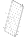
- FIG. 1 is a front perspective view of the display device of one embodiment.
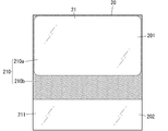
- FIG. 2 is a rear perspective view of the display device.
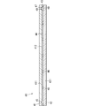
- FIG. 3 is a cross-sectional view in which a part of the display device is omitted.
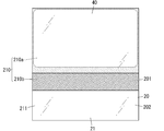
- FIG. 4 is an exploded perspective view of the display device.
- FIG. 5 is a perspective view of the glass panel unit of the display device.
- FIG. 6 is a cross-sectional view of the glass panel unit.
- FIG. 7 is an explanatory diagram of the configuration of the display device.
- FIG. 8 is an explanatory diagram of the configuration of the display device.
- FIG. 9 is an explanatory diagram of the configuration of the display device.
- FIG. 10 is an explanatory diagram of the configuration of the display device.
- FIG. 11 is an explanatory diagram of a usage example of the display device.
- FIG. 12 is an explanatory diagram of a moving body including the display device.
- FIGS. 1 and 2 show a display device 10 of one embodiment.
- the display device 10 is a so-called transmissive display device (transparent display device).
- the transmissive display device makes it possible to see through the back (background) of the transmissive display device.
- the transmissive display device can show the background and also show the image, if necessary. Further, the transmissive display device can display desired information on the background without impairing the visibility of the background.
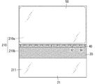
- the display device 10 of the present embodiment includes a glass plate 20, a transmissive display panel 31, and a glass panel unit 40.
- the display panel 31 faces the predetermined area 210 of the glass plate 20 and fits within the predetermined area 210.
- the glass panel unit 40 is located between the predetermined area 210 of the glass plate 20 and the display panel 31, fits within the predetermined area 210, and has an internal space 44 in a decompressed state.
- the predetermined area 210 is shown by hatching in order to show the predetermined area 210 in an easy-to-understand manner.
- the glass panel unit 40 is shown in a simplified manner.
- the display device 10 includes a glass panel unit 40 between the display panel 31 and the glass plate 20. Since the glass panel unit 40 has an internal space 44 and the internal space 44 is in a decompressed state, the amount of heat transferred between the glass plate 20 and the display panel 31 can be reduced. Therefore, in the display device 10, the display panel 31 can be protected from heat by the glass panel unit 40, and the heat insulating performance can be improved. Further, since the glass panel unit 40 is protected by the glass plate 20 and the display panel 31, the possibility of damage to the glass panel unit 40 can be reduced and the durability performance can be improved. Therefore, according to the display device 10, the durability performance can be improved while improving the heat insulating performance.
- the display device 10 is a transmissive display device. As shown in FIG. 4, the display device 10 includes a glass plate 20, a display unit 30, a glass panel unit 40, a protective plate 50, a circuit unit 60, a cushioning member 70, a frame unit 80, and a cover 90. And.
- the glass plate 20 has a rectangular flat plate shape. Further, the glass plate 20 has a property of transmitting visible light so that the background can be visually recognized through the glass plate 20. In particular, the glass plate 20 is preferably colorless and transparent.
- the material of the glass plate 20 is, for example, soda lime glass, high strain point glass, non-alkali glass, quartz glass, and neoceram.
- the glass plate 20 is so-called tempered glass. Examples of tempered glass include physically tempered glass, chemically tempered glass, and heat tempered glass. Further, the glass plate 20 has higher strength than both the display panel 31 and the glass panel unit 40. That is, the glass plate 20 has a function of protecting the display panel 31 and the glass panel unit 40.
- the glass plate 20 has a first surface 21 (see FIG. 4) and a second surface 22 (see FIG. 1), which are both sides in the thickness direction.
- the first surface 21 is a surface (inner surface) facing the inside of the display device 10
- the second surface 22 is a surface (outer surface) facing the outside of the display device 10.
- the glass plate 20 has a uniform thickness as a whole.
- the glass plate 20 is partially curved. That is, the glass plate 20 is a bent glass plate. More specifically, as shown in FIG. 4, one end (lower end of FIG. 4) of the glass plate 20 in the direction corresponding to the vertical direction of the display panel 31 (vertical direction of FIG. 4) is curved.
- the glass plate 20 includes a flat surface portion 201 and a curved surface portion 202.
- the flat surface portion 201 has a flat rectangular plate shape.
- the curved surface portion 202 has a rectangular plate shape extending from one end of the flat surface portion 201 and curved in the thickness direction.
- the first surface 21 is a flat surface in the portion corresponding to the flat surface portion 201, and is a concave surface in the portion corresponding to the curved surface portion 202.
- the second surface 22 is a flat surface in a portion corresponding to the flat surface portion 201, and is a convex surface in a portion corresponding to the curved surface portion 202.
- the first surface 21 of the glass plate 20 includes a predetermined area 210 and a mounting area 211.
- the predetermined area 210 is an area for arranging the display panel 31, the glass panel unit 40, and the protective plate 50.
- the predetermined area 210 is an area used for displaying an image by the display panel 31.
- the predetermined region 210 includes a transmission region 210a and an opaque region 210b.
- the transmission region 210a is a region through which light is transmitted.
- the transmission region 210a has a rectangular shape.
- the opaque region 210b is a region surrounding the transparent region 210a.
- the opaque region 210b is a region that does not transmit light.
- the opaque region 210b is indicated by dot hatching.
- the opaque region 210b has a rectangular frame shape.
- the opaque region 210b is a dark region.
- the dark color can be black, blue, or the like.
- the opaque region 210b is provided by forming a black layer in a predetermined region of the first surface 21 of the glass plate 20 by a printing technique.
- the mounting area 211 is an area used for mounting the display device 10 on an object.
- the predetermined area 210 is the area corresponding to the flat surface portion 201
- the mounting area 211 is the area corresponding to the curved surface portion 202.
- the display unit 30, the glass panel unit 40, and the protective plate 50 are arranged so as to overlap the glass plate 20.
- the glass panel unit 40, the display unit 30, and the protective plate 50 are arranged on the glass plate 20 so as to overlap each other in this order.
- the glass panel unit 40 is a vacuum heat insulating glass unit in this embodiment.
- the vacuum heat insulating glass unit is a kind of double glazing panel including at least a pair of glass panels, and has a vacuum space (decompression space) between the pair of glass panels.
- the glass panel unit 40 includes a pair of panels (first and second panels) 41 and 42 and a frame body 43. Further, the glass panel unit 40 has a space (internal space) 44 surrounded by a pair of panels 41 and 42 and a frame body 43. Further, the glass panel unit 40 includes a gas adsorbent 45 and a plurality of pillars (spacers) 46 in the internal space 44. In addition, in FIG. 5 and FIG. 6, the dimensions of the glass panel unit 40 are different from those in FIG. 4 in order to illustrate the glass panel unit 40 in an easy-to-understand manner.
- the first and second panels 41 and 42 are located opposite to each other. In the present embodiment, the first and second panels 41 and 42 are located so as to face each other with a slight distance from each other.
- the first panel 41 includes a first glass panel 411 and a low emissivity film 412 formed on the first glass panel 411.
- the low emissivity film 412 is a film containing a metal having low radioactivity such as silver, and has a function of suppressing heat transfer due to radiation.
- the low emissivity film 412 is formed on the surface of the first glass panel 411 facing the internal space 44. In this embodiment, the low radiation film 412 is a so-called Low-E film.
- the size of the first panel 41 is determined by the size of the first glass panel 411.
- the second panel 42 includes a second glass panel 421.
- the second panel 42 is located so as to face the first panel 41.
- the size of the second panel 42 is determined by the size of the second glass panel 421.
- the first and second panels 41 and 42 have the same shape.
- the first and second panels 41 and 42 are both rectangular flat plates.
- the first and second panels 41 and 42 have a property of transmitting visible light so that the background can be visually recognized through the glass panel unit 40.
- the first and second panels 41 and 42 are preferably colorless and transparent.
- the materials of the first and second glass panels 411 and 421 of the first and second panels 41 and 42 are, for example, soda lime glass, high strain point glass, non-alkali glass, quartz glass, and neoceram.
- the first and second glass panels 411 and 421 are so-called tempered glass. Examples of tempered glass include physically tempered glass, chemically tempered glass, and heat tempered glass.
- the frame body 43 is located between the first and second panels 41 and 42, and the first and second panels 41 and 42 are airtightly joined to each other. As a result, the internal space 44 surrounded by the first and second panels 41 and 42 and the frame body 43 is formed.
- the internal space 44 is in a decompressed state. More specifically, the internal space 44 is in a vacuum state. In other words, the internal space 44 is in a state where the internal pressure is lower than the atmospheric pressure.
- the frame body 43 is formed of a heat adhesive (sealing material). In other words, the frame 43 is a cured thermal adhesive.
- the thermal adhesive is, for example, a glass frit. An example of a glass frit is a low melting point glass frit.
- low melting point glass frit examples include bismuth-based glass frit, lead-based glass frit, and vanadium-based glass frit.
- the outer shape of the frame body 43 is the same as that of the first and second panels 41 and 42.
- the frame body 43 is formed along the outer circumferences of the first and second panels 41 and 42.
- the thermal adhesive is not limited to the glass frit, and may be, for example, a low melting point metal or a hot melt adhesive.
- the gas adsorbent 45 is arranged in the internal space 44. Specifically, the gas adsorbent 45 has a circular plate shape and is arranged on the first panel 41. The gas adsorbent 45 is in the vicinity of the outer edge of the first panel 41 (that is, the outer edge of the glass panel unit 40). In particular, in the present embodiment, the gas adsorbent 45 is provided at two of the four corners of the first panel 41.
- the gas adsorbent 45 is used to adsorb unnecessary gas (residual gas or the like).
- the unnecessary gas is, for example, a gas released from the heat adhesive when the heat adhesive forming the frame 43 is heated.
- the gas adsorbent 45 has a getter.
- Getter is a material that has the property of adsorbing molecules smaller than a predetermined size.
- the getter is, for example, an evaporative getter.
- the evaporation type getter has a property of releasing adsorbed molecules when the temperature exceeds a predetermined temperature (activation temperature). Therefore, even if the adsorption capacity of the evaporative getter decreases, the adsorption capacity of the evaporative getter can be restored by heating the evaporative getter to the activation temperature or higher.
- the evaporative getter is, for example, a zeolite or an ion-exchanged zeolite (eg, a copper ion-exchanged zeolite).
- the gas adsorbent 45 includes the powder of this getter. Specifically, the gas adsorbent 45 was obtained by dissolving a liquid containing getter powder (for example, a dispersion obtained by dispersing getter powder in a liquid or by dissolving getter powder in a liquid). It is formed by applying a solution) and solidifying it. In this case, the gas adsorbent 45 can be made smaller. Therefore, the gas adsorbent 45 can be arranged even if the internal space 44 is narrow.
- a liquid containing getter powder for example, a dispersion obtained by dispersing getter powder in a liquid or by dissolving getter powder in a liquid. It is formed by applying a solution) and solidifying it.
- the gas adsorbent 45 can be made smaller. Therefore, the gas adsorbent 45 can be arranged even if the internal space 44 is narrow.
- the plurality of pillars 46 are arranged in the internal space 44.
- the plurality of pillars 46 are used to maintain a predetermined interval between the first and second panels 41 and 42. That is, the plurality of pillars 46 are used to maintain the distance between the first and second panels 41, 42 at a desired value.
- the size of the pillars 46, the number of pillars 46, the distance between the pillars 46, and the arrangement pattern of the pillars 46 can be appropriately selected.
- Each pillar 46 is a columnar shape having a height substantially equal to the predetermined interval.
- the pillar 46 is preferably of a size that is difficult for humans to see.
- the pillar 46 has a diameter of 1 mm and a height of 100 ⁇ m.
- Each pillar 46 may have a desired shape such as a prismatic shape or a spherical shape. It is preferable that all or part of the plurality of pillars 46 is made of a resin such as polyimide.
- the glass panel unit 40 is provided with an exhaust hole 47.
- the exhaust hole 47 is formed in at least one of the first panel 41 and the second panel 42. In the present embodiment, the exhaust hole 47 is formed only in the first panel 41. Further, the exhaust hole 47 is near the outer edge of the first panel 41 (that is, the outer edge of the glass panel unit 40). In this embodiment, the exhaust hole 47 is located at the corner of the first panel 41.
- the exhaust hole 47 is used to reduce the pressure in the internal space 44. That is, the internal space 44 is decompressed by exhausting the internal space 44 from the exhaust hole 47. After the internal space 44 is decompressed, the exhaust hole 47 is sealed. A sealing material 48 and a pressing member 49 are used to seal the exhaust hole 47.
- the sealing material 48 and the pressing member 49 have a size that can be inserted into the exhaust hole 47.
- the sealing material 48 is, for example, a glass frit.
- the pressing member 49 has a plate shape.
- the pressing member 49 is arranged on the sealing material 48 on the opposite side of the second panel 42. Then, while exhausting the internal space 44 through the exhaust hole 47, the sealing material 48 is melted, and the sealing material 48 is deformed by the pressing member 49 to close the exhaust hole 47. As a result, the internal space 44 is sealed in the reduced pressure state.
- the glass panel unit 40 has a rectangular plate shape as a whole. As shown in FIG. 8, the glass panel unit 40 is arranged on the first surface 21 of the glass plate 20. More specifically, the glass panel unit 40 is arranged in a predetermined area 210 of the glass plate 20. The glass panel unit 40 has a size that fits within a predetermined area 210 of the glass plate 20. The glass panel unit 40 has the same dimensions as the glass plate 20 in the direction corresponding to the lateral direction of the display panel 31 (horizontal direction in FIG. 8). In the present embodiment, the glass panel unit 40 is larger than the transmission region 210a of the predetermined region 210, and the outer edge (including the frame 43) of the glass panel unit 40 is in the impermeable region 210b.
- both side surfaces of the glass plate 20 and the glass panel unit 40 coincide with each other in both directions (horizontal directions in FIG. 8) corresponding to the lateral direction of the display panel 31. Further, the side surfaces of the glass plate 20 and the glass panel unit 40 coincide with each other in one direction (upward direction in FIG. 8) corresponding to the vertical direction of the display panel 31.
- the gas adsorbent 45 and the exhaust hole 47 are located near the outer edge of the glass panel unit 40. In this embodiment, the gas adsorbent 45 and the exhaust hole 47 are also in the impermeable region 210b. In FIG. 8, the gas adsorbent 45 and the exhaust hole 47 are not shown.
- the display unit 30 is a functional unit for displaying the image P10 (see FIG. 11).
- the display unit 30 includes a display panel 31 and a drive unit 32.
- the display panel 31 is a transmissive display.
- An example of a transmissive display is a display using a transparent organic light emitting diode (OLED). Since the configuration related to the image display of the display panel 31 may be a conventionally known configuration, detailed description thereof will be omitted.
- the display panel 31 has a rectangular plate shape as a whole. As shown in FIGS. 3 and 9, the display panel 31 is arranged on the surface of the glass panel unit 40 opposite to the glass plate 20. More specifically, the display panel 31 is arranged in a predetermined area 210 of the glass plate 20 in a plan view. The display panel 31 has a size that fits in a predetermined area 210 of the glass plate 20.
- the display panel 31 is smaller in size than the glass plate 20 in the direction corresponding to the lateral direction of the display panel 31 (horizontal direction in FIG. 9), but is larger than the transmission area 210a in the predetermined area 210.
- the display panel 31 is larger than the transparent region 210a of the predetermined region 210, and the outer edge of the display panel 31 is located in the opaque region 210b.
- both side surfaces of the display panel 31 are inside the display device 10 with respect to both side surfaces of the glass plate 20.
- the side surface of the display panel 31 is inside the display device 10 from the side surface of the glass plate 20.
- the drive unit 32 is a device for controlling the display panel 31 and displaying an image on the display panel 31. Since the configuration of the drive unit 32 may be a conventionally known configuration, detailed description thereof will be omitted.
- the drive unit 32 is arranged so as not to overlap the display panel 31. In the present embodiment, the drive unit 32 is arranged at one end (lower end in FIG. 9) of the display panel 31 in the vertical direction (length direction, height direction) along the horizontal direction (width direction) of the display panel 31. ing. Further, as shown in FIGS. 3 and 9, the drive unit 32 is arranged on the surface of the glass panel unit 40 opposite to the glass plate 20. That is, the glass panel unit 40 is not only between the display panel 31 and the predetermined area 210 of the glass plate 20, but also between the drive unit 32 and the predetermined area 210 of the glass plate 20.
- the protective plate 50 has a rectangular flat plate shape as a whole. As shown in FIGS. 3 and 10, the protective plate 50 is arranged on the surface of the display panel 31 opposite to the glass panel unit 40. More specifically, the protective plate 50 is arranged in a predetermined area 210 of the glass plate 20 in a plan view. The protective plate 50 has a size that fits within the predetermined area 210 of the glass plate 20. The protective plate 50 has the same dimensions as the glass plate 20 in the direction corresponding to the lateral direction of the display panel 31 (horizontal direction in FIG. 10). In the present embodiment, the protective plate 50 is larger than the transmission region 210a of the predetermined region 210, and the outer edge of the protection plate 50 is in the impermeable region 210b.
- both side surfaces of the glass plate 20 and the protective plate 50 coincide with each other in both directions (horizontal directions in FIG. 10) corresponding to the lateral direction of the display panel 31. Further, the side surfaces of the glass plate 20 and the protective plate 50 coincide with each other in one direction (upward direction in FIG. 10) corresponding to the vertical direction of the display panel 31.
- the protective plate 50 is set in a direction corresponding to the vertical direction of the display panel 31 so as to expose the drive unit 32. Further, the protective plate 50 has a uniform thickness as a whole. Both sides of the protective plate 50 in the thickness direction are flat. Further, the protective plate 50 has a property of transmitting visible light so that the image projected by the display panel 31 can be visually recognized through the protective plate 50.
- the protective plate 50 is preferably colorless and transparent.
- the material of the protective plate 50 is, for example, soda lime glass, high-strain point glass, non-alkali glass, quartz glass, and neoceram.
- the protective plate 50 is so-called tempered glass. Examples of tempered glass include physically tempered glass, chemically tempered glass, and heat tempered glass.
- the protective plate 50 has higher strength than both the display panel 31 and the glass panel unit 40. That is, the protective plate 50 has a function of protecting the display panel 31 and the glass panel unit 40.
- the circuit unit 60 is a functional unit for controlling the display unit 30.
- the circuit unit 60 controls the display unit 30 based on an image signal (video signal) given from an external device, and causes the display panel 31 to display an image.
- the circuit unit 60 is arranged in a predetermined area 210 on the first surface 21 of the glass plate 20. In particular, the circuit unit 60 is arranged in the vicinity of the mounting region 211 in the opaque region 210b of the predetermined region 210.
- the cushioning member 70 is arranged between the glass panel unit 40 and the circuit unit 60.
- the cushioning member 70 prevents a collision between the glass panel unit 40 and the circuit unit 60, and protects the glass panel unit 40 and the circuit unit 60.
- the cushioning member 70 has an elongated square rod shape.
- the cushioning member 70 can be formed of a material known as a cushioning material such as urethane foam.
- the frame portion 80 is configured to collectively cover at least a part of the outer edge of the glass plate 20, the display panel 31, the glass panel unit 40, and the protective plate 50.
- the glass plate 20, the display panel 31, the glass panel unit 40, and the protective plate 50 have a rectangular plate shape.
- the frame portion 80 is configured to cover three of the four sides constituting the outer edges of the glass plate 20, the display panel 31, the glass panel unit 40, and the protective plate 50. ..
- the frame portion 80 covers three sides corresponding to a predetermined area 210 of the glass plate 20 among the four sides constituting the outer edges of the glass plate 20, the display panel 31, the glass panel unit 40, and the protective plate 50. As shown in FIG.
- the frame portion 80 includes a first side portion 81 and a pair of second side portions 82.
- the first side portion 81 and the pair of second side portions 82 are both long rod-shaped, and have a U-shaped cross section orthogonal to the length direction. That is, a part of the outer edge of the glass plate 20, the display panel 31, the glass panel unit 40, and the protective plate 50 is inserted inside the first side portion 81 and the pair of the second side portions 82 cities (see FIG. 3). ).
- the frame portion 80 can be formed of a resin material.
- the frame portion 80 may be formed of a metal material.
- the cover 90 is a member for protecting the drive unit 32 and the circuit unit 60.
- the cover 90 has a rectangular box shape with one side open.
- the cover 90 is arranged on the first surface 21 of the glass plate 20.
- the cover 90 is arranged on the first surface 21 of the glass plate 20 so as to cover the drive unit 32 and the circuit unit 60.
- the cover 90 can be made of a resin material.
- the cover 90 may be made of a metal material.
- the display device 10 of the present embodiment can display the image P10 by the display panel 31. Further, since the display device 10 is a transparent display device, it is possible to see through the back (background) of the display device 10. That is, the display device 10 can show the background and can also show the image P10 or the like as needed. Further, the display device 10 can display desired information on the background by the image P10 without impairing the visibility of the background. As an example, the display device 10 can be applied to a mobile body 100 as shown in FIG. In this case, the object to which the display device 10 is attached may be the moving body main body 110 of the moving body 100.
- the moving body 100 is a vehicle, and in the present embodiment, it is an automobile.
- the moving body main body 110 is a vehicle body.
- the display device 10 is mounted on the mobile body 110 as a window (windshield) of the mobile body 100.
- the display device 10 superimposes various driving support information such as vehicle speed information, navigation information, pedestrian information, forward vehicle information, lane departure information, and vehicle condition information on the background by the display panel 31. Can be displayed and made visible to the user.
- the display device 10 is not limited to automobiles, but can be applied to mobile objects other than automobiles, such as motorcycles, trains, aircraft, construction machinery, and ships. Further, the display device 10 can be applied not only to a moving body but also to a fixed body. Examples of fixed bodies include vending machines, showcases, and facilities. The display device 10 can also be used as a window in vending machines, showcases, and facilities. Examples of facilities include residential buildings (for example, detached houses, apartment houses) and non-residential facilities (for example, factories, commercial facilities, amusement facilities, hospitals, offices, buildings).
- the display device 10 has a rectangular shape, but the display device 10 may have a desired shape such as a circular shape or a polygonal shape. That is, the glass plate 20, the display panel 31, the glass panel unit 40, and the protective plate 50 may have a desired shape such as a circular shape or a polygonal shape instead of a rectangular shape. Further, the shape and size of the display device 10 are determined according to the use of the display device 10. As an example, the display device 10 may have a shape corresponding to the window (windshield, side window, rear window, etc.) of the moving body 100.
- the display device 10 does not have to include the protective plate 50. Further, the display device 10 does not have to include the circuit unit 60. Further, the display device 10 does not have to include the cushioning member 70. Further, the display device 10 does not have to include the frame portion 80. Further, the display device 10 does not have to include the cover 90.
- the glass plate 20 may be provided with a functional layer having desired physical characteristics on at least one of the first surface 21 and the second surface 22.
- the functional layer is, for example, a film that reflects light of a specific wavelength (infrared reflective film, ultraviolet reflective film), a glass film for improving the intensity, an antireflection film, and the like.
- the functional layer may be formed by coating or may be provided by attaching a film. This point also applies to the display panel 31, the glass panel unit 40, and the protective plate 50.
- the glass plate 20 may be a bent glass plate including decoration, a laminated bent glass plate, or a double-layer bent glass plate.
- the glass plate 20 is not limited to the bent glass plate, and may be linear glass. That is, the glass plate 20 may be composed of only the flat surface portion 201 without the curved surface portion 202.
- the display panel 31 of the display unit 30 is a display using a transparent LED (transparent OLED display), but may be a transparent liquid crystal or a transparent LED display. That is, a conventionally well-known transmissive display or transparent display can be adopted as the display panel 31.
- the display panel 31 may be joined to the glass panel unit 40 via an interlayer film.
- the interlayer film By using the interlayer film, the effect of preventing the glass from scattering when the display panel 31 and the glass panel unit 40 are damaged can be expected.
- the material of the interlayer film include EVA, PVB, ionomer resin, and polyolefin-based adhesive polymer.
- the interlayer film may have a property of transmitting visible light so that the background can be visually recognized through the interlayer film.
- the interlayer film is preferably colorless and transparent.
- the bonding between the display panel 31 and the glass panel unit 40 may be realized by direct bonding of resin filling. That is, the display panel 31 and the glass panel unit 40 may be joined without a gap by using an adhesive.
- the adhesive include a transparent pressure-sensitive adhesive (OCA) and an ultraviolet curable resin.
- the configuration of the glass panel unit 40 is not limited to the above configuration, and may be the same as the configuration of a conventionally known vacuum heat insulating glass unit.
- the glass panel unit 40 may have a configuration without an exhaust hole 47. Since the glass panel unit without an exhaust port is already well known, it will not be described in particular.
- the glass panel unit 40 may be joined to the glass plate 20 via an interlayer film as described above.
- the bonding between the glass panel unit 40 and the glass plate 20 may be realized by direct bonding of resin filling. That is, the glass panel unit 40 and the glass plate 20 may be joined without gaps by using the adhesive as described above.
- the protective plate 50 may be joined to the display panel 31 via an interlayer film as described above.
- the bonding between the protective plate 50 and the display panel 31 may be realized by direct bonding of resin filling. That is, the protective plate 50 and the display panel 31 may be joined without a gap by using the adhesive as described above.
- the first aspect is a display device (10), which includes a glass plate (20), a transmissive display panel (31), and a glass panel unit (40).
- the display panel (31) faces a predetermined area (210) of the glass plate (20) and fits within the predetermined area (210).
- the glass panel unit (40) is located between a predetermined region (210) of the glass plate (20) and the display panel (31), fits within the predetermined region (210), and is an internal space (44) in a decompressed state. ). According to this aspect, the durability performance can be improved while improving the heat insulating performance.
- the second aspect is the display device (10) based on the first aspect.
- the glass plate (20) has a mounting area (211) for mounting on the object (110).
- the mounting region (211) is in a region of the glass plate (20) that does not overlap with the predetermined region (210). According to this aspect, the object (110) of the display device (10) can be easily attached.
- the third aspect is the display device (10) based on the first or second aspect.
- the glass plate (20) includes a flat surface portion (201) and a curved surface portion (202).
- the predetermined region (210) is on the flat surface portion (201).
- the display panel (31) can be easily arranged.
- the fourth aspect is the display device (10) based on any one of the first to third aspects.
- the display device (10) further includes a drive unit (32) that drives the display panel (31).
- the drive unit (32) is arranged so as not to overlap the display panel (31).
- the drive unit (32) can be arranged in a place that does not affect the visibility of the image (P10) by the display panel (31).
- the fifth aspect is the display device (10) based on the fourth aspect.
- the drive unit (32) is arranged on a surface of the glass panel unit (40) opposite to the glass plate (20).
- the glass panel unit (40) can also be used to protect the drive unit (32) from heat.
- the sixth aspect is the display device (10) based on any one of the first to fifth aspects.
- the predetermined region (210) includes a transmission region (210a) and an impermeable region (210b) surrounding the transmission region (210a).
- the outer edge of the glass panel unit (40) is in the impermeable region (210b). According to this aspect, the outer edge of the glass panel unit (40) can be hidden by the opaque region (210b).
- the seventh aspect is the display device (10) based on the sixth aspect.
- the opaque region (210b) is a dark region. According to this aspect, the outer edge of the glass panel unit (40) can be hidden by the opaque region (210b).
- the eighth aspect is the display device (10) based on the sixth or seventh aspect.
- the glass panel unit (40) has an exhaust hole (47) sealed by a sealing material (48).
- the exhaust hole (47) is in the impermeable region (210b). According to this aspect, it is possible to make the exhaust hole (47) difficult to see.
- the ninth aspect is a display device (10) based on any one of the first to eighth aspects.
- the glass plate (20) has higher strength than both the display panel (31) and the glass panel unit (40). According to this aspect, the display panel (31) and the glass panel unit (40) can be protected by the glass plate (20).
- the tenth aspect is the moving body (100), and the display device (10) according to any one of the first to ninth aspects and the moving body main body (10) on which the display device (10) is mounted as a window. 110) and. According to this aspect, the durability performance can be improved while improving the heat insulating performance.
- Display device 20 Glass plate 201 Flat surface part 202 Curved surface part 210 Predetermined area 210a Transparent area 210b Non-transparent area 211 Mounting area 31 Display panel 32 Drive unit 40 Glass panel unit 44 Internal space 47 Exhaust hole 48 Encapsulant P10 Image 100 Moving object 110 Moving body body
Landscapes
- Engineering & Computer Science (AREA)
- Chemical & Material Sciences (AREA)
- Mechanical Engineering (AREA)
- Combustion & Propulsion (AREA)
- Transportation (AREA)
- Physics & Mathematics (AREA)
- General Physics & Mathematics (AREA)
- Nonlinear Science (AREA)
- Theoretical Computer Science (AREA)
- Mathematical Physics (AREA)
- Crystallography & Structural Chemistry (AREA)
- Optics & Photonics (AREA)
- Devices For Indicating Variable Information By Combining Individual Elements (AREA)
Abstract
L'objet de la présente invention est de fournir un dispositif d'affichage qui a une durabilité améliorée tout en ayant des performances d'isolation thermique améliorées, et de fournir un corps mobile. Ce dispositif d'affichage (10) est pourvu d'une plaque de verre (20), d'un panneau d'affichage transparent (31) et d'une unité de panneau de verre (40). Le panneau d'affichage (31) fait face à une région (210) prescrite de la plaque de verre (20), et est logé dans une région (211) prescrite. L'unité de panneau de verre (40) est disposée entre le panneau d'affichage (31) et la région (210) prescrite de la plaque de verre (20), et est logée dans la région (210) prescrite. La plaque de panneau de verre (40) a un espace interne à l'état décomprimé (44).
Priority Applications (2)
| Application Number | Priority Date | Filing Date | Title |
|---|---|---|---|
| US17/767,334 US20220371440A1 (en) | 2019-10-18 | 2020-08-05 | Display device, movable object |
| JP2021552112A JP7285506B2 (ja) | 2019-10-18 | 2020-08-05 | ディスプレイ装置、移動体 |
Applications Claiming Priority (2)
| Application Number | Priority Date | Filing Date | Title |
|---|---|---|---|
| JP2019191498 | 2019-10-18 | ||
| JP2019-191498 | 2019-10-18 |
Publications (1)
| Publication Number | Publication Date |
|---|---|
| WO2021075127A1 true WO2021075127A1 (fr) | 2021-04-22 |
Family
ID=75537591
Family Applications (1)
| Application Number | Title | Priority Date | Filing Date |
|---|---|---|---|
| PCT/JP2020/029963 WO2021075127A1 (fr) | 2019-10-18 | 2020-08-05 | Dispositif d'affichage, corps mobile |
Country Status (3)
| Country | Link |
|---|---|
| US (1) | US20220371440A1 (fr) |
| JP (1) | JP7285506B2 (fr) |
| WO (1) | WO2021075127A1 (fr) |
Families Citing this family (1)
| Publication number | Priority date | Publication date | Assignee | Title |
|---|---|---|---|---|
| KR102584220B1 (ko) * | 2023-06-08 | 2023-10-05 | 주식회사 지엘아이엔에스 | 방수 및 진동방지 성능이 강화된 클러스터 |
Citations (8)
| Publication number | Priority date | Publication date | Assignee | Title |
|---|---|---|---|---|
| JPH11198679A (ja) * | 1998-01-14 | 1999-07-27 | Harness Syst Tech Res Ltd | 表示装置 |
| JP2003258211A (ja) * | 2001-12-28 | 2003-09-12 | Semiconductor Energy Lab Co Ltd | 半導体装置の作製方法 |
| JP2004529392A (ja) * | 2001-06-12 | 2004-09-24 | ヴライト イノヴェーションズ リミテッド | 窓、窓にキャラクターを表示する方法、及び画像表示パネル |
| JP2006162890A (ja) * | 2004-12-06 | 2006-06-22 | Matsushita Electric Ind Co Ltd | 表示装置 |
| US20140078407A1 (en) * | 2012-03-06 | 2014-03-20 | Planar Systems, Inc. | Transparent electronic image display apparatus for refrigerated merchandisers and the like |
| WO2014050138A1 (fr) * | 2012-09-28 | 2014-04-03 | パナソニック株式会社 | Dispositif d'affichage |
| JP2018052758A (ja) * | 2016-09-27 | 2018-04-05 | パナソニックIpマネジメント株式会社 | ガラスパネルユニットおよびガラス窓 |
| JP2019117215A (ja) * | 2017-12-26 | 2019-07-18 | トヨタ自動車株式会社 | 自動車 |
-
2020
- 2020-08-05 US US17/767,334 patent/US20220371440A1/en active Pending
- 2020-08-05 WO PCT/JP2020/029963 patent/WO2021075127A1/fr active Application Filing
- 2020-08-05 JP JP2021552112A patent/JP7285506B2/ja active Active
Patent Citations (8)
| Publication number | Priority date | Publication date | Assignee | Title |
|---|---|---|---|---|
| JPH11198679A (ja) * | 1998-01-14 | 1999-07-27 | Harness Syst Tech Res Ltd | 表示装置 |
| JP2004529392A (ja) * | 2001-06-12 | 2004-09-24 | ヴライト イノヴェーションズ リミテッド | 窓、窓にキャラクターを表示する方法、及び画像表示パネル |
| JP2003258211A (ja) * | 2001-12-28 | 2003-09-12 | Semiconductor Energy Lab Co Ltd | 半導体装置の作製方法 |
| JP2006162890A (ja) * | 2004-12-06 | 2006-06-22 | Matsushita Electric Ind Co Ltd | 表示装置 |
| US20140078407A1 (en) * | 2012-03-06 | 2014-03-20 | Planar Systems, Inc. | Transparent electronic image display apparatus for refrigerated merchandisers and the like |
| WO2014050138A1 (fr) * | 2012-09-28 | 2014-04-03 | パナソニック株式会社 | Dispositif d'affichage |
| JP2018052758A (ja) * | 2016-09-27 | 2018-04-05 | パナソニックIpマネジメント株式会社 | ガラスパネルユニットおよびガラス窓 |
| JP2019117215A (ja) * | 2017-12-26 | 2019-07-18 | トヨタ自動車株式会社 | 自動車 |
Also Published As
| Publication number | Publication date |
|---|---|
| JP7285506B2 (ja) | 2023-06-02 |
| US20220371440A1 (en) | 2022-11-24 |
| JPWO2021075127A1 (fr) | 2021-04-22 |
Similar Documents
| Publication | Publication Date | Title |
|---|---|---|
| TWI588791B (zh) | 顯示裝置 | |
| CN107464824B (zh) | 一种显示面板 | |
| US8187682B2 (en) | Protective glass against ionizing radiation | |
| JP5340594B2 (ja) | 強い環境光のための、カバーガラスとエアギャップとディスプレイとを有するスタックの光学補償 | |
| KR101841672B1 (ko) | 투명 디스플레이를 구비한 냉장고 도어용 이중유리 | |
| TWI617732B (zh) | 玻璃平板單元及玻璃窗 | |
| CN107690388A (zh) | 包含导光板的汽车玻璃窗和层叠结构 | |
| JP6775190B2 (ja) | ガラスパネルユニットおよびガラス窓 | |
| JP7380673B2 (ja) | 合わせガラス | |
| WO2021075127A1 (fr) | Dispositif d'affichage, corps mobile | |
| JP6994675B2 (ja) | ガラスパネルユニットの製造方法、およびガラス窓の製造方法 | |
| WO2016017530A1 (fr) | Dispositif d'affichage | |
| JPWO2019012962A1 (ja) | 自動車用窓ガラス | |
| JP2007233160A (ja) | 大型表示装置及びこれに用いる表示デバイス、表示モジュール | |
| JP6565581B2 (ja) | 映像表示透明部材を備える透明スクリーン、および映像表示システム | |
| WO2016121591A1 (fr) | Plaque en verre architectural comportant un dispositif d'affichage et structure en verre architectural | |
| CN211718672U (zh) | 一种中空双稳态液晶调光器件 | |
| US10604992B2 (en) | Glass panel unit | |
| WO2014175193A1 (fr) | Verre multicouche avec affichage, porte en verre pour boîtier de présentation et boîtier de présentation | |
| JP6688785B2 (ja) | 複層ガラス | |
| CN108490665A (zh) | 内嵌式液晶显示屏 | |
| WO2016174922A1 (fr) | Verre feuilleté | |
| JP7199017B2 (ja) | ガラスパネルユニットの製造方法 | |
| KR20140044111A (ko) | 평판 표시 장치 | |
| JP6287013B2 (ja) | 表示装置及びコネクタ |
Legal Events
| Date | Code | Title | Description |
|---|---|---|---|
| 121 | Ep: the epo has been informed by wipo that ep was designated in this application |
Ref document number: 20876219 Country of ref document: EP Kind code of ref document: A1 |
|
| ENP | Entry into the national phase |
Ref document number: 2021552112 Country of ref document: JP Kind code of ref document: A |
|
| NENP | Non-entry into the national phase |
Ref country code: DE |
|
| 122 | Ep: pct application non-entry in european phase |
Ref document number: 20876219 Country of ref document: EP Kind code of ref document: A1 |