WO2021070828A1 - Dispositif d'entraînement hydraulique - Google Patents
Dispositif d'entraînement hydraulique Download PDFInfo
- Publication number
- WO2021070828A1 WO2021070828A1 PCT/JP2020/037901 JP2020037901W WO2021070828A1 WO 2021070828 A1 WO2021070828 A1 WO 2021070828A1 JP 2020037901 W JP2020037901 W JP 2020037901W WO 2021070828 A1 WO2021070828 A1 WO 2021070828A1
- Authority
- WO
- WIPO (PCT)
- Prior art keywords
- pressure
- air
- liquid
- hydraulic
- chamber
- Prior art date
Links
- 239000007788 liquid Substances 0.000 claims abstract description 215
- ZZUFCTLCJUWOSV-UHFFFAOYSA-N furosemide Chemical compound C1=C(Cl)C(S(=O)(=O)N)=CC(C(O)=O)=C1NCC1=CC=CO1 ZZUFCTLCJUWOSV-UHFFFAOYSA-N 0.000 claims description 15
- 230000004048 modification Effects 0.000 description 22
- 238000012986 modification Methods 0.000 description 22
- 239000012530 fluid Substances 0.000 description 13
- 238000001514 detection method Methods 0.000 description 9
- XLYOFNOQVPJJNP-UHFFFAOYSA-N water Substances O XLYOFNOQVPJJNP-UHFFFAOYSA-N 0.000 description 6
- 238000010586 diagram Methods 0.000 description 5
- 238000006243 chemical reaction Methods 0.000 description 3
- 238000005461 lubrication Methods 0.000 description 2
- 238000011144 upstream manufacturing Methods 0.000 description 2
- 206010010904 Convulsion Diseases 0.000 description 1
- 230000001133 acceleration Effects 0.000 description 1
- 239000003638 chemical reducing agent Substances 0.000 description 1
- 238000011109 contamination Methods 0.000 description 1
- 230000006866 deterioration Effects 0.000 description 1
- 230000000694 effects Effects 0.000 description 1
- 239000000463 material Substances 0.000 description 1
- 229910052751 metal Inorganic materials 0.000 description 1
- 239000002184 metal Substances 0.000 description 1
- 150000002739 metals Chemical class 0.000 description 1
- 229910001220 stainless steel Inorganic materials 0.000 description 1
- 239000010935 stainless steel Substances 0.000 description 1
- 239000008399 tap water Substances 0.000 description 1
- 235000020679 tap water Nutrition 0.000 description 1
Images


Classifications
-
- F—MECHANICAL ENGINEERING; LIGHTING; HEATING; WEAPONS; BLASTING
- F15—FLUID-PRESSURE ACTUATORS; HYDRAULICS OR PNEUMATICS IN GENERAL
- F15B—SYSTEMS ACTING BY MEANS OF FLUIDS IN GENERAL; FLUID-PRESSURE ACTUATORS, e.g. SERVOMOTORS; DETAILS OF FLUID-PRESSURE SYSTEMS, NOT OTHERWISE PROVIDED FOR
- F15B11/00—Servomotor systems without provision for follow-up action; Circuits therefor
- F15B11/06—Servomotor systems without provision for follow-up action; Circuits therefor involving features specific to the use of a compressible medium, e.g. air, steam
- F15B11/072—Combined pneumatic-hydraulic systems
- F15B11/0725—Combined pneumatic-hydraulic systems with the driving energy being derived from a pneumatic system, a subsequent hydraulic system displacing or controlling the output element
-
- F—MECHANICAL ENGINEERING; LIGHTING; HEATING; WEAPONS; BLASTING
- F15—FLUID-PRESSURE ACTUATORS; HYDRAULICS OR PNEUMATICS IN GENERAL
- F15B—SYSTEMS ACTING BY MEANS OF FLUIDS IN GENERAL; FLUID-PRESSURE ACTUATORS, e.g. SERVOMOTORS; DETAILS OF FLUID-PRESSURE SYSTEMS, NOT OTHERWISE PROVIDED FOR
- F15B11/00—Servomotor systems without provision for follow-up action; Circuits therefor
- F15B11/02—Systems essentially incorporating special features for controlling the speed or actuating force of an output member
- F15B11/028—Systems essentially incorporating special features for controlling the speed or actuating force of an output member for controlling the actuating force
- F15B11/036—Systems essentially incorporating special features for controlling the speed or actuating force of an output member for controlling the actuating force by means of servomotors having a plurality of working chambers
- F15B11/0365—Tandem constructions
-
- F—MECHANICAL ENGINEERING; LIGHTING; HEATING; WEAPONS; BLASTING
- F15—FLUID-PRESSURE ACTUATORS; HYDRAULICS OR PNEUMATICS IN GENERAL
- F15B—SYSTEMS ACTING BY MEANS OF FLUIDS IN GENERAL; FLUID-PRESSURE ACTUATORS, e.g. SERVOMOTORS; DETAILS OF FLUID-PRESSURE SYSTEMS, NOT OTHERWISE PROVIDED FOR
- F15B11/00—Servomotor systems without provision for follow-up action; Circuits therefor
- F15B11/06—Servomotor systems without provision for follow-up action; Circuits therefor involving features specific to the use of a compressible medium, e.g. air, steam
- F15B11/072—Combined pneumatic-hydraulic systems
-
- F—MECHANICAL ENGINEERING; LIGHTING; HEATING; WEAPONS; BLASTING
- F15—FLUID-PRESSURE ACTUATORS; HYDRAULICS OR PNEUMATICS IN GENERAL
- F15B—SYSTEMS ACTING BY MEANS OF FLUIDS IN GENERAL; FLUID-PRESSURE ACTUATORS, e.g. SERVOMOTORS; DETAILS OF FLUID-PRESSURE SYSTEMS, NOT OTHERWISE PROVIDED FOR
- F15B11/00—Servomotor systems without provision for follow-up action; Circuits therefor
- F15B11/02—Systems essentially incorporating special features for controlling the speed or actuating force of an output member
- F15B11/028—Systems essentially incorporating special features for controlling the speed or actuating force of an output member for controlling the actuating force
- F15B11/032—Systems essentially incorporating special features for controlling the speed or actuating force of an output member for controlling the actuating force by means of fluid-pressure converters
- F15B11/0325—Systems essentially incorporating special features for controlling the speed or actuating force of an output member for controlling the actuating force by means of fluid-pressure converters the fluid-pressure converter increasing the working force after an approach stroke
-
- F—MECHANICAL ENGINEERING; LIGHTING; HEATING; WEAPONS; BLASTING
- F15—FLUID-PRESSURE ACTUATORS; HYDRAULICS OR PNEUMATICS IN GENERAL
- F15B—SYSTEMS ACTING BY MEANS OF FLUIDS IN GENERAL; FLUID-PRESSURE ACTUATORS, e.g. SERVOMOTORS; DETAILS OF FLUID-PRESSURE SYSTEMS, NOT OTHERWISE PROVIDED FOR
- F15B15/00—Fluid-actuated devices for displacing a member from one position to another; Gearing associated therewith
- F15B15/08—Characterised by the construction of the motor unit
- F15B15/14—Characterised by the construction of the motor unit of the straight-cylinder type
- F15B15/1423—Component parts; Constructional details
- F15B15/1447—Pistons; Piston to piston rod assemblies
-
- F—MECHANICAL ENGINEERING; LIGHTING; HEATING; WEAPONS; BLASTING
- F15—FLUID-PRESSURE ACTUATORS; HYDRAULICS OR PNEUMATICS IN GENERAL
- F15B—SYSTEMS ACTING BY MEANS OF FLUIDS IN GENERAL; FLUID-PRESSURE ACTUATORS, e.g. SERVOMOTORS; DETAILS OF FLUID-PRESSURE SYSTEMS, NOT OTHERWISE PROVIDED FOR
- F15B15/00—Fluid-actuated devices for displacing a member from one position to another; Gearing associated therewith
- F15B15/08—Characterised by the construction of the motor unit
- F15B15/14—Characterised by the construction of the motor unit of the straight-cylinder type
- F15B15/149—Fluid interconnections, e.g. fluid connectors, passages
-
- F—MECHANICAL ENGINEERING; LIGHTING; HEATING; WEAPONS; BLASTING
- F15—FLUID-PRESSURE ACTUATORS; HYDRAULICS OR PNEUMATICS IN GENERAL
- F15B—SYSTEMS ACTING BY MEANS OF FLUIDS IN GENERAL; FLUID-PRESSURE ACTUATORS, e.g. SERVOMOTORS; DETAILS OF FLUID-PRESSURE SYSTEMS, NOT OTHERWISE PROVIDED FOR
- F15B3/00—Intensifiers or fluid-pressure converters, e.g. pressure exchangers; Conveying pressure from one fluid system to another, without contact between the fluids
-
- F—MECHANICAL ENGINEERING; LIGHTING; HEATING; WEAPONS; BLASTING
- F15—FLUID-PRESSURE ACTUATORS; HYDRAULICS OR PNEUMATICS IN GENERAL
- F15B—SYSTEMS ACTING BY MEANS OF FLUIDS IN GENERAL; FLUID-PRESSURE ACTUATORS, e.g. SERVOMOTORS; DETAILS OF FLUID-PRESSURE SYSTEMS, NOT OTHERWISE PROVIDED FOR
- F15B7/00—Systems in which the movement produced is definitely related to the output of a volumetric pump; Telemotors
- F15B7/001—With multiple inputs, e.g. for dual control
-
- F—MECHANICAL ENGINEERING; LIGHTING; HEATING; WEAPONS; BLASTING
- F15—FLUID-PRESSURE ACTUATORS; HYDRAULICS OR PNEUMATICS IN GENERAL
- F15B—SYSTEMS ACTING BY MEANS OF FLUIDS IN GENERAL; FLUID-PRESSURE ACTUATORS, e.g. SERVOMOTORS; DETAILS OF FLUID-PRESSURE SYSTEMS, NOT OTHERWISE PROVIDED FOR
- F15B7/00—Systems in which the movement produced is definitely related to the output of a volumetric pump; Telemotors
- F15B7/005—With rotary or crank input
- F15B7/006—Rotary pump input
-
- F—MECHANICAL ENGINEERING; LIGHTING; HEATING; WEAPONS; BLASTING
- F15—FLUID-PRESSURE ACTUATORS; HYDRAULICS OR PNEUMATICS IN GENERAL
- F15B—SYSTEMS ACTING BY MEANS OF FLUIDS IN GENERAL; FLUID-PRESSURE ACTUATORS, e.g. SERVOMOTORS; DETAILS OF FLUID-PRESSURE SYSTEMS, NOT OTHERWISE PROVIDED FOR
- F15B7/00—Systems in which the movement produced is definitely related to the output of a volumetric pump; Telemotors
- F15B7/06—Details
- F15B7/08—Input units; Master units
-
- F—MECHANICAL ENGINEERING; LIGHTING; HEATING; WEAPONS; BLASTING
- F15—FLUID-PRESSURE ACTUATORS; HYDRAULICS OR PNEUMATICS IN GENERAL
- F15B—SYSTEMS ACTING BY MEANS OF FLUIDS IN GENERAL; FLUID-PRESSURE ACTUATORS, e.g. SERVOMOTORS; DETAILS OF FLUID-PRESSURE SYSTEMS, NOT OTHERWISE PROVIDED FOR
- F15B2211/00—Circuits for servomotor systems
- F15B2211/20—Fluid pressure source, e.g. accumulator or variable axial piston pump
- F15B2211/205—Systems with pumps
- F15B2211/20507—Type of prime mover
- F15B2211/20515—Electric motor
-
- F—MECHANICAL ENGINEERING; LIGHTING; HEATING; WEAPONS; BLASTING
- F15—FLUID-PRESSURE ACTUATORS; HYDRAULICS OR PNEUMATICS IN GENERAL
- F15B—SYSTEMS ACTING BY MEANS OF FLUIDS IN GENERAL; FLUID-PRESSURE ACTUATORS, e.g. SERVOMOTORS; DETAILS OF FLUID-PRESSURE SYSTEMS, NOT OTHERWISE PROVIDED FOR
- F15B2211/00—Circuits for servomotor systems
- F15B2211/20—Fluid pressure source, e.g. accumulator or variable axial piston pump
- F15B2211/205—Systems with pumps
- F15B2211/2053—Type of pump
- F15B2211/20538—Type of pump constant capacity
-
- F—MECHANICAL ENGINEERING; LIGHTING; HEATING; WEAPONS; BLASTING
- F15—FLUID-PRESSURE ACTUATORS; HYDRAULICS OR PNEUMATICS IN GENERAL
- F15B—SYSTEMS ACTING BY MEANS OF FLUIDS IN GENERAL; FLUID-PRESSURE ACTUATORS, e.g. SERVOMOTORS; DETAILS OF FLUID-PRESSURE SYSTEMS, NOT OTHERWISE PROVIDED FOR
- F15B2211/00—Circuits for servomotor systems
- F15B2211/20—Fluid pressure source, e.g. accumulator or variable axial piston pump
- F15B2211/205—Systems with pumps
- F15B2211/2053—Type of pump
- F15B2211/20561—Type of pump reversible
-
- F—MECHANICAL ENGINEERING; LIGHTING; HEATING; WEAPONS; BLASTING
- F15—FLUID-PRESSURE ACTUATORS; HYDRAULICS OR PNEUMATICS IN GENERAL
- F15B—SYSTEMS ACTING BY MEANS OF FLUIDS IN GENERAL; FLUID-PRESSURE ACTUATORS, e.g. SERVOMOTORS; DETAILS OF FLUID-PRESSURE SYSTEMS, NOT OTHERWISE PROVIDED FOR
- F15B2211/00—Circuits for servomotor systems
- F15B2211/20—Fluid pressure source, e.g. accumulator or variable axial piston pump
- F15B2211/205—Systems with pumps
- F15B2211/2053—Type of pump
- F15B2211/20569—Type of pump capable of working as pump and motor
-
- F—MECHANICAL ENGINEERING; LIGHTING; HEATING; WEAPONS; BLASTING
- F15—FLUID-PRESSURE ACTUATORS; HYDRAULICS OR PNEUMATICS IN GENERAL
- F15B—SYSTEMS ACTING BY MEANS OF FLUIDS IN GENERAL; FLUID-PRESSURE ACTUATORS, e.g. SERVOMOTORS; DETAILS OF FLUID-PRESSURE SYSTEMS, NOT OTHERWISE PROVIDED FOR
- F15B2211/00—Circuits for servomotor systems
- F15B2211/20—Fluid pressure source, e.g. accumulator or variable axial piston pump
- F15B2211/27—Directional control by means of the pressure source
-
- F—MECHANICAL ENGINEERING; LIGHTING; HEATING; WEAPONS; BLASTING
- F15—FLUID-PRESSURE ACTUATORS; HYDRAULICS OR PNEUMATICS IN GENERAL
- F15B—SYSTEMS ACTING BY MEANS OF FLUIDS IN GENERAL; FLUID-PRESSURE ACTUATORS, e.g. SERVOMOTORS; DETAILS OF FLUID-PRESSURE SYSTEMS, NOT OTHERWISE PROVIDED FOR
- F15B2211/00—Circuits for servomotor systems
- F15B2211/60—Circuit components or control therefor
- F15B2211/63—Electronic controllers
- F15B2211/6303—Electronic controllers using input signals
- F15B2211/6306—Electronic controllers using input signals representing a pressure
- F15B2211/6313—Electronic controllers using input signals representing a pressure the pressure being a load pressure
-
- F—MECHANICAL ENGINEERING; LIGHTING; HEATING; WEAPONS; BLASTING
- F15—FLUID-PRESSURE ACTUATORS; HYDRAULICS OR PNEUMATICS IN GENERAL
- F15B—SYSTEMS ACTING BY MEANS OF FLUIDS IN GENERAL; FLUID-PRESSURE ACTUATORS, e.g. SERVOMOTORS; DETAILS OF FLUID-PRESSURE SYSTEMS, NOT OTHERWISE PROVIDED FOR
- F15B2211/00—Circuits for servomotor systems
- F15B2211/60—Circuit components or control therefor
- F15B2211/63—Electronic controllers
- F15B2211/6303—Electronic controllers using input signals
- F15B2211/6336—Electronic controllers using input signals representing a state of the output member, e.g. position, speed or acceleration
-
- F—MECHANICAL ENGINEERING; LIGHTING; HEATING; WEAPONS; BLASTING
- F15—FLUID-PRESSURE ACTUATORS; HYDRAULICS OR PNEUMATICS IN GENERAL
- F15B—SYSTEMS ACTING BY MEANS OF FLUIDS IN GENERAL; FLUID-PRESSURE ACTUATORS, e.g. SERVOMOTORS; DETAILS OF FLUID-PRESSURE SYSTEMS, NOT OTHERWISE PROVIDED FOR
- F15B2211/00—Circuits for servomotor systems
- F15B2211/60—Circuit components or control therefor
- F15B2211/665—Methods of control using electronic components
- F15B2211/6651—Control of the prime mover, e.g. control of the output torque or rotational speed
-
- F—MECHANICAL ENGINEERING; LIGHTING; HEATING; WEAPONS; BLASTING
- F15—FLUID-PRESSURE ACTUATORS; HYDRAULICS OR PNEUMATICS IN GENERAL
- F15B—SYSTEMS ACTING BY MEANS OF FLUIDS IN GENERAL; FLUID-PRESSURE ACTUATORS, e.g. SERVOMOTORS; DETAILS OF FLUID-PRESSURE SYSTEMS, NOT OTHERWISE PROVIDED FOR
- F15B2211/00—Circuits for servomotor systems
- F15B2211/60—Circuit components or control therefor
- F15B2211/665—Methods of control using electronic components
- F15B2211/6653—Pressure control
-
- F—MECHANICAL ENGINEERING; LIGHTING; HEATING; WEAPONS; BLASTING
- F15—FLUID-PRESSURE ACTUATORS; HYDRAULICS OR PNEUMATICS IN GENERAL
- F15B—SYSTEMS ACTING BY MEANS OF FLUIDS IN GENERAL; FLUID-PRESSURE ACTUATORS, e.g. SERVOMOTORS; DETAILS OF FLUID-PRESSURE SYSTEMS, NOT OTHERWISE PROVIDED FOR
- F15B2211/00—Circuits for servomotor systems
- F15B2211/60—Circuit components or control therefor
- F15B2211/665—Methods of control using electronic components
- F15B2211/6656—Closed loop control, i.e. control using feedback
-
- F—MECHANICAL ENGINEERING; LIGHTING; HEATING; WEAPONS; BLASTING
- F15—FLUID-PRESSURE ACTUATORS; HYDRAULICS OR PNEUMATICS IN GENERAL
- F15B—SYSTEMS ACTING BY MEANS OF FLUIDS IN GENERAL; FLUID-PRESSURE ACTUATORS, e.g. SERVOMOTORS; DETAILS OF FLUID-PRESSURE SYSTEMS, NOT OTHERWISE PROVIDED FOR
- F15B2211/00—Circuits for servomotor systems
- F15B2211/70—Output members, e.g. hydraulic motors or cylinders or control therefor
- F15B2211/705—Output members, e.g. hydraulic motors or cylinders or control therefor characterised by the type of output members or actuators
- F15B2211/7051—Linear output members
- F15B2211/7053—Double-acting output members
- F15B2211/7054—Having equal piston areas
-
- F—MECHANICAL ENGINEERING; LIGHTING; HEATING; WEAPONS; BLASTING
- F15—FLUID-PRESSURE ACTUATORS; HYDRAULICS OR PNEUMATICS IN GENERAL
- F15B—SYSTEMS ACTING BY MEANS OF FLUIDS IN GENERAL; FLUID-PRESSURE ACTUATORS, e.g. SERVOMOTORS; DETAILS OF FLUID-PRESSURE SYSTEMS, NOT OTHERWISE PROVIDED FOR
- F15B2211/00—Circuits for servomotor systems
- F15B2211/70—Output members, e.g. hydraulic motors or cylinders or control therefor
- F15B2211/705—Output members, e.g. hydraulic motors or cylinders or control therefor characterised by the type of output members or actuators
- F15B2211/7051—Linear output members
- F15B2211/7055—Linear output members having more than two chambers
-
- F—MECHANICAL ENGINEERING; LIGHTING; HEATING; WEAPONS; BLASTING
- F15—FLUID-PRESSURE ACTUATORS; HYDRAULICS OR PNEUMATICS IN GENERAL
- F15B—SYSTEMS ACTING BY MEANS OF FLUIDS IN GENERAL; FLUID-PRESSURE ACTUATORS, e.g. SERVOMOTORS; DETAILS OF FLUID-PRESSURE SYSTEMS, NOT OTHERWISE PROVIDED FOR
- F15B2211/00—Circuits for servomotor systems
- F15B2211/70—Output members, e.g. hydraulic motors or cylinders or control therefor
- F15B2211/775—Combined control, e.g. control of speed and force for providing a high speed approach stroke with low force followed by a low speed working stroke with high force, e.g. for a hydraulic press
-
- F—MECHANICAL ENGINEERING; LIGHTING; HEATING; WEAPONS; BLASTING
- F15—FLUID-PRESSURE ACTUATORS; HYDRAULICS OR PNEUMATICS IN GENERAL
- F15B—SYSTEMS ACTING BY MEANS OF FLUIDS IN GENERAL; FLUID-PRESSURE ACTUATORS, e.g. SERVOMOTORS; DETAILS OF FLUID-PRESSURE SYSTEMS, NOT OTHERWISE PROVIDED FOR
- F15B2211/00—Circuits for servomotor systems
- F15B2211/80—Other types of control related to particular problems or conditions
- F15B2211/885—Control specific to the type of fluid, e.g. specific to magnetorheological fluid
- F15B2211/8855—Compressible fluids, e.g. specific to pneumatics
Definitions
- the present invention relates to a hydraulic drive device that drives a hydraulic actuator by converting the air pressure supplied from the pneumatic source into hydraulic pressure.
- hydraulic drive using tap water is easier to obtain and dispose of hydraulic fluid, there is no risk of fire and contamination, it is superior in hygiene, and it can be washed completely.
- the advantage is that it can be done. Hydraulically driven equipment is used in food processing and outdoor work.
- Risks of hydraulic drive include 1) rusting, 2) water deterioration, 3) increased leakage and insufficient lubrication due to low viscosity, and 4) cavitation. 1) can be avoided by using a material such as stainless steel, and 2) can be avoided by replacing the water. However, 3) and 4) are particularly remarkable at high pressure. For example, in a hydraulic pump, since metals come into contact with each other at high pressure and high speed inside the pump, there is a risk of seizure due to insufficient lubrication, and structural measures are required. This also applies to EHA (electrostatic hydraulic actuator) that directly connects the pump and cylinder. Further, the servo valve is suitable for a hydraulic robot, but when replacing it with water pressure, the same device is required. Therefore, at present, the cost of commercially available hydraulic pumps and hydraulic servo valves is extremely high, and it cannot be said that they are widely used.
- EHA electrostatic hydraulic actuator
- JP2015-96757A and JP2015-178885A have proposed a hydraulic drive device disclosed in JP2015-96757A and JP2015-178885A.
- an air hydroconverter that converts the air pressure from the air pressure source into hydraulic pressure, or an air hydro that converts the air pressure from the air pressure source into increased hydraulic pressure.
- the rod of the hydraulic actuator moves downward. From this state, air is supplied from the air pressure source to the second pressure chamber of the hydraulic actuator, so that the rod of the hydraulic actuator moves upward.
- JPS62-167908U describes that the two switching valves are switched to operate the first air oil converter, the second air oil converter, and the pressure boosting air oil converter.
- the hydraulic drive device disclosed in JP2015-96757A and JP2015-1788885A has a hydraulic drive system of one-sided drive. That is, since one of the reciprocating movements of the hydraulic actuator is directly performed by the air from the pneumatic source, the hydraulic actuator cannot be smoothly moved when applied to the hydraulic actuator whose movement direction is switched between positive and negative.
- An object of the present invention is to provide a hydraulic drive device capable of easily realizing control of a hydraulic actuator.
- the hydraulic drive device includes a first air-liquid converter and a second air-liquid converter that convert air pressure supplied from an air pressure source into hydraulic pressure, a hollow cylinder chamber, and a hollow cylinder chamber. It has a piston provided in the cylinder chamber so as to be reciprocating, and a rod provided in the piston.
- the cylinder chamber is divided into a first pressure chamber and a second pressure chamber by the piston, and the first pressure chamber is divided.
- An operating state acquisition unit for acquiring the operating state of the above, a first pneumatic valve provided in a first air supply path for supplying air from the air pressure source to the first air-liquid transducer, and the second empty from the air pressure source.
- a second pneumatic valve provided in the second air supply passage for supplying air to the liquid converter, and a control device for controlling the supply of the pressure liquid to the first pressure chamber and the second pressure chamber are provided.
- the first air-liquid converter is an air hydroconverter that converts the air pressure supplied from the air pressure source into a hydraulic pressure, or an air hydro booster that converts the air pressure supplied from the air pressure source into an increased hydraulic pressure.
- the second air-liquid converter is an air hydroconverter that converts the air pressure supplied from the air pressure source into a hydraulic pressure, or an air hydro booster that converts the air pressure supplied from the air pressure source into an increased hydraulic pressure.
- the control device controls the first pneumatic valve and the second pneumatic valve based on the acquisition result of the operating state acquisition unit.
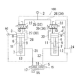
- FIG. 1 is a schematic view showing a hydraulic pressure driving device 100.
- the hydraulic pressure drive device 100 includes a first air-liquid converter (empty-liquid conversion means) 3 and a second air-liquid converter (empty-liquid conversion means) 4 that convert the air pressure supplied from the air pressure source 2 into hydraulic pressure.
- a hydraulic actuator 5 operated by both air-liquid converters 3 and 4 is provided.
- the hydraulic drive device 100 is not particularly limited in use, but is used, for example, in a robot having joints used in food processing.
- the first air-liquid converter 3 and the second air-liquid converter 4 are air hydro boosters having the same configuration as each other.
- the air hydro booster is an air-liquid booster that converts the air pressure supplied from the air pressure source 2 into an increased hydraulic pressure.
- the air-liquid transducers 3 and 4 have two hollow cylinders 6 and 7 having different inner diameters, a piston 8 reciprocally provided in the cylinder 6, and a rod 9 provided in the piston 8. Of the two cylinders 6 and 7, the cylinder 6 having a large inner diameter is divided into a first pneumatic chamber 10 and a second pneumatic chamber 11 by a piston 8. Further, the hydraulic chamber 12 of the cylinder 7 having a small inner diameter is filled with a working liquid such as water.
- a rod 9 is fixed to the second pneumatic chamber 11 side of the piston 8, and the rod 9 is inserted into a cylinder 7 having a small inner diameter as the piston 8 moves.
- the air pressure source 2 that supplies air to the air-liquid converters 3 and 4 is, for example, a compressor.
- the hydraulic actuator 5 has a hollow cylinder chamber 13, a piston 14 provided in the cylinder chamber 13 so as to be reciprocating, and a rod 15 provided in the piston 14.
- the cylinder chamber 13 is divided into a first pressure chamber 17 and a second pressure chamber 18 by a piston 14.
- the hydraulic actuator 5 is a double-rod type hydraulic cylinder, and the rods 15 are provided so as to project from both end faces of the piston 14.
- the hydraulic actuator 5 may be a single rod type hydraulic cylinder.
- the hydraulic pressure drive device 100 includes an operating state acquisition unit 19 for acquiring the operating state of the hydraulic actuator 5, and a first pneumatic valve 22 provided in a flow path for supplying air from the air pressure source 2 to the first air-liquid converter 3.
- a second pneumatic valve 23 provided in a flow path for supplying air from the pneumatic source 2 to the second air-liquid converter 4, and a control device (control means) 24 for controlling the pneumatic valves 22 and 23 are further provided. ..
- the operating state acquisition unit 19 is the pressure of the first pressure acquisition unit (pressure acquisition means) 20 for acquiring the pressure of the pressure liquid in the first pressure chamber 17 and the pressure of the pressure liquid in the second pressure chamber 18. It has a second pressure acquisition unit (pressure acquisition means) 21 for acquiring the above pressure.
- the pressure acquisition units 20 and 21 are pressure gauges that detect and acquire pressure.
- the acquisition results (pressure values) of the pressure acquisition units 20 and 21 are output to the control device 24.
- the pneumatic valves 22 and 23 are servo valves that adjust the flow rate of air from the pneumatic source 2 and supply them to the air-liquid converters 3 and 4.
- the air pressure source 2 is provided with a bifurcated path 25 and a path 26.
- the path 25 is connected to the first pneumatic valve 22, and one end of the path 27 is connected to the first pneumatic valve 22.
- the other end of the path 27 is connected to the first pneumatic chamber 10 of the first air-liquid transducer 3.
- one end of the path 28 is connected to the first pneumatic valve 22, and the other end of the path 28 is connected to the second pneumatic chamber 11 of the first air-liquid transducer 3.
- the path 26 is connected to the second pneumatic valve 23.
- the connection between the second pneumatic valve 23 and the second air-liquid converter 4 is the same as the connection between the first pneumatic valve 22 and the first air-liquid converter 3. That is, the second pneumatic valve 23 and the first pneumatic chamber 10 of the second air pressure converter 4 are connected via a path 29 corresponding to the path 27, and the second pneumatic valve 23 and the second air pressure converter 4 are connected.
- the second pneumatic chamber 11 is connected via a path 30 corresponding to the path 28.
- the first air-liquid converter 3 and the first pressure chamber 17 of the hydraulic actuator 5 are first to supply pressure liquid from the first air-liquid converter 3 to the first pressure chamber 17. It is connected via the hydraulic path 31. Specifically, one end of the first hydraulic passage 31 is connected to a cylinder 7 having a small inner diameter of the first air-liquid converter 3, and the other end is connected to the first pressure chamber 17.
- the first hydraulic passage 31 is provided with a first pressure acquisition unit 20.
- the cylinder 7 having a small inner diameter of the second air-liquid converter 4 and the second pressure chamber 18 of the hydraulic actuator 5 are the second hydraulic pressure for supplying the pressure liquid from the second air-liquid converter 4 to the second pressure chamber 18. It is connected via the road 32.
- the second hydraulic passage 32 is provided with a second pressure acquisition unit 21.
- the first pressure acquisition unit 20 and the second pressure acquisition unit 21 may be provided in the first pressure chamber 17 and the second pressure chamber 18, respectively.
- the control device 24 controls the first pneumatic valve 22 and the second pneumatic valve 23 based on the acquisition results of the pressure acquisition units 20 and 21, and transfers the pressure liquid from the air-liquid transducers 3 and 4 to the hydraulic actuator 5. Control the supply.
- the pressure acquisition units 20 and 21 and the pneumatic valves 22 and 23 are electrically connected to the control device 24.
- the control device 24 is composed of a microcomputer having a central arithmetic unit (CPU), a read-only memory (ROM), a random access memory (RAM), and an input / output interface (I / O interface).
- the control device 24 can also be composed of a plurality of microcomputers.
- the control device 24 controls the hydraulic actuator 5 by, for example, feedback control based on the acquisition results of the pressure acquisition units 20 and 21.
- the compressor which is the air pressure source 2
- the configurations of the air-liquid converters 3 and 4 are similar to each other, the configuration of supplying air from the air pressure source 2 to the air-liquid converters 3 and 4 is also the same, and the configurations of the air-liquid converters 3 are also the same. Since the configurations for supplying the pressure liquid from the hydraulic actuators 5 to the hydraulic actuators 5 are the same, the operation of the first air-liquid converter 3 side of the air-liquid converters 3 and 4 will be described. In the first embodiment, air is supplied to the air-liquid converters 3 and 4 from a common air pressure source 2.
- the air pressure source 2 and the first air pressure chamber 10 of the first air-liquid converter 3 communicate with each other via the paths 25 and 27, and the air pressure source 2 Air is supplied to the first pneumatic chamber 10 through the first pneumatic valve 22. That is, when air is supplied from the air pressure source 2 to the first air pressure chamber 10 of the first air pressure converter 3, the paths 25 and 27 are channels for supplying air from the air pressure source 2 to the first air pressure chamber 10. It becomes a certain first air supply passage 33.
- the second pneumatic chamber 11 of the first air-liquid transducer 3 and the first pneumatic valve 22 communicate with each other via the path 28.
- the second pneumatic chamber 11 communicates with the outside. Therefore, when air is supplied from the air pressure source 2 to the first air pressure chamber 10 through the first air supply passage 33, the piston 8 moves in the direction of expanding the first air pressure chamber 10 (lower side of FIG. 1). At this time, the air in the second pneumatic chamber 11 is discharged to the outside from the first pneumatic valve 22 through the path 28.
- the hydraulic fluid in the hydraulic pressure chamber 12 is supplied as a pressure-increased pressure liquid to the first pressure chamber 17 of the hydraulic actuator 5 through the first hydraulic pressure passage 31.
- the hydraulic fluid in the hydraulic chamber 12 is increased in pressure because the pressure receiving area of the rod 9 (the area of the portion of the rod 9 that pushes out the hydraulic fluid in the hydraulic chamber 12) is the pressure receiving area of the piston 8 (in the piston 8). This is because, for example, it is R times smaller than the area of the portion that receives air pressure).
- the hydraulic fluid in the hydraulic chamber 12 of the first air-liquid converter 3 is pressure-fed to the first pressure chamber 17 of the hydraulic actuator 5 through the first hydraulic passage 31. If the piston 14 of the hydraulic actuator 5 stops and does not move, the pressure in the hydraulic chamber 12 becomes R times. On the contrary, if there is no load on the hydraulic actuator 5, the piston 14 moves to the right in FIG. The pressure in the hydraulic chamber 12 is determined by the load of the hydraulic actuator 5.
- the case of the first air-liquid converter 3 has been described, but the same applies to the case of the second air-liquid converter 4. That is, when air is supplied from the air pressure source 2 to the second air-liquid converter 4 through the second air supply passage 34 including the paths 26 and 29, the hydraulic fluid in the hydraulic chamber 12 of the second air-liquid converter 4 Is supplied to the second pressure chamber 18 of the hydraulic actuator 5 through the second hydraulic passage 32 as the pressure-increased pressure liquid.
- the differential pressure between the first pressure chamber 17 and the second pressure chamber 18 acts on the piston 14, and a load is further applied to the piston 14 to cause the piston. 14 accelerations are determined. Therefore, the piston 14 of the hydraulic actuator 5 is driven by the hydraulic pressure of both air-liquid converters 3 and 4.
- the direction in which the rod 9 enters the hydraulic chamber 12 through the piston 8 by communicating the air pressure source 2 and the first pneumatic chamber 10 (lower part of FIG. 1). ) Can be moved.
- the air pressure source 2 and the second pneumatic chamber 11 may be communicated with each other.
- the air pressure source 2 is driven and the first air pressure valve 22 is operated so that the air pressure source 2 and the second air pressure chamber 11 of the first air pressure converter 3 communicate with each other through the paths 25 and 28, and the air pressure source 2 Air is supplied to the second pneumatic chamber 11 through the first pneumatic valve 22.
- the first pneumatic chamber 10 of the first air-liquid transducer 3 and the first pneumatic valve 22 communicate with each other through the path 27, and the first pneumatic chamber 10 communicates with the outside. Therefore, when air is supplied from the air pressure source 2 to the second air pressure chamber 11, the piston 8 moves in the direction of expanding the second air pressure chamber 11 (upper in FIG. 1). At this time, the air in the first pneumatic chamber 10 is discharged to the outside from the first pneumatic valve 22 through the path 27.
- the series of operations of the hydraulic actuator 5 as described above are executed by the control device 24.
- the control device 24 controls the pneumatic valves 22 and 23 based on the acquisition results of the pressure acquisition units 20 and 21 to control the supply of the pressure liquid to the pressure chambers 17 and 18 of the hydraulic actuator 5. Specifically, target values of the pressure of the pressure liquid in the first pressure chamber 17 and the pressure of the pressure liquid in the second pressure chamber 18 are set, and feedback control is performed so that the piston 14 follows those target values. .. At that time, since the speed and the load of the piston 14 are switched between positive and negative, the pneumatic valves 22 and 23 are appropriately driven according to the required speed and the magnitude and direction of the load. In this way, the differential pressure is monitored by the pressure acquisition units 20 and 21, and the pneumatic valves 22 and 23 are operated according to the differential pressure to operate the hydraulic actuator 5 so that the rod 15 reciprocates.
- the conversion from air pressure to hydraulic pressure is a kind of speed reducer, and the flow rate of the hydraulic fluid is 1 / R of the flow rate of air. Therefore, the precision is improved by R times as compared with the case where the actuator is directly driven only by the pneumatic valve. Further, the air pressure is at most 1 MPa, but when R is 10, a liquid pressure of 10 MPa can be obtained.
- the hydraulic pressure actuator 5 is supplied with a pressure liquid from the air-liquid converters 3 and 4 that convert the air pressure into the hydraulic pressure. Therefore, it is possible to reduce the cost of the hydraulic drive device for obtaining a practical hydraulic pressure as compared with the case of using a conventional hydraulic pump, hydraulic servo valve, or the like. Further, in the hydraulic pressure drive device 100, since the hydraulic pressure actuator 5 can be reciprocated by the air-liquid converters 3 and 4, the reciprocating movement of the hydraulic pressure actuator 5 can be smoothed.
- the air-liquid converters 3 and 4 are air hydro boosters having the same configuration as each other, a simple configuration can be achieved. Further, in the hydraulic pressure drive device 100, the supply of the pressure liquid to the pressure chambers 17 and 18 of the hydraulic actuator 5 is controlled based on the acquisition signals of the pressure acquisition units 20 and 21. Therefore, both rod type hydraulic actuators 5 can be easily controlled. Moreover, since the hydraulic pressure drive device 100 controls the pneumatic valves 22 and 23 to control the supply of the pressure liquid to the pressure chambers 17 and 18, the control of the hydraulic actuator 5 can be realized with an inexpensive configuration. ..
- both pressure chambers 17 and 18 of the hydraulic pressure actuator 5 are constantly pressurized, cavitation can be suppressed.
- the pneumatic valves 22 and 23 are servo valves, the flow rate of air to the air-liquid converters 3 and 4 can be easily controlled.
- FIG. 2 is a schematic view showing the hydraulic pressure drive device 200.
- the hydraulic pressure drive device 200 according to the second embodiment is basically the same as the hydraulic pressure drive device 100 according to the first embodiment. Therefore, in the following, the differences between the two will be mainly described, and the corresponding configurations will be described with the same reference numerals. Further, the description of common matters in the first and second embodiments will be omitted.
- the air-liquid converters 3 and 4 were air hydro boosters, but in the second embodiment, the air-liquid converters 3 and 4 are air hydro converters.
- the air-liquid converters 3 and 4 are air hydroconverters having the same configuration as each other.
- the air hydroconverter is an air-liquid converter that converts the air pressure supplied from the air pressure source 2 into a hydraulic pressure.
- the air-liquid transducers 3 and 4 include a hollow cylinder 35 and a piston 36 reciprocally provided in the cylinder 35. The inside of the cylinder 35 is divided into an air chamber 37 and a liquid chamber 38 by a piston 36, and the liquid chamber 38 is filled with a working liquid such as water.
- one of the bifurcated flow paths from the air pressure source 2 is the first air supply passage 33, and the first air supply passage 33 is the air chamber 37 of the first air-liquid converter 3. Connected to.
- the other of the bifurcated flow paths is the second air supply passage 34, and the second air supply passage 34 is connected to the air chamber 37 of the second air-liquid converter 4.
- the first pneumatic valve 22 provided in the first air supply passage 33 and the second pneumatic valve 23 provided in the second air supply passage 34 are the air pressures supplied from the air pressure source 2 to the air chamber 37.
- An electropneumatic regulator is a device that adjusts the air pressure in proportion to the input that is an electric signal.
- the liquid chamber 38 of the first air-liquid converter 3 and the first pressure chamber 17 of the hydraulic actuator 5 are connected to each other via the first hydraulic passage 31, while being connected to the liquid chamber 38 of the second air-liquid converter 4.
- the hydraulic actuator 5 is connected to the second pressure chamber 18 via the second hydraulic passage 32.
- the hydraulic pressure drive device 200 includes a first liquid supply valve 39, a second liquid supply valve 40, and a small-capacity hydraulic pressure pump 41 in addition to the configuration of the hydraulic pressure drive device 100 according to the first embodiment.
- the first liquid supply valve 39 is provided in the first hydraulic pressure passage 31, and the second liquid supply valve 40 is provided in the second hydraulic pressure passage 32.
- the liquid supply valves 39 and 40 are solenoid valves that can be switched on and off, and a check that allows only the flow of fluid from each of the air-liquid converters 3 and 4 to the hydraulic actuator 5.
- a valve 42 is built in.
- the hydraulic pump 41 is a small servo pump, which is configured to be rotatable in both directions by an electric motor such as a servo motor 43, and can be selected and rotated in the forward and reverse directions.
- the hydraulic pump 41 is connected to the first pressure chamber 17 of the hydraulic actuator 5 via the first auxiliary passage 44, and is connected to the second pressure chamber 18 of the hydraulic actuator 5 via the second auxiliary passage 45. Will be done.
- a part of the first hydraulic passage 31 and the first auxiliary passage 44 is a common passage on the first pressure chamber 17 side of the hydraulic actuator 5.
- the first pressure acquisition unit 20 is provided in a common path between the first hydraulic path 31 and the first auxiliary path 44, and the first liquid supply valve 39 is provided in the first hydraulic path 31 on the upstream side of the common path.
- a part of the second hydraulic passage 32 and the second auxiliary passage 45 is a common passage on the second pressure chamber 18 side of the hydraulic actuator 5.
- the second pressure acquisition unit 21 is provided in the common path between the second hydraulic path 32 and the second auxiliary path 45, and the second liquid supply valve 40 is in the second hydraulic path 32 on the upstream side of the common path.
- control device 24 controls the pneumatic valves 22 and 23 based on the acquisition results of the pressure acquisition units 20 and 21 to supply the pressure liquid to the pressure chambers 17 and 18 of the hydraulic actuator 5. Control. This control is the same as the feedback control of the first embodiment.
- control device 24 also controls the hydraulic pump 41 based on the acquisition results of the pressure acquisition units 20 and 21.
- the liquid supply valves 39 and 40 and the servomotor 43 of the hydraulic pump 41 are electrically connected to the control device 24.
- the hydraulic actuator 5 may be operated at a high speed, or the hydraulic actuator 5 may be operated at a low speed.
- the rod 15 of the hydraulic actuator 5 reciprocates quickly with a low load.
- the rod 15 of the hydraulic actuator 5 slowly reciprocates under a high load.
- air-liquid transducers 3 and 4 are used.
- the control device 24 drives the air-liquid converters 3 and 4 with the hydraulic pump 41 stopped and the liquid supply valves 39 and 40 open.
- the pressure of the hydraulic actuator 5 to the pressure chambers 17 and 18 is controlled by controlling the pneumatic valves 22 and 23 based on the acquisition results of the pressure acquisition units 20 and 21. Control the supply of liquid.
- the air-liquid converters 3 and 4 are air hydroconverters.
- the piston 36 moves in the direction of expanding the air chamber 37 (lower part of FIG. 2). ..
- the hydraulic fluid in the liquid chamber 38 of the first air-liquid converter 3 is supplied as a pressure liquid to the first pressure chamber 17 of the hydraulic actuator 5 through the first hydraulic passage 31.
- the hydraulic actuator 5 is supplied from the second air-liquid converter 4 through the second hydraulic passage 32.
- the pressure liquid is supplied to the second pressure chamber 18 of the above.
- the hydraulic pump 41 is used during low-speed driving with a high load.
- the control device 24 drives the hydraulic pump 41 with the liquid supply valves 39 and 40 closed.
- target values of the pressure of the pressure liquid in the first pressure chamber 17 and the pressure of the pressure liquid in the second pressure chamber 18 are set, and feedback control is performed so that the piston 14 follows those target values. ..
- the hydraulic pump 41 is appropriately driven according to the required speed and the magnitude and direction of the load. In this way, the hydraulic pump 41 is controlled based on the acquisition results of the pressure acquisition units 20 and 21.
- the required differential pressure can be applied to the piston 14 by closing the liquid supply valves 39 and 40 and driving the hydraulic pump 41.
- the hydraulic actuator 5 can be operated by the small hydraulic pump 41, as compared with the case where the hydraulic actuator 5 is operated by the air hydroconverter, it is compared with the case where the hydraulic actuator 5 is operated by the air hydroconverter.
- the hydraulic actuator 5 can be controlled more precisely.
- the air-liquid converters 3 and 4 are air hydroconverters having the same configuration as each other, a simple configuration can be achieved.
- the check valves 42 are built in the liquid supply valves 39 and 40, and the pressure chambers 17 and 18 of the hydraulic actuator 5 do not fall below the air pressure of the air chamber 37, so that cavitation is performed. It can be suppressed.
- FIG. 3 is a schematic view showing the hydraulic pressure drive device 201.
- the points different from the hydraulic drive device 200 will be mainly described, and the above-mentioned ones are applied to other configurations and controls.
- the hydraulic cylinder 46 and its driving device (driving means) 47 are provided in place of the hydraulic pump 41 used in the hydraulic driving device 200 according to the second embodiment.
- the hydraulic cylinder 46 has a hollow cylinder body 48 and a movable piston 49 reciprocally provided in the cylinder body 48.
- the inside of the cylinder body 48 is divided into a first liquid chamber 50 and a second liquid chamber 51 by a movable piston 49, and the first liquid chamber 50 and the second liquid chamber 51 are filled with a working liquid such as water. ing.
- the first liquid chamber 50 is connected to the first pressure chamber 17 of the hydraulic actuator 5 via the first auxiliary passage 44
- the second liquid chamber 51 is connected to the first pressure chamber 17 of the hydraulic actuator 5 via the second auxiliary passage 45.
- the drive device 47 is a means for reciprocating the movable piston 49 of the hydraulic cylinder 46, and is a small motor in this modification.
- the drive device 47 is connected to the movable piston 49 of the hydraulic cylinder 46 via the rod 52.
- control device 24 controls the pneumatic valves 22 and 23 based on the detection results of the pressure acquisition units 20 and 21 as in the feedback control of the second embodiment, thereby controlling the pressure of the hydraulic actuator 5.
- the supply of the pressure liquid to the chambers 17 and 18 is controlled.
- control device 24 also controls the drive device 47 of the hydraulic cylinder 46 based on the acquisition result of the pressure acquisition unit.
- the drive device 47 of the hydraulic cylinder 46 is electrically connected to the control device 24.
- the hydraulic actuator 201 may be driven at high speed with a low load of the hydraulic actuator 5 or may be driven at low speed with a high load of the hydraulic actuator 5.
- the hydraulic actuator 5 is operated by the air-liquid converters 3 and 4, as in the case of high-speed driving of the hydraulic pressure driving device 200.
- the control device 24 drives the air-liquid converters 3 and 4 with the drive device 47 of the hydraulic cylinder 46 stopped and the liquid supply valves 39 and 40 open.
- the hydraulic cylinder 46 is used.
- the control device 24 drives the drive device 47 with the liquid supply valves 39 and 40 closed to reciprocate the movable piston 49 of the hydraulic cylinder 46.
- target values of the pressure of the pressure liquid in the first pressure chamber 17 and the pressure of the pressure liquid in the second pressure chamber 18 are set, and feedback control is performed so that the piston 14 follows those target values. ..
- the drive device 47 is appropriately driven according to the required speed and the magnitude and direction of the load. In this way, the drive device 47 is controlled based on the acquisition results of the pressure acquisition units 20 and 21.
- the movable piston 49 of the hydraulic cylinder 46 reciprocates to supply the hydraulic fluid from the first liquid chamber 50 to the first pressure chamber 17, and the hydraulic fluid is supplied from the second liquid chamber 51 to the second pressure chamber 18. Is supplied.
- the volume of the cylinder body 48 of the hydraulic cylinder 46 is sufficiently smaller than the volume of the cylinder chamber 13 of the hydraulic actuator 5 in order to secure the necessary differential pressure acting on the piston 14.
- the hydraulic actuator 5 can be operated by the hydraulic cylinder 46 and the drive device 47 thereof. Therefore, the flow rate of the hydraulic fluid supplied to the hydraulic actuator 5 by the hydraulic cylinder 46 can be adjusted to a small amount, and the hydraulic actuator 5 can be operated as compared with the case where the hydraulic actuator 5 is operated by the air hydroconverter. It can be controlled more precisely.
- the pneumatic valves 22 and 23 are servo valves, but they may be electropneumatic regulators.
- one is the first air supply passage 33 connected to the first air pressure chamber 10 of the first air pressure transducer 3, and the other is the second air liquid.
- the second pneumatic chamber 11 of the air-liquid converters 3 and 4 is configured so that the air inside can be opened to the outside.
- the hydraulic pump 41 of the second embodiment the hydraulic cylinder 46 of the modified example, and the driving device 47 thereof may be provided.
- the air-liquid converters 3 and 4 are air hydro boosters, and in the second embodiment and the modified example, the air-liquid converters 3 and 4 are air hydro converters.
- one of the air-liquid converters 3 and 4 may be an air hydro booster and the other may be an air hydro converter.
- the mode in which the pressure acquisition units 20 and 21 for acquiring the pressure of the pressure liquid in the pressure chambers 17 and 18 detect and acquire the pressure has been described.
- the pressure acquisition unit instead of detecting the pressure of the pressure liquid in the pressure chambers 17 and 18, the pressure of the pressure liquid in the pressure chambers 17 and 18 may be acquired by calculation.
- the pressure gauges provided in the hydraulic passages 31 and 32 are abolished, and the pressure gauges 60 and 61 for detecting the pressure of the air in the pneumatic chamber 10 are installed in the air-liquid converters 3 and 4, respectively.
- the pressure gauges 60 and 61 may be provided and the detected values of the pressure gauges 60 and 61 may be output to the control device 24, and the control device 24 may calculate the pressure of the pressure liquid in the pressure chambers 17 and 18 based on the detected values of the pressure gauges 60 and 61. .. Specifically, the control device 24 adds the pressure loss in the hydraulic passages 31 and 32 to the equilibrium equation of the force determined from the detected values of the pressure gauges 60 and 61 and the pressure receiving areas of the piston 8 and the rod 9. Then, the pressure of the pressure liquid in the pressure chambers 17 and 18 is calculated.
- control device 24 since the control device 24 is configured to acquire the pressure of the pressure liquid in the pressure chambers 17 and 18 by calculation, it corresponds to the operating state acquisition unit in which the control device 24 acquires the operating state of the hydraulic actuator 5. ..
- FIG. 4 shows a modified example of the hydraulic drive device 100, but this modified example can also be applied to the hydraulic drive devices 200 and 201.
- the control device 24 may control the pneumatic valves 22 and 23 based on the pressure of the pressure liquid in the pressure chambers 17 and 18 and the position of the rod 15. Specifically, target values of the pressure of the pressure liquid in the first pressure chamber 17 and the pressure of the pressure liquid in the second pressure chamber 18 are set, and feedback control is performed so that the piston 14 follows those target values. At the same time, a target value of the position of the rod 15 is set, and feedback control is performed so that the piston 14 follows the target value.
- the accuracy of control of the hydraulic actuator 5 is improved.
- the position of the rod 15 is acquired by the position acquisition unit 62 that detects the position of the rod 15.
- the position acquisition unit 62 is, for example, a stroke sensor provided in the hydraulic actuator 5.
- the acquisition result of the position acquisition unit 62 is output to the control device 24.
- the pressure acquisition units 20 and 21 and the position acquisition unit 62 correspond to the operation state acquisition unit 19 that acquires the operation state of the hydraulic actuator 5.
- the position of the rod 15 may be acquired by calculation.
- the position acquisition unit 62 provided in the hydraulic actuator 5 is abolished, and position detection units for detecting the position of the piston 8 are provided in each of the air-liquid converters 3 and 4.
- the detection value of the position detection unit may be output to the control device 24, and the position of the rod 15 may be calculated in the control device 24 based on the detection value of the position detection unit.
- the control device 24 uses the hydraulic passages 31 and 32 in a volume-conserving manner determined by the position of the piston 8 detected by the position detection unit and the pressure receiving areas of the piston 8, the rod 9, and the piston 14.
- the position of the rod 15 is calculated in consideration of the flow rate loss and the like.
- a rod protruding to the outside of the cylinder 6 may be attached to the piston 8 and a stroke sensor for detecting the position of the rod may be provided on the cylinder 6.
- a magnet may be attached to the piston 8 and a magnetic sensor for detecting the position of the piston 8 in a non-contact manner may be provided in the cylinder 6.
- control device 24 since the control device 24 is configured to acquire the position of the rod 15 by calculation, it corresponds to the operating state acquisition unit in which the control device 24 acquires the operating state of the hydraulic actuator 5.
- a modification of the hydraulic drive device 100 shown in FIG. 5 is shown, but this modification can also be applied to the hydraulic drive devices 200 and 201.
- a position detection unit for detecting the position of the piston 36 may be provided in each of the air-liquid converters 3 and 4, and the hydraulic pressure drive device 201 shown in FIG. 3 may be provided.
- the hydraulic cylinder 46 may be provided with a position detection unit for detecting the position of the movable piston 49.
- the control device 24 may control the pneumatic valves 22 and 23 based on the pressure of the pressure liquid in the pressure chambers 17 and 18 and the load acting on the rod 15. Specifically, target values of the pressure of the pressure liquid in the first pressure chamber 17 and the pressure of the pressure liquid in the second pressure chamber 18 are set, and feedback control is performed so that the piston 14 follows those target values. At the same time, a target value of the load of the rod 15 is set, and feedback control is performed so that the piston 14 follows the target value.
- the control device 24 may control the pneumatic valves 22 and 23 based on the pressure of the pressure liquid in the pressure chambers 17 and 18, the position of the rod 15, and the load acting on the rod 15.
- the load of the rod 15 is acquired by a load acquisition unit that detects the load of the rod 15.
- the load acquisition unit is, for example, a load sensor provided on the hydraulic actuator 5.
- the acquisition result of the load acquisition unit is output to the control device 24.
- the load acquisition unit also corresponds to the operating state acquisition unit 19 that acquires the operating state of the hydraulic actuator 5.
- the load of the rod 15 may be acquired by calculation.
- the control device 24 calculates the differential pressure acting on the piston 14 based on the acquisition results of the pressure acquisition units 20 and 21, and calculates the load of the rod 15 from the differential pressure and the pressure receiving area of the piston 14. Further, as described in (4) above, when the control device 24 calculates the pressure of the pressure liquid in the pressure chambers 17 and 18 based on the pressure of the air in the pneumatic chamber 10, the control device 24 calculates the pressure. The differential pressure acting on the piston 14 is calculated from the obtained pressure liquids in the pressure chambers 17 and 18, and the load on the rod 15 is calculated from the differential pressure and the pressure receiving area of the piston 14. In this way, when the load of the rod 15 is acquired by calculation, the control device 24 corresponds to the operating state acquisition unit that acquires the operating state of the hydraulic actuator 5.
- the pressure liquid from the first air-liquid converter 3 is supplied to the first pressure chamber 17 of the hydraulic actuator 5, while the second pressure chamber 18 of the hydraulic actuator 5 is supplied.
- the hydraulic actuator 5 can be smoothly reciprocated. Further, the supply of the pressure liquid to the hydraulic actuator 5 is controlled based on the acquisition result of the operating state acquisition unit 19 that acquires the operating state of the hydraulic actuator 5. Therefore, the hydraulic actuator 5 of both rod types can be easily controlled, and the reciprocating motion of the hydraulic actuator 5 can be performed with high accuracy.
- the first pneumatic valve 22 and the air pressure source 2 provided in the first air supply passage 33 for supplying air from the air pressure source 2 to the first air-liquid converter 3 to the first.
- the second pneumatic valve 23 provided in the second air supply passage 34 that supplies air to the air-liquid converter 4 is controlled.
- the air-liquid converters 3 and 4 to which air is supplied through such pneumatic valves 22 and 23 are an air hydroconverter or an air hydro booster. Therefore, it is possible to control the supply of air to the air-liquid converters 3 and 4 and the reciprocating movement of the hydraulic actuator 5 with an inexpensive configuration.
- the hydraulic pressure pump 41 that can rotate in both directions is connected to the first pressure chamber 17 via the first auxiliary passage 44, and is second via the second auxiliary passage 45. It is connected to the pressure chamber 18. Therefore, since the hydraulic actuator 5 can be operated by driving the hydraulic pump 41, more precise control of the hydraulic actuator 5 can be performed.
- the hydraulic pressure drive device 201 includes a hydraulic cylinder 46 and a drive device 47 thereof.
- the first liquid chamber 50 is connected to the first pressure chamber 17 via the first auxiliary passage 44
- the second liquid chamber 51 is connected to the second pressure chamber 18 via the second auxiliary passage 45.
- the drive device 47 is a means for reciprocating the movable piston 49 in the hydraulic cylinder 46. Therefore, since the movable piston 49 of the hydraulic cylinder 46 can be reciprocated by the drive device 47 to operate the hydraulic actuator 5, more precise control of the hydraulic actuator 5 can be performed.
- the flow rate or pressure of air to the air-liquid converters 3 and 4 can be determined. Can be adjusted.
Abstract
Priority Applications (3)
| Application Number | Priority Date | Filing Date | Title |
|---|---|---|---|
| CN202080070590.9A CN114729652A (zh) | 2019-10-07 | 2020-10-06 | 液压驱动装置 |
| JP2021551669A JP7195557B2 (ja) | 2019-10-07 | 2020-10-06 | 液圧駆動装置 |
| US17/754,558 US20240060515A1 (en) | 2019-10-07 | 2020-10-06 | Fluid pressure driving device |
Applications Claiming Priority (2)
| Application Number | Priority Date | Filing Date | Title |
|---|---|---|---|
| JP2019184405 | 2019-10-07 | ||
| JP2019-184405 | 2019-10-07 |
Publications (1)
| Publication Number | Publication Date |
|---|---|
| WO2021070828A1 true WO2021070828A1 (fr) | 2021-04-15 |
Family
ID=75437481
Family Applications (1)
| Application Number | Title | Priority Date | Filing Date |
|---|---|---|---|
| PCT/JP2020/037901 WO2021070828A1 (fr) | 2019-10-07 | 2020-10-06 | Dispositif d'entraînement hydraulique |
Country Status (4)
| Country | Link |
|---|---|
| US (1) | US20240060515A1 (fr) |
| JP (1) | JP7195557B2 (fr) |
| CN (1) | CN114729652A (fr) |
| WO (1) | WO2021070828A1 (fr) |
Cited By (1)
| Publication number | Priority date | Publication date | Assignee | Title |
|---|---|---|---|---|
| US11703066B2 (en) | 2021-11-11 | 2023-07-18 | Foi Group, Inc. | Hydraulic power pack system |
Citations (3)
| Publication number | Priority date | Publication date | Assignee | Title |
|---|---|---|---|---|
| JPS58124804A (ja) * | 1982-01-19 | 1983-07-25 | Konan Denki Kk | 流体圧アクチユエ−タの操作装置 |
| JPS61142902U (fr) * | 1985-02-27 | 1986-09-03 | ||
| JP2015096757A (ja) * | 2013-11-15 | 2015-05-21 | 学校法人立命館 | 液圧駆動装置 |
Family Cites Families (3)
| Publication number | Priority date | Publication date | Assignee | Title |
|---|---|---|---|---|
| JPS62176502U (fr) * | 1986-04-30 | 1987-11-10 | ||
| JPH0925903A (ja) * | 1995-07-12 | 1997-01-28 | Daido Steel Co Ltd | 同調駆動装置 |
| JP6164528B2 (ja) | 2014-03-20 | 2017-07-19 | 学校法人立命館 | 液圧駆動装置 |
-
2020
- 2020-10-06 WO PCT/JP2020/037901 patent/WO2021070828A1/fr active Application Filing
- 2020-10-06 JP JP2021551669A patent/JP7195557B2/ja active Active
- 2020-10-06 CN CN202080070590.9A patent/CN114729652A/zh active Pending
- 2020-10-06 US US17/754,558 patent/US20240060515A1/en active Pending
Patent Citations (3)
| Publication number | Priority date | Publication date | Assignee | Title |
|---|---|---|---|---|
| JPS58124804A (ja) * | 1982-01-19 | 1983-07-25 | Konan Denki Kk | 流体圧アクチユエ−タの操作装置 |
| JPS61142902U (fr) * | 1985-02-27 | 1986-09-03 | ||
| JP2015096757A (ja) * | 2013-11-15 | 2015-05-21 | 学校法人立命館 | 液圧駆動装置 |
Cited By (1)
| Publication number | Priority date | Publication date | Assignee | Title |
|---|---|---|---|---|
| US11703066B2 (en) | 2021-11-11 | 2023-07-18 | Foi Group, Inc. | Hydraulic power pack system |
Also Published As
| Publication number | Publication date |
|---|---|
| JPWO2021070828A1 (fr) | 2021-04-15 |
| CN114729652A (zh) | 2022-07-08 |
| US20240060515A1 (en) | 2024-02-22 |
| JP7195557B2 (ja) | 2022-12-26 |
Similar Documents
| Publication | Publication Date | Title |
|---|---|---|
| US4666374A (en) | Methods and apparatus for producing uniform discharge and suction flow rates | |
| US20070120662A1 (en) | Digital hydraulic system | |
| JP6234439B2 (ja) | 圧力伝達用ハイドロニューマチック装置及びリベット打ち機 | |
| US3407601A (en) | Air-hydraulic system and apparatus | |
| US11085466B2 (en) | Electrohydraulic system for use under water, comprising an electrohydraulic actuator | |
| CN103233932B (zh) | 一种高集成性液压驱动单元结构 | |
| JP2008249025A (ja) | 複動形エアシリンダの位置決め制御機構 | |
| JPH02161183A (ja) | ダイヤフラムポンプの油圧回路制御装置 | |
| US8973890B2 (en) | Fluid-operated actuating drive on a valve | |
| JP2015518429A5 (fr) | ||
| US6594992B1 (en) | Punch press hydraulic servo device using a rotary valve | |
| WO2021070828A1 (fr) | Dispositif d'entraînement hydraulique | |
| JP6164528B2 (ja) | 液圧駆動装置 | |
| US8833391B2 (en) | Valve arrangement | |
| US6957567B2 (en) | Method and system for the controlled application of fluid pressure to a load, especially for pressure testing pipe | |
| US6834522B2 (en) | High internal pressure forming process | |
| KR101123040B1 (ko) | 유압 편로드 실린더를 구비한 산업용 전기유압 일체형 구동기 시스템 | |
| CN113417898B (zh) | 一种基于电磁比例阀的电液执行器系统及其位移控制方法 | |
| JPWO2021070828A5 (fr) | ||
| CN108087351B (zh) | 电动液压的装置和液压轴 | |
| JP2016114151A (ja) | 液圧装置および液圧装置の制御方法 | |
| JP2015096757A (ja) | 液圧駆動装置 | |
| WO2023106037A1 (fr) | Transmission hydraulique | |
| JP2014130076A (ja) | 材料試験機 | |
| RU2683349C1 (ru) | Агрегат для зарядки пневмогидравлических аккумуляторов азотом |
Legal Events
| Date | Code | Title | Description |
|---|---|---|---|
| 121 | Ep: the epo has been informed by wipo that ep was designated in this application |
Ref document number: 20873983 Country of ref document: EP Kind code of ref document: A1 |
|
| ENP | Entry into the national phase |
Ref document number: 2021551669 Country of ref document: JP Kind code of ref document: A |
|
| WWE | Wipo information: entry into national phase |
Ref document number: 17754558 Country of ref document: US |
|
| NENP | Non-entry into the national phase |
Ref country code: DE |
|
| 122 | Ep: pct application non-entry in european phase |
Ref document number: 20873983 Country of ref document: EP Kind code of ref document: A1 |