WO2021070643A1 - 近接露光装置用照明装置、ledユニット、近接露光装置及び近接露光装置の露光方法 - Google Patents
近接露光装置用照明装置、ledユニット、近接露光装置及び近接露光装置の露光方法 Download PDFInfo
- Publication number
- WO2021070643A1 WO2021070643A1 PCT/JP2020/036432 JP2020036432W WO2021070643A1 WO 2021070643 A1 WO2021070643 A1 WO 2021070643A1 JP 2020036432 W JP2020036432 W JP 2020036432W WO 2021070643 A1 WO2021070643 A1 WO 2021070643A1
- Authority
- WO
- WIPO (PCT)
- Prior art keywords
- light source
- source unit
- light
- proximity exposure
- moving mechanism
- Prior art date
- Legal status (The legal status is an assumption and is not a legal conclusion. Google has not performed a legal analysis and makes no representation as to the accuracy of the status listed.)
- Ceased
Links
Images






Classifications
-
- G—PHYSICS
- G03—PHOTOGRAPHY; CINEMATOGRAPHY; ANALOGOUS TECHNIQUES USING WAVES OTHER THAN OPTICAL WAVES; ELECTROGRAPHY; HOLOGRAPHY
- G03F—PHOTOMECHANICAL PRODUCTION OF TEXTURED OR PATTERNED SURFACES, e.g. FOR PRINTING, FOR PROCESSING OF SEMICONDUCTOR DEVICES; MATERIALS THEREFOR; ORIGINALS THEREFOR; APPARATUS SPECIALLY ADAPTED THEREFOR
- G03F7/00—Photomechanical, e.g. photolithographic, production of textured or patterned surfaces, e.g. printing surfaces; Materials therefor, e.g. comprising photoresists; Apparatus specially adapted therefor
- G03F7/70—Microphotolithographic exposure; Apparatus therefor
- G03F7/70008—Production of exposure light, i.e. light sources
- G03F7/7005—Production of exposure light, i.e. light sources by multiple sources, e.g. light-emitting diodes [LED] or light source arrays
-
- G—PHYSICS
- G03—PHOTOGRAPHY; CINEMATOGRAPHY; ANALOGOUS TECHNIQUES USING WAVES OTHER THAN OPTICAL WAVES; ELECTROGRAPHY; HOLOGRAPHY
- G03F—PHOTOMECHANICAL PRODUCTION OF TEXTURED OR PATTERNED SURFACES, e.g. FOR PRINTING, FOR PROCESSING OF SEMICONDUCTOR DEVICES; MATERIALS THEREFOR; ORIGINALS THEREFOR; APPARATUS SPECIALLY ADAPTED THEREFOR
- G03F7/00—Photomechanical, e.g. photolithographic, production of textured or patterned surfaces, e.g. printing surfaces; Materials therefor, e.g. comprising photoresists; Apparatus specially adapted therefor
- G03F7/20—Exposure; Apparatus therefor
- G03F7/2002—Exposure; Apparatus therefor with visible light or UV light, through an original having an opaque pattern on a transparent support, e.g. film printing, projection printing; by reflection of visible or UV light from an original such as a printed image
- G03F7/2004—Exposure; Apparatus therefor with visible light or UV light, through an original having an opaque pattern on a transparent support, e.g. film printing, projection printing; by reflection of visible or UV light from an original such as a printed image characterised by the use of a particular light source, e.g. fluorescent lamps or deep UV light
-
- G—PHYSICS
- G03—PHOTOGRAPHY; CINEMATOGRAPHY; ANALOGOUS TECHNIQUES USING WAVES OTHER THAN OPTICAL WAVES; ELECTROGRAPHY; HOLOGRAPHY
- G03F—PHOTOMECHANICAL PRODUCTION OF TEXTURED OR PATTERNED SURFACES, e.g. FOR PRINTING, FOR PROCESSING OF SEMICONDUCTOR DEVICES; MATERIALS THEREFOR; ORIGINALS THEREFOR; APPARATUS SPECIALLY ADAPTED THEREFOR
- G03F7/00—Photomechanical, e.g. photolithographic, production of textured or patterned surfaces, e.g. printing surfaces; Materials therefor, e.g. comprising photoresists; Apparatus specially adapted therefor
- G03F7/20—Exposure; Apparatus therefor
-
- G—PHYSICS
- G03—PHOTOGRAPHY; CINEMATOGRAPHY; ANALOGOUS TECHNIQUES USING WAVES OTHER THAN OPTICAL WAVES; ELECTROGRAPHY; HOLOGRAPHY
- G03F—PHOTOMECHANICAL PRODUCTION OF TEXTURED OR PATTERNED SURFACES, e.g. FOR PRINTING, FOR PROCESSING OF SEMICONDUCTOR DEVICES; MATERIALS THEREFOR; ORIGINALS THEREFOR; APPARATUS SPECIALLY ADAPTED THEREFOR
- G03F7/00—Photomechanical, e.g. photolithographic, production of textured or patterned surfaces, e.g. printing surfaces; Materials therefor, e.g. comprising photoresists; Apparatus specially adapted therefor
- G03F7/20—Exposure; Apparatus therefor
- G03F7/2002—Exposure; Apparatus therefor with visible light or UV light, through an original having an opaque pattern on a transparent support, e.g. film printing, projection printing; by reflection of visible or UV light from an original such as a printed image
- G03F7/2008—Exposure; Apparatus therefor with visible light or UV light, through an original having an opaque pattern on a transparent support, e.g. film printing, projection printing; by reflection of visible or UV light from an original such as a printed image characterised by the reflectors, diffusers, light or heat filtering means or anti-reflective means used
-
- G—PHYSICS
- G03—PHOTOGRAPHY; CINEMATOGRAPHY; ANALOGOUS TECHNIQUES USING WAVES OTHER THAN OPTICAL WAVES; ELECTROGRAPHY; HOLOGRAPHY
- G03F—PHOTOMECHANICAL PRODUCTION OF TEXTURED OR PATTERNED SURFACES, e.g. FOR PRINTING, FOR PROCESSING OF SEMICONDUCTOR DEVICES; MATERIALS THEREFOR; ORIGINALS THEREFOR; APPARATUS SPECIALLY ADAPTED THEREFOR
- G03F7/00—Photomechanical, e.g. photolithographic, production of textured or patterned surfaces, e.g. printing surfaces; Materials therefor, e.g. comprising photoresists; Apparatus specially adapted therefor
- G03F7/70—Microphotolithographic exposure; Apparatus therefor
- G03F7/70008—Production of exposure light, i.e. light sources
- G03F7/70016—Production of exposure light, i.e. light sources by discharge lamps
-
- G—PHYSICS
- G03—PHOTOGRAPHY; CINEMATOGRAPHY; ANALOGOUS TECHNIQUES USING WAVES OTHER THAN OPTICAL WAVES; ELECTROGRAPHY; HOLOGRAPHY
- G03F—PHOTOMECHANICAL PRODUCTION OF TEXTURED OR PATTERNED SURFACES, e.g. FOR PRINTING, FOR PROCESSING OF SEMICONDUCTOR DEVICES; MATERIALS THEREFOR; ORIGINALS THEREFOR; APPARATUS SPECIALLY ADAPTED THEREFOR
- G03F7/00—Photomechanical, e.g. photolithographic, production of textured or patterned surfaces, e.g. printing surfaces; Materials therefor, e.g. comprising photoresists; Apparatus specially adapted therefor
- G03F7/70—Microphotolithographic exposure; Apparatus therefor
- G03F7/70058—Mask illumination systems
- G03F7/70075—Homogenization of illumination intensity in the mask plane by using an integrator, e.g. fly's eye lens, facet mirror or glass rod, by using a diffusing optical element or by beam deflection
-
- G—PHYSICS
- G03—PHOTOGRAPHY; CINEMATOGRAPHY; ANALOGOUS TECHNIQUES USING WAVES OTHER THAN OPTICAL WAVES; ELECTROGRAPHY; HOLOGRAPHY
- G03F—PHOTOMECHANICAL PRODUCTION OF TEXTURED OR PATTERNED SURFACES, e.g. FOR PRINTING, FOR PROCESSING OF SEMICONDUCTOR DEVICES; MATERIALS THEREFOR; ORIGINALS THEREFOR; APPARATUS SPECIALLY ADAPTED THEREFOR
- G03F7/00—Photomechanical, e.g. photolithographic, production of textured or patterned surfaces, e.g. printing surfaces; Materials therefor, e.g. comprising photoresists; Apparatus specially adapted therefor
- G03F7/70—Microphotolithographic exposure; Apparatus therefor
- G03F7/70216—Mask projection systems
- G03F7/7035—Proximity or contact printers
Definitions
- the present invention relates to an exposure method for an illumination device, an LED unit, a proximity exposure device, and a proximity exposure device that irradiate a work with exposure light through a mask.
- a discharge lamp such as an ultra-high pressure mercury lamp is used as a light source, and a mask pattern is exposed on a work fixed to a stage by the light emitted from the light source.
- Those that transfer are known.
- the illumination apparatus includes, for example, a main light source composed of a mercury lamp and an auxiliary light source composed of, for example, an LED having different output response characteristics from the main light source. It includes a photoelectric sensor that detects the emission light of the main light source and the auxiliary light source, and an exposure amount control unit that changes the intensity of the exposure light applied to the exposed substrate.
- the main light source emits light with an illuminance determined from the target minimum illuminance
- the auxiliary light source emits the illuminance of the difference between the target illuminance and the illuminance by the main light source
- the light emitted from the main light source and the auxiliary light source by the photosynthesis unit is emitted.
- An exposure apparatus is disclosed that is synthesized to improve the output response characteristics of a light source without reducing the productivity of the apparatus.
- Patent Document 2 includes first and second light source units in which the illumination optical system includes a mercury lamp, an LED, a halogen lamp, and the like, and a filter capable of blocking light from the first light source unit. .. Then, with the substrate and the mask close to a predetermined gap, the substrate is irradiated with light from the first and second light source portions at different timings by controlling the opening timing of the filter to achieve high resolution.
- a proximity exposure apparatus that forms a pattern and improves throughput is disclosed.
- the LED has an advantage that the power consumption is small as compared with the mercury lamp. Therefore, it is desired that the LED can be used as the light source even in the existing exposure device that has already incorporated the lighting device in which the light source is a mercury lamp. In particular, when switching the light source unit from the mercury lamp to the LED, it is necessary to perform a test for matching the conditions through which the sample is actually passed. However, if both light sources can be used together, the mercury lamp can be smoothly switched to the LED.
- the exposure device of Patent Document 1 uses an LED as an auxiliary light source
- the exposure device of Patent Document 2 also uses an LED as an example and selectively uses the first light source unit as the second light source unit. It is used in combination and does not take the above issues into consideration.
- the present invention has been made in view of the above-mentioned problems, and an object of the present invention is a lighting device for a proximity exposure device, an LED unit, and a proximity exposure device that can independently use both a mercury lamp and an LED as a light source unit. And an exposure method of a proximity exposure apparatus.
- An illuminating device that irradiates a work arranged through a mask and a predetermined gap with exposure light through the mask.
- the first light source unit that uses a mercury lamp as the light source, A fly-eye lens that uniformly emits light from the first light source unit, and A plurality of reflectors that reflect light from the first light source unit, and
- the second light source unit using a plurality of LED elements as light sources and the second light source unit are separated from the operating position located on the optical path of the first light source unit and the optical path of the first light source unit.
- An LED unit having a moving mechanism for moving between the retracted position and the retracted position, A lighting device for a proximity exposure device.
- An LED unit used in the lighting device for the proximity exposure device according to (1) is an LED unit installed at a position separated from the optical path of the first light source unit.
- a proximity exposure apparatus comprising the illumination apparatus for the proximity exposure apparatus according to (1), which exposes and transfers a mask pattern to a work by exposure light from the illumination apparatus.
- both the mercury lamp and the LED can be used independently by one lighting device.
- FIG. 1A is a side view showing a schematic configuration of a lighting device for a proximity exposure device according to the present invention
- FIG. 1B is a top view thereof.
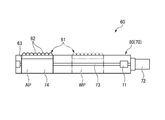
- FIG. 2 is a top view of the LED unit shown in FIG. 1 (b).
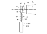
- FIG. 3 is a top view showing the vicinity of the LED unit whose moving mechanism is a cylinder device according to the first modification.
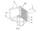
- FIG. 4A is a perspective view showing the vicinity of the LED unit in which the moving mechanism is configured by the rotating mechanism according to the second modification.
- FIG. 4B is a perspective view showing the vicinity of the LED unit in which the moving mechanism is configured by the rotating mechanism according to the third modification.
- FIG. 1A is a side view showing a schematic configuration of a lighting device for a proximity exposure device according to the present invention
- FIG. 1B is a top view thereof.
- FIG. 2 is a top view of the LED unit shown in FIG. 1 (b).
- FIG. 3 is a top view showing the vicinity of the LED unit whose
- FIG. 4C is a perspective view showing the vicinity of the LED unit in which the moving mechanism is composed of the rotating mechanism according to the fourth modification.
- FIG. 5A is a perspective view showing the vicinity of the LED unit in which the moving mechanism is composed of a plurality of ball screw mechanisms according to the fifth modification.
- FIG. 5B is a perspective view showing the vicinity of the LED unit in which the moving mechanism is composed of the ball screw mechanism and the rotating mechanism according to the sixth modification.
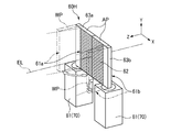
- FIG. 6A is a perspective view showing the vicinity of the LED unit in which the second light source unit is divided and the divided light source unit can move independently of each other by the ball screw mechanism according to the seventh modification.
- FIG. 5A is a perspective view showing the vicinity of the LED unit in which the moving mechanism is composed of a plurality of ball screw mechanisms according to the fifth modification.
- FIG. 5B is a perspective view showing the vicinity of the LED unit in which the moving mechanism is composed of the ball screw mechanism and the rotating mechanism according to the sixth modification.
- FIG. 6A is a perspective view
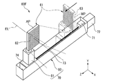
- FIG. 6B is a perspective view showing the vicinity of the LED unit in which the second light source unit is divided and the divided light source unit can move independently of each other by the rotation mechanism according to the eighth modification.
- FIG. 6C is a perspective view showing the vicinity of the LED unit in which the second light source unit is divided and the moving mechanism of each divided light source unit is composed of the ball screw mechanism and the rotation mechanism according to the ninth modification.
- the mask M held on the mask stage MS and the work W placed on the work stage WS are arranged via a predetermined gap and are close to each other.
- the light emitted from the lighting device for an exposure device (hereinafter, also simply referred to as a lighting device) 20 is applied to the work W via the mask M, and the pattern of the mask M is exposed and transferred to the work W.
- the lighting device 20 is a pair of cold mirrors 40, 41 that transmit the infrared rays of the light emitted from the first light source unit 30 and the first light source unit 30 that use the mercury lamp 31 as a light source and change the direction of the optical path EL.
- the exposure control shirter 45 which is arranged on the downstream side of the cold mirror 41 and controls the opening and closing of the light emitted from the first light source unit 30, and the light, which is arranged on the downstream side of the exposure control shirter 45, are used.
- At least one fly-eye lens 46 (three fly-eye lenses 46a, 46b, 46c in this embodiment) constituting an integrator for equalizing the intensity of light, and a field lens 49 for changing the traveling direction of light in the peripheral portion.
- a collimation mirror 50 that irradiates the light from the field lens 49 as parallel light, and a flat mirror 51 that irradiates the parallel light toward the mask M.
- the first light source unit 30 has, for example, a mercury lamp 31 and a plurality of reflectors (not shown) that collect the light emitted from the mercury lamp 31, and are arranged in a two-dimensional matrix.
- the light source may be composed of a single mercury lamp 31 and a reflector. Since the mercury lamp 31 also emits infrared rays, it is preferable to provide cold mirrors 40 and 41 that transmit infrared rays, and therefore a certain long optical path length is required.
- the fly-eye lens 46 is usually designed so that the illuminance on the exposed surface of the work W is the maximum illuminance in consideration of the tact time, and the illuminance on the incident surface of the fly-eye lens 46 is maximized. ..
- the three large, medium, and small fly-eye lenses 46a, 46b, and 46c can be slid and replaced, respectively, and the optimum size fly-eye lens 46 is selected according to the required exposure accuracy and the like. And used.
- the number of fly-eye lenses 46 is not limited to three.
- the field lens 49 is for efficiently using the light in the peripheral portion of the lens and is not always necessary, but it is desirable to provide the field lens 49 for improving the tact time.
- the lighting device 20 includes an LED unit 60 having a second light source unit 61 having a plurality of LED elements 62 as light sources, and a moving mechanism 70 for moving the second light source unit 61 in a direction intersecting the optical path EL. To be equipped with.
- the second light source unit 61 a plurality of (for example, about several hundred) LED elements (Light Emitting Diodes) 62 are arranged in a two-dimensional matrix and mounted on the base 63.
- the second light source unit 61 can be moved by the moving mechanism 70 between the operating position AP located on the optical path EL of the first light source unit 30 and the retracted position WP separated from the optical path EL.
- the operating position AP of the second light source unit 61 is set on the optical path EL of the first light source unit 30 and between the fly-eye lens 46 and the cold mirror 41 in the vicinity of the fly-eye lens 46.
- the operating position AP of the second light source unit 61 is arranged on the upstream side of the exposure control shirter 45, but since the LED element 62 has excellent output responsiveness, the exposure control shirter 45 controls the opening and closing of light. Does not need. Therefore, the operating position AP of the second light source unit 61 may be located on the downstream side of the exposure control shirter 45, on the upstream side of the fly-eye lens 46, and closer to the fly-eye lens 46. Further, unlike the mercury lamp 31, the LED element 62 does not emit infrared rays, and therefore can be arranged in the vicinity of the fly-eye lens 46. Therefore, at least the optical path EL on the downstream side of the exposure control shirter 45 is the same for the first light source unit 30 and the second light source unit 61.
- the size of the array of the mercury lamp 31 is larger than the size of the fly-eye lens 46, so that the light is condensed. Therefore, when the array of the LED element 62 is installed near the mercury lamp 31, the array of the LED element 62 needs to have the same size as the array of the mercury lamp 31, but when installed near the fly-eye lens 46, it becomes more. It becomes possible to make the size compact, and it is possible to prevent the size of the entire device from increasing.
- a screw shaft 73 rotationally driven by a motor 72 connected via a coupling 71 and a base 63 on which a second light source unit 61 is mounted are fixed and screwed. It is composed of a ball screw mechanism 80 including a nut 74 screwed into the shaft 73.
- the moving mechanism 70 is located at a position separated from the optical path EL so as not to block the light from the first light source unit 30 and the second light source unit 61 (the second in the embodiment shown in FIG. 1A). It is arranged below the light source unit 61).
- the second light source unit 61 is reciprocated between the operating position AP located on the optical path EL and the retracted position WP separated from the optical path EL, and the lighting device 20
- the light source is switched between the first light source unit 30 and the second light source unit 61, and the pattern of the mask M is exposed and transferred to the work W by the exposure light from one of the light source units 30 and 61.
- the exposure by the first light source unit 30 is first held by the mask stage Ms after the second light source unit 61 is positioned at the retracted position WP separated from the optical path EL by the moving mechanism 70.
- the mask M and the work W placed on the work stage Ws are adjusted to a gap of several tens to several hundreds of ⁇ m and arranged in close proximity to each other.
- the LED element 62 of the second light source unit 61 is turned off.
- the exposure light emitted from the first light source unit 30 using the mercury lamp 31 as a light source is reflected by the pair of cold mirrors 40 and 41, and the fly-eye lens is transmitted from the exposure control shirter 45 which is open-controlled. Condensing at 46.
- the exposure light emitted from the fly-eye lens 46 passes through the field lens 49, is reflected by the collimation mirror 50 to be parallel light having a predetermined collimation angle, and is incident on the mask M by the plane mirror 51.
- the exposure light transmitted through the mask M exposes the photoresist applied to the surface of the work W, and the mask pattern of the mask M is exposed and transferred to the work W.
- the motor 72 is rotated to bring the second light source unit 61 on the optical path EL. Positioned at the operating position AP. Then, the LED element 62 is turned on and the light is incident on the fly-eye lens 46. The exposure light emitted from the fly-eye lens 46 is similarly incident on the mask M via the field lens 49, the collimation mirror 50, and the plane mirror 51. Then, the exposure light transmitted through the mask M exposes the photoresist applied to the surface of the work W, and the mask pattern of the mask M is exposed and transferred to the work W.
- the second light source unit 61 is advanced or retracted onto the optical path EL of the first light source unit 30, and the light source is switched between the first light source unit 30 and the second light source unit 61 for use.
- both the mercury lamp and the LED can be used independently as the light source unit by one lighting device 20 for the proximity exposure device.
- the moving mechanism 70 is a cylinder device 75 instead of the ball screw mechanism of the above embodiment.
- the piston rod 76 of the cylinder device 75 is expanded and contracted, and the second light source unit 61 fixed to the tip of the piston rod 76 is separated from the operating position AP on the optical path EL and the retracted position from the optical path EL.
- (2nd to 4th modified examples) 4A to 4C show LED units 60B to 60D of the second to fourth modified examples in which the moving mechanism 70 is configured by the rotation mechanism. That is, the base 63 on which the second light source unit 61 is mounted is attached to the rotation shaft of the motor 81, which is a rotation mechanism. In each of the second to fourth modifications, the second light source unit 61 is rotated between the operating position AP of the first light source unit 30 on the optical path EL and the retracted position WP separated from the optical path EL. ..
- the second light source unit 61 in the case of exposure by the first light source unit 30, the second light source unit 61 is arranged at the retracted position WP separated from the optical path EL, and the first light source unit 61 is arranged. It does not block the light from 30. Further, in the case of exposure by the second light source unit 61, the second light source unit 61 lights a plurality of LED elements 62 at the operating position AP. As a result, by rotating the second light source unit 61 by the motor 81, the exposure in the first light source unit 30 and the second light source unit 61 can be arbitrarily switched. The position, rotation direction, and retract position WP of the rotation shaft of the motor 81 can be arbitrarily set.
- the moving mechanism 70 includes a first ball screw mechanism (first moving mechanism) 80A in which the second light source unit 61 is arranged on the nut 74.
- the first ball screw mechanism 80A is composed of a second ball screw mechanism (second moving mechanism) 80B arranged on another nut 74.
- the first ball screw mechanism 80A moves the second light source unit 61 in a direction (first direction) orthogonal to the optical path EL of the first light source unit 30, and the second ball screw mechanism 80B is a second ball screw mechanism 80B.
- the first ball screw mechanism 80A including the light source unit 61 of the above is moved in a direction parallel to the optical path EL (second direction).
- the moving mechanism 70 can move the second light source unit 61 between the operating position AP and the retracted position WP in an L-shaped locus in a top view.
- the moving mechanism 70 has a rotating mechanism (first moving mechanism) in which the second light source unit 61 is a motor 81 attached to the rotating shaft, and the motor 81. It is composed of a ball screw mechanism (second moving mechanism) 80 arranged on the nut 74.
- the motor 81 rotates and moves the second light source unit 61 from the posture orthogonal to the optical path EL of the first light source unit 30 to the rotation direction (first direction) in which the posture is along the optical path EL, and the ball screw mechanism 80. Moves the motor 81 including the second light source unit 61 in a direction (second direction) orthogonal to the optical path EL. As a result, the moving mechanism 70 can move the second light source unit 61 between the operating position AP and the retracted position WP.
- the moving mechanism 70 has a first moving mechanism that moves the second light source unit in the first direction, and a second light source unit that moves the second light source unit together with the first moving mechanism. It may be configured by a second moving mechanism that moves in a second direction different from the first direction.
- the first and second moving mechanisms may be a cylinder device as well as a ball screw mechanism and a rotating mechanism. Further, the first and second moving mechanisms may be driven at the same time, or may be individually driven sequentially. Further, the retracted position WP may be appropriately changed within a range that can be moved by the first moving mechanism and the second moving mechanism. Further, the moving mechanism 70 may be configured by combining three or more moving mechanisms. Such LED units 60E and 60F can increase the degree of freedom of the retracted position WP and can improve the maintenance workability.
- the second light source unit 61 is composed of a plurality of divided light source units 61a and 61b having a plurality of LED elements 62, respectively, and the LED units 60B of the seventh to ninth modified examples. It shows ⁇ 60D.
- the second light source unit 61 is composed of a pair of divided light source units 61a and 61b in which a plurality of LED elements 62 are arranged on the pair of substrates 63a and 63b, respectively.
- the moving mechanism 70 is provided for each of the divided light source units 61a and 61b, respectively.
- the substrates 63a and 63b are attached to the nuts 74 of the ball screw mechanism 80, respectively.
- the divided light source units 61a and 61b of the second light source unit 61 are located at the retracted position WP separated from the optical path EL, and are exposed by the second light source unit 61.
- the divided light source units 61a and 61b are located at the operating position AP on the optical path EL of the first light source unit 30.
- the pair of substrates 63a and 63b are in contact with each other or arranged in close proximity to each other.
- each moving mechanism 70 corresponding to the divided light source units 61a and 61b is configured by the motor 81, respectively.
- the pair of divided light source units 61a and 61b are rotationally driven on the optical path EL of the first light source unit 30 with the operating position AP in which the pair of substrates 63a and 63b are flush with each other, and are separated from the optical path EL.
- the pair of substrates 63a and 63b move to and from the retracted position WP in parallel.
- each moving mechanism 70 corresponding to the divided light source portions 61a and 61b is composed of a motor 81 and a ball screw mechanism 80, respectively.
- the divided light source units 61a and 61b of the second light source unit 61 are located at the retracted position WP separated from the optical path EL, and the second light source unit 61 At the time of exposure by, the divided light source units 61a and 61b are located at the operating position AP on the optical path EL.
- the weight of the divided light source units 61a and 61b can be reduced, and the movement of the divided light source units 61a and 61b can be speeded up. Further, a motor 72 having a small output can be used for the motor 72 of the ball screw mechanism 80.
- the number of divisions of the second light source unit 61 is not limited to the above, and may be three or more divisions, and a movement mechanism may be provided corresponding to each division light source unit. Further, the division of the second light source unit 61 is not limited to the left-right division of the seventh to ninth modifications, and may be a vertical division or an oblique division. In any of the modified examples, other configurations and effects are the same as those of the lighting device of the above embodiment.
- the present invention is not limited to the above-described embodiment, and can be appropriately modified, improved, and the like.
- the moving mechanism 70 moves the second light source unit 61 in the horizontal direction to switch between the operating position AP and the retracted position WP, but the second light source unit 61 is moved in the vertical direction. It may be moved to and switched between the operating position AP and the retracted position WP.
- the moving mechanism of the present invention is not limited to the ball screw mechanism, the cylinder device, and the rotating mechanism described above, and any mechanism for moving the LED unit between the operating position and the retracting position can be applied.
- An illuminating device that irradiates a work arranged through a mask and a predetermined gap with exposure light through the mask.
- the first light source unit that uses a mercury lamp as the light source, A fly-eye lens that uniformly emits light from the first light source unit, and A plurality of reflectors that reflect light from the first light source unit, and
- the second light source unit using a plurality of LED elements as light sources and the second light source unit are separated from the operating position located on the optical path of the first light source unit and the optical path of the first light source unit.
- An LED unit having a moving mechanism for moving between the retracted position and the retracted position, A lighting device for a proximity exposure device.
- one lighting device switches between the first light source unit and the second light source unit.
- the existing lighting device for a proximity exposure device using a mercury lamp as a light source can be easily modified by using an LED as a light source unit.
- the operating position of the second light source unit is set between the fly-eye lens and the reflector on the upstream side of the fly-eye lens and in the vicinity of the fly-eye lens.
- the lighting device for a proximity exposure device according to 1). According to this configuration, by setting the operating position of the second light source unit in the vicinity of the fly-eye lens, the light emitted from the plurality of LED elements can be effectively focused on the fly-eye lens.
- a second light source unit having a plurality of LED elements and an LED unit having a second light source unit can be compactly designed, and switching between the first light source unit and the second light source unit can be easily performed. it can.
- the moving mechanism is composed of at least one of a ball screw mechanism, a cylinder device, and a rotating mechanism.
- the second light source unit can be retracted to an appropriate retracted position according to the illumination device for the proximity exposure apparatus.
- the moving mechanism is different from the first direction together with the first moving mechanism for moving the second light source unit in the first direction and the second light source unit with the first moving mechanism.
- the lighting device for a proximity exposure device according to any one of (1) to (3), which is composed of a second moving mechanism that moves in two directions. According to this configuration, the second light source unit can be retracted to a more appropriate retracted position according to the illumination device for the proximity exposure apparatus.
- the second light source unit is composed of a plurality of divided light source units each having a plurality of LED elements.
- the lighting device for a proximity exposure device according to any one of (1) to (4), wherein the moving mechanism is provided for each of the plurality of divided light source units. According to this configuration, it is not necessary to provide a large retracted position at one place, and each moving mechanism can be designed compactly.
- the moving mechanism is an LED unit installed at a position separated from the optical path of the first light source unit. According to this configuration, the LED unit can be appropriately installed in the existing lighting device for a proximity exposure device using a mercury lamp as a light source.
- a proximity exposure apparatus comprising the illumination apparatus for a proximity exposure apparatus according to any one of (1) to (5), and exposing and transferring a mask pattern to a work by exposure light from the illumination apparatus. According to this configuration, the work can be efficiently exposed by switching between the first light source unit and the second light source unit.
- Proximity exposure device 20 Lighting device (Illumination device for proximity exposure device) 30 First light source unit 31 Mercury lamp 40, 41 Cold mirror (reflector) 46 Fly Eye Lens 50 Collimation Mirror (Reflector) 51 Planar mirror (reflector) 60 LED unit 61 Second light source unit 62 LED element 70 Moving mechanism 72 Motor (driving device) 73 Screw shaft 74 Nut AP Operating position EL Optical path M Mask W Work WP Retracting position
Landscapes
- Physics & Mathematics (AREA)
- General Physics & Mathematics (AREA)
- Engineering & Computer Science (AREA)
- Plasma & Fusion (AREA)
- Exposure And Positioning Against Photoresist Photosensitive Materials (AREA)
Abstract
光源部として、水銀ランプとLEDの両方を独立して使用可能な照明装置を提供する。水銀ランプ(31)を光源とする第1の光源部(30)と、該第1の光源部(30)からの光を均一にして出射するフライアイレンズ(46)と、第1の光源部(30)からの光をそれぞれ反射する複数の反射鏡(40,41,50,51)と、複数のLED素子(62)を光源とする第2の光源部(61)、及び該第2の光源部(61)を、第1の光源部(30)の光路EL上に位置する作動位置APと、第1の光源部(30)の光路ELから離間した退避位置WPとの間で移動させる移動機構(70)を有するLEDユニット(60)と、を備える。
Description
本発明は、マスクを介してワークに露光光を照射する照明装置、LEDユニット、近接露光装置及び近接露光装置の露光方法に関する。
従来、紫外線(特に、i線)を活用する露光装置としては、超高圧水銀ランプ等の放電型ランプを光源とし、該光源から照射された光によってステージに固定されたワークにマスクのパターンを露光転写するものが知られている。
また、特許文献1に記載の露光装置では、照明装置は、例えば、水銀ランプから構成された主光源と、該主光源とは出力応答特性が異なる、例えば、LEDから構成された補助光源と、主光源と補助光源の射出光を検出する光電センサと、被露光基板に照射される露光光の強度を変更する露光量制御部と、を備える。主光源は、目標最小照度から決定された照度で発光し、補助光源は、目標照度と主光源による照度との差分の照度を発光し、光合成部により主光源および補助光源から照射された光を合成して、装置の生産性を低下させることなく、光源の出力応答特性を向上させるようにした露光装置が開示されている。
また、特許文献2は、照明光学系が、水銀ランプ、LED、ハロゲンランプなどからなる、第1及び第2の光源部と、第1の光源部からの光を遮光可能なフィルタと、を有する。そして、基板とマスクとを所定のギャップに近接させた状態で、フィルタの開タイミングを制御することで第1及び第2の光源部からの光を異なるタイミングで基板に照射して、高解像度のパターンを形成するとともに、スループットを向上させた近接露光装置が開示されている。
ところで、水銀ランプ等の放電型ランプは、電源投入後に、出力が安定するまでに時間がかかり、出力変更時に短時間での出力可変が事実上難しい。また、フライアイレンズから離れた位置に光源を配置する場合、フライアイレンズの入射角を補う必要があるため、光源のサイズが大きくなる。さらに、放電型ランプは、消費電力が大きく、ランプ寿命が短いという問題があった。
一方、近年、近接露光装置用の照明装置としても、出力可変に対する応答性が略0.1msec以下である紫外線LEDなどを2次元でマトリクス状に配置した光源が使用され始めている。また、LEDは、水銀ランプと比較して消費電力が小さい利点も有する。このため、光源部を水銀ランプとした照明装置をすでに組み込んでいる既存の露光装置においても、LEDを光源部として使用できることが望まれている。特に、光源部を水銀ランプからLEDに切り替える際、実際にサンプルを通す条件合わせの試験が必要となるが、両光源を併用可能とすると、円滑に水銀ランプからLEDへの切り替えが可能となる。
特許文献1の露光装置は、LEDを補助光源として使用するものであり、また、特許文献2の露光装置も、LEDを一例として、第1の光源部を選択的に、第2の光源部に組み合わせて使用するものであり、上記課題を考慮したものでない。
本発明は、前述した課題に鑑みてなされたものであり、その目的は、光源部として、水銀ランプとLEDの両方を独立して使用可能な近接露光装置用照明装置、LEDユニット、近接露光装置及び近接露光装置の露光方法を提供することにある。
本発明の上記目的は、下記の構成により達成される。
(1) マスクと所定のギャップを介して配置されたワークに対し、該マスクを介して露光光を照射する照明装置であって、
水銀ランプを光源とする第1の光源部と、
該第1の光源部からの光を均一にして出射するフライアイレンズと、
前記第1の光源部からの光をそれぞれ反射する複数の反射鏡と、
複数のLED素子を光源とする第2の光源部、及び、該第2の光源部を、前記第1の光源部の光路上に位置する作動位置と、前記第1の光源部の光路から離間した退避位置との間で移動させる移動機構を有するLEDユニットと、
を備える、近接露光装置用照明装置。
(2) (1)に記載の近接露光装置用照明装置に使用されるLEDユニットであって、
前記移動機構は、前記第1の光源部の光路から離間した位置に設置される、LEDユニット。
(3) (1)に記載の近接露光装置用照明装置を備え、該照明装置からの露光光によりマスクのパターンをワークに露光転写する、近接露光装置。
(4) (3)に記載の近接露光装置を使用し、
前記照明装置からの露光光によりマスクのパターンをワークに露光転写する、近接露光装置の露光方法。
(1) マスクと所定のギャップを介して配置されたワークに対し、該マスクを介して露光光を照射する照明装置であって、
水銀ランプを光源とする第1の光源部と、
該第1の光源部からの光を均一にして出射するフライアイレンズと、
前記第1の光源部からの光をそれぞれ反射する複数の反射鏡と、
複数のLED素子を光源とする第2の光源部、及び、該第2の光源部を、前記第1の光源部の光路上に位置する作動位置と、前記第1の光源部の光路から離間した退避位置との間で移動させる移動機構を有するLEDユニットと、
を備える、近接露光装置用照明装置。
(2) (1)に記載の近接露光装置用照明装置に使用されるLEDユニットであって、
前記移動機構は、前記第1の光源部の光路から離間した位置に設置される、LEDユニット。
(3) (1)に記載の近接露光装置用照明装置を備え、該照明装置からの露光光によりマスクのパターンをワークに露光転写する、近接露光装置。
(4) (3)に記載の近接露光装置を使用し、
前記照明装置からの露光光によりマスクのパターンをワークに露光転写する、近接露光装置の露光方法。
本発明の近接露光装置用照明装置、LEDユニット、近接露光装置及び近接露光装置の露光方法によれば、1台の照明装置により、水銀ランプとLEDの両方を独立して使用することができる。
以下、本発明に係る近接露光装置用照明装置の一実施形態を図面に基づいて詳細に説明する。
図1に示すように、本実施形態の近接露光装置10は、マスクステージMSに保持されたマスクMと、ワークステージWSに載置されたワークWとを所定のギャップを介して配置し、近接露光装置用照明装置(以下では、単に照明装置とも言う)20から出射された光を、マスクMを介してワークWに照射して、マスクMのパターンをワークWに露光転写する。
図1に示すように、本実施形態の近接露光装置10は、マスクステージMSに保持されたマスクMと、ワークステージWSに載置されたワークWとを所定のギャップを介して配置し、近接露光装置用照明装置(以下では、単に照明装置とも言う)20から出射された光を、マスクMを介してワークWに照射して、マスクMのパターンをワークWに露光転写する。
照明装置20は、水銀ランプ31を光源とする第1の光源部30と、第1の光源部30から出射された光の赤外線を透過させ、光路ELの向きを変える一対のコールドミラー40,41と、コールドミラー41の下流側に配設されて第1の光源部30から出射された光を開閉制御する露光制御用シャツター45と、該露光制御用シャツター45の下流側に配置されて、光の強度を均一化するインテグレータを構成する少なくとも1枚のフライアイレンズ46(本実施形態では、3枚のフライアイレンズ46a,46b,46c)と、周辺部の光の進行方向を変えるフィールドレンズ49と、フィールドレンズ49からの光を平行光として照射するコリメーションミラー50と、該平行光をマスクMに向けて照射する平面ミラー51と、を備える。
第1の光源部30は、例えば水銀ランプ31と、この水銀ランプ31から出射された光を集光する不図示のリフレクタをそれぞれ複数有して、二次元でマトリックス配置される。なお、光源としては、単一の水銀ランプ31とリフレクタの構成であってもよい。水銀ランプ31は、赤外線も出射するので、赤外線を透過させるコールドミラー40,41を設けることが好ましく、そのためある程度の長い光路長が要求される。
フライアイレンズ46は、通常、ワークWの露光面における照度が、タクトタイムとの兼ね合いで最大の照度となるように、フライアイレンズ46の入射面での照度が最大となるように設計される。大、中、小の3枚のフライアイレンズ46a,46b,46cは、それぞれスライドさせて交換することを可能であり、要求される露光精度などに応じて最適なサイズのフライアイレンズ46が選択されて使用される。なお、フライアイレンズ46の枚数は3枚に限定されない。
フィールドレンズ49は、レンズ周辺部の光を効率的に使用するためのものであり、必ずしも必要としないが、タクトタイム向上のために設けることが望ましい。
また、照明装置20は、複数のLED素子62を光源とする第2の光源部61と、第2の光源部61を光路ELと交差する方向に移動させる移動機構70と、を有するLEDユニット60を備える。
図2も参照して、第2の光源部61は、複数(例えば、数百個程度)のLED素子(Light Emitting Diode)62が、二次元でマトリックス配置されて基体63に実装されている。第2の光源部61は、移動機構70により、第1の光源部30の光路EL上に位置する作動位置APと、該光路ELから離間した退避位置WPとの間で移動可能である。
第2の光源部61の作動位置APは、第1の光源部30の光路EL上、かつフライアイレンズ46とコールドミラー41との間で、フライアイレンズ46の近傍に設定されている。
なお、第2の光源部61の作動位置APは、露光制御用シャツター45の上流側に配置されているが、LED素子62は出力応答性に優れるため、露光制御用シャツター45による光の開閉制御を必要としない。従って、第2の光源部61の作動位置APは、露光制御用シャツター45の下流側とし、フライアイレンズ46よりも上流側で、フライアイレンズ46のより近傍に配置してもよい。
また、LED素子62は、水銀ランプ31と異なり、赤外線を出射しないので、フライアイレンズ46の近傍に配置することができる。従って、少なくとも露光制御用シャツター45より下流側の光路ELは、第1の光源部30と第2の光源部61とで同じものとなる。
また、LED素子62は、水銀ランプ31と異なり、赤外線を出射しないので、フライアイレンズ46の近傍に配置することができる。従って、少なくとも露光制御用シャツター45より下流側の光路ELは、第1の光源部30と第2の光源部61とで同じものとなる。
また、水銀ランプ31の光学系は、水銀ランプ31のアレイのサイズがフライアイレンズ46のサイズに比べて大きいため、集光させている。そのため、LED素子62のアレイを水銀ランプ31の近傍に設置すると、LED素子62のアレイも水銀ランプ31のアレイと同様のサイズにする必要があるが、フライアイレンズ46の近傍に設置すると、よりコンパクトなサイズにすることが可能になり、装置全体のサイズを大きくなるのを防ぐことができる。
図2に示すように、移動機構70は、カップリング71を介して連結されたモータ72により回転駆動されるねじ軸73と、第2の光源部61を実装する基体63が固定されて、ねじ軸73に螺合するナット74と、を備えるボールねじ機構80によって構成される。移動機構70は、第1の光源部30及び第2の光源部61からの光を阻害することがないように、光路ELから離間した位置(図1(a)に示す実施例では第2の光源部61の下方)に配設されている。
そして、モータ72を回転させることで、第2の光源部61を光路EL上に位置する作動位置APと、該光路ELから離間した退避位置WPとの間で往復移動させて、照明装置20の光源を、第1の光源部30と第2の光源部61に切り換え、いずれか一方の光源部30,61からの露光光によりマスクMのパターンをワークWに露光転写する。
第1の光源部30による露光は、図1に示すように、先ず、移動機構70により第2の光源部61を光路ELから離間した退避位置WPに位置させた後、マスクステージMsに保持されたマスクMと、ワークステージWsに載置されたワークWとを、数10~数100μmのギャップに調整して近接対向配置する。その際、第2の光源部61のLED素子62は、消灯している。
そして、水銀ランプ31を光源とする第1の光源部30から出射された露光用の光を、一対のコールドミラー40,41で反射し、開制御されている露光制御用シャツター45からフライアイレンズ46で集光させる。フライアイレンズ46から出射される露光用の光は、フィールドレンズ49を通って、コリメーションミラー50で反射されて所定のコリメーション角を持った平行光とされ、平面ミラー51によってマスクMに入射する。そして、マスクMを透過した露光用の光は、ワークWの表面に塗布されたフォトレジストを感光させてマスクMのマスクパターンがワークWに露光転写される。
一方、出力応答性に優れるLED素子62で構成された第2の光源部61による露光は、図2の実線で示すように、モータ72を回転させて第2の光源部61を光路EL上の作動位置APに位置させる。そして、LED素子62を点灯してその光をフライアイレンズ46に入射させる。フライアイレンズ46から出射される露光用の光は、同様に、フィールドレンズ49、コリメーションミラー50、及び平面ミラー51を介して、マスクMに入射する。そして、マスクMを透過した露光用の光は、ワークWの表面に塗布されたフォトレジストを感光させてマスクMのマスクパターンがワークWに露光転写される。
このように、第2の光源部61を、第1の光源部30の光路EL上に進出または退避させて、光源を第1の光源部30と第2の光源部61とに切り替えて使用することで、1台の近接露光装置用照明装置20により、水銀ランプとLEDの両方を光源部として独立して使用することが可能となる。
(第1変形例)
図3に示す第1変形例のLEDユニット60Aは、移動機構70を、上記実施形態のボールねじ機構の代わりに、シリンダ装置75としている。この場合、シリンダ装置75のピストンロッド76を伸縮して、該ピストンロッド76の先端に固定された第2の光源部61を、光路EL上の作動位置APと、該光路ELから離間した退避位置WPとの間で移動させる。
したがって、移動機構70がシリンダ装置75の場合も、光路ELから離間した位置に配設され、第1の光源部30及び第2の光源部61からの光を阻害することがない。
図3に示す第1変形例のLEDユニット60Aは、移動機構70を、上記実施形態のボールねじ機構の代わりに、シリンダ装置75としている。この場合、シリンダ装置75のピストンロッド76を伸縮して、該ピストンロッド76の先端に固定された第2の光源部61を、光路EL上の作動位置APと、該光路ELから離間した退避位置WPとの間で移動させる。
したがって、移動機構70がシリンダ装置75の場合も、光路ELから離間した位置に配設され、第1の光源部30及び第2の光源部61からの光を阻害することがない。
(第2~第4変形例)
図4A~図4Cは、移動機構70が回転機構によって構成される、第2~第4変形例のLEDユニット60B~60Dを示す。即ち、回転機構であるモータ81の回転軸に、第2の光源部61を実装する基体63が取り付けられる。第2~第4変形例のいずれも、第2の光源部61を、第1の光源部30の光路EL上の作動位置APと、該光路ELから離間した退避位置WPとの間で回転させる。
図4A~図4Cは、移動機構70が回転機構によって構成される、第2~第4変形例のLEDユニット60B~60Dを示す。即ち、回転機構であるモータ81の回転軸に、第2の光源部61を実装する基体63が取り付けられる。第2~第4変形例のいずれも、第2の光源部61を、第1の光源部30の光路EL上の作動位置APと、該光路ELから離間した退避位置WPとの間で回転させる。
したがって、第2~第4変形例では、第1の光源部30による露光の場合には、第2の光源部61は、光路ELから離間した退避位置WPに配設され、第1の光源部30からの光を阻害することがない。また、第2の光源部61による露光の場合には、第2の光源部61は、作動位置APにて複数のLED素子62を点灯する。
この結果、モータ81によって第2の光源部61を回転させることで、第1の光源部30と第2の光源部61での露光を任意に切り替え可能となる。
なお、モータ81の回転軸の位置や回転方向、退避位置WPは任意に設定可能である。
この結果、モータ81によって第2の光源部61を回転させることで、第1の光源部30と第2の光源部61での露光を任意に切り替え可能となる。
なお、モータ81の回転軸の位置や回転方向、退避位置WPは任意に設定可能である。
(第5~第6変形例)
また、図5Aに示す第5変形例のLEDユニット60Eでは、移動機構70は、第2の光源部61がナット74に配置された第1のボールねじ機構(第1の移動機構)80Aと、該第1のボールねじ機構80Aが他のナット74に配置された第2のボールねじ機構(第2の移動機構)80Bと、によって構成される。
また、図5Aに示す第5変形例のLEDユニット60Eでは、移動機構70は、第2の光源部61がナット74に配置された第1のボールねじ機構(第1の移動機構)80Aと、該第1のボールねじ機構80Aが他のナット74に配置された第2のボールねじ機構(第2の移動機構)80Bと、によって構成される。
第1のボールねじ機構80Aは、第2の光源部61を第1の光源部30の光路ELに直交する方向(第1の方向)に移動させ、第2のボールねじ機構80Bは、第2の光源部61を含む、第1のボールねじ機構80Aを光路ELと平行な方向(第2の方向)に移動させる。これにより、移動機構70は、第2の光源部61を、作動位置APと退避位置WPとの間で、上面視で、L字型の軌跡で移動させることができる。
図5Bに示す第6変形例のLEDユニット60Fは、移動機構70を、第2の光源部61が回転軸に取付けられたモータ81である回転機構(第1の移動機構)と、モータ81がナット74に配置されたボールねじ機構(第2の移動機構)80とによって構成する。
モータ81は、第2の光源部61を第1の光源部30の光路ELに直交する姿勢から光路ELに沿った姿勢となる回転方向(第1の方向)に回転移動させ、ボールねじ機構80は、第2の光源部61を含むモータ81を光路ELと直交する方向(第2の方向)に移動させる。これにより、移動機構70は、第2の光源部61を、作動位置APと退避位置WPとの間で移動させることができる。
これら第5及び第6変形例のように、移動機構70は、第2の光源部を第1の方向に移動させる第1の移動機構と、第2の光源部を第1の移動機構と共に第1の方向と異なる第2の方向に移動させる第2の移動機構とによって構成してもよい。第1及び第2の移動機構は、ボールねじ機構、回転機構の他、シリンダ装置であってもよい。また、第1及び第2の移動機構は、同時に駆動させてもよいし、個々に順次駆動させてもよい。さらに、退避位置WPは、第1の移動機構と第2の移動機構とによって移動可能な範囲において、適宜変更してもよい。また、移動機構70は、3つ以上の移動機構を組み合わせて構成されてもよい。
このようなLEDユニット60E,60Fは、退避位置WPの自由度を上げることができ、また、メンテナンス作業性を向上することができる。
このようなLEDユニット60E,60Fは、退避位置WPの自由度を上げることができ、また、メンテナンス作業性を向上することができる。
(第7~第9変形例)
次に、図6A~図6Cは、第2の光源部61が、複数のLED素子62をそれぞれ有する複数の分割光源部61a,61bによって構成される、第7~第9変形例のLEDユニット60B~60Dを示す。
例えば、図6Aでは、第2の光源部61は、一対の基体63a,63bに複数のLED素子62がそれぞれ配置された一対の分割光源部61a,61bによって構成される。移動機構70は、分割光源部61a,61bごとにそれぞれ設けられる。この場合、各基体63a、63bが、各ボールねじ機構80のナット74にそれぞれ取り付けられる。
次に、図6A~図6Cは、第2の光源部61が、複数のLED素子62をそれぞれ有する複数の分割光源部61a,61bによって構成される、第7~第9変形例のLEDユニット60B~60Dを示す。
例えば、図6Aでは、第2の光源部61は、一対の基体63a,63bに複数のLED素子62がそれぞれ配置された一対の分割光源部61a,61bによって構成される。移動機構70は、分割光源部61a,61bごとにそれぞれ設けられる。この場合、各基体63a、63bが、各ボールねじ機構80のナット74にそれぞれ取り付けられる。
そして、第1の光源部30による露光の場合には、第2の光源部61の分割光源部61a、61bは、光路ELから離間した退避位置WPに位置し、第2の光源部61による露光の際には、分割光源部61a、61bは、第1の光源部30の光路EL上の作動位置APに位置する。このとき、一対の基体63a,63bは、互いに当接されるか、または近接して配置される。
また、図6Bでは、分割光源部61a、61bに対応する各移動機構70は、モータ81によってそれぞれ構成される。一対の分割光源部61a、61bは、第1の光源部30の光路EL上で、一対の基体63a、63bが互いに面一となる作動位置APと、回転駆動されて、該光路ELから離間し、一対の基体63a、63bが平行となる退避位置WPとの間で移動する。
さらに、図6Cでは、分割光源部61a、61bに対応する各移動機構70は、モータ81とボールねじ機構80とによってそれぞれ構成される。この場合も、第1の光源部30による露光の場合には、第2の光源部61の分割光源部61a、61bは、光路ELから離間した退避位置WPに位置し、第2の光源部61による露光の際には、分割光源部61a、61bは、光路EL上の作動位置APに位置する。
第7~第9変形例のように、第2の光源部61を分割することによって、各分割光源部61a、61bの重量を小さくでき、各分割光源部61a、61bの移動を高速化でき、また、ボールねじ機構80のモータ72に出力が小さなものを利用できる。
なお、第2の光源部61の分割数は、上記に限らず、3分割以上であってもよく、各分割光源部に対応して移動機構をそれぞれ設ければよい。また、第2の光源部61の分割は、第7~第9変形例の左右分割に限らず、上下分割であってもよいし、斜めに分割してもよい。
いずれの変形例においても、その他の構成及び効果は、上記実施形態の照明装置と同様である。
いずれの変形例においても、その他の構成及び効果は、上記実施形態の照明装置と同様である。
尚、本発明は、前述した一実施形態に限定されるものではなく、適宜、変形、改良、等が可能である。
例えば、本実施形態では、移動機構70によって、第2の光源部61を水平方向に移動させて作動位置APと退避位置WPとの間で切り替えているが、第2の光源部61を上下方向に移動させて作動位置APと退避位置WPとの間で切り替えてもよい。
また、本発明の移動機構は、上述したボールねじ機構やシリンダ装置、回転機構に限定されず、LEDユニットを作動位置と退避位置との間で移動させる任意の機構が適用できる。
例えば、本実施形態では、移動機構70によって、第2の光源部61を水平方向に移動させて作動位置APと退避位置WPとの間で切り替えているが、第2の光源部61を上下方向に移動させて作動位置APと退避位置WPとの間で切り替えてもよい。
また、本発明の移動機構は、上述したボールねじ機構やシリンダ装置、回転機構に限定されず、LEDユニットを作動位置と退避位置との間で移動させる任意の機構が適用できる。
以上の通り、本明細書には次の事項が開示されている。
(1) マスクと所定のギャップを介して配置されたワークに対し、該マスクを介して露光光を照射する照明装置であって、
水銀ランプを光源とする第1の光源部と、
該第1の光源部からの光を均一にして出射するフライアイレンズと、
前記第1の光源部からの光をそれぞれ反射する複数の反射鏡と、
複数のLED素子を光源とする第2の光源部、及び、該第2の光源部を、前記第1の光源部の光路上に位置する作動位置と、前記第1の光源部の光路から離間した退避位置との間で移動させる移動機構を有するLEDユニットと、
を備える、近接露光装置用照明装置。
この構成によれば、第2の光源部を第1の光源部の光路上に進出または退避させることで、1台の照明装置により、第1の光源部と第2の光源部とを切り替えて使用することができる。また、水銀ランプを光源とする既存の近接露光装置用照明装置に、LEDを光源部として容易に改修することができる。
(1) マスクと所定のギャップを介して配置されたワークに対し、該マスクを介して露光光を照射する照明装置であって、
水銀ランプを光源とする第1の光源部と、
該第1の光源部からの光を均一にして出射するフライアイレンズと、
前記第1の光源部からの光をそれぞれ反射する複数の反射鏡と、
複数のLED素子を光源とする第2の光源部、及び、該第2の光源部を、前記第1の光源部の光路上に位置する作動位置と、前記第1の光源部の光路から離間した退避位置との間で移動させる移動機構を有するLEDユニットと、
を備える、近接露光装置用照明装置。
この構成によれば、第2の光源部を第1の光源部の光路上に進出または退避させることで、1台の照明装置により、第1の光源部と第2の光源部とを切り替えて使用することができる。また、水銀ランプを光源とする既存の近接露光装置用照明装置に、LEDを光源部として容易に改修することができる。
(2) 前記第2の光源部の作動位置は、前記フライアイレンズと、該フライアイレンズよりも上流側の前記反射鏡との間で、かつ前記フライアイレンズの近傍に設定される、(1)に記載の近接露光装置用照明装置。
この構成によれば、第2の光源部の作動位置をフライアイレンズの近傍とすることで、複数のLED素子から出射される光を効果的にフライアイレンズに集光することができるので、複数のLED素子を有する第2の光源部、及び第2の光源部を有するLEDユニットをコンパクトに設計でき、また、第1の光源部と第2の光源部との切り替えも容易に行うことができる。
この構成によれば、第2の光源部の作動位置をフライアイレンズの近傍とすることで、複数のLED素子から出射される光を効果的にフライアイレンズに集光することができるので、複数のLED素子を有する第2の光源部、及び第2の光源部を有するLEDユニットをコンパクトに設計でき、また、第1の光源部と第2の光源部との切り替えも容易に行うことができる。
(3) 前記移動機構は、ボールねじ機構、シリンダ装置、回転機構の少なくとも一つによって構成される、(1)又は(2)に記載の近接露光装置用照明装置。
この構成によれば、第2の光源部を、近接露光装置用照明装置に応じて、適切な退避位置に退避させることができる。
この構成によれば、第2の光源部を、近接露光装置用照明装置に応じて、適切な退避位置に退避させることができる。
(4) 前記移動機構は、前記第2の光源部を第1の方向に移動させる第1の移動機構と、前記第2の光源部を前記第1の移動機構と共に第1の方向と異なる第2の方向に移動させる第2の移動機構とによって構成される、(1)~(3)のいずれかに記載の近接露光装置用照明装置。
この構成によれば、第2の光源部を、近接露光装置用照明装置に応じて、より適切な退避位置に退避させることができる。
この構成によれば、第2の光源部を、近接露光装置用照明装置に応じて、より適切な退避位置に退避させることができる。
(5) 前記第2の光源部は、複数のLED素子をそれぞれ有する複数の分割光源部によって構成され、
前記移動機構は、前記複数の分割光源部ごとに設けられる、(1)~(4)のいずれかに記載の近接露光装置用照明装置。
この構成によれば、1か所に大きな退避位置を設ける必要がなくなり、また、各移動機構をコンパクトに設計できる。
前記移動機構は、前記複数の分割光源部ごとに設けられる、(1)~(4)のいずれかに記載の近接露光装置用照明装置。
この構成によれば、1か所に大きな退避位置を設ける必要がなくなり、また、各移動機構をコンパクトに設計できる。
(6) (1)~(5)のいずれかに記載の近接露光装置用照明装置に使用されるLEDユニットであって、
前記移動機構は、前記第1の光源部の光路から離間した位置に設置される、LEDユニット。
この構成によれば、水銀ランプを光源とする既存の近接露光装置用照明装置に、LEDユニットを適切に設置することができる。
前記移動機構は、前記第1の光源部の光路から離間した位置に設置される、LEDユニット。
この構成によれば、水銀ランプを光源とする既存の近接露光装置用照明装置に、LEDユニットを適切に設置することができる。
(7) (1)~(5)のいずれかに記載の近接露光装置用照明装置を備え、該照明装置からの露光光によりマスクのパターンをワークに露光転写する、近接露光装置。
この構成によれば、第1の光源部と第2の光源部とを切り替えて、ワークを効率的に露光することができる。
この構成によれば、第1の光源部と第2の光源部とを切り替えて、ワークを効率的に露光することができる。
(8) (7)に記載の近接露光装置を使用し、
前記照明装置からの露光光によりマスクのパターンをワークに露光転写する、近接露光装置の露光方法。
この構成によれば、第1の光源部と第2の光源部とを切り替えて、ワークを効率的に露光することができる。
前記照明装置からの露光光によりマスクのパターンをワークに露光転写する、近接露光装置の露光方法。
この構成によれば、第1の光源部と第2の光源部とを切り替えて、ワークを効率的に露光することができる。
なお、本出願は、2019年10月11日出願の日本特許出願(特願2019-187715)に基づくものであり、その内容は本出願の中に参照として援用される。
10 近接露光装置
20 照明装置(近接露光装置用照明装置)
30 第1の光源部
31 水銀ランプ
40,41 コールドミラー(反射鏡)
46 フライアイレンズ
50 コリメーションミラー(反射鏡)
51 平面ミラー(反射鏡)
60 LEDユニット
61 第2の光源部
62 LED素子
70 移動機構
72 モータ(駆動装置)
73 ねじ軸
74 ナット
AP 作動位置
EL 光路
M マスク
W ワーク
WP 退避位置
20 照明装置(近接露光装置用照明装置)
30 第1の光源部
31 水銀ランプ
40,41 コールドミラー(反射鏡)
46 フライアイレンズ
50 コリメーションミラー(反射鏡)
51 平面ミラー(反射鏡)
60 LEDユニット
61 第2の光源部
62 LED素子
70 移動機構
72 モータ(駆動装置)
73 ねじ軸
74 ナット
AP 作動位置
EL 光路
M マスク
W ワーク
WP 退避位置
Claims (8)
- マスクと所定のギャップを介して配置されたワークに対し、該マスクを介して露光光を照射する照明装置であって、
水銀ランプを光源とする第1の光源部と、
該第1の光源部からの光を均一にして出射するフライアイレンズと、
前記第1の光源部からの光をそれぞれ反射する複数の反射鏡と、
複数のLED素子を光源とする第2の光源部、及び、該第2の光源部を、前記第1の光源部の光路上に位置する作動位置と、前記第1の光源部の光路から離間した退避位置との間で移動させる移動機構を有するLEDユニットと、
を備える、近接露光装置用照明装置。 - 前記第2の光源部の作動位置は、前記フライアイレンズと、該フライアイレンズよりも上流側の前記反射鏡との間で、かつ前記フライアイレンズの近傍に設定される、請求項1に記載の近接露光装置用照明装置。
- 前記移動機構は、ボールねじ機構、シリンダ装置、回転機構の少なくとも一つによって構成される、請求項1又は2に記載の近接露光装置用照明装置。
- 前記移動機構は、前記第2の光源部を第1の方向に移動させる第1の移動機構と、前記第2の光源部を前記第1の移動機構と共に第1の方向と異なる第2の方向に移動させる第2の移動機構とによって構成される、請求項1~3のいずれか1項に記載の近接露光装置用照明装置。
- 前記第2の光源部は、複数のLED素子をそれぞれ有する複数の分割光源部によって構成され、
前記移動機構は、前記複数の分割光源部ごとに設けられる、請求項1~4のいずれか1項に記載の近接露光装置用照明装置。 - 請求項1~5のいずれか1項に記載の近接露光装置用照明装置に使用されるLEDユニットであって、
前記移動機構は、前記第1の光源部の光路から離間した位置に設置される、LEDユニット。 - 請求項1~5のいずれか1項に記載の近接露光装置用照明装置を備え、該照明装置からの露光光によりマスクのパターンをワークに露光転写する、近接露光装置。
- 請求項7に記載の近接露光装置を使用し、
前記照明装置からの露光光によりマスクのパターンをワークに露光転写する、近接露光装置の露光方法。
Priority Applications (3)
| Application Number | Priority Date | Filing Date | Title |
|---|---|---|---|
| CN202080071438.2A CN114556221A (zh) | 2019-10-11 | 2020-09-25 | 接近式曝光装置用照明装置、led单元、接近式曝光装置及接近式曝光装置的曝光方法 |
| KR1020227011198A KR102910120B1 (ko) | 2019-10-11 | 2020-09-25 | 근접 노광 장치용 조명 장치, led 유닛, 근접 노광 장치 및 근접 노광 장치의 노광 방법 |
| JP2021551204A JP7548589B2 (ja) | 2019-10-11 | 2020-09-25 | 近接露光装置用照明装置、近接露光装置及び近接露光装置の露光方法 |
Applications Claiming Priority (2)
| Application Number | Priority Date | Filing Date | Title |
|---|---|---|---|
| JP2019-187715 | 2019-10-11 | ||
| JP2019187715 | 2019-10-11 |
Publications (1)
| Publication Number | Publication Date |
|---|---|
| WO2021070643A1 true WO2021070643A1 (ja) | 2021-04-15 |
Family
ID=75437238
Family Applications (1)
| Application Number | Title | Priority Date | Filing Date |
|---|---|---|---|
| PCT/JP2020/036432 Ceased WO2021070643A1 (ja) | 2019-10-11 | 2020-09-25 | 近接露光装置用照明装置、ledユニット、近接露光装置及び近接露光装置の露光方法 |
Country Status (5)
| Country | Link |
|---|---|
| JP (1) | JP7548589B2 (ja) |
| KR (1) | KR102910120B1 (ja) |
| CN (1) | CN114556221A (ja) |
| TW (1) | TWI872128B (ja) |
| WO (1) | WO2021070643A1 (ja) |
Cited By (2)
| Publication number | Priority date | Publication date | Assignee | Title |
|---|---|---|---|---|
| JP7141167B1 (ja) * | 2021-04-16 | 2022-09-22 | フェニックス電機株式会社 | 光照射装置、露光装置、および露光方法 |
| WO2022220229A1 (ja) * | 2021-04-16 | 2022-10-20 | フェニックス電機株式会社 | 露光用光源、光照射装置、露光装置、および露光方法 |
Citations (5)
| Publication number | Priority date | Publication date | Assignee | Title |
|---|---|---|---|---|
| JP2006110228A (ja) * | 2004-10-18 | 2006-04-27 | Pentax Corp | 内視鏡用光源装置 |
| JP2009098043A (ja) * | 2007-10-18 | 2009-05-07 | Nippon Soda Co Ltd | 試料測定装置及び試料測定方法 |
| JP2010118383A (ja) * | 2008-11-11 | 2010-05-27 | Nikon Corp | 照明装置、露光装置、及びデバイス製造方法 |
| JP2011203555A (ja) * | 2010-03-26 | 2011-10-13 | Dainippon Screen Mfg Co Ltd | 画像記録装置および画像記録方法 |
| WO2012067246A1 (ja) * | 2010-11-19 | 2012-05-24 | Nskテクノロジー株式会社 | 近接露光装置及び近接露光方法 |
Family Cites Families (9)
| Publication number | Priority date | Publication date | Assignee | Title |
|---|---|---|---|---|
| DE3210803A1 (de) * | 1982-03-24 | 1983-10-20 | Rainer 6078 Neu-Isenburg Kleber | Metallhalogenid-belichtungseinrichtung mit doppel- oder mehrfachspektraler lampenanordnung zum belichten von druckplatten, reproduktionsfilmen und anderen lichtempfindlichen schichten unterschiedlicher spektralempfindlichkeit |
| JPH04104255A (ja) * | 1990-08-24 | 1992-04-06 | Hitachi Ltd | 縮小投影露光装置 |
| JPH11231221A (ja) * | 1998-02-10 | 1999-08-27 | Nikon Corp | 照明装置と露光装置及び半導体デバイスの製造方法 |
| KR20090107982A (ko) * | 2008-04-10 | 2009-10-14 | 캐논 가부시끼가이샤 | 노광 장치 및 디바이스 제조 방법 |
| JP5875335B2 (ja) * | 2011-11-15 | 2016-03-02 | キヤノン株式会社 | 位置検出装置および露光装置 |
| JP2013205613A (ja) | 2012-03-28 | 2013-10-07 | Nsk Technology Co Ltd | 近接露光装置 |
| JP2015087517A (ja) | 2013-10-30 | 2015-05-07 | キヤノン株式会社 | 露光装置 |
| DE202016103819U1 (de) * | 2016-07-14 | 2017-10-20 | Suss Microtec Lithography Gmbh | Lichtquellenanordnung für ein Belichtungssystem sowie Fotolithografie-Belichtungssystem |
| JPWO2019155886A1 (ja) * | 2018-02-08 | 2021-01-28 | 株式会社ブイ・テクノロジー | 近接露光装置、近接露光方法、及び近接露光装置用光照射装置 |
-
2020
- 2020-09-25 KR KR1020227011198A patent/KR102910120B1/ko active Active
- 2020-09-25 WO PCT/JP2020/036432 patent/WO2021070643A1/ja not_active Ceased
- 2020-09-25 CN CN202080071438.2A patent/CN114556221A/zh active Pending
- 2020-09-25 JP JP2021551204A patent/JP7548589B2/ja active Active
- 2020-10-07 TW TW109134723A patent/TWI872128B/zh active
Patent Citations (5)
| Publication number | Priority date | Publication date | Assignee | Title |
|---|---|---|---|---|
| JP2006110228A (ja) * | 2004-10-18 | 2006-04-27 | Pentax Corp | 内視鏡用光源装置 |
| JP2009098043A (ja) * | 2007-10-18 | 2009-05-07 | Nippon Soda Co Ltd | 試料測定装置及び試料測定方法 |
| JP2010118383A (ja) * | 2008-11-11 | 2010-05-27 | Nikon Corp | 照明装置、露光装置、及びデバイス製造方法 |
| JP2011203555A (ja) * | 2010-03-26 | 2011-10-13 | Dainippon Screen Mfg Co Ltd | 画像記録装置および画像記録方法 |
| WO2012067246A1 (ja) * | 2010-11-19 | 2012-05-24 | Nskテクノロジー株式会社 | 近接露光装置及び近接露光方法 |
Cited By (3)
| Publication number | Priority date | Publication date | Assignee | Title |
|---|---|---|---|---|
| JP7141167B1 (ja) * | 2021-04-16 | 2022-09-22 | フェニックス電機株式会社 | 光照射装置、露光装置、および露光方法 |
| WO2022220229A1 (ja) * | 2021-04-16 | 2022-10-20 | フェニックス電機株式会社 | 露光用光源、光照射装置、露光装置、および露光方法 |
| CN117157589A (zh) * | 2021-04-16 | 2023-12-01 | 凤凰电机公司 | 曝光用光源、光照射装置、曝光装置、以及曝光方法 |
Also Published As
| Publication number | Publication date |
|---|---|
| KR20220079549A (ko) | 2022-06-13 |
| KR102910120B1 (ko) | 2026-01-08 |
| CN114556221A (zh) | 2022-05-27 |
| TWI872128B (zh) | 2025-02-11 |
| JP7548589B2 (ja) | 2024-09-10 |
| TW202134795A (zh) | 2021-09-16 |
| JPWO2021070643A1 (ja) | 2021-04-15 |
Similar Documents
| Publication | Publication Date | Title |
|---|---|---|
| JP5543516B2 (ja) | Euvリソグラフィ用照明システム及びこの種の照明システムに使用する第1及び第2の光学要素 | |
| US20220010940A1 (en) | Vehicle headlight having a light source | |
| EP2719942B1 (en) | Optical unit | |
| JP3316937B2 (ja) | 照明光学装置、露光装置、及び該露光装置を用いた転写方法 | |
| US20050174650A1 (en) | Lighting system, particularly for use in extreme ultraviolet (euv) lithography | |
| TW200602680A (en) | Variable focal length lens comprising micromirrors with one degree of freedom rotation and one degree of freedom translation | |
| WO2020010936A1 (zh) | 一种基于pbs分光器的自适应远光功能调节方法及其智能车灯模组 | |
| JP7548589B2 (ja) | 近接露光装置用照明装置、近接露光装置及び近接露光装置の露光方法 | |
| CN113805439A (zh) | 一种投影光刻机、照明系统、控制系统及方法 | |
| CN106796346B (zh) | 借助于光学装置处理光 | |
| CN104395669A (zh) | 用于自动照明器的改进的漫射系统 | |
| WO2010099370A1 (en) | Solid-state array for lithography illumination | |
| US20090122546A1 (en) | Movable Lighting System Providing Adjustable Illumination Zone | |
| TWI537599B (zh) | Light emitting diode light source device and exposure device | |
| CN1766737A (zh) | 光刻设备及器件制造方法 | |
| JP2022174212A (ja) | デジタルマイクロミラーデバイス及びスタティックリフレクタを用いたヘッドランプ | |
| CN109838748A (zh) | 一种自适应远光功能调节方法及其车灯 | |
| CN114729738B (zh) | 照明装置 | |
| TW200918223A (en) | Laser processing device and laser processing method | |
| JP2018206668A (ja) | 照明装置 | |
| KR20050062164A (ko) | 디스플레이장치의 노광구조 | |
| JP3237015U (ja) | 多光源共通光路型の照明システム | |
| JP2007206143A (ja) | 投写型表示装置 | |
| EP3816504B1 (en) | System and method for producing a blending light distribution from led luminaires | |
| JP2007292999A (ja) | 露光装置の光源 |
Legal Events
| Date | Code | Title | Description |
|---|---|---|---|
| 121 | Ep: the epo has been informed by wipo that ep was designated in this application |
Ref document number: 20873543 Country of ref document: EP Kind code of ref document: A1 |
|
| ENP | Entry into the national phase |
Ref document number: 2021551204 Country of ref document: JP Kind code of ref document: A |
|
| NENP | Non-entry into the national phase |
Ref country code: DE |
|
| 122 | Ep: pct application non-entry in european phase |
Ref document number: 20873543 Country of ref document: EP Kind code of ref document: A1 |