WO2021070345A1 - 金属製エレメント及びスライドファスナー - Google Patents
金属製エレメント及びスライドファスナー Download PDFInfo
- Publication number
- WO2021070345A1 WO2021070345A1 PCT/JP2019/040109 JP2019040109W WO2021070345A1 WO 2021070345 A1 WO2021070345 A1 WO 2021070345A1 JP 2019040109 W JP2019040109 W JP 2019040109W WO 2021070345 A1 WO2021070345 A1 WO 2021070345A1
- Authority
- WO
- WIPO (PCT)
- Prior art keywords
- metal element
- legs
- restraining
- plane
- core
- Prior art date
Links
Images


Classifications
-
- A—HUMAN NECESSITIES
- A44—HABERDASHERY; JEWELLERY
- A44B—BUTTONS, PINS, BUCKLES, SLIDE FASTENERS, OR THE LIKE
- A44B19/00—Slide fasteners
- A44B19/02—Slide fasteners with a series of separate interlocking members secured to each stringer tape
- A44B19/04—Stringers arranged edge-to-edge when fastened, e.g. abutting stringers
- A44B19/06—Stringers arranged edge-to-edge when fastened, e.g. abutting stringers with substantially rectangular members having interlocking projections and pieces
-
- A—HUMAN NECESSITIES
- A44—HABERDASHERY; JEWELLERY
- A44B—BUTTONS, PINS, BUCKLES, SLIDE FASTENERS, OR THE LIKE
- A44B19/00—Slide fasteners
- A44B19/24—Details
- A44B19/40—Connection of separate, or one-piece, interlocking members to stringer tapes; Reinforcing such connections, e.g. by stitching
- A44B19/403—Connection of separate interlocking members
Definitions
- This disclosure relates to metal elements and slide fasteners.
- Patent Document 1 relates to a metal wire rod, in short, a method for manufacturing a fastener element of a type in which a fastener element is cut out from a Y bar.
- Patent Document 2 relates to a method for manufacturing a fastener element of a type in which a fastener element is obtained from a metal flat plate by punching (see FIG. 6 of the same document).
- Patent Document 3 relates to a method for manufacturing a fastener element of a type in which a fastener element is obtained from a metal flat plate by punching.
- a hook-shaped tape holding portion is provided on the leg portion to increase the adhesive force to the fastener tape (see FIG. 1 of the same document).
- the method for manufacturing a fastener element of the type in which the fastener element is cut out from the Y bar as disclosed in Patent Document 1 is of the type disclosed in Patent Documents 2 and 3 in some respects such as reduction of material cost. It is more advantageous than the manufacturing method of the fastener element.
- the weight of the slide fastener can be reduced by adopting a lightweight metal material.
- the unit price of the metal element can be reduced and the price competitiveness of the slide fastener can be enhanced.
- the hardness of a metal element depends more or less on the metal material. Therefore, depending on the metal material used, the main characteristics of the slide fastener, in short, the lateral pulling strength may not be obtained.
- the inventor of the present application has found the significance of increasing the lateral pulling strength of the slide fastener by a new structure of the metal element.
- the present invention is not limited to the metal element made of a new metal material, but is also effective and useful for a metal element made of an existing metal material.
- the metal element according to one aspect of the present disclosure is a metal element attached to the core cord of the fastener tape.
- the metal element includes a pair of legs that sandwich the core cord and a head that connects the pair of legs.
- Each leg is a cantilever extending from a base end connected to the head to a free end.
- the free end of each leg is provided with a restraining claw having a restraining surface for restraining the core cord that moves away from the pair of legs.
- the restraining surfaces of the pair of legs gradually incline so as to approach each other as they move away from the head.
- the head is shaped like a cup so as to have an engaging protrusion and an engaging recess on the same axis.
- the engaging protrusion protrudes from the first side surface of the metal element formed flat in a range extending over the head and the legs.
- the engaging recess is recessed from the second side surface of the metal element formed flat in a range extending over the head and the legs.
- the second side surface is provided on the opposite side of the first side surface.
- the pair of legs are provided with a core cord compression surface that gradually inclines so as to approach each other as the distance from the restraining surface increases.
- Each core string compression surface extends from the restraining surface until it reaches the base end of the leg.
- the thickness of the leg portion in the thickness direction of the fastener tape gradually increases from the free end portion to the base end portion of the leg portion at least according to the inclination of the core string compression surface.
- the angle between the plane oriented parallel to the plane on which the fastener tape is present and the restraining surface is 60 ° or less, and / or the plane on which the fastener tape is present.
- the angle formed by the plane oriented parallel to the core string compression surface is 6 ° or more and 30 ° or less.
- the angle formed by the plane oriented parallel to the plane on which the fastener tape is present and the restraining surface is ⁇ , and the angle is oriented parallel to the plane on which the fastener tape is present.
- the angle between the restraining surface and the core string compression surface is in the range of 100 ° to 135 °.
- a virtual line is provided to connect the boundary between the top surface of the restraint claw and the restraint surface on one leg and the boundary between the top surface of the restraint claw and the restraint surface on the other leg.
- the first and second sides are sheared surfaces.
- the metal element contains Al or contains an alloy containing Al, for example, an Al—Si based alloy.
- the slide fastener according to another aspect of the present disclosure includes any of the above-mentioned metal elements.
- FIGS. 1 to 9 One of ordinary skill in the art can combine each embodiment and / or each feature without over-explanation, and the synergistic effect of this combination is also understandable. Overlapping description between embodiments will be omitted in principle.
- the reference drawings are primarily intended to describe the invention and have been simplified for convenience of drawing.
- the slide fastener 1 has a pair of left and right fastener stringers 5a and 5b and a slider 91 for opening and closing the stringers 5a and 5b.
- Each stringer 5a, 5b has a fastener tape 10 on which the core cord 12 is provided on the side edge portion, and a metal element 20 attached to the core cord 12.
- the fastener tape 10 is a woven fabric, a knitted fabric, or a mixture thereof, and has flexibility.
- the thickness of the fastener tape 10 is defined by the upper and lower tape surfaces.
- the metal elements 20 are arranged at a constant pitch along the longitudinal direction of the fastener tape 10.
- the left and right stringers 5a and 5b are closed by moving the slider 91 forward, and the left and right stringers 5a and 5b are opened by moving the slider 91 backward.
- the slider 91 may be made of metal, resin, or ceramics.
- the slide fastener 1 is not limited to the type shown in FIG. 1, and may be another type of slide fastener such as a hidden slide fastener.
- a front stopper 96 is provided at the front end of each stringer 5a, 5b, and a rear stopper 97 for connecting both stringers is provided at the rear end of the stringers 5a, 5b, but these stoppers can be omitted.
- the front-back direction is understood according to the moving direction of the slider.
- the left-right direction is orthogonal to the front-rear direction and is parallel to the tape surface of the fastener tape 10.
- the vertical direction is orthogonal to the front-rear direction and is perpendicular to the tape surface of the fastener tape 10.
- each metal element 20 has a pair of legs 31 and 32 (referred to as, for example, upper leg 31 and lower leg 32) sandwiching the core string 12 and legs 31, 32.
- the head 40 is shaped like a cup so as to have an engaging protrusion 41 and an engaging recess 42 on the same axis CL.
- the axis CL on which the engaging protrusion 41 and the engaging recess 42 are arranged is parallel to the side edge portion of the fastener tape 10 and the front-rear direction, and is set outside the tape surface of the fastener tape 10.
- the axis CL also corresponds to the moving path of the slider 91, and in short, is the center line CL of the slide fastener 1.
- the engaging protrusion 41 protrudes from the first side surface 21 of the metal element 20 formed flat in the range extending over the head 40 and the legs 31 and 32.
- the engaging recess 42 is recessed from the second side surface 22 of the metal element 20 formed flat in a range extending over the head 40 and the legs 31 and 32.
- the second side surface 22 is provided on the opposite side of the first side surface 21.
- the first and second side surfaces 21 and 22 may be provided so as to intersect the tape surface of the fastener tape 10 perpendicularly.
- the first side surface 21 is one of the front side surface and the rear side surface of the metal element 20, and the second side surface 22 is the other side of the front side surface and the rear side surface of the metal element 20.
- the metal element 20 is manufactured through cutting the Y-bar. That is, the first and second side surfaces 21 and 22 are sheared surfaces.
- the metal element 20 is manufactured by punching a metal plate, a complicated structure in which a raised portion is formed on both sides of the head is generally formed as disclosed in Patent Document 3.
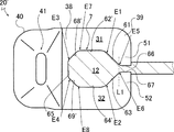
- the metal element 20 has an outer peripheral surface that connects the outer circumference of the first side surface 21 and the outer circumference of the second side surface 22. As shown in FIG. 3, the outer peripheral surface includes an upper surface 23a, a lower surface 23b, a head tip surface 23c, and leg tip surfaces 23d and 23e. The leg tip surfaces 23d and 23e are arranged so as to sandwich the fastener tape 10 vertically.
- the legs 31 and 32 are cantilever beams extending from the base end 38 connected to the head 40 to the free end 39.
- the core string holding portion 7 is composed of the legs 31 and 32 and the head portion 40.
- the core cord holding portion 7 has a restraining surface 61, 63, a core cord compression surface 62, 64, and a bottom surface 65.
- the core string compression surfaces 62, 64 and the restraint surfaces 61, 63 are arranged adjacent to each other along the extending direction of the legs 31, 32.
- the bottom surface 65 extends in the thickness direction (that is, the vertical direction) of the fastener tape 10 to connect the core string compression surfaces 62 and 64, and may be simply referred to as a connection surface.
- each of the legs 31 and 32 is provided with restraining claws 51 and 52 having restraining surfaces 61 and 63 for restraining the core cord 12 that moves away from between the pair of legs 31 and 32. ..
- the restraining surfaces 61, 63 of the pair of legs 31, 32 are gradually inclined so as to approach each other as they are separated from the head 40.
- the restraining surfaces 61 and 63 can be flat surfaces, respectively.
- the angle ⁇ formed by the plane PL1 oriented parallel to the plane PL0 on which the fastener tape 10 is present and the restraining surfaces 61 and 63 is 60 ° or less, more preferably 56 ° or less.
- the angle ⁇ formed is preferably 45 ° or more.
- An acute angle is referred to as the angle to be formed. It is possible to achieve both the attachment strength of the metal element 20 to the core string 12 and the smooth molding of the Y bar from the metal wire.
- the angle ⁇ formed by the flat surface PL1 and the restraining surfaces 61 and 63 is 90 °, the restraining force of the restraining surfaces 61 and 63 is enhanced, but it is not easy to form the Y bar from the metal wire.
- the pair of legs 31 and 32 are provided with core cord compression surfaces 62 and 64 that are gradually inclined so as to approach each other as they are separated from the restraint surfaces 61 and 63.
- the core string compression surfaces 62 and 64 extend from the restraining surfaces 61 and 63 until they reach the base end 38 (or bottom surface 65) of the legs 31 and 32.
- the thicknesses T31 and T32 of the legs 31 and 32 in the thickness direction of the fastener tape 10 are directed from the free end 39 of the legs 31 and 32 toward the base end 38 according to the inclination of the core string compression surfaces 62 and 64. Gradually increase.
- the legs 31 and 32 can have stronger resistance to the lateral pulling of the slide fastener 1.
- the closed slide fastener 1 is pulled to the opposite side in the left-right direction, and the attachment strength of the left and right metal elements 20 to the core string 12 is mainly evaluated.
- the restraining surfaces 61 and 63 of the pair of legs 31 and 32 gradually incline so as to approach each other as they are separated from the head 40.
- the restraining surfaces 61 and 63 receive the force F1 from the core string 12, and the force F2 that separates the free ends 39 of the legs 31 and 32 from each other is applied to the legs 31 and 32. It becomes easy to be given.
- the thicknesses T31 and T32 of the legs 31 and 32 gradually increase from the free end portion 39 toward the base end portion 38 due to the inclination of the core string compression surfaces 62 and 64.
- the legs 31 and 32 can withstand a larger force F2, and the expansion and expansion of the legs 31 and 32 is suppressed. That is, it is promoted to increase the lateral pulling strength of the slide fastener 1 while ensuring the ease of forming the Y bar.
- the core string holding portion 7 becomes asymmetric with respect to the plane PL3 (see the vertical plane shown by the broken line in FIG. 3), and the degree of compression of the core string 12 There is a risk of unevenness / difference.
- the plane PL0 and the plane PL3 intersect at the center of the core cord 12 (see FIG. 6). According to the study of the inventor of the present application, it is better that the legs 31 and 32 can withstand a larger force F2 than that the degree of compression of the core string 12 is uneven / different. It is expected to be effective in improving strength.
- the angle ⁇ formed by the plane PL2 oriented parallel to the plane PL0 on which the fastener tape 10 is present and the core cord compression surface 62 can be 6 ° or more and 30 ° or less, preferably 10 ° or more and 20 ° or less. An acute angle is referred to as the angle to be formed.
- ⁇ be the angle formed by the plane PL1 oriented parallel to the plane PL0 where the fastener tape 10 exists and the restraining surfaces 61 and 63, and the plane PL2 oriented parallel to the plane PL0 where the fastener tape 10 exists.
- the angle formed by the core cord compression surface 62 is ⁇ , 2.5 ⁇ ( ⁇ / ⁇ ) ⁇ 7.5 can be satisfied.
- the angle ⁇ formed by the restraining surfaces 61 and 63 and the core string compression surfaces 62 and 64 may be in the range of 100 ° to 135 °.
- the angle ⁇ formed by the core cord compression surfaces 62 and 64 and the bottom surface 65 may be in the range of 95 ° to 110 °.
- a core cord holding portion 7 having an opening in the shape is defined.
- the core string holding portion 7 has six corner portions E1 to E6. In the direction orthogonal to the plane PL0 where the fastener tape 10 is present, the distance between the corners E1 and E2> the distance between the corners E3 and E4> the distance between the corners E5 and E6 is satisfied.
- the lateral pulling strength of the slide fastener 1 can be kept within an allowable range as long as the structure of the metal element 20 according to the present embodiment is provided.
- a Y bar 200 having a Y-shaped cross section is formed from a metal wire having a circular cross section.
- a rolling die 6 as shown in the drawing can be used (Note that FIG. 4 does not show all of the dies used).
- the rolling die 6 and the Y bar 200 can be easily separated by appropriately setting the gradients of the restraining surfaces 61 and 63.
- the degree of expansion and contraction of the legs 31 and 32 should not be limited to those shown in FIG.
- the element flat plate 20 ′′ is obtained by cutting the Y bar 200, and the engaging protrusion 41 and the engaging recess 42 are formed by the molding die 8 and the receiving die 9.
- the core string 12 of the fastener tape 10 is arranged between the legs 31 and 32 of the metal element 20, and the legs 31 and 32 are plastically deformed so as to approach each other by a crimping machine. ..
- the metal element 20 is attached to the core cord 12 at a predetermined interval as shown in FIG.
- FIG. 8 shows a metal element 20'corresponding to a reference example.
- the core string holding portion 7 has an octagonal opening, and has corner portions E7 and E8 in addition to the corner portions E1 to E6.
- a non-flat core cord compression surface (flat region 62'and inclined region 68') bent at the corner E7 is formed between the restraining surface 61 and the bottom surface 65.
- a non-flat core cord compression surface (flat region 64'and inclined region 69') bent at the corner E8 is formed between the restraining surface 63 and the bottom surface 65.
- FIG. 9 shows the octagonal opening of the core string holding portion 7 of the metal element 20'shown in FIG. 8 with a broken line.
- the metal elements 20 shown in FIG. 3 have increased thicknesses T31 and T32 on the base end 38 side of the legs 31 and 32 as compared with those of the metal element 20'in FIG. It can have legs 31, 32.
- the width H2 of the opening of the core cord holding portion 7 becomes larger than the width H1, the compression of the core cord 12 is reduced, and the attachment strength of the metal element 20 to the core cord 12 is reduced. May do.
- Example 1 A Y bar was formed from a metal wire of an Al—Si alloy, and then a metal element was formed and tightened to the core cord of the fastener tape. Subsequently, the lateral pulling strength of the slide fastener was measured. A horizontal pull test was also performed on a metal element made of copper. An example is the metal element shown in FIG. A reference example is the metal element shown in FIG. The lateral pull strength of Example 1 is higher than the lateral pull strength of the reference example.
Abstract
Description
Al-Si系合金の金属線材からYバーを成形し、続いて金属製エレメントを成形し、ファスナーテープの芯紐に加締め付けた。続いて、スライドファスナーの横引き強度を測定した。丹銅製の金属製エレメントについても同様に横引き試験をした。実施例は、図3に示した金属製エレメントである。参考例は、図8に示した金属製エレメントである。

実施例1の横引き強度は、参考例の横引き強度よりも高い。
12 芯紐
20 金属製エレメント
31,32 脚部
38 基端部
39 自由端部
40 頭部
51,52 制止爪
61,63 制止面
62,64 芯紐圧迫面
65 底面
Claims (8)
- ファスナーテープ(10)の芯紐(12)に対して取り付けられた金属製エレメント(20)であって、
前記芯紐(12)を挟む一対の脚部(31,32)と、
前記一対の脚部(31,32)が連結した頭部(40)を備え、
各脚部(31,32)は、前記頭部(40)に連結した基端部(38)から自由端部(39)まで延びる片持ち梁であり、各脚部(31,32)の自由端部(39)には、前記一対の脚部(31,32)の間から離脱するように動く前記芯紐(12)を制止する制止面(61,63)を有する制止爪(51,52)が設けられ、前記一対の脚部(31,32)の前記制止面(61,63)は、前記頭部(40)から離間するに応じて互いに接近するように徐々に傾斜し、
前記頭部(40)は、同一軸線上に係合突起(41)と係合凹部(42)を有するようにカップ状に形状付けられ、前記係合突起(41)は、前記頭部(40)及び前記脚部(31,32)に亘る範囲で平坦に形成された前記金属製エレメント(20)の第1側面(21)から突出し、前記係合凹部(42)は、前記頭部(40)及び前記脚部(31,32)に亘る範囲で平坦に形成された前記金属製エレメント(20)の第2側面(22)から窪み、前記第2側面(22)が前記第1側面(21)の反対側に設けられ、
前記一対の脚部(31,32)には、前記制止面(61,63)から離間するに応じて互いに接近するように徐々に傾斜する芯紐圧迫面(62,64)が設けられ、各芯紐圧迫面(62,64)は、前記制止面(61,63)から前記脚部(31,32)の基端部(38)に到達するまで延び、
前記ファスナーテープ(10)の厚み方向における前記脚部(31,32)の厚み(T31,T32)は、少なくとも前記芯紐圧迫面(62,64)の傾斜に応じて、前記脚部(31,32)の自由端部(39)から基端部(38)に向けて漸増する、金属製エレメント。 - 前記ファスナーテープ(10)が存在する平面(PL0)に対して平行に配向された平面(PL1)と前記制止面(61,63)とのなす角(θ)が60°以下である、及び/又は、
前記ファスナーテープ(10)が存在する平面(PL0)に対して平行に配向された平面(PL2)と前記芯紐圧迫面(62)のなす角(α)が6°以上30°以下である、請求項1に記載の金属製エレメント。 - 前記ファスナーテープ(10)が存在する平面(PL0)に対して平行に配向された平面(PL1)と前記制止面(61,63)とのなす角をθとし、前記ファスナーテープ(10)が存在する平面(PL0)に対して平行に配向された平面(PL2)と前記芯紐圧迫面(62)のなす角をαとする時、2.5<(θ/α)<7.5を満足する、請求項1又は2に記載の金属製エレメント。
- 前記制止面(61,63)と前記芯紐圧迫面(62,64)のなす角(β)が、100°~135°の範囲内である、請求項1乃至3のいずれか一項に記載の金属製エレメント。
- 一方の脚部(31)における前記制止爪(51)の頂面(66)と前記制止面(61)の境界(E5)と他方の脚部(32)における前記制止爪(52)の頂面(67)と前記制止面(63)の境界(E6)を結ぶように仮想線(L1)を引く時、6角形状の開口を有する芯紐保持部(7)が画定される、請求項1乃至4のいずれか一項に記載の金属製エレメント。
- 前記第1及び第2側面(21,22)がせん断加工された面である、請求項1乃至5のいずれか一項に記載の金属製エレメント。
- 前記金属製エレメント(20)は、Alを含有する、請求項1乃至6のいずれか一項に記載の金属製エレメント。
- 請求項1乃至7のいずれか一項に記載の金属製エレメントを備えたスライドファスナー。
Priority Applications (7)
| Application Number | Priority Date | Filing Date | Title |
|---|---|---|---|
| CN201980099904.5A CN114340440A (zh) | 2019-10-10 | 2019-10-10 | 金属制链牙以及拉链 |
| US17/767,484 US20230068548A1 (en) | 2019-10-10 | 2019-10-10 | Metallic element and slide fastener |
| JP2021551058A JP7206411B2 (ja) | 2019-10-10 | 2019-10-10 | 金属製エレメント及びスライドファスナー |
| PCT/JP2019/040109 WO2021070345A1 (ja) | 2019-10-10 | 2019-10-10 | 金属製エレメント及びスライドファスナー |
| BR112022002487A BR112022002487A2 (pt) | 2019-10-10 | 2019-10-10 | Elemento metálico e fecho de correr |
| EP19948380.1A EP4042898A4 (en) | 2019-10-10 | 2019-10-10 | METAL ELEMENT AND ZIPPER |
| MX2022004222A MX2022004222A (es) | 2019-10-10 | 2019-10-10 | Elemento metalico y cierre de cremallera. |
Applications Claiming Priority (1)
| Application Number | Priority Date | Filing Date | Title |
|---|---|---|---|
| PCT/JP2019/040109 WO2021070345A1 (ja) | 2019-10-10 | 2019-10-10 | 金属製エレメント及びスライドファスナー |
Publications (1)
| Publication Number | Publication Date |
|---|---|
| WO2021070345A1 true WO2021070345A1 (ja) | 2021-04-15 |
Family
ID=75437834
Family Applications (1)
| Application Number | Title | Priority Date | Filing Date |
|---|---|---|---|
| PCT/JP2019/040109 WO2021070345A1 (ja) | 2019-10-10 | 2019-10-10 | 金属製エレメント及びスライドファスナー |
Country Status (7)
| Country | Link |
|---|---|
| US (1) | US20230068548A1 (ja) |
| EP (1) | EP4042898A4 (ja) |
| JP (1) | JP7206411B2 (ja) |
| CN (1) | CN114340440A (ja) |
| BR (1) | BR112022002487A2 (ja) |
| MX (1) | MX2022004222A (ja) |
| WO (1) | WO2021070345A1 (ja) |
Citations (3)
| Publication number | Priority date | Publication date | Assignee | Title |
|---|---|---|---|---|
| JP3917452B2 (ja) | 2002-04-11 | 2007-05-23 | Ykk株式会社 | スライドファスナーの務歯形成用金属線材と同金属線材から形成されるスライドファスナー用務歯 |
| JP3198065U (ja) * | 2014-07-18 | 2015-06-11 | 俊▲彦▼ 鍾 | 線ファスナ |
| WO2019043851A1 (ja) * | 2017-08-30 | 2019-03-07 | Ykk株式会社 | スライドファスナー用エレメント |
Family Cites Families (22)
| Publication number | Priority date | Publication date | Assignee | Title |
|---|---|---|---|---|
| US2075763A (en) * | 1937-03-30 | Method of making same | ||
| USRE21325E (en) * | 1940-01-16 | Sude fastener | ||
| US1219881A (en) * | 1914-08-27 | 1917-03-20 | Hookless Fastener Co | Separable fastener. |
| US1814244A (en) * | 1928-05-18 | 1931-07-14 | Shoe Hardware Company | Method of making interlocking elements from sheet material |
| US1983070A (en) * | 1932-08-15 | 1934-12-04 | Hookless Fastener Co | Slide fastener and method of making same |
| US2075762A (en) * | 1933-07-10 | 1937-03-30 | Hookless Fastener Co | Separable interlocking fastener and method of making same |
| US2045884A (en) * | 1933-07-10 | 1936-06-30 | Hookless Fastener Co | Apparatus and method for assembling separable interlocking fasteners |
| US2108009A (en) * | 1934-06-22 | 1938-02-08 | Joy Fastener Company | Slide fastener |
| US2622295A (en) * | 1949-02-05 | 1952-12-23 | Conmar Prod Corp | Slide fastener |
| BR7601149A (pt) * | 1975-02-27 | 1976-09-14 | Yoshida Kogyo Kk | Processo de fabricacao e elemento de acoplamento para fechos corredicos |
| US6467136B1 (en) * | 1994-10-07 | 2002-10-22 | Neil Deryck Bray Graham | Connector assembly |
| US5713110A (en) * | 1996-10-01 | 1998-02-03 | D. Swarovski & Co. | Zipper closure with decorative stones |
| JP4215660B2 (ja) * | 2004-02-25 | 2009-01-28 | Ykk株式会社 | 金属製のスライドファスナー用エレメント |
| DE602008005212D1 (de) * | 2007-07-10 | 2011-04-14 | Ykk Corp | Metallisches, doppelseitiges Element und Reißverschluss |
| WO2009128136A1 (ja) * | 2008-04-14 | 2009-10-22 | Ykk株式会社 | 金属製片面務歯及び両開き式スライドファスナー |
| GB0914903D0 (en) * | 2009-08-26 | 2009-09-30 | Ykk Europ Ltd | Slide fastener with flat elements |
| KR101356242B1 (ko) * | 2009-09-11 | 2014-01-28 | 와이케이케이 가부시끼가이샤 | 역방향 개방 슬라이드 파스너 |
| JP5460862B2 (ja) * | 2010-04-28 | 2014-04-02 | Ykk株式会社 | 金属製両面務歯及びスライドファスナー |
| WO2013080302A1 (ja) * | 2011-11-29 | 2013-06-06 | Ykk株式会社 | 金属製ファスナーエレメント |
| WO2014112100A1 (ja) * | 2013-01-18 | 2014-07-24 | Ykk株式会社 | ファスナーエレメント及びファスナーストリンガー |
| EP3332664B1 (en) * | 2015-08-05 | 2020-10-07 | YKK Corporation | Fastener stringer, slide fastener, and staking machine |
| KR101740302B1 (ko) * | 2015-08-24 | 2017-06-15 | 케이피피지퍼 주식회사 | 슬라이드 파스너 및 그의 제조방법 |
-
2019
- 2019-10-10 BR BR112022002487A patent/BR112022002487A2/pt unknown
- 2019-10-10 MX MX2022004222A patent/MX2022004222A/es unknown
- 2019-10-10 WO PCT/JP2019/040109 patent/WO2021070345A1/ja unknown
- 2019-10-10 JP JP2021551058A patent/JP7206411B2/ja active Active
- 2019-10-10 EP EP19948380.1A patent/EP4042898A4/en active Pending
- 2019-10-10 US US17/767,484 patent/US20230068548A1/en active Pending
- 2019-10-10 CN CN201980099904.5A patent/CN114340440A/zh active Pending
Patent Citations (3)
| Publication number | Priority date | Publication date | Assignee | Title |
|---|---|---|---|---|
| JP3917452B2 (ja) | 2002-04-11 | 2007-05-23 | Ykk株式会社 | スライドファスナーの務歯形成用金属線材と同金属線材から形成されるスライドファスナー用務歯 |
| JP3198065U (ja) * | 2014-07-18 | 2015-06-11 | 俊▲彦▼ 鍾 | 線ファスナ |
| WO2019043851A1 (ja) * | 2017-08-30 | 2019-03-07 | Ykk株式会社 | スライドファスナー用エレメント |
Also Published As
| Publication number | Publication date |
|---|---|
| CN114340440A (zh) | 2022-04-12 |
| JPWO2021070345A1 (ja) | 2021-04-15 |
| BR112022002487A2 (pt) | 2022-04-26 |
| MX2022004222A (es) | 2022-05-03 |
| JP7206411B2 (ja) | 2023-01-17 |
| EP4042898A1 (en) | 2022-08-17 |
| EP4042898A4 (en) | 2023-01-04 |
| US20230068548A1 (en) | 2023-03-02 |
Similar Documents
| Publication | Publication Date | Title |
|---|---|---|
| EP2014188B1 (en) | Metallic double-sided element and slide fastener | |
| US8418326B2 (en) | Metallic one-side teeth and two-way slide fastener | |
| JP6220080B2 (ja) | ファスナーエレメント、ファスナーストリンガー及びスライドファスナー | |
| US20130007993A1 (en) | Metal Double-Sided Tooth and Slide Fastener | |
| TW200536494A (en) | Metallic slide fastener element and method for manufacturing the same | |
| US7788773B2 (en) | Double-sided engaging element for slide fastener | |
| TW201315405A (zh) | 拉鏈 | |
| JP2008125737A (ja) | スライドファスナー用下止 | |
| EP2749183B1 (en) | Fastener element | |
| WO2021070345A1 (ja) | 金属製エレメント及びスライドファスナー | |
| JP3194534U (ja) | スライドファスナーの止具、及び止具を使用したスライドファスナー | |
| KR101740302B1 (ko) | 슬라이드 파스너 및 그의 제조방법 | |
| WO2014112100A1 (ja) | ファスナーエレメント及びファスナーストリンガー | |
| WO2011161802A1 (ja) | ベルト装着部の構造 | |
| EP2793634B1 (en) | Fastener element for a slide fastener, and methods for the manufacture thereof | |
| TWI396513B (zh) | Metal single-sided chain teeth and left and right double-open zipper | |
| CN110062590B (zh) | 拉链链牙及拉链链牙带 | |
| JP6708500B2 (ja) | 積層メタルガスケットの締結構造 | |
| JP2006149707A (ja) | スライドファスナーチエン | |
| JP2012041074A (ja) | 結束バンド |
Legal Events
| Date | Code | Title | Description |
|---|---|---|---|
| 121 | Ep: the epo has been informed by wipo that ep was designated in this application |
Ref document number: 19948380 Country of ref document: EP Kind code of ref document: A1 |
|
| ENP | Entry into the national phase |
Ref document number: 2021551058 Country of ref document: JP Kind code of ref document: A |
|
| REG | Reference to national code |
Ref country code: BR Ref legal event code: B01A Ref document number: 112022002487 Country of ref document: BR |
|
| NENP | Non-entry into the national phase |
Ref country code: DE |
|
| ENP | Entry into the national phase |
Ref document number: 112022002487 Country of ref document: BR Kind code of ref document: A2 Effective date: 20220209 |
|
| ENP | Entry into the national phase |
Ref document number: 2019948380 Country of ref document: EP Effective date: 20220510 |