WO2021065896A1 - 医療器具及び医療器具セット - Google Patents
医療器具及び医療器具セット Download PDFInfo
- Publication number
- WO2021065896A1 WO2021065896A1 PCT/JP2020/036860 JP2020036860W WO2021065896A1 WO 2021065896 A1 WO2021065896 A1 WO 2021065896A1 JP 2020036860 W JP2020036860 W JP 2020036860W WO 2021065896 A1 WO2021065896 A1 WO 2021065896A1
- Authority
- WO
- WIPO (PCT)
- Prior art keywords
- medical device
- end portion
- fusion promoting
- fusion
- curved surface
- Prior art date
Links
Images


Classifications
-
- A—HUMAN NECESSITIES
- A61—MEDICAL OR VETERINARY SCIENCE; HYGIENE
- A61B—DIAGNOSIS; SURGERY; IDENTIFICATION
- A61B17/00—Surgical instruments, devices or methods, e.g. tourniquets
- A61B17/11—Surgical instruments, devices or methods, e.g. tourniquets for performing anastomosis; Buttons for anastomosis
Definitions
- the present invention relates to a medical device and a medical device set.
- Various methods and medical instruments are used in the technique of joining living organs.
- a method of suturing a living organ with a biodegradable suture or a mechanical anastomosis device for anastomosis with a stapler see Patent Document 1.
- the method of using is proposed.
- the joint force between biological organs at the joint can be increased as compared with the method using sutures, which reduces the risk of suture failure. Will be possible.
- the degree of progression of fusion at the junction also depends on the condition of the biological tissue at the junction target site (joint site) of the patient. Therefore, for example, even when a joining device as described in Patent Document 1 is used, the risk of suture failure may not be sufficiently reduced depending on the condition of the patient's living tissue.
- an object of the present invention is to provide a fusion promoting device capable of reducing the risk of suture failure after surgery or the like.
- One aspect of the present invention is a medical device including a deployable portion.
- the unfolded portion includes a curved surface including a first end portion and a second end portion provided on the side opposite to the first end portion, and is a living tissue when the first end portion and the second end portion are brought into contact with each other. It is configured to be able to form a semi-closed space that can surround the fusion promoting device that promotes fusion.
- a medical device set having the above medical device and a fusion promoting device.
- the risk of suture failure after surgery or the like can be reduced.
- FIG. 3 is a perspective view showing a tip of a first engaging instrument and a second engaging instrument constituting the medical device according to FIG. 1. It is a perspective view which shows the state which the fusion promotion device is inserted through the shaft of the 2nd engaging device which constitutes a medical device. It is a side view of FIG. It is sectional drawing which shows the through hole in the fusion promotion device of FIG. It is a perspective view which shows the state which surrounded the fusion promotion device with the medical device shown in FIG. It is a perspective view which shows the medical instrument. It is a perspective view which shows the developed state of the medical device shown in FIG. 7.
- FIG. 1 It is sectional drawing which shows the positioning part which comprises the medical device. It is a flowchart which shows each procedure of the treatment method using a fusion promotion device. It is a flowchart which shows the procedure of embodiment (colon anastomosis) of a treatment method. It is a schematic cross-sectional perspective view for demonstrating colorectal anastomosis. It is a figure which shows the vicinity of the abdomen (around the navel) of a patient in which a fusion promotion device is placed. It is a schematic cross-sectional view for demonstrating colorectal anastomosis. It is a schematic side view for demonstrating colorectal anastomosis.
- ⁇ First Embodiment> 1 to 9 are diagrams provided for explaining the fusion promoting device 100 and the medical device 400 according to the first embodiment of the present invention.
- 10 to 16 are views for explaining the case of performing gastrointestinal anastomosis using the large intestine as an example using the fusion promoting device 100.
- the fusion promoting device 100 and the medical device 400 can be collectively referred to as the medical device set 1.
- the fusion promoting device 100 can be applied to a procedure for joining predetermined biological organs (for example, gastrointestinal anastomosis) as shown in FIGS. 12 to 16.
- predetermined biological organs for example, gastrointestinal anastomosis
- FIGS. 12 to 16 As will be described later, in the description of the present specification, the large intestine anastomosis technique will be described as an example of the procedure using the fusion promoting device 100, but the site where the fusion promoting device according to the present invention can be used is not limited to the large intestine.
- the fusion promoting device 100 is used when the first jointed portion such as the large intestine and the second joined portion are joined by the medical device 200.
- the medical device 200 will be described in the description of the medical device set 1.
- the medical device 200 joins a first jointed portion in a living tissue and a second joined portion facing the first joined portion.
- the medical device 200 includes a first engaging device 210 and a second engaging device 270 capable of sandwiching the main body portion 10 through the first joined portion and the second joined portion.
- the first engaging instrument 210 can be brought into contact with the first joined portion, and the second engaging instrument 270 is configured to be able to come into contact with the second joined portion. Details will be described later.
- the first engaging device 210 may be referred to as a trocar and the second engaging device 270 may be referred to as an anvil.
- the first engaging instrument 210 includes a long member 220, a positioning portion 230, a discharging portion 240, a punching portion 250, and an operating portion 260.
- the long member 220 corresponds to the main body of the first engaging device 210. As shown in FIG. 2, the long member 220 includes a space S in which the shaft of the positioning portion 230 can be relatively moved back and forth at the tip in the longitudinal direction.
- the longitudinal direction at the tip of the long member 220 is defined as the direction X.
- the long member 220 has a hollow circular cross section intersecting the direction X.
- the long member 220 extends linearly in the longitudinal direction and has a bent portion. However, if the anastomosis function and the punching function described later can be realized, the long member does not have a bent portion. May be good.
- the positioning unit 230 includes a long shaft. As shown in FIG. 2, the shaft of the positioning portion 230 is configured to be relatively movable back and forth from the space S at the tip of the long member 220 in the longitudinal direction.
- the discharge unit 240 is configured to be capable of releasing a plurality of staples that join the first bonded portion and the second bonded portion.
- the discharge portion 240 is formed in a substantially disk shape on the tip end side in the longitudinal direction of the long member 220.
- the discharge portion 240 is configured by providing a plurality of staple discharge points along the circumferential direction ⁇ at the tip of the long member 220.
- the plane direction intersecting the longitudinal direction at the tip of the long member 220 is defined as the direction YZ
- the radial direction or the radial direction is defined as the radial direction r
- the circumferential direction or the angular direction is defined as the circumferential direction ⁇ .
- the punching portion 250 is arranged at the tip of the long member 220 inward in the radial direction r than the discharging portion 240, and is configured to punch inward in the radial direction of the first bonded portion and the second bonded portion. ing. As shown in FIG. 2, the punching portion 250 is configured to include an annular blade that punches the first bonded portion and the second bonded portion inward in the radial direction r than the discharging portion 240.
- the shape of the punched portion 250 can be formed into a perfect circle when viewed in a plan view from the longitudinal direction, but the shape of the punched portion 250 may be an ellipse or the like in addition to the above as long as the portion unnecessary for promoting fusion is punched out.
- the operation unit 260 is configured so that the positioning unit 230, the discharge unit 240, and the punching unit 250 can be operated.
- the operation unit 260 includes a rotating unit 261 and a handle 262.
- the rotating portion 261 is provided at the proximal end portion (base end side) of the long member 220 in the longitudinal direction.
- the rotating portion 261 is configured to be rotatable with respect to the long member 220 with the longitudinal direction on the base end side of the long member 220 as the rotation axis.
- the rotating portion 261 is rotated with respect to the long member 220 to form the first engaging tool 210 and the second engaging tool 270. Is configured so that they can be relatively close and separated.
- the handle 262 is configured to be grippable by the user together with the base end portion (base end side) of the long member 220.
- the handle 262 is rotatably connected to the elongated member 220 by a rotating shaft 263.
- the handle 262 rotates around the rotating shaft 263 and comes relatively close to the elongated member 220 when gripped by the user. As a result, the staples are discharged from the discharging portion 240, and the annular blade of the punching portion 250 can be projected from the tip of the long member 220.
- the second engaging device 270 is configured so that the main body 10 of the fusion promoting device 100 can be sandwiched between the first joined portion and the second joined portion.
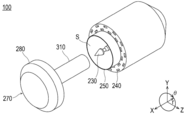
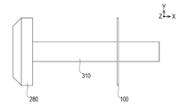
- the second engaging device 270 includes a head 280, a contact portion 290, and a shaft 310 as shown in FIGS. 3 and 4.
- the head 280 is arranged adjacent to the long member 220 of the first engaging device 210, particularly on the tip end side, when the first engaging device 210 and the second engaging device 270 are engaged with each other.
- the head 280 is configured to have a substantially disk shape as shown in FIGS. 2 and 3, and the cross-sectional shape is configured to be the same as or similar to the circular shape of the long member 220.
- the contact portion 290 is configured to be able to contact a plurality of staples discharged from the discharge portion 240.
- the contact portion 290 is provided on the side of the first engaging device 210 in the axial direction of the head 280 (the plate thickness direction, see the direction X in FIG. 3).
- the contact portion 290 is configured so as to be able to contact a plurality of staples discharged from the discharge portion 240.
- the staples released from the discharging portion 240 are brought into contact with each other at the contacting portion 290 and deformed to join the first bonded portion and the second bonded portion.
- the shaft 310 is configured to be engageable with the shaft of the positioning portion 230, and is provided for engaging the first engaging instrument 210 and the second engaging instrument 270.
- the shaft 310 is configured to extend axially from the side of the first engaging device 210 in the axial direction (direction X) of the head 280.
- the shaft 310 has a circular cross section perpendicular to the longitudinal direction in the present embodiment.
- the shaft 310 is provided with a space for accommodating the shaft of the positioning portion 230 of the first engaging device 210.
- the shaft 310 is configured to fit the shaft of the positioning portion 230, which enables the alignment of the first engaging instrument 210 and the second engaging instrument 270.
- the fusion promoting device 100 includes a main body portion 10, a reinforcing portion 20, and a hole portion 30.
- the main body portion 10 is formed in a sheet shape, and promotes fusion of the living tissue when joining the first joined portion in the living tissue and the second joined portion facing the first joined portion.
- the main body portion 10 is formed in a circular shape as an example, and includes a plurality of through holes 11 formed so as to be inserted in the thickness direction (direction X) of the circular shape.
- the size of the through hole 11 of the main body 10 is preferably 0.1 to 6 mm, more preferably 0.3 to 4 mm, and further preferably 0.6 to 1.5 mm.
- the main body 10 can be configured such that the ratio of the dimension D of the through hole 11 to the pitch P is 0.25 or more and less than 40.
- the main body 10 can be made of a biodegradable material.
- the constituent material of the main body 10 is not particularly limited, and examples thereof include biodegradable resins.
- polystyrene resin is selected from the group consisting of (1) aliphatic polyester, polyester, polyacid anhydride, polyorthoester, polycarbonate, polyphosphazene, polyphosphate ester, polyvinyl alcohol, polypeptide, polysaccharide, protein, and cellulose.
- Polymer (2) A copolymer composed of one or more monomers constituting the above (1) and the like can be mentioned.
- the biodegradable sheet is selected from the group consisting of aliphatic polyesters, polyesters, polyacid anhydrides, polyorthoesters, polycarbonates, polyphosphazenes, polyphosphates, polyvinyl alcohols, polypeptides, polysaccharides, proteins, and celluloses. It preferably contains at least one biodegradable resin selected from the group consisting of a polymer and a copolymer composed of one or more monomers constituting the polymer.
- the reinforcing portion 20 is used to suppress twisting, misalignment, breakage, etc. of the fusion promoting device 100 when the fusion promoting device 100 is placed between the first bonded portion and the second bonded portion by the medical device 200.
- the reinforcing portion 20 includes an inner reinforcing portion 21 and an outer reinforcing portion 22.
- the inner reinforcing portion 21 is formed along the inner peripheral edge in the hollow circular shape of the main body portion 10
- the outer reinforcing portion 22 is formed along the outer peripheral edge in the hollow circular shape of the main body portion 10.
- the inner reinforcing portion 21 and the outer reinforcing portion 22 are configured so as not to have a through hole 11 in the main body portion 10.
- the specific shape of the reinforcing portion 20 is not limited to the above, and the position may not be the inner peripheral edge or the outer peripheral edge as long as the twisting or shifting of the fusion promoting device 100 can be prevented or suppressed and the strength can be improved.
- the hole 30 is configured to be insertable into the shaft 310 of the medical device 200 when anastomosing biological tissue via the fusion promoting device 100 using a medical device 200 including a second engaging device 270 with a shaft 310. doing.
- the hole portion 30 has a substantially circular shape when viewed from the axial direction in the present embodiment.
- fibers containing the above-mentioned biodegradable material are arranged in a circumferential shape in the portion of the through hole 11 of the main body 10, and similar fibers are arranged in the radial direction to make a circumference.
- a method is conceivable in which the shaped fibers and the fibers in the radial direction are woven together.
- the method for producing the fiber made of biodegradable resin include an electrospinning method (electrospinning method / electrostatic spinning method) and a melt blow method.
- electrospinning method electrospinning method / electrostatic spinning method
- melt blow method for the main body 10 only one of the above methods may be selected, or two or more thereof may be appropriately combined.
- the main body 10 induces a biological reaction by a constituent material such as a biodegradable resin constituting the main body 10.
- the main body 10 induces the expression of biological components such as fibrin by this action.
- the biological components induced in this way can promote fusion by accumulating so as to penetrate through the through hole 11 of the main body 10. Therefore, by arranging the main body 10 of the fusion promoting device 100 between the biological organs to be joined, the fusion is promoted by the above mechanism.
- the medical device 400 is configured to be able to surround the fusion promoting device 100 that promotes the fusion of living tissues. As shown in FIG. 6 and the like, the medical device 400 includes a deploying portion 410, a connecting portion 420, a regulating member 430, and a positioning portion 440.
- the unfolding portion 410 includes a curved surface 411, a first end portion 412, a second end portion 413, openings 414, 415, and a semi-closed space 416.
- the curved surface 411 includes a first end portion 412 and a second end portion 413, and is configured to form a part of a hollow sphere in the present embodiment.
- the curved surface 411 is made transparent like vinyl so that the state of the fusion promoting device 100 arranged inside can be easily visually recognized.
- the curved surface 411 is configured to be expandable by providing a first end portion 412 and a second end portion 413.
- the first end portion 412 and the second end portion 413 can be configured like a generatrix forming a spherical surface as an example.
- the second end portion 413 is located on the opposite side of the developed curved surface 411 from the first end portion 412 as shown in FIG.
- the curved surface 411 forms a semi-closed space 416 capable of surrounding the fusion promoting device 100 when the first end portion 412 and the second end portion 413 are brought into contact with each other.
- the curved surface 411 can be configured such that the first end portion 412 partially forms a spherical surface when the first end portion 412 and the second end portion 413 are overlapped with each other, but the curved surface 411 may be irregular or irregular depending on the material. It may have a non-regular shape.
- the first end portion 412 and the second end portion 413 are configured as end portions when the spherical surface is unfolded.
- the first end portion 412 and the second end portion 413 are strip-shaped rather than extremely small regions such as linear. It is preferable to configure it as an area where a certain degree of area can be conceived.
- a member such as a cover cloth or the like is used. May be provided.
- the openings 414 and 415 are formed on a substantially hemispherical curved surface 411 when the fusion promoting device 100 is surrounded by the medical device 400.
- the openings 414 and 415 correspond to a portion where the semi-closed space 416 communicates with the outside in a state where the first end portion 412 and the second end portion 413 are in contact with each other.
- the openings 414 and 415 are formed like a cut portion when a hollow spherical shape is cut, and the opening 414 has a shorter peripheral length than the opening 415 in the present embodiment.
- the opening 414 can fix the medical device 400 together with the fusion promoting device 100 to the living tissue in a state of surrounding the fusion promoting device 100 by shortening the peripheral length of the opening by the regulating member 430 described later.
- the semi-closed space 416 is formed radially inward from the curved surface 411 in a state where the first end portion 412 and the second end portion 413 are overlapped with each other.
- the semi-closed space 416 communicates with the outside through openings 414 and 415.
- the connecting portion 420 is configured to connect the first end portion 412 and the second end portion 413 in a state where the semi-closed space 416 is formed by the curved surface 411.
- the connecting portion 420 is configured separately from the deploying portion 410 in the present embodiment.
- the connecting portion 420 is a thread or the like capable of suturing the first end portion 412 and the second end portion 413 of the curved surface 411 in a state where the first end portion 412 and the second end portion 413 are in contact with each other. It can be configured to include one long member.
- the regulating member 430 is configured to regulate the size of the opening 414. Thereby, the medical device 400 can be fixed to the living tissue together with the fusion promoting device 100 in a state where the fusion promoting device 100 is surrounded by the medical device 400.
- the regulating member 430 is preferably a long member such as the first long member of the connecting portion 420, and more preferably a wide and stretchable member such as a vessel tape can be used.
- the regulating member 430 is configured to include a second long member arranged along the edge of the opening 414 in the unfolding portion 410 in the present embodiment. As an example, the regulating member 430 can regulate the curved surface 411 of the deploying portion 410 so that the inner diameter is smaller than the outer diameter of the head 280 of the second engaging device 270 of the medical device 200 or the biological tissue such as the intestinal tract.
- the positioning portion 440 is provided to position the regulating member 430 in the vicinity of the opening 414 of the curved surface 411.
- the positioning portion 440 can be formed so as to cover the regulating member 430 together with the curved surface 411 at a part of the edge portion of the opening 414 of the developing portion 410 as shown in FIG.
- a treatment method using the fusion promoting device 100 will be described.
- 10 and 11 are flowcharts showing each procedure of the treatment method using the fusion promoting device 100.
- 12 to 16 are schematic views for explaining colorectal anastomosis.
- a sheet-shaped main body portion 10 that promotes fusion of living tissues between one first joined site and the other second joined site, which are the objects to be joined of living organs, is formed. It includes arranging the fusion promoting device 100 to be provided (S11). The treatment method is that at least a part of the main body 10 of the fusion promoting device 100 is arranged between one first joined site and the other second joined site, and one first joined site and the other It includes joining with the second jointed portion (S12).
- the living organ to be joined by the treatment method and the joining site in the living organ are not particularly limited and can be arbitrarily selected.
- colon anastomosis will be described as an example.
- arranging a fusion promoting device between living organs means that the healing promoting device is in direct or indirect contact with the living organ. It can mean that it is placed.
- the above description may mean that the fusion promoting device is arranged in a state where a spatial gap is formed between the living organ and the living organ. Further, in the above description, the fusion promoting device is arranged in both states (for example, the fusion promoting device is in contact with one biological organ and the fusion promoting device is not in contact with the other biological organ). To be done) can mean.
- peripheral does not define a strict range (region), but a predetermined range (region) as long as the purpose of treatment (bonding between biological organs) can be achieved. Means.
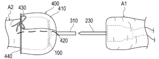
- the biological organ to be joined is the large intestine that has been cut due to the excision of the cancer tumor.
- the biological organs to be joined are the oral side A2 of the cut large intestine and the anal side A1 of the cut large intestine.
- the procedure for joining the area around the mouth of the mouth side A2 of the cut large intestine (second joint site) and a part of the intestinal wall of the anal side A1 of the cut large intestine (first joint site) will be described. explain.
- the treatment method according to the present embodiment is to dispose the fusion promoting device 100 between the mouth of the large intestine and the intestinal wall of the large intestine (S101), the mouth of the large intestine and the intestine of the large intestine. Includes making the walls relatively close (S102).
- the treatment method is to sandwich the main body 10 of the fusion promoting device 100 between the periphery of the mouth of the large intestine and the intestinal wall of the large intestine (S103), and the fusion promoting device between the periphery of the mouth of the large intestine and the intestinal wall of the large intestine. This includes joining (S104) with the main body 10 sandwiched between 100. The details will be described below.
- the surgeon forms a hole-like part called a port around the navel (the part indicated by ⁇ in FIG. 13) in FIG. 13 to inflate the patient's abdomen.
- a port around the navel the part indicated by ⁇ in FIG. 13
- two ports indicated by ⁇ are formed on the left and right sides of the navel, but the positions and numbers of the ports are merely examples and are not limited to FIG.
- the operator makes an incision around the navel indicated by x in FIG. 13, and takes out the affected part of the oral side A2 from the incision. Then, the surgeon cuts out the affected part to be operated through the port.
- the operator inserts the second engaging instrument 270 of the medical device 200 into the oral side A2 of the large intestine.
- the operator inserts the shaft 310 of the second engaging instrument 270 into the oral side A2 of the large intestine, and draws a purse stitch with the shaft 310 protruding to form the sutured portion A21.
- the outer surface of the sewn portion A21 has a shape that partially protrudes to the convex side as the sewn portion A21 is sewn.
- the operator places the fusion promoting device 100 on the oral side A2 of the large intestine (S101).
- the operator passes the shaft 310 included in the second engaging instrument 270 through the hole 30 formed in the main body 10 as shown in FIG.
- the main body 10 is deformed so that the inside of the main body 10 in the radial direction r is raised as shown in FIG. 14 according to the shape of the sutured portion A21 formed so as to be raised in the living body.
- the surgeon surrounds the fusion promoting device 100 placed on the oral side A2 of the large intestine with the medical device 400 as shown in FIG.
- the medical device 400 as an initial state in the present embodiment, a long member related to the connecting portion 420 is sutured to the deploying portion 410, and a knot is not formed in a state where the regulating member 430 is arranged in the positioning portion 440. It has become.
- the medical device 400 is configured to form a substantially hemispherical shape by the connecting portion 420 in a state where the first end portion 412 and the second end portion 413 overlap each other.
- the surgeon covers the biological tissue on which the fusion promoting device 100 is arranged with a substantially hemispherical curved surface 411, and surrounds the healing promoting device 100 together with a part of the biological tissue by the medical device 400. Then, the opening 414 is tied with the regulating member 430 and a knot is formed to shorten the peripheral length of the opening 414, and the fusion promoting device 100 is fixed so as not to fall off from the living tissue.
- the operator accommodates the biological tissue on the oral side A2 including the fusion promoting device 100 and the medical device 400 from the incision indicated by x in FIG. 13 into the body.
- the operator places the first engaging device 210 of the medical device 200 on the anal side A1 of the large intestine.
- a through hole A11 is formed in the anal side A1 of the large intestine.
- the rotating portion 261 is rotated so that the first engaging tool 210 and the second engaging tool 270 are relatively close to each other.
- the periphery of the mouth of the large intestine and the intestinal wall of the large intestine are relatively close to each other (S102).
- the surgeon unties the knot by the regulating member 430 immediately before sandwiching the fusion promoting device 100 between the first engaging instrument 210 and the second engaging instrument 270, and pulls the connecting portion 420 from the deploying portion 410. Remove.
- the curved surface 411 can be expanded.
- the order of unwinding the regulating member 430 and removing the connecting portion 420 may be reversed.
- the curved surface 411 is developed using forceps or the like, and the medical device 400 is removed from the fusion promoting device 100 and the biological organ.
- the removed medical device 400 is taken out of the body through a port formed near the patient's abdomen.
- connection portion 420 which is separate from the medical device 400 at this point, is also taken out of the body.
- surgeon between the first engaging instrument 210 and the second engaging instrument 270, is located around the mouth of the oral side A2 of the large intestine, the main body 10 of the fusion promoting device 100, and the anal side A1 of the large intestine.
- the periphery of the through hole A11 formed in the intestinal wall is sandwiched (S103).
- the surgeon grasps the handle 262 of the operation unit 260 of the medical device 200, that is, rotates the handle 262 around the rotation shaft 263 to bring it closer to the rotation portion 261 and causes the annular blade of the punching portion 250 to protrude. ..
- a part of the oral side A2 of the large intestine, the main body 10 and a part of the anal side A1 of the large intestine sandwiched between the first engaging device 210 and the second engaging device 270 were excised and excised.
- the periphery of the portion is joined by staples (not shown) (S104).
- the surgeon takes out the medical device 200 from, for example, the anal side A1 of the large intestine to the outside of the living body via the anus.
- the region formed inward from the outer diameter of the punched portion 250 of the first engaging device 210 is taken out of the living body together with the medical device 200.
- the portion located inward in the radial direction r than the punched portion 250 does not remain in the body and is removed.
- a joining technique for example, gastrointestinal anastomosis
- a simple method of sandwiching the sheet-shaped main body portion 10 between the first joined portion and the second joined portion is performed by a simple method of sandwiching the sheet-shaped main body portion 10 between the first joined portion and the second joined portion. The risk of subsequent suture failure can be reduced.
- the medical device 400 constituting the medical device set 1 according to the present embodiment has a deploying unit 410.
- the unfolding portion 410 includes a curved surface 411 including a first end portion 412 and a second end portion 413 provided on the opposite side of the first end portion 412.
- the unfolding portion 410 is configured to be able to form a semi-closed space 416 capable of surrounding the fusion promoting device 100 that promotes the fusion of living tissues when the first end portion 412 and the second end portion 413 are brought into contact with each other. ..
- the fusion promoting device 100 can be maintained in a state of being surrounded by the deploying unit 410 until immediately before the fusion promoting device 100 is placed in the living body. Therefore, it is possible to prevent or suppress foreign matter from adhering to the fusion promoting device 100. As described above, according to the medical device set 1, it is possible to prevent or suppress the adhesion of foreign matter to the fusion promoting device 100, and reduce the risk of suture failure after surgery or the like.
- the medical device 400 includes a connection portion 420.
- the connecting portion 420 is configured to connect the first end portion 412 and the second end portion 413 in a state where the semi-closed space 416 is formed by the curved surface 411. With this configuration, the curved surface 411 of the unfolding portion 410 can be maintained in an unexpanded state, and foreign matter can be prevented or suppressed from adhering to the fusion promoting device 100.
- the connecting portion 420 is configured to include a first long member that can be sewn in a state where the first end portion 412 and the second end portion 413 are in contact with each other. Therefore, the connection by the first long member can be released only by unsewn, and the procedure can proceed smoothly.
- the unfolding portion 410 includes an opening 414 in which the semi-closed space 416 communicates with the outside in a state where the first end portion 412 and the second end portion 413 are in contact with each other.
- the medical device 400 is configured to have a regulatory member 430 that regulates the size of the opening 414.
- the medical device 400 can be fixed to the living tissue together with the fusion promoting device 100 in a state where the fusion promoting device 100 is surrounded by the deploying portion 410, and foreign matter can be prevented or suppressed from adhering to the fusion promoting device 100.
- the regulation member 430 can include a second long member arranged along the edge of the opening 414.
- the medical device 400 can be fixed to or released from the living tissue by an operation such as tying or unwinding the second long member near the edge of the opening 414.
- the regulating member 430 at the edge of the opening 414 in the developing portion 410, it is possible to prevent or suppress the fusion promoting device 100 from being twisted or displaced with respect to the living tissue inside the medical device 400.
- the opening 415 is configured to be provided with a positioning portion 440 for positioning the regulation member 430.
- FIG. 17 is a perspective view showing the medical device 400a according to the first modification of the first embodiment.
- the medical device 400 is fixed to the living tissue by inserting a long string-shaped member as a regulating member through the positioning portion 440 and forming a knot.
- the regulating member can be configured as follows in addition to the above.
- the fusion promoting device 100, the medical device 200, the deploying unit 410, the connecting unit 420, and the positioning unit 440 constituting the medical device 400a are the same as those in the first embodiment, and thus the description thereof will be omitted.
- the restricting member 430a can be arranged in the opening 414 of the developing portion 410 in this modified example, and is formed in a substantially arcuate shape having ends 431 and 432 in the circumferential direction and exerts an elastic force in the radial direction. It is composed of elastic members. As a result, if the regulating member 430a is inserted through the positioning portion 440 and attached, the size of the opening 414 can be regulated by contracting the vicinity of the opening 414 in the radial direction by the regulating member 430a in the same manner as the regulating member 430. It is possible to prevent the fusion promoting device 100 from falling off from the living tissue.
- the procedure using the medical device 400a according to this modification is different in that the regulating member 430a of the medical device 400a is arranged in the positioning portion 440 instead of forming a knot by the regulating member 430 of the medical device 400.
- the other procedures are the same as those in the first embodiment, the description thereof will be omitted.
- the regulation member 430a is composed of an elastic member that exerts an elastic force inward in the radial direction.
- the fusion promoting device 100 can be fixed to the living tissue together with the medical device 400a, and the fusion promoting device 100 can be prevented from falling off from the living tissue in a state where the fusion promoting device 100 is surrounded.
- FIG. 18 is a perspective view showing the medical device 400b according to the second modification of the first embodiment.
- the connecting portion 420 of the medical device is a long member that is sewn through the curved surface 411 of the developing portion 410.
- the connection of the medical device can also be configured as follows.
- the fusion promoting device 100, the medical device 200, the deploying unit 410, the regulating member 430, and the positioning unit 440 constituting the medical device 400b are the same as those in the first embodiment, and thus the description thereof will be omitted.
- the connecting portion 420b constituting the medical device 400b is configured by clips provided in the openings 414 and 415 of the hemispherical curved surface 411 in this modified example.
- the knot of the regulating member 430 of the medical device 400 is untied, and instead of removing the connecting portion 420 from the curved surface 411, the knot of the regulating member 430 is untied and connected.
- the clip related to the portion 420b is removed from the curved surface 411. Since the other procedures are the same as those in the first embodiment, the description thereof will be omitted.
- the medical device 400b is configured by attaching a clip for preventing the first end portion 412 and the second end portion 413 from being separated from each other at the opening 414 and 415 at the connection portion 420b. There is. As a result, it is possible to prevent the curved surface 411 from unintentionally unfolding until the clip related to the connecting portion 420b is removed from the curved surface 411, and it is possible to prevent foreign matter from adhering to the fusion promoting device 100.
- FIG. 19 is a perspective view showing the medical device 400c according to the second embodiment.
- the connecting portion 420 is configured separately from the deploying portion 410, but the connecting portion can also be integrally configured with the deploying portion 410.
- the medical device 400c has a deploying portion 410, a connecting portion 420c, a regulating member 430, and a positioning portion 440. Since the fusion promoting device 100, the medical device 200, the deploying unit 410, the regulating member 430, and the positioning unit 440 constituting the medical device 400c are the same as those in the first embodiment, the description thereof will be omitted.
- the connecting portion 420c is integrally formed with the developing portion 410, and specifically, in this modification, it is configured to have a so-called hook-and-loop fastener structure. That is, the connecting portion 420c is configured to include a male shape 421 of the surface fastener provided at the first end portion 412 and a female shape 422 of the surface fastener provided at the second end portion 413.
- the connecting portion 420c is configured to include a male shape 421 of the surface fastener provided at the first end portion 412 and a female shape 422 of the surface fastener provided at the second end portion 413.
- the hook-and-loop fastener related to the connecting part 420c is engaged.
- the difference is that the above is released, and the rest is the same as that of the first embodiment. Therefore, detailed description will be omitted.
- connection portion 420c is configured to be integrally configured with the deployment portion 410. Therefore, it is possible to more easily perform the operation for shifting from the state in which the fusion promoting device 100 is surrounded to the state in which it is not surrounded by the deploying unit 410.
- FIG. 20 is a diagram showing the vicinity of the first end portion and the second end portion of the medical device 400d according to the first modification of the second embodiment of the present invention.
- the fusion promoting device 100, the medical device 200, the deploying unit 410, the regulating member 430, and the positioning unit 440 constituting the medical device 400d are the same as those in the first embodiment, and thus the description thereof will be omitted.
- the connecting portion 420c of the medical device 400c is composed of the male shape and the female shape of the hook-and-loop fastener, but it can also be configured as follows.
- the medical device 400d has a deploying portion 410, a connecting portion 420d, a regulating member 430, and a positioning portion 440. Since the fusion promoting device 100, the medical device 200, the deploying unit 410, the regulating member 430, and the positioning unit 440 constituting the medical device 400d are the same as those in the first embodiment, the description thereof will be omitted.
- connection portion 420d can be configured like a so-called seat belt. That is, the connecting portion 420d includes an insertion portion 423 and an engaging portion 424.
- the insertion portion 423 is provided at the first end portion 412 of the curved surface 411 and is configured to have a hole shape.
- the engaging portion 424 is configured to include a convex shape that can be switched between protrusion and retract by an elastic member and a button that can switch between protrusion and retract of the convex shape by the user.
- the hole shape of the insertion portion 423 engages with the convex shape of the engagement portion 424, and the deployment portion 410 can be maintained in a closed state. Further, the operator pushes the button of the engaging portion 424 to retract the convex shape against the elasticity of the elastic member, disengages the insertion portion 423 and the engaging portion 424, and deploys the deploying portion 410. Can be in the state of
- connection portion 420d Note that also in this modified example, the description is omitted because the usage example is the same as the first embodiment except for the handling of the connection portion 420d.
- FIG. 21 is a diagram showing a medical device 400e according to a modification 2 of the second embodiment.
- the connecting portion 420c is configured like a hook-and-loop fastener
- the connecting portion 420d is configured like a seatbelt engaging structure, but it can also be configured as follows.
- the medical device 400e has a developing portion 410e, a connecting portion 420e, a regulating member 430, and a positioning portion 440. Since the regulation member 430 and the positioning unit 440 constituting the fusion promoting device 100, the medical device 200, and the medical device 400e are the same as those in the first embodiment, the description thereof will be omitted.
- the developing portion 410e includes a curved surface 411, openings 414, 415, and a semi-closed space 416, and the first end portion and the second end portion are configured to be provided in the connecting portion 420e. Since the curved surface 411, the openings 414, 415, and the semi-closed space 416 are the same as those in the first embodiment, the description thereof will be omitted.
- the connecting portion 420e is composed of a cut line provided on the curved surface 411.
- the connecting portion 420e is configured so that the operator can separately form the first end portion and the second end portion similar to those in the first embodiment on the curved surface 411 by cutting off the cutting line related to the connecting portion 420e during the procedure. doing. That is, in this modification, the first end portion and the second end portion are integrated until they are cut off, and the first end portion and the second end portion are separated by being cut off.
- the fusion promoting device 100 is surrounded by the unfolding portion 410e of the medical device 400e in a closed state. Then, the first engaging instrument 210 and the second engaging instrument 270 of the medical device 200 are brought close to each other, and the operator cuts the cutting line related to the connecting portion 420e immediately before sandwiching the fusion promoting device 100 to form the developing portion 410e. expand. After that, since it is the same as that of the first embodiment, detailed description thereof will be omitted.
- the connecting portion 420e is formed on the curved surface 411 and is configured to include a cutting line forming the first end portion and the second end portion by being cut by the user.
- the unfolding unit 410e can be unfolded by a simple procedure without removing another part from the unfolding unit when the unfolding unit 410e is unfolded.
- the connecting portion includes a hook-and-loop fastener formed integrally with the curved surface
- the present invention is not limited to this.
- the connecting portion may be formed of a member such as starch glue, and the curved surface 411 of the developing portion 410 may be maintained in an unexpanded state until immediately before the fusion promoting device 100 is placed in the living tissue.
- the regulating member 430a has an arc shape having ends 431 and 432 in the circumferential direction and exerts an elastic force in the radial direction due to the elastic force, but the present invention is not limited to this.
- a member that exerts a magnetic force such as a magnet is arranged near the ends 431 and 432 in the regulating member of FIG. 17, and the size of the opening is regulated by attracting the ends 431 and 432 by the magnetic force. It may be configured to do so.
- FIG. 22 is a perspective view showing a medical device set 1a according to another embodiment of the present invention.
- the medical device 400f is integrally configured with the fusion promoting device 100 to form a medical device set 1a, which is also included in one embodiment of the present invention. That is, the medical device 400f constituting the medical device set 1a has a deploying portion 410f, a connecting portion 420, a regulating member 430, a positioning portion 440, and a device connecting portion 450. Since the connecting portion 420, the regulating member 430, and the positioning portion 440 have the same configurations as those of the medical device 400 of the first embodiment having the same reference numerals, the description thereof will be omitted.
- the developing portion 410f includes a curved surface 411, a first end portion 412, a second end portion 413, openings 414, 415, a semi-closed space 416, and a contact portion 417. Since the curved surface 411, the first end portion 412, the second end portion 413, the openings 414, 415, and the semi-closed space 416 are the same as the respective configurations having the same reference numerals in the medical device 400 of the first embodiment. The explanation is omitted.
- the contact portion 417 is configured as a surface provided continuously with the curved surface 411 at one end of the curved surface 411 in the axial direction.
- the contact portion 417 is configured to come into contact with the fusion promoting device 100.
- the contact portion 417 is shown as a flat surface in FIG. 22, but may not be a flat surface as long as the fusion promoting device 100 and the medical device 400f are connected by the device connecting portion 450 at least in part. It may be a curved surface or an irregular shape.
- the device connection unit 450 is configured to connect the fusion promoting device 100 and the medical device 400f in the medical device set 1a.
- the device connecting portion 450 is configured as a filamentous member like the connecting portion 420 in FIG. 22, but if the fusion promoting device and the medical device can be connected, the clip shown in FIG. 18 and the surface shown in FIG. 19 can be connected as described above. It may be composed of a fastener or the like.
- the device connection portion 450 is provided in the vicinity of the inner peripheral edge portion or the inner peripheral edge portion forming the hole 30 of the fusion promoting device 100.
- the position where the device connection portion 450 is provided is arranged radially inward from the punching diameter d (see FIG. 16) of the punching portion 250 when the fusion promoting device 100 is punched by the medical device 200.
- the fusion promoting device is sandwiched between the relevant parts of the living tissue, and when anastomosis is performed by the medical device 200, foreign matter is prevented or suppressed from adhering to the fusion promoting device 100, and surgery or the like is performed. The risk of later suture failure can be reduced.
Abstract
【課題】外科手術等の術後における縫合不全のリスクを低減する。 【解決手段】本発明に係る医療器具100は、第1端部412と第1端部と反対側に設け られた第2端部413とを含む曲面411を含み、第1端部と第2端部とを接触させた際 に生体組織の癒合を促進する癒合促進デバイスを包囲可能な半閉空間416を形成可能な 展開部410を備える。
Description
本発明は、医療器具及び医療器具セットに関する。
医療分野において生体器官を外科的手術により接合する手技(例えば消化管の吻合術)が知られている。上記のような手技が行われた場合、生体器官同士が接合された接合部における癒合の遅延が生じないことが術後の予後決定因子として重要であることが知られている。
生体器官を接合する手技では種々の方法や医療器具が用いられるが、例えば生分解性の縫合糸により生体器官を縫合する方法や、ステープラーによる吻合を行う機械式の吻合装置(特許文献1参照)を利用する方法が提案されている。特に、機械式の吻合装置を利用して吻合術を行う場合、縫合糸を用いた方法と比較して接合部における生体器官同士の接合力を高めることができるため、縫合不全のリスクを低減させることが可能になる。
しかしながら、接合部における癒合の進行の程度は、患者の接合対象部位(被接合部位)における生体組織の状態等にも依存する。そのため、例えば、特許文献1に記載されているような接合装置を使用した場合においても、患者の生体組織の状態如何によっては、縫合不全のリスクを十分に低減させることができない可能性もある。
そこで本発明は、外科手術等の術後における縫合不全のリスクを低減させることができる癒合促進デバイスを提供することを目的とする。
本発明の一態様は、展開部を備える医療器具である。展開部は、第1端部と当該第1端部と反対側に設けられた第2端部とを含む曲面を含み、第1端部と第2端部とを接触させた際に生体組織の癒合を促進する癒合促進デバイスを包囲可能な半閉空間を形成可能に構成している。また、本発明の一態様は、上記医療器具と癒合促進デバイスとを有する医療器具セットである。
本発明に係る癒合促進デバイスによれば、外科手術等の術後における縫合不全のリスクを低減できる。
以下、添付した図面を参照して、本発明の実施形態を説明する。なお、図面の説明において同一の要素には同一の符号を付し、重複する説明を省略する。また、図面の寸法比率は、説明の都合上誇張され、実際の比率とは異なる場合がある。
<第1実施形態>
図1~図9は本発明の第1実施形態に係る癒合促進デバイス100と医療器具400の説明に供する図である。図10~図16は癒合促進デバイス100を用いて大腸を一例として消化管の吻合を行う際を説明する図である。なお、本実施形態において癒合促進デバイス100と医療器具400とは、合わせて医療器具セット1と呼ぶことができる。
図1~図9は本発明の第1実施形態に係る癒合促進デバイス100と医療器具400の説明に供する図である。図10~図16は癒合促進デバイス100を用いて大腸を一例として消化管の吻合を行う際を説明する図である。なお、本実施形態において癒合促進デバイス100と医療器具400とは、合わせて医療器具セット1と呼ぶことができる。
癒合促進デバイス100は、図12~図16に示すように所定の生体器官同士を接合する手技(例えば、消化管の吻合術)に適用することができる。後述するように、本明細書の説明では癒合促進デバイス100を使用した手技の例として大腸吻合術を説明するが、本発明に係る癒合促進デバイスを使用可能な部位は大腸に限定されない。
癒合促進デバイス100は、医療デバイス200によって大腸等の第1被接合部位と第2被接合部位とを接合する際に使用される。医療器具セット1の説明にあたり医療デバイス200について説明する。
<医療デバイス>
医療デバイス200は、生体組織における第1被接合部位と第1被接合部位に対向する第2被接合部位とを接合する。医療デバイス200は、第1被接合部位及び第2被接合部位を介して本体部10を挟み込み可能な第1係合器具210と第2係合器具270を備える。第1係合器具210は第1被接合部位と当接可能であり、第2係合器具270は第2被接合部位と当接可能に構成している。詳細については後述する。第1係合器具210は、トロッカーと呼ばれる場合があり、第2係合器具270はアンビルと呼ばれる場合がある。
医療デバイス200は、生体組織における第1被接合部位と第1被接合部位に対向する第2被接合部位とを接合する。医療デバイス200は、第1被接合部位及び第2被接合部位を介して本体部10を挟み込み可能な第1係合器具210と第2係合器具270を備える。第1係合器具210は第1被接合部位と当接可能であり、第2係合器具270は第2被接合部位と当接可能に構成している。詳細については後述する。第1係合器具210は、トロッカーと呼ばれる場合があり、第2係合器具270はアンビルと呼ばれる場合がある。
<第1係合器具>
第1係合器具210は、図1、2に示すように長尺部材220と、位置決め部230と、放出部240と、打抜き部250と、操作部260と、を備える。
第1係合器具210は、図1、2に示すように長尺部材220と、位置決め部230と、放出部240と、打抜き部250と、操作部260と、を備える。
長尺部材220は、第1係合器具210の本体に相当する。長尺部材220は、図2に示すように長手方向の先端において位置決め部230のシャフトを相対的に進退移動可能な空間Sを備える。なお、本明細書において長尺部材220の先端部における長手方向を方向Xとする。長尺部材220は、方向Xに交差する断面を中空の円形状に構成している。長尺部材220は、本実施形態において長手方向に直線状に延在するとともに屈曲箇所を備えているが、後述する吻合機能と打抜き機能を実現できれば、長尺部材には屈曲箇所を設けなくてもよい。
位置決め部230は、長尺状のシャフトを備える。位置決め部230のシャフトは、図2に示すように長尺部材220の長手方向における先端において空間Sから相対的に進退移動自在に構成している。
放出部240は、第1被接合部位と第2被接合部位とを接合する複数のステープルを放出可能に構成している。放出部240は長尺部材220の長手方向における先端側において略円板状に形成している。放出部240は、長尺部材220の先端において周方向θに沿ってステープルの放出箇所を複数設けることによって構成している。なお、本明細書において長尺部材220の先端部における長手方向と交差する面方向を方向YZ、放射方向又は径方向を径方向r、周方向又は角度方向を周方向θとする。
打抜き部250は、長尺部材220の先端において放出部240よりも径方向rの内方に配置し、第1被接合部位と第2被接合部位の放射方向内方を打抜くように構成している。打抜き部250は、図2に示すように放出部240よりも径方向rの内方に第1被接合部位と第2被接合部位を打ち抜く環状のブレードを備えるように構成している。打抜き部250の形状は、長手方向から平面視した際に真円に構成できるが、癒合促進に不要な部位を打抜ければ打抜き部250の形状は上記以外にも楕円等であってもよい。
操作部260は、位置決め部230と放出部240と打抜き部250とを操作できるように構成している。操作部260は、回転部261と、ハンドル262と、を備える。
回転部261は、長尺部材220の長手方向における基端部(基端側)に設けている。回転部261は、長尺部材220の基端側における長手方向を回転軸として長尺部材220に対して回転可能に構成している。回転部261は、第2係合器具270が第1係合器具210と係合した状態において、長尺部材220に対して回転させることによって第1係合器具210と第2係合器具270とを相対的に接近離間できるように構成している。
ハンドル262は、長尺部材220の基端部(基端側)とともに使用者によって把持可能に構成している。ハンドル262は、回転軸263によって長尺部材220と回転可能に接続されている。ハンドル262は、使用者によって握られることによって回転軸263の周りに回転して長尺部材220と相対的に接近する。これにより、放出部240からステープルを放出し、長尺部材220の先端から打抜き部250の環状ブレードを突出できるように構成している。
<第2係合器具>
第2係合器具270は、第1被接合部位と第2被接合部位を介して癒合促進デバイス100の本体部10を挟み込み可能に構成している。第2係合器具270は、図3、4に示すようにヘッド280と、当接部290と、シャフト310と、を備える。
第2係合器具270は、第1被接合部位と第2被接合部位を介して癒合促進デバイス100の本体部10を挟み込み可能に構成している。第2係合器具270は、図3、4に示すようにヘッド280と、当接部290と、シャフト310と、を備える。
ヘッド280は、第1係合器具210と第2係合器具270とを係合させた際に第1係合器具210の長尺部材220の特に先端側に隣接して配置される。ヘッド280は、本実施形態において図2、3に示すように略円板形状に構成しており、断面形状が長尺部材220の円形状と同一又は類似する形状として構成している。
当接部290は、放出部240から放出される複数のステープルと当接可能に構成している。当接部290は、ヘッド280の軸方向(板厚方向、図3の方向X参照)において第1係合器具210の側に設けている。当接部290は、放出部240から放出される複数のステープルと当接可能に構成している。放出部240から放出されたステープルは当接部290で当接し、変形することによって第1被接合部位と第2被接合部位とを接合する。
シャフト310は位置決め部230のシャフトと係合可能に構成しており、これにより第1係合器具210と第2係合器具270とを係合させるために設けられる。シャフト310は、ヘッド280の軸方向(方向X)において第1係合器具210の側から軸方向に長尺状に延在するように構成している。シャフト310は、本実施形態において長手方向に直行する断面を円状に形成している。シャフト310には第1係合器具210の位置決め部230のシャフトを収容する空間を設けている。シャフト310は、位置決め部230のシャフトと嵌合するように構成しており、これにより第1係合器具210と第2係合器具270との位置合わせが可能になる。
<癒合促進デバイス>
癒合促進デバイス100は、図3に示すように本体部10と、補強部20と、孔部30と、を備える。
癒合促進デバイス100は、図3に示すように本体部10と、補強部20と、孔部30と、を備える。
<本体部>
本体部10はシート状に構成し、生体組織における第1被接合部位と第1被接合部位に対向する第2接合部位とを接合する際に生体組織の癒合を促進する。
本体部10はシート状に構成し、生体組織における第1被接合部位と第1被接合部位に対向する第2接合部位とを接合する際に生体組織の癒合を促進する。
本体部10は、図3、図5に示すように一例として円形状に形成しており、当該円形状の厚さ方向(方向X)に挿通するように形成された貫通孔11を複数備える。本体部10の貫通孔11の大きさについて例示すれば、好ましくは0.1~6mm、より好ましくは0.3~4mm、さらに好ましくは0.6~1.5mmである。本体部10は、貫通孔11の寸法DとピッチPとの比が0.25以上40未満となるように構成できる。
本体部10は、生分解性の材料で構成することができる。本体部10の構成材料について特に制限はなく、例えば、生分解性樹脂が挙げられる。
具体的には、(1)脂肪族ポリエステル、ポリエステル、ポリ酸無水物、ポリオルソエステル、ポリカーボネート、ポリホスファゼン、ポリリン酸エステル、ポリビニルアルコール、ポリペプチド、多糖、タンパク質、セルロースからなる群から選択される重合体;(2)上記(1)を構成する一以上の単量体から構成される共重合体などが挙げられる。
すなわち、生分解性シートは、脂肪族ポリエステル、ポリエステル、ポリ酸無水物、ポリオルソエステル、ポリカーボネート、ポリホスファゼン、ポリリン酸エステル、ポリビニルアルコール、ポリペプチド、多糖、タンパク質、セルロースからなる群から選択される重合体、ならびに前記重合体を構成する一以上の単量体から構成される共重合体からなる群より選択される少なくとも一種の生分解性樹脂を含むことが好ましい。
補強部20は、医療デバイス200によって癒合促進デバイス100を第1被接合部位と第2被接合部位との間に留置する際等に癒合促進デバイス100のヨレ、ずれ、破損等を抑制するために設けられる。補強部20は、図3に示すように内側補強部21と、外側補強部22と、を備える。内側補強部21は、本体部10の中空の円形状において内周縁に沿って形成し、外側補強部22は、本体部10の中空の円形状において外周縁に沿って形成している。内側補強部21及び外側補強部22は、本実施形態において本体部10において貫通孔11を設けない形状として構成している。ただし、癒合促進デバイス100のヨレやずれを防止又は抑制し、強度を向上できれば、補強部20の具体的な形状は上記に限定されず、位置も内周縁や外周縁でなくてもよい。
孔部30は、シャフト310を備えた第2係合器具270を含む医療デバイス200を用いて、癒合促進デバイス100を介して生体組織を吻合する際に医療デバイス200のシャフト310に挿通可能に構成している。孔部30は、本実施形態において軸方向から見た際に略円形状に構成している。
本体部10の製造方法について例示すれば、本体部10の貫通孔11の部分について上述した生分解性材料を含む繊維を円周状に配置し、同様の繊維を放射方向に配置して円周状の繊維と放射方向の繊維とを編み込むように一体にする方法が考えられる。生分解性樹脂からなる繊維を作製する方法としてはエレクトロスピニング法(電界紡糸法・静電紡糸法)やメルトブロー法等が挙げられる。本体部10は、上記方法のうち1種のみを選択してもよいし、2種以上を適宜組み合わせてもよい。
本体部10は、本体部10を構成する生分解性樹脂等の構成材料によって生体反応を惹起させる。本体部10は、この作用により、フィブリン等の生体成分の発現を誘導する。このようにして誘導された生体成分は、本体部10の貫通孔11を貫通するようにして集積することで、癒合を促進することができる。したがって、接合対象となる生体器官同士の間に、癒合促進デバイス100の本体部10を配置することにより、上記のメカニズムによる癒合の促進が生じる。
<医療器具>
医療器具400は、生体組織の癒合を促進する癒合促進デバイス100を包囲可能に構成している。医療器具400は、図6等に示すように展開部410と、接続部420と、規制部材430と、位置決め部440と、を備える。
医療器具400は、生体組織の癒合を促進する癒合促進デバイス100を包囲可能に構成している。医療器具400は、図6等に示すように展開部410と、接続部420と、規制部材430と、位置決め部440と、を備える。
展開部410は、図7に示すように曲面411と、第1端部412と、第2端部413と、開口部414、415と、半閉空間416と、を備える。
曲面411は第1端部412と第2端部413を含み、本実施形態において中空の球の一部を形成するように構成している。曲面411は、一例としてビニールなどのように透明に構成することで内部に配置した癒合促進デバイス100の状態を視認しやすくできる。曲面411は、第1端部412と第2端部413を設けることによって展開可能に構成している。第1端部412と第2端部413は、一例として球面を形成する母線のように構成することができる。第2端部413は、図8に示すように展開した曲面411において第1端部412と反対側に位置する。曲面411は、第1端部412と第2端部413とを接触させた際に癒合促進デバイス100を包囲可能な半閉空間416を形成する。曲面411は、第1端部412は、第1端部412と第2端部413とを重ね合わせた際に部分的に球面を形成するように構成できるが、材料に応じて不規則、又は規則性のない形状であってもよい。
第1端部412と第2端部413とは、球面を展開した際の端部として構成している。ただし、曲面411を略半球状に形成した際に端部の接合強度を一定程度確保するために第1端部412と第2端部413とは線状のような極めて小さな領域というよりも帯状のような一定程度の面積を観念できる領域として構成することが好ましい。また、第1端部412と第2端部413の少なくともいずれか一方には接続部420によって半閉空間416を形成した際の接続部420に対する接合強度を向上させるために、あて布等の部材を設けてもよい。
開口部414、415は、医療器具400によって癒合促進デバイス100を包囲した際に略半球形状の曲面411に形成される。開口部414、415は、第1端部412と第2端部413とを当接させた状態において半閉空間416が外部と通じる部位に相当する。開口部414、415は中空の球形状を切断した際の切断部のように形成され、開口部414は本実施形態において開口部415よりも周長を短く構成している。開口部414は、後述する規制部材430によって開口部の周長を短くすることによって癒合促進デバイス100を包囲した状態において医療器具400を癒合促進デバイス100とともに生体組織に固定できる。
半閉空間416は、第1端部412と第2端部413とを重ね合わせた状態において曲面411よりも径方向内方に形成される。半閉空間416は、開口部414、415を通じて外部と連通する。
接続部420は、曲面411によって半閉空間416を形成した状態において第1端部412と第2端部413とを接続するように構成している。接続部420は、本実施形態において展開部410と別体に構成している。接続部420は、本実施形態において第1端部412と第2端部413とを当接させた状態において曲面411の第1端部412と第2端部413を縫合可能な糸等の第1長尺部材を含むように構成できる。
規制部材430は、開口部414の大きさを規制するように構成している。これにより、医療器具400によって癒合促進デバイス100を包囲した状態において医療器具400を癒合促進デバイス100とともに生体組織に固定できる。規制部材430は、接続部420の第1長尺部材のように長尺部材であることが好ましく、より好ましくはベッセルテープのように幅が広くて伸縮性のある部材を用いることができる。規制部材430は、本実施形態において展開部410において開口部414の縁部に沿って配置される第2長尺部材を含むように構成している。規制部材430は、一例として展開部410の曲面411が腸管等の生体組織や医療デバイス200の第2係合器具270のヘッド280の外径よりも内径が小さくなるように規制することができる。
位置決め部440は、曲面411の開口部414の近傍において規制部材430を位置決めするために設けられる。位置決め部440は、一例として図9に示すように展開部410の開口部414の縁部の一部において曲面411とともに規制部材430を覆うように形成することができる。
<処置方法>
次に癒合促進デバイス100を用いた処置方法を説明する。図10、図11は癒合促進デバイス100を用いた処置方法の各手順を示すフローチャートである。図12~図16は大腸吻合術を説明するための模式的な図である。
次に癒合促進デバイス100を用いた処置方法を説明する。図10、図11は癒合促進デバイス100を用いた処置方法の各手順を示すフローチャートである。図12~図16は大腸吻合術を説明するための模式的な図である。
処置方法は、図10に示すように生体器官の接合対象となる一方の第1被接合部位と他方の第2被接合部位との間に生体組織の癒合を促進するシート状の本体部10を備える癒合促進デバイス100を配置すること(S11)を含む。処置方法は、一方の第1被接合部位と他方の第2被接合部位との間に癒合促進デバイス100の本体部10の少なくとも一部を配置した状態で一方の第1被接合部位と他方の第2被接合部位とを接合すること(S12)を含む。
処置方法により接合される生体器官及び生体器官における被接合部位は特に限定されず、任意に選択することができる。ただし、以下の説明では、大腸吻合術を例に挙げて説明する。
また、以下に説明する各手技において、公知の手技手順や公知の接合装置については詳細な説明を適宜省略する。
以下、本明細書の説明において「生体器官の間に癒合促進デバイスを配置する(以下、上記記載と言う)」とは、生体器官に癒合促進デバイスが直接的に又は間接的に接触した状態で配置されることを意味し得る。
また、上記記載は生体器官との間に空間的な隙間が形成された状態で癒合促進デバイスが配置されることを意味し得る。また、上記記載はその両方の状態で癒合促進デバイスが配置されること(例えば、一方の生体器官に癒合促進デバイスが接触し、他方の生体器官には癒合促進デバイスが接触していない状態で配置されること)を意味し得る。
また、本明細書の説明において「周辺」とは、厳密な範囲(領域)を規定するものではなく、処置の目的(生体器官同士の接合)を達成し得る限りにおいて、所定の範囲(領域)を意味する。
また、各処置方法において説明する手技手順は、処置の目的を達成し得る限りにおいて、順番を適宜入れ替えることが可能である。また、本明細書の説明において「相対的に接近させる」とは、接近させる対象となる2つ以上のものを、互いに接近させること、一方のみを他方のみに接近させることの両方を意味する。
本実施形態に係る処置方法において、接合対象となる生体器官は、癌腫瘍の切除に伴い切断された大腸である。具体的には、接合対象となる生体器官は、切断した大腸の口側A2と、切断した大腸の肛門側A1である。以下の説明では、切断した大腸の口側A2の口部周辺(第2被接合部位)と、切断した大腸の肛門側A1の腸壁の一部(第1被接合部位)を接合する手順を説明する。
図11に示すように、本実施形態に係る処置方法は、大腸の口部周辺と大腸の腸壁の間に癒合促進デバイス100を配置すること(S101)、大腸の口部周辺と大腸の腸壁を相対的に接近させること(S102)を含む。処置方法は、大腸の口部周辺と大腸の腸壁との間で癒合促進デバイス100の本体部10を挟み込むこと(S103)、大腸の口部周辺と大腸の腸壁との間に癒合促進デバイス100に本体部10を挟み込んだ状態で接合すること(S104)を含む。以下、詳述する。
まず、術者は、図13において臍のあたり(図13の〇で示す部分)の周囲にポートという穴のような部位を形成し、患者のお腹を膨らませる。図13では臍を挟んで左右に2か所ずつ〇で示すポートを形成しているが、あくまで例示であってポートの位置や個数は図13に限定されない。次に、術者は、図13の×で示す臍のあたりに切開部を形成し、そこから口側A2の患部を体外に取り出す。そして、術者は、ポートを介して手術を施す患部を切り取る。次に、術者は、大腸の口側A2に、医療デバイス200の第2係合器具270を挿入する。
次に、術者は、第2係合器具270のシャフト310を大腸の口側A2に挿入し、シャフト310を突出した状態で巾着縫合し、縫合部A21を形成する。縫合部A21の外表面は、縫合に伴い凸側に部分的に突出した形状となる。
次に、術者は、図14に示すように、大腸の口側A2に癒合促進デバイス100を配置する(S101)。術者は、癒合促進デバイス100を配置する際に図3に示すように第2係合器具270が備えるシャフト310を本体部10に形成された孔部30に通す。この時点で本体部10は、生体において隆起するように形成された縫合部A21の形状に合わせて本体部10の径方向rの内方が図14に示すように隆起するように変形する。
次に、術者は、図15に示すように医療器具400によって大腸の口側A2に配置した癒合促進デバイス100を包囲する。医療器具400は、本実施形態において初期状態として展開部410に接続部420に係る長尺部材を縫合しており、規制部材430が位置決め部440に配置した状態で結び目を形成していない状態となっている。また、医療器具400は、第1端部412と第2端部413とが重なった状態において接続部420によって略半球形状を形成するように構成している。術者は、癒合促進デバイス100を配置した生体組織に略半球形状の曲面411を被せ、医療器具400によって生体組織の一部とともに癒合促進デバイス100を包囲する。そして、規制部材430で開口部414を縛り、結び目を形成することによって開口部414の周長を短くし、癒合促進デバイス100が生体組織から脱落しないように固定する。
次に、術者は、図13の×で示す切開部から癒合促進デバイス100及び医療器具400を含む口側A2の生体組織を体内に収容する。次に、術者は、大腸の肛門側A1に、医療デバイス200の第1係合器具210を配置する。第1係合器具210を大腸の肛門側A1に配置することによって、大腸の肛門側A1に貫通孔A11が形成される。そして、大腸の口側A2に対して本体部10を保持した状態を維持しつつ、位置決め部230のシャフトと第2係合器具270のシャフト310とを離間した位置で係合させる。そして、回転部261を回転させて、第1係合器具210と第2係合器具270を相対的に接近させる。これにより、大腸の口部周辺と大腸の腸壁とが相対的に接近する(S102)。
術者は、図8に示すように第1係合器具210と第2係合器具270とで癒合促進デバイス100を挟み込む直前に規制部材430による結び目をほどき、接続部420を展開部410から取り外す。これにより、曲面411が展開可能な状態となる。なお、規制部材430をほどくことと、接続部420の取り外しは順番を逆転させてもよい。そして、鉗子等を用いて曲面411を展開し、癒合促進デバイス100及び生体器官から医療器具400を取り外す。取り外した医療器具400は、患者の腹部付近に形成したポートから体外に取り出す。また、この時点で医療器具400と別体となっている接続部420も体外に取り出す。次に、術者は、第1係合器具210と第2係合器具270との間で、大腸の口側A2の口部周辺、癒合促進デバイス100の本体部10、大腸の肛門側A1の腸壁に形成した貫通孔A11周辺を挟み込む(S103)。
次に、術者は、医療デバイス200の操作部260のハンドル262を握って、すなわちハンドル262を回転軸263の回りに回転させて回転部261に近づけて、打抜き部250の環状ブレードを突出させる。そして、第1係合器具210と第2係合器具270との間に挟まれた大腸の口側A2の一部、本体部10、及び大腸の肛門側A1の一部を切除し、切除した部位の周囲をステープル(図示省略)により接合する(S104)。
次に、術者は、図16に示すように、医療デバイス200を、例えば、大腸の肛門側A1から肛門を介して生体外へ取り出す。このとき、第1係合器具210の打抜き部250の外径より内方側に構成された領域を医療デバイス200とともに生体外へ取り出す。これにより、癒合促進デバイス100において打抜き部250よりも径方向rの内方に位置する部位は体内に残らず、除去される。
癒合促進デバイス100の本体部10が接合対象となる生体器官の間に挟み込まれて留置されることによって、本体部10の貫通孔11を通じて接合対象となる生体器官の癒合を促進させることができる。
このような処置方法によれば、シート状の本体部10を第1被接合部位と第2被接合部位との間に挟み込ませるという簡便な方法により、接合手技(例えば、消化管の吻合術)後の縫合不全等のリスクを低減させることができる。
以上説明したように本実施形態に係る医療器具セット1を構成する医療器具400は、展開部410を有する。展開部410は、第1端部412と第1端部412と反対側に設けられた第2端部413を含む曲面411を備える。展開部410は、第1端部412と第2端部413とを接触させた際に生体組織の癒合を促進する癒合促進デバイス100を包囲可能な半閉空間416を形成可能に構成している。
このように構成することによって癒合促進デバイス100を生体内に留置する直前まで展開部410によって癒合促進デバイス100を包囲した状態を維持できる。そのため、癒合促進デバイス100に異物が付着することを防止又は抑制できる。このように医療器具セット1によれば、癒合促進デバイス100に異物が付着することを防止又は抑制して、外科手術等の術後における縫合不全のリスクを低減できる。
また、医療器具400は接続部420を備える。接続部420は、曲面411によって半閉空間416を形成した状態において第1端部412と第2端部413とを接続するように構成している。このように構成することによって、展開部410の曲面411が展開されていない状態を維持し、癒合促進デバイス100に異物が付着することを防止又は抑制できる。
また、接続部420は、第1端部412と第2端部413とを当接させた状態において縫合可能な第1長尺部材を含むように構成している。そのため、第1長尺部材による接続を、縫合を解く程度で解除でき、手技を円滑に進めることができる。
また、展開部410は第1端部412と第2端部413とを当接させた状態において半閉空間416が外部と通じる開口部414を備える。医療器具400は、開口部414の大きさを規制する規制部材430を有するように構成している。これにより、展開部410によって癒合促進デバイス100を包囲した状態で癒合促進デバイス100とともに医療器具400を生体組織に固定し、癒合促進デバイス100に異物が付着することを防止又は抑制できる。
また、規制部材430は、開口部414の縁部に沿って配置される第2長尺部材を含むことができる。これにより、開口部414の縁部付近で第2長尺部材を結ぶ、又はほどくといった動作で医療器具400を生体組織に対して固定したり、固定を解除したりできる。また、規制部材430を展開部410の中でも開口部414の縁部に設けることによって医療器具400の内部で癒合促進デバイス100が生体組織に対してヨレやずれが生じることを防止又は抑制できる。
また、開口部415には規制部材430を位置決めする位置決め部440を設けるように構成している。これにより、規制部材430が意に反して医療器具400から外れて医療器具400が生体組織から脱落し、癒合促進デバイス100に異物が付着するリスクをより低減できる。
<第1実施形態の変形例1>
図17は第1実施形態の変形例1に係る医療器具400aを示す斜視図である。第1実施形態では規制部材として紐状の長尺部材を位置決め部440に挿通させ、結び目を形成することによって医療器具400を生体組織に固定すると説明した。ただし、規制部材は上記以外にも以下のように構成できる。なお、本変形例において癒合促進デバイス100、医療デバイス200、医療器具400aを構成する展開部410、接続部420及び位置決め部440は第1実施形態と同様であるため、説明を省略する。
図17は第1実施形態の変形例1に係る医療器具400aを示す斜視図である。第1実施形態では規制部材として紐状の長尺部材を位置決め部440に挿通させ、結び目を形成することによって医療器具400を生体組織に固定すると説明した。ただし、規制部材は上記以外にも以下のように構成できる。なお、本変形例において癒合促進デバイス100、医療デバイス200、医療器具400aを構成する展開部410、接続部420及び位置決め部440は第1実施形態と同様であるため、説明を省略する。
規制部材430aは、本変形例において展開部410の開口部414に配置可能であり、周方向に端部431、432を備えた略円孤形状に構成するとともに径方向内方に弾性力を発揮する弾性部材によって構成している。これにより、規制部材430aを位置決め部440に挿通させて取付ければ、規制部材430と同様に規制部材430aにより開口部414付近を径方向内方に縮めて開口部414の大きさを規制でき、癒合促進デバイス100の生体組織からの脱落を防止できる。
なお、本変形例に係る医療器具400aを用いた手技は、医療器具400の規制部材430によって結び目を形成する代わりに医療器具400aの規制部材430aを位置決め部440に配置する点が異なる。ただし、それ以外の手技は第1実施形態と同様であるため、説明を省略する。
以上、説明したように本変形例に係る医療器具400aは、規制部材430aを径方向内方に弾性力を発揮する弾性部材によって構成している。これにより、医療器具400aとともに癒合促進デバイス100を生体組織に固定し、癒合促進デバイス100を包囲した状態において癒合促進デバイス100が生体組織から脱落することを防止できる。
<第1実施形態の変形例2>
図18は第1実施形態の変形例2に係る医療器具400bを示す斜視図である。上記では医療器具の接続部420が展開部410の曲面411に縫い付けるように通す長尺部材であると説明した。しかし、医療器具の接続部は以下のように構成することもできる。なお、本変形例において癒合促進デバイス100、医療デバイス200、医療器具400bを構成する展開部410、規制部材430及び位置決め部440は第1実施形態と同様であるため、説明を省略する。
図18は第1実施形態の変形例2に係る医療器具400bを示す斜視図である。上記では医療器具の接続部420が展開部410の曲面411に縫い付けるように通す長尺部材であると説明した。しかし、医療器具の接続部は以下のように構成することもできる。なお、本変形例において癒合促進デバイス100、医療デバイス200、医療器具400bを構成する展開部410、規制部材430及び位置決め部440は第1実施形態と同様であるため、説明を省略する。
医療器具400bを構成する接続部420bは、本変形例において半球形状の曲面411の開口部414、415に各々設けたクリップによって構成している。開口部414、415に接続部420bに係るクリップを設けることによって曲面411が意に反して展開することを防止できる。
なお、本変形例に係る医療器具400bを用いた手技は、医療器具400の規制部材430の結び目をほどき、接続部420を曲面411から取り外す代わりに、規制部材430の結び目をほどき、接続部420bに係るクリップを曲面411から取り外す。それ以外の手技は第1実施形態と同様であるため、説明を省略する。
以上、説明したように本変形例に係る医療器具400bは、接続部420bを開口部414、415において第1端部412及び第2端部413の離間を防止するクリップを取り付けることによって構成している。これにより、接続部420bに係るクリップを曲面411から取り外すまで曲面411が意に反して展開することを防止でき、癒合促進デバイス100に異物が付着することを防止できる。
<第2実施形態>
図19は第2実施形態に係る医療器具400cを示す斜視図である。第1実施形態では接続部420を展開部410と別体に構成すると説明したが、接続部は展開部410と一体に構成することもできる。
図19は第2実施形態に係る医療器具400cを示す斜視図である。第1実施形態では接続部420を展開部410と別体に構成すると説明したが、接続部は展開部410と一体に構成することもできる。
すなわち、本実施形態に係る医療器具400cは、図19に示すように展開部410と、接続部420cと、規制部材430と、位置決め部440と、を有する。なお、癒合促進デバイス100、医療デバイス200、医療器具400cを構成する展開部410、規制部材430及び位置決め部440は、第1実施形態と同様であるため、説明を省略する。
接続部420cは展開部410と一体に構成し、具体的には本変形例においていわゆる面ファスナーの構造を備えるように構成している。すなわち、接続部420cは、第1端部412に設けた面ファスナーの雄形状421と、第2端部413に設けた面ファスナーの雌形状422と、を備えるように構成している。接続部420cは、上記のように構成することによって、第1実施形態と比べて別体の第1長尺部材を用いることなく、曲面411を閉じた状態から開いた状態に容易に展開できる。
なお、本実施形態に係る医療器具400cを用いた使用例は、医療器具400cの接続部420を構成する第1長尺部材を展開部410から取り外す代わりに接続部420cに係る面ファスナーの係合を解除する点で相違し、その他は第1実施形態と同様である。そのため、詳細な説明を省略する。
以上説明したように本実施形態では接続部420cを展開部410と一体に構成すように構成している。そのため、展開部410によって癒合促進デバイス100を包囲した状態から包囲していない状態に移行するための動作をより簡便に行うことができる。
<第2実施形態の変形例1>
図20は本発明の第2実施形態の変形例1に係る医療器具400dの第1端部と第2端部の付近を示す図である。なお、本実施形態において癒合促進デバイス100、医療デバイス200、医療器具400dを構成する展開部410、規制部材430、及び位置決め部440は第1実施形態と同様のため、説明を省略する。
図20は本発明の第2実施形態の変形例1に係る医療器具400dの第1端部と第2端部の付近を示す図である。なお、本実施形態において癒合促進デバイス100、医療デバイス200、医療器具400dを構成する展開部410、規制部材430、及び位置決め部440は第1実施形態と同様のため、説明を省略する。
第2実施形態では医療器具400cの接続部420cを面ファスナーの雄形状と雌形状とによって構成すると説明したが、以下のように構成することもできる。医療器具400dは、展開部410と、接続部420dと、規制部材430と、位置決め部440と、を有する。なお、癒合促進デバイス100、医療デバイス200、医療器具400dを構成する展開部410、規制部材430及び位置決め部440は第1実施形態と同様であるため、説明を省略する。
接続部420dは、いわゆるシートベルトのように構成できる。すなわち、接続部420dは差し込み部423と係合部424を備える。差し込み部423は、曲面411の第1端部412に設けられ、穴形状を備えるように構成している。係合部424は、弾性部材により突出及び退避が切り替え可能な凸形状と使用者によって凸形状の突出と退避を切り替え可能なボタンを備えるように構成している。
これにより、術者は差し込み部423と係合部424に差し込めば差し込み部423の穴形状が係合部424の凸形状と係合して展開部410を閉じた状態に維持できる。また、術者が係合部424のボタンを押すことによって弾性部材による弾性に抗して凸形状を退避させ、差し込み部423と係合部424との係合を解除して展開部410を展開した状態にできる。
なお、本変形例においても使用例は接続部420dの扱いが異なるのみでその他は第1実施形態と同様であるため、説明を省略する。
<第2実施形態の変形例2>
図21は、第2実施形態の変形例2に係る医療器具400eを示す図である。第2実施形態では接続部420cを面ファスナーのように構成し、変形例1では接続部420dをシートベルトの係合構造のように構成すると説明したが、以下のように構成することもできる。
図21は、第2実施形態の変形例2に係る医療器具400eを示す図である。第2実施形態では接続部420cを面ファスナーのように構成し、変形例1では接続部420dをシートベルトの係合構造のように構成すると説明したが、以下のように構成することもできる。
医療器具400eは、図21に示すように展開部410eと、接続部420eと、規制部材430と、位置決め部440と、を有する。なお、癒合促進デバイス100、医療デバイス200、医療器具400eを構成する規制部材430と位置決め部440は第1実施形態と同様であるため、説明を省略する。
展開部410eは、曲面411と、開口部414、415と、半閉空間416と、を備え、第1端部と第2端部は接続部420eに設けるように構成している。曲面411、開口部414、415、及び半閉空間416は第1実施形態と同様であるため、説明を省略する。
接続部420eは、曲面411に設けた切り取り線によって構成している。接続部420eは、術者が手技の際に接続部420eに係る切り取り線を切り取ることによって曲面411に第1実施形態と同様の第1端部と第2端部とを別々に形成可能に構成している。すなわち、本変形例において第1端部と第2端部とは切り取られるまで一体であって、切り取られることによって第1端部と第2端部とが分離するように構成している。
なお、本変形例2に係る医療器具400eの使用例では医療器具400eの展開部410eが閉じた状態で癒合促進デバイス100を包囲する。そして、医療デバイス200の第1係合器具210と第2係合器具270とを接近させ、癒合促進デバイス100を挟み込む直前に術者が接続部420eに係る切り取り線を切断して展開部410eを展開する。その後は、第1実施形態と同様であるため、詳細な説明を省略する。
以上、説明したように本変形例2では接続部420eが曲面411に形成され、使用者によって切り取られることによって第1端部と第2端部とを形成する切り取り線を含むように構成している。このように構成することによっても展開部410eを展開する際に別部品を展開部から取り外すことなく、簡便な手順で展開部410eを展開することができる。
なお、本発明は上述した実施形態にのみ限定されず、特許請求の範囲において種々の変更が可能である。上記では接続部が曲面と一体に形成した面ファスナーを含むと説明したが、これに限定されない。上記以外にもでんぷん糊のような部材によって接続部を構成し、癒合促進デバイス100を生体組織に留置する直前まで展開部410の曲面411を展開していない状態に維持してもよい。
また、図17では規制部材430aが周方向に端部431、432を備えた円弧形状であって弾性力により径方向に弾性力を発揮すると説明したが、これに限定されない。上記以外にも図17の規制部材には端部431、432の付近に磁石等の磁力を発揮する部材を配置し、端部431、432が磁力で引きつけ合うことで開口部の大きさを規制するように構成してもよい。
図22は、本発明の他の実施形態に係る医療器具セット1aを示す斜視図である。医療器具400fは、図22に示すように癒合促進デバイス100と一体に構成して医療器具セット1aとするものも本発明の一実施形態に含まれる。すなわち、医療器具セット1aを構成する医療器具400fは、展開部410fと、接続部420と、規制部材430と、位置決め部440と、デバイス接続部450と、を有する。接続部420、規制部材430、位置決め部440は第1実施形態の医療器具400において同一符号を付した各々の構成と同様であるため、説明を省略する。
展開部410fは、曲面411と、第1端部412と、第2端部413と、開口部414、415と、半閉空間416と、当接部417と、を備える。曲面411、第1端部412、第2端部413、開口部414、415、及び半閉空間416は第1実施形態の医療器具400において同一符号を付した各々の構成と同様であるため、説明を省略する。
当接部417は、曲面411の軸方向における一方の端部において曲面411に連なって設ける面として構成している。当接部417は、癒合促進デバイス100と当接するように構成している。当接部417は、図22において平面のように図示しているが、デバイス接続部450によって癒合促進デバイス100と医療器具400fとが少なくとも一部において接続されれば、平面でなくてもよく、曲面や不定形な形状でもよい。
デバイス接続部450は、医療器具セット1aにおいて癒合促進デバイス100と医療器具400fとを接続するように構成している。デバイス接続部450は、図22において接続部420と同様に糸状部材として構成しているが、癒合促進デバイスと医療器具とを接続できれば、上記のように図18に示すクリップや図19に示す面ファスナー等で構成してもよい。
デバイス接続部450は、癒合促進デバイス100の孔部30を形成する内周縁部又は内周縁部の近傍に設けられる。別の言い方をすれば、デバイス接続部450が設けられる位置は、癒合促進デバイス100を医療デバイス200によって打ち抜く際の打抜き部250の打抜き径d(図16参照)よりも径方向内方に配置される。このように構成することによって、癒合促進デバイスを生体組織の該当部位に挟み込み、医療デバイス200によって吻合を行う際に癒合促進デバイス100に異物が付着することを防止又は抑制して外科手術等の術後における縫合不全のリスクを低減できる。
本出願は、2019年9月30日に出願された日本国特許出願2019-179221号に基づいており、その開示内容は参照により全体として引用される。
1、1a 医療器具セット、
30 孔部、
100 癒合促進デバイス、
400、400a、400b、400c、400d、400e、400f 医療器具、
410、410e、410f 展開部、
411 曲面、
412 第1端部、
413 第2端部、
414、415 開口部、
416 半閉空間、
420 接続部(第1長尺部材)、
420e 接続部(切り取り線)、
430 規制部材(第2長尺部材)、
440 位置決め部、
450 デバイス接続部。
30 孔部、
100 癒合促進デバイス、
400、400a、400b、400c、400d、400e、400f 医療器具、
410、410e、410f 展開部、
411 曲面、
412 第1端部、
413 第2端部、
414、415 開口部、
416 半閉空間、
420 接続部(第1長尺部材)、
420e 接続部(切り取り線)、
430 規制部材(第2長尺部材)、
440 位置決め部、
450 デバイス接続部。
Claims (9)
- 第1端部と前記第1端部と反対側に設けられた第2端部とを含む曲面を備え、前記第1端部と前記第2端部とを接触させた際に生体組織の癒合を促進する癒合促進デバイスを包囲可能な半閉空間を形成可能な展開部を有する医療器具。
- 前記曲面によって前記半閉空間を形成した状態において前記第1端部と前記第2端部とを接続する接続部をさらに備える請求項1に記載の医療器具。
- 前記接続部は、前記展開部と一体に構成される請求項2に記載の医療器具。
- 前記接続部は、前記第1端部と前記第2端部とを当接させた状態において縫合可能な第1長尺部材を含む請求項2又は3に記載の医療器具。
- 前記接続部は、前記曲面に形成され、使用者によって切り取られることによって前記第1端部と前記第2端部とが形成される切り取り線を含む請求項2又は3に記載の医療器具。
- 前記展開部は、前記第1端部と前記第2端部とを当接させた状態において前記半閉空間が外部と通じる開口部を備え、
前記開口部の大きさを規制する規制部材をさらに有する請求項1~5のいずれか1項に記載の医療器具。 - 前記規制部材は、前記展開部において前記開口部の縁部に沿って配置される第2長尺部材を含む請求項6に記載の医療器具。
- 前記開口部には、前記規制部材を位置決めする位置決め部が設けられる請求項6又は7に記載の医療器具。
- 請求項1~8のいずれか1項に記載の医療器具と、
前記癒合促進デバイスと、を有し、
前記癒合促進デバイスは、シャフトを備えた医療デバイスを用いて前記癒合促進デバイスを介して生体組織を吻合する際に前記シャフトに挿通可能な孔部を備え、
前記医療器具は、前記癒合促進デバイスの前記孔部を形成する内周縁部又は前記内周縁部の近傍に設けられ前記癒合促進デバイスと接続されるデバイス接続部をさらに備える医療器具セット。
Priority Applications (1)
| Application Number | Priority Date | Filing Date | Title |
|---|---|---|---|
| JP2021551301A JP7471313B2 (ja) | 2019-09-30 | 2020-09-29 | 医療器具及び医療器具セット |
Applications Claiming Priority (2)
| Application Number | Priority Date | Filing Date | Title |
|---|---|---|---|
| JP2019179221 | 2019-09-30 | ||
| JP2019-179221 | 2019-09-30 |
Publications (1)
| Publication Number | Publication Date |
|---|---|
| WO2021065896A1 true WO2021065896A1 (ja) | 2021-04-08 |
Family
ID=75338327
Family Applications (1)
| Application Number | Title | Priority Date | Filing Date |
|---|---|---|---|
| PCT/JP2020/036860 WO2021065896A1 (ja) | 2019-09-30 | 2020-09-29 | 医療器具及び医療器具セット |
Country Status (2)
| Country | Link |
|---|---|
| JP (1) | JP7471313B2 (ja) |
| WO (1) | WO2021065896A1 (ja) |
Citations (3)
| Publication number | Priority date | Publication date | Assignee | Title |
|---|---|---|---|---|
| JP2006110356A (ja) * | 2004-10-18 | 2006-04-27 | Tyco Healthcare Group Lp | 支持構造およびそれを用いる方法 |
| WO2016150861A1 (de) * | 2015-03-20 | 2016-09-29 | Aesculap Ag | Chirurgisches gewebefusionsinstrument und stützstruktur hierfür |
| WO2019156230A1 (ja) * | 2018-02-08 | 2019-08-15 | テルモ株式会社 | 医療器具およびこれを用いた癒合促進デバイス |
Family Cites Families (2)
| Publication number | Priority date | Publication date | Assignee | Title |
|---|---|---|---|---|
| US6352561B1 (en) | 1996-12-23 | 2002-03-05 | W. L. Gore & Associates | Implant deployment apparatus |
| US9364359B2 (en) | 2011-12-08 | 2016-06-14 | W. L. Gore & Associates, Inc. | Systems and methods for delivery of a medical device |
-
2020
- 2020-09-29 JP JP2021551301A patent/JP7471313B2/ja active Active
- 2020-09-29 WO PCT/JP2020/036860 patent/WO2021065896A1/ja active Application Filing
Patent Citations (3)
| Publication number | Priority date | Publication date | Assignee | Title |
|---|---|---|---|---|
| JP2006110356A (ja) * | 2004-10-18 | 2006-04-27 | Tyco Healthcare Group Lp | 支持構造およびそれを用いる方法 |
| WO2016150861A1 (de) * | 2015-03-20 | 2016-09-29 | Aesculap Ag | Chirurgisches gewebefusionsinstrument und stützstruktur hierfür |
| WO2019156230A1 (ja) * | 2018-02-08 | 2019-08-15 | テルモ株式会社 | 医療器具およびこれを用いた癒合促進デバイス |
Also Published As
| Publication number | Publication date |
|---|---|
| JPWO2021065896A1 (ja) | 2021-04-08 |
| JP7471313B2 (ja) | 2024-04-19 |
Similar Documents
| Publication | Publication Date | Title |
|---|---|---|
| JP4754574B2 (ja) | 肥満治療のための装置および方法 | |
| US20060079917A1 (en) | Non-circular compression anastomotic devices | |
| JP2005103302A (ja) | アンフォールディング吻合リング装置 | |
| JP2023049332A (ja) | 医療器具および医療システム | |
| JP2005103303A (ja) | 内腔間吻合のための単一内腔配置用リング | |
| JPWO2020067380A1 (ja) | 癒合促進デバイスおよび医療デバイス | |
| WO2021065896A1 (ja) | 医療器具及び医療器具セット | |
| WO2020196857A1 (ja) | 癒合促進デバイス | |
| JP2021049191A (ja) | 癒合促進デバイス | |
| US11065003B2 (en) | Treatment method for joining biological organs | |
| WO2020196882A1 (ja) | 癒合促進デバイス | |
| CN111904517A (zh) | 一种血管吻合器 | |
| JP2019162405A (ja) | 処置方法 | |
| WO2021060361A1 (ja) | 癒合促進デバイス | |
| JPH114832A (ja) | 消化管自動吻合装置の補助具 | |
| WO2020196881A1 (ja) | 癒合促進デバイス | |
| JP2021053132A (ja) | 医療器具セット、カバー部材、及び癒合促進デバイス | |
| WO2022071214A1 (ja) | 医療器具セット | |
| JP7248479B2 (ja) | 癒合促進デバイス | |
| JP2022147528A (ja) | 癒合促進デバイスおよび医療器具セット | |
| JP2020162749A (ja) | 癒合促進デバイス | |
| JP2023150128A (ja) | 医療用部材および医療用デバイス | |
| JP2021049168A (ja) | 癒合促進デバイスおよび医療デバイス | |
| WO2020196841A1 (ja) | 癒合促進デバイス | |
| WO2023047966A1 (ja) | 医療デバイス |
Legal Events
| Date | Code | Title | Description |
|---|---|---|---|
| 121 | Ep: the epo has been informed by wipo that ep was designated in this application |
Ref document number: 20871686 Country of ref document: EP Kind code of ref document: A1 |
|
| ENP | Entry into the national phase |
Ref document number: 2021551301 Country of ref document: JP Kind code of ref document: A |
|
| NENP | Non-entry into the national phase |
Ref country code: DE |
|
| 122 | Ep: pct application non-entry in european phase |
Ref document number: 20871686 Country of ref document: EP Kind code of ref document: A1 |