WO2021065814A1 - 領域設定支援システムおよびこれを搭載した作業車両 - Google Patents
領域設定支援システムおよびこれを搭載した作業車両 Download PDFInfo
- Publication number
- WO2021065814A1 WO2021065814A1 PCT/JP2020/036666 JP2020036666W WO2021065814A1 WO 2021065814 A1 WO2021065814 A1 WO 2021065814A1 JP 2020036666 W JP2020036666 W JP 2020036666W WO 2021065814 A1 WO2021065814 A1 WO 2021065814A1
- Authority
- WO
- WIPO (PCT)
- Prior art keywords
- work
- work vehicle
- area
- work area
- setting
- Prior art date
- Legal status (The legal status is an assumption and is not a legal conclusion. Google has not performed a legal analysis and makes no representation as to the accuracy of the status listed.)
- Ceased
Links
Images


Classifications
-
- E—FIXED CONSTRUCTIONS
- E02—HYDRAULIC ENGINEERING; FOUNDATIONS; SOIL SHIFTING
- E02F—DREDGING; SOIL-SHIFTING
- E02F9/00—Component parts of dredgers or soil-shifting machines, not restricted to one of the kinds covered by groups E02F3/00 - E02F7/00
- E02F9/20—Drives; Control devices
-
- E—FIXED CONSTRUCTIONS
- E02—HYDRAULIC ENGINEERING; FOUNDATIONS; SOIL SHIFTING
- E02F—DREDGING; SOIL-SHIFTING
- E02F9/00—Component parts of dredgers or soil-shifting machines, not restricted to one of the kinds covered by groups E02F3/00 - E02F7/00
- E02F9/26—Indicating devices
-
- H—ELECTRICITY
- H04—ELECTRIC COMMUNICATION TECHNIQUE
- H04N—PICTORIAL COMMUNICATION, e.g. TELEVISION
- H04N7/00—Television systems
- H04N7/18—Closed-circuit television [CCTV] systems, i.e. systems in which the video signal is not broadcast
Definitions
- control devices and methods for detecting intruders (workers, other vehicles, etc.) in the work area of a work vehicle such as a hydraulic excavator or a mobile crane and controlling the work vehicle to avoid a collision have been used. Proposed.
- Patent Document 1 discloses a control device that monitors an intruder in a work area of a work vehicle and controls the start and stop of the work vehicle.
- this control device an intrusion prohibited area is set in advance around the work vehicle, and the work vehicle is stopped when an intruder such as a worker who has invaded the work area enters the set intrusion prohibited area. ..
- a method of detecting an object such as a road cone placed at a work site using an object detection device mounted on a work vehicle and setting a work area from the position information of the object is also considered. Be done. However, in a large-scale work site or a complicated work site, a load cone unrelated to the work area may be arranged, and it is difficult to determine an appropriate work area from the position information of each detected object.
- the present invention has been made in view of these points, and an object of the present invention is, for example, when a work area in which a worker works changes in a large-scale work site or a complicated work site. Even if there is, the purpose is to provide an area setting support system that can appropriately set the work area.
- the area setting support system is an area setting support system including a setting device for setting a work area in a work site by a work vehicle, and the area setting support system is a work site.
- a specific object is selected from an object position detecting device that detects the position of an object in the object, a display device that displays the position of the object detected by the object position detecting device, and an object displayed by the display device.
- the setting device includes an input device for setting a work area of the work vehicle based on the position of the specific object.
- the position of the object detected by the object position detecting device can be detected, and the detected position can be displayed on the display device.
- a specific object can be selected and input by the input device from a plurality of objects displayed on the display device.
- the work area of the work vehicle can be set based on the position of a specific object, so that the work area in which the worker works changes in a large-scale work site or a complicated work site. Even if there is, the work area can be set appropriately.
- FIG. 1 It is a schematic diagram of the work vehicle provided with the area setting support system which concerns on embodiment of this invention. It is a block diagram of the work vehicle shown in FIG. It is a system block diagram of the setting apparatus of the area setting system shown in FIG. It is a bird's-eye view of a work site showing a work area by installing a specific object. It is a figure which showed the information terminal shown in FIG. It is a flow chart which shows the setting method of the work area by the setting apparatus shown in FIG. It is a flow chart which shows the update method of the work area by the setting apparatus shown in FIG.
- the area setting system 1 according to the first and second embodiments of the present invention will be described with reference to FIGS. 1 to 7.
- the work vehicle 5 is a crawler type lower traveling body 51, an upper swivel body 52 provided on the lower traveling body 51 so as to be swivelable via a swivel mechanism 52a, and an articulated type attached to the upper swivel body 52. It is equipped with a front working machine 53.
- An idler 51A1 is provided at the front end of the lower traveling body 51, and a sprocket 51A2 driven by a traveling hydraulic motor 61 (see FIG. 2) is provided at the rear end.
- a link assembly 51B is bridged between the idler 51A1 and the sprocket 51A2, and a roller 51C for guiding the link assembly 51B is provided between the idler 51A1 and the sprocket 51A2.
- a shoe plate 51D to be installed on the ground is attached to the link assembly 51B.
- a traveling hydraulic motor 61 (see FIG. 2) is connected to the sprocket 51A2 of the lower traveling body 51 via a speed reducer or the like (not shown). By driving the traveling hydraulic motor 61, the sprocket 51A2 of the lower traveling body 51 is rotated, and the work vehicle 5 can be moved.
- a driver's cab 54 is provided on one of the left and right sides in front of the upper swivel body 52, and a front work machine 53 is attached to the center in front of the upper swivel body 52 so as to rotate in the vertical direction to perform work such as excavation. Has been done. Behind the driver's cab 54, an engine room 58 equipped with a power source such as an engine 65, which will be described later, is provided. Further, a counterweight 56 for maintaining the balance of the weight of the machine body is provided at the rear part of the upper swing body 52.
- a swivel hydraulic motor 62 (see FIG. 2) is connected between the lower traveling body 51 and the upper swivel body 52 via a speed reducer or the like (not shown). By driving the swivel hydraulic motor 62, the upper swivel body 52 can be swiveled with respect to the lower traveling body 51.
- the front work machine 53 includes a boom 53A pivotally attached to the upper swing body 52, an arm 53B pivotally attached to the tip of the boom 53A, and a bucket 53C pivotally attached to the arm 53B. And have.
- the boom 53A is operated by a hydraulic boom cylinder 53a attached between the boom 53A and the upper swing body 52.
- the arm 53B is operated by a hydraulic arm cylinder 53b mounted between the boom 53A and the arm 53B.
- the bucket 53C is operated by a hydraulic bucket cylinder 53c attached between the arm 53B and the bucket 53C.
- a work operation of the front work machine 53 at least one operation of the boom 53A, the arm 53B, and the bucket 53C will be referred to as a work operation of the front work machine 53.
- the work vehicle 5 further includes an engine 65, an operating pump 64 connected to the engine 65, and a control valve 63 connected to the operating pump 64.
- the actuating pump 64 is a device that is driven by the output of the engine 65 and boosts the pressure of hydraulic oil supplied from an oil tank (not shown).
- the working pump 64 is connected to the control valve 63 so that the hydraulic oil boosted by the working pump 64 flows to the control valve 63.
- the operation control device 67 is electrically connected to the control valve 63, the operation pump 64, and the engine 65.
- the traveling operation of the lower traveling body 51, the turning operation of the upper rotating body 52, and the operation by the front working machine 53 are performed via the operation control device 67 by a command caused by the operation of the operating device 68 by the operator.
- the hydraulic oil (pressure oil) required for operation is distributed and these operations are controlled.
- the timing of opening and closing of the control valve 63 and the valve opening degree are controlled by the control signal from the operation control device 67. Further, the discharge amount of the hydraulic oil of the operation pump 64 is controlled by the control signal from the operation control device 67. Further, the operation start and stop of the engine 65 and the rotation speed of the engine 65 are controlled by the control signal from the operation control device 67 to the engine 65. In this way, the supply of hydraulic oil is started and stopped for the boom cylinder 53a, the arm cylinder 53b, the bucket cylinder 53c, the traveling hydraulic motor 61, and the turning hydraulic motor 62, which are the actuators of the work vehicle 5. , The supply flow rate of hydraulic oil is controlled.
- the operation device 68 is a device that is arranged in the driver's cab 54 and is operated by an operator including a gate lock lever 69 and the like.
- the operation control device 67 can generate the above-mentioned control signal to operate the work vehicle 5 according to the amount of operation by the operation device 68.
- the operation control device 67 can also automatically control the work vehicle 5 based on an input device (not shown) and a control program, for example.
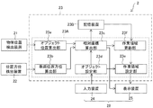
- the area setting support system 2 sets an object position detection device 21 that detects the position of an object around the work vehicle 5 and a work area of the work site by the work vehicle 5. It is provided with a setting device 23. Further, the area setting support system 2 includes an information terminal 28, and the information terminal 28 includes a display device 25 for displaying the position of the object detected by the object position detection device 21, and a plurality of display devices 25 displayed by the display device 25. It is provided with an input device 24 that selects a specific object from the objects of the above and inputs the selected object to the setting device. In the present embodiment, as will be described later, the position / orientation detection device 22 is mounted on the work vehicle 5 as an existing device.
- the information terminal 28 is a morphological touch panel display in which the display device 25 and the input device 24 are integrated.
- the display device 25 and the input device 24 may be provided separately, and for example, the information terminal 28 may have a built-in setting device 23.
- the setting device 23, the input device 24, and the display device 25 are arranged in the driver's cab 54, and when the setting device 23, the input device 24, and the display device 25 are individually provided, the setting device 23, the input device 24, and the display device 25 are provided separately. , These can communicate by wire or wirelessly, and if wireless, they may be connected via a network.
- the display device 25 and the input device 24 are provided inside the work vehicle 5 (driver's cab 54), but the setting device 23, the input device 24, and the display device 25 are provided outside the work vehicle 5. You may.
- the object position detection device 21 is a device that is arranged on the upper swivel body 52 and detects the position of an object (including an obstacle) in the work site around the work vehicle 5.
- the object position detecting device 21 is connected to the setting device 23 via a cable (not shown).
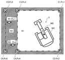
- the object position detecting device 21 detects the load cones C1 to C6 (movably installed area setting tools) and the workers M1 and M2 shown in FIG. 4 as an example of the object.
- the load cones C1 to C6 and the workers M1 and M2 may be collectively referred to as an object.
- the load cones C1 to C6 are for setting the work area R1 on which the work vehicle 5 works, and the other areas are non-workable areas (for example, a range through which the worker passes).
- the road cones C1 to C6 have the same shape and the same color, and these are not individually distinguished and may not have a solid identification tag or the like.
- the object position detecting device 21 detects these positions from the electromagnetic waves reflected by the load cones C1 to C6 and the workers M1 and M2, which are objects, for example, by transmitting electromagnetic waves. Specifically, the object position detection device 21 is based on the time from when the object position detection device 21 emits an electromagnetic wave until the electromagnetic wave is reflected by each object and received by the object position detection device 21. , Detects the distance from the object position detection device 21 to each object. Further, the object position detecting device 21 detects the direction (direction) of each object with respect to the object position detecting device 21 from the direction in which the reflected electromagnetic wave is received. In this way, the relative position of the object with respect to the work vehicle 5 can be specified more accurately. In the present embodiment, the object position detecting device 21 may identify the load cone and the operator so as to distinguish them from the intensity of the reflected electromagnetic wave and the like.
- the object position detecting device 21 detects the position and orientation of each object with respect to the work vehicle 5 by electromagnetic waves.
- the object position detecting device 21 is a stereo camera, and an image captured by the stereo camera. The position and orientation of each object may be detected based on.
- the object position detecting device 21 may detect the position and orientation of each object by using infrared rays.
- the object position detection device 21 may be, for example, an object position detection device 21 that is mounted on the work vehicle 5 in advance and detects an object around the work vehicle 5.
- the position / orientation detection device 22 is a device arranged on the upper swing body 52 as an existing device in the work vehicle 5, and is a device for detecting the position and direction of the work vehicle 5. is there.
- the position / orientation detection device 22 includes a pair of GNSS (Global Navigation Satellite System) antennas 22a and 22b. The pair of GNSS antennas 22a and 22b acquire the global coordinates of the respective GNSS antennas 22a and 22b.
- GNSS Global Navigation Satellite System
- the arithmetic unit 23A of the setting device 23, calculates the absolute position of the work vehicle 5 (vehicle body reference point position MC) and the absolute orientation of the work vehicle 5 (vehicle body orientation MD) from the global coordinates of the GNSS antennas 22a and 22b. get.
- the absolute position and absolute orientation of the work vehicle 5 are calculated by the arithmetic unit 23A.
- the position / orientation detection device 22 performs these calculations, and the position / orientation detection device 22 transfers the work vehicle to the arithmetic unit 23A.
- the absolute position and the absolute direction of 5 may be output.
- the vehicle body orientation MD corresponds to the traveling direction of the work vehicle 5.
- the absolute position of the work vehicle 5 and its absolute orientation are detected by a pair of GNSS antennas 22a and 22b.
- the absolute position is acquired by one GNSS antenna, and an inertial measurement unit (IMU) is attached to the work vehicle.
- the absolute orientation of the work vehicle 5 may be detected by the output from the inertial measurement unit, or the absolute orientation of the work vehicle 5 may be acquired by an angle detecting means such as a rotary encoder on the turning mechanism 52a or the like.
- the position / orientation detection device 22 is an existing device mounted on the work vehicle 5, but for example, the area setting support system 2 may be newly provided with the position / orientation detection device.
- the setting device 23 includes an arithmetic unit 23A and a storage device 23B.
- the arithmetic unit 23A includes an object position calculation unit 23a, a vehicle position / orientation calculation unit 23b, a relative coordinate calculation unit 23c, an object setting unit 23d, a work area setting unit 23e, and a work area update unit 23f.
- the object position calculation unit 23a calculates the position of the object around the work vehicle 5 based on the detection signal from the object position detection device 21.
- the calculated position of the object is a relative position from the work vehicle 5 (object position detecting device 21).
- the "relative position” referred to here is a position that does not take into account the direction of the work vehicle 5 (the position relative to the traveling direction of the work vehicle 5).
- the object position calculation unit 23a calculates the relative positions of the load cones C1 to C6 and the workers M1 and M2.
- the vehicle position / orientation calculation unit 23b uses the detection signals of the pair of GNSS antennas 22a and 22b acquired by the position / orientation detection device 22 described above to obtain the vehicle body reference point position (absolute position) MC and the vehicle body orientation (absolute orientation) of the work vehicle 5. MD is calculated.
- the relative coordinate calculation unit 23c uses the relative coordinates of each object with respect to the work vehicle 5 from the position of the object calculated by the object position calculation unit 23a and the vehicle body reference point position MC and the vehicle body orientation MD calculated by the vehicle position / orientation calculation unit 23b. Is calculated. Specifically, as shown in FIG. 4, the relative coordinates Pc1 to Pc6 (two-dimensional coordinates) of the road cones C1 to C6 and the relative coordinates Pm1 of the workers M1 and M2 with respect to the vehicle body reference point position MC and the vehicle body orientation MD. , Pm2 (two-dimensional coordinates) is calculated.
- the relative coordinate calculation unit 23c displays the calculated relative coordinates Pc1 to Pc6, Pm1 and Pm2 of the object on the display device 25 together with the vehicle body reference point position MC and the vehicle body orientation MD (see FIG. 4). As a result, the operator can grasp the position of the object with respect to the traveling direction of the work vehicle 5. Specifically, as shown in FIG. 5, the load cones C1 to C6 are displayed on the display screen 28a of the information terminal 28 by the icon Ic. In FIG.
- a bird's-eye view image of the work vehicle 5 and an icon image Ic corresponding to the relative coordinates Pc1 to Pc6 from the vehicle body reference point position MC of the work vehicle 5 are displayed on the display screen 28a of the information terminal 28 together with the bird's-eye view image.
- the icon image Ic may be displayed using the image of the omnidirectional camera mounted on the work vehicle 5 as the background image.
- the object setting unit 23d sets the work area R1 of the work vehicle 5 based on the position of the specific object input by the input device 24. Specifically, the operator selects a load cone for partitioning the work area R1 to be set from the objects displayed on the display device 25. Specifically, the operator selects and loads the load cones C1 to C4 by clicking the icon Ic corresponding to the load cones C1 to C4 displayed on the display screen 28a of the information terminal 28 shown in FIG. The identification information of the cones C1 to C4 is input to the setting device 23.
- the object is selected by the operator while collating the object displayed on the display device 25 with the actual object visually observed by the operator, but the confirmation of the object by the operator is displayed on, for example, an image pickup device. You may go from the image.
- the work area setting unit 23e sets the work area R1 on which the work vehicle 5 works, as shown in FIG. 4, based on the relative coordinates Pc1 to Pc4 of the load cones C1 to C4 set by the object setting unit 23d. Areas other than the work area R1 are set as non-work areas R2 that workers can pass through.
- the work area setting unit 23e connects each relative coordinate by a line segment (straight line) based on the relative coordinates Pc1 to Pc4 of the load cones C1 to C4, and the work area R1 surrounds these line segments.
- the work area R1 may be set so as to surround each relative coordinate with a predetermined function curve.
- a predetermined area for example, a rectangular or circular area
- a predetermined area including the work of these load cones is set as the work area R1. May be good.
- the relative coordinates of the object calculated by the relative coordinate calculation unit 23c change, and accordingly, the relative of the specific object set by the object setting unit 23d.
- the coordinates also change, and the relative position of the work area set by the work area setting unit 23e also changes. Further, when the operator changes the positions of the selected load cones C1 to C4, the same change occurs.
- the relative coordinate calculation unit 23c calculates the relative coordinates of the object at a predetermined interval (for example, a predetermined period), and the storage device 23B stores the calculated relative coordinates of the object.
- the work area update unit 23f is set by the object setting unit 23d from the relative coordinates of the object calculated by the relative coordinate calculation unit 23c and the relative coordinates of the object calculated one cycle before the relative coordinates and stored in the storage device 23B. Match the coordinates of each object.
- the work area update unit 23f reads out the relative coordinates of the object stored in the storage device 23B from the storage device 23B. Next, the work area update unit 23f compares the relative coordinates of the object newly calculated by the relative coordinate calculation unit 23c with the relative coordinates of the object read by the storage device 23B, and if they are different, these The relative coordinates of the object are collated, and the relative coordinates are updated to the newly calculated relative coordinates of the object. Since the relative coordinates of the load cones C1 to C4, which are specific objects, are also updated for setting the work area R1, the work area update unit 23f updates the position and range of the work area R1 based on the updated relative coordinates. To do. The work area setting unit 23e resets the work area R1 based on the updated position of the work area R1 and outputs the work area R1 to the display device 25.
- the relative coordinates of the object calculated by the relative coordinate calculation unit 23c may change due to the movement or turning of the work vehicle 5, but even in such a case, the relative coordinates of the changing object and the work area may change. Since the position and range of R1 are updated, the operator can accurately grasp the work area R1. Since the updated position and range of the work area R1 can be displayed on the display device 25 together with the work vehicle 5, the operator of the work vehicle 5 can work more comfortably in the work area R1 by the work vehicle 5. It can be carried out.
- the relative coordinate calculation unit 23c calculates the relative coordinates of the object at predetermined intervals, for example, even when the object moves, it is compared with the relative coordinates of the object read by the storage device 23B, and the object is compared with the relative coordinates of the object. Can determine which object read out.
- the work area update unit 23f can specify the moved load cones C1 to C4.
- the changing work area R1 can be updated.
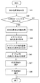
- FIG. 6 is a flow chart showing a method of setting the work area R1 by the setting device 23
- FIG. 7 is a flow chart showing a method of updating the work area R1 by the setting device 23. , The flow of the setting method of the work area R1 will be described.
- step S41 the setting device 23 acquires the detection signal of the position information of the object (object) from the object position detection device 21.
- step S42 the object position calculation unit 23a determines whether or not an arbitrary object has been detected.
- the object position calculation unit 23a does not detect the object (No)
- the work area R1 cannot be set, so the process ends without setting the work area R1 by the setting device 23. To do.
- the process proceeds to step S43.
- step S43 the vehicle position / orientation calculation unit 23b calculates the vehicle body reference point position MC and the vehicle body orientation MD using the absolute position information acquired from each of the pair of GNSS antennas 22a and 22b, and calculates the vehicle body orientation MD. Acquire and proceed to step S44.
- step S44 the relative coordinate calculation unit 23c calculates the relative coordinates of the detected arbitrary object using the vehicle body reference point position MC and the vehicle body direction MD, acquires the relative coordinates, and proceeds to step S45.
- step S45 the relative coordinate calculation unit 23c displays the relative coordinates of the object, the vehicle body reference point position MC of the work vehicle 5, and the vehicle body orientation MD on the display device 25 (specifically, the display screen 28a of the information terminal 28). .. Further, in this step, the relative coordinates of the acquired arbitrary object are stored in the storage device 23B, and the process proceeds to step S46.
- step S46 the identification information of specific objects (load cones C1 to C4) for setting the work area R1 is input to the setting device 23 via the input device 24 by selecting from the objects displayed by the display device 25. To do.
- the object setting unit 23d sets specific objects (load cones C1 to C4).
- the input of the identification information of the specific objects (load cones C1 to C4) is performed on the display screen 28a on the information terminal 28 having the functions of the input device 24 and the display device 25 shown in FIG. This is done by clicking the displayed road cones C1 to C4 icons.
- step S47 the work area setting unit 23e sets the work area R1 based on the relative coordinates Pc1 to Pc4 of the set specific objects (load cones C1 to C4), and sets the work area R1 as an information terminal. It is displayed on the display screen 28a of 28. In this way, the operator can recognize the traveling direction of the work vehicle 5 and the position of the work vehicle 5 with respect to the work area R1 from the display screen 28a, so that the work by the work vehicle 5 in the work area R1 can be recognized. Can be done properly.
- step S55 it is determined whether or not an undetected object has been recognized. In this determination, the relative coordinates of the object stored in the previous process are compared with the relative coordinates of the object acquired in step S54, and it is determined whether the object is an undetected object.
- step S56 the relative coordinates of the object are stored in the storage device 23B.
- step S56 the detected coordinate information Pc1 to Pc6 of the load cones C1 to C6 are stored in the storage device 23B.
- step S57 the work area update unit 23f is based on the relative coordinates of the object calculated by the relative coordinate calculation unit 23c and the relative coordinates of the object calculated one cycle before and stored in the storage device 23B.
- the relative coordinates of the load cones C1 to C4, which are specific objects, are updated, and the position and range of the work area R1 are updated based on the updated relative coordinates.
- step S58 the updated work area R1 is displayed on the display screen 28a of the information terminal 28.
- the work area information generated by the work area setting unit 23e and the work area update unit 23f which is composed of the work area boundary and the work area range, may be stored in the storage device 23B and can be read out at any time.
- the work vehicle 5 may limit the operation of the work vehicle 5 when the work vehicle 5 is removed from the work area R1 set by the setting device 23.
- the operation control device specifically, the engine control device
- the operation control device 67 reduces the rotation speed of the engine 65.
- the operating speed of the work vehicle 5 may be reduced.
- the operation control device 67 specifically, the valve control device
- the flow rate of the hydraulic oil to the control valve 63 that controls the traveling operation, the turning operation, and the front operation is reduced. Therefore, the operating speed of the work vehicle 5 may be reduced.
- the operation control device (specifically, the engine control device) 67 may stop the operation of the work vehicle 5 by stopping the engine 65, and performs the traveling operation, the turning operation, and the front operation.
- the operation of the work vehicle 5 may be stopped by shutting off the hydraulic oil to the control valve 63 to be controlled.
- the work vehicle 5 can ensure the safety of the worker passing through the non-work area R2 by limiting the operation of the work vehicle 5 when the work vehicle 5 is removed from the work area R1. it can.
- the area setting support system 2 can detect the no-entry area defined by any object at any time. In this way, the area setting support system 2 can appropriately assist the operator so that an arbitrary work area can be uniquely selected.
Landscapes
- Engineering & Computer Science (AREA)
- Mining & Mineral Resources (AREA)
- Civil Engineering (AREA)
- General Engineering & Computer Science (AREA)
- Structural Engineering (AREA)
- Multimedia (AREA)
- Signal Processing (AREA)
- Component Parts Of Construction Machinery (AREA)
- Operation Control Of Excavators (AREA)
- Closed-Circuit Television Systems (AREA)
Applications Claiming Priority (2)
| Application Number | Priority Date | Filing Date | Title |
|---|---|---|---|
| JP2019179120A JP7321047B2 (ja) | 2019-09-30 | 2019-09-30 | 作業車両 |
| JP2019-179120 | 2019-09-30 |
Publications (1)
| Publication Number | Publication Date |
|---|---|
| WO2021065814A1 true WO2021065814A1 (ja) | 2021-04-08 |
Family
ID=75270088
Family Applications (1)
| Application Number | Title | Priority Date | Filing Date |
|---|---|---|---|
| PCT/JP2020/036666 Ceased WO2021065814A1 (ja) | 2019-09-30 | 2020-09-28 | 領域設定支援システムおよびこれを搭載した作業車両 |
Country Status (2)
| Country | Link |
|---|---|
| JP (1) | JP7321047B2 (https=) |
| WO (1) | WO2021065814A1 (https=) |
Families Citing this family (2)
| Publication number | Priority date | Publication date | Assignee | Title |
|---|---|---|---|---|
| JP7809945B2 (ja) * | 2021-11-02 | 2026-02-03 | コベルコ建機株式会社 | 位置情報設定システム |
| JP7830781B2 (ja) * | 2022-03-31 | 2026-03-17 | 住友重機械工業株式会社 | 建設機械の作業支援システム |
Citations (3)
| Publication number | Priority date | Publication date | Assignee | Title |
|---|---|---|---|---|
| JP2009110304A (ja) * | 2007-10-30 | 2009-05-21 | Canon Inc | 画像処理装置、画像処理方法 |
| JP2013159930A (ja) * | 2012-02-02 | 2013-08-19 | Sumitomo Heavy Ind Ltd | 周囲監視装置 |
| WO2017061250A1 (ja) * | 2015-10-08 | 2017-04-13 | コニカミノルタ株式会社 | オブジェクト操作システム、オブジェクト操作制御プログラム及びオブジェクト操作制御方法 |
Family Cites Families (3)
| Publication number | Priority date | Publication date | Assignee | Title |
|---|---|---|---|---|
| JP4996928B2 (ja) * | 2007-01-05 | 2012-08-08 | 日立建機株式会社 | 作業機械の周囲監視装置 |
| JP2013009267A (ja) * | 2011-06-27 | 2013-01-10 | Kyushu Electric Power Co Inc | 周囲監視装置 |
| JP5755576B2 (ja) * | 2012-01-25 | 2015-07-29 | 住友重機械工業株式会社 | 運転補助装置 |
-
2019
- 2019-09-30 JP JP2019179120A patent/JP7321047B2/ja active Active
-
2020
- 2020-09-28 WO PCT/JP2020/036666 patent/WO2021065814A1/ja not_active Ceased
Patent Citations (3)
| Publication number | Priority date | Publication date | Assignee | Title |
|---|---|---|---|---|
| JP2009110304A (ja) * | 2007-10-30 | 2009-05-21 | Canon Inc | 画像処理装置、画像処理方法 |
| JP2013159930A (ja) * | 2012-02-02 | 2013-08-19 | Sumitomo Heavy Ind Ltd | 周囲監視装置 |
| WO2017061250A1 (ja) * | 2015-10-08 | 2017-04-13 | コニカミノルタ株式会社 | オブジェクト操作システム、オブジェクト操作制御プログラム及びオブジェクト操作制御方法 |
Also Published As
| Publication number | Publication date |
|---|---|
| JP2021055381A (ja) | 2021-04-08 |
| JP7321047B2 (ja) | 2023-08-04 |
Similar Documents
| Publication | Publication Date | Title |
|---|---|---|
| US12286769B2 (en) | Work machine and assist device to assist in work with work machine | |
| JP6987186B2 (ja) | 表示システム、建設機械、及び表示方法 | |
| CN114144555B (zh) | 挖土机及挖土机的显示装置 | |
| US9797247B1 (en) | Command for underground | |
| WO2020080538A1 (ja) | ショベル | |
| KR102659076B1 (ko) | 쇼벨 | |
| WO2020196874A1 (ja) | 建設機械、支援システム | |
| EP3998383A1 (en) | Operation instruction system | |
| EP3885495B1 (en) | Excavator and excavator control device | |
| JP7798253B2 (ja) | 作業機械、情報処理装置 | |
| CN114829710B (zh) | 挖土机、远程操作支援装置 | |
| EP3788205B1 (en) | System and method for selectively displaying image data in a working machine | |
| JP6823036B2 (ja) | 建設機械の表示システムおよびその制御方法 | |
| KR102769196B1 (ko) | 침입 감시 제어 시스템 및 작업 기계 | |
| WO2021065814A1 (ja) | 領域設定支援システムおよびこれを搭載した作業車両 | |
| JP2022179081A (ja) | 遠隔操作支援システム、遠隔操作支援装置 | |
| JP2021155937A (ja) | 施工支援システム | |
| AU2018201213B2 (en) | Command for underground | |
| JP2023074040A (ja) | 監視エリア設定システム | |
| JP2022182529A (ja) | 遠隔操作支援システム、遠隔操作支援装置 | |
| JP2021050602A (ja) | 建設機械の表示システムおよびその制御方法 | |
| JP2024005842A (ja) | 作業現場監視システム | |
| KR20140119911A (ko) | 센서를 이용한 굴삭기의 후방 확인장치 | |
| JP7843633B2 (ja) | 情報処理装置、情報処理システム及び情報処理プログラム | |
| CA3118562C (en) | A system and method for generating images based on work machine traveling state |
Legal Events
| Date | Code | Title | Description |
|---|---|---|---|
| 121 | Ep: the epo has been informed by wipo that ep was designated in this application |
Ref document number: 20873021 Country of ref document: EP Kind code of ref document: A1 |
|
| NENP | Non-entry into the national phase |
Ref country code: DE |
|
| 122 | Ep: pct application non-entry in european phase |
Ref document number: 20873021 Country of ref document: EP Kind code of ref document: A1 |