WO2021065814A1 - Area setting assistance system and work vehicle mounting same - Google Patents
Area setting assistance system and work vehicle mounting same Download PDFInfo
- Publication number
- WO2021065814A1 WO2021065814A1 PCT/JP2020/036666 JP2020036666W WO2021065814A1 WO 2021065814 A1 WO2021065814 A1 WO 2021065814A1 JP 2020036666 W JP2020036666 W JP 2020036666W WO 2021065814 A1 WO2021065814 A1 WO 2021065814A1
- Authority
- WO
- WIPO (PCT)
- Prior art keywords
- work
- work vehicle
- area
- work area
- setting
- Prior art date
Links
Images


Classifications
-
- E—FIXED CONSTRUCTIONS
- E02—HYDRAULIC ENGINEERING; FOUNDATIONS; SOIL SHIFTING
- E02F—DREDGING; SOIL-SHIFTING
- E02F9/00—Component parts of dredgers or soil-shifting machines, not restricted to one of the kinds covered by groups E02F3/00 - E02F7/00
- E02F9/20—Drives; Control devices
-
- E—FIXED CONSTRUCTIONS
- E02—HYDRAULIC ENGINEERING; FOUNDATIONS; SOIL SHIFTING
- E02F—DREDGING; SOIL-SHIFTING
- E02F9/00—Component parts of dredgers or soil-shifting machines, not restricted to one of the kinds covered by groups E02F3/00 - E02F7/00
- E02F9/26—Indicating devices
-
- H—ELECTRICITY
- H04—ELECTRIC COMMUNICATION TECHNIQUE
- H04N—PICTORIAL COMMUNICATION, e.g. TELEVISION
- H04N7/00—Television systems
- H04N7/18—Closed-circuit television [CCTV] systems, i.e. systems in which the video signal is not broadcast
Abstract
Provided is an area setting assistance system which can suitably set a work area, for example, in large scale work site or complicated work site, even when the work area in which a worker works is changed. The present invention is an area setting assistance system 2 provided with a setting device 23 which sets a work area R1 in work site by means of a work vehicle 5. The area setting assistance system 2 is provide with: an object position detection device 21 which detects the positions of objects within the work area; a display device 25 which displays the positions of the objects detected by the object position detection device 21; and an input device 24 which selects a specific object from among the objects displayed on the display device 25. The setting device 23 sets the work area R1 of the work vehicle 5 on the basis of the position of the specified object.
Description
作業車両による作業現場のうち作業領域を設定する領域設定支援システムおよびこれを搭載した作業車両に関する。
Regarding the area setting support system that sets the work area in the work site by the work vehicle and the work vehicle equipped with this.
従来から、油圧ショベルや移動式クレーン等の作業車両の作業領域への侵入物(作業者、他の車両等)を検知して、衝突を回避するよう該作業車両を制御する制御装置および手法が提案されている。
Conventionally, control devices and methods for detecting intruders (workers, other vehicles, etc.) in the work area of a work vehicle such as a hydraulic excavator or a mobile crane and controlling the work vehicle to avoid a collision have been used. Proposed.
たとえば、特許文献1には、作業車両の作業領域への侵入物を監視して作業車両の起動や停止を制御する制御装置が開示されている。この制御装置では、作業車両の周囲に侵入禁止領域を予め設定し、作業領域内に侵入した作業者などの侵入物が設定された侵入禁止領域内に入ったときに作業車両を停止させている。
For example, Patent Document 1 discloses a control device that monitors an intruder in a work area of a work vehicle and controls the start and stop of the work vehicle. In this control device, an intrusion prohibited area is set in advance around the work vehicle, and the work vehicle is stopped when an intruder such as a worker who has invaded the work area enters the set intrusion prohibited area. ..
しかしながら、特許文献1に示す技術では、特定の範囲の作業領域を、作業禁止領域として設定しているが、実際の作業現場では、作業車両による作業領域は、多様な形状が存在し、作業者の作業状況の変化に伴って、作業領域の形状も変化する。このため、特定の範囲を作業領域として設定したとしても、実際の作業車両の作業領域に対応できないことが想定される。
However, in the technique shown in Patent Document 1, a work area in a specific range is set as a work prohibited area, but in an actual work site, the work area by a work vehicle has various shapes, and an operator As the work situation changes, the shape of the work area also changes. Therefore, even if a specific range is set as the work area, it is assumed that it cannot correspond to the actual work area of the work vehicle.
このような点を考慮すると、作業車両に搭載される物体検知装置を用いて、例えば作業現場に配置されたロードコーン等のオブジェクトを検出し、オブジェクトの位置情報から作業領域を設定する手法も考えられる。しかしながら、大規模な作業現場や複雑化した作業現場では作業領域と無関係なロードコーンも配置されていることもあり、検出した各オブジェクトの位置情報から適切な作業領域を判別することは難しい。
Considering these points, a method of detecting an object such as a road cone placed at a work site using an object detection device mounted on a work vehicle and setting a work area from the position information of the object is also considered. Be done. However, in a large-scale work site or a complicated work site, a load cone unrelated to the work area may be arranged, and it is difficult to determine an appropriate work area from the position information of each detected object.
本発明は、このような点に鑑みてなされたものであり、その目的とするところは、例えば大規模な作業現場や複雑化した作業現場において、作業者が作業する作業領域が変化する場合であっても、その作業領域を適切に設定することができる領域設定支援システムを提供することにある。
The present invention has been made in view of these points, and an object of the present invention is, for example, when a work area in which a worker works changes in a large-scale work site or a complicated work site. Even if there is, the purpose is to provide an area setting support system that can appropriately set the work area.
前記課題を鑑みて、本発明に係る領域設定支援システムは、作業車両による作業現場のうち作業領域を設定する設定装置を備えた領域設定支援システムであって、前記領域設定支援システムは、作業現場内のオブジェクトの位置を検出する物体位置検出装置と、前記物体位置検出装置で検出されたオブジェクトの位置を表示する表示装置と、前記表示装置で表示されたオブジェクトの中から、特定のオブジェクトを選択する入力装置と、を備えており、前記設定装置は、前記特定のオブジェクトの位置に基づいて、前記作業車両の作業領域を設定することを特徴とする。
In view of the above problems, the area setting support system according to the present invention is an area setting support system including a setting device for setting a work area in a work site by a work vehicle, and the area setting support system is a work site. A specific object is selected from an object position detecting device that detects the position of an object in the object, a display device that displays the position of the object detected by the object position detecting device, and an object displayed by the display device. The setting device includes an input device for setting a work area of the work vehicle based on the position of the specific object.
本発明によれば、物体位置検出装置で検出したオブジェクトの位置を検出し、検出した位置を表示装置に表示することができる。表示装置で表示された複数のオブジェクトの中から、特定のオブジェクトを入力装置で選択入力することができる。これにより、特定のオブジェクトの位置に基づいて、作業車両の作業領域を設定することができるので、大規模な作業現場や複雑化した作業現場において、作業者が作業する作業領域が変化する場合であっても、その作業領域を適切に設定することができる。
According to the present invention, the position of the object detected by the object position detecting device can be detected, and the detected position can be displayed on the display device. A specific object can be selected and input by the input device from a plurality of objects displayed on the display device. As a result, the work area of the work vehicle can be set based on the position of a specific object, so that the work area in which the worker works changes in a large-scale work site or a complicated work site. Even if there is, the work area can be set appropriately.
図1~7を参照して、本発明の第1および第2実施形態に係る領域設定システム1を説明する。
The area setting system 1 according to the first and second embodiments of the present invention will be described with reference to FIGS. 1 to 7.
1.作業車両5について
まず、領域設定支援システム2が搭載された作業車両5を説明する。図1に示すように、作業車両5として、たとえば、油圧ショベルなどを挙げることができる。作業車両5は、クローラ式の下部走行体51と、下部走行体51上に、旋回機構52aを介して旋回可能に設けられた上部旋回体52と、上部旋回体52に取り付けられた多関節式のフロント作業機53とを備えている。 1. 1. About thework vehicle 5 First, the work vehicle 5 equipped with the area setting support system 2 will be described. As shown in FIG. 1, as the work vehicle 5, for example, a hydraulic excavator or the like can be mentioned. The work vehicle 5 is a crawler type lower traveling body 51, an upper swivel body 52 provided on the lower traveling body 51 so as to be swivelable via a swivel mechanism 52a, and an articulated type attached to the upper swivel body 52. It is equipped with a front working machine 53.
まず、領域設定支援システム2が搭載された作業車両5を説明する。図1に示すように、作業車両5として、たとえば、油圧ショベルなどを挙げることができる。作業車両5は、クローラ式の下部走行体51と、下部走行体51上に、旋回機構52aを介して旋回可能に設けられた上部旋回体52と、上部旋回体52に取り付けられた多関節式のフロント作業機53とを備えている。 1. 1. About the
下部走行体51の前端部にアイドラ51A1が設けられ、後端部に走行用油圧モータ61(図2参照)により駆動されるスプロケット51A2が設けられる。アイドラ51A1とスプロケット51A2とには、リンクアッセンブリ51Bが架け渡されており、アイドラ51A1とのスプロケット51A2の間には、リンクアッセンブリ51Bを案内するローラ51Cが設けられている。リンクアッセンブリ51Bには、地面に設置するシュープレート51Dが取り付けられている。下部走行体51のスプロケット51A2には、減速機等(図示せず)を介して走行用油圧モータ61(図2参照)が連結されている。走行用油圧モータ61の駆動により、下部走行体51のスプロケット51A2を回転させ、作業車両5が移動可能となる。
An idler 51A1 is provided at the front end of the lower traveling body 51, and a sprocket 51A2 driven by a traveling hydraulic motor 61 (see FIG. 2) is provided at the rear end. A link assembly 51B is bridged between the idler 51A1 and the sprocket 51A2, and a roller 51C for guiding the link assembly 51B is provided between the idler 51A1 and the sprocket 51A2. A shoe plate 51D to be installed on the ground is attached to the link assembly 51B. A traveling hydraulic motor 61 (see FIG. 2) is connected to the sprocket 51A2 of the lower traveling body 51 via a speed reducer or the like (not shown). By driving the traveling hydraulic motor 61, the sprocket 51A2 of the lower traveling body 51 is rotated, and the work vehicle 5 can be moved.
上部旋回体52の前方の左右一方側には運転室54が設けられ、上部旋回体52の前方の中央には上下方向に回動して掘削等の作業を行うべく、フロント作業機53が取り付けられている。運転室54の後方には、後述するエンジン65等の動力源が搭載された機関室58が設けられている。さらに、上部旋回体52の後部には機体の重量のバランスを保つカウンタウェイト56が設けられている。下部走行体51と上部旋回体52との間には、減速機等(図示せず)を介して、旋回用油圧モータ62(図2参照)が連結されている。旋回用油圧モータ62の駆動により、下部走行体51に対して、上部旋回体52を旋回させることができる。
A driver's cab 54 is provided on one of the left and right sides in front of the upper swivel body 52, and a front work machine 53 is attached to the center in front of the upper swivel body 52 so as to rotate in the vertical direction to perform work such as excavation. Has been done. Behind the driver's cab 54, an engine room 58 equipped with a power source such as an engine 65, which will be described later, is provided. Further, a counterweight 56 for maintaining the balance of the weight of the machine body is provided at the rear part of the upper swing body 52. A swivel hydraulic motor 62 (see FIG. 2) is connected between the lower traveling body 51 and the upper swivel body 52 via a speed reducer or the like (not shown). By driving the swivel hydraulic motor 62, the upper swivel body 52 can be swiveled with respect to the lower traveling body 51.
フロント作業機53は、上部旋回体52に枢動自在に取り付けられたブーム53Aと、ブーム53Aの先端に枢動自在に取り付けられたアーム53Bと、アーム53Bに枢動自在に取り付けられたバケット53Cと、を備えている。
The front work machine 53 includes a boom 53A pivotally attached to the upper swing body 52, an arm 53B pivotally attached to the tip of the boom 53A, and a bucket 53C pivotally attached to the arm 53B. And have.
ブーム53Aは、ブーム53Aと上部旋回体52との間に取り付けられた油圧式のブームシリンダ53aにより作動する。アーム53Bは、ブーム53Aとアーム53Bの間に取り付けられた油圧式のアームシリンダ53bにより作動する。バケット53Cは、アーム53Bとバケット53Cとの間に取り付けられた油圧式のバケットシリンダ53cにより作動する。以下、ブーム53A、アーム53B、およびバケット53Cの少なくとも1つの動作を、フロント作業機53の作業動作と称する。
The boom 53A is operated by a hydraulic boom cylinder 53a attached between the boom 53A and the upper swing body 52. The arm 53B is operated by a hydraulic arm cylinder 53b mounted between the boom 53A and the arm 53B. The bucket 53C is operated by a hydraulic bucket cylinder 53c attached between the arm 53B and the bucket 53C. Hereinafter, at least one operation of the boom 53A, the arm 53B, and the bucket 53C will be referred to as a work operation of the front work machine 53.
図2に示すように、本実施形態では、作業車両5は、エンジン65と、エンジン65に連結された作動ポンプ64と、作動ポンプ64に接続されたコントロールバルブ63と、をさらに備えている。作動ポンプ64は、エンジン65の出力により駆動し、オイルタンク(図示せず)から供給される作動油の圧力を昇圧する装置である。作動ポンプ64により昇圧された作動油がコントロールバルブ63に流れるように、作動ポンプ64は、コントロールバルブ63に接続されている。
As shown in FIG. 2, in the present embodiment, the work vehicle 5 further includes an engine 65, an operating pump 64 connected to the engine 65, and a control valve 63 connected to the operating pump 64. The actuating pump 64 is a device that is driven by the output of the engine 65 and boosts the pressure of hydraulic oil supplied from an oil tank (not shown). The working pump 64 is connected to the control valve 63 so that the hydraulic oil boosted by the working pump 64 flows to the control valve 63.
作動制御装置67は、コントロールバルブ63、作動ポンプ64、およびエンジン65に電気的に接続されている。コントロールバルブ63は、操作者による操作装置68の操作に起因した指令により、作動制御装置67を介して、下部走行体51の走行動作、上部旋回体52の旋回動作、およびフロント作業機53による作業動作に要する作動油(圧油)を分配し、これらの動作を制御する。
The operation control device 67 is electrically connected to the control valve 63, the operation pump 64, and the engine 65. In the control valve 63, the traveling operation of the lower traveling body 51, the turning operation of the upper rotating body 52, and the operation by the front working machine 53 are performed via the operation control device 67 by a command caused by the operation of the operating device 68 by the operator. The hydraulic oil (pressure oil) required for operation is distributed and these operations are controlled.
具体的には、作動制御装置67からの制御信号により、コントロールバルブ63の開閉のタイミング、および弁開度が制御される。また、作動制御装置67からの制御信号により、作動ポンプ64の作動油の吐出量が制御される。さらに、作動制御装置67からエンジン65への制御信号により、エンジン65の駆動開始および駆動停止、エンジン65の回転数が制御される。このようにして、作業車両5のアクチュエータである、ブームシリンダ53a、アームシリンダ53b、バケットシリンダ53c、走行用油圧モータ61、および旋回用油圧モータ62に対して、作動油の供給開始および供給停止と、作動油の供給流量とが制御される。
Specifically, the timing of opening and closing of the control valve 63 and the valve opening degree are controlled by the control signal from the operation control device 67. Further, the discharge amount of the hydraulic oil of the operation pump 64 is controlled by the control signal from the operation control device 67. Further, the operation start and stop of the engine 65 and the rotation speed of the engine 65 are controlled by the control signal from the operation control device 67 to the engine 65. In this way, the supply of hydraulic oil is started and stopped for the boom cylinder 53a, the arm cylinder 53b, the bucket cylinder 53c, the traveling hydraulic motor 61, and the turning hydraulic motor 62, which are the actuators of the work vehicle 5. , The supply flow rate of hydraulic oil is controlled.
なお、本実施形態では、操作装置68は、運転室54に配置されており、ゲートロックレバー69等を含むオペレータが操作する機器である。操作装置68による操作量に応じて、作動制御装置67が上述した制御信号を生成し、作業車両5を動作させることができる。なお、作動制御装置67は、たとえば入力装置(図示せず)から入力さらに制御プログラムに基づいて、作業車両5を自動制御することも可能である。
In the present embodiment, the operation device 68 is a device that is arranged in the driver's cab 54 and is operated by an operator including a gate lock lever 69 and the like. The operation control device 67 can generate the above-mentioned control signal to operate the work vehicle 5 according to the amount of operation by the operation device 68. The operation control device 67 can also automatically control the work vehicle 5 based on an input device (not shown) and a control program, for example.
2.領域設定支援システム2について
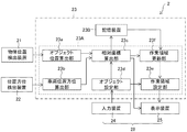
本実施形態では、領域設定支援システム2は、作業車両5の周りのオブジェクトの位置を検出する物体位置検出装置21と、作業現場のうち作業車両5による作業領域を設定する設定装置23とを備えている。さらに、領域設定支援システム2は、情報端末28を備えており、情報端末28は、物体位置検出装置21で検出されたオブジェクトの位置を表示する表示装置25と、表示装置25で表示された複数のオブジェクトの中から、特定のオブジェクトを選択し、選択したオブジェクトを設定装置に入力する入力装置24とを備えている。なお、本実施形態では、後述するように、位置方位検出装置22は、作業車両5に既存の装置として搭載されている。 2. About the area settingsupport system 2 In the present embodiment, the area setting support system 2 sets an object position detection device 21 that detects the position of an object around the work vehicle 5 and a work area of the work site by the work vehicle 5. It is provided with a setting device 23. Further, the area setting support system 2 includes an information terminal 28, and the information terminal 28 includes a display device 25 for displaying the position of the object detected by the object position detection device 21, and a plurality of display devices 25 displayed by the display device 25. It is provided with an input device 24 that selects a specific object from the objects of the above and inputs the selected object to the setting device. In the present embodiment, as will be described later, the position / orientation detection device 22 is mounted on the work vehicle 5 as an existing device.
本実施形態では、領域設定支援システム2は、作業車両5の周りのオブジェクトの位置を検出する物体位置検出装置21と、作業現場のうち作業車両5による作業領域を設定する設定装置23とを備えている。さらに、領域設定支援システム2は、情報端末28を備えており、情報端末28は、物体位置検出装置21で検出されたオブジェクトの位置を表示する表示装置25と、表示装置25で表示された複数のオブジェクトの中から、特定のオブジェクトを選択し、選択したオブジェクトを設定装置に入力する入力装置24とを備えている。なお、本実施形態では、後述するように、位置方位検出装置22は、作業車両5に既存の装置として搭載されている。 2. About the area setting
本実施形態では、情報端末28は、図5に示すように、表示装置25と入力装置24とが一体となった形態式のタッチパネルディスプレイである。しかしながら、たとえば、表示装置25と入力装置24とを個別に設けてもよく、たとえば、情報端末28に、設定装置23が内蔵されていてもよい。本実施形態では、設定装置23、入力装置24、および表示装置25は、運転室54に配置されており、設定装置23、入力装置24、および表示装置25が個別に設けられている場合には、これらは有線または無線により通信可能であり、無線である場合には、ネットワークを介して接続されていてもよい。なお、本実施形態では、表示装置25と入力装置24を作業車両5の内部(運転室54)に設けたが、設定装置23、入力装置24、および表示装置25を作業車両5の外部に設けてもよい。
In the present embodiment, as shown in FIG. 5, the information terminal 28 is a morphological touch panel display in which the display device 25 and the input device 24 are integrated. However, for example, the display device 25 and the input device 24 may be provided separately, and for example, the information terminal 28 may have a built-in setting device 23. In the present embodiment, the setting device 23, the input device 24, and the display device 25 are arranged in the driver's cab 54, and when the setting device 23, the input device 24, and the display device 25 are individually provided, the setting device 23, the input device 24, and the display device 25 are provided separately. , These can communicate by wire or wirelessly, and if wireless, they may be connected via a network. In the present embodiment, the display device 25 and the input device 24 are provided inside the work vehicle 5 (driver's cab 54), but the setting device 23, the input device 24, and the display device 25 are provided outside the work vehicle 5. You may.
2-1.物体位置検出装置21について
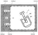
物体位置検出装置21は、上部旋回体52に配置され、作業車両5の周囲である作業現場内のオブジェクト(障害物も含む)の位置を検出する装置である。物体位置検出装置21は、ケーブル(図示せず)を介して、設定装置23に接続されている。本実施形態では、物体位置検出装置21は、オブジェクトの一例として、図4に示す、ロードコーンC1~C6(移動可能に設置する領域設定具)および作業者M1、M2を検出する。なお、以下の明細書では、ロードコーンC1~C6および作業者M1、M2をまとめて、オブジェクトということもある。ロードコーンC1~C6は、作業車両5が作業する作業領域R1を設定するためのものであり、それ以外の領域は、作業不可領域(例えば、作業者が通行する範囲)である。なお、ロードコーンC1~C6は、同じ形状および同じ色を有したものであり、これらは、個別に区別されるものではなく、固体識別タグなどを有しなくてもよい。 2-1. About the objectposition detection device 21 The object position detection device 21 is a device that is arranged on the upper swivel body 52 and detects the position of an object (including an obstacle) in the work site around the work vehicle 5. The object position detecting device 21 is connected to the setting device 23 via a cable (not shown). In the present embodiment, the object position detecting device 21 detects the load cones C1 to C6 (movably installed area setting tools) and the workers M1 and M2 shown in FIG. 4 as an example of the object. In the following specification, the load cones C1 to C6 and the workers M1 and M2 may be collectively referred to as an object. The load cones C1 to C6 are for setting the work area R1 on which the work vehicle 5 works, and the other areas are non-workable areas (for example, a range through which the worker passes). The road cones C1 to C6 have the same shape and the same color, and these are not individually distinguished and may not have a solid identification tag or the like.
物体位置検出装置21は、上部旋回体52に配置され、作業車両5の周囲である作業現場内のオブジェクト(障害物も含む)の位置を検出する装置である。物体位置検出装置21は、ケーブル(図示せず)を介して、設定装置23に接続されている。本実施形態では、物体位置検出装置21は、オブジェクトの一例として、図4に示す、ロードコーンC1~C6(移動可能に設置する領域設定具)および作業者M1、M2を検出する。なお、以下の明細書では、ロードコーンC1~C6および作業者M1、M2をまとめて、オブジェクトということもある。ロードコーンC1~C6は、作業車両5が作業する作業領域R1を設定するためのものであり、それ以外の領域は、作業不可領域(例えば、作業者が通行する範囲)である。なお、ロードコーンC1~C6は、同じ形状および同じ色を有したものであり、これらは、個別に区別されるものではなく、固体識別タグなどを有しなくてもよい。 2-1. About the object
物体位置検出装置21は、たとえば、電磁波を送信することにより、オブジェクトであるロードコーンC1~C6および作業者M1、M2に反射した電磁波から、これらの位置を検出するものである。具体的には、物体位置検出装置21は、物体位置検出装置21から電磁波を発信してから、この電磁波が、各オブジェクトに反射して物体位置検出装置21で受信されるまでの時間に基づいて、物体位置検出装置21から各オブジェクトまでの距離を検出する。さらに、物体位置検出装置21は、反射した電磁波を受信した方向から、物体位置検出装置21に対する各オブジェクトの方向(方位)を検出する。このようにして、作業車両5に対するオブジェクトの相対位置をより正確に特定することができる。本実施形態では、物体位置検出装置21は、反射した電磁波の強さ等から、ロードコーンと作業者とを区別するように、識別してもよい。
The object position detecting device 21 detects these positions from the electromagnetic waves reflected by the load cones C1 to C6 and the workers M1 and M2, which are objects, for example, by transmitting electromagnetic waves. Specifically, the object position detection device 21 is based on the time from when the object position detection device 21 emits an electromagnetic wave until the electromagnetic wave is reflected by each object and received by the object position detection device 21. , Detects the distance from the object position detection device 21 to each object. Further, the object position detecting device 21 detects the direction (direction) of each object with respect to the object position detecting device 21 from the direction in which the reflected electromagnetic wave is received. In this way, the relative position of the object with respect to the work vehicle 5 can be specified more accurately. In the present embodiment, the object position detecting device 21 may identify the load cone and the operator so as to distinguish them from the intensity of the reflected electromagnetic wave and the like.
本実施形態では、物体位置検出装置21は、電磁波により、作業車両5に対する各オブジェクトの位置および方位を検出するが、例えば、物体位置検出装置21がステレオカメラであり、このステレオカメラで撮像した画像に基づいて、各オブジェクトの位置および方位を検出してもよい。この他にも、物体位置検出装置21は、赤外線を利用して各オブジェクトの位置および方位を検出してもよい。なお、物体位置検出装置21は、たとえば、作業車両5に予め搭載され、作業車両5の周りの物体を検出する物体位置検出装置21であってもよい。
In the present embodiment, the object position detecting device 21 detects the position and orientation of each object with respect to the work vehicle 5 by electromagnetic waves. For example, the object position detecting device 21 is a stereo camera, and an image captured by the stereo camera. The position and orientation of each object may be detected based on. In addition to this, the object position detecting device 21 may detect the position and orientation of each object by using infrared rays. The object position detection device 21 may be, for example, an object position detection device 21 that is mounted on the work vehicle 5 in advance and detects an object around the work vehicle 5.
2-2.位置方位検出装置22について
本実施形態では、位置方位検出装置22は、作業車両5に既存の装置として上部旋回体52に配置された装置であり、作業車両5の位置と方位を検出する装置である。本実施形態では、位置方位検出装置22は、一対のGNSS(Global Navigation Satellite System)アンテナ22a、22bを備えている。一対のGNSSアンテナ22a、22bにより、各GNSSアンテナ22a、22bのグローバル座標を取得する。後述する設定装置23の演算装置23Aは、各GNSSアンテナ22a、22bのグローバル座標から作業車両5の絶対位置(車体基準点位置MC)と作業車両5(車体方位MD)の絶対方位を算出し、取得する。なお、作業車両5の絶対位置と絶対方位との算出は、演算装置23Aで行うが、例えば、位置方位検出装置22でこれらの算出を行い、位置方位検出装置22から演算装置23Aに、作業車両5の絶対位置と絶対方位とを出力してもよい。本実施形態では、車体方位MDは、作業車両5の進行方向に相当する。 2-2. Position /Direction Detection Device 22 In the present embodiment, the position / orientation detection device 22 is a device arranged on the upper swing body 52 as an existing device in the work vehicle 5, and is a device for detecting the position and direction of the work vehicle 5. is there. In the present embodiment, the position / orientation detection device 22 includes a pair of GNSS (Global Navigation Satellite System) antennas 22a and 22b. The pair of GNSS antennas 22a and 22b acquire the global coordinates of the respective GNSS antennas 22a and 22b. The arithmetic unit 23A of the setting device 23, which will be described later, calculates the absolute position of the work vehicle 5 (vehicle body reference point position MC) and the absolute orientation of the work vehicle 5 (vehicle body orientation MD) from the global coordinates of the GNSS antennas 22a and 22b. get. The absolute position and absolute orientation of the work vehicle 5 are calculated by the arithmetic unit 23A. For example, the position / orientation detection device 22 performs these calculations, and the position / orientation detection device 22 transfers the work vehicle to the arithmetic unit 23A. The absolute position and the absolute direction of 5 may be output. In the present embodiment, the vehicle body orientation MD corresponds to the traveling direction of the work vehicle 5.
本実施形態では、位置方位検出装置22は、作業車両5に既存の装置として上部旋回体52に配置された装置であり、作業車両5の位置と方位を検出する装置である。本実施形態では、位置方位検出装置22は、一対のGNSS(Global Navigation Satellite System)アンテナ22a、22bを備えている。一対のGNSSアンテナ22a、22bにより、各GNSSアンテナ22a、22bのグローバル座標を取得する。後述する設定装置23の演算装置23Aは、各GNSSアンテナ22a、22bのグローバル座標から作業車両5の絶対位置(車体基準点位置MC)と作業車両5(車体方位MD)の絶対方位を算出し、取得する。なお、作業車両5の絶対位置と絶対方位との算出は、演算装置23Aで行うが、例えば、位置方位検出装置22でこれらの算出を行い、位置方位検出装置22から演算装置23Aに、作業車両5の絶対位置と絶対方位とを出力してもよい。本実施形態では、車体方位MDは、作業車両5の進行方向に相当する。 2-2. Position /
本実施形態では、一対のGNSSアンテナ22a、22bにより作業車両5の絶対位置とその絶対方位を検出したが、例えばひとつのGNSSアンテナにより絶対位置を取得し、作業車両に慣性計測装置(IMU)を搭載し、慣性計測装置からの出力により、作業車両5の絶対方位を検出してもよく、旋回機構52a等にロータリーエンコーダ等の角度検出手段により作業車両5の絶対方位を取得してもよい。
In the present embodiment, the absolute position of the work vehicle 5 and its absolute orientation are detected by a pair of GNSS antennas 22a and 22b. For example, the absolute position is acquired by one GNSS antenna, and an inertial measurement unit (IMU) is attached to the work vehicle. The absolute orientation of the work vehicle 5 may be detected by the output from the inertial measurement unit, or the absolute orientation of the work vehicle 5 may be acquired by an angle detecting means such as a rotary encoder on the turning mechanism 52a or the like.
なお、本実施形態では、位置方位検出装置22は、作業車両5に搭載された既存の装置であるが、たとえば、領域設定支援システム2に、新たに位置方位検出装置を設けてもよい。
In the present embodiment, the position / orientation detection device 22 is an existing device mounted on the work vehicle 5, but for example, the area setting support system 2 may be newly provided with the position / orientation detection device.
2-3.設定装置23について
図3に示すように、設定装置23は、演算装置23Aと、記憶装置23Bとを備えている。演算装置23Aは、オブジェクト位置算出部23a、車両位置方位算出部23b、相対座標算出部23c、オブジェクト設定部23d、作業領域設定部23e、および作業領域更新部23fを備えている。 2-3. About thesetting device 23 As shown in FIG. 3, the setting device 23 includes an arithmetic unit 23A and a storage device 23B. The arithmetic unit 23A includes an object position calculation unit 23a, a vehicle position / orientation calculation unit 23b, a relative coordinate calculation unit 23c, an object setting unit 23d, a work area setting unit 23e, and a work area update unit 23f.
図3に示すように、設定装置23は、演算装置23Aと、記憶装置23Bとを備えている。演算装置23Aは、オブジェクト位置算出部23a、車両位置方位算出部23b、相対座標算出部23c、オブジェクト設定部23d、作業領域設定部23e、および作業領域更新部23fを備えている。 2-3. About the
オブジェクト位置算出部23aは、物体位置検出装置21からの検出信号に基づいて、作業車両5の周りのオブジェクトの位置を算出する。ここで、算出されるオブジェクトの位置は、作業車両5(物体位置検出装置21)からの相対的な位置である。ここでいう「相対的な位置」とは、作業車両5の方位(作業車両5の進行方向に対する相対的な位置)を加味していない位置のことである。本実施形態では、図4に示すように、オブジェクト位置算出部23aは、ロードコーンC1~C6および作業者M1、M2の相対的な位置を算出する。
The object position calculation unit 23a calculates the position of the object around the work vehicle 5 based on the detection signal from the object position detection device 21. Here, the calculated position of the object is a relative position from the work vehicle 5 (object position detecting device 21). The "relative position" referred to here is a position that does not take into account the direction of the work vehicle 5 (the position relative to the traveling direction of the work vehicle 5). In the present embodiment, as shown in FIG. 4, the object position calculation unit 23a calculates the relative positions of the load cones C1 to C6 and the workers M1 and M2.
車両位置方位算出部23bは、上述した位置方位検出装置22で取得した一対のGNSSアンテナ22a、22bの検出信号から、作業車両5の車体基準点位置(絶対位置)MCと車体方位(絶対方位)MDとを算出する。
The vehicle position / orientation calculation unit 23b uses the detection signals of the pair of GNSS antennas 22a and 22b acquired by the position / orientation detection device 22 described above to obtain the vehicle body reference point position (absolute position) MC and the vehicle body orientation (absolute orientation) of the work vehicle 5. MD is calculated.
相対座標算出部23cは、オブジェクト位置算出部23aで算出したオブジェクトの位置と、車両位置方位算出部23bで算出した車体基準点位置MC及び車体方位MDとから、作業車両5に対する各オブジェクトの相対座標を算出する。具体的には、図4に示すように、車体基準点位置MC及び車体方位MDに対する、ロードコーンC1~C6の相対座標Pc1~Pc6(2次元座標)、および作業者M1、M2の相対座標Pm1、Pm2(2次元座標)を算出する。
The relative coordinate calculation unit 23c uses the relative coordinates of each object with respect to the work vehicle 5 from the position of the object calculated by the object position calculation unit 23a and the vehicle body reference point position MC and the vehicle body orientation MD calculated by the vehicle position / orientation calculation unit 23b. Is calculated. Specifically, as shown in FIG. 4, the relative coordinates Pc1 to Pc6 (two-dimensional coordinates) of the road cones C1 to C6 and the relative coordinates Pm1 of the workers M1 and M2 with respect to the vehicle body reference point position MC and the vehicle body orientation MD. , Pm2 (two-dimensional coordinates) is calculated.
相対座標算出部23cは、算出したオブジェクトの相対座標Pc1~Pc6、Pm1、Pm2を、車体基準点位置MCおよび車体方位MDとともに、表示装置25に表示させる(図4参照)。これにより、作業車両5の進行方向に対して、オブジェクトがどの位置にあるかを操作者は把握することができる。具体的には、ロードコーンC1~C6は、図5に示すように、アイコンIcにより、情報端末28の表示画面28aに表示される。なお、図5では、情報端末28の表示画面28aには作業車両5の俯瞰画像と、作業車両5の車体基準点位置MC等から、相対座標Pc1~Pc6に対応したアイコン画像Icを俯瞰画像とともに表示したが、たとえば、作業車両5に搭載した全周囲カメラの画像を背景画像として、アイコン画像Icを表示してもよい。
The relative coordinate calculation unit 23c displays the calculated relative coordinates Pc1 to Pc6, Pm1 and Pm2 of the object on the display device 25 together with the vehicle body reference point position MC and the vehicle body orientation MD (see FIG. 4). As a result, the operator can grasp the position of the object with respect to the traveling direction of the work vehicle 5. Specifically, as shown in FIG. 5, the load cones C1 to C6 are displayed on the display screen 28a of the information terminal 28 by the icon Ic. In FIG. 5, a bird's-eye view image of the work vehicle 5 and an icon image Ic corresponding to the relative coordinates Pc1 to Pc6 from the vehicle body reference point position MC of the work vehicle 5 are displayed on the display screen 28a of the information terminal 28 together with the bird's-eye view image. Although it is displayed, for example, the icon image Ic may be displayed using the image of the omnidirectional camera mounted on the work vehicle 5 as the background image.
オブジェクト設定部23dは、入力装置24で入力された特定のオブジェクトの位置に基づいて、作業車両5の作業領域R1を設定する。具体的には、操作者が、表示装置25で表示されたオブジェクトから、設定すべき作業領域R1を区画するロードコーンを選択する。具体的には、操作者が、図5に示す情報端末28の表示画面28aに表示されたロードコーンC1~C4に該当するアイコンIcをクリックすることで、ロードコーンC1~C4を選択し、ロードコーンC1~C4の識別情報を設定装置23に入力する。なお、操作者によるオブジェクトの選択は、表示装置25に表示されたオブジェクトと、操作者が目視した実際のオブジェクトとを照合しながら行うが、操作者によるオブジェクトの確認を、たとえば撮像装置で表示された画像から行ってもよい。
The object setting unit 23d sets the work area R1 of the work vehicle 5 based on the position of the specific object input by the input device 24. Specifically, the operator selects a load cone for partitioning the work area R1 to be set from the objects displayed on the display device 25. Specifically, the operator selects and loads the load cones C1 to C4 by clicking the icon Ic corresponding to the load cones C1 to C4 displayed on the display screen 28a of the information terminal 28 shown in FIG. The identification information of the cones C1 to C4 is input to the setting device 23. The object is selected by the operator while collating the object displayed on the display device 25 with the actual object visually observed by the operator, but the confirmation of the object by the operator is displayed on, for example, an image pickup device. You may go from the image.
作業領域設定部23eは、オブジェクト設定部23dで設定したロードコーンC1~C4の相対座標Pc1~Pc4に基づいて、図4に示すように、作業車両5が作業する作業領域R1を設定する。作業領域R1以外の領域は、作業者が通行可能な非作業領域R2として設定される。
The work area setting unit 23e sets the work area R1 on which the work vehicle 5 works, as shown in FIG. 4, based on the relative coordinates Pc1 to Pc4 of the load cones C1 to C4 set by the object setting unit 23d. Areas other than the work area R1 are set as non-work areas R2 that workers can pass through.
本実施形態では、作業領域設定部23eは、ロードコーンC1~C4の相対座標Pc1~Pc4に基づいて、各相対座標を線分(直線)結んで、これらの線分を囲うように作業領域R1を設定する。この他にも、各相対座標を所定の関数曲線で囲うように作業領域R1を設定してもよい。また、たとえば入力装置24に1つまたは2つのロードコーンの識別情報を入力した場合、これらのロードコーンの作業を含む所定の領域(例えば、矩形、円形の領域)を作業領域R1として設定してもよい。
In the present embodiment, the work area setting unit 23e connects each relative coordinate by a line segment (straight line) based on the relative coordinates Pc1 to Pc4 of the load cones C1 to C4, and the work area R1 surrounds these line segments. To set. In addition to this, the work area R1 may be set so as to surround each relative coordinate with a predetermined function curve. Further, for example, when the identification information of one or two traffic cones is input to the input device 24, a predetermined area (for example, a rectangular or circular area) including the work of these load cones is set as the work area R1. May be good.
ここで、作業車両5が、移動したり、旋回したりすると、相対座標算出部23cで算出したオブジェクトの相対座標が変化し、これに伴い、オブジェクト設定部23dにより設定された特定のオブジェクトの相対座標も変化し、作業領域設定部23eで設定した作業領域の相対位置も変化してしまう。さらに、選択したロードコーンC1~C4の位置を、作業者が変更した場合も同様の変化が生じる。
Here, when the work vehicle 5 moves or turns, the relative coordinates of the object calculated by the relative coordinate calculation unit 23c change, and accordingly, the relative of the specific object set by the object setting unit 23d. The coordinates also change, and the relative position of the work area set by the work area setting unit 23e also changes. Further, when the operator changes the positions of the selected load cones C1 to C4, the same change occurs.
そこで、相対座標算出部23cは、オブジェクトの相対座標を所定の間隔(たとえば所定の周期)で算出し、記憶装置23Bは、この算出したオブジェクトの相対座標を記憶する。作業領域更新部23fは、相対座標算出部23cで算出したオブジェクトの相対座標と、その1周期前に算出され、記憶装置23Bで記憶されたオブジェクトの相対座標とから、オブジェクト設定部23dで設定された各オブジェクトの座標を照合する。
Therefore, the relative coordinate calculation unit 23c calculates the relative coordinates of the object at a predetermined interval (for example, a predetermined period), and the storage device 23B stores the calculated relative coordinates of the object. The work area update unit 23f is set by the object setting unit 23d from the relative coordinates of the object calculated by the relative coordinate calculation unit 23c and the relative coordinates of the object calculated one cycle before the relative coordinates and stored in the storage device 23B. Match the coordinates of each object.
具体的には、本実施形態では、作業領域更新部23fは、記憶装置23Bで記憶されたオブジェクトの相対座標を記憶装置23Bから読み出す。次に、作業領域更新部23fは、相対座標算出部23cで新たに算出したオブジェクトの相対座標と、記憶装置23Bで読み出したオブジェクトの相対座標を対比し、これらが相違する場合には、これらのオブジェクトの相対座標を照合するとともに、新たに算出したオブジェクトの相対座標に、相対座標を更新する。作業領域R1の設定のために特定のオブジェクトであるロードコーンC1~C4の相対座標も更新されるので、作業領域更新部23fは、更新した相対座標に基づき、作業領域R1の位置および範囲を更新する。作業領域設定部23eは、この更新された作業領域R1の位置に基づいて、作業領域R1を再設定し、表示装置25に出力する。
Specifically, in the present embodiment, the work area update unit 23f reads out the relative coordinates of the object stored in the storage device 23B from the storage device 23B. Next, the work area update unit 23f compares the relative coordinates of the object newly calculated by the relative coordinate calculation unit 23c with the relative coordinates of the object read by the storage device 23B, and if they are different, these The relative coordinates of the object are collated, and the relative coordinates are updated to the newly calculated relative coordinates of the object. Since the relative coordinates of the load cones C1 to C4, which are specific objects, are also updated for setting the work area R1, the work area update unit 23f updates the position and range of the work area R1 based on the updated relative coordinates. To do. The work area setting unit 23e resets the work area R1 based on the updated position of the work area R1 and outputs the work area R1 to the display device 25.
これにより、作業車両5の移動または旋回により、相対座標算出部23cで算出したオブジェクトの相対座標が変化することがあるが、このような場合であっても、変化するオブジェクトの相対座標と作業領域R1の位置および範囲を更新するので、操作者は、作業領域R1を正確に捉えることができる。更新された作業領域R1の位置および範囲は、作業車両5とともに表示装置25に表示することができるので、作業車両5の操作者は、作業車両5による作業領域R1内での作業をより安心して行うことができる。
As a result, the relative coordinates of the object calculated by the relative coordinate calculation unit 23c may change due to the movement or turning of the work vehicle 5, but even in such a case, the relative coordinates of the changing object and the work area may change. Since the position and range of R1 are updated, the operator can accurately grasp the work area R1. Since the updated position and range of the work area R1 can be displayed on the display device 25 together with the work vehicle 5, the operator of the work vehicle 5 can work more comfortably in the work area R1 by the work vehicle 5. It can be carried out.
さらに、相対座標算出部23cが、オブジェクトの相対座標を所定の間隔で算出するので、たとえば、オブジェクトが移動した場合であっても、記憶装置23Bで読み出したオブジェクトの相対座標と対比し、そのオブジェクトが、読み出したどのオブジェクトに対応するかを判定することができる。これにより、たとえば、領域R1を設定するロードコーンC1~C4が移動することにより作業領域R1の範囲が変化しても、作業領域更新部23fが、移動したロードコーンC1~C4を特定することができ、変化する作業領域R1を更新することができる。
Further, since the relative coordinate calculation unit 23c calculates the relative coordinates of the object at predetermined intervals, for example, even when the object moves, it is compared with the relative coordinates of the object read by the storage device 23B, and the object is compared with the relative coordinates of the object. Can determine which object read out. As a result, for example, even if the range of the work area R1 changes due to the movement of the load cones C1 to C4 for setting the area R1, the work area update unit 23f can specify the moved load cones C1 to C4. The changing work area R1 can be updated.
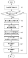
図6は、設定装置23による作業領域R1の設定方法を示すフロー図であり、図7は、設定装置23により作業領域R1の更新方法を示すフロー図であり、まず、図6を参照しながら、作業領域R1の設定方法のフローを説明する。
FIG. 6 is a flow chart showing a method of setting the work area R1 by the setting device 23, and FIG. 7 is a flow chart showing a method of updating the work area R1 by the setting device 23. , The flow of the setting method of the work area R1 will be described.
まず、ステップS41では、設定装置23は、物体位置検出装置21からのオブジェクト(物体)の位置情報の検出信号を取得する。次に、ステップS42において、オブジェクト位置算出部23aが、任意のオブジェクトを検出したかの判定を行う。ここで、オブジェクト位置算出部23aが、オブジェクトを検出していない場合(Noの場合)には、作業領域R1を設定することができないので、設定装置23による作業領域R1の設定を行わずに終了する。一方、オブジェクトを検出した場合(Yesの場合)には、ステップS43に進む。
First, in step S41, the setting device 23 acquires the detection signal of the position information of the object (object) from the object position detection device 21. Next, in step S42, the object position calculation unit 23a determines whether or not an arbitrary object has been detected. Here, if the object position calculation unit 23a does not detect the object (No), the work area R1 cannot be set, so the process ends without setting the work area R1 by the setting device 23. To do. On the other hand, when the object is detected (Yes), the process proceeds to step S43.
次に、ステップS43では、車両位置方位算出部23bは、一対のGNSSアンテナ22a、22bのそれぞれから取得する絶対位置の情報を用いて、車体基準点位置MCと車体方位MDを算出し、これを取得し、ステップS44に進む。
Next, in step S43, the vehicle position / orientation calculation unit 23b calculates the vehicle body reference point position MC and the vehicle body orientation MD using the absolute position information acquired from each of the pair of GNSS antennas 22a and 22b, and calculates the vehicle body orientation MD. Acquire and proceed to step S44.
ステップS44では、相対座標算出部23cは、車体基準点位置MCと車体方位MDを用いて、検知された任意のオブジェクトの相対座標を算出し、これを取得し、ステップS45に進む。
In step S44, the relative coordinate calculation unit 23c calculates the relative coordinates of the detected arbitrary object using the vehicle body reference point position MC and the vehicle body direction MD, acquires the relative coordinates, and proceeds to step S45.
ステップS45では、相対座標算出部23cは、オブジェクトの相対座標と、作業車両5の車体基準点位置MCおよび車体方位MDを表示装置25(具体的には情報端末28の表示画面28a)に表示させる。さらに、このステップでは、取得した任意のオブジェクトの相対座標を記憶装置23Bに記憶し、ステップS46に進む。
In step S45, the relative coordinate calculation unit 23c displays the relative coordinates of the object, the vehicle body reference point position MC of the work vehicle 5, and the vehicle body orientation MD on the display device 25 (specifically, the display screen 28a of the information terminal 28). .. Further, in this step, the relative coordinates of the acquired arbitrary object are stored in the storage device 23B, and the process proceeds to step S46.
ステップS46では、表示装置25で表示したオブジェクトから選択して、作業領域R1を設定するための特定のオブジェクト(ロードコーンC1~C4)の識別情報を、入力装置24を介して設定装置23に入力する。これにより、オブジェクト設定部23dは、特定のオブジェクト(ロードコーンC1~C4)を設定する。なお、本実施形態では、特定のオブジェクト(ロードコーンC1~C4)の識別情報の入力を、図5に示す入力装置24と表示装置25との機能を兼ね備えた情報端末28において、表示画面28aに表示されたロードコーンC1~C4のアイコンをクリックすることにより行う。
In step S46, the identification information of specific objects (load cones C1 to C4) for setting the work area R1 is input to the setting device 23 via the input device 24 by selecting from the objects displayed by the display device 25. To do. As a result, the object setting unit 23d sets specific objects (load cones C1 to C4). In the present embodiment, the input of the identification information of the specific objects (load cones C1 to C4) is performed on the display screen 28a on the information terminal 28 having the functions of the input device 24 and the display device 25 shown in FIG. This is done by clicking the displayed road cones C1 to C4 icons.
次に、ステップS47では、設定された特定のオブジェクト(ロードコーンC1~C4)の相対座標Pc1~Pc4に基づいて、作業領域設定部23eは、作業領域R1を設定し、作業領域R1を情報端末28の表示画面28aに表示する。このようにして、操作者は、表示画面28aから、作業車両5の進行方向と、作業領域R1に対する作業車両5の位置とを認識することができるため、作業領域R1内における作業車両5による作業を適切に行うことができる。
Next, in step S47, the work area setting unit 23e sets the work area R1 based on the relative coordinates Pc1 to Pc4 of the set specific objects (load cones C1 to C4), and sets the work area R1 as an information terminal. It is displayed on the display screen 28a of 28. In this way, the operator can recognize the traveling direction of the work vehicle 5 and the position of the work vehicle 5 with respect to the work area R1 from the display screen 28a, so that the work by the work vehicle 5 in the work area R1 can be recognized. Can be done properly.
次に、図7を参照し、設定装置23による作業領域R1の更新のフローを説明する。ステップS51からステップS54までは、図6のステップS41からステップS44までと同じであるため、その詳細な説明は省略する。ステップS55では、未検知のオブジェクトを認識したかを判定する。この判定では、前回の処理で記憶したオブジェクトの相対座標と、ステップS54で取得したオブジェクトの相対座標とを比較し、オブジェクトが未検知のオブジェクトであるかを判定する。
Next, with reference to FIG. 7, the flow of updating the work area R1 by the setting device 23 will be described. Since steps S51 to S54 are the same as steps S41 to S44 in FIG. 6, detailed description thereof will be omitted. In step S55, it is determined whether or not an undetected object has been recognized. In this determination, the relative coordinates of the object stored in the previous process are compared with the relative coordinates of the object acquired in step S54, and it is determined whether the object is an undetected object.
ここで、未検知のオブジェクトを認識していない場合(Noの場合)には、オブジェクトの相対座標に変化がなく、作業領域R1を更新する必要がないので、処理を終了する。一方、未検知のオブジェクトを認識した場合(Yesの場合)には、オブジェクトの相対座標は変化していると判断できるので、ステップS56に進む。
Here, when the undetected object is not recognized (No), the relative coordinates of the object do not change and it is not necessary to update the work area R1, so the process ends. On the other hand, when the undetected object is recognized (in the case of Yes), it can be determined that the relative coordinates of the object have changed, so the process proceeds to step S56.
ステップS56では、オブジェクトの相対座標を記憶装置23Bに記憶する。なお、このステップS56では、検出されたロードコーンC1~C6のそれぞれの座標情報Pc1~Pc6を記憶装置23Bに記憶する。
In step S56, the relative coordinates of the object are stored in the storage device 23B. In this step S56, the detected coordinate information Pc1 to Pc6 of the load cones C1 to C6 are stored in the storage device 23B.
次に、ステップS57では、作業領域更新部23fは、相対座標算出部23cで算出したオブジェクトの相対座標と、その1周期前に算出され、記憶装置23Bで記憶されたオブジェクトの相対座標とから、特定のオブジェクトであるロードコーンC1~C4の相対座標を更新し、更新した相対座標に基づき、作業領域R1の位置および範囲を更新する。最後に、ステップS58で、更新した作業領域R1を情報端末28の表示画面28aに表示する。
Next, in step S57, the work area update unit 23f is based on the relative coordinates of the object calculated by the relative coordinate calculation unit 23c and the relative coordinates of the object calculated one cycle before and stored in the storage device 23B. The relative coordinates of the load cones C1 to C4, which are specific objects, are updated, and the position and range of the work area R1 are updated based on the updated relative coordinates. Finally, in step S58, the updated work area R1 is displayed on the display screen 28a of the information terminal 28.
なお、作業領域設定部23eおよび作業領域更新部23fで生成された、業領域境界、および作業領域範囲によって構成される作業領域情報を、記憶装置23Bに記憶し、随時読み出し可能にしてもよい。
The work area information generated by the work area setting unit 23e and the work area update unit 23f, which is composed of the work area boundary and the work area range, may be stored in the storage device 23B and can be read out at any time.
ここで、作業車両5は、設定装置23で設定された作業領域R1から作業車両5が外れた際に、作業車両5の動作を制限してもよい。具体的には、設定装置23により設定した作業領域R1から作業車両5が外れた際には、作動制御装置(具体的にはエンジン制御装置)67が、エンジン65の回転数を低減することで、作業車両5の動作速度を低減してもよい。この他にも、作動制御装置67(具体的にはバルブ制御装置)に指令を出すことにより、走行動作、旋回動作、およびフロント動作を制御するコントロールバルブ63への作動油の流量を低減することで、作業車両5の動作速度を低減してもよい。
Here, the work vehicle 5 may limit the operation of the work vehicle 5 when the work vehicle 5 is removed from the work area R1 set by the setting device 23. Specifically, when the work vehicle 5 is removed from the work area R1 set by the setting device 23, the operation control device (specifically, the engine control device) 67 reduces the rotation speed of the engine 65. , The operating speed of the work vehicle 5 may be reduced. In addition to this, by issuing a command to the operation control device 67 (specifically, the valve control device), the flow rate of the hydraulic oil to the control valve 63 that controls the traveling operation, the turning operation, and the front operation is reduced. Therefore, the operating speed of the work vehicle 5 may be reduced.
この他にも、作動制御装置(具体的にはエンジン制御装置)67が、エンジン65を停止することで、作業車両5の動作を停止してもよく、走行動作、旋回動作、およびフロント動作を制御するコントロールバルブ63への作動油を遮断することで、作業車両5の動作を停止してもよい。
In addition to this, the operation control device (specifically, the engine control device) 67 may stop the operation of the work vehicle 5 by stopping the engine 65, and performs the traveling operation, the turning operation, and the front operation. The operation of the work vehicle 5 may be stopped by shutting off the hydraulic oil to the control valve 63 to be controlled.
このようにして、作業車両5は、作業領域R1から作業車両5が外れた際に、作業車両5の動作を制限することで、非作業領域R2を通行する作業者の安全を確保することができる。
In this way, the work vehicle 5 can ensure the safety of the worker passing through the non-work area R2 by limiting the operation of the work vehicle 5 when the work vehicle 5 is removed from the work area R1. it can.
以上の構成により、領域設定支援システム2は、任意のオブジェクトによって定められる進入禁止領域を随時検知することができる。このようにして、領域設定支援システム2は、オペレータが任意の作業領域を一意に選択できるよう適切に補助することができる。
With the above configuration, the area setting support system 2 can detect the no-entry area defined by any object at any time. In this way, the area setting support system 2 can appropriately assist the operator so that an arbitrary work area can be uniquely selected.
以上、本発明の実施形態について詳述したが、本発明は、前記の実施形態に限定されるものではなく、特許請求の範囲に記載された本発明の精神を逸脱しない範囲で、種々の設計変更を行うことができるものである。
Although the embodiments of the present invention have been described in detail above, the present invention is not limited to the above-described embodiments, and various designs are designed without departing from the spirit of the present invention described in the claims. You can make changes.
2:領域設定支援システム、5:作業車両、21:物体位置検出装置、22:位置方位検出装置、23:設定装置、C1~C6:ロードコーン(オブジェクト)、R1:作業領域
2: Area setting support system, 5: Work vehicle, 21: Object position detection device, 22: Position / orientation detection device, 23: Setting device, C1 to C6: Road cone (object), R1: Work area
Claims (4)
- 作業車両による作業現場のうち作業領域を設定する設定装置を備えた領域設定支援システムであって、
前記領域設定支援システムは、
作業現場内のオブジェクトの位置を検出する物体位置検出装置と、
前記物体位置検出装置で検出されたオブジェクトの位置を表示する表示装置と、
前記表示装置で表示されたオブジェクトの中から、特定のオブジェクトを選択する入力装置と、を備えており、
前記設定装置は、前記特定のオブジェクトの位置に基づいて、前記作業車両の作業領域を設定することを特徴とする領域設定支援システム。 It is an area setting support system equipped with a setting device that sets the work area in the work site by the work vehicle.
The area setting support system is
An object position detection device that detects the position of an object in the work site,
A display device that displays the position of the object detected by the object position detection device, and
It is equipped with an input device for selecting a specific object from the objects displayed on the display device.
The setting device is an area setting support system characterized by setting a work area of the work vehicle based on the position of the specific object. - 前記作業車両は、前記作業車両の位置と方位を検出する位置方位検出装置を備えており、
前記設定装置は、前記作業車両の位置および方位と、前記オブジェクトの位置に基づいて、前記作業車両に対する前記オブジェクトの相対座標を算出し、
前記表示装置は、前記オブジェクトの相対座標に基づいて、前記作業車両と前記オブジェクトとの位置を表示することを特徴とする、請求項1に記載の領域設定支援システム。 The work vehicle is provided with a position / orientation detection device that detects the position and orientation of the work vehicle.
The setting device calculates the relative coordinates of the object with respect to the work vehicle based on the position and orientation of the work vehicle and the position of the object.
The area setting support system according to claim 1, wherein the display device displays the positions of the work vehicle and the object based on the relative coordinates of the object. - 前記設定装置は、前記相対座標を所定の間隔で算出し、
算出した相対座標に基づいて、設定した前記作業領域の位置および範囲を更新することを特徴とする、請求項2に記載の領域設定支援システム。 The setting device calculates the relative coordinates at predetermined intervals, and calculates the relative coordinates at predetermined intervals.
The area setting support system according to claim 2, wherein the position and range of the set work area are updated based on the calculated relative coordinates. - 請求項1に記載の領域設定支援システムを備えた作業車両であって、
前記作業車両は、前記作業領域から前記作業車両が外れた際に、前記作業車両の動作を制限することを特徴とする作業車両。 A work vehicle provided with the area setting support system according to claim 1.
The work vehicle is a work vehicle characterized in that the operation of the work vehicle is restricted when the work vehicle is removed from the work area.
Applications Claiming Priority (2)
| Application Number | Priority Date | Filing Date | Title |
|---|---|---|---|
| JP2019179120A JP7321047B2 (en) | 2019-09-30 | 2019-09-30 | work vehicle |
| JP2019-179120 | 2019-09-30 |
Publications (1)
| Publication Number | Publication Date |
|---|---|
| WO2021065814A1 true WO2021065814A1 (en) | 2021-04-08 |
Family
ID=75270088
Family Applications (1)
| Application Number | Title | Priority Date | Filing Date |
|---|---|---|---|
| PCT/JP2020/036666 WO2021065814A1 (en) | 2019-09-30 | 2020-09-28 | Area setting assistance system and work vehicle mounting same |
Country Status (2)
| Country | Link |
|---|---|
| JP (1) | JP7321047B2 (en) |
| WO (1) | WO2021065814A1 (en) |
Citations (3)
| Publication number | Priority date | Publication date | Assignee | Title |
|---|---|---|---|---|
| JP2009110304A (en) * | 2007-10-30 | 2009-05-21 | Canon Inc | Image processing apparatus and image processing method |
| JP2013159930A (en) * | 2012-02-02 | 2013-08-19 | Sumitomo Heavy Ind Ltd | Periphery monitoring device |
| WO2017061250A1 (en) * | 2015-10-08 | 2017-04-13 | コニカミノルタ株式会社 | Object manipulation system, object manipulation control program and object manipulation control method |
Family Cites Families (3)
| Publication number | Priority date | Publication date | Assignee | Title |
|---|---|---|---|---|
| JP4996928B2 (en) | 2007-01-05 | 2012-08-08 | 日立建機株式会社 | Work machine ambient monitoring device |
| JP2013009267A (en) | 2011-06-27 | 2013-01-10 | Kyushu Electric Power Co Inc | Periphery monitoring device |
| JP5755576B2 (en) | 2012-01-25 | 2015-07-29 | 住友重機械工業株式会社 | Driving assistance device |
-
2019
- 2019-09-30 JP JP2019179120A patent/JP7321047B2/en active Active
-
2020
- 2020-09-28 WO PCT/JP2020/036666 patent/WO2021065814A1/en active Application Filing
Patent Citations (3)
| Publication number | Priority date | Publication date | Assignee | Title |
|---|---|---|---|---|
| JP2009110304A (en) * | 2007-10-30 | 2009-05-21 | Canon Inc | Image processing apparatus and image processing method |
| JP2013159930A (en) * | 2012-02-02 | 2013-08-19 | Sumitomo Heavy Ind Ltd | Periphery monitoring device |
| WO2017061250A1 (en) * | 2015-10-08 | 2017-04-13 | コニカミノルタ株式会社 | Object manipulation system, object manipulation control program and object manipulation control method |
Also Published As
| Publication number | Publication date |
|---|---|
| JP2021055381A (en) | 2021-04-08 |
| JP7321047B2 (en) | 2023-08-04 |
Similar Documents
| Publication | Publication Date | Title |
|---|---|---|
| JP6987186B2 (en) | Display system, construction machinery, and display method | |
| US9797247B1 (en) | Command for underground | |
| CN111902582B (en) | Excavator | |
| WO2020080538A1 (en) | Excavator | |
| KR102659076B1 (en) | shovel | |
| WO2020196838A1 (en) | Excavator and method for controlling excavator | |
| US20220136215A1 (en) | Work machine and assist device to assist in work with work machine | |
| CN114144555B (en) | Excavator and display device of excavator | |
| WO2020196874A1 (en) | Construction machine and assistance system | |
| EP3885495A1 (en) | Excavator and excavator control device | |
| JP2023174887A (en) | Work machine, information processing device | |
| JP6823036B2 (en) | Display system for construction machinery and its control method | |
| US20210363732A1 (en) | System and method for selectively displaying image data in a working machine | |
| AU2018201213B2 (en) | Command for underground | |
| WO2021065814A1 (en) | Area setting assistance system and work vehicle mounting same | |
| JP2022179081A (en) | Remote operation support system and remote operation support device | |
| JP2021050602A (en) | Display system of construction machine and method for controlling the same | |
| CN114829710A (en) | Shovel and remote operation support device | |
| WO2021066057A1 (en) | Penetration monitoring control system and work machine | |
| KR20140119911A (en) | A Confirming Device of Backward Direction of Excavator | |
| CN113939630A (en) | Construction equipment | |
| CA3118562C (en) | A system and method for generating images based on work machine traveling state | |
| JP7145137B2 (en) | Working machine controller | |
| US8874326B2 (en) | Docking assistance system | |
| JP2022182529A (en) | Remote operation support system and remote operation support device |
Legal Events
| Date | Code | Title | Description |
|---|---|---|---|
| 121 | Ep: the epo has been informed by wipo that ep was designated in this application |
Ref document number: 20873021 Country of ref document: EP Kind code of ref document: A1 |
|
| NENP | Non-entry into the national phase |
Ref country code: DE |
|
| 122 | Ep: pct application non-entry in european phase |
Ref document number: 20873021 Country of ref document: EP Kind code of ref document: A1 |