WO2021065079A1 - クロスフローファンの翼、クロスフローファン及び空調室内機 - Google Patents
クロスフローファンの翼、クロスフローファン及び空調室内機 Download PDFInfo
- Publication number
- WO2021065079A1 WO2021065079A1 PCT/JP2020/021573 JP2020021573W WO2021065079A1 WO 2021065079 A1 WO2021065079 A1 WO 2021065079A1 JP 2020021573 W JP2020021573 W JP 2020021573W WO 2021065079 A1 WO2021065079 A1 WO 2021065079A1
- Authority
- WO
- WIPO (PCT)
- Prior art keywords
- flow fan
- cross
- edge portion
- blade
- inner edge
- Prior art date
Links
Images


Classifications
-
- F—MECHANICAL ENGINEERING; LIGHTING; HEATING; WEAPONS; BLASTING
- F04—POSITIVE - DISPLACEMENT MACHINES FOR LIQUIDS; PUMPS FOR LIQUIDS OR ELASTIC FLUIDS
- F04D—NON-POSITIVE-DISPLACEMENT PUMPS
- F04D29/00—Details, component parts, or accessories
- F04D29/26—Rotors specially for elastic fluids
- F04D29/28—Rotors specially for elastic fluids for centrifugal or helico-centrifugal pumps for radial-flow or helico-centrifugal pumps
- F04D29/30—Vanes
-
- F—MECHANICAL ENGINEERING; LIGHTING; HEATING; WEAPONS; BLASTING
- F04—POSITIVE - DISPLACEMENT MACHINES FOR LIQUIDS; PUMPS FOR LIQUIDS OR ELASTIC FLUIDS
- F04D—NON-POSITIVE-DISPLACEMENT PUMPS
- F04D17/00—Radial-flow pumps, e.g. centrifugal pumps; Helico-centrifugal pumps
- F04D17/02—Radial-flow pumps, e.g. centrifugal pumps; Helico-centrifugal pumps having non-centrifugal stages, e.g. centripetal
- F04D17/04—Radial-flow pumps, e.g. centrifugal pumps; Helico-centrifugal pumps having non-centrifugal stages, e.g. centripetal of transverse-flow type
-
- F—MECHANICAL ENGINEERING; LIGHTING; HEATING; WEAPONS; BLASTING
- F04—POSITIVE - DISPLACEMENT MACHINES FOR LIQUIDS; PUMPS FOR LIQUIDS OR ELASTIC FLUIDS
- F04D—NON-POSITIVE-DISPLACEMENT PUMPS
- F04D29/00—Details, component parts, or accessories
- F04D29/26—Rotors specially for elastic fluids
- F04D29/28—Rotors specially for elastic fluids for centrifugal or helico-centrifugal pumps for radial-flow or helico-centrifugal pumps
- F04D29/281—Rotors specially for elastic fluids for centrifugal or helico-centrifugal pumps for radial-flow or helico-centrifugal pumps for fans or blowers
- F04D29/282—Rotors specially for elastic fluids for centrifugal or helico-centrifugal pumps for radial-flow or helico-centrifugal pumps for fans or blowers the leading edge of each vane being substantially parallel to the rotation axis
- F04D29/283—Rotors specially for elastic fluids for centrifugal or helico-centrifugal pumps for radial-flow or helico-centrifugal pumps for fans or blowers the leading edge of each vane being substantially parallel to the rotation axis rotors of the squirrel-cage type
-
- F—MECHANICAL ENGINEERING; LIGHTING; HEATING; WEAPONS; BLASTING
- F24—HEATING; RANGES; VENTILATING
- F24F—AIR-CONDITIONING; AIR-HUMIDIFICATION; VENTILATION; USE OF AIR CURRENTS FOR SCREENING
- F24F1/00—Room units for air-conditioning, e.g. separate or self-contained units or units receiving primary air from a central station
- F24F1/0007—Indoor units, e.g. fan coil units
- F24F1/0018—Indoor units, e.g. fan coil units characterised by fans
- F24F1/0025—Cross-flow or tangential fans
-
- F—MECHANICAL ENGINEERING; LIGHTING; HEATING; WEAPONS; BLASTING
- F05—INDEXING SCHEMES RELATING TO ENGINES OR PUMPS IN VARIOUS SUBCLASSES OF CLASSES F01-F04
- F05D—INDEXING SCHEME FOR ASPECTS RELATING TO NON-POSITIVE-DISPLACEMENT MACHINES OR ENGINES, GAS-TURBINES OR JET-PROPULSION PLANTS
- F05D2240/00—Components
- F05D2240/20—Rotors
- F05D2240/30—Characteristics of rotor blades, i.e. of any element transforming dynamic fluid energy to or from rotational energy and being attached to a rotor
- F05D2240/301—Cross-sectional characteristics
-
- F—MECHANICAL ENGINEERING; LIGHTING; HEATING; WEAPONS; BLASTING
- F05—INDEXING SCHEMES RELATING TO ENGINES OR PUMPS IN VARIOUS SUBCLASSES OF CLASSES F01-F04
- F05D—INDEXING SCHEME FOR ASPECTS RELATING TO NON-POSITIVE-DISPLACEMENT MACHINES OR ENGINES, GAS-TURBINES OR JET-PROPULSION PLANTS
- F05D2240/00—Components
- F05D2240/20—Rotors
- F05D2240/30—Characteristics of rotor blades, i.e. of any element transforming dynamic fluid energy to or from rotational energy and being attached to a rotor
- F05D2240/303—Characteristics of rotor blades, i.e. of any element transforming dynamic fluid energy to or from rotational energy and being attached to a rotor related to the leading edge of a rotor blade
-
- F—MECHANICAL ENGINEERING; LIGHTING; HEATING; WEAPONS; BLASTING
- F05—INDEXING SCHEMES RELATING TO ENGINES OR PUMPS IN VARIOUS SUBCLASSES OF CLASSES F01-F04
- F05D—INDEXING SCHEME FOR ASPECTS RELATING TO NON-POSITIVE-DISPLACEMENT MACHINES OR ENGINES, GAS-TURBINES OR JET-PROPULSION PLANTS
- F05D2240/00—Components
- F05D2240/20—Rotors
- F05D2240/30—Characteristics of rotor blades, i.e. of any element transforming dynamic fluid energy to or from rotational energy and being attached to a rotor
- F05D2240/304—Characteristics of rotor blades, i.e. of any element transforming dynamic fluid energy to or from rotational energy and being attached to a rotor related to the trailing edge of a rotor blade
-
- F—MECHANICAL ENGINEERING; LIGHTING; HEATING; WEAPONS; BLASTING
- F24—HEATING; RANGES; VENTILATING
- F24F—AIR-CONDITIONING; AIR-HUMIDIFICATION; VENTILATION; USE OF AIR CURRENTS FOR SCREENING
- F24F1/00—Room units for air-conditioning, e.g. separate or self-contained units or units receiving primary air from a central station
- F24F1/0007—Indoor units, e.g. fan coil units
- F24F1/0059—Indoor units, e.g. fan coil units characterised by heat exchangers
- F24F1/0067—Indoor units, e.g. fan coil units characterised by heat exchangers by the shape of the heat exchangers or of parts thereof, e.g. of their fins
-
- F—MECHANICAL ENGINEERING; LIGHTING; HEATING; WEAPONS; BLASTING
- F24—HEATING; RANGES; VENTILATING
- F24F—AIR-CONDITIONING; AIR-HUMIDIFICATION; VENTILATION; USE OF AIR CURRENTS FOR SCREENING
- F24F1/00—Room units for air-conditioning, e.g. separate or self-contained units or units receiving primary air from a central station
- F24F1/0007—Indoor units, e.g. fan coil units
- F24F1/0071—Indoor units, e.g. fan coil units with means for purifying supplied air
- F24F1/0073—Indoor units, e.g. fan coil units with means for purifying supplied air characterised by the mounting or arrangement of filters
Definitions
- This disclosure relates to the wings of a cross flow fan, a cross flow fan, and an air conditioning indoor unit.
- Cross-flow fans are often used to blow air in air-conditioning indoor units.
- the pressure surface and the negative pressure surface facing the pressure surface are curved in the fan rotation direction from the fan rotation axis toward the outside of the blade. That is, the blade of the cross flow fan is formed in a bow shape in which the central portion of the blade is separated from the straight line connecting the inner edge portion and the outer edge portion of the blade.
- Patent Document 1 in order to improve the energy efficiency of the cross flow fan, the maximum thickness position of the blade is set closer to the inner edge than the outer edge, so that the flow separation on the negative pressure surface is suppressed and the loss is lost. Is disclosed as a method of reducing the amount of energy.
- the purpose of the present disclosure is to provide a cross-flow fan blade that can improve the energy efficiency of the cross-flow fan.
- the first aspect of the present disclosure is an inner edge portion (42) arranged on the inner peripheral side of the cross flow fan (10) and an outer edge portion (43) arranged on the outer peripheral side of the cross flow fan (10).
- L where the maximum thickness of the base portion (41) is tmax, tmax / L ⁇ 0.094, which is a cross-flow fan blade.
- the base portion with respect to the chord length L is suppressed while suppressing the separation of the flow on the negative pressure surface (41n).
- the ratio of the maximum thickness tmax of (41) to 0.094 or less the width of the inter-blade flow path can be secured and the increase in the flow velocity can be suppressed. Therefore, the loss in the blade (40) can be suppressed, and the energy efficiency of the cross flow fan (10) is improved.
- the second aspect of the present disclosure is a cross-flow fan blade, characterized in that, in the first aspect, 0.054 ⁇ tmax / L.
- a third aspect of the present disclosure is a cross-flow fan blade, characterized in that, in the first or second aspect, 0.074 ⁇ tmax / L ⁇ 0.086.
- a fourth aspect of the present disclosure is that in any one of the first to third aspects, the maximum thickness position of the base portion (41) is 5% or more of the chord length from the end of the inner edge portion (42). It is a cross flow fan blade characterized in that it is set in the range of 45% or less.
- the separation of the flow on the negative pressure surface (41n) can be further suppressed.
- a fifth aspect of the present disclosure is a cross-flow fan according to any one of the first to fourth aspects, wherein the entrance angle at the inner edge portion (42) is set to 80 ° or more and 90 ° or less. Wings.
- the separation of the flow on the negative pressure surface (41n) can be further suppressed.
- a sixth aspect of the present disclosure is that in any one of the first to fifth aspects, the surface on the negative pressure surface (41n) side of at least one of the inner edge portion (42) and the outer edge portion (43) is outside. It is a curved surface that is convex to the surface, and the curved surface is smoothly connected to the negative pressure surface (41n) and is connected to the pressure surface (41p) at an angle of 85 ° or more and 90 ° or less.
- the wings of a cross-flow fan is a cross-flow fan.
- the separation of the flow on the negative pressure surface (41n) can be further suppressed.
- a seventh aspect of the present disclosure is a cross-flow fan (10) characterized in that a plurality of blades (40) of any one of the first to sixth aspects are arranged around a rotation axis (22). is there.
- the width of the flow path between the blades can be secured and the increase in the flow velocity can be suppressed, the loss at the blade (40) can be suppressed, so that the energy efficiency is improved.
- the eighth aspect of the present disclosure is a cross-flow fan according to the seventh aspect, wherein the fan diameter is 126 mm or more.
- the eighth aspect as compared with a small-diameter cross-flow fan having a fan diameter of less than 126 mm, it is possible to significantly reduce the blade thickness, and the effect of weight reduction and material cost reduction is also large.
- a ninth aspect of the present disclosure is an air-conditioning indoor unit (1) comprising the cross-flow fan (10) of the seventh or eighth aspect.
- the energy efficiency of the cross flow fan (10) is improved, so that the power consumption can be reduced.
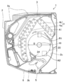
- FIG. 1 is a cross-sectional view of the air conditioning indoor unit according to the embodiment.
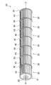
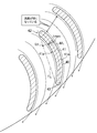
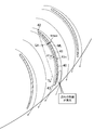
- FIG. 2 is a perspective view of an impeller of the cross flow fan according to the embodiment.
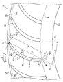
- FIG. 3 is a cross-sectional view of the blade of the cross flow fan according to the embodiment.
- FIG. 4 is a diagram showing the relationship between the ratio of the maximum base thickness tmax to the chord length L and the axial power in the cross flow fan according to the embodiment.
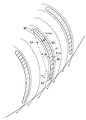
- FIG. 5 is a diagram showing a state of airflow flowing around the blades of the cross flow fan according to the embodiment.
- FIG. 6 is a diagram showing a state of airflow flowing around the blades of the cross-flow fan according to Comparative Example 1.
- FIG. 1 is a cross-sectional view of the air conditioning indoor unit according to the embodiment.
- FIG. 2 is a perspective view of an impeller of the cross flow fan according to the embodiment.
- FIG. 3 is a cross-sectional view of the blade of the cross flow fan according to the embodiment.
- FIG. 7 is a diagram showing a state of airflow flowing around the blades of the cross-flow fan according to Comparative Example 2.
- FIG. 8 is a cross-sectional view of the blade of the cross flow fan according to the first modification.
- FIG. 9 is a cross-sectional view of the blade of the cross flow fan according to the second modification.
- FIG. 10 is an enlarged cross-sectional view showing the outer edge portion of the blade of the cross flow fan shown in FIG.
- FIG. 1 is a cross-sectional view of the air conditioning indoor unit (1) according to the present embodiment.
- the air conditioning indoor unit (1) mainly includes a main body casing (2), an air filter (3), an indoor heat exchanger (4), a cross flow fan (10), and a vertical flap. It is equipped with (5) and a horizontal flap (6).
- "R1" and “R2" indicate a suction region and a blowout region in the cross flow fan (10), respectively.
- a suction port (2a) is provided on the top surface of the main body casing (2).
- An air filter (3) is arranged on the downstream side of the suction port (2a) so as to face the suction port (2a).
- An indoor heat exchanger (4) is arranged further downstream of the air filter (3).
- the indoor heat exchanger (4) is configured by connecting the front side heat exchanger (4a) and the back side heat exchanger (4b) so as to form an inverted V shape in a side view.
- the front side heat exchanger (4a) and the back side heat exchanger (4b) are each configured by arranging a large number of plate fins in parallel with each other and attaching them to a heat transfer tube.
- the indoor air that passes through the suction port (2a) and reaches the indoor heat exchanger (4) is removed of dust as it passes through the air filter (3).
- Heat exchange occurs when the indoor air sucked from the suction port (2a) and passed through the air filter (3) passes between the plate fins of the front side heat exchanger (4a) and the rear side heat exchanger (4b). It is said.
- a substantially cylindrical cross-flow fan (10) having a fan diameter D extends in the width direction (direction perpendicular to the paper surface of FIG. 1) of the air-conditioning indoor unit (1). It is provided in.
- the cross-flow fan (10) is arranged parallel to the indoor heat exchanger (4).
- the cross-flow fan (10) consists of an impeller (20) arranged so as to be sandwiched between inverted V-shaped indoor heat exchangers (4) and a fan motor (not shown) for driving the impeller (20).
- the cross-flow fan (10) rotates the impeller (20) in the direction of arrow A1 (clockwise) in FIG. 1 to generate an air flow from the indoor heat exchanger (4) to the outlet (2b). That is, the cross-flow fan (10) is a cross-flow fan in which the airflow crosses the cross-flow fan (10).
- the air outlet (2b) is provided on the bottom surface of the main body casing (2).
- the back side of the outlet passage connected to the outlet (2b) downstream of the cross flow fan (10) is composed of a scroll member (2c).
- the lower end of the scroll member (2c) is connected to the trailing edge of the outlet (2b).
- the guide surface of the scroll member (2c) is on the side of the cross flow fan (10) in the cross-sectional view in order to smoothly and quietly guide the air blown from the cross flow fan (10) to the outlet (2b). It has a smooth curved shape with a center of curvature.
- a tongue portion (2d) is provided on the front side of the cross flow fan (10), and the upper surface of the outlet passage leading from the tongue portion (2d) is connected to the front edge of the outlet (2b).
- the direction of the airflow blown out from the outlet (2b) is regulated by the vertical flap (5) and the horizontal flap (6).
- FIG. 2 is a perspective view of the impeller (20) of the cross flow fan (10).
- the impeller (20) has a structure in which a plurality of (for example, seven) fan blocks (30) are joined in series, and end plates (21) and (24) are at both ends of the structure. ) Is provided.
- the impeller (20) has a metal rotating shaft (22) on the axis (O). The end of the rotating shaft (22) protrudes from the end plate (21) arranged at one end of the impeller (20), and the end is supported by the main body casing (2).
- a motor (not shown) for driving the rotating shaft (22) is provided on the end plate (24) side arranged at the other end of the impeller (20).
- Each fan block (30) is equipped with a plurality of wings (40) and an annular support plate (50).
- the plurality of wings (40) are arranged around the axis of rotation (22) with the axis of rotation (22) as the center.
- Adjacent wings (40) are arranged at a predetermined interval. Both ends of each wing (40) (both ends in the extending direction of the axis of rotation (22)) are either by a pair of support plates (50) or with the support plate (50) and end plate (21) or end plate (24). Supported by.
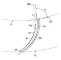
- FIG. 3 is a cross-sectional view (cross-sectional view taken along a plane parallel to the support plate (50)) of the blade (40) of the cross-flow fan (10).
- the annular support plate (50) has an inner peripheral end (51) on the inner peripheral side of the cross flow fan (10) and an outer peripheral end on the outer peripheral side of the cross flow fan (10).
- All wings (40) arranged in one fan block (30) have one inscribed circle (IL) and one circumscribed circle (OL) concentric with the inner peripheral end (51) and the outer peripheral end (52). ) Is placed in contact with it.
- IL inscribed circle
- OL circumscribed circle
- Each wing (40) has an inner edge portion (42) arranged on the inner peripheral side of the cross flow fan (10), an outer edge portion (43) arranged on the outer peripheral side of the cross flow fan (10), and an inner edge portion. It includes a base portion (41) formed between the (42) and the outer edge portion (43).
- the inner edge portion (42) is formed so as to have a convex arc shape on the inner peripheral end (51) side, and is in contact with the inscribed circle (IL).
- the outer edge portion (43) is formed so as to have a convex arc shape on the outer peripheral end (52) side, and is in contact with the circumscribed circle (OL).
- the base portion (41) has a pressure surface (41p) that generates a positive pressure on the side in the direction of arrow A1 (hereinafter referred to as a fan rotation direction) and a negative pressure surface (41n) that generates a negative pressure on the opposite side in the fan rotation direction. ..
- Each blade (40) is a forward blade that curves in the fan rotation direction toward the outer peripheral end (52).
- the blade (40) has an angle ⁇ with respect to a line (RL) orthogonal to the axis (O) of the cross-flow fan (10) and extending radially from the axis (O) toward the outer circumference.
- the inclination ⁇ of the wing (40) is defined by the angle formed by the tangent line (TL) tangent to the inner edge portion (42) and the outer edge portion (43) of the wing (40) and the line extending radially (RL).
- the pressure surface (41p) and negative pressure surface (41n) of the blade (40) are curved so as to draw a bulging arc on the opposite side in the fan rotation direction, respectively.
- both the center of curvature of the arc of the pressure plane (41p) and the center of curvature of the arc of the negative pressure plane (41n) are located on the fan rotation direction side.
- the chord length L of the wing (40) is the length from the end of the inner edge portion (42) to the end of the outer edge portion (43). Specifically, the tangent line (TL) of the wing (40) is extended to the inner peripheral side and the outer peripheral side, respectively, and the perpendicular line (PL1) and the tangent line (TL) that are in contact with the inner edge portion (42) erected on the tangent line (TL), respectively. ), The length from the perpendicular (PL1) to the perpendicular (PL2) becomes the chord length L when the perpendicular (PL2) in contact with the outer edge (43) is drawn.
- the thickness (thickness) of the base (41) that is, the distance between the pressure surface (41p) and the negative pressure surface (41n) gradually changes from the inner peripheral side to the outer peripheral side.
- the maximum thickness position There is a position where the thickness of the base (41) is maximized (hereinafter referred to as the maximum thickness position).
- the maximum thickness of the base (41) is tmax.
- the thickness of the base (41) is defined as the distance between the pressure surface (41p) and the negative pressure surface (41n) in the direction perpendicular to the pressure surface (41p).
- the maximum thickness position (Lt) connects the midpoints of the center line (ML) (pressure surface (41p) and negative pressure surface (41n)) at the location where the maximum thickness is tmax in order. It is represented by the position of the foot of the perpendicular line drawn from the line obtained by) to the tangent line (TL).
- the maximum thickness position (Lt) of the base portion (41) is the inner edge portion (42) on the tangent line (TL) rather than the outer edge portion (43) (outer edge end (CLo)). It is set to the side closer to (inner edge (CLi)).
- the maximum thickness position (Lt) may be set in the range of 5% or more and 45% or less of the chord length L from the inner edge end (CLi) on the tangent line (TL).
- the thickness ti of the inner edge portion (42) is set to be larger than the thickness to of the outer edge portion (43). For example, ti / to> 1.5, more preferably ti / to> 1.75.
- FIG. 4 is a diagram showing the relationship between the ratio tmax / L of the base maximum thickness tmax to the chord length L and the axial power in the blade (40) of the cross flow fan (10) of the present embodiment.
- the size of one scale on the vertical axis of FIG. 4 is 0.1 W.
- the relationship shown in FIG. 4 is a performance evaluation result based on a simulation in a state where the cross flow fan (10) is incorporated in the air conditioner indoor unit (1) (wall-mounted indoor unit) of the room air conditioner. Specifically, for each ratio tmax / L, the shaft power (power of the rotating shaft (22)) when the same air volume is obtained by changing the fan rotation speed is evaluated. If the air volume is in the air volume range of a general air-conditioning indoor unit (for example, 7 to 25 m 3 / min), the same relationship as in FIG. 4 can be obtained.
- the input (power consumption) to the motor that rotates the rotating shaft (22) is a value obtained by dividing the shaft power by the motor efficiency, and if the shaft power is reduced, the power consumption of the motor is also reduced.
- the blade shape (cross-sectional shape) of the cross flow fan (10) used for the evaluation shown in FIG. 4 is as described above.
- the number of blades (the number of blades (40) provided in one fan block (30)) is the same as in FIG. 4 as long as the number of blades (for example, 31 to 37) of a cross-flow fan of a general air-conditioning indoor unit. Relationship is obtained.
- the evaluation shown in FIG. 4 is based on a simulation in which the blade pitch (distance between adjacent blades (40)) is equal pitch, but the inequality applied to the cross flow fan of a general air-conditioning indoor unit. Even with the pitch, the same relationship as in FIG. 4 can be obtained.
- tmax / L ⁇ 0.094 is preferable, and 0.054 ⁇ tmax / L ⁇ 0.094. Is more preferable, and 0.074 ⁇ tmax / L ⁇ 0.086 is most preferable.
- tmax / L is set to 0.054 or more in the blade (40) of the cross flow fan (10) of the present embodiment, the maximum thickness tmax of the base portion (41) is made too thin, which causes a negative effect. It is possible to avoid a situation in which the effect of suppressing flow separation is reduced on the pressure surface (41n).
- tmax / L when tmax / L is set to 0.074 or more and 0.086 or less, a sufficient width of the inter-blade flow path is secured and the flow velocity is increased. It is possible to obtain the effect of further suppressing the separation of the flow on the negative pressure surface (41n) while further suppressing it.
- the maximum thickness position (Lt) of the base portion (41) is from the end of the inner edge portion (42) (the inner edge end (CLi) in FIG. 3).
- the separation of the flow on the negative pressure surface (41n) can be further suppressed.
- the thickness ti of the inner edge portion (42) is set to be larger than the thickness to of the outer edge portion (43). Therefore, from the inner edge portion (42) to the vicinity of the central portion of the blade (40), the thickness of the base portion (41) gradually decreases, so that the curvature of the blade surface on the negative pressure surface (41n) does not increase. Therefore, even if the flow is about to separate on the negative pressure surface (41n) side, the airflow immediately reattaches to the negative pressure surface (41n), so that the flow from the inner edge (42) to the center of the blade (40) Peeling can be suppressed.
- the thickness is greatly reduced from the central portion of the blade (40) to the outer edge portion (43), it is possible to maintain a wide inter-blade flow path width from the central portion to the outer edge portion (43) of the blade (40). it can. As a result, it is possible to efficiently utilize the wide inter-blade flow path width and reduce the blown wind speed between the blades.
- the width of the flow path between the blades can be secured and the increase in the flow velocity can be suppressed. Energy efficiency is improved because the loss at the wing (40) can be suppressed.
- the cross flow fan (10) of the present embodiment when the fan diameter D is 126 mm or more, the following effects can be obtained.
- the chord length L is also larger than that of the small-diameter cross-flow fan.
- the maximum thickness tmax of the base (41) is tmax / L ⁇ 0.094, which makes it possible to significantly reduce the thickness of the blade compared to a small-diameter cross-flow fan, resulting in weight reduction and material cost reduction. The effect is also great.
- the energy efficiency of the cross-flow fan (10) is improved, so that the power consumption can be reduced.
- FIG. 5 is a diagram showing a state of airflow flowing around the blade (40) of the cross flow fan (10) of the present embodiment located in the blowout region R2 (see FIG. 1).
- the maximum thickness position (Lt) of the base portion (41) exists on the side closer to the inner edge portion (42) than the outer edge portion (43).
- the separation of the flow on the negative pressure surface (41n) from the inner edge portion (42) to the outer edge portion (43) of the blade (40) is suppressed. Therefore, the flow from the inner edge portion (42) to the outer edge portion (43) is promoted, and the generation of turbulent flow is suppressed, so that the generation of low-frequency narrow-band noise and the like is suppressed.
- tmax / L is set to 0.094 or less, it is possible to secure the width of the flow path between blades and suppress an increase in the flow velocity.
- FIG. 6 is a diagram showing a state of airflow flowing around the blade (40) of the cross flow fan according to Comparative Example 1 in which tmax / L is set to be larger than 0.094. Note that FIG. 6 also shows the state of the air flow in the blowout region. Further, also in Comparative Example 1, the maximum thickness position (Lt) of the base portion (41) exists on the side closer to the inner edge portion (42) than the outer edge portion (43), and the blade pitch is the same as that shown in FIG. The same is true.
- FIG. 7 is a diagram showing a state of airflow flowing around the blade (40) of the cross flow fan according to Comparative Example 2 in which tmax / L is set to be smaller than 0.054. Note that FIG. 7 also shows the state of the air flow in the blowout region. Further, also in Comparative Example 2, the maximum thickness position (Lt) of the base portion (41) exists on the side closer to the inner edge portion (42) than the outer edge portion (43), and the blade pitch is the same as that shown in FIG. The same is true.
- FIG. 8 is a cross-sectional view of the blade (40) of the cross flow fan (10) according to the first modification.
- the same components as those in the embodiment shown in FIG. 3 are designated by the same reference numerals.
- the outer shape of the wing (40) shown in FIG. 3 is shown by a broken line.
- the state of the air flow flowing near the negative pressure surface (41n) of the blade (40) in the cross flow fan (10) of the present modification located in the blowout region R2 (see FIG. 1) is shown by an arrow. ..
- the feature of the wing (40) of this modified example shown in FIG. 8 is that the entrance angle ⁇ of the inner edge portion (42) is set to 80 ° or more and 90 ° or less, for example, 86 °. That is, the warp of the wing (40) of the present modification is set to be smaller than the warp of the wing (40) of the above embodiment (the entrance angle ⁇ of the inner edge portion (42) is, for example, 92.7 °).
- the entrance angle ⁇ of the inner edge portion (42) is defined as follows.
- the inlet angle ⁇ of the inner edge portion (42) is set to 80 ° or more and 90 ° or less, so that the wing ( Since the warp of 40) becomes small, the airflow becomes easy to flow along the negative pressure surface (41n) of the wing (40). Therefore, since the separation of the flow on the negative pressure surface (41n) can be further suppressed, the loss on the blade (40) can be further suppressed, and the energy efficiency of the cross flow fan (10) is further improved.
- FIG. 9 is a cross-sectional view of the blade (40) of the cross flow fan (10) according to the second modification
- FIG. 10 is an outer edge portion (43) of the blade (40) of the cross flow fan (10) shown in FIG. ) Is an enlarged cross-sectional view.
- the same components as those in the embodiment shown in FIG. 3 are designated by the same reference numerals.
- the outer shape of the wing (40) shown in FIG. 3 is shown by a broken line.
- FIGS. 9 and 10 the state of the air flow flowing near the negative pressure surface (41n) of the blade (40) in the cross flow fan (10) of the present modification located in the suction region R1 (see FIG. 1) is indicated by an arrow. Shown.
- the surface of the outer edge portion (43) on the negative pressure surface (41n) side is an outwardly convex curved surface (ws) and is curved.
- the surface (ws) is to be smoothly connected to the negative pressure surface (41n). That is, the radius of curvature of the curved surface (ws) is larger than the radius of curvature of the surface of the outer edge portion (43) of the embodiment.
- the curved surface (ws) is connected to the pressure surface (41p) at an angle of 85 ° or more and 90 ° or less.
- the angle ⁇ is It is 0 ° or more and 5 ° or less.
- the surface of the outer edge portion (43) on the negative pressure surface (41n) side is an outwardly convex curved surface (ws), and the curved surface (ws) is smoothly connected to the negative pressure surface (41n) and the pressure is increased. It is connected to the surface (41p) at an angle of 85 ° or more and 90 ° or less. Therefore, the airflow that has reached the vicinity of the outer edge portion (43) of the blade (40) tends to flow along the negative pressure surface (41n). Therefore, since the separation of the flow on the negative pressure surface (41n) can be further suppressed, the loss on the blade (40) can be further suppressed, and the energy efficiency of the cross flow fan (10) is further improved.
- the following configuration may be used. That is, the surface of the inner edge portion (42) on the negative pressure surface (41n) side is an outwardly convex curved surface, and the curved surface is smoothly connected to the negative pressure surface (41n) and is connected to the pressure surface (41p). Are connected at an angle of 85 ° or more and 90 ° or less. By doing so, the same effect as in this modification can be obtained in the blowout region R2 (see FIG. 1).
- the wall-mounted indoor unit has been described as the air-conditioning indoor unit (1) provided with the cross-flow fan (10), but the present invention is not limited to this, and the cross-flow fan (10) is placed on the floor. It may be used for other types of indoor units such as a type and a ceiling-mounted type.
- the impeller (20) of the cross flow fan (10) is arranged on the downstream side in the direction in which air flows with respect to the indoor heat exchanger (4), but instead of this. Therefore, the impeller (20) may be arranged on the upstream side of the indoor heat exchanger (4).
- the present disclosure is useful for cross-flow fan wings, cross-flow fans, and air-conditioning indoor units.
- Air-conditioning indoor unit Main body casing 2a Suction port 2b Air outlet 2c Scroll member 2d Tongue part 3 Air filter 4 Indoor heat exchanger 4a Front side heat exchanger 4b Rear side heat exchanger 5 Vertical flap 6 Horizontal flap 10 Cross flow fan 20 Impeller 21 End plate 22 Rotating shaft 24 End plate 30 Fan block 40 Wing 41 Base 41p Pressure surface 41n Negative pressure surface 42 Inner edge 43 Outer edge 50 Support plate 51 Inner peripheral edge 52 Outer edge
Abstract
Description
〈空調室内機の構成〉
図1は、本実施形態に係る空調室内機(1)の断面図である。図1に示すように、空調室内機(1)は、主として、本体ケーシング(2)と、エアフィルタ(3)と、室内熱交換器(4)と、クロスフローファン(10)と、垂直フラップ(5)と、水平フラップ(6)とを備える。尚、図1において、「R1」、「R2」はそれぞれ、クロスフローファン(10)における吸い込み領域、吹き出し領域を示す。
図2は、クロスフローファン(10)の羽根車(20)の斜視図である。図2に示すように、羽根車(20)は、複数(例えば7つ)のファンブロック(30)を直列に接合した構造を有し、当該構造の両端にはエンドプレート(21)、(24)が設けられる。羽根車(20)は、軸心(O)上に金属製の回転軸(22)を有する。羽根車(20)の一端に配置されたエンドプレート(21)からは、回転軸(22)の端部が突き出ており、当該端部は本体ケーシング(2)によって支持される。羽根車(20)の他端に配置されたエンドプレート(24)側には、回転軸(22)を駆動するモーター(図示省略)が設けられる。
図3は、クロスフローファン(10)の翼(40)の断面図(支持プレート(50)に平行な平面で切断した断面図)である。図3に示すように、円環状の支持プレート(50)は、クロスフローファン(10)の内周側にある内周端(51)と、クロスフローファン(10)の外周側にある外周端(52)とを有する。1つのファンブロック(30)に配置される全ての翼(40)は、内周端(51)及び外周端(52)と同心円状の1つの内接円(IL)及び1つの外接円(OL)に接するように配置される。
図4は、本実施形態のクロスフローファン(10)の翼(40)における、翼弦長Lに対する基部最大厚みtmaxの比率tmax/Lと、軸動力との関係を示す図である。尚、図4の縦軸の1目盛りの大きさは、0.1Wである。
以上に説明した本実施形態のクロスフローファン(10)の翼(40)によると、翼弦長Lに対する基部(41)の最大厚みtmaxの比率tmax/Lを0.094以下に設定することにより、翼間流路幅を確保して流速の増大を抑制できる。また、基部(41)の最大厚み位置(Lt)を内縁部(42)に近い側に設定することにより、負圧面(41n)での流れの剥離を抑制できる。このため、翼(40)での損失を抑制できるので、クロスフローファン(10)のエネルギー効率が向上する。
図5は、吹き出し領域R2(図1参照)に位置する本実施形態のクロスフローファン(10)の翼(40)の周囲を流れる気流の様子を示す図である。
図6は、tmax/Lが0.094よりも大きく設定された比較例1に係るクロスフローファンの翼(40)の周囲を流れる気流の様子を示す図である。尚、図6も吹き出し領域での気流の様子を示す。また、比較例1においても、基部(41)の最大厚み位置(Lt)は、外縁部(43)よりも内縁部(42)に近い側に存在し、翼ピッチは、図5に示す場合と同様である。
図7は、tmax/Lが0.054よりも小さく設定された比較例2に係るクロスフローファンの翼(40)の周囲を流れる気流の様子を示す図である。尚、図7も吹き出し領域での気流の様子を示す。また、比較例2においても、基部(41)の最大厚み位置(Lt)は、外縁部(43)よりも内縁部(42)に近い側に存在し、翼ピッチは、図5に示す場合と同様である。
図8は、変形例1に係るクロスフローファン(10)の翼(40)の断面図である。尚、図8において、図3に示す前記実施形態と同じ構成要素には同じ符号を付している。また、図8において、図3に示す翼(40)の外形を破線で示している。また、図8において、吹き出し領域R2(図1参照)に位置する本変形例のクロスフローファン(10)における翼(40)の負圧面(41n)近傍を流れる気流の様子を矢印で示している。
図9は、変形例2に係るクロスフローファン(10)の翼(40)の断面図であり、図10は、図9に示すクロスフローファン(10)の翼(40)の外縁部(43)を拡大して示す断面図である。尚、図9及び図10において、図3に示す前記実施形態と同じ構成要素には同じ符号を付している。また、図9及び図10において、図3に示す翼(40)の外形を破線で示している。また、図9及び図10において、吸い込み領域R1(図1参照)に位置する本変形例のクロスフローファン(10)における翼(40)の負圧面(41n)近傍を流れる気流の様子を矢印で示している。
前記実施形態及び変形例では、クロスフローファン(10)を備える空調室内機(1)として、壁掛けタイプの室内機について説明したが、これに限定されず、クロスフローファン(10)は、床置きタイプ、天井設置タイプなどの他のタイプの室内機に用いてもよい。
2 本体ケーシング
2a 吸込口
2b 吹出口
2c スクロール部材
2d 舌部
3 エアフィルタ
4 室内熱交換器
4a 前面側熱交換器
4b 背面側熱交換器
5 垂直フラップ
6 水平フラップ
10 クロスフローファン
20 羽根車
21 エンドプレート
22 回転軸
24 エンドプレート
30 ファンブロック
40 翼
41 基部
41p 圧力面
41n 負圧面
42 内縁部
43 外縁部
50 支持プレート
51 内周端
52 外周端
Claims (9)
- クロスフローファン(10)の内周側に配置された内縁部(42)と、
前記クロスフローファン(10)の外周側に配置された外縁部(43)と、
前記内縁部(42)と前記外縁部(43)との間に形成され、圧力面(41p)及び負圧面(41n)を有する基部(41)とを備え、
前記内縁部(42)の厚みは、前記外縁部(43)の厚みよりも大きく、
前記基部(41)の最大厚み位置は、前記外縁部(43)よりも前記内縁部(42)に近い側に設定され、
翼弦長をL、前記基部(41)の最大厚みをtmaxとすると、tmax/L≦0.094であることを特徴とするクロスフローファンの翼。 - 請求項1において、
0.054≦tmax/Lであることを特徴とするクロスフローファンの翼。 - 請求項1又は2において、
0.074≦tmax/L≦0.086であることを特徴とするクロスフローファンの翼。 - 請求項1~3のいずれか1項において、
前記基部(41)の前記最大厚み位置は、前記内縁部(42)の端から前記翼弦長の5%以上45%以下の範囲に設定されることを特徴とするクロスフローファンの翼。 - 請求項1~4のいずれか1項において、
前記内縁部(42)における入口角は、80°以上90°以下に設定されることを特徴とするクロスフローファンの翼。 - 請求項1~5のいずれか1項において、
前記内縁部(42)及び前記外縁部(43)の少なくとも一方における前記負圧面(41n)側の表面は、外側に凸の湾曲面であり、
前記湾曲面は、前記負圧面(41n)とは滑らかに接続され、前記圧力面(41p)とは85°以上90°以下の角度で接続されることを特徴とするクロスフローファンの翼。 - 請求項1~6のいずれか1項に記載の翼(40)が回転軸(22)の周囲に複数枚配列されたことを特徴とするクロスフローファン。
- 請求項7において、
ファン径は、126mm以上であることを特徴とするクロスフローファン。 - 請求項7又は8に記載のクロスフローファン(10)を備えることを特徴とする空調室内機。
Priority Applications (4)
| Application Number | Priority Date | Filing Date | Title |
|---|---|---|---|
| CN202080067221.4A CN114502842B (zh) | 2019-09-30 | 2020-06-01 | 横流风扇的叶片、横流风扇和空调室内机 |
| AU2020359245A AU2020359245B2 (en) | 2019-09-30 | 2020-06-01 | Cross flow fan blade, cross flow fan, and air conditioner indoor unit |
| EP20870951.9A EP4027018A4 (en) | 2019-09-30 | 2020-06-01 | CROSS FLOW FAN BLADE, CROSS FLOW FAN AND AIR CONDITIONER INDOOR UNIT |
| US17/701,491 US11466871B2 (en) | 2019-09-30 | 2022-03-22 | Cross flow fan blade, cross flow fan, and air conditioner indoor unit |
Applications Claiming Priority (2)
| Application Number | Priority Date | Filing Date | Title |
|---|---|---|---|
| JP2019-179027 | 2019-09-30 | ||
| JP2019179027A JP6852768B1 (ja) | 2019-09-30 | 2019-09-30 | クロスフローファンの翼、クロスフローファン及び空調室内機 |
Related Child Applications (1)
| Application Number | Title | Priority Date | Filing Date |
|---|---|---|---|
| US17/701,491 Continuation US11466871B2 (en) | 2019-09-30 | 2022-03-22 | Cross flow fan blade, cross flow fan, and air conditioner indoor unit |
Publications (1)
| Publication Number | Publication Date |
|---|---|
| WO2021065079A1 true WO2021065079A1 (ja) | 2021-04-08 |
Family
ID=75154708
Family Applications (1)
| Application Number | Title | Priority Date | Filing Date |
|---|---|---|---|
| PCT/JP2020/021573 WO2021065079A1 (ja) | 2019-09-30 | 2020-06-01 | クロスフローファンの翼、クロスフローファン及び空調室内機 |
Country Status (6)
| Country | Link |
|---|---|
| US (1) | US11466871B2 (ja) |
| EP (1) | EP4027018A4 (ja) |
| JP (1) | JP6852768B1 (ja) |
| CN (1) | CN114502842B (ja) |
| AU (1) | AU2020359245B2 (ja) |
| WO (1) | WO2021065079A1 (ja) |
Citations (6)
| Publication number | Priority date | Publication date | Assignee | Title |
|---|---|---|---|---|
| JP2001274486A (ja) * | 2000-01-18 | 2001-10-05 | Ushio Inc | 放電励起ガスレーザ装置用クロスフローファン |
| WO2013051297A1 (ja) * | 2011-10-05 | 2013-04-11 | 日立アプライアンス株式会社 | 空気調和機 |
| JP2014034928A (ja) * | 2012-08-09 | 2014-02-24 | Daikin Ind Ltd | 多翼ファン及びこれを備える空気調和機の室内機 |
| JP2015124766A (ja) | 2013-12-27 | 2015-07-06 | ダイキン工業株式会社 | クロスフローファンの翼 |
| JP2018084154A (ja) * | 2016-11-21 | 2018-05-31 | ダイキン工業株式会社 | クロスフロー型の送風機及びそれを備えた空気調和装置の室内ユニット |
| WO2019012578A1 (ja) * | 2017-07-10 | 2019-01-17 | 三菱電機株式会社 | 空気調和機の室内機 |
Family Cites Families (7)
| Publication number | Priority date | Publication date | Assignee | Title |
|---|---|---|---|---|
| EP1119082A3 (en) | 2000-01-18 | 2004-05-26 | Ushiodenki Kabushiki Kaisha | Cross-flow fan for discharge excited gas laser |
| JP4196346B2 (ja) * | 2004-03-25 | 2008-12-17 | 三菱電機株式会社 | 空気調和機 |
| JP4583095B2 (ja) * | 2004-07-27 | 2010-11-17 | 東芝キヤリア株式会社 | クロスフローファン |
| JP5140986B2 (ja) * | 2006-03-15 | 2013-02-13 | 株式会社デンソー | 遠心式多翼ファン |
| JP5143317B1 (ja) * | 2012-04-06 | 2013-02-13 | 三菱電機株式会社 | 空気調和装置の室内機 |
| CN104728162B (zh) * | 2013-12-24 | 2017-04-12 | 珠海格力电器股份有限公司 | 贯流风叶 |
| WO2018189931A1 (ja) * | 2017-04-10 | 2018-10-18 | シャープ株式会社 | 遠心ファン、成型用金型および流体送り装置 |
-
2019
- 2019-09-30 JP JP2019179027A patent/JP6852768B1/ja active Active
-
2020
- 2020-06-01 AU AU2020359245A patent/AU2020359245B2/en active Active
- 2020-06-01 WO PCT/JP2020/021573 patent/WO2021065079A1/ja unknown
- 2020-06-01 EP EP20870951.9A patent/EP4027018A4/en active Pending
- 2020-06-01 CN CN202080067221.4A patent/CN114502842B/zh active Active
-
2022
- 2022-03-22 US US17/701,491 patent/US11466871B2/en active Active
Patent Citations (6)
| Publication number | Priority date | Publication date | Assignee | Title |
|---|---|---|---|---|
| JP2001274486A (ja) * | 2000-01-18 | 2001-10-05 | Ushio Inc | 放電励起ガスレーザ装置用クロスフローファン |
| WO2013051297A1 (ja) * | 2011-10-05 | 2013-04-11 | 日立アプライアンス株式会社 | 空気調和機 |
| JP2014034928A (ja) * | 2012-08-09 | 2014-02-24 | Daikin Ind Ltd | 多翼ファン及びこれを備える空気調和機の室内機 |
| JP2015124766A (ja) | 2013-12-27 | 2015-07-06 | ダイキン工業株式会社 | クロスフローファンの翼 |
| JP2018084154A (ja) * | 2016-11-21 | 2018-05-31 | ダイキン工業株式会社 | クロスフロー型の送風機及びそれを備えた空気調和装置の室内ユニット |
| WO2019012578A1 (ja) * | 2017-07-10 | 2019-01-17 | 三菱電機株式会社 | 空気調和機の室内機 |
Non-Patent Citations (1)
| Title |
|---|
| See also references of EP4027018A4 |
Also Published As
| Publication number | Publication date |
|---|---|
| AU2020359245B2 (en) | 2022-06-16 |
| EP4027018A4 (en) | 2022-11-09 |
| JP6852768B1 (ja) | 2021-03-31 |
| JP2021055603A (ja) | 2021-04-08 |
| CN114502842A (zh) | 2022-05-13 |
| AU2020359245A1 (en) | 2022-04-07 |
| EP4027018A1 (en) | 2022-07-13 |
| US11466871B2 (en) | 2022-10-11 |
| CN114502842B (zh) | 2023-05-05 |
| US20220214052A1 (en) | 2022-07-07 |
Similar Documents
| Publication | Publication Date | Title |
|---|---|---|
| US9267511B2 (en) | Turbofan and indoor unit of air-conditioning apparatus including the same | |
| US8011891B2 (en) | Centrifugal multiblade fan | |
| WO2007114090A1 (ja) | 多翼ファン | |
| JPH07115579B2 (ja) | 車輌用空気調和装置 | |
| EP2657530A1 (en) | Through-flow fan, and indoor unit for air conditioner | |
| WO2017026143A1 (ja) | 送風機および空気調和装置 | |
| US9303649B2 (en) | Cross flow fan and air-conditioning apparatus including same | |
| JP2002257088A (ja) | 軸流ファン | |
| JPH11141494A (ja) | 多翼送風機の羽根車構造 | |
| JP6444528B2 (ja) | 軸流ファン、及び、その軸流ファンを有する空気調和装置 | |
| WO2015098689A1 (ja) | クロスフローファンの翼 | |
| JP6739656B2 (ja) | 羽根車、送風機、及び空気調和装置 | |
| WO2021065079A1 (ja) | クロスフローファンの翼、クロスフローファン及び空調室内機 | |
| JP2001280288A (ja) | 多翼送風機の羽根車構造 | |
| JP3744489B2 (ja) | 送風機 | |
| WO2015064617A1 (ja) | 貫流ファン及び空気調和機 | |
| JP2002357194A (ja) | 貫流ファン | |
| WO2024084537A1 (ja) | 送風装置 | |
| CN216430052U (zh) | 一种轴流叶轮、轴流风机及空调器 | |
| JP6625291B1 (ja) | 羽根車、送風機及び空気調和機 | |
| JPS6337516Y2 (ja) | ||
| JP6000454B2 (ja) | 空気調和装置の室内機 | |
| WO2019159228A1 (ja) | 送風機及び空気調和装置 | |
| JPH10196590A (ja) | 空気調和機等の送風機 |
Legal Events
| Date | Code | Title | Description |
|---|---|---|---|
| 121 | Ep: the epo has been informed by wipo that ep was designated in this application |
Ref document number: 20870951 Country of ref document: EP Kind code of ref document: A1 |
|
| NENP | Non-entry into the national phase |
Ref country code: DE |
|
| ENP | Entry into the national phase |
Ref document number: 2020359245 Country of ref document: AU Date of ref document: 20200601 Kind code of ref document: A |
|
| ENP | Entry into the national phase |
Ref document number: 2020870951 Country of ref document: EP Effective date: 20220408 |