WO2021064976A1 - ケーブルクランプ、プラズマヘッド、及びケーブルのクランプ方法 - Google Patents
ケーブルクランプ、プラズマヘッド、及びケーブルのクランプ方法 Download PDFInfo
- Publication number
- WO2021064976A1 WO2021064976A1 PCT/JP2019/039233 JP2019039233W WO2021064976A1 WO 2021064976 A1 WO2021064976 A1 WO 2021064976A1 JP 2019039233 W JP2019039233 W JP 2019039233W WO 2021064976 A1 WO2021064976 A1 WO 2021064976A1
- Authority
- WO
- WIPO (PCT)
- Prior art keywords
- clamp
- cables
- cable
- tapered surface
- fixing
- Prior art date
- Legal status (The legal status is an assumption and is not a legal conclusion. Google has not performed a legal analysis and makes no representation as to the accuracy of the status listed.)
- Ceased
Links
Images



Classifications
-
- H—ELECTRICITY
- H02—GENERATION; CONVERSION OR DISTRIBUTION OF ELECTRIC POWER
- H02G—INSTALLATION OF ELECTRIC CABLES OR LINES, OR OF COMBINED OPTICAL AND ELECTRIC CABLES OR LINES
- H02G3/00—Installations of electric cables or lines or protective tubing therefor in or on buildings, equivalent structures or vehicles
- H02G3/30—Installations of cables or lines on walls, floors or ceilings
- H02G3/32—Installations of cables or lines on walls, floors or ceilings using mounting clamps
-
- F—MECHANICAL ENGINEERING; LIGHTING; HEATING; WEAPONS; BLASTING
- F16—ENGINEERING ELEMENTS AND UNITS; GENERAL MEASURES FOR PRODUCING AND MAINTAINING EFFECTIVE FUNCTIONING OF MACHINES OR INSTALLATIONS; THERMAL INSULATION IN GENERAL
- F16B—DEVICES FOR FASTENING OR SECURING CONSTRUCTIONAL ELEMENTS OR MACHINE PARTS TOGETHER, e.g. NAILS, BOLTS, CIRCLIPS, CLAMPS, CLIPS OR WEDGES; JOINTS OR JOINTING
- F16B2/00—Friction-grip releasable fastenings
- F16B2/02—Clamps, i.e. with gripping action effected by positive means other than the inherent resistance to deformation of the material of the fastening
- F16B2/06—Clamps, i.e. with gripping action effected by positive means other than the inherent resistance to deformation of the material of the fastening external, i.e. with contracting action
- F16B2/12—Clamps, i.e. with gripping action effected by positive means other than the inherent resistance to deformation of the material of the fastening external, i.e. with contracting action using sliding jaws
-
- F—MECHANICAL ENGINEERING; LIGHTING; HEATING; WEAPONS; BLASTING
- F16—ENGINEERING ELEMENTS AND UNITS; GENERAL MEASURES FOR PRODUCING AND MAINTAINING EFFECTIVE FUNCTIONING OF MACHINES OR INSTALLATIONS; THERMAL INSULATION IN GENERAL
- F16B—DEVICES FOR FASTENING OR SECURING CONSTRUCTIONAL ELEMENTS OR MACHINE PARTS TOGETHER, e.g. NAILS, BOLTS, CIRCLIPS, CLAMPS, CLIPS OR WEDGES; JOINTS OR JOINTING
- F16B7/00—Connections of rods or tubes, e.g. of non-circular section, mutually, including resilient connections
- F16B7/22—Connections of rods or tubes, e.g. of non-circular section, mutually, including resilient connections using hooks or like elements
-
- H—ELECTRICITY
- H02—GENERATION; CONVERSION OR DISTRIBUTION OF ELECTRIC POWER
- H02G—INSTALLATION OF ELECTRIC CABLES OR LINES, OR OF COMBINED OPTICAL AND ELECTRIC CABLES OR LINES
- H02G11/00—Arrangements of electric cables or lines between relatively-movable parts
Definitions
- This disclosure relates to a cable clamp for fixing a plurality of cables.
- the cable fixing structure described in Patent Document 1 below has a hollow cylindrical shape in which a first hole for inserting a cable is formed, and has a truncated cone-shaped portion having a tapered outer peripheral surface and the tapered shape.
- a rubber bush having a stepped cut, an open end into which the rubber bush is inserted, and a cylindrical portion when the rubber bush is inserted from the cylindrical portion side.
- a wall surface portion having a side surface portion abutting on the circumferential surface and a flat portion supporting the bottom portion of the cylindrical portion, and a tapered surface formed so as to expand in diameter toward the wall surface portion and the open end.
- bracket to be attached to the panel, a second hole for inserting the cable, and a nut to be screwed into the bracket, and the cable is inserted into the first and second holes.
- the rubber bush is inserted into the bracket, and the bracket and the nut are screwed together.
- the present disclosure has been made in view of the above points, and it is an object of the present invention to provide a cable clamp capable of improving the fixing force for a plurality of cables and reducing the size at the same time.
- a fixing portion through which a plurality of cables are inserted, a recess provided in the fixing portion and exposed by the plurality of cables, a first tapered surface forming the recess, and a fixing portion fitted in the recess.
- a cable clamp comprising a clamp portion that is clamped to the cable and a second tapered surface that is provided on the clamp portion and is pressed toward a first tapered surface in contact with a plurality of cables.
- the cable clamp can both improve the fixing force for a plurality of cables and reduce the size.
- the plasma processing machine 1 includes a table 10 on which the work W is placed and a serial link type robot (also referred to as a multi-indirect type robot) arranged beside the table 10.
- a serial link type robot also referred to as a multi-indirect type robot
- a robot abbreviated as a robot
- the lower part of the plasma head 14 is a nozzle 30 that discharges a plasmatized gas.
- the plasma processing machine 1 includes a power supply gas supply unit 16 that is a power source for the plasma head 14 and is responsible for supplying gas to the plasma head 14, and a controller 18 (computer) as a control device that controls the plasma processing machine 1. Is the main component) and is included.
- a plurality of external cables 60 are connected between the plasma head 14 and the power supply gas supply unit 16.
- the robot 12 functions as a head moving device that moves the plasma head 14 in order to irradiate the work W with the plasma-ized gas.
- the power supply gas supply unit 16 includes a touch panel 17 in addition to a CPU, ROM, RAM, etc. (not shown). On the touch panel 17, various setting screens, operating states, and the like are displayed for the power gas supply unit 16, and operation information is input by the user touching the screen.
- a cable clamp is provided in the plasma head 14.
- the cable clamp fixes a plurality of internal cables connected to the plurality of external cables 60 to the plasma head 14.
- the cable clamp will be described.
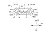
- the cable clamp 20 fixes the internal cables 22L and 22R.
- the letters L and R attached to the code indicate the left side and the right side. However, when generically referred to without distinguishing left and right, the letters L and R shall be written without being attached to the code.
- the cable clamp 20 includes a fixing portion 40 and a clamp portion 70.
- the fixed portion 40 includes a main body 42. Protruding portions 44L and 44R protruding downward are provided on the left and right ends of the main body 42. Through holes 46L and 46R parallel to the vertical direction D1 are formed in the protruding portions 44L and 44R. Internal cables 22L and 22R are inserted into the through holes 46L and 46R. Therefore, the internal cables 22L and 22R in the fixed portion 40 are in a state parallel to the vertical direction D1.
- the protrusions 44L and 44R are formed with recesses 48L and 48R from the inside to the rear facing each other.
- the recesses 48L and 48R are composed of upper surfaces 50L and 50R, front surfaces 52L and 52R, and side surfaces 54L and 54R.
- Bolt holes 56L and 56R parallel to the front-rear direction D3 are formed on the front surfaces 52L and 52R.
- the side surfaces 54L and 54R are tapered surfaces and are inclined so as to approach each other toward the front.
- the side surfaces 54L and 54R and the front surfaces 52L and 52R are separated from each other so that the internal cables 22L and 22R are exposed portions 55L and 55R.
- the clamp portion 70 has a substantially rectangular parallelepiped shape, and is composed of an upper surface 72, a lower surface 74, a front surface 76, a rear surface 78, a left surface 80, and a right surface 82.
- the left surface 80 and the right surface 82 are tapered surfaces and are inclined so as to approach each other toward the front.
- a plurality of groove portions 84 are formed on the left surface 80.
- the plurality of groove portions 84 are provided in parallel with each other at predetermined intervals in the vertical direction D1. That is, the plurality of groove portions 84 are provided on the left surface 80 along the direction orthogonal to the vertical direction D1.
- a plurality of groove portions 86 are formed on the right surface 82.
- the plurality of groove portions 86 are provided in parallel with each other at predetermined intervals in the vertical direction D1. That is, the plurality of groove portions 86 are provided on the right surface 82 along the direction orthogonal to the vertical direction D1.
- a pair of groove recesses 88 and 88 are formed on the upper surface 72.
- the pair of groove recesses 88, 88 are provided parallel to each other along the front-rear direction D3.
- the surface distance of the upper surface 72 in the left-right direction D2 is longer than that of the flat surface 72.
- a pair of groove recesses 90, 90 are formed on the lower surface 74.
- the pair of groove recesses 90, 90 are provided parallel to each other along the front-rear direction D3.
- the lower surface 74 has a longer surface distance in the left-right direction D2 than the flat surface.
- the front surface 76 is provided with an uneven portion 92.
- the uneven portion 92 is uneven as the front surface 76 advances to the left or right side.
- the front surface 76 has a longer surface distance in the left-right direction D2 than the flat surface.
- a pair of mounting holes 94 are provided through the front surface 76.
- a pair of bolts 96, 96 are inserted through the pair of mounting holes 94.
- the cable clamping method is a method of fixing the internal cables 22L and 22R by using the cable clamp 20. As shown in FIG. 5, in the cable clamping method 100, the fitting step S10, the pressing step S12, and the tightening step S14 are performed in the order described.
- the clamp portion 70 has a clamp portion 70 with respect to the recesses 48L and 48R of the fixing portion 40 in a state where the internal cables 22L and 22R are inserted into the through holes 46L and 46R. , The front surface 76 is fitted in a state of facing forward.
- the left surface 80 and the right surface 82 of the clamp portion 70 are pressed toward the side surfaces 54L and 54R of the recesses 48L and 48R of the fixing portion 40.
- the internal cables 22L and 22R appearing there, and a part of each of the front surface 76, the left surface 80, and the right surface 82 of the clamp portion 70. Is in contact with.
- the pair of bolts 96 and 96 are screwed into the bolt holes 56L and 56R of the recesses 48L and 48R of the fixing portion 40 in a state of being inserted into the pair of mounting holes 94 of the clamp portion 70.
- the left surface 80 and the right surface 82 of the clamp portion 70 are pressed against the side surfaces 54L and 54R of the recesses 48L and 48R of the fixing portion 40.
- each part of the front surface 76, the left surface 80 and the right surface 82 of the clamp portion 70 is pressed against the internal cables 22L and 22R.
- the upper surface 72 and the lower surface 74 are in contact with the internal cables 22L and 22R adjacent to each other.
- the internal cables 22L and 22R are fixed by tightening the clamp portion 70 to the fixing portion 40 by the fastening force of the pair of bolts 96 and 96.
- the left surface 80 and the right surface 82 of the clamp portion 70 are tapered surfaces that incline so as to approach each other as the pair of bolts 96 and 96 are screwed in the front direction.
- the side surfaces 54L, 54R of the recesses 48L, 48R of the fixing portion 40 are tapered surfaces that incline toward each other as the pair of bolts 96, 96 are screwed in the front direction.
- the internal cables 22L and 22R are fixed with a force larger than the fastening force of the pair of bolts 96 and 96.
- the wedge effect for improving the fixing force of the internal cables 22L and 22R is caused by the tapered surface, so that there is no problem even if the cable clamp 20 is miniaturized.
- the plurality of groove portions 84 formed on the left surface 80 of the clamp portion 70 are parallel to each other on the left surface 80 of the clamp portion 70 in a direction orthogonal to the vertical direction D1. Therefore, the plurality of groove portions 84 are pressed against the side surface 54L of the recess 48L of the fixing portion 40 while intersecting with the internal cables 22L and 22R which are in a state parallel to the vertical direction D1 in the fixing portion 40. This point is the same for the plurality of groove portions 86 formed on the right surface 82 of the clamp portion 70.
- the uneven portion 92 formed on the front surface 76 is located between the internal cables 22L and 22R inserted through the fixing portion 40. As it travels in the left-right direction D2, that is, as it goes from one of the internal cables 22L and 22R to the other, it becomes uneven.
- a pair of groove recesses 88 and 88 formed in the upper surface 72 along the front-rear direction D3 are inserted into the fixing portion 40. It is located between the internal cables 22L and 22R.
- the upper surface 72 of the clamp portion 70 is uneven as it advances in the left-right direction D2, that is, as it goes from one of the internal cables 22L and 22R to the other. This point also applies to the pair of groove recesses 90, 90 formed on the lower surface 74 of the clamp portion 70.
- the present embodiment makes it possible to improve the fixing force to the two internal cables 22 and to reduce the size of the cable clamp 20 by the wedge effect due to the tapered surface.
- the two internal cables 22 are an example of a plurality of cables.
- the side surfaces 54L and 54R of the fixing portion 40 are examples of the first tapered surface.
- the upper surface 72, the lower surface 74, the front surface 76, the rear surface 78, the left surface 80, and the right surface 82 constituting the clamp portion 70 are examples of a plurality of surfaces.
- the left surface 80 and the right surface 82 of the clamp portion 70 are examples of the second tapered surface.
- the pair of groove recesses 88 and 88 formed on the upper surface 72 of the clamp portion 70 are examples of the uneven portions.
- the pair of groove recesses 90, 90 formed on the lower surface 74 of the clamp portion 70 are examples of the uneven portions.
- the pair of bolts 96, 96 is an example of a fastening member.
- the direction orthogonal to the vertical direction D1 on the left surface 80 of the clamp portion 70 is an example of a direction in which the cables intersect a plurality of cables.
- the direction orthogonal to the vertical direction D1 on the right surface 82 of the clamp portion 70 is an example of a direction in which the cables intersect a plurality of cables.
- the cable clamp of the present disclosure is A fixed part through which multiple cables are inserted, and A notch provided in the fixing portion, a part of the fixing portion is cut out to expose the plurality of cables, and a notch portion.
- a clamp portion that is fastened to the fixing portion and presses the plurality of cables exposed in the notch portion with the fixing portion is provided.
- the clamp portion includes a pressing surface that presses the plurality of tables when tightened to the fixed portion.
- the pressing surface of the clamp portion is a tapered surface that is inclined with respect to the direction in which the clamp portion is tightened to the fixed portion.
- At least one surface connecting the plurality of cables is provided with an uneven portion having irregularities in the direction from one cable to the other cable.
- the exposed portion 55 is an example of the notched portion.
- the left surface 80 and the right surface 82 of the clamp portion 70 are examples of pressing surfaces.
- the direction from the rear side to the front side of the front-rear direction D3 is an example of the direction in which the clamp portion is tightened to the fixed portion.
- the internal cable 22L is an example of one cable.
- the internal cable 22R is an example of the other cable.
- the present disclosure is not limited to the above embodiment, and various changes can be made without departing from the spirit of the present embodiment.
- the number of bolts 96 for tightening the clamp portion 70 to the fixing portion 40 may be one or three or more.
Landscapes
- Engineering & Computer Science (AREA)
- General Engineering & Computer Science (AREA)
- Mechanical Engineering (AREA)
- Architecture (AREA)
- Civil Engineering (AREA)
- Structural Engineering (AREA)
- Installation Of Indoor Wiring (AREA)
- Clamps And Clips (AREA)
Priority Applications (4)
| Application Number | Priority Date | Filing Date | Title |
|---|---|---|---|
| EP19947731.6A EP4040617A4 (en) | 2019-10-04 | 2019-10-04 | CABLE CLAMP, PLASMA HEAD AND CABLE TIGHTENING METHOD |
| CN201980100926.9A CN114467237B (zh) | 2019-10-04 | 2019-10-04 | 线缆夹、等离子体头及线缆的夹紧方法 |
| PCT/JP2019/039233 WO2021064976A1 (ja) | 2019-10-04 | 2019-10-04 | ケーブルクランプ、プラズマヘッド、及びケーブルのクランプ方法 |
| JP2021550915A JP7100207B2 (ja) | 2019-10-04 | 2019-10-04 | ケーブルクランプ、プラズマヘッド、及びケーブルのクランプ方法 |
Applications Claiming Priority (1)
| Application Number | Priority Date | Filing Date | Title |
|---|---|---|---|
| PCT/JP2019/039233 WO2021064976A1 (ja) | 2019-10-04 | 2019-10-04 | ケーブルクランプ、プラズマヘッド、及びケーブルのクランプ方法 |
Publications (1)
| Publication Number | Publication Date |
|---|---|
| WO2021064976A1 true WO2021064976A1 (ja) | 2021-04-08 |
Family
ID=75337908
Family Applications (1)
| Application Number | Title | Priority Date | Filing Date |
|---|---|---|---|
| PCT/JP2019/039233 Ceased WO2021064976A1 (ja) | 2019-10-04 | 2019-10-04 | ケーブルクランプ、プラズマヘッド、及びケーブルのクランプ方法 |
Country Status (4)
| Country | Link |
|---|---|
| EP (1) | EP4040617A4 (https=) |
| JP (1) | JP7100207B2 (https=) |
| CN (1) | CN114467237B (https=) |
| WO (1) | WO2021064976A1 (https=) |
Citations (3)
| Publication number | Priority date | Publication date | Assignee | Title |
|---|---|---|---|---|
| JP2006034043A (ja) * | 2004-07-20 | 2006-02-02 | Yazaki Corp | フラットケーブルの保護構造 |
| JP2017167187A (ja) | 2016-03-14 | 2017-09-21 | Necディスプレイソリューションズ株式会社 | ゴムブッシュ、ゴムブッシュを用いたケーブル固定構造および方法 |
| WO2018207695A1 (ja) * | 2017-05-12 | 2018-11-15 | 株式会社オートネットワーク技術研究所 | ワイヤーハーネスの固定構造 |
Family Cites Families (13)
| Publication number | Priority date | Publication date | Assignee | Title |
|---|---|---|---|---|
| DE403660C (de) * | 1923-09-12 | 1924-10-08 | Otto Gloeser | Klemme zur Abzweigung von Freileitungen |
| US2044679A (en) * | 1935-05-16 | 1936-06-16 | Monitor Controller Co | Connecter for electric conductors |
| JPS61156273U (https=) * | 1985-03-19 | 1986-09-27 | ||
| US4915653A (en) * | 1988-12-16 | 1990-04-10 | Amp Incorporated | Electrical connector |
| US5692930A (en) * | 1996-07-18 | 1997-12-02 | The Whitaker Corporation | Electrical distribution system connector |
| JP5722701B2 (ja) * | 2011-05-17 | 2015-05-27 | タキゲン製造株式会社 | ケーブルクランプ |
| DE102012215427A1 (de) * | 2012-08-30 | 2014-03-06 | Ghmt Ag | Vorrichtung mit mindestens einer Messzange für symmetrische Datenkabel |
| WO2015105902A1 (en) * | 2014-01-07 | 2015-07-16 | Kirkhill-Ta Co. | Interlocking line block assembly |
| JP6286376B2 (ja) * | 2015-01-30 | 2018-02-28 | ファナック株式会社 | 電子機器の筐体からケーブルを引き出すための器具、および電子機器 |
| CN107404091B (zh) * | 2016-05-19 | 2021-08-20 | 伊顿飞瑞慕品股份有限公司 | 线夹 |
| JP6792968B2 (ja) * | 2016-07-01 | 2020-12-02 | 古野電気株式会社 | 電子機器及びケーブル取付方法 |
| US11904401B2 (en) * | 2018-01-30 | 2024-02-20 | Fuji Corporation | Plasma processing machine |
| CN109004392B (zh) * | 2018-07-27 | 2024-02-27 | 南昌市永峰科技有限公司 | 一种电力接线用线缆夹具及其使用方法 |
-
2019
- 2019-10-04 WO PCT/JP2019/039233 patent/WO2021064976A1/ja not_active Ceased
- 2019-10-04 CN CN201980100926.9A patent/CN114467237B/zh active Active
- 2019-10-04 EP EP19947731.6A patent/EP4040617A4/en active Pending
- 2019-10-04 JP JP2021550915A patent/JP7100207B2/ja active Active
Patent Citations (3)
| Publication number | Priority date | Publication date | Assignee | Title |
|---|---|---|---|---|
| JP2006034043A (ja) * | 2004-07-20 | 2006-02-02 | Yazaki Corp | フラットケーブルの保護構造 |
| JP2017167187A (ja) | 2016-03-14 | 2017-09-21 | Necディスプレイソリューションズ株式会社 | ゴムブッシュ、ゴムブッシュを用いたケーブル固定構造および方法 |
| WO2018207695A1 (ja) * | 2017-05-12 | 2018-11-15 | 株式会社オートネットワーク技術研究所 | ワイヤーハーネスの固定構造 |
Also Published As
| Publication number | Publication date |
|---|---|
| JPWO2021064976A1 (https=) | 2021-04-08 |
| CN114467237B (zh) | 2023-11-07 |
| CN114467237A (zh) | 2022-05-10 |
| EP4040617A1 (en) | 2022-08-10 |
| EP4040617A4 (en) | 2022-10-12 |
| JP7100207B2 (ja) | 2022-07-12 |
Similar Documents
| Publication | Publication Date | Title |
|---|---|---|
| JP5939237B2 (ja) | 作業機械の索状体保持具 | |
| CN102574214B (zh) | 用于支撑坯件的模块结构 | |
| JP7100207B2 (ja) | ケーブルクランプ、プラズマヘッド、及びケーブルのクランプ方法 | |
| US20160193708A1 (en) | Broken tool detection mechanism and computer numerical conrol machine using same | |
| JP7303376B2 (ja) | ケーブルクランプ及びケーブルの組付方法 | |
| JP2015188970A (ja) | ガイドレール取付け具 | |
| JP2018076912A (ja) | プロファイル用コネクタ | |
| CN101158438A (zh) | 包括夹持器、位于夹持器内的导引器以及相对导引器可移动的元件的装置 | |
| CN211219072U (zh) | 坡口切割辅助装置及坡口切割系统 | |
| KR101346045B1 (ko) | 패널 클램핑 장치 및 그 제어방법 | |
| CN209811557U (zh) | 一种细长杆件焊接防变形工装 | |
| CN218488218U (zh) | 一种下压锁紧夹具 | |
| CN105583137B (zh) | 一种瓷嘴夹持结构 | |
| JP2021032170A (ja) | キャニスタの取付装置 | |
| KR101518364B1 (ko) | 대형모터 고정자용 환기 플레이트의 제조방법 | |
| JPH1085903A (ja) | 挟持装置 | |
| KR102685297B1 (ko) | 자동탭핑장치 | |
| KR19990033379A (ko) | 이음매 없는 파이프의 밴딩장치 | |
| JP7173263B1 (ja) | ナットの取り外し方法及びナットの取り付け方法 | |
| CN121625020A (zh) | 加紧装置 | |
| KR20190060661A (ko) | 제어기기의 부착구 | |
| KR20190042170A (ko) | 툴 그립장치 | |
| KR100369192B1 (ko) | 열가소성 플라스틱 튜브 너트 조립장치 | |
| JP2022023717A (ja) | チューブ圧入装置 | |
| KR200228154Y1 (ko) | 펜 기구 장착 토치 |
Legal Events
| Date | Code | Title | Description |
|---|---|---|---|
| 121 | Ep: the epo has been informed by wipo that ep was designated in this application |
Ref document number: 19947731 Country of ref document: EP Kind code of ref document: A1 |
|
| ENP | Entry into the national phase |
Ref document number: 2021550915 Country of ref document: JP Kind code of ref document: A |
|
| NENP | Non-entry into the national phase |
Ref country code: DE |
|
| ENP | Entry into the national phase |
Ref document number: 2019947731 Country of ref document: EP Effective date: 20220504 |