WO2021059713A1 - 表示方法、及び、映像記録方法 - Google Patents
表示方法、及び、映像記録方法 Download PDFInfo
- Publication number
- WO2021059713A1 WO2021059713A1 PCT/JP2020/028347 JP2020028347W WO2021059713A1 WO 2021059713 A1 WO2021059713 A1 WO 2021059713A1 JP 2020028347 W JP2020028347 W JP 2020028347W WO 2021059713 A1 WO2021059713 A1 WO 2021059713A1
- Authority
- WO
- WIPO (PCT)
- Prior art keywords
- display
- image
- video
- extracted
- displayed
- Prior art date
Links
Images


Classifications
-
- H—ELECTRICITY
- H04—ELECTRIC COMMUNICATION TECHNIQUE
- H04N—PICTORIAL COMMUNICATION, e.g. TELEVISION
- H04N23/00—Cameras or camera modules comprising electronic image sensors; Control thereof
- H04N23/60—Control of cameras or camera modules
- H04N23/69—Control of means for changing angle of the field of view, e.g. optical zoom objectives or electronic zooming
-
- H—ELECTRICITY
- H04—ELECTRIC COMMUNICATION TECHNIQUE
- H04N—PICTORIAL COMMUNICATION, e.g. TELEVISION
- H04N23/00—Cameras or camera modules comprising electronic image sensors; Control thereof
- H04N23/60—Control of cameras or camera modules
- H04N23/698—Control of cameras or camera modules for achieving an enlarged field of view, e.g. panoramic image capture
-
- G—PHYSICS
- G09—EDUCATION; CRYPTOGRAPHY; DISPLAY; ADVERTISING; SEALS
- G09G—ARRANGEMENTS OR CIRCUITS FOR CONTROL OF INDICATING DEVICES USING STATIC MEANS TO PRESENT VARIABLE INFORMATION
- G09G5/00—Control arrangements or circuits for visual indicators common to cathode-ray tube indicators and other visual indicators
- G09G5/14—Display of multiple viewports
-
- G—PHYSICS
- G09—EDUCATION; CRYPTOGRAPHY; DISPLAY; ADVERTISING; SEALS
- G09G—ARRANGEMENTS OR CIRCUITS FOR CONTROL OF INDICATING DEVICES USING STATIC MEANS TO PRESENT VARIABLE INFORMATION
- G09G5/00—Control arrangements or circuits for visual indicators common to cathode-ray tube indicators and other visual indicators
- G09G5/36—Control arrangements or circuits for visual indicators common to cathode-ray tube indicators and other visual indicators characterised by the display of a graphic pattern, e.g. using an all-points-addressable [APA] memory
- G09G5/37—Details of the operation on graphic patterns
- G09G5/377—Details of the operation on graphic patterns for mixing or overlaying two or more graphic patterns
-
- G—PHYSICS
- G09—EDUCATION; CRYPTOGRAPHY; DISPLAY; ADVERTISING; SEALS
- G09G—ARRANGEMENTS OR CIRCUITS FOR CONTROL OF INDICATING DEVICES USING STATIC MEANS TO PRESENT VARIABLE INFORMATION
- G09G5/00—Control arrangements or circuits for visual indicators common to cathode-ray tube indicators and other visual indicators
- G09G5/36—Control arrangements or circuits for visual indicators common to cathode-ray tube indicators and other visual indicators characterised by the display of a graphic pattern, e.g. using an all-points-addressable [APA] memory
- G09G5/38—Control arrangements or circuits for visual indicators common to cathode-ray tube indicators and other visual indicators characterised by the display of a graphic pattern, e.g. using an all-points-addressable [APA] memory with means for controlling the display position
-
- H—ELECTRICITY
- H04—ELECTRIC COMMUNICATION TECHNIQUE
- H04N—PICTORIAL COMMUNICATION, e.g. TELEVISION
- H04N23/00—Cameras or camera modules comprising electronic image sensors; Control thereof
- H04N23/60—Control of cameras or camera modules
- H04N23/61—Control of cameras or camera modules based on recognised objects
- H04N23/611—Control of cameras or camera modules based on recognised objects where the recognised objects include parts of the human body
-
- H—ELECTRICITY
- H04—ELECTRIC COMMUNICATION TECHNIQUE
- H04N—PICTORIAL COMMUNICATION, e.g. TELEVISION
- H04N23/00—Cameras or camera modules comprising electronic image sensors; Control thereof
- H04N23/60—Control of cameras or camera modules
- H04N23/63—Control of cameras or camera modules by using electronic viewfinders
- H04N23/633—Control of cameras or camera modules by using electronic viewfinders for displaying additional information relating to control or operation of the camera
- H04N23/635—Region indicators; Field of view indicators
-
- H—ELECTRICITY
- H04—ELECTRIC COMMUNICATION TECHNIQUE
- H04N—PICTORIAL COMMUNICATION, e.g. TELEVISION
- H04N23/00—Cameras or camera modules comprising electronic image sensors; Control thereof
- H04N23/60—Control of cameras or camera modules
- H04N23/667—Camera operation mode switching, e.g. between still and video, sport and normal or high- and low-resolution modes
-
- H—ELECTRICITY
- H04—ELECTRIC COMMUNICATION TECHNIQUE
- H04N—PICTORIAL COMMUNICATION, e.g. TELEVISION
- H04N23/00—Cameras or camera modules comprising electronic image sensors; Control thereof
- H04N23/60—Control of cameras or camera modules
- H04N23/695—Control of camera direction for changing a field of view, e.g. pan, tilt or based on tracking of objects
-
- H—ELECTRICITY
- H04—ELECTRIC COMMUNICATION TECHNIQUE
- H04N—PICTORIAL COMMUNICATION, e.g. TELEVISION
- H04N23/00—Cameras or camera modules comprising electronic image sensors; Control thereof
- H04N23/95—Computational photography systems, e.g. light-field imaging systems
- H04N23/951—Computational photography systems, e.g. light-field imaging systems by using two or more images to influence resolution, frame rate or aspect ratio
-
- H—ELECTRICITY
- H04—ELECTRIC COMMUNICATION TECHNIQUE
- H04N—PICTORIAL COMMUNICATION, e.g. TELEVISION
- H04N5/00—Details of television systems
- H04N5/222—Studio circuitry; Studio devices; Studio equipment
- H04N5/262—Studio circuits, e.g. for mixing, switching-over, change of character of image, other special effects ; Cameras specially adapted for the electronic generation of special effects
- H04N5/2624—Studio circuits, e.g. for mixing, switching-over, change of character of image, other special effects ; Cameras specially adapted for the electronic generation of special effects for obtaining an image which is composed of whole input images, e.g. splitscreen
Definitions
- the present invention relates to a display method for displaying an image and a video recording method for recording an image.
- the photographing apparatus described in Patent Documents 1 and 2 has a function of changing the position of the extraction region within the angle of view and the like at a predetermined speed. By using this function, for example, it is possible to track a subject in an image or slide the angle of a recorded image in a certain direction without manually moving the photographing device during shooting.
- the present invention has been made in view of the above circumstances, and is a display method for solving the above-mentioned problems of the prior art and allowing the user to grasp the position of the extraction range moving within the angle of view, and the display thereof. It is an object of the present invention to provide a video recording method adopting the method.
- the display method of the present invention includes an acquisition step of acquiring a reference image and an extraction step of extracting an extracted image set to be smaller than the angle of view of the reference image from the reference image.
- the moving process of moving the extraction range of the extracted image over time, the first display process of displaying the extracted image on the display device, and the support image based on the positional relationship between the image angle and the extraction range are displayed on the display device. It is characterized in that the second display step is executed during the execution of the first display step.
- the position of the extraction range that moves within the angle of view is given to the user by displaying the support image based on the positional relationship between the angle of view and the extraction range during the display of the extraction image. It can be grasped.
- the support video includes the extracted video
- the support video in which the position of the extracted video in the support video is specified may be displayed.
- the display method of the present invention may further include a third display step of displaying information on at least one of the reference image and the extracted image on the display device.
- the third display step is executed during the execution of both the first display step and the second display step.
- the extracted video in the first display step, is displayed in a state where the display size of the extracted video can be changed, and in the second display step, the aspect ratio of the support video and the display size of the support video are set.
- the support image may be displayed in a changeable state.
- the extracted video in the first display step, is displayed in a state where the display size of the extracted video can be changed while maintaining the aspect ratio of the extracted video constant, and in the second display step, the display size of the extracted video is increased. Then, the support image may be displayed with the display size of the support image changed.
- the support image showing a part of the image in the reference image is supported while maintaining the aspect ratio of the support image constant. It may be displayed in a state where the display size of is changed.
- the second display step is executed according to the display method selected by the user among the first display method and the second display method, and when the first display method is selected, In the second display step, the support image is displayed in a state where the aspect ratio of the support image and the display size of the support image can be changed, and when the second display method is selected, in the second display step, a part of the reference image is displayed.
- the support image showing the image may be displayed in a state in which the display size of the support image can be changed while maintaining the aspect ratio of the support image constant.
- the acquisition process may be a shooting process of shooting a reference image at an angle of view.
- the shooting step the reference image is photographed at the angle of view using the anamorphic lens
- the first display step the extracted image is displayed by increasing the size of the angle of view in the horizontal direction using the anamorphic lens. May be good.
- the moving step is executed during the execution of the photographing step, and in the moving step, the position, size, and moving speed of the extraction range are executed based on the instructions received by the user during the execution of the moving step. And at least one of the moving directions may be changed.
- the extraction range in the moving step, may be moved within the angle of view so that the subject to be tracked set by the user falls within the extraction range.
- the display device may include a first display device and a second display device which are separate devices from each other.
- the first display device may display the extracted image on the first display device
- the second display device may display the support image on the second display device.
- the display method of the present invention may include a third display step of displaying character information regarding at least one of the reference video and the extracted video on the second display device.
- the third display step is executed during both the first display step and the second display step, and the first display device is vertically and horizontally inverted during the first display step, the second display step , The vertically and horizontally inverted support video may be displayed on the second display device, and in the third display step, the character information in which the display orientation is maintained may be displayed on the second display device.
- the display method of the present invention includes a determination step of determining whether or not the distance between the end of the angle of view and the end of the extraction range is less than the threshold value during the execution of the moving step, and the distance is less than the threshold value.
- a warning step may be provided to warn the user.
- a video recording method that employs the above-mentioned display method and includes a recording step of recording the extracted video on a recording medium.
- the present invention is a device for displaying an image having a processor, and a reference image is obtained in an acquisition process in which the processor acquires a reference image and an extracted image in which the angle of the reference image is set to be smaller than the angle of view.
- the display method and the video recording method of the present invention it is possible for the user to grasp the position of the extraction range moving within the angle of view.
- the first embodiment of the present invention relates to a display method using the photographing apparatus 10 shown in FIGS. 1 and 2. That is, the display method according to the first embodiment of the present invention is realized by the photographing device 10.
- the photographing device 10 is a portable digital camera, has the appearances shown in FIGS. 1 and 2, and photographs still images and moving images.
- the photographing device 10 has a function of displaying a photographed image (video) and recording the image.
- the function of photographing a moving image in real time will be mainly described.
- the photographing device 10 is composed of a photographing device main body 12 and a housing 14.
- the photographing device main body 12 is a part of the photographing device 10 excluding the housing 14.
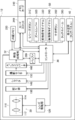
- the housing 14 has substantially the same structure as the housing of a general digital camera, and the photographing unit 20 shown in FIG. 3 and the control unit including the controller 30 and the image processing unit 32 are housed therein. ing.
- the photographing unit 20 is a device for photographing an image, and as shown in FIG. 3, the lens unit 110, the lens driving unit 120, the aperture unit 130, the shutter 140, the photographing sensor 150, and the A / D (Analog / Digital) converter. Has 160.
- the lens unit 110 includes a zoom lens 112 and a focus lens 114, and in the first embodiment, the zoom lens 112 is equipped with an anamorphic lens. Therefore, in the first embodiment, it is possible to shoot an image with a wide angle of view in the horizontal direction (for example, an angle of view with an aspect ratio of 2.35: 1).
- the lens is not limited to an anamorphic lens, and a photographic lens such as a wide-angle lens, an ultra-wide-angle lens, or a 360-degree lens may be used.
- the lens unit 110 may be configured to be interchangeable with another lens unit.
- the photographing unit 20 may include a plurality of lens units 110 having different angles of view from each other.
- the angle of view when the photographing unit 20 captures an image is determined according to the specifications of the lens unit 110 and the photographing sensor 150, and the image captured at that angle of view is the "reference image" of the present invention. Equivalent to.
- the aspect ratio of the reference image is a value corresponding to the above angle of view, and is, for example, 2.35: 1 when an anamorphic lens is used.
- the lens drive unit 120 includes a drive motor (not shown) and a drive mechanism (not shown), and moves the lens of the lens unit 110 along the optical axis.
- the aperture 130 adjusts the size of the opening according to the user's setting or automatically, and adjusts the amount of light passing through the opening.
- the shutter 140 blocks the transmitted light to the photographing sensor 150.
- the photographing sensor 150 is composed of, for example, a CCD (Charged Coupled Device) or a CMOS (Complementary Metal Oxide Semiconductor Image Sensor), and receives light from a subject via a lens unit 110 to form an image and obtains image data. Generate. Specifically, the photographing sensor 150 converts an optical signal received through a color filter into an electric signal by a light receiving element, amplifies the electric signal by an AGC (Auto Gain Controller), and analog image data from the amplified signal. To generate.
- a CCD Charge Coupled Device
- CMOS Complementary Metal Oxide Semiconductor Image Sensor
- the A / D converter 160 converts the analog image data generated by the photographing sensor 150 into digital image data.
- This digital image data corresponds to the data of the frame image constituting the reference image which is a moving image.
- the number of pixel data (that is, the number of pixels) constituting the digital image data is not particularly limited, but in the first embodiment, the number of pixels is 10 million or more, preferably the lower limit of the number of pixels is 60 million or more. It is good to be.
- the upper limit of the number of pixels in the first embodiment is preferably 1 billion or less, more preferably 500 million or less. If the number of pixels exceeds the lower limit, the visibility of the extracted image extracted from the reference image can be guaranteed. Further, if the number of pixels is less than the upper limit, the amount of pixel information of the reference image can be further reduced, so that the processing by the control unit (specifically, the image processing unit 32) is speeded up.
- the controller 30 can control each part of the photographing apparatus main body 12 according to the user's operation or automatically, for example, control the photographing unit 20 to cause the photographing unit 20 to take (acquire) a reference image. Further, the controller 30 can control the video processing unit 32 so that the video (specifically, the extracted video described later) is recorded on the recording medium. Further, the controller 30 is a lens driving unit so as to focus the focus of the lens unit 110 on the subject in the image based on the contrast of all or a part of the image indicated by the digital image data generated by the photographing unit 20. 120 can be controlled.
- the controller 30 can control the aperture unit 130 based on the brightness of all or a part of the image indicated by the digital image data generated by the photographing unit 20, and automatically adjust the exposure amount at the time of photographing. it can. Further, the controller 30 can control the lens driving unit 120 so as to automatically perform zoom (optical zoom) according to the operation of the user or according to the distance between the subject and the photographing device 10.
- zoom optical zoom
- the image processing unit 32 Under the control of the controller 30, the image processing unit 32 performs processing such as gamma correction, white balance correction, and scratch correction on the digital image data generated by the photographing unit 20, and further conforms to a predetermined standard. Compress in compression format. Then, the image processing unit 32 acquires a reference image from the compressed digital image data sequentially generated during shooting, and executes various processes on the acquired reference image. As an example of processing for the reference image, the image processing unit 32 can extract an extracted image (so-called crop image) smaller than the angle of view of the photographing unit 20 from the reference image.
- the image processing unit 32 can change the size of the range of the extracted image (hereinafter, referred to as the extraction range) in order to zoom (electronically zoom) the image of the subject in the extracted image.
- the size of the extraction range is the number of pixels of the extracted video (strictly speaking, the number of pixels in each of the vertical and horizontal directions of the extracted video).
- the control unit including the controller 30 and the video processing unit 32 is composed of one or a plurality of microcontrollers or processors.
- the control unit is composed of, for example, a CPU (Central Processing Unit) and a control program for causing the CPU to execute various processes.
- the above processors are not limited to this, and the above processors are FPGA (Field Programmable Gate Array), DSP (Digital Signal Processor), ASIC (Application Specific Integrated Circuit), GPU (Graphics Processing Unit), MPU (Micro- It may be configured by a Processing Unit) or another IC (Integrated Circuit), or may be configured by combining these.
- the functions of the entire control unit including the controller 30 and the video processing unit 32 may be configured by one IC (Integrated Circuit) chip. .. Further, the hardware configuration of each processor described above may be realized by an electric circuit (Circuitry) in which circuit elements such as semiconductor elements are combined.
- the housing 14 further houses a built-in memory 230 built in the photographing device main body 12, a memory card 240 that can be attached to and detached from the photographing device main body 12 via the card slot 260, and a buffer 250. ..
- the built-in memory 230 and the memory card 240 are recording media on which the above-mentioned extracted video is recorded, and are composed of a flash memory, a ferroelectric memory, or the like.
- the buffer 250 functions as a work memory of the controller 30 and the video processing unit 32, and is composed of, for example, a DRAM (Dynamic Random Access Memory) or a ferroelectric memory.
- various setting contents, shooting conditions, and the like are stored in the buffer 250.
- the recording medium does not have to be provided inside the photographing apparatus main body 12, and may be an external recording medium connected to the photographing apparatus main body 12 via the Internet. Further, the recording medium may be connected to the photographing apparatus main body 12 via a cable such as a USB (Universal Serial Bus) cable or HDMI (High-Definition Multimedia Interface) (registered trademark) or in a wireless format.
- a cable such as a USB (Universal Serial Bus) cable or HDMI (High-Definition Multimedia Interface) (registered trademark) or in a wireless format.
- a display device 40 is attached to the back surface of the housing 14.
- the display device 40 is composed of an LCD (Liquid Crystal Display), an organic EL (Organic Electroluminescence Display) display, an LED (Light Emitting Diode) display, electronic paper, or the like.
- Various images including the above-mentioned extracted images are displayed on the display device 40, and an operation screen for setting shooting conditions and selecting a mode is also displayed.
- the aspect ratio of the screen of the display device 40 is different from the aspect ratio of the angle of view, for example, 4: 3 or 16: 9, and the screen of the display device 40 has a higher angle of view. In comparison, the value corresponding to the horizontal width / vertical width is small.
- the housing 14 is provided with an operation unit 50, and the user performs various operations related to shooting through the operation unit 50.
- the operation unit 50 includes a release button 310, a zoom lever 320, a front operation dial 330, a rear operation dial 340, a cross button 350, and a touch wheel arranged on the housing 14. Includes 360 and the like.
- these devices transmit various control signals to the controller 30.
- the zoom lever 320 is operated, a control signal for changing the zoom magnification is transmitted to the controller 30 according to the operation, and the controller 30 moves the lens 112 in accordance with the control signal.
- the drive unit 120 is controlled.
- the display device 40 is a touch panel display and is also used as the operation unit 50.
- a control signal corresponding to the touch position is transmitted to the controller 30.
- an extraction mode selection screen (see FIG. 6), which will be described later, is displayed on the display device 40, the user selects one of the plurality of modes, and the corresponding mode selection buttons drawn on the screen are supported. Touch one button to do.
- a control signal for setting the selected mode is transmitted to the controller 30.
- the user can instruct the control unit to perform zoom processing or shutter processing (shooting processing) by touching the screen of the display device 40.
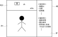
- the screen of the display device 40 is divided into three areas during shooting, and as shown in FIG. 4, the extracted image P1 is in the first area and the support image P2 is in the second area.
- Information IFs such as setting contents are displayed at the same time in the area 3.
- each of the extracted video P1, the support video P2, and the information IFs such as the setting contents will be described in detail.
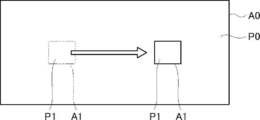
- the extracted image P1 is an image set to be smaller than the angle of view A0 at the angle of view A0 of the reference image P0, and is extracted (cut out) from the reference image P0.
- the reference video P0 is a high-quality video composed of 10 million or more (preferably 60 million or more) pixels
- the extracted video P1 extracted from the pixels is also a sufficiently high-quality video.
- the outer edge of the extracted image P1 has a rectangular shape, but the outer edge shape of the extracted image P1 is not particularly limited, and is square, parallelogram, trapezoidal, rhombic, circular or elliptical, triangular, or It may be a polygon of pentagon or more, or an indefinite shape.
- the extracted video P1 is extracted from the reference video P0 at any time by the video processing unit 32 during shooting, and is displayed in the first area on the screen of the display device 40 by the video processing unit 32. At this time, the extracted video P1 is displayed in a state in which the display size can be changed so as to fit in the first region while maintaining the aspect ratio constant.
- the extracted image P1 is displayed with the size of the angle of view A0 in the lateral direction increased when the anamorphic lens is used. This is because the image size is once compressed in the lateral direction of the angle of view A0 at the time of imaging by the photographing sensor 150, and the display size is returned to the original size when the extracted image P1 is displayed.
- the extracted video P1 is displayed in the lowermost region on the screen of the display device 40.
- the present invention is not limited to this, and for example, the extracted video P1 may be displayed in the uppermost region or the central region on the screen of the display device 40.
- the range of the extracted image P1 at the angle of view A0 that is, the extraction range A1 can be moved over time within the angle of view A0.
- “moving with time” means moving the extraction range A1 relative to the angle of view A0 so that the position of the extraction range A1 gradually changes, and the movement stops in the middle. It may include the case of (interruption).
- the movement of the extraction range A1 over time is realized by the video processing unit 32. Specifically, when the user selects one mode through the extraction mode selection screen shown in FIG. 6, the video processing unit 32 sets the extraction range A1 at an angle of view A0 along the movement path corresponding to the selected mode. Move within.
- One mode is a mode in which the extraction range A1 is moved so as to track the subject to be tracked (hereinafter, referred to as a tracking mode).
- the other mode is a mode in which the extraction range A1 is moved in a certain direction (hereinafter, referred to as a panning mode).
- the video processing unit 32 moves the extraction range A1 so as to track the subject to be tracked.
- the user specifies the image of the subject in the extracted image P1 by touching it on the screen.
- the video processing unit 32 sets a subject designated by the user as a tracking target. After that, the video processing unit 32 moves the extraction range A1 so that the subject to be tracked fits within the extraction range A1 as shown in FIG.
- the extracted image P1 showing the subject to be tracked can be constantly displayed on the display device 40. Further, the user does not have to move the photographing device 10 by himself / herself to track the subject, and therefore there is no manual change of the angle of view, and the image distortion (image blur, etc.) caused by the manual change of the angle of view is avoided. You can also do it. Such an effect is particularly effective when shooting at an angle of view when an anamorphic lens is used.
- the algorithm for searching the subject to be tracked within the angle of view A0 is not particularly limited.
- an image of a subject set as a tracking target is stored in the buffer 250 as a template image, and a known template matching technique is applied to compare the above template image with the reference image P0. Then, as a result of the comparison, the image of the portion matching the template image may be specified as the image of the subject to be tracked.
- the video processing unit 32 slides the extraction range A1 in a certain direction (for example, the lateral direction of the angle of view A0), that is, pans.
- a certain direction for example, the lateral direction of the angle of view A0
- the user sets the start position, the moving direction, the moving speed, and the like of the extraction range A1 on a setting screen (not shown).
- the video processing unit 32 automatically pans the extraction range A1 from the set start position in the set direction at the set speed.
- the panning mode when the panning mode is selected, it is possible to display on the display device 40 an image in which the shooting angle is continuously changed in a certain direction, so to speak, a panoramic image. Further, the user does not have to move the photographing device 10 by himself / herself to change the angle, and therefore there is no manual change of the angle of view, and the image distortion (image blur, etc.) caused by the manual change of the angle of view can be avoided. You can also. Such an effect is particularly effective when shooting at an angle of view when an anamorphic lens is used.
- the initially set contents are usually adopted, but the user is displayed on a setting screen (not shown).
- the aspect ratio of the extraction range A1 is the aspect ratio of the extracted video P1, and strictly speaking, it is the ratio of the number of pixels in each of the aspect ratios.
- the area ratio of the extraction range A1 is the ratio of the area of the extraction range A1 to the angle of view A0.
- the moving speed of the extraction range A1 is the number of pixels that the moving extraction range A1 passes through in a unit time when the angle of view A0 is divided in pixel units.
- an instruction by the user is received through the operation unit 50 while the extraction range A1 is moving, and the size, the moving speed, the moving direction, the moving position, and the like of the extraction range A1 are changed based on the instruction.
- the size may be changed by operating the front operation dial 330, and the moving speed may be changed by operating the rear operation dial 340.
- the moving direction may be changed by operating the cross button 350, and the moving position may be changed by the touch panel of the display device 40.
- the user can intuitively change various setting contents related to the extraction range A1 in real time according to the moving situation of the extraction range A1.
- the device operated when changing the setting content of the extraction range A1 is not limited to the above-mentioned correspondence, and for example, the size of the extraction range A1 may be changed based on the operation of the touch wheel 360. ..
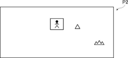
- the support image P2 is an image based on the positional relationship between the angle of view A0 and the extraction range A1 during shooting, and is displayed for the user to grasp the position of the extraction range A1 within the angle of view A0 during shooting.
- the support video P2 is displayed on the display device 40 by the video processing unit 32. Specifically, the image processing unit 32 recognizes the position and size of the extraction range A1 during shooting, generates the support image P2 based on the information, and displays it on the display device 40.
- the support image P2 is an image including the extracted image P1 as shown in FIG. 9, and in the first embodiment, the reference image P0 (strictly speaking, the reference image P0 whose display size is reduced while maintaining the aspect ratio). ) Is composed of the whole.
- the support video P2 is a video in which the position of the extracted video P1 in the support video P2 is specified. Specifically, as shown in FIG. 9, the extracted video P1 is surrounded by a frame. There is.
- the mode for specifying the position of the extracted video P1 in the support video P2 may be a mode other than the mode surrounded by a frame. For example, in the support video P2, only the display color of the extracted video P1 may be changed to the highlight color, or an instruction mark such as a cursor may be displayed in the vicinity of the extracted video P1 in the support video P2. Further, in the support video P2, the display color of the region other than the extracted video P1 may be translucent or gray to emphasize the extracted video P1.
- the position of the extraction image P1 in the support image P2 also changes in conjunction with it. If the size, aspect ratio, and position of the extraction range A1 are changed during movement, the size, aspect ratio, and position of the extracted image P1 in the support image P2 also change according to the changed settings. To do.
- the support video P2 described above is generated at any time by the video processing unit 32 based on the positional relationship between the angle of view A0 and the extraction range A1 during shooting, and is generated by the video processing unit 32 on the screen of the display device 40. It is displayed in the area of. At this time, the support image P2 is displayed in a state in which the display size can be changed so as to fit in the second area while maintaining the aspect ratio constant.
- the support image P2 has the same aspect ratio as the reference image P0 (that is, the angle of view A0).
- the reference image P0 is extended in the horizontal direction of the angle of view A0 to form a horizontally long image with an aspect ratio of 2.35: 1, and the reference image P0 is displayed as the support image P2. Displayed on the device 40.
- the aspect ratio of the display screen on the display device 40 is often different from the aspect ratio of the support image P2 (for example, 4: 3 or 16: 9).
- the support image P2 is displayed on the display device 40, a space (margin) is often generated at a position adjacent to the support image P2 in the vertical direction of the display screen.
- the extracted video P1 and the support video P2 can be simultaneously fitted on the display device 40 and displayed well.
- the support image P2 is displayed at a position directly above the extracted image P1, but the present invention is not limited to this, and the support image P2 is displayed below the extracted image P1. It may be displayed.
- the information IF such as the setting contents is information about at least one of the reference video P0 and the extracted video P1, and in the first embodiment, it is character information about each of the reference video P0 and the extracted video P1.
- the information IF such as the setting contents is displayed on the display device 40 in cooperation with the controller 30 and the video processing unit 32. Specifically, the controller 30 reads the setting contents and shooting conditions from the buffer 250, and the video processing unit 32 displays the information IF such as the setting contents on the display device 40 based on the information read by the controller 30. indicate.
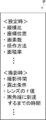
- the information IFs such as the setting contents are the setting contents (contents belonging to the category described as "at the time of setting” in FIG. 10) for each of the reference image P0 and the extracted image P1 and during shooting. (Information belonging to the category described as "at the time of shooting” in FIG. 10).
- the information displayed as the information IF such as the setting contents is not particularly limited, but as an example, the aspect ratio and the number of pixels of the extracted image P1, the position and area ratio of the extraction range A1, and the moving distance of the extraction range A1 during movement are used.
- Conditions for example, exposure conditions, lens f-number, ISO sensitivity, white balance, etc.), number of pixels in the extraction area (4K, Full HD [High Definition], etc.), frame rate at the time of moving image shooting, etc. Be done.
- the position of the extraction range A1 is a representative position of the extraction range A1 (for example, the center position or the position of four vertices), and the reference position set at the angle of view A0 (for example, the upper left vertex position of the angle of view A0). Is expressed as the coordinates when the origin is.
- the moving distance of the extraction range A1 during movement is a relative value (ratio) when the total moving distance of the extraction range A1 from the start of movement is obtained in pixel units and, for example, the length of the angle of view A0 in the moving direction is used as a reference. ).
- the estimated time until the moving extraction range A1 reaches the end of the angle of view A0 is the time required for the extraction range A1 to move to the end of the angle of view A0, from the end of the extraction range A1 to the end of the angle of view A0. It is obtained from the distance of and the moving speed of the extraction range A1.
- the setting operation method of the extraction range A1 is information indicating which device of the operation unit 50 is to be operated when "a certain content" is set with respect to the extraction range A1.
- the information IF (specifically, the position of the extraction range A1 etc.) such as the displayed setting contents changes in conjunction with it. Further, when the size and aspect ratio of the extraction range A1 are changed during the movement, the information IF such as the setting contents is updated according to the changed setting contents.
- the information IF such as the setting contents is displayed on the display device 40 together with the extracted video P1 and the support video P2 by the video processing unit 32 during shooting.
- information IFs such as setting contents are displayed at positions (for example, positions adjacent to the right) side by side with each of the extracted video P1 and the support video P2.
- an information IF such as setting contents may be displayed at an upper position or a lower position of the extracted image P1 or an upper position or a lower position of the support image P2.
- a plurality of areas on the screen of the display device 40 on which information IFs such as setting contents are displayed may be provided, information on the reference image P0 is displayed in one of the areas, and information on the extracted image P1 is displayed in another area. Information may be displayed.
- FIGS. 11 and 12 show the flow of the display flow by the photographing apparatus 10.
- the display method of the present invention is adopted.
- each step shown in FIGS. 11 and 12 corresponds to a component of the display method of the present invention.
- the display method of the present invention is adopted, and the recording step described later is executed. That is, in the above display flow, the video recording method of the present invention is adopted.
- the user activates the photographing device 10.
- the controller 30 executes the setting process (S001).
- the extraction range A1 is set within the angle of view A0 based on a preset initial value or a content instructed by the user.
- the photographing step corresponds to an acquisition step of acquiring a reference image P0 which is a moving image, and in the first embodiment, it is a step of photographing the reference image P0 at an angle of view A0 when an anamorphic lens is used.
- the video processing unit 32 executes the extraction process under the control of the controller 30 (S003).
- the video processing unit 32 extracts the video of the extraction range A1 set in the setting step, that is, the extraction video P1 from the reference video P0.
- the image processing unit 32 executes a first display step of displaying the extracted image P1 on the display device 40 and a second display step of displaying the support image P2 described above on the display device 40 in accordance with the extraction of the extracted image P1. (S004).
- the second display step is executed during the execution of the first display step.
- the extracted image P1 and the support image P2 are simultaneously displayed on the display device 40 during shooting.
- the extracted image P1 is displayed by increasing the size of the angle of view A0 in the lateral direction when the anamorphic lens is used in the first display step. Further, in the first embodiment, in the first display step, the extracted video P1 is displayed in a state in which the display size of the extracted video P1 can be changed while maintaining the aspect ratio of the extracted video P1 constant.
- the support image P2 in which the position of the extracted image P1 in the support image P2 is specified specifically, the support image P2 in which the portion of the extracted image P1 is surrounded by a frame as shown in FIG. Is displayed.
- the support video P2 is displayed in a state where the display size of the support video P2 is changed in accordance with the change in the display size of the extracted video P1.
- the third display step of displaying the information IF such as the setting contents on the display device 40 is further executed.
- information IFs such as the extracted image P1, the support image P2, and the setting contents are simultaneously displayed on the display device 40.
- the execution of the recording process is started with this as an opportunity (S005).
- the extracted video P1 is recorded by the video processing unit 32 in the built-in memory 230 or the memory card 240 as a recording medium.
- the video to be recorded is limited to the extracted video P1, and the other videos, that is, the reference video P0 and the support video P2 are discarded without being recorded. As a result, the amount of recording capacity used can be further reduced.
- the present invention is not limited to this, and one or both of the reference video P0 and the support video P2 may be recorded together with the extracted video P1.
- the moving process is executed by the image processing unit 32 (S007).
- the extraction range A1 moves along the moving path according to the mode selected by the user among the tracking mode and the panning mode described above within the angle of view A0. More specifically, when the tracking mode is selected, the extraction range A1 is moved within the angle of view A0 so that the subject to be tracked set by the user falls within the extraction range A1.
- the extraction range A1 slides (panning) based on the start position, the moving direction, and the moving speed set by the user.
- the video processing unit 32 executes the first display step, the second display step, and the third display step according to the movement of the extraction range A1 (S008).
- the first display step the extracted video P1 is displayed while the extraction range A1 is moving.
- the second display step the support image P2 is displayed so that the position of the extracted image P1 in the support image P2 changes
- the information IF such as the setting contents is displayed according to the movement of the extraction range A1. Update and display.
- step S008 as in step S005, the second display step is executed during the execution of the first display step, and the third display step is executed during the execution of both the first display step and the second display step.
- the video processing unit 32 executes the recording step so as to record the extracted video P1 while the extraction range A1 is moving by the moving step (S009).
- the above-mentioned first to third display steps and recording steps are repeated until the user gives an instruction to end shooting (S010), and the instruction to end shooting is issued.
- the operation of instructing the end of shooting by the user is not particularly limited, but for example, the operation of pressing the release button 310 again may be the operation of instructing the end of shooting.
- the user refers to the position, size, moving speed, and moving direction of the extraction range A1 (hereinafter, referred to as "position of the extraction range A1", etc. "during the execution of the moving process.
- position of the extraction range A1 the position of the extraction range A1 and the like are reset based on the user's instruction received during the execution of the moving process.
- step S007 each of the moving step, the first to third display steps, and the recording step is repeatedly executed.
- the moving process after the position of the extraction range A1 is reset, at least one of the positions of the extraction range A1 is changed based on the instruction received by the user during the execution of the moving process, and then the extraction range A1 is changed. To move.
- the information IFs such as the extraction image P1, the support image P2, and the setting contents based on the extraction range A1 whose position and the like are changed are displayed on the display device 40. Will be done. Specifically, in the first display step, the extracted video P1 after the position of the extraction range A1 is changed is displayed. In the second display step, the support image P2 in which the position of the extracted image P1 in the support image P2 is the changed position is displayed. In the third display step, the information IF such as the setting contents is updated and displayed according to the change of the position or the like of the extraction range A1.
- the video processing unit 32 appropriately executes the determination process (S013).
- the determination step is executed during the execution of the moving step, and in the determination step, between the end of the angle of view A0 and the end of the extraction range A1 (strictly speaking, the end closer to the end of the angle of view A0). Determine if the distance is less than the threshold.
- the video processing unit 32 executes the warning step (S015) and warns the user.
- the warning step S015
- the warning method in the warning process is not particularly limited, but for example, a warning message is displayed on the display device 40, or the outer edge frame of the extracted image P1 is set to a predetermined color (specifically, red or the like). It can be changed.
- the extracted image P1 smaller than the angle of view A0 can be extracted from the reference image P0, and the extraction range A1 can be moved within the angle of view A0. Further, while the extraction range A1 is moving, the user can confirm the extracted video P1 by displaying the extracted video P1 on the display device 40. At this time, it is preferable that the position of the extraction range A1 within the angle of view A0 can be grasped. Therefore, in the first embodiment, the support image P2 as an interface representing the position of the extraction range A1 within the angle of view A0 is displayed on the display device 40 together with the extraction image P1.
- the first embodiment when a change instruction by the user is received during the execution of the moving step, at least one of the position, size, moving speed, and moving direction of the extraction range A1 is changed based on the instruction. .. In such a case, the effect that the user can grasp the position of the extraction range A1 is more remarkable.
- the support video P2 includes the extracted video P1, and the position of the extracted video P1 in the support video P2 is specified (for example, the extracted video P1 is surrounded by a frame). Is displayed. As a result, the user can more easily grasp the position of the extraction range A1.
- information regarding at least one of the reference video P0 and the extracted video P1 that is, the information IF such as the setting contents is displayed on the display device 40 at the same time as the extracted video P1 and the support video P2.
- the user can confirm various information indicated by the information IF such as the setting contents, and can know more detailed information about the position of the extraction range A1 specified from the support video P2.
- the support image P2 is composed of the entire reference image P0, and in the second display step, the support image P2 is displayed on the display device 40 in a state in which the display size of the support image P2 can be changed.
- a support image different from the support image P2 according to the first embodiment for example, support images P21 and P22 shown in FIGS. 13 and 14 are displayed.
- This embodiment will be referred to as a second embodiment, and will be described below with reference to FIGS. 13 to 15.
- FIGS. 13 and 14 show a screen example of the display device 40 according to the second embodiment, and correspond to FIG.
- the user selects one of the two display methods, and the support image is displayed on the display device 40 by the selected display method. That is, the second display step in the second embodiment is executed according to the display method selected by the user among the first display method and the second display method.
- the selection screen shown in FIG. 15 may be displayed on the display device 40, and the user may touch one of the display methods on the screen to select the display method.
- the support image P21 composed of the entire reference image P0 is displayed on the display device 40.
- the aspect ratio and display size of the support image P21 can be changed.
- the support image P21 in the second display step when the first display method is selected, can be displayed in a state in which the aspect ratio and display size of the support image P21 can be changed.
- the support image P21 can be displayed by crushing it in the vertical direction to reduce the display size.
- the degree of freedom in displaying the support image P21 is higher than that in the first embodiment. That is, in the second display step when the first display method is adopted, the support image P21 is displayed in a state where the aspect ratio and the display size of the support image P21 are changed in accordance with the change in the display size of the extracted image P1.
- the aspect ratio and display size of the support image P21 are adjusted to fit the space in order to display the support image P21 in the extra space. Can be changed freely.
- the support image P22 composed of a part of the reference image P0 is displayed on the display device 40.
- the support image P22 is displayed in a state in which the display size can be changed while maintaining the aspect ratio constant. That is, in the second display step when the second display method is selected, the display size of the support image P22 is changed while maintaining the aspect ratio of the support image P22 as the display size of the extracted image P1 is changed. It can be displayed in the state of.
- the user can freely set the range of the support image P22 in the reference image P0 (specifically, the range displayed as the support image P22) by operating the operation unit 50 or the like. It can be specified and the specified range can be changed freely. That is, in the second display step when the second display method is selected, the support image P22 can be displayed while moving the range of the support image P22 in the reference image P0.
- a method of designating the range of the support image P22 in the reference image P0 various methods such as button operation or touch panel operation can be mentioned, but in the second embodiment, the method using the auxiliary image Ps described later is used. Will be done.
- the image in the range specified by the user in the reference image P0 is set as the support image P22, and the aspect ratio of the support image P22 is maintained.
- the display size of the support video P22 can be changed. For example, in the reference image P0, only the range necessary for displaying as the support image P22 is specified, and then the display size of the support image P22 is appropriately adjusted. By doing so, the display space of the support image P22 in the display device 40 can be made smaller.
- the range instruction video P3 which is a video showing the range of the support video P22 in the reference video P0, is displayed together with the extracted video P1 and the support video P22. It is displayed on the device 40.
- the range instruction video P3 is composed of a reduced reference video P0 and auxiliary video Ps displayed superimposed on the reference video P0.
- the auxiliary video Ps indicates a portion corresponding to the support video P22 in the reference video P0.
- auxiliary video Ps can be moved by the user performing a touch-and-drag operation on the screen. Then, by moving the auxiliary video Ps, the range of the support video P22 in the reference video P0 can be changed.
- a step of displaying the range indication video P3 described above (hereinafter referred to as a fourth display step) is a first step. It is executed during all executions of the third display process. That is, in the second display format, the extracted image P1, the support image P22, the information IF such as the setting contents, and the range instruction image P3 are all displayed on the display device 40 at the same time.
- the second display method is selected as described above, the user can freely determine the range of the support video P22 by operating the auxiliary video Ps. Further, by confirming the support image P22 and the range instruction image P3, the position of the extraction range A1 within the angle of view A0 can be grasped.
- the display of the range instruction image P3 (that is, the execution of the fourth display step) is not always necessary, and the display of the range instruction image P3 is omitted and only the support image P22 is displayed. May be displayed.
- the extracted video P1, the support video P2, and the information IFs such as the setting contents are all displayed on the display device 40 of the same shooting device 10.
- the extracted video P1 and the support video P2 are displayed on different display devices.
- This embodiment will be referred to as a third embodiment, and will be described below with reference to FIGS. 16 to 18.
- the third embodiment relates to a display method using the photographing system S shown in FIG. That is, the display method according to the third embodiment of the present invention is realized by the photographing system S.
- the photographing system S is composed of a photographing device 10X and an external monitor.
- the basic configuration of the photographing device main body 12X according to the third embodiment is substantially the same as the basic configuration of the photographing device main body 12 according to the first embodiment.
- the photographing device main body 12X includes a first display device 410 configured by a touch panel display or the like, and is connected to a second display device 420 which is an external monitor.
- the second display device 420 is composed of a display device such as a liquid crystal monitor, a recorder with a monitor, an information processing terminal with a monitor such as a laptop personal computer, a smartphone or a tablet terminal, and the like.
- the photographing device 10X and the second display device 420 according to the third embodiment are connected by a wired system or a wireless system.
- the display device 400 for displaying images includes the first display device 410 and the second display device 420, which are separate devices from each other. Further, in the third embodiment, the video processing unit 32 of the photographing device transmits a video signal to each display device. As a result, as shown in FIG. 17, the first display device 410 displays the extracted image P1, and the second display device 420 displays the support image P2.
- the step of displaying the support image P2 on the second display device 420 (that is, that is) during the execution of the step of displaying the extracted image P1 on the first display device 410 (that is, the first display step).
- the second display step is executed.
- the second display device 420 may display an image corresponding to the display format selected by the user among the two types of support images P21 and P22 described in the second embodiment.
- the information IF such as the setting contents is displayed on the second display device 420 together with the support image P2.
- the step of displaying the information IF such as the setting contents on the second display device 420 (that is, the third display step) is provided, and the third display step includes the first display step and the second display step. Performed during both executions of the display process.
- a part of the information IF such as the setting contents for example, shooting conditions (for example, exposure conditions, lens f-number, ISO sensitivity, white balance, etc.) is displayed on the first display device 410 as shown in FIG. You may.
- the orientation detector 60 is mounted on the photographing apparatus main body 12X according to the third embodiment.
- the orientation detector 60 is composed of, for example, an acceleration sensor or the like, and detects the movement when the orientation of the photographing device 10X changes, for example, when the photographing device 10X is vertically and horizontally inverted.
- the first display device 410 when the user flips the photographing device 10X vertically and horizontally during the execution of the first display step, that is, while the extracted image P1 is displayed on the first display device 410, the first display device 410 is vertically and horizontally inverted. It is inverted and the display direction of the extracted image P1 is rotated by 90 degrees as shown in FIG.
- the controller 30 controls the video processing unit 32 according to the detection result.
- the image processing unit 32 generates the support image P2 that is vertically and horizontally inverted from the state before the orientation detector 60 detects the vertical and horizontal inversion of the photographing device 10X. Then, the video processing unit 32 transmits the video signal to the second display device 420.
- the vertically and horizontally inverted support image P2 is displayed on the second display device 420 as shown in FIG.
- the display direction of the support image P2 in conjunction with the change in the display direction of the extracted image P1 in this way, even if the first display device 410 is vertically and horizontally inverted, the extracted image P1 and the support image P2 can be combined. It becomes easier for the user to understand the correspondence.
- the information IF such as the setting contents is displayed on the second display device 420.
- the orientation detector 60 inverts the photographing device 10X vertically and horizontally. The display orientation does not change even after detection. That is, in the third display step, the information IF such as the setting contents is displayed on the second display device 420 in a state where the display orientation is maintained before and after the vertical / horizontal inversion of the first display device 410. Even when the display orientation of the extracted video P1 is reversed vertically and horizontally in this way, the information IF such as the setting content which is the character information is displayed in the normal orientation, so that the user can easily check the information IF such as the setting content. ..
- the moving image is a moving image.
- the moving image means a set of a plurality of images (frame images) continuously captured at a constant frame rate.
- the extracted video recorded on the recording medium is a moving image.
- the extracted video recorded on the recording medium may be a still image.
- the control unit including the controller 30 and the image processing unit 32 uses the still image acquired in the acquisition process (specifically, the shooting process) as the reference image P0.
- the control unit displays the still image, which is the reference image P0, on the display device 40 as the support image P2. Further, the control unit sets the extraction range A1 corresponding to the subject in the reference image P0, and displays the extraction image P1 reflected in the extraction range A1 on the display device 40. Then, when the recording process is instructed by the user and the recording process is executed, the control unit executes the recording of the still image instead of shooting the moving image, and the extracted video P1 which is the still image is recorded on the memory card 240 or the like. It may be recorded on a recording medium.
- the present invention is not limited to this, and the image acquisition process may be, for example, a process of acquiring an image for moving image editing as a reference image from the outside.
- the reference video may be acquired by downloading a moving image file of the reference video from an external data distribution device (server).
- the reference video may be acquired by reading the video to be edited from the recording medium in which the moving image file is recorded.
- a digital camera is mentioned as an example of the photographing device, but the present invention is not limited to this, and for example, a mobile terminal such as a mobile phone, a smartphone, or a tablet PC with an imaging optical system may be used. .. Further, the above-mentioned anamorphic lens may be a lens unit externally attached to the above-mentioned photographing optical system of the mobile terminal.
Abstract
画角内を移動する抽出範囲の位置をユーザに把握させるための表示方法及び映像記録方法を提供する。 本発明の表示方法は、動画像である基準映像を取得する取得工程と、基準映像の画角において画角よりも小さく設定された抽出映像を、基準映像から抽出する抽出工程と、抽出映像の抽出範囲を経時的に移動させる移動工程と、抽出映像を表示装置に表示する第1表示工程と、画角と抽出範囲との位置関係に基づく支援映像を、表示装置に表示する第2表示工程と、を備え、第1表示工程の実行中に第2表示工程が実行される。
Description
本発明は、映像を表示する表示方法、及び、映像を記録する映像記録方法に関する。
映像を撮影する撮影装置の中には、特許文献1及び2に記載された撮影装置のように、撮影された映像の画角の一部の映像を抽出し(切り出し)、その抽出映像を表示するものが存在する。
特許文献1及び2に記載された撮影装置は、画角内における抽出領域の位置等を所定の速度にて変化させる機能を備える。この機能を利用すれば、例えば、撮影中に撮影装置を人手で動かさなくとも、映像中の被写体を追尾したり、記録映像のアングルを一定方向にスライド移動させたりすることができる。
特許文献1及び2に記載された撮影装置は、画角内における抽出領域の位置等を所定の速度にて変化させる機能を備える。この機能を利用すれば、例えば、撮影中に撮影装置を人手で動かさなくとも、映像中の被写体を追尾したり、記録映像のアングルを一定方向にスライド移動させたりすることができる。
抽出範囲を移動させながら抽出範囲内の映像を表示する場合には、画角内のどの範囲が抽出されているのかをユーザが把握できるように、画角内における抽出範囲の位置を確認できることが求められている。
しかし、特許文献1及び2に記載された撮影装置を用いた映像の表示方法では、画角内を移動している抽出範囲内の映像が表示されるものの、表示された映像だけでは抽出範囲の位置を把握することが困難である。
しかし、特許文献1及び2に記載された撮影装置を用いた映像の表示方法では、画角内を移動している抽出範囲内の映像が表示されるものの、表示された映像だけでは抽出範囲の位置を把握することが困難である。
本発明は、上記の事情に鑑みてなされたものであり、上記従来技術の問題点を解決し、画角内を移動する抽出範囲の位置をユーザに把握させるための表示方法、及び、その表示方法を採用した映像記録方法を提供することを目的とする。
上記の目的を達成するために、本発明の表示方法は、基準映像を取得する取得工程と、基準映像の画角において画角よりも小さく設定された抽出映像を、基準映像から抽出する抽出工程と、抽出映像の抽出範囲を経時的に移動させる移動工程と、抽出映像を表示装置に表示する第1表示工程と、画角と抽出範囲との位置関係に基づく支援映像を、表示装置に表示する第2表示工程と、を備え、第1表示工程の実行中に第2表示工程が実行されることを特徴とする。
上述した本発明の表示方法によれば、抽出映像の表示中に、画角と抽出範囲との位置関係に基づく支援映像を表示することにより、画角内を移動する抽出範囲の位置をユーザに把握させることができる。
上述した本発明の表示方法によれば、抽出映像の表示中に、画角と抽出範囲との位置関係に基づく支援映像を表示することにより、画角内を移動する抽出範囲の位置をユーザに把握させることができる。
また、本発明の表示方法において、支援映像は、抽出映像を含み、第2表示工程では、支援映像中の抽出映像の位置が特定された支援映像を表示してもよい。
また、本発明の表示方法は、基準映像及び抽出映像のうちの少なくとも一つに関する情報を表示装置に表示する第3表示工程をさらに備えてもよい。この場合、第1表示工程及び第2表示工程の両方の実行中に、第3表示工程が実行されると、より好ましい。
また、本発明の表示方法において、第1表示工程では、抽出映像の表示サイズを変更可能な状態で抽出映像を表示し、第2表示工程では、支援映像の縦横比及び支援映像の表示サイズを変更可能な状態で支援映像を表示してもよい。
この場合、第1表示工程では、抽出映像の縦横比を一定に維持しながら抽出映像の表示サイズを変更可能な状態で抽出映像を表示し、第2表示工程では、抽出映像の表示サイズに伴って、支援映像の表示サイズを変更した状態で支援映像を表示してもよい。
この場合、第1表示工程では、抽出映像の縦横比を一定に維持しながら抽出映像の表示サイズを変更可能な状態で抽出映像を表示し、第2表示工程では、抽出映像の表示サイズに伴って、支援映像の表示サイズを変更した状態で支援映像を表示してもよい。
あるいは、上記の表示方法において、第2表示工程では、抽出映像の表示サイズの変更に伴って、基準映像における一部分の映像を示す支援映像を、支援映像の縦横比を一定に維持しながら支援映像の表示サイズを変更した状態で表示してもよい。
また、本発明の表示方法において、第2表示工程は、第1表示方式及び第2表示方式のうち、ユーザによって選択された表示方式に応じて実行され、第1表示方式が選択された場合、第2表示工程では、支援映像の縦横比及び支援映像の表示サイズを変更可能な状態で支援映像を表示し、第2表示方式が選択された場合、第2表示工程では、基準映像における一部分の映像を示す支援映像を、支援映像の縦横比を一定に維持しながら支援映像の表示サイズを変更可能な状態で表示してもよい。
また、取得工程は、画角にて基準映像を撮影する撮影工程であってもよい。この場合、撮影工程では、アナモフィックレンズを用いて画角にて基準映像を撮影し、第1表示工程では、抽出映像を、アナモフィックレンズを用いた画角の横方向におけるサイズを伸ばして表示してもよい。
また、本発明の表示方法において、移動工程は、撮影工程の実行中に実行され、移動工程では、移動工程の実行中に受け付けたユーザによる指示に基づいて、抽出範囲の位置、サイズ、移動速度及び移動方向のうちの少なくとも一つを変更してもよい。
また、本発明の表示方法において、移動工程では、ユーザにより設定された追尾対象の被写体が抽出範囲内に入るように抽出範囲を画角内で移動させてもよい。
また、表示装置は、互いに別装置である第1表示装置及び第2表示装置を含んでもよい。この場合、第1表示装置は、第1表示装置に抽出映像を表示し、第2表示装置は、第2表示装置に支援映像を表示してもよい。
また、本発明の表示方法は、基準映像及び抽出映像のうちの少なくとも一つに関する文字情報を、第2表示装置に表示する第3表示工程を備えてもよい。この場合、第1表示工程及び第2表示工程の両方の実行中に第3表示工程が実行され、第1表示工程中に第1表示装置を縦横反転させた場合には、第2表示工程では、縦横反転させた支援映像を第2表示装置に表示し、第3表示工程では、表示向きが維持された文字情報を第2表示装置に表示してもよい。
また、本発明の表示方法は、移動工程の実行中に、画角の端と抽出範囲の端との間の距離が閾値未満であるか否かを判定する判定工程と、距離が閾値未満である場合には、ユーザに対して警告を行う警告工程とを備えてもよい。
また、本発明によれば、上述の表示方法を採用し、且つ、抽出映像を記録媒体に記録する記録工程を備える映像記録方法を提供することができる。
また、本発明は、プロセッサを有する映像表示用の装置であって、プロセッサが、基準映像を取得する取得工程と、基準映像の画角において画角よりも小さく設定された抽出映像を、基準映像から抽出する抽出工程と、抽出映像の抽出範囲を経時的に移動させる移動工程と、抽出映像を表示装置に表示する第1表示工程と、画角と抽出範囲との位置関係に基づく支援映像を、表示装置に表示する第2表示工程と、を実行し、第1表示工程の実行中に第2表示工程を実行するように構成された装置を提供する。
本発明の表示方法及び映像記録方法によれば、画角内を移動する抽出範囲の位置をユーザに把握させることが可能である。
以下、本発明の好適な実施形態(第1実施形態~第4実施形態)について、添付の図面を参照しながら詳細に説明する。ただし、以下に説明する実施形態は、本発明の理解を容易にするために挙げた一例に過ぎず、本発明を限定するものではない。すなわち、本発明は、その趣旨を逸脱しない限りにおいて、以下に説明する実施形態から変更又は改良され得る。また、本発明には、その等価物が含まれる。
<<第1実施形態>>
本発明の第1実施形態は、図1及び2に示す撮影装置10を用いる表示方法に関する。すなわち、本発明の第1実施形態に係る表示方法は、撮影装置10によって実現される。
本発明の第1実施形態は、図1及び2に示す撮影装置10を用いる表示方法に関する。すなわち、本発明の第1実施形態に係る表示方法は、撮影装置10によって実現される。
[撮影装置の基本構成]
撮影装置10の基本構成について、図1~3を参照しながら説明する。
撮影装置10の基本構成について、図1~3を参照しながら説明する。
撮影装置10は、携帯可能なデジタルカメラであり、図1及び2に示す外観を有し、静止画像及び動画像を撮影する。また、撮影装置10は、撮影した画像(映像)を表示し、且つ、映像を記録する機能を有する。本明細書では、撮影装置10の機能のうち、動画像である映像をリアルタイムに撮影する機能について主に説明する。
撮影装置10は、撮影装置本体12と筐体14とによって構成されている。撮影装置本体12は、撮影装置10のうち、筐体14を除く部分である。筐体14は、一般的なデジタルカメラの筐体と略同じ構造であり、その内部には、図3に示す撮影部20、並びに、コントローラ30及び映像処理部32を含む制御部等が収容されている。
撮影部20は、映像を撮影する機器であり、図3に示すように、レンズユニット110、レンズ駆動部120、絞り部130、シャッタ140、撮影センサ150、及びA/D(Analog/Digital)コンバータ160を有する。
レンズユニット110は、ズームレンズ112及びフォーカスレンズ114を有し、第1実施形態では、ズームレンズ112がアナモフィックレンズを搭載している。そのため、第1実施形態では、横方向に広い画角(例えば、縦横比2.35:1の画角)で映像を撮影することが可能である。ただし、アナモフィックレンズに限定されず、広角レンズ、超広角レンズ及び360度レンズ等の撮影レンズが用いられてもよい。また、レンズユニット110は、他のレンズユニットに交換可能に構成されてもよい。また、撮影部20は、互いに画角が異なる複数のレンズユニット110を備えてもよい。
ここで、撮影部20が映像を撮影する際の画角は、レンズユニット110及び撮影センサ150の仕様等に応じて決まり、その画角で撮影される映像は、本発明の「基準映像」に相当する。基準映像の縦横比(アスペクト比)は、上記の画角に対応した値となり、アナモフィックレンズが用いられる場合には、例えば2.35:1となる。
ここで、撮影部20が映像を撮影する際の画角は、レンズユニット110及び撮影センサ150の仕様等に応じて決まり、その画角で撮影される映像は、本発明の「基準映像」に相当する。基準映像の縦横比(アスペクト比)は、上記の画角に対応した値となり、アナモフィックレンズが用いられる場合には、例えば2.35:1となる。
レンズ駆動部120は、不図示の駆動モータと、不図示の駆動機構とによって構成され、レンズユニット110のレンズを光軸に沿って移動させる。
絞り部130は、ユーザの設定に応じて、あるいは自動的に開口部の大きさを調整し、開口部を通過する光の量を調整する。
シャッタ140は、撮影センサ150への透過光を遮断する。
絞り部130は、ユーザの設定に応じて、あるいは自動的に開口部の大きさを調整し、開口部を通過する光の量を調整する。
シャッタ140は、撮影センサ150への透過光を遮断する。
撮影センサ150は、例えばCCD(Charged Coupled Device)又はCMOS(Complementary Metal Oxide Semiconductor Image Sensor)等で構成されており、レンズユニット110を介して被写体からの光を受光して結像し、画像データを生成する。具体的には、撮影センサ150は、カラーフィルタを通じて受光した光信号を受光素子にて電気信号に変換し、その電気信号をAGC(Auto Gain Controller)によって増幅し、増幅後の信号からアナログ画像データを生成する。
A/Dコンバータ160は、撮影センサ150で生成されたアナログ画像データをデジタル画像データに変換する。このデジタル画像データは、動画像である基準映像を構成するフレーム画像のデータに該当する。
なお、デジタル画像データを構成する画素データの数(すなわち、画素数)は、特に限定されないが、第1実施形態では画素数が1000万以上であり、好ましくは、画素数の下限が6000万以上であるとよい。また、第1実施形態における画素数の好ましい上限は、10億以下であり、より好ましくは5億以下である。画素数が下限を上回っていれば、基準映像から抽出される抽出映像の視認性が担保できる。また、画素数が上限を下回っていれば、基準映像の画素情報量をより少なくすることができるため、制御部(具体的には、映像処理部32)による処理が高速化する。
なお、デジタル画像データを構成する画素データの数(すなわち、画素数)は、特に限定されないが、第1実施形態では画素数が1000万以上であり、好ましくは、画素数の下限が6000万以上であるとよい。また、第1実施形態における画素数の好ましい上限は、10億以下であり、より好ましくは5億以下である。画素数が下限を上回っていれば、基準映像から抽出される抽出映像の視認性が担保できる。また、画素数が上限を下回っていれば、基準映像の画素情報量をより少なくすることができるため、制御部(具体的には、映像処理部32)による処理が高速化する。
コントローラ30は、ユーザの操作に従って、あるいは自動的に撮影装置本体12の各部を制御し、例えば、撮影部20を制御して撮影部20に基準映像を撮影(取得)させることができる。また、コントローラ30は、映像(詳しくは、後述する抽出映像)が記録媒体に記録されるように映像処理部32を制御することができる。また、コントローラ30は、撮影部20によって生成されたデジタル画像データが示す画像の全体又は一部のコントラスト等に基づいて、レンズユニット110の焦点を画像中の被写体に合焦させるようにレンズ駆動部120を制御することができる。また、コントローラ30は、撮影部20によって生成されたデジタル画像データが示す画像の全体又は一部の輝度に基づいて、絞り部130を制御し、撮影時の露光量を自動的に調整することができる。また、コントローラ30は、ユーザの操作に従って、又は被写体と撮影装置10との距離に応じて自動的に、ズーム(光学ズーム)を行うようにレンズ駆動部120を制御することができる。
映像処理部32は、コントローラ30による制御の下、撮影部20によって生成されたデジタル画像データに対してガンマ補正、ホワイトバランス補正、及び傷補正等の処理を行い、さらに、所定の規格に準拠した圧縮形式にて圧縮する。そして、映像処理部32は、撮影中に順次生成される圧縮デジタル画像データから基準映像を取得し、取得した基準映像に対して種々の処理を実行する。基準映像に対する処理の一例として、映像処理部32は、撮影部20の画角内において当該画角よりも小さい抽出映像(いわゆるクロップ画像)を、基準映像から抽出することができる。また、映像処理部32は、抽出映像内の被写体の映像に対してズーム(電子ズーム)を行うために、抽出映像の範囲(以下、抽出範囲と呼ぶ。)のサイズを変更することができる。ここで、抽出範囲のサイズとは、抽出映像の画素数(厳密には、抽出映像の縦横それぞれの画素数)である。
なお、コントローラ30及び映像処理部32を含む制御部は、一つ又は複数のマイクロコントローラ又はプロセッサからなる。具体的には、制御部は、例えばCPU(Central Processing Unit)と、CPUに各種の処理を実行させるための制御プログラムから構成される。ただし、これに限定されるものではなく、上記のプロセッサは、FPGA(Field Programmable Gate Array)、DSP(Digital Signal Processor)、ASIC(Application Specific Integrated Circuit)、GPU(Graphics Processing Unit)、MPU(Micro-Processing Unit)、又はその他のIC(Integrated Circuit)によって構成されてもよく、若しくは、これらを組み合わせて構成されてもよい。また、上記のプロセッサは、SoC(System on Chip)等に代表されるように、コントローラ30及び映像処理部32を含む制御部全体の機能を一つのIC(Integrated Circuit)チップで構成してもよい。さらに、以上に挙げた各プロセッサのハードウェア構成は、半導体素子などの回路素子を組み合わせた電気回路(Circuitry)で実現してもよい。
筐体14内には、さらに、撮影装置本体12に内蔵された内蔵メモリ230、カードスロット260を介して撮影装置本体12に対して着脱可能なメモリカード240、及び、バッファ250が収容されている。内蔵メモリ230及びメモリカード240は、前述の抽出映像が記録される記録媒体であり、フラッシュメモリ又は強誘電体メモリ等で構成されている。バッファ250は、コントローラ30及び映像処理部32のワークメモリとして機能し、例えば、DRAM(Dynamic Random Access Memory)又は強誘電体メモリ等で構成されている。また、バッファ250には、各種の設定内容及び撮影条件等が格納される。
なお、記録媒体は、撮影装置本体12の内部に設けられている必要はなく、インターネットを経由して撮影装置本体12に接続された外部の記録媒体でもよい。また、記録媒体は、USB(Universal Serial Bus)ケーブル又はHDMI(High-Definition Multimedia Interface)(登録商標)等のケーブルを介して、あるいは無線形式で撮影装置本体12に接続されたものでもよい。
なお、記録媒体は、撮影装置本体12の内部に設けられている必要はなく、インターネットを経由して撮影装置本体12に接続された外部の記録媒体でもよい。また、記録媒体は、USB(Universal Serial Bus)ケーブル又はHDMI(High-Definition Multimedia Interface)(登録商標)等のケーブルを介して、あるいは無線形式で撮影装置本体12に接続されたものでもよい。
筐体14の背面には、図2に示すように、表示装置40が取り付けられている。表示装置40は、LCD(Liquid Crystal Display:液晶ディスプレイ)、有機EL(Organic Electroluminescence Display)ディスプレイ、LED(Light Emitting Diode)ディスプレイ又は電子ペーパー等で構成されている。表示装置40には、前述した抽出映像を含む各種の映像が表示され、また、撮影条件等の設定及びモード選択用の操作画面も表示される。
なお、第1実施形態において、表示装置40の画面の縦横比は、画角の縦横比と異なっており、例えば4:3あるいは16:9であり、表示装置40の画面の方が画角に比べて、横幅/縦幅に相当する値が小さい。
なお、第1実施形態において、表示装置40の画面の縦横比は、画角の縦横比と異なっており、例えば4:3あるいは16:9であり、表示装置40の画面の方が画角に比べて、横幅/縦幅に相当する値が小さい。
筐体14には操作部50が備わっており、ユーザは、操作部50を通じて撮影に関する各種の操作を行う。操作部50は、例えば、図1及び2に示すように、筐体14に配設されたレリーズボタン310、ズームレバー320、前側操作ダイヤル330、後側操作ダイヤル340、十字ボタン350、及びタッチホイール360等を含む。これらの機器は、ユーザに操作されると、コントローラ30に向けて種々の制御信号を送信する。例えば、ズームレバー320が操作されると、その操作に応じてズーム倍率を変更する制御信号がコントローラ30に向けて送信され、コントローラ30は、その制御信号に従い、ズームレンズ112を移動させるためにレンズ駆動部120を制御する。
また、第1実施形態では、表示装置40がタッチパネルディスプレイであり、操作部50として兼用される。ユーザが表示装置40の画面をタッチすると、そのタッチ位置に応じた制御信号がコントローラ30に向けて送信される。例えば、後述する抽出モード選択画面(図6参照)が表示装置40に表示され、ユーザが複数のモードの中の一つを選択し、画面中に描画された複数のモード選択ボタンのうち、対応する一つのボタンをタッチする。その結果、選択されたモードに設定するための制御信号がコントローラ30に向けて送信される。なお、ユーザは、表示装置40の画面をタッチすることにより、制御部に対してズーム処理又はシャッタ処理(撮影処理)を指示することができる。
[撮影中の表示装置の画面例について]
次に、第1実施形態において撮影中に表示装置40に表示される画面例について、図4を参照しながら説明する。
次に、第1実施形態において撮影中に表示装置40に表示される画面例について、図4を参照しながら説明する。
第1実施形態では、撮影中、表示装置40の画面が三つの領域に分割され、図4に示すように、第1の領域に抽出映像P1が、第2の領域に支援映像P2が、第3の領域に設定内容等の情報IFが、それぞれ同時に表示される。
以下において、抽出映像P1、支援映像P2及び設定内容等の情報IFのそれぞれについて詳しく説明する。
以下において、抽出映像P1、支援映像P2及び設定内容等の情報IFのそれぞれについて詳しく説明する。
(抽出映像)
抽出映像P1は、図5に示すように、基準映像P0の画角A0において画角A0よりも小さく設定された映像であり、基準映像P0から抽出される(切り出される)。
第1実施形態では、基準映像P0が1000万以上(好ましくは6000万以上)の画素からなる高画質映像であるため、その中から抽出される抽出映像P1も十分に高画質な映像となる。
なお、第1実施形態では抽出映像P1の外縁が長方形の形状であるが、抽出映像P1の外縁形状は特に限定されず、正方形、平行四辺形、台形、菱形、円状又は楕円状、三角形又は五角形以上の多角形、あるいは不定形であってもよい。
抽出映像P1は、図5に示すように、基準映像P0の画角A0において画角A0よりも小さく設定された映像であり、基準映像P0から抽出される(切り出される)。
第1実施形態では、基準映像P0が1000万以上(好ましくは6000万以上)の画素からなる高画質映像であるため、その中から抽出される抽出映像P1も十分に高画質な映像となる。
なお、第1実施形態では抽出映像P1の外縁が長方形の形状であるが、抽出映像P1の外縁形状は特に限定されず、正方形、平行四辺形、台形、菱形、円状又は楕円状、三角形又は五角形以上の多角形、あるいは不定形であってもよい。
抽出映像P1は、撮影中、映像処理部32によって基準映像P0から随時抽出され、映像処理部32によって表示装置40の画面における第1の領域に表示される。このとき、抽出映像P1は、その縦横比を一定に維持しながら、第1の領域に収まるように表示サイズを変更可能な状態で表示される。アナモフィックレンズを用いて撮影する場合、抽出映像P1は、アナモフィックレンズを用いた場合の画角A0の横方向におけるサイズを伸ばして表示される。これは、撮影センサ150による結像時点で画像サイズが画角A0の横方向において一旦圧縮され、抽出映像P1を表示する際に表示サイズを元のサイズに戻すためである。
なお、図4に示す画面例では、表示装置40の画面において最も下に位置する領域に抽出映像P1が表示されている。しかし、これに限定されるものではなく、例えば、表示装置40の画面において最も上側に位置する領域、若しくは中央の領域に抽出映像P1が表示されてもよい。
また、撮影中、画角A0における抽出映像P1の範囲、すなわち抽出範囲A1を画角A0内で経時的に移動させることができる。ここで、「経時的に移動させる」とは、抽出範囲A1の位置が漸次的に変化するように抽出範囲A1を画角A0に対して相対的に動かすことを意味し、途中で移動が停止(中断)する場合も含み得る。
抽出範囲A1の経時的な移動は、映像処理部32によって実現される。具体的に説明すると、ユーザが、図6に示す抽出モード選択画面を通じて一つのモードを選択すると、映像処理部32は、選択されたモードに応じた移動経路に沿って抽出範囲A1を画角A0内で移動させる。
より具体的に説明すると、第1実施形態では、2種類の抽出モードが用意されている。一方のモードは、追尾対象の被写体を追尾するように抽出範囲A1を移動させるモード(以下、追尾モードと呼ぶ。)である。もう一方のモードは、一定方向に抽出範囲A1を移動させるモード(以下、パニングモードと呼ぶ。)である。
追尾モードが選択された場合、映像処理部32は、追尾対象の被写体を追尾するように抽出範囲A1を移動させる。その手順について説明すると、追尾モードが選択された場合、ユーザが抽出映像P1内の被写体の映像を画面上でタッチする等して指定する。映像処理部32が、ユーザによって指定された被写体を追尾対象として設定する。以降、映像処理部32は、図7に示すように抽出範囲A1内に追尾対象の被写体が収まるように抽出範囲A1を移動させる。
以上により、追尾モードが選択されると、追尾対象の被写体が画角A0内に存在している限り、追尾対象の被写体が映った抽出映像P1を表示装置40に常時表示することができる。また、被写体を追尾するためにユーザが撮影装置10を自ら動かす必要がなく、それ故に手動での画角変更がなく、手動での画角変更によって生じる映像の乱れ(映像ブレ等)を回避することもできる。こうした効果は、アナモフィックレンズを用いたときの画角で撮影を行う場合には、特に有効である。
なお、画角A0内で追尾対象の被写体を探索するアルゴリズムは、特に制限されるものではない。一例を挙げると、追尾対象として設定された被写体の画像をテンプレート画像としてバッファ250に記憶しておき、公知のテンプレートマッチング技術を適用して、上記のテンプレート画像と基準映像P0とを比較する。そして、比較の結果、テンプレート画像とマッチングする部分の映像を追尾対象の被写体の映像として特定すればよい。
パニングモードが選択された場合、映像処理部32は、一定方向(例えば、画角A0の横方向)に抽出範囲A1をスライド移動、すなわちパニングさせる。その手順について説明すると、パニングモードが選択された場合、ユーザが抽出範囲A1の開始位置、移動方向及び移動速度等を不図示の設定画面で設定する。その後、映像処理部32が、図8に示すように、設定された開始位置から設定された方向へ、設定された速度で抽出範囲A1を自動的にパニングさせる。
以上により、パニングモードが選択されると、撮影アングルを一定方向に連続的に変化させたような映像、言わばパノラマ映像を表示装置40に表示することができる。また、アングル変更のためにユーザが撮影装置10を自ら動かす必要がなく、それ故に手動での画角変更がなく、手動での画角変更によって生じる映像の乱れ(映像ブレ等)を回避することもできる。こうした効果は、アナモフィックレンズを用いたときの画角で撮影を行う場合には、特に有効である。
ところで、抽出範囲A1に関する設定事項、例えば、サイズ、縦横比、面積率、及び移動中の移動速度等については、通常、初期設定された内容が採用されるが、不図示の設定画面にてユーザが任意に設定することができる。抽出範囲A1の縦横比は、抽出映像P1の縦横比であり、厳密には、縦横それぞれの画素数の比率である。抽出範囲A1の面積率は、画角A0に対する抽出範囲A1の面積の比率である。抽出範囲A1の移動速度は、画角A0を画素単位で区画したときに、移動中の抽出範囲A1が単位時間において通過する画素数である。
また、第1実施形態では、抽出範囲A1の移動中にユーザによる指示を、操作部50を通じて受け付け、その指示に基づいて抽出範囲A1のサイズ、移動速度、移動方向及び移動中の位置等を変更することができる。例えば、サイズは、前側操作ダイヤル330の操作により変更可能とし、移動速度は、後側操作ダイヤル340の操作により変更可能とすればよい。また、移動方向は、十字ボタン350の操作により変更可能とし、移動中の位置は、表示装置40のタッチパネルにより変更可能とすればよい。この場合、ユーザは、抽出範囲A1に関する各種の設定内容を、抽出範囲A1の移動中の状況に応じてリアルタイムに、且つ直感的に変更することができる。
なお、抽出範囲A1の設定内容を変更する場合に操作される機器に関しては、上述した対応関係に限定されず、例えば、抽出範囲A1のサイズをタッチホイール360の操作に基づいて変更してもよい。
なお、抽出範囲A1の設定内容を変更する場合に操作される機器に関しては、上述した対応関係に限定されず、例えば、抽出範囲A1のサイズをタッチホイール360の操作に基づいて変更してもよい。
(支援映像)
支援映像P2は、撮影中における画角A0と抽出範囲A1との位置関係に基づく映像であり、ユーザが撮影中に画角A0内における抽出範囲A1の位置を把握するために表示される。支援映像P2は、映像処理部32によって表示装置40に表示される。具体的に説明すると、映像処理部32は、撮影中、抽出範囲A1の位置及びサイズ等を認識し、これらの情報に基づいて支援映像P2を生成して表示装置40に表示する。
支援映像P2は、撮影中における画角A0と抽出範囲A1との位置関係に基づく映像であり、ユーザが撮影中に画角A0内における抽出範囲A1の位置を把握するために表示される。支援映像P2は、映像処理部32によって表示装置40に表示される。具体的に説明すると、映像処理部32は、撮影中、抽出範囲A1の位置及びサイズ等を認識し、これらの情報に基づいて支援映像P2を生成して表示装置40に表示する。
また、支援映像P2は、図9に示すように抽出映像P1を含む映像であり、第1実施形態では、基準映像P0(厳密には、縦横比を維持しながら表示サイズを縮小した基準映像P0)の全体によって構成されている。
また、支援映像P2は、支援映像P2中の抽出映像P1の位置が特定された映像になっており、具体的には、図9に示すように抽出映像P1を枠で囲んだ映像となっている。
なお、支援映像P2中の抽出映像P1の位置を特定する態様については、枠で囲む態様以外の態様であってもよい。例えば、支援映像P2において抽出映像P1の表示色のみをハイライト色に変更する態様、又は支援映像P2中の抽出映像P1付近にカーソル等の指示マークを表示する態様でもよい。また、支援映像P2中、抽出映像P1以外の領域の表示色を半透明又はグレー色等にして抽出映像P1を強調するようにしてもよい。
なお、支援映像P2中の抽出映像P1の位置を特定する態様については、枠で囲む態様以外の態様であってもよい。例えば、支援映像P2において抽出映像P1の表示色のみをハイライト色に変更する態様、又は支援映像P2中の抽出映像P1付近にカーソル等の指示マークを表示する態様でもよい。また、支援映像P2中、抽出映像P1以外の領域の表示色を半透明又はグレー色等にして抽出映像P1を強調するようにしてもよい。
また、抽出範囲A1が撮影中に移動した場合には、それに連動する形で支援映像P2中の抽出映像P1の位置も変化する。また、移動中に抽出範囲A1の大きさ、縦横比及び位置が変更された場合には、変更後の設定内容に応じて支援映像P2中の抽出映像P1の大きさ、縦横比及び位置も変化する。
以上までに説明してきた支援映像P2は、撮影中、映像処理部32によって画角A0と抽出範囲A1との位置関係に基づいて随時生成され、映像処理部32によって表示装置40の画面における第2の領域に表示される。このとき、支援映像P2は、その縦横比を一定に維持しながら、第2の領域に収まるように表示サイズを変更可能な状態で表示される。
ここで、一般的なレンズを用いた場合、支援映像P2は、基準映像P0(すなわち、画角A0)と同じ縦横比を有する。一方で、アナモフィックレンズを用いて撮影した場合には、基準映像P0を画角A0の横方向に伸ばして縦横比2.35:1の横長な映像とし、その基準映像P0を支援映像P2として表示装置40に表示する。なお、表示装置40における表示画面の縦横比は、支援映像P2の縦横比と異なる場合が多い(例えば、4:3又は16:9)。そのため、支援映像P2を表示装置40に表示すると、表示画面の上下方向において支援映像P2と隣り合う箇所にスペース(余白)が生じる場合が多い。このスペースを利用することで、抽出映像P1及び支援映像P2を同時に表示装置40に収まりよく表示することができる。
なお、第1実施形態では、図4に示すように、抽出映像P1の直上位置に支援映像P2が表示されるが、これに限定されるものではなく、抽出映像P1の下方に支援映像P2が表示されてもよい。
なお、第1実施形態では、図4に示すように、抽出映像P1の直上位置に支援映像P2が表示されるが、これに限定されるものではなく、抽出映像P1の下方に支援映像P2が表示されてもよい。
(設定内容等の情報)
設定内容等の情報IFは、基準映像P0及び抽出映像P1のうちの少なくとも一つに関する情報であり、第1実施形態では、基準映像P0及び抽出映像P1のそれぞれに関する文字情報である。
設定内容等の情報IFは、コントローラ30と映像処理部32との協働によって表示装置40に表示される。具体的に説明すると、コントローラ30が設定内容及び撮影条件等をバッファ250から読み出し、映像処理部32が、コントローラ30によって読み出された情報に基づいて、設定内容等の情報IFを表示装置40に表示する。
設定内容等の情報IFは、基準映像P0及び抽出映像P1のうちの少なくとも一つに関する情報であり、第1実施形態では、基準映像P0及び抽出映像P1のそれぞれに関する文字情報である。
設定内容等の情報IFは、コントローラ30と映像処理部32との協働によって表示装置40に表示される。具体的に説明すると、コントローラ30が設定内容及び撮影条件等をバッファ250から読み出し、映像処理部32が、コントローラ30によって読み出された情報に基づいて、設定内容等の情報IFを表示装置40に表示する。
設定内容等の情報IFは、図10に示すように、基準映像P0及び抽出映像P1のそれぞれについての設定内容(図10中、「設定時」と表記されたカテゴリに属する内容)と、撮影中の情報(図10中、「撮影時」と表記されたカテゴリに属する情報)とを含む。
設定内容等の情報IFとして表示される情報は、特に限定されないが、一例としては、抽出映像P1の縦横比及び画素数、抽出範囲A1の位置及び面積率、移動中の抽出範囲A1の移動距離、抽出範囲A1の端から画角A0の端までの距離、移動中の抽出範囲A1が画角A0の端に到達するまでの推定時間、抽出範囲A1の設定操作方法、撮影時間、各種の撮影条件(例えば、露出条件、レンズのf値、ISO感度、及びホワイトバランス等)、抽出領域の画素数(4K、又はFull HD[High Definition]等)、並びに動画像撮影時のフレームレート等が挙げられる。
抽出範囲A1の位置は、抽出範囲A1の代表位置(例えば、中心位置又は4つの頂点の位置等)であり、画角A0において設定された基準位置(例えば、画角A0の左上の頂点位置)を原点としたときの座標として表される。移動中の抽出範囲A1の移動距離は、移動開始時点からの抽出範囲A1の総移動距離を画素単位で求め、例えば、移動方向における画角A0の長さを基準としたときの相対値(割合)として表される。移動中の抽出範囲A1が画角A0の端に到達するまでの推定時間は、抽出範囲A1が画角A0の端まで移動する所要時間であり、抽出範囲A1の端から画角A0の端までの距離と、抽出範囲A1の移動速度から求められる。抽出範囲A1の設定操作方法とは、抽出範囲A1に関して「ある内容」を設定するときに操作部50のうち、どの機器を操作するのかを示す情報である。
また、抽出範囲A1が撮影中に移動した場合には、それに連動する形で、表示される設定内容等の情報IF(具体的には、抽出範囲A1の位置等)が変化する。また、移動中に抽出範囲A1の大きさ及び縦横比等が変更された場合には、変更後の設定内容に応じて設定内容等の情報IFが更新される。
設定内容等の情報IFは、撮影中、映像処理部32によって抽出映像P1及び支援映像P2とともに表示装置40に表示される。第1実施形態では、図4に示すように、設定内容等の情報IFが抽出映像P1及び支援映像P2のそれぞれと横方向に並ぶ位置(例えば、右隣の位置)で表示される。ただし、これに限定されるものではなく、例えば、抽出映像P1の上方位置又は下方位置、若しくは支援映像P2の上方位置又は下方位置に設定内容等の情報IFが表示されてもよい。また、表示装置40の画面において設定内容等の情報IFが表示される領域が複数設けられてもよく、そのうちの一つの領域に基準映像P0に関する情報が表示され、別の領域に抽出映像P1に関する情報が表示されてもよい。
[表示方法について]
次に、上述した撮影装置10を用いた表示方法について、図11及び12を参照しながら説明する。図11及び12は、撮影装置10による表示フローの流れを示す。図11及び12に示す表示フローでは、本発明の表示方法が採用されており、換言すると、図11及び12に示す各工程は、本発明の表示方法の構成要素に該当する。さらに、上記の表示フローでは、本発明の表示方法を採用し、且つ、後述の記録工程が実行される。つまり、上記の表示フローでは、本発明の映像記録方法が採用されている。
次に、上述した撮影装置10を用いた表示方法について、図11及び12を参照しながら説明する。図11及び12は、撮影装置10による表示フローの流れを示す。図11及び12に示す表示フローでは、本発明の表示方法が採用されており、換言すると、図11及び12に示す各工程は、本発明の表示方法の構成要素に該当する。さらに、上記の表示フローでは、本発明の表示方法を採用し、且つ、後述の記録工程が実行される。つまり、上記の表示フローでは、本発明の映像記録方法が採用されている。
表示フローの開始に際して、ユーザは、撮影装置10を起動する。装置起動後には、コントローラ30が設定工程を実行する(S001)。設定工程では、予め設定された初期値、又はユーザによって指示された内容に基づいて抽出範囲A1が画角A0内で設定される。
その後、コントローラ30が撮影部20を制御して撮影工程の実行を開始する(S002)。撮影工程は、動画像である基準映像P0を取得する取得工程に該当し、第1実施形態では、アナモフィックレンズを用いた場合の画角A0にて基準映像P0を撮影する工程である。
撮影工程が実行されると、映像処理部32がコントローラ30の制御の下、抽出工程を実行する(S003)。抽出工程において、映像処理部32は、設定工程で設定された抽出範囲A1の映像、すなわち抽出映像P1を基準映像P0から抽出する。
映像処理部32は、抽出映像P1の抽出に伴い、抽出映像P1を表示装置40に表示する第1表示工程と、前述した支援映像P2を表示装置40に表示する第2表示工程とを実行する(S004)。ここで、第2表示工程は、第1表示工程の実行中に実行される。これにより、撮影中には、抽出映像P1と支援映像P2とが表示装置40に同時に表示される。
撮影工程においてアナモフィックレンズを用いて基準映像P0を撮影する場合、第1表示工程では、抽出映像P1を、アナモフィックレンズを用いた場合の画角A0の横方向におけるサイズを伸ばして表示する。また、第1実施形態において、第1表示工程では、抽出映像P1の縦横比を一定に維持しながら抽出映像P1の表示サイズを変更可能な状態で抽出映像P1を表示する。
また、第2表示工程では、支援映像P2中の抽出映像P1の位置が特定された支援映像P2、具体的には、図9に示すように抽出映像P1の部分が枠囲みされた支援映像P2が表示される。なお、抽出映像P1の表示サイズが変更された場合、第2表示工程では、抽出映像P1の表示サイズの変更に伴って、支援映像P2の表示サイズを変更した状態で支援映像P2を表示する。このとき、支援映像P2の縦横比を一定としながら表示サイズを変更した状態で支援映像P2を表示するのが好ましい。
さらに、第1実施形態では、第1表示工程及び第2表示工程の両方の実行中に、設定内容等の情報IFを表示装置40に表示する第3表示工程をさらに実行する。これにより、撮影中、抽出映像P1、支援映像P2及び設定内容等の情報IFが表示装置40に同時に表示されるようになる。
抽出映像P1の抽出が開始された後にユーザがレリーズボタン310を押すと、これを契機として記録工程の実行が開始される(S005)。記録工程では、抽出映像P1が映像処理部32によって記録媒体としての内蔵メモリ230又はメモリカード240に記録される。第1実施形態では、記録する映像が抽出映像P1のみに限定され、それ以外の映像、すなわち基準映像P0及び支援映像P2は記録されずに破棄される。これにより、記録容量の使用量をより小さくすることができる。ただし、これに限定されず、基準映像P0及び支援映像P2の一方又は両方を抽出映像P1とともに記録してもよい。
また、撮影工程の実行中に、ユーザが抽出範囲A1を画角A0内で移動させる指示を行うと(S006)、映像処理部32によって移動工程が実行される(S007)。移動工程では、抽出範囲A1が画角A0内において前述した追尾モード及びパニングモードのうち、ユーザが選択したモードに応じた移動経路に沿って移動する。より詳しく説明すると、追尾モードが選択された場合には、ユーザにより設定された追尾対象の被写体が抽出範囲A1内に入るように抽出範囲A1を画角A0内で移動させる。他方、パニングモードが選択された場合の移動工程では、ユーザにより設定された開始位置、移動方向及び移動速度に基づいて抽出範囲A1がスライド移動(パニング)する。
移動工程が実行された場合、映像処理部32は、抽出範囲A1の移動に応じて第1表示工程、第2表示工程及び第3表示工程を実行する(S008)。具体的に説明すると、第1表示工程では、抽出範囲A1が移動している間の抽出映像P1を表示する。そして、第2表示工程では、支援映像P2中の抽出映像P1の位置が変わるように支援映像P2を表示し、第3表示工程では、設定内容等の情報IFを抽出範囲A1の移動に応じて更新して表示する。なお、ステップS008では、ステップS005と同様、第1表示工程の実行中に第2表示工程を実行し、第1表示工程及び第2表示工程の両方の実行中に第3表示工程を実行する。
また、移動工程が実行された場合、映像処理部32は、移動工程により抽出範囲A1が移動している間の抽出映像P1を記録するように記録工程を実行する(S009)。
一方、抽出範囲A1の移動に対するユーザの指示がない場合には、ユーザの撮影終了指示があるまで(S010)、上述した第1~第3表示工程及び記録工程の実行を繰り返し、撮影終了指示がなされた時点で表示フローが終了する。この時点で撮影が終わり、抽出映像P1の記録が終了する。なお、ユーザが撮影終了を指示する操作については、特に限定されないが、例えば、レリーズボタン310を再度押す操作を撮影終了指示としてもよい。
移動工程が実行されたケースの処理フローに戻って説明すると、移動工程の実行中にユーザが抽出範囲A1の位置、サイズ、移動速度及び移動方向(以下、「抽出範囲A1の位置等」と呼ぶ。)の少なくとも一つを変更する指示を行うと(S011)、コントローラ30が設定工程を再実行する(S012)。再実行される設定工程では、移動工程の実行中に受け付けたユーザの指示に基づいて、抽出範囲A1の位置等が再設定される。
その後、ステップS007に戻り、移動工程、第1~第3表示工程及び記録工程の各々が繰り返し実行される。抽出範囲A1の位置等が再設定された後の移動工程では、移動工程の実行中に受け付けたユーザによる指示に基づいて抽出範囲A1の位置等の少なくとも一つを変更した上で、抽出範囲A1を移動させる。
また、その後の第1~第3表示工程(すなわち、ステップS008)では、位置等が変更された抽出範囲A1に基づく抽出映像P1、支援映像P2及び設定内容等の情報IFが表示装置40に表示される。具体的に説明すると、第1表示工程では、抽出範囲A1の位置等が変更した後の抽出映像P1を表示する。第2表示工程では、支援映像P2中の抽出映像P1の位置が変更後の位置となった支援映像P2を表示する。第3表示工程では、設定内容等の情報IFを抽出範囲A1の位置等の変更に応じて更新して表示する。
また、移動工程が実行されるケースでは、映像処理部32が判定工程を適宜実行する(S013)。判定工程は、移動工程の実行中に実行され、判定工程では、画角A0の端と抽出範囲A1の端(厳密には、画角A0の端に接近している側の端)との間の距離が閾値未満であるか否かを判定する。
判定工程において上記の距離が閾値未満であると判定した場合(S014)、映像処理部32は、警告工程を実行し(S015)、ユーザに対して警告を行う。これにより、抽出範囲A1が画角の端近傍に接近していることをユーザに知らせ、画角変更のための操作、又は撮影終了指示のための操作等をユーザに促すことができる。なお、警告工程での警告方法については、特に限定されないが、例えば、警告メッセージを表示装置40に表示すること、又は抽出映像P1の外縁枠を所定の色(具体的には、赤など)に変更すること等が挙げられる。
そして、移動工程が実行されるケースでは、ユーザの撮影終了指示があるまで(S016)、上述した一連のステップS007~S015を繰り返し、撮影終了指示がなされた時点で表示フローが終了する。この時点で撮影が終わり、抽出映像P1の記録が終了する。
以上のように、第1実施形態に係る映像表示方法では、画角A0よりも小さい抽出映像P1を基準映像P0から抽出し、また、抽出範囲A1を画角A0内で移動させることができる。さらに、抽出範囲A1の移動中には、抽出映像P1を表示装置40に表示することにより、ユーザが抽出映像P1を確認することができる。このとき、画角A0内の抽出範囲A1の位置が把握可能であることが好ましい。そこで、第1実施形態では、画角A0内の抽出範囲A1の位置を表すインターフェースとしての支援映像P2を抽出映像P1とともに表示装置40に表示する。これにより、抽出範囲A1が画角A0内を移動しても、ユーザは、移動中の各時点で抽出範囲A1の位置を把握することができる。こうした効果は、追尾モードが選択されて所定の被写体を追尾するように抽出範囲A1が被写体の動きに合わせてランダムに移動する場合には特に有効である。
また、第1実施形態では、移動工程の実行中にユーザによる変更指示が受け付けられると、その指示に基づいて抽出範囲A1の位置、サイズ、移動速度及び移動方向のうちの少なくとも一つが変更される。このような場合には、ユーザが抽出範囲A1の位置を把握できるという効果がより際立って発揮される。
また、第1実施形態では、支援映像P2が抽出映像P1を含み、支援映像P2中の抽出映像P1の位置が特定された状態(例えば、抽出映像P1が枠囲みされた状態)で支援映像P2が表示される。これにより、ユーザはより容易に抽出範囲A1の位置を把握することができる。
また、第1実施形態では、基準映像P0及び抽出映像P1の少なくとも一方に関する情報、すなわち設定内容等の情報IFが、抽出映像P1及び支援映像P2と同時に表示装置40に表示される。これにより、ユーザは、設定内容等の情報IFが示す様々な情報を確認することができ、支援映像P2から特定される抽出範囲A1の位置について、より詳しい情報を知ることができる。
<<第2実施形態>>
第1実施形態において、支援映像P2は、基準映像P0の全体によって構成され、第2表示工程では、支援映像P2の表示サイズを変更可能な状態で支援映像P2を表示装置40に表示することとした。ただし、第1実施形態に係る支援映像P2とは異なる支援映像、例えば図13及び14に示す支援映像P21,P22を表示する形態も考えられ得る。この形態を第2実施形態とし、図13~15を参照しながら以下に説明する。ここで、図13及び14は、第2実施形態における表示装置40の画面例を示しており、図4と対応している。
第1実施形態において、支援映像P2は、基準映像P0の全体によって構成され、第2表示工程では、支援映像P2の表示サイズを変更可能な状態で支援映像P2を表示装置40に表示することとした。ただし、第1実施形態に係る支援映像P2とは異なる支援映像、例えば図13及び14に示す支援映像P21,P22を表示する形態も考えられ得る。この形態を第2実施形態とし、図13~15を参照しながら以下に説明する。ここで、図13及び14は、第2実施形態における表示装置40の画面例を示しており、図4と対応している。
なお、以下では、第2実施形態のうち、第1実施形態と相違する事項を主に説明することとし、また、図13及び14に図示する要素のうち、第1実施形態と共通するものについては、第1実施形態と同様の符号を付すこととする。
第2実施形態では、ユーザが2種類の表示方式の中からいずれか一方を選択し、選択された表示方式で支援映像を表示装置40に表示する。つまり、第2実施形態における第2表示工程は、第1表示方式及び第2表示方式のうち、ユーザによって選択された表示方式に応じて実行されることになる。なお、表示方式については、図15に示す選択画面を表示装置40に表示し、ユーザが画面上で一方の表示方式をタッチする等して表示方式を選択するとよい。
第1表示方式が選択された場合、第2表示工程では、基準映像P0の全体によって構成された支援映像P21を表示装置40に表示する。この支援映像P21の縦横比及び表示サイズは、変更可能である。
換言すると、第1表示方式が選択された場合の第2表示工程では、支援映像P21の縦横比及び表示サイズを変更可能な状態で支援映像P21を表示することができる。例えば、図13に示すように縦方向に押し潰して表示サイズを縮小させた支援映像P21を表示することができる。このように第1表示方式が選択された場合には、第1実施形態と比較して、支援映像P21の表示の自由度が高くなる。すなわち、第1表示方式が採用された場合の第2表示工程では、抽出映像P1の表示サイズの変更に伴って、支援映像P21の縦横比及び表示サイズを変更した状態で支援映像P21を表示することができる。例えば、表示装置40の表示画面において抽出映像P1を表示する領域を広げた場合には、余ったスペースで支援映像P21を表示するために、そのスペースに合わせて支援映像P21の縦横比及び表示サイズを自由に変更することができる。
第2表示方式が選択された場合の第2表示工程では、基準映像P0の一部分の映像によって構成された支援映像P22を表示装置40に表示する。この支援映像P22は、その縦横比を一定に維持しながら、その表示サイズを変更可能な状態で表示される。つまり、第2表示方式が選択された場合の第2表示工程では、抽出映像P1の表示サイズの変更に伴って、上記の支援映像P22を、その縦横比を一定に維持しながら表示サイズを変更した状態で表示することができる。
さらに、第2表示方式が選択された場合、ユーザは、操作部50を操作する等して、基準映像P0における支援映像P22の範囲(詳しくは、支援映像P22として表示される範囲)を自由に指定し、また、指定された範囲を自由に変更することができる。つまり、第2表示方式が選択された場合の第2表示工程では、基準映像P0における支援映像P22の範囲を移動させながら支援映像P22を表示することができる。
なお、基準映像P0における支援映像P22の範囲を指定する方法については、ボタン操作又はタッチパネル操作等、種々の方法が挙げられるが、第2実施形態では、後述の補助映像Psを用いた方法が利用される。
なお、基準映像P0における支援映像P22の範囲を指定する方法については、ボタン操作又はタッチパネル操作等、種々の方法が挙げられるが、第2実施形態では、後述の補助映像Psを用いた方法が利用される。
以上のように、第2表示方式が選択された場合には、図14に示すように基準映像P0においてユーザが指定した範囲の映像を支援映像P22とし、支援映像P22の縦横比を維持しながら支援映像P22の表示サイズを変えることができる。例えば、基準映像P0において、支援映像P22として表示させるのに必要な範囲のみを指定し、その後に支援映像P22の表示サイズを適宜調整する。このようにすることで、表示装置40における支援映像P22の表示スペースをより小さくすることができる。
また、第2表示方式が選択された場合には、図14に示すように、基準映像P0における支援映像P22の範囲を示す映像である範囲指示映像P3が、抽出映像P1及び支援映像P22とともに表示装置40に表示される。範囲指示映像P3は、縮小された基準映像P0と、その基準映像P0に重畳して表示される補助映像Psとによって構成される。補助映像Psは、基準映像P0において支援映像P22に該当する部分を示す。補助映像Psを視認することにより、基準映像P0における支援映像P22の範囲を把握できる。
また、補助映像Psは、ユーザが画面上でタッチアンドドラッグ操作を行う等して移動させることが可能である。そして、補助映像Psを移動させることにより、基準映像P0における支援映像P22の範囲を変更することができる。
第2表示形式が選択された場合には、前述した第1~第3表示工程の他に、上述した範囲指示映像P3を表示する工程(以下、第4表示工程と呼ぶ。)が、第1~第3表示工程のすべての実行中に実行される。つまり、第2表示形式では、抽出映像P1、支援映像P22、設定内容等の情報IF及び範囲指示映像P3のすべてが同時に表示装置40に表示される。
以上のように第2表示方式が選択された場合には、補助映像Psの操作によりユーザが自由に支援映像P22の範囲を決めることができる。また、支援映像P22と範囲指示映像P3とを確認することで、画角A0内での抽出範囲A1の位置を把握することができる。
以上のように第2表示方式が選択された場合には、補助映像Psの操作によりユーザが自由に支援映像P22の範囲を決めることができる。また、支援映像P22と範囲指示映像P3とを確認することで、画角A0内での抽出範囲A1の位置を把握することができる。
なお、第2表示方式が選択された場合において、範囲指示映像P3の表示(すなわち、第4表示工程の実行)は、必ずしも必要ではなく、範囲指示映像P3の表示を省略して支援映像P22のみを表示してもよい。
<<第3実施形態>>
第1実施形態では、抽出映像P1、支援映像P2及び設定内容等の情報IFが、すべて同じ撮影装置10の表示装置40に表示される。ただし、抽出映像P1と支援映像P2とが互いに異なる表示装置に表示される形態も考えられ得る。この形態を第3実施形態とし、図16~18を参照しながら以下に説明する。
第1実施形態では、抽出映像P1、支援映像P2及び設定内容等の情報IFが、すべて同じ撮影装置10の表示装置40に表示される。ただし、抽出映像P1と支援映像P2とが互いに異なる表示装置に表示される形態も考えられ得る。この形態を第3実施形態とし、図16~18を参照しながら以下に説明する。
なお、以下では、第3実施形態のうち、第1実施形態と相違する事項を主に説明することとし、また、図16に図示する要素のうち、第1実施形態と共通するものについては、第1実施形態と同様の符号を付すこととする。
第3実施形態は、図16に示す撮影システムSを用いる表示方法に関する。すなわち、本発明の第3実施形態に係る表示方法は、撮影システムSによって実現される。撮影システムSは、撮影装置10Xと外部モニタによって構成される。第3実施形態に係る撮影装置本体12Xの基本構成は、図16に示すように、第1実施形態に係る撮影装置本体12の基本構成と概ね共通する。
一方、第3実施形態に係る撮影装置本体12Xは、タッチパネルディスプレイ等によって構成された第1表示装置410を備えるとともに、外部モニタである第2表示装置420と接続されている。第2表示装置420は、液晶モニタ等のディスプレイ装置、モニタ付きのレコーダ、若しくは、ラップトップ型のパソコン、スマートフォン又はタブレット端末のようなモニタ付きの情報処理端末等で構成されている。なお、第3実施形態に係る撮影装置10Xと第2表示装置420は、有線方式あるいは無線方式で接続されている。
第3実施形態では、映像を表示する表示装置400が、互いに別装置である第1表示装置410及び第2表示装置420を含む。また、第3実施形態において、撮影装置の映像処理部32は、それぞれの表示装置に映像信号を伝送する。これにより、図17に示すように、第1表示装置410が抽出映像P1を表示し、第2表示装置420が支援映像P2を表示する。
そして、第3実施形態では、第1表示装置410に抽出映像P1に表示する工程(すなわち、第1表示工程)の実行中に、第2表示装置420に支援映像P2を表示する工程(すなわち、第2表示工程)が実行される。この結果、第3実施形態においても、画角A0内における抽出範囲A1の位置を、より分かり易くユーザに把握させることが可能となる。第2表示装置420には、第2実施形態で説明した2種類の支援映像P21,P22のうち、ユーザにより選択された表示形式に応じた映像を表示してもよい。
また、第2表示装置420には、図17に示すように設定内容等の情報IFが支援映像P2とともに表示される。このように第3実施形態では、設定内容等の情報IFを第2表示装置420に表示する工程(すなわち、第3表示工程)が備えられ、第3表示工程は、第1表示工程及び第2表示工程の両方の実行中に実行される。なお、設定内容等の情報IFの一部、例えば撮影条件(例えば、露出条件、レンズのf値、ISO感度、及びホワイトバランス等)については、図17に示すように第1表示装置410に表示してもよい。
また、第3実施形態に係る撮影装置本体12Xには、図16に示すように向き検出器60が搭載されている。向き検出器60は、例えば加速度センサ等によって構成されており、撮影装置10Xの向きが変化したとき、例えば、撮影装置10Xが縦横反転したときに、その動きを検出する。
第3実施形態では、第1表示工程の実行中、つまり、抽出映像P1が第1表示装置410に表示されている間にユーザが撮影装置10Xを縦横反転させると、第1表示装置410が縦横反転し、図18に示すように抽出映像P1の表示向きが90度回転する。このときの動きを向き検出器60が検出すると、その検出結果に応じてコントローラ30が映像処理部32を制御する。映像処理部32は、向き検出器60が撮影装置10Xの縦横反転を検出する前の状態から縦横反転させた支援映像P2を生成する。そして、映像処理部32は、その映像信号を第2表示装置420に伝送する。これにより、第2表示工程では、図18に示すように縦横反転させた支援映像P2が第2表示装置420に表示される。このように抽出映像P1の表示向きの変化に連動させて支援映像P2の表示向きを変えることで、第1表示装置410が縦横反転した場合にあっても、抽出映像P1と支援映像P2との対応関係がユーザにとって把握し易くなる。
他方、第2表示装置420には、設定内容等の情報IFが表示されるが、設定内容等の情報IFについては、図18に示すように、向き検出器60が撮影装置10Xの縦横反転を検出した後にも表示向きが変化しない。すなわち、第3表示工程では、第1表示装置410の縦横反転の前後で表示向きを維持した状態で設定内容等の情報IFを第2表示装置420に表示することになる。このように抽出映像P1の表示向きが縦横反転した場合にも、文字情報である設定内容等の情報IFは通常の向きで表示されるため、ユーザにとって設定内容等の情報IFが確認し易くなる。
<<第4実施形態>>
上述した第1~第3実施形態において、映像が動画像であることとした。ここで、動画像は、一定のフレームレートにて連続的に撮影される複数の画像(フレーム画像)の集合を意味する。そして、第1~第3実施形態では、記録媒体に記録される抽出映像が動画像であることとした。ただし、記録媒体に記録される抽出映像は、静止画であってもよい。
上述した第1~第3実施形態において、映像が動画像であることとした。ここで、動画像は、一定のフレームレートにて連続的に撮影される複数の画像(フレーム画像)の集合を意味する。そして、第1~第3実施形態では、記録媒体に記録される抽出映像が動画像であることとした。ただし、記録媒体に記録される抽出映像は、静止画であってもよい。
例えば、コントローラ30及び映像処理部32を含む制御部は、取得工程(具体的には撮影工程)で取得した静止画を基準映像P0とする。制御部は、図4及び5に示すように、基準映像P0である静止画を支援映像P2として表示装置40に表示する。また、制御部は、基準映像P0内で被写体に対応した抽出範囲A1を設定し、抽出範囲A1に映る抽出映像P1を表示装置40に表示する。そして、ユーザによって記録処理が指示されて記録工程が実行された場合には、制御部が動画像の撮影ではなく静止画の記録を実行し、静止画である抽出映像P1をメモリカード240等の記録媒体に記録してもよい。
<<その他の実施形態>>
以上までに本発明の表示方法について具体的な実施形態(第1~第4実施形態)を挙げて説明したが、上述の実施形態は、あくまでも一例に過ぎず、他の実施形態も考えられる。
一例を挙げて説明すると、上述の実施形態では、抽出映像P1及び支援映像P2の表示中に(換言すると、第1表示工程及び第2表示工程の両方の実行中に)、設定内容等の情報IFを表示する第3表示工程を実行することとした。ただし、これに限定されず、第3表示工程を実行せず、設定内容等の情報IFの表示を省略してもよい。
以上までに本発明の表示方法について具体的な実施形態(第1~第4実施形態)を挙げて説明したが、上述の実施形態は、あくまでも一例に過ぎず、他の実施形態も考えられる。
一例を挙げて説明すると、上述の実施形態では、抽出映像P1及び支援映像P2の表示中に(換言すると、第1表示工程及び第2表示工程の両方の実行中に)、設定内容等の情報IFを表示する第3表示工程を実行することとした。ただし、これに限定されず、第3表示工程を実行せず、設定内容等の情報IFの表示を省略してもよい。
また、上述した実施形態では、映像の取得工程として、撮影装置を用いて基準映像を撮影する撮影工程を実行し、撮影した基準映像から、撮影装置の画角より小さい抽出映像を抽出することとした。ただし、これに限定されるものではなく、映像の取得工程は、例えば、基準映像として動画編集用の映像を外部から取得する工程であってもよい。具体的には、外部のデータ配信装置(サーバ)から基準映像の動画ファイルをダウンロードすることで、基準映像を取得してもよい。あるいは、動画ファイルが記録された記録媒体から編集対象の映像を読み出すことで、基準映像を取得してもよい。
また、上述した実施形態では、撮影装置の一例としてデジタルカメラを挙げたが、これに限定されず、例えば、撮影光学系付きの携帯電話、スマートフォン及びタブレットPCのような携帯端末であってもよい。また、前述のアナモフィックレンズは、上述した携帯端末の撮影光学系に外付けされるようなレンズユニットであってもよい。
10,10X 撮影装置
12,12X 撮影装置本体
14 筐体
20 撮影部
30 コントローラ
32 映像処理部
40 表示装置
50 操作部
60 向き検出器
110 レンズユニット
112 ズームレンズ
114 フォーカスレンズ
120 レンズ駆動部
130 絞り部
140 シャッタ
150 撮影センサ
160 A/Dコンバータ
230 内蔵メモリ
240 メモリカード
250 バッファ
260 カードスロット
310 レリーズボタン
320 ズームレバー
330 前側操作ダイヤル
340 後側操作ダイヤル
350 十字ボタン
360 タッチホイール
400 表示装置
410 第1表示装置
420 第2表示装置
A0 画角
A1 抽出範囲
IF 設定内容等の情報
P0 基準映像
P1 抽出映像
P2,P21,P22 支援映像
P3 範囲指示映像
Ps 補助映像
S 撮影システム
Claims (15)
- 基準映像を取得する取得工程と、
前記基準映像の画角において前記画角よりも小さく設定された抽出映像を、前記基準映像から抽出する抽出工程と、
前記抽出映像の抽出範囲を経時的に移動させる移動工程と、
前記抽出映像を表示装置に表示する第1表示工程と、
前記画角と前記抽出範囲との位置関係に基づく支援映像を、前記表示装置に表示する第2表示工程と、を備え、
前記第1表示工程の実行中に前記第2表示工程が実行されることを特徴とする表示方法。 - 前記支援映像は、前記抽出映像を含み、
前記第2表示工程では、前記支援映像中の前記抽出映像の位置が特定された前記支援映像を表示する請求項1に記載の表示方法。 - 前記基準映像及び前記抽出映像のうちの少なくとも一つに関する情報を前記表示装置に表示する第3表示工程をさらに備え、
前記第1表示工程及び前記第2表示工程の両方の実行中に、前記第3表示工程が実行される、請求項1又は2に記載の表示方法。 - 前記第1表示工程では、前記抽出映像の表示サイズを変更可能な状態で前記抽出映像を表示し、
前記第2表示工程では、前記支援映像の縦横比及び前記支援映像の表示サイズを変更可能な状態で前記支援映像を表示する、請求項1乃至3のいずれか一項に記載の表示方法。 - 前記第1表示工程では、前記抽出映像の縦横比を一定に維持しながら前記抽出映像の表示サイズを変更可能な状態で前記抽出映像を表示し、
前記第2表示工程では、前記抽出映像の表示サイズの変更に伴って、前記支援映像の表示サイズを変更した状態で前記支援映像を表示する、請求項4に記載の表示方法。 - 前記第2表示工程では、前記抽出映像の表示サイズの変更に伴って、前記基準映像における一部分の映像を示す前記支援映像を、前記支援映像の縦横比を一定に維持しながら前記支援映像の表示サイズを変更した状態で表示する、請求項4に記載の表示方法。
- 前記第2表示工程は、第1表示方式及び第2表示方式のうち、ユーザによって選択された表示方式に応じて実行され、
前記第1表示方式が選択された場合、前記第2表示工程では、前記支援映像の縦横比及び前記支援映像の表示サイズを変更可能な状態で前記支援映像を表示し、
前記第2表示方式が選択された場合、前記第2表示工程では、前記基準映像における一部分の映像を示す前記支援映像を、前記支援映像の縦横比を一定に維持しながら前記支援映像の表示サイズを変更可能な状態で表示する、請求項1乃至6のいずれか一項に記載の表示方法。 - 前記取得工程は、前記画角にて前記基準映像を撮影する撮影工程である、請求項1乃至7のいずれか一項に記載の表示方法。
- 前記撮影工程では、アナモフィックレンズを用いて前記画角にて前記基準映像を撮影し、
前記第1表示工程では、前記抽出映像を、前記アナモフィックレンズを用いた前記画角の横方向におけるサイズを伸ばして表示する、請求項8に記載の表示方法。 - 前記移動工程は、前記撮影工程の実行中に実行され、
前記移動工程では、前記移動工程の実行中に受け付けたユーザによる指示に基づいて、前記抽出範囲の位置、サイズ、移動速度及び移動方向のうちの少なくとも一つを変更する、請求項8又は9に記載の表示方法。 - 前記移動工程では、ユーザにより設定された追尾対象の被写体が前記抽出範囲内に入るように前記抽出範囲を前記画角内で移動させる、請求項1乃至10のいずれか一項に記載の表示方法。
- 前記表示装置は、互いに別装置である第1表示装置及び第2表示装置を含み、
前記第1表示装置は、前記第1表示装置に前記抽出映像を表示し、
前記第2表示装置は、前記第2表示装置に前記支援映像を表示する、請求項1乃至11のいずれか一項に記載の表示方法。 - 前記基準映像及び前記抽出映像のうちの少なくとも一つに関する文字情報を、前記第2表示装置に表示する第3表示工程を備え、
前記第1表示工程及び前記第2表示工程の両方の実行中に前記第3表示工程が実行され、
前記第1表示工程中に前記第1表示装置を縦横反転させた場合には、前記第2表示工程では、縦横反転させた前記支援映像を前記第2表示装置に表示し、前記第3表示工程では、表示向きが維持された前記文字情報を前記第2表示装置に表示する、請求項12に記載の表示方法。 - 前記移動工程の実行中に、前記画角の端と前記抽出範囲の端との間の距離が閾値未満であるか否かを判定する判定工程と、
前記距離が前記閾値未満である場合には、ユーザに対して警告を行う警告工程とを備える、請求項1乃至13のいずれか一項に記載の表示方法。 - 請求項1乃至14のいずれか一項に記載の表示方法を採用し、且つ、
前記抽出映像を記録媒体に記録する記録工程を備える、映像記録方法。
Priority Applications (5)
| Application Number | Priority Date | Filing Date | Title |
|---|---|---|---|
| JP2021548381A JP7270052B2 (ja) | 2019-09-27 | 2020-07-22 | 表示方法、及び、映像処理方法 |
| US17/704,416 US11665429B2 (en) | 2019-09-27 | 2022-03-25 | Display method and video recording method |
| US18/305,178 US20230254580A1 (en) | 2019-09-27 | 2023-04-21 | Display method and video recording method |
| JP2023070036A JP7446504B2 (ja) | 2019-09-27 | 2023-04-21 | 表示方法、及び、映像処理方法 |
| JP2024026464A JP2024052840A (ja) | 2019-09-27 | 2024-02-26 | 表示方法、及び、映像処理方法 |
Applications Claiming Priority (2)
| Application Number | Priority Date | Filing Date | Title |
|---|---|---|---|
| JP2019176631 | 2019-09-27 | ||
| JP2019-176631 | 2019-09-27 |
Related Child Applications (1)
| Application Number | Title | Priority Date | Filing Date |
|---|---|---|---|
| US17/704,416 Continuation US11665429B2 (en) | 2019-09-27 | 2022-03-25 | Display method and video recording method |
Publications (1)
| Publication Number | Publication Date |
|---|---|
| WO2021059713A1 true WO2021059713A1 (ja) | 2021-04-01 |
Family
ID=75166560
Family Applications (1)
| Application Number | Title | Priority Date | Filing Date |
|---|---|---|---|
| PCT/JP2020/028347 WO2021059713A1 (ja) | 2019-09-27 | 2020-07-22 | 表示方法、及び、映像記録方法 |
Country Status (3)
| Country | Link |
|---|---|
| US (2) | US11665429B2 (ja) |
| JP (3) | JP7270052B2 (ja) |
| WO (1) | WO2021059713A1 (ja) |
Citations (3)
| Publication number | Priority date | Publication date | Assignee | Title |
|---|---|---|---|---|
| JP2007096588A (ja) * | 2005-09-28 | 2007-04-12 | Olympus Corp | 画像撮影装置および画像表示方法 |
| US20100271485A1 (en) * | 2009-04-24 | 2010-10-28 | Samsung Electronics Co., Ltd. | Image photographing apparatus and method of controlling the same |
| JP2011050038A (ja) * | 2009-07-27 | 2011-03-10 | Sanyo Electric Co Ltd | 画像再生装置及び撮像装置 |
Family Cites Families (3)
| Publication number | Priority date | Publication date | Assignee | Title |
|---|---|---|---|---|
| US7839446B2 (en) | 2005-08-30 | 2010-11-23 | Olympus Corporation | Image capturing apparatus and image display apparatus including imparting distortion to a captured image |
| JP2016027704A (ja) | 2014-07-04 | 2016-02-18 | パナソニックIpマネジメント株式会社 | 撮像装置 |
| JP2019022028A (ja) | 2017-07-14 | 2019-02-07 | キヤノン株式会社 | 撮像装置、その制御方法およびプログラム |
-
2020
- 2020-07-22 WO PCT/JP2020/028347 patent/WO2021059713A1/ja active Application Filing
- 2020-07-22 JP JP2021548381A patent/JP7270052B2/ja active Active
-
2022
- 2022-03-25 US US17/704,416 patent/US11665429B2/en active Active
-
2023
- 2023-04-21 JP JP2023070036A patent/JP7446504B2/ja active Active
- 2023-04-21 US US18/305,178 patent/US20230254580A1/en active Pending
-
2024
- 2024-02-26 JP JP2024026464A patent/JP2024052840A/ja active Pending
Patent Citations (3)
| Publication number | Priority date | Publication date | Assignee | Title |
|---|---|---|---|---|
| JP2007096588A (ja) * | 2005-09-28 | 2007-04-12 | Olympus Corp | 画像撮影装置および画像表示方法 |
| US20100271485A1 (en) * | 2009-04-24 | 2010-10-28 | Samsung Electronics Co., Ltd. | Image photographing apparatus and method of controlling the same |
| JP2011050038A (ja) * | 2009-07-27 | 2011-03-10 | Sanyo Electric Co Ltd | 画像再生装置及び撮像装置 |
Also Published As
| Publication number | Publication date |
|---|---|
| US20220217280A1 (en) | 2022-07-07 |
| JP2024052840A (ja) | 2024-04-12 |
| US20230254580A1 (en) | 2023-08-10 |
| JP7446504B2 (ja) | 2024-03-08 |
| US11665429B2 (en) | 2023-05-30 |
| JP7270052B2 (ja) | 2023-05-09 |
| JP2023090782A (ja) | 2023-06-29 |
| JPWO2021059713A1 (ja) | 2021-04-01 |
Similar Documents
| Publication | Publication Date | Title |
|---|---|---|
| JP5331128B2 (ja) | 撮像装置 | |
| JP6942940B2 (ja) | 画像処理装置、画像処理方法及びプログラム | |
| JP7000050B2 (ja) | 撮像制御装置及びその制御方法 | |
| EP3316568B1 (en) | Digital photographing device and operation method therefor | |
| KR102655625B1 (ko) | 피사체의 근접 여부에 따라 촬영 장치를 제어하는 방법 및 촬영 장치. | |
| JP2012065173A5 (ja) | 撮影機器、画像表示方法及びプログラム | |
| JP2010199971A (ja) | 撮像装置、撮像方法、及びプログラム | |
| JP2011030015A (ja) | 構図制御装置、撮像システム、構図制御方法、プログラム | |
| US20160353021A1 (en) | Control apparatus, display control method and non-transitory computer readable medium | |
| JP2016127377A (ja) | 画像処理装置及び画像処理方法、画像再生装置及び画像再生方法、並びにプログラム | |
| US8194147B2 (en) | Image presentation angle adjustment method and camera device using the same | |
| WO2022061541A1 (zh) | 控制方法、手持云台、系统及计算机可读存储介质 | |
| JP5092961B2 (ja) | 撮像装置、撮像方法及びプログラム | |
| US20230276017A1 (en) | Video creation method | |
| WO2021059713A1 (ja) | 表示方法、及び、映像記録方法 | |
| WO2013187282A1 (ja) | 撮像画像表示装置、撮像画像表示方法、記録媒体 | |
| WO2021014598A1 (ja) | 撮像装置、撮像システム、画像処理装置、撮像方法、画像処理方法およびプログラム | |
| JP7385667B2 (ja) | 撮影装置、及び撮影方法 | |
| JP6836306B2 (ja) | 撮像制御装置、その制御方法、プログラム及び記録媒体 | |
| JP2008048152A (ja) | 動画処理装置、動画撮影装置および動画撮影プログラム | |
| JP4552131B2 (ja) | デジタルカメラ、デジタルカメラの制御方法及びプログラム | |
| JP2007228233A (ja) | 撮影装置 | |
| JP7394151B2 (ja) | 表示方法 | |
| JP2014003715A (ja) | 撮像装置、撮像方法、及びプログラム | |
| JP2015233186A (ja) | 電子機器、電子機器の制御方法及びプログラム |
Legal Events
| Date | Code | Title | Description |
|---|---|---|---|
| 121 | Ep: the epo has been informed by wipo that ep was designated in this application |
Ref document number: 20869318 Country of ref document: EP Kind code of ref document: A1 |
|
| ENP | Entry into the national phase |
Ref document number: 2021548381 Country of ref document: JP Kind code of ref document: A |
|
| NENP | Non-entry into the national phase |
Ref country code: DE |
|
| 122 | Ep: pct application non-entry in european phase |
Ref document number: 20869318 Country of ref document: EP Kind code of ref document: A1 |