WO2021059713A1 - 表示方法、及び、映像記録方法 - Google Patents
表示方法、及び、映像記録方法 Download PDFInfo
- Publication number
- WO2021059713A1 WO2021059713A1 PCT/JP2020/028347 JP2020028347W WO2021059713A1 WO 2021059713 A1 WO2021059713 A1 WO 2021059713A1 JP 2020028347 W JP2020028347 W JP 2020028347W WO 2021059713 A1 WO2021059713 A1 WO 2021059713A1
- Authority
- WO
- WIPO (PCT)
- Prior art keywords
- display
- image
- video
- extracted
- displayed
- Prior art date
- Legal status (The legal status is an assumption and is not a legal conclusion. Google has not performed a legal analysis and makes no representation as to the accuracy of the status listed.)
- Ceased
Links
Images








Classifications
-
- H—ELECTRICITY
- H04—ELECTRIC COMMUNICATION TECHNIQUE
- H04N—PICTORIAL COMMUNICATION, e.g. TELEVISION
- H04N23/00—Cameras or camera modules comprising electronic image sensors; Control thereof
- H04N23/60—Control of cameras or camera modules
- H04N23/69—Control of means for changing angle of the field of view, e.g. optical zoom objectives or electronic zooming
-
- H—ELECTRICITY
- H04—ELECTRIC COMMUNICATION TECHNIQUE
- H04N—PICTORIAL COMMUNICATION, e.g. TELEVISION
- H04N23/00—Cameras or camera modules comprising electronic image sensors; Control thereof
- H04N23/60—Control of cameras or camera modules
- H04N23/698—Control of cameras or camera modules for achieving an enlarged field of view, e.g. panoramic image capture
-
- G—PHYSICS
- G09—EDUCATION; CRYPTOGRAPHY; DISPLAY; ADVERTISING; SEALS
- G09G—ARRANGEMENTS OR CIRCUITS FOR CONTROL OF INDICATING DEVICES USING STATIC MEANS TO PRESENT VARIABLE INFORMATION
- G09G5/00—Control arrangements or circuits for visual indicators common to cathode-ray tube indicators and other visual indicators
-
- G—PHYSICS
- G09—EDUCATION; CRYPTOGRAPHY; DISPLAY; ADVERTISING; SEALS
- G09G—ARRANGEMENTS OR CIRCUITS FOR CONTROL OF INDICATING DEVICES USING STATIC MEANS TO PRESENT VARIABLE INFORMATION
- G09G5/00—Control arrangements or circuits for visual indicators common to cathode-ray tube indicators and other visual indicators
- G09G5/14—Display of multiple viewports
-
- G—PHYSICS
- G09—EDUCATION; CRYPTOGRAPHY; DISPLAY; ADVERTISING; SEALS
- G09G—ARRANGEMENTS OR CIRCUITS FOR CONTROL OF INDICATING DEVICES USING STATIC MEANS TO PRESENT VARIABLE INFORMATION
- G09G5/00—Control arrangements or circuits for visual indicators common to cathode-ray tube indicators and other visual indicators
- G09G5/36—Control arrangements or circuits for visual indicators common to cathode-ray tube indicators and other visual indicators characterised by the display of a graphic pattern, e.g. using an all-points-addressable [APA] memory
-
- G—PHYSICS
- G09—EDUCATION; CRYPTOGRAPHY; DISPLAY; ADVERTISING; SEALS
- G09G—ARRANGEMENTS OR CIRCUITS FOR CONTROL OF INDICATING DEVICES USING STATIC MEANS TO PRESENT VARIABLE INFORMATION
- G09G5/00—Control arrangements or circuits for visual indicators common to cathode-ray tube indicators and other visual indicators
- G09G5/36—Control arrangements or circuits for visual indicators common to cathode-ray tube indicators and other visual indicators characterised by the display of a graphic pattern, e.g. using an all-points-addressable [APA] memory
- G09G5/37—Details of the operation on graphic patterns
- G09G5/377—Details of the operation on graphic patterns for mixing or overlaying two or more graphic patterns
-
- G—PHYSICS
- G09—EDUCATION; CRYPTOGRAPHY; DISPLAY; ADVERTISING; SEALS
- G09G—ARRANGEMENTS OR CIRCUITS FOR CONTROL OF INDICATING DEVICES USING STATIC MEANS TO PRESENT VARIABLE INFORMATION
- G09G5/00—Control arrangements or circuits for visual indicators common to cathode-ray tube indicators and other visual indicators
- G09G5/36—Control arrangements or circuits for visual indicators common to cathode-ray tube indicators and other visual indicators characterised by the display of a graphic pattern, e.g. using an all-points-addressable [APA] memory
- G09G5/38—Control arrangements or circuits for visual indicators common to cathode-ray tube indicators and other visual indicators characterised by the display of a graphic pattern, e.g. using an all-points-addressable [APA] memory with means for controlling the display position
-
- H—ELECTRICITY
- H04—ELECTRIC COMMUNICATION TECHNIQUE
- H04N—PICTORIAL COMMUNICATION, e.g. TELEVISION
- H04N23/00—Cameras or camera modules comprising electronic image sensors; Control thereof
- H04N23/60—Control of cameras or camera modules
- H04N23/61—Control of cameras or camera modules based on recognised objects
- H04N23/611—Control of cameras or camera modules based on recognised objects where the recognised objects include parts of the human body
-
- H—ELECTRICITY
- H04—ELECTRIC COMMUNICATION TECHNIQUE
- H04N—PICTORIAL COMMUNICATION, e.g. TELEVISION
- H04N23/00—Cameras or camera modules comprising electronic image sensors; Control thereof
- H04N23/60—Control of cameras or camera modules
- H04N23/63—Control of cameras or camera modules by using electronic viewfinders
- H04N23/633—Control of cameras or camera modules by using electronic viewfinders for displaying additional information relating to control or operation of the camera
- H04N23/635—Region indicators; Field of view indicators
-
- H—ELECTRICITY
- H04—ELECTRIC COMMUNICATION TECHNIQUE
- H04N—PICTORIAL COMMUNICATION, e.g. TELEVISION
- H04N23/00—Cameras or camera modules comprising electronic image sensors; Control thereof
- H04N23/60—Control of cameras or camera modules
- H04N23/667—Camera operation mode switching, e.g. between still and video, sport and normal or high- and low-resolution modes
-
- H—ELECTRICITY
- H04—ELECTRIC COMMUNICATION TECHNIQUE
- H04N—PICTORIAL COMMUNICATION, e.g. TELEVISION
- H04N23/00—Cameras or camera modules comprising electronic image sensors; Control thereof
- H04N23/60—Control of cameras or camera modules
- H04N23/695—Control of camera direction for changing a field of view, e.g. pan, tilt or based on tracking of objects
-
- H—ELECTRICITY
- H04—ELECTRIC COMMUNICATION TECHNIQUE
- H04N—PICTORIAL COMMUNICATION, e.g. TELEVISION
- H04N23/00—Cameras or camera modules comprising electronic image sensors; Control thereof
- H04N23/95—Computational photography systems, e.g. light-field imaging systems
- H04N23/951—Computational photography systems, e.g. light-field imaging systems by using two or more images to influence resolution, frame rate or aspect ratio
-
- H—ELECTRICITY
- H04—ELECTRIC COMMUNICATION TECHNIQUE
- H04N—PICTORIAL COMMUNICATION, e.g. TELEVISION
- H04N5/00—Details of television systems
- H04N5/222—Studio circuitry; Studio devices; Studio equipment
- H04N5/262—Studio circuits, e.g. for mixing, switching-over, change of character of image, other special effects ; Cameras specially adapted for the electronic generation of special effects
- H04N5/2624—Studio circuits, e.g. for mixing, switching-over, change of character of image, other special effects ; Cameras specially adapted for the electronic generation of special effects for obtaining an image which is composed of whole input images, e.g. splitscreen
Definitions
- the present invention relates to a display method for displaying an image and a video recording method for recording an image.
- the photographing apparatus described in Patent Documents 1 and 2 has a function of changing the position of the extraction region within the angle of view and the like at a predetermined speed. By using this function, for example, it is possible to track a subject in an image or slide the angle of a recorded image in a certain direction without manually moving the photographing device during shooting.
- the present invention has been made in view of the above circumstances, and is a display method for solving the above-mentioned problems of the prior art and allowing the user to grasp the position of the extraction range moving within the angle of view, and the display thereof. It is an object of the present invention to provide a video recording method adopting the method.
- the display method of the present invention includes an acquisition step of acquiring a reference image and an extraction step of extracting an extracted image set to be smaller than the angle of view of the reference image from the reference image.
- the moving process of moving the extraction range of the extracted image over time, the first display process of displaying the extracted image on the display device, and the support image based on the positional relationship between the image angle and the extraction range are displayed on the display device. It is characterized in that the second display step is executed during the execution of the first display step.
- the position of the extraction range that moves within the angle of view is given to the user by displaying the support image based on the positional relationship between the angle of view and the extraction range during the display of the extraction image. It can be grasped.
- the support video includes the extracted video
- the support video in which the position of the extracted video in the support video is specified may be displayed.
- the display method of the present invention may further include a third display step of displaying information on at least one of the reference image and the extracted image on the display device.
- the third display step is executed during the execution of both the first display step and the second display step.
- the extracted video in the first display step, is displayed in a state where the display size of the extracted video can be changed, and in the second display step, the aspect ratio of the support video and the display size of the support video are set.
- the support image may be displayed in a changeable state.
- the extracted video in the first display step, is displayed in a state where the display size of the extracted video can be changed while maintaining the aspect ratio of the extracted video constant, and in the second display step, the display size of the extracted video is increased. Then, the support image may be displayed with the display size of the support image changed.
- the support image showing a part of the image in the reference image is supported while maintaining the aspect ratio of the support image constant. It may be displayed in a state where the display size of is changed.
- the second display step is executed according to the display method selected by the user among the first display method and the second display method, and when the first display method is selected, In the second display step, the support image is displayed in a state where the aspect ratio of the support image and the display size of the support image can be changed, and when the second display method is selected, in the second display step, a part of the reference image is displayed.
- the support image showing the image may be displayed in a state in which the display size of the support image can be changed while maintaining the aspect ratio of the support image constant.
- the acquisition process may be a shooting process of shooting a reference image at an angle of view.
- the shooting step the reference image is photographed at the angle of view using the anamorphic lens
- the first display step the extracted image is displayed by increasing the size of the angle of view in the horizontal direction using the anamorphic lens. May be good.
- the moving step is executed during the execution of the photographing step, and in the moving step, the position, size, and moving speed of the extraction range are executed based on the instructions received by the user during the execution of the moving step. And at least one of the moving directions may be changed.
- the extraction range in the moving step, may be moved within the angle of view so that the subject to be tracked set by the user falls within the extraction range.
- the display device may include a first display device and a second display device which are separate devices from each other.
- the first display device may display the extracted image on the first display device
- the second display device may display the support image on the second display device.
- the display method of the present invention may include a third display step of displaying character information regarding at least one of the reference video and the extracted video on the second display device.
- the third display step is executed during both the first display step and the second display step, and the first display device is vertically and horizontally inverted during the first display step, the second display step , The vertically and horizontally inverted support video may be displayed on the second display device, and in the third display step, the character information in which the display orientation is maintained may be displayed on the second display device.
- the display method of the present invention includes a determination step of determining whether or not the distance between the end of the angle of view and the end of the extraction range is less than the threshold value during the execution of the moving step, and the distance is less than the threshold value.
- a warning step may be provided to warn the user.
- a video recording method that employs the above-mentioned display method and includes a recording step of recording the extracted video on a recording medium.
- the present invention is a device for displaying an image having a processor, and a reference image is obtained in an acquisition process in which the processor acquires a reference image and an extracted image in which the angle of the reference image is set to be smaller than the angle of view.
- the display method and the video recording method of the present invention it is possible for the user to grasp the position of the extraction range moving within the angle of view.
- the first embodiment of the present invention relates to a display method using the photographing apparatus 10 shown in FIGS. 1 and 2. That is, the display method according to the first embodiment of the present invention is realized by the photographing device 10.
- the photographing device 10 is a portable digital camera, has the appearances shown in FIGS. 1 and 2, and photographs still images and moving images.
- the photographing device 10 has a function of displaying a photographed image (video) and recording the image.
- the function of photographing a moving image in real time will be mainly described.
- the photographing device 10 is composed of a photographing device main body 12 and a housing 14.
- the photographing device main body 12 is a part of the photographing device 10 excluding the housing 14.
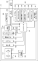
- the housing 14 has substantially the same structure as the housing of a general digital camera, and the photographing unit 20 shown in FIG. 3 and the control unit including the controller 30 and the image processing unit 32 are housed therein. ing.
- the photographing unit 20 is a device for photographing an image, and as shown in FIG. 3, the lens unit 110, the lens driving unit 120, the aperture unit 130, the shutter 140, the photographing sensor 150, and the A / D (Analog / Digital) converter. Has 160.
- the lens unit 110 includes a zoom lens 112 and a focus lens 114, and in the first embodiment, the zoom lens 112 is equipped with an anamorphic lens. Therefore, in the first embodiment, it is possible to shoot an image with a wide angle of view in the horizontal direction (for example, an angle of view with an aspect ratio of 2.35: 1).
- the lens is not limited to an anamorphic lens, and a photographic lens such as a wide-angle lens, an ultra-wide-angle lens, or a 360-degree lens may be used.
- the lens unit 110 may be configured to be interchangeable with another lens unit.
- the photographing unit 20 may include a plurality of lens units 110 having different angles of view from each other.
- the angle of view when the photographing unit 20 captures an image is determined according to the specifications of the lens unit 110 and the photographing sensor 150, and the image captured at that angle of view is the "reference image" of the present invention. Equivalent to.
- the aspect ratio of the reference image is a value corresponding to the above angle of view, and is, for example, 2.35: 1 when an anamorphic lens is used.
- the lens drive unit 120 includes a drive motor (not shown) and a drive mechanism (not shown), and moves the lens of the lens unit 110 along the optical axis.
- the aperture 130 adjusts the size of the opening according to the user's setting or automatically, and adjusts the amount of light passing through the opening.
- the shutter 140 blocks the transmitted light to the photographing sensor 150.
- the photographing sensor 150 is composed of, for example, a CCD (Charged Coupled Device) or a CMOS (Complementary Metal Oxide Semiconductor Image Sensor), and receives light from a subject via a lens unit 110 to form an image and obtains image data. Generate. Specifically, the photographing sensor 150 converts an optical signal received through a color filter into an electric signal by a light receiving element, amplifies the electric signal by an AGC (Auto Gain Controller), and analog image data from the amplified signal. To generate.
- a CCD Charge Coupled Device
- CMOS Complementary Metal Oxide Semiconductor Image Sensor
- the A / D converter 160 converts the analog image data generated by the photographing sensor 150 into digital image data.
- This digital image data corresponds to the data of the frame image constituting the reference image which is a moving image.
- the number of pixel data (that is, the number of pixels) constituting the digital image data is not particularly limited, but in the first embodiment, the number of pixels is 10 million or more, preferably the lower limit of the number of pixels is 60 million or more. It is good to be.
- the upper limit of the number of pixels in the first embodiment is preferably 1 billion or less, more preferably 500 million or less. If the number of pixels exceeds the lower limit, the visibility of the extracted image extracted from the reference image can be guaranteed. Further, if the number of pixels is less than the upper limit, the amount of pixel information of the reference image can be further reduced, so that the processing by the control unit (specifically, the image processing unit 32) is speeded up.
- the controller 30 can control each part of the photographing apparatus main body 12 according to the user's operation or automatically, for example, control the photographing unit 20 to cause the photographing unit 20 to take (acquire) a reference image. Further, the controller 30 can control the video processing unit 32 so that the video (specifically, the extracted video described later) is recorded on the recording medium. Further, the controller 30 is a lens driving unit so as to focus the focus of the lens unit 110 on the subject in the image based on the contrast of all or a part of the image indicated by the digital image data generated by the photographing unit 20. 120 can be controlled.
- the controller 30 can control the aperture unit 130 based on the brightness of all or a part of the image indicated by the digital image data generated by the photographing unit 20, and automatically adjust the exposure amount at the time of photographing. it can. Further, the controller 30 can control the lens driving unit 120 so as to automatically perform zoom (optical zoom) according to the operation of the user or according to the distance between the subject and the photographing device 10.
- zoom optical zoom
- the image processing unit 32 Under the control of the controller 30, the image processing unit 32 performs processing such as gamma correction, white balance correction, and scratch correction on the digital image data generated by the photographing unit 20, and further conforms to a predetermined standard. Compress in compression format. Then, the image processing unit 32 acquires a reference image from the compressed digital image data sequentially generated during shooting, and executes various processes on the acquired reference image. As an example of processing for the reference image, the image processing unit 32 can extract an extracted image (so-called crop image) smaller than the angle of view of the photographing unit 20 from the reference image.
- the image processing unit 32 can change the size of the range of the extracted image (hereinafter, referred to as the extraction range) in order to zoom (electronically zoom) the image of the subject in the extracted image.
- the size of the extraction range is the number of pixels of the extracted video (strictly speaking, the number of pixels in each of the vertical and horizontal directions of the extracted video).
- the control unit including the controller 30 and the video processing unit 32 is composed of one or a plurality of microcontrollers or processors.
- the control unit is composed of, for example, a CPU (Central Processing Unit) and a control program for causing the CPU to execute various processes.
- the above processors are not limited to this, and the above processors are FPGA (Field Programmable Gate Array), DSP (Digital Signal Processor), ASIC (Application Specific Integrated Circuit), GPU (Graphics Processing Unit), MPU (Micro- It may be configured by a Processing Unit) or another IC (Integrated Circuit), or may be configured by combining these.
- the functions of the entire control unit including the controller 30 and the video processing unit 32 may be configured by one IC (Integrated Circuit) chip. .. Further, the hardware configuration of each processor described above may be realized by an electric circuit (Circuitry) in which circuit elements such as semiconductor elements are combined.
- the housing 14 further houses a built-in memory 230 built in the photographing device main body 12, a memory card 240 that can be attached to and detached from the photographing device main body 12 via the card slot 260, and a buffer 250. ..
- the built-in memory 230 and the memory card 240 are recording media on which the above-mentioned extracted video is recorded, and are composed of a flash memory, a ferroelectric memory, or the like.
- the buffer 250 functions as a work memory of the controller 30 and the video processing unit 32, and is composed of, for example, a DRAM (Dynamic Random Access Memory) or a ferroelectric memory.
- various setting contents, shooting conditions, and the like are stored in the buffer 250.
- the recording medium does not have to be provided inside the photographing apparatus main body 12, and may be an external recording medium connected to the photographing apparatus main body 12 via the Internet. Further, the recording medium may be connected to the photographing apparatus main body 12 via a cable such as a USB (Universal Serial Bus) cable or HDMI (High-Definition Multimedia Interface) (registered trademark) or in a wireless format.
- a cable such as a USB (Universal Serial Bus) cable or HDMI (High-Definition Multimedia Interface) (registered trademark) or in a wireless format.
- a display device 40 is attached to the back surface of the housing 14.
- the display device 40 is composed of an LCD (Liquid Crystal Display), an organic EL (Organic Electroluminescence Display) display, an LED (Light Emitting Diode) display, electronic paper, or the like.
- Various images including the above-mentioned extracted images are displayed on the display device 40, and an operation screen for setting shooting conditions and selecting a mode is also displayed.
- the aspect ratio of the screen of the display device 40 is different from the aspect ratio of the angle of view, for example, 4: 3 or 16: 9, and the screen of the display device 40 has a higher angle of view. In comparison, the value corresponding to the horizontal width / vertical width is small.
- the housing 14 is provided with an operation unit 50, and the user performs various operations related to shooting through the operation unit 50.
- the operation unit 50 includes a release button 310, a zoom lever 320, a front operation dial 330, a rear operation dial 340, a cross button 350, and a touch wheel arranged on the housing 14. Includes 360 and the like.
- these devices transmit various control signals to the controller 30.
- the zoom lever 320 is operated, a control signal for changing the zoom magnification is transmitted to the controller 30 according to the operation, and the controller 30 moves the lens 112 in accordance with the control signal.
- the drive unit 120 is controlled.
- the display device 40 is a touch panel display and is also used as the operation unit 50.
- a control signal corresponding to the touch position is transmitted to the controller 30.
- an extraction mode selection screen (see FIG. 6), which will be described later, is displayed on the display device 40, the user selects one of the plurality of modes, and the corresponding mode selection buttons drawn on the screen are supported. Touch one button to do.
- a control signal for setting the selected mode is transmitted to the controller 30.
- the user can instruct the control unit to perform zoom processing or shutter processing (shooting processing) by touching the screen of the display device 40.
- the screen of the display device 40 is divided into three areas during shooting, and as shown in FIG. 4, the extracted image P1 is in the first area and the support image P2 is in the second area.
- Information IFs such as setting contents are displayed at the same time in the area 3.
- each of the extracted video P1, the support video P2, and the information IFs such as the setting contents will be described in detail.
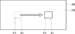
- the extracted image P1 is an image set to be smaller than the angle of view A0 at the angle of view A0 of the reference image P0, and is extracted (cut out) from the reference image P0.
- the reference video P0 is a high-quality video composed of 10 million or more (preferably 60 million or more) pixels
- the extracted video P1 extracted from the pixels is also a sufficiently high-quality video.
- the outer edge of the extracted image P1 has a rectangular shape, but the outer edge shape of the extracted image P1 is not particularly limited, and is square, parallelogram, trapezoidal, rhombic, circular or elliptical, triangular, or It may be a polygon of pentagon or more, or an indefinite shape.
- the extracted video P1 is extracted from the reference video P0 at any time by the video processing unit 32 during shooting, and is displayed in the first area on the screen of the display device 40 by the video processing unit 32. At this time, the extracted video P1 is displayed in a state in which the display size can be changed so as to fit in the first region while maintaining the aspect ratio constant.
- the extracted image P1 is displayed with the size of the angle of view A0 in the lateral direction increased when the anamorphic lens is used. This is because the image size is once compressed in the lateral direction of the angle of view A0 at the time of imaging by the photographing sensor 150, and the display size is returned to the original size when the extracted image P1 is displayed.
- the extracted video P1 is displayed in the lowermost region on the screen of the display device 40.
- the present invention is not limited to this, and for example, the extracted video P1 may be displayed in the uppermost region or the central region on the screen of the display device 40.
- the range of the extracted image P1 at the angle of view A0 that is, the extraction range A1 can be moved over time within the angle of view A0.
- “moving with time” means moving the extraction range A1 relative to the angle of view A0 so that the position of the extraction range A1 gradually changes, and the movement stops in the middle. It may include the case of (interruption).
- the movement of the extraction range A1 over time is realized by the video processing unit 32. Specifically, when the user selects one mode through the extraction mode selection screen shown in FIG. 6, the video processing unit 32 sets the extraction range A1 at an angle of view A0 along the movement path corresponding to the selected mode. Move within.
- One mode is a mode in which the extraction range A1 is moved so as to track the subject to be tracked (hereinafter, referred to as a tracking mode).
- the other mode is a mode in which the extraction range A1 is moved in a certain direction (hereinafter, referred to as a panning mode).
- the video processing unit 32 moves the extraction range A1 so as to track the subject to be tracked.
- the user specifies the image of the subject in the extracted image P1 by touching it on the screen.
- the video processing unit 32 sets a subject designated by the user as a tracking target. After that, the video processing unit 32 moves the extraction range A1 so that the subject to be tracked fits within the extraction range A1 as shown in FIG.
- the extracted image P1 showing the subject to be tracked can be constantly displayed on the display device 40. Further, the user does not have to move the photographing device 10 by himself / herself to track the subject, and therefore there is no manual change of the angle of view, and the image distortion (image blur, etc.) caused by the manual change of the angle of view is avoided. You can also do it. Such an effect is particularly effective when shooting at an angle of view when an anamorphic lens is used.
- the algorithm for searching the subject to be tracked within the angle of view A0 is not particularly limited.
- an image of a subject set as a tracking target is stored in the buffer 250 as a template image, and a known template matching technique is applied to compare the above template image with the reference image P0. Then, as a result of the comparison, the image of the portion matching the template image may be specified as the image of the subject to be tracked.
- the video processing unit 32 slides the extraction range A1 in a certain direction (for example, the lateral direction of the angle of view A0), that is, pans.
- a certain direction for example, the lateral direction of the angle of view A0
- the user sets the start position, the moving direction, the moving speed, and the like of the extraction range A1 on a setting screen (not shown).
- the video processing unit 32 automatically pans the extraction range A1 from the set start position in the set direction at the set speed.
- the panning mode when the panning mode is selected, it is possible to display on the display device 40 an image in which the shooting angle is continuously changed in a certain direction, so to speak, a panoramic image. Further, the user does not have to move the photographing device 10 by himself / herself to change the angle, and therefore there is no manual change of the angle of view, and the image distortion (image blur, etc.) caused by the manual change of the angle of view can be avoided. You can also. Such an effect is particularly effective when shooting at an angle of view when an anamorphic lens is used.
- the initially set contents are usually adopted, but the user is displayed on a setting screen (not shown).
- the aspect ratio of the extraction range A1 is the aspect ratio of the extracted video P1, and strictly speaking, it is the ratio of the number of pixels in each of the aspect ratios.
- the area ratio of the extraction range A1 is the ratio of the area of the extraction range A1 to the angle of view A0.
- the moving speed of the extraction range A1 is the number of pixels that the moving extraction range A1 passes through in a unit time when the angle of view A0 is divided in pixel units.
- an instruction by the user is received through the operation unit 50 while the extraction range A1 is moving, and the size, the moving speed, the moving direction, the moving position, and the like of the extraction range A1 are changed based on the instruction.
- the size may be changed by operating the front operation dial 330, and the moving speed may be changed by operating the rear operation dial 340.
- the moving direction may be changed by operating the cross button 350, and the moving position may be changed by the touch panel of the display device 40.
- the user can intuitively change various setting contents related to the extraction range A1 in real time according to the moving situation of the extraction range A1.
- the device operated when changing the setting content of the extraction range A1 is not limited to the above-mentioned correspondence, and for example, the size of the extraction range A1 may be changed based on the operation of the touch wheel 360. ..
- the support image P2 is an image based on the positional relationship between the angle of view A0 and the extraction range A1 during shooting, and is displayed for the user to grasp the position of the extraction range A1 within the angle of view A0 during shooting.
- the support video P2 is displayed on the display device 40 by the video processing unit 32. Specifically, the image processing unit 32 recognizes the position and size of the extraction range A1 during shooting, generates the support image P2 based on the information, and displays it on the display device 40.
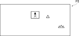
- the support image P2 is an image including the extracted image P1 as shown in FIG. 9, and in the first embodiment, the reference image P0 (strictly speaking, the reference image P0 whose display size is reduced while maintaining the aspect ratio). ) Is composed of the whole.
- the support video P2 is a video in which the position of the extracted video P1 in the support video P2 is specified. Specifically, as shown in FIG. 9, the extracted video P1 is surrounded by a frame. There is.
- the mode for specifying the position of the extracted video P1 in the support video P2 may be a mode other than the mode surrounded by a frame. For example, in the support video P2, only the display color of the extracted video P1 may be changed to the highlight color, or an instruction mark such as a cursor may be displayed in the vicinity of the extracted video P1 in the support video P2. Further, in the support video P2, the display color of the region other than the extracted video P1 may be translucent or gray to emphasize the extracted video P1.
- the position of the extraction image P1 in the support image P2 also changes in conjunction with it. If the size, aspect ratio, and position of the extraction range A1 are changed during movement, the size, aspect ratio, and position of the extracted image P1 in the support image P2 also change according to the changed settings. To do.
- the support video P2 described above is generated at any time by the video processing unit 32 based on the positional relationship between the angle of view A0 and the extraction range A1 during shooting, and is generated by the video processing unit 32 on the screen of the display device 40. It is displayed in the area of. At this time, the support image P2 is displayed in a state in which the display size can be changed so as to fit in the second area while maintaining the aspect ratio constant.
- the support image P2 has the same aspect ratio as the reference image P0 (that is, the angle of view A0).
- the reference image P0 is extended in the horizontal direction of the angle of view A0 to form a horizontally long image with an aspect ratio of 2.35: 1, and the reference image P0 is displayed as the support image P2. Displayed on the device 40.
- the aspect ratio of the display screen on the display device 40 is often different from the aspect ratio of the support image P2 (for example, 4: 3 or 16: 9).
- the support image P2 is displayed on the display device 40, a space (margin) is often generated at a position adjacent to the support image P2 in the vertical direction of the display screen.
- the extracted video P1 and the support video P2 can be simultaneously fitted on the display device 40 and displayed well.
- the support image P2 is displayed at a position directly above the extracted image P1, but the present invention is not limited to this, and the support image P2 is displayed below the extracted image P1. It may be displayed.
- the information IF such as the setting contents is information about at least one of the reference video P0 and the extracted video P1, and in the first embodiment, it is character information about each of the reference video P0 and the extracted video P1.
- the information IF such as the setting contents is displayed on the display device 40 in cooperation with the controller 30 and the video processing unit 32. Specifically, the controller 30 reads the setting contents and shooting conditions from the buffer 250, and the video processing unit 32 displays the information IF such as the setting contents on the display device 40 based on the information read by the controller 30. indicate.
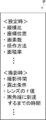
- the information IFs such as the setting contents are the setting contents (contents belonging to the category described as "at the time of setting” in FIG. 10) for each of the reference image P0 and the extracted image P1 and during shooting. (Information belonging to the category described as "at the time of shooting” in FIG. 10).
- the information displayed as the information IF such as the setting contents is not particularly limited, but as an example, the aspect ratio and the number of pixels of the extracted image P1, the position and area ratio of the extraction range A1, and the moving distance of the extraction range A1 during movement are used.
- Conditions for example, exposure conditions, lens f-number, ISO sensitivity, white balance, etc.), number of pixels in the extraction area (4K, Full HD [High Definition], etc.), frame rate at the time of moving image shooting, etc. Be done.
- the position of the extraction range A1 is a representative position of the extraction range A1 (for example, the center position or the position of four vertices), and the reference position set at the angle of view A0 (for example, the upper left vertex position of the angle of view A0). Is expressed as the coordinates when the origin is.
- the moving distance of the extraction range A1 during movement is a relative value (ratio) when the total moving distance of the extraction range A1 from the start of movement is obtained in pixel units and, for example, the length of the angle of view A0 in the moving direction is used as a reference. ).
- the estimated time until the moving extraction range A1 reaches the end of the angle of view A0 is the time required for the extraction range A1 to move to the end of the angle of view A0, from the end of the extraction range A1 to the end of the angle of view A0. It is obtained from the distance of and the moving speed of the extraction range A1.
- the setting operation method of the extraction range A1 is information indicating which device of the operation unit 50 is to be operated when "a certain content" is set with respect to the extraction range A1.
- the information IF (specifically, the position of the extraction range A1 etc.) such as the displayed setting contents changes in conjunction with it. Further, when the size and aspect ratio of the extraction range A1 are changed during the movement, the information IF such as the setting contents is updated according to the changed setting contents.
- the information IF such as the setting contents is displayed on the display device 40 together with the extracted video P1 and the support video P2 by the video processing unit 32 during shooting.
- information IFs such as setting contents are displayed at positions (for example, positions adjacent to the right) side by side with each of the extracted video P1 and the support video P2.
- an information IF such as setting contents may be displayed at an upper position or a lower position of the extracted image P1 or an upper position or a lower position of the support image P2.
- a plurality of areas on the screen of the display device 40 on which information IFs such as setting contents are displayed may be provided, information on the reference image P0 is displayed in one of the areas, and information on the extracted image P1 is displayed in another area. Information may be displayed.
- FIGS. 11 and 12 show the flow of the display flow by the photographing apparatus 10.
- the display method of the present invention is adopted.
- each step shown in FIGS. 11 and 12 corresponds to a component of the display method of the present invention.
- the display method of the present invention is adopted, and the recording step described later is executed. That is, in the above display flow, the video recording method of the present invention is adopted.
- the user activates the photographing device 10.
- the controller 30 executes the setting process (S001).
- the extraction range A1 is set within the angle of view A0 based on a preset initial value or a content instructed by the user.
- the photographing step corresponds to an acquisition step of acquiring a reference image P0 which is a moving image, and in the first embodiment, it is a step of photographing the reference image P0 at an angle of view A0 when an anamorphic lens is used.
- the video processing unit 32 executes the extraction process under the control of the controller 30 (S003).
- the video processing unit 32 extracts the video of the extraction range A1 set in the setting step, that is, the extraction video P1 from the reference video P0.
- the image processing unit 32 executes a first display step of displaying the extracted image P1 on the display device 40 and a second display step of displaying the support image P2 described above on the display device 40 in accordance with the extraction of the extracted image P1. (S004).
- the second display step is executed during the execution of the first display step.
- the extracted image P1 and the support image P2 are simultaneously displayed on the display device 40 during shooting.
- the extracted image P1 is displayed by increasing the size of the angle of view A0 in the lateral direction when the anamorphic lens is used in the first display step. Further, in the first embodiment, in the first display step, the extracted video P1 is displayed in a state in which the display size of the extracted video P1 can be changed while maintaining the aspect ratio of the extracted video P1 constant.
- the support image P2 in which the position of the extracted image P1 in the support image P2 is specified specifically, the support image P2 in which the portion of the extracted image P1 is surrounded by a frame as shown in FIG. Is displayed.
- the support video P2 is displayed in a state where the display size of the support video P2 is changed in accordance with the change in the display size of the extracted video P1.
- the third display step of displaying the information IF such as the setting contents on the display device 40 is further executed.
- information IFs such as the extracted image P1, the support image P2, and the setting contents are simultaneously displayed on the display device 40.
- the execution of the recording process is started with this as an opportunity (S005).
- the extracted video P1 is recorded by the video processing unit 32 in the built-in memory 230 or the memory card 240 as a recording medium.
- the video to be recorded is limited to the extracted video P1, and the other videos, that is, the reference video P0 and the support video P2 are discarded without being recorded. As a result, the amount of recording capacity used can be further reduced.
- the present invention is not limited to this, and one or both of the reference video P0 and the support video P2 may be recorded together with the extracted video P1.
- the moving process is executed by the image processing unit 32 (S007).
- the extraction range A1 moves along the moving path according to the mode selected by the user among the tracking mode and the panning mode described above within the angle of view A0. More specifically, when the tracking mode is selected, the extraction range A1 is moved within the angle of view A0 so that the subject to be tracked set by the user falls within the extraction range A1.
- the extraction range A1 slides (panning) based on the start position, the moving direction, and the moving speed set by the user.
- the video processing unit 32 executes the first display step, the second display step, and the third display step according to the movement of the extraction range A1 (S008).
- the first display step the extracted video P1 is displayed while the extraction range A1 is moving.
- the second display step the support image P2 is displayed so that the position of the extracted image P1 in the support image P2 changes
- the information IF such as the setting contents is displayed according to the movement of the extraction range A1. Update and display.
- step S008 as in step S005, the second display step is executed during the execution of the first display step, and the third display step is executed during the execution of both the first display step and the second display step.
- the video processing unit 32 executes the recording step so as to record the extracted video P1 while the extraction range A1 is moving by the moving step (S009).
- the above-mentioned first to third display steps and recording steps are repeated until the user gives an instruction to end shooting (S010), and the instruction to end shooting is issued.
- the operation of instructing the end of shooting by the user is not particularly limited, but for example, the operation of pressing the release button 310 again may be the operation of instructing the end of shooting.
- the user refers to the position, size, moving speed, and moving direction of the extraction range A1 (hereinafter, referred to as "position of the extraction range A1", etc. "during the execution of the moving process.
- position of the extraction range A1 the position of the extraction range A1 and the like are reset based on the user's instruction received during the execution of the moving process.
- step S007 each of the moving step, the first to third display steps, and the recording step is repeatedly executed.
- the moving process after the position of the extraction range A1 is reset, at least one of the positions of the extraction range A1 is changed based on the instruction received by the user during the execution of the moving process, and then the extraction range A1 is changed. To move.
- the information IFs such as the extraction image P1, the support image P2, and the setting contents based on the extraction range A1 whose position and the like are changed are displayed on the display device 40. Will be done. Specifically, in the first display step, the extracted video P1 after the position of the extraction range A1 is changed is displayed. In the second display step, the support image P2 in which the position of the extracted image P1 in the support image P2 is the changed position is displayed. In the third display step, the information IF such as the setting contents is updated and displayed according to the change of the position or the like of the extraction range A1.
- the video processing unit 32 appropriately executes the determination process (S013).
- the determination step is executed during the execution of the moving step, and in the determination step, between the end of the angle of view A0 and the end of the extraction range A1 (strictly speaking, the end closer to the end of the angle of view A0). Determine if the distance is less than the threshold.
- the video processing unit 32 executes the warning step (S015) and warns the user.
- the warning step S015
- the warning method in the warning process is not particularly limited, but for example, a warning message is displayed on the display device 40, or the outer edge frame of the extracted image P1 is set to a predetermined color (specifically, red or the like). It can be changed.
- the extracted image P1 smaller than the angle of view A0 can be extracted from the reference image P0, and the extraction range A1 can be moved within the angle of view A0. Further, while the extraction range A1 is moving, the user can confirm the extracted video P1 by displaying the extracted video P1 on the display device 40. At this time, it is preferable that the position of the extraction range A1 within the angle of view A0 can be grasped. Therefore, in the first embodiment, the support image P2 as an interface representing the position of the extraction range A1 within the angle of view A0 is displayed on the display device 40 together with the extraction image P1.
- the first embodiment when a change instruction by the user is received during the execution of the moving step, at least one of the position, size, moving speed, and moving direction of the extraction range A1 is changed based on the instruction. .. In such a case, the effect that the user can grasp the position of the extraction range A1 is more remarkable.
- the support video P2 includes the extracted video P1, and the position of the extracted video P1 in the support video P2 is specified (for example, the extracted video P1 is surrounded by a frame). Is displayed. As a result, the user can more easily grasp the position of the extraction range A1.
- information regarding at least one of the reference video P0 and the extracted video P1 that is, the information IF such as the setting contents is displayed on the display device 40 at the same time as the extracted video P1 and the support video P2.
- the user can confirm various information indicated by the information IF such as the setting contents, and can know more detailed information about the position of the extraction range A1 specified from the support video P2.
- the support image P2 is composed of the entire reference image P0, and in the second display step, the support image P2 is displayed on the display device 40 in a state in which the display size of the support image P2 can be changed.
- a support image different from the support image P2 according to the first embodiment for example, support images P21 and P22 shown in FIGS. 13 and 14 are displayed.
- This embodiment will be referred to as a second embodiment, and will be described below with reference to FIGS. 13 to 15.
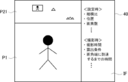
- FIGS. 13 and 14 show a screen example of the display device 40 according to the second embodiment, and correspond to FIG.
- the user selects one of the two display methods, and the support image is displayed on the display device 40 by the selected display method. That is, the second display step in the second embodiment is executed according to the display method selected by the user among the first display method and the second display method.
- the selection screen shown in FIG. 15 may be displayed on the display device 40, and the user may touch one of the display methods on the screen to select the display method.
- the support image P21 composed of the entire reference image P0 is displayed on the display device 40.
- the aspect ratio and display size of the support image P21 can be changed.
- the support image P21 in the second display step when the first display method is selected, can be displayed in a state in which the aspect ratio and display size of the support image P21 can be changed.
- the support image P21 can be displayed by crushing it in the vertical direction to reduce the display size.
- the degree of freedom in displaying the support image P21 is higher than that in the first embodiment. That is, in the second display step when the first display method is adopted, the support image P21 is displayed in a state where the aspect ratio and the display size of the support image P21 are changed in accordance with the change in the display size of the extracted image P1.
- the aspect ratio and display size of the support image P21 are adjusted to fit the space in order to display the support image P21 in the extra space. Can be changed freely.
- the support image P22 composed of a part of the reference image P0 is displayed on the display device 40.
- the support image P22 is displayed in a state in which the display size can be changed while maintaining the aspect ratio constant. That is, in the second display step when the second display method is selected, the display size of the support image P22 is changed while maintaining the aspect ratio of the support image P22 as the display size of the extracted image P1 is changed. It can be displayed in the state of.
- the user can freely set the range of the support image P22 in the reference image P0 (specifically, the range displayed as the support image P22) by operating the operation unit 50 or the like. It can be specified and the specified range can be changed freely. That is, in the second display step when the second display method is selected, the support image P22 can be displayed while moving the range of the support image P22 in the reference image P0.
- a method of designating the range of the support image P22 in the reference image P0 various methods such as button operation or touch panel operation can be mentioned, but in the second embodiment, the method using the auxiliary image Ps described later is used. Will be done.
- the image in the range specified by the user in the reference image P0 is set as the support image P22, and the aspect ratio of the support image P22 is maintained.
- the display size of the support video P22 can be changed. For example, in the reference image P0, only the range necessary for displaying as the support image P22 is specified, and then the display size of the support image P22 is appropriately adjusted. By doing so, the display space of the support image P22 in the display device 40 can be made smaller.
- the range instruction video P3 which is a video showing the range of the support video P22 in the reference video P0, is displayed together with the extracted video P1 and the support video P22. It is displayed on the device 40.
- the range instruction video P3 is composed of a reduced reference video P0 and auxiliary video Ps displayed superimposed on the reference video P0.
- the auxiliary video Ps indicates a portion corresponding to the support video P22 in the reference video P0.
- auxiliary video Ps can be moved by the user performing a touch-and-drag operation on the screen. Then, by moving the auxiliary video Ps, the range of the support video P22 in the reference video P0 can be changed.
- a step of displaying the range indication video P3 described above (hereinafter referred to as a fourth display step) is a first step. It is executed during all executions of the third display process. That is, in the second display format, the extracted image P1, the support image P22, the information IF such as the setting contents, and the range instruction image P3 are all displayed on the display device 40 at the same time.
- the second display method is selected as described above, the user can freely determine the range of the support video P22 by operating the auxiliary video Ps. Further, by confirming the support image P22 and the range instruction image P3, the position of the extraction range A1 within the angle of view A0 can be grasped.
- the display of the range instruction image P3 (that is, the execution of the fourth display step) is not always necessary, and the display of the range instruction image P3 is omitted and only the support image P22 is displayed. May be displayed.
- the extracted video P1, the support video P2, and the information IFs such as the setting contents are all displayed on the display device 40 of the same shooting device 10.
- the extracted video P1 and the support video P2 are displayed on different display devices.
- This embodiment will be referred to as a third embodiment, and will be described below with reference to FIGS. 16 to 18.
- the third embodiment relates to a display method using the photographing system S shown in FIG. That is, the display method according to the third embodiment of the present invention is realized by the photographing system S.
- the photographing system S is composed of a photographing device 10X and an external monitor.
- the basic configuration of the photographing device main body 12X according to the third embodiment is substantially the same as the basic configuration of the photographing device main body 12 according to the first embodiment.
- the photographing device main body 12X includes a first display device 410 configured by a touch panel display or the like, and is connected to a second display device 420 which is an external monitor.
- the second display device 420 is composed of a display device such as a liquid crystal monitor, a recorder with a monitor, an information processing terminal with a monitor such as a laptop personal computer, a smartphone or a tablet terminal, and the like.
- the photographing device 10X and the second display device 420 according to the third embodiment are connected by a wired system or a wireless system.
- the display device 400 for displaying images includes the first display device 410 and the second display device 420, which are separate devices from each other. Further, in the third embodiment, the video processing unit 32 of the photographing device transmits a video signal to each display device. As a result, as shown in FIG. 17, the first display device 410 displays the extracted image P1, and the second display device 420 displays the support image P2.
- the step of displaying the support image P2 on the second display device 420 (that is, that is) during the execution of the step of displaying the extracted image P1 on the first display device 410 (that is, the first display step).
- the second display step is executed.
- the second display device 420 may display an image corresponding to the display format selected by the user among the two types of support images P21 and P22 described in the second embodiment.
- the information IF such as the setting contents is displayed on the second display device 420 together with the support image P2.
- the step of displaying the information IF such as the setting contents on the second display device 420 (that is, the third display step) is provided, and the third display step includes the first display step and the second display step. Performed during both executions of the display process.
- a part of the information IF such as the setting contents for example, shooting conditions (for example, exposure conditions, lens f-number, ISO sensitivity, white balance, etc.) is displayed on the first display device 410 as shown in FIG. You may.
- the orientation detector 60 is mounted on the photographing apparatus main body 12X according to the third embodiment.
- the orientation detector 60 is composed of, for example, an acceleration sensor or the like, and detects the movement when the orientation of the photographing device 10X changes, for example, when the photographing device 10X is vertically and horizontally inverted.
- the first display device 410 when the user flips the photographing device 10X vertically and horizontally during the execution of the first display step, that is, while the extracted image P1 is displayed on the first display device 410, the first display device 410 is vertically and horizontally inverted. It is inverted and the display direction of the extracted image P1 is rotated by 90 degrees as shown in FIG.
- the controller 30 controls the video processing unit 32 according to the detection result.
- the image processing unit 32 generates the support image P2 that is vertically and horizontally inverted from the state before the orientation detector 60 detects the vertical and horizontal inversion of the photographing device 10X. Then, the video processing unit 32 transmits the video signal to the second display device 420.
- the vertically and horizontally inverted support image P2 is displayed on the second display device 420 as shown in FIG.
- the display direction of the support image P2 in conjunction with the change in the display direction of the extracted image P1 in this way, even if the first display device 410 is vertically and horizontally inverted, the extracted image P1 and the support image P2 can be combined. It becomes easier for the user to understand the correspondence.
- the information IF such as the setting contents is displayed on the second display device 420.
- the orientation detector 60 inverts the photographing device 10X vertically and horizontally. The display orientation does not change even after detection. That is, in the third display step, the information IF such as the setting contents is displayed on the second display device 420 in a state where the display orientation is maintained before and after the vertical / horizontal inversion of the first display device 410. Even when the display orientation of the extracted video P1 is reversed vertically and horizontally in this way, the information IF such as the setting content which is the character information is displayed in the normal orientation, so that the user can easily check the information IF such as the setting content. ..
- the moving image is a moving image.
- the moving image means a set of a plurality of images (frame images) continuously captured at a constant frame rate.
- the extracted video recorded on the recording medium is a moving image.
- the extracted video recorded on the recording medium may be a still image.
- the control unit including the controller 30 and the image processing unit 32 uses the still image acquired in the acquisition process (specifically, the shooting process) as the reference image P0.
- the control unit displays the still image, which is the reference image P0, on the display device 40 as the support image P2. Further, the control unit sets the extraction range A1 corresponding to the subject in the reference image P0, and displays the extraction image P1 reflected in the extraction range A1 on the display device 40. Then, when the recording process is instructed by the user and the recording process is executed, the control unit executes the recording of the still image instead of shooting the moving image, and the extracted video P1 which is the still image is recorded on the memory card 240 or the like. It may be recorded on a recording medium.
- the present invention is not limited to this, and the image acquisition process may be, for example, a process of acquiring an image for moving image editing as a reference image from the outside.
- the reference video may be acquired by downloading a moving image file of the reference video from an external data distribution device (server).
- the reference video may be acquired by reading the video to be edited from the recording medium in which the moving image file is recorded.
- a digital camera is mentioned as an example of the photographing device, but the present invention is not limited to this, and for example, a mobile terminal such as a mobile phone, a smartphone, or a tablet PC with an imaging optical system may be used. .. Further, the above-mentioned anamorphic lens may be a lens unit externally attached to the above-mentioned photographing optical system of the mobile terminal.
Landscapes
- Engineering & Computer Science (AREA)
- Multimedia (AREA)
- Signal Processing (AREA)
- Theoretical Computer Science (AREA)
- Physics & Mathematics (AREA)
- Computer Hardware Design (AREA)
- General Physics & Mathematics (AREA)
- Computing Systems (AREA)
- Studio Devices (AREA)
- Indication In Cameras, And Counting Of Exposures (AREA)
- Controls And Circuits For Display Device (AREA)
Priority Applications (6)
| Application Number | Priority Date | Filing Date | Title |
|---|---|---|---|
| JP2021548381A JP7270052B2 (ja) | 2019-09-27 | 2020-07-22 | 表示方法、及び、映像処理方法 |
| US17/704,416 US11665429B2 (en) | 2019-09-27 | 2022-03-25 | Display method and video recording method |
| US18/305,178 US12028616B2 (en) | 2019-09-27 | 2023-04-21 | Display method and video recording method |
| JP2023070036A JP7446504B2 (ja) | 2019-09-27 | 2023-04-21 | 表示方法、及び、映像処理方法 |
| JP2024026464A JP7690628B2 (ja) | 2019-09-27 | 2024-02-26 | 表示方法、及び、映像処理方法 |
| US18/668,879 US12395742B2 (en) | 2019-09-27 | 2024-05-20 | Display method and video recording method |
Applications Claiming Priority (2)
| Application Number | Priority Date | Filing Date | Title |
|---|---|---|---|
| JP2019-176631 | 2019-09-27 | ||
| JP2019176631 | 2019-09-27 |
Related Child Applications (1)
| Application Number | Title | Priority Date | Filing Date |
|---|---|---|---|
| US17/704,416 Continuation US11665429B2 (en) | 2019-09-27 | 2022-03-25 | Display method and video recording method |
Publications (1)
| Publication Number | Publication Date |
|---|---|
| WO2021059713A1 true WO2021059713A1 (ja) | 2021-04-01 |
Family
ID=75166560
Family Applications (1)
| Application Number | Title | Priority Date | Filing Date |
|---|---|---|---|
| PCT/JP2020/028347 Ceased WO2021059713A1 (ja) | 2019-09-27 | 2020-07-22 | 表示方法、及び、映像記録方法 |
Country Status (3)
| Country | Link |
|---|---|
| US (3) | US11665429B2 (https=) |
| JP (3) | JP7270052B2 (https=) |
| WO (1) | WO2021059713A1 (https=) |
Families Citing this family (2)
| Publication number | Priority date | Publication date | Assignee | Title |
|---|---|---|---|---|
| KR20260027320A (ko) * | 2016-10-04 | 2026-02-27 | 주식회사 비원영상기술연구소 | 영상 데이터 부호화/복호화 방법 및 장치 |
| JP7270052B2 (ja) | 2019-09-27 | 2023-05-09 | 富士フイルム株式会社 | 表示方法、及び、映像処理方法 |
Citations (3)
| Publication number | Priority date | Publication date | Assignee | Title |
|---|---|---|---|---|
| JP2007096588A (ja) * | 2005-09-28 | 2007-04-12 | Olympus Corp | 画像撮影装置および画像表示方法 |
| US20100271485A1 (en) * | 2009-04-24 | 2010-10-28 | Samsung Electronics Co., Ltd. | Image photographing apparatus and method of controlling the same |
| JP2011050038A (ja) * | 2009-07-27 | 2011-03-10 | Sanyo Electric Co Ltd | 画像再生装置及び撮像装置 |
Family Cites Families (5)
| Publication number | Priority date | Publication date | Assignee | Title |
|---|---|---|---|---|
| US7839446B2 (en) | 2005-08-30 | 2010-11-23 | Olympus Corporation | Image capturing apparatus and image display apparatus including imparting distortion to a captured image |
| JP2016027704A (ja) | 2014-07-04 | 2016-02-18 | パナソニックIpマネジメント株式会社 | 撮像装置 |
| JP2019022026A (ja) | 2017-07-14 | 2019-02-07 | キヤノン株式会社 | 撮像装置 |
| JP2019022028A (ja) | 2017-07-14 | 2019-02-07 | キヤノン株式会社 | 撮像装置、その制御方法およびプログラム |
| JP7270052B2 (ja) | 2019-09-27 | 2023-05-09 | 富士フイルム株式会社 | 表示方法、及び、映像処理方法 |
-
2020
- 2020-07-22 JP JP2021548381A patent/JP7270052B2/ja active Active
- 2020-07-22 WO PCT/JP2020/028347 patent/WO2021059713A1/ja not_active Ceased
-
2022
- 2022-03-25 US US17/704,416 patent/US11665429B2/en active Active
-
2023
- 2023-04-21 JP JP2023070036A patent/JP7446504B2/ja active Active
- 2023-04-21 US US18/305,178 patent/US12028616B2/en active Active
-
2024
- 2024-02-26 JP JP2024026464A patent/JP7690628B2/ja active Active
- 2024-05-20 US US18/668,879 patent/US12395742B2/en active Active
Patent Citations (3)
| Publication number | Priority date | Publication date | Assignee | Title |
|---|---|---|---|---|
| JP2007096588A (ja) * | 2005-09-28 | 2007-04-12 | Olympus Corp | 画像撮影装置および画像表示方法 |
| US20100271485A1 (en) * | 2009-04-24 | 2010-10-28 | Samsung Electronics Co., Ltd. | Image photographing apparatus and method of controlling the same |
| JP2011050038A (ja) * | 2009-07-27 | 2011-03-10 | Sanyo Electric Co Ltd | 画像再生装置及び撮像装置 |
Also Published As
| Publication number | Publication date |
|---|---|
| US12395742B2 (en) | 2025-08-19 |
| JP7446504B2 (ja) | 2024-03-08 |
| US12028616B2 (en) | 2024-07-02 |
| US11665429B2 (en) | 2023-05-30 |
| US20230254580A1 (en) | 2023-08-10 |
| US20240305891A1 (en) | 2024-09-12 |
| US20220217280A1 (en) | 2022-07-07 |
| JP2023090782A (ja) | 2023-06-29 |
| JPWO2021059713A1 (https=) | 2021-04-01 |
| JP7270052B2 (ja) | 2023-05-09 |
| JP2024052840A (ja) | 2024-04-12 |
| JP7690628B2 (ja) | 2025-06-10 |
Similar Documents
| Publication | Publication Date | Title |
|---|---|---|
| JP5331128B2 (ja) | 撮像装置 | |
| JP7690628B2 (ja) | 表示方法、及び、映像処理方法 | |
| CN102111542B (zh) | 图像处理设备、成像设备和图像处理方法 | |
| JP6942940B2 (ja) | 画像処理装置、画像処理方法及びプログラム | |
| CN106464793B (zh) | 摄像装置和摄像辅助方法 | |
| JP7000050B2 (ja) | 撮像制御装置及びその制御方法 | |
| EP3316568B1 (en) | Digital photographing device and operation method therefor | |
| JP2012065173A5 (ja) | 撮影機器、画像表示方法及びプログラム | |
| JP2010199971A (ja) | 撮像装置、撮像方法、及びプログラム | |
| JP2007124088A (ja) | 画像撮影装置 | |
| JP2020053774A (ja) | 撮像装置および画像記録方法 | |
| US20160353021A1 (en) | Control apparatus, display control method and non-transitory computer readable medium | |
| JP2016127377A (ja) | 画像処理装置及び画像処理方法、画像再生装置及び画像再生方法、並びにプログラム | |
| JP7385667B2 (ja) | 撮影装置、及び撮影方法 | |
| US8194147B2 (en) | Image presentation angle adjustment method and camera device using the same | |
| JP2024019216A (ja) | 表示方法 | |
| JP5092961B2 (ja) | 撮像装置、撮像方法及びプログラム | |
| US9261771B2 (en) | Digital photographing apparatus for displaying panoramic images and methods of controlling the same | |
| WO2013187282A1 (ja) | 撮像画像表示装置、撮像画像表示方法、記録媒体 | |
| KR20220099827A (ko) | 전자 장치 및 그 제어 방법 | |
| JP6836306B2 (ja) | 撮像制御装置、その制御方法、プログラム及び記録媒体 | |
| WO2021014598A1 (ja) | 撮像装置、撮像システム、画像処理装置、撮像方法、画像処理方法およびプログラム | |
| JP4552131B2 (ja) | デジタルカメラ、デジタルカメラの制御方法及びプログラム | |
| JP2014003715A (ja) | 撮像装置、撮像方法、及びプログラム | |
| JP2008048152A (ja) | 動画処理装置、動画撮影装置および動画撮影プログラム |
Legal Events
| Date | Code | Title | Description |
|---|---|---|---|
| 121 | Ep: the epo has been informed by wipo that ep was designated in this application |
Ref document number: 20869318 Country of ref document: EP Kind code of ref document: A1 |
|
| ENP | Entry into the national phase |
Ref document number: 2021548381 Country of ref document: JP Kind code of ref document: A |
|
| NENP | Non-entry into the national phase |
Ref country code: DE |
|
| 122 | Ep: pct application non-entry in european phase |
Ref document number: 20869318 Country of ref document: EP Kind code of ref document: A1 |