WO2021059544A1 - 状態量算出装置、制御装置および車両 - Google Patents
状態量算出装置、制御装置および車両 Download PDFInfo
- Publication number
- WO2021059544A1 WO2021059544A1 PCT/JP2019/045907 JP2019045907W WO2021059544A1 WO 2021059544 A1 WO2021059544 A1 WO 2021059544A1 JP 2019045907 W JP2019045907 W JP 2019045907W WO 2021059544 A1 WO2021059544 A1 WO 2021059544A1
- Authority
- WO
- WIPO (PCT)
- Prior art keywords
- vehicle
- calculation unit
- amount
- state quantity
- state
- Prior art date
- Legal status (The legal status is an assumption and is not a legal conclusion. Google has not performed a legal analysis and makes no representation as to the accuracy of the status listed.)
- Ceased
Links
Images

Classifications
-
- B—PERFORMING OPERATIONS; TRANSPORTING
- B60—VEHICLES IN GENERAL
- B60G—VEHICLE SUSPENSION ARRANGEMENTS
- B60G17/00—Resilient suspensions having means for adjusting the spring or vibration-damper characteristics, for regulating the distance between a supporting surface and a sprung part of vehicle or for locking suspension during use to meet varying vehicular or surface conditions, e.g. due to speed or load
- B60G17/06—Characteristics of dampers, e.g. mechanical dampers
-
- B—PERFORMING OPERATIONS; TRANSPORTING
- B60—VEHICLES IN GENERAL
- B60G—VEHICLE SUSPENSION ARRANGEMENTS
- B60G17/00—Resilient suspensions having means for adjusting the spring or vibration-damper characteristics, for regulating the distance between a supporting surface and a sprung part of vehicle or for locking suspension during use to meet varying vehicular or surface conditions, e.g. due to speed or load
- B60G17/015—Resilient suspensions having means for adjusting the spring or vibration-damper characteristics, for regulating the distance between a supporting surface and a sprung part of vehicle or for locking suspension during use to meet varying vehicular or surface conditions, e.g. due to speed or load the regulating means comprising electric or electronic elements
- B60G17/016—Resilient suspensions having means for adjusting the spring or vibration-damper characteristics, for regulating the distance between a supporting surface and a sprung part of vehicle or for locking suspension during use to meet varying vehicular or surface conditions, e.g. due to speed or load the regulating means comprising electric or electronic elements characterised by their responsiveness, when the vehicle is travelling, to specific motion, a specific condition, or driver input
- B60G17/0165—Resilient suspensions having means for adjusting the spring or vibration-damper characteristics, for regulating the distance between a supporting surface and a sprung part of vehicle or for locking suspension during use to meet varying vehicular or surface conditions, e.g. due to speed or load the regulating means comprising electric or electronic elements characterised by their responsiveness, when the vehicle is travelling, to specific motion, a specific condition, or driver input to an external condition, e.g. rough road surface, side wind
-
- B—PERFORMING OPERATIONS; TRANSPORTING
- B60—VEHICLES IN GENERAL
- B60G—VEHICLE SUSPENSION ARRANGEMENTS
- B60G17/00—Resilient suspensions having means for adjusting the spring or vibration-damper characteristics, for regulating the distance between a supporting surface and a sprung part of vehicle or for locking suspension during use to meet varying vehicular or surface conditions, e.g. due to speed or load
- B60G17/015—Resilient suspensions having means for adjusting the spring or vibration-damper characteristics, for regulating the distance between a supporting surface and a sprung part of vehicle or for locking suspension during use to meet varying vehicular or surface conditions, e.g. due to speed or load the regulating means comprising electric or electronic elements
- B60G17/018—Resilient suspensions having means for adjusting the spring or vibration-damper characteristics, for regulating the distance between a supporting surface and a sprung part of vehicle or for locking suspension during use to meet varying vehicular or surface conditions, e.g. due to speed or load the regulating means comprising electric or electronic elements characterised by the use of a specific signal treatment or control method
- B60G17/0182—Resilient suspensions having means for adjusting the spring or vibration-damper characteristics, for regulating the distance between a supporting surface and a sprung part of vehicle or for locking suspension during use to meet varying vehicular or surface conditions, e.g. due to speed or load the regulating means comprising electric or electronic elements characterised by the use of a specific signal treatment or control method involving parameter estimation, e.g. observer, Kalman filter
-
- B—PERFORMING OPERATIONS; TRANSPORTING
- B60—VEHICLES IN GENERAL
- B60W—CONJOINT CONTROL OF VEHICLE SUB-UNITS OF DIFFERENT TYPE OR DIFFERENT FUNCTION; CONTROL SYSTEMS SPECIALLY ADAPTED FOR HYBRID VEHICLES; ROAD VEHICLE DRIVE CONTROL SYSTEMS FOR PURPOSES NOT RELATED TO THE CONTROL OF A PARTICULAR SUB-UNIT
- B60W10/00—Conjoint control of vehicle sub-units of different type or different function
- B60W10/04—Conjoint control of vehicle sub-units of different type or different function including control of propulsion units
- B60W10/06—Conjoint control of vehicle sub-units of different type or different function including control of propulsion units including control of combustion engines
-
- B—PERFORMING OPERATIONS; TRANSPORTING
- B60—VEHICLES IN GENERAL
- B60W—CONJOINT CONTROL OF VEHICLE SUB-UNITS OF DIFFERENT TYPE OR DIFFERENT FUNCTION; CONTROL SYSTEMS SPECIALLY ADAPTED FOR HYBRID VEHICLES; ROAD VEHICLE DRIVE CONTROL SYSTEMS FOR PURPOSES NOT RELATED TO THE CONTROL OF A PARTICULAR SUB-UNIT
- B60W10/00—Conjoint control of vehicle sub-units of different type or different function
- B60W10/20—Conjoint control of vehicle sub-units of different type or different function including control of steering systems
-
- B—PERFORMING OPERATIONS; TRANSPORTING
- B60—VEHICLES IN GENERAL
- B60W—CONJOINT CONTROL OF VEHICLE SUB-UNITS OF DIFFERENT TYPE OR DIFFERENT FUNCTION; CONTROL SYSTEMS SPECIALLY ADAPTED FOR HYBRID VEHICLES; ROAD VEHICLE DRIVE CONTROL SYSTEMS FOR PURPOSES NOT RELATED TO THE CONTROL OF A PARTICULAR SUB-UNIT
- B60W10/00—Conjoint control of vehicle sub-units of different type or different function
- B60W10/22—Conjoint control of vehicle sub-units of different type or different function including control of suspension systems
-
- B—PERFORMING OPERATIONS; TRANSPORTING
- B60—VEHICLES IN GENERAL
- B60W—CONJOINT CONTROL OF VEHICLE SUB-UNITS OF DIFFERENT TYPE OR DIFFERENT FUNCTION; CONTROL SYSTEMS SPECIALLY ADAPTED FOR HYBRID VEHICLES; ROAD VEHICLE DRIVE CONTROL SYSTEMS FOR PURPOSES NOT RELATED TO THE CONTROL OF A PARTICULAR SUB-UNIT
- B60W30/00—Purposes of road vehicle drive control systems not related to the control of a particular sub-unit, e.g. of systems using conjoint control of vehicle sub-units
- B60W30/02—Control of vehicle driving stability
-
- B—PERFORMING OPERATIONS; TRANSPORTING
- B60—VEHICLES IN GENERAL
- B60W—CONJOINT CONTROL OF VEHICLE SUB-UNITS OF DIFFERENT TYPE OR DIFFERENT FUNCTION; CONTROL SYSTEMS SPECIALLY ADAPTED FOR HYBRID VEHICLES; ROAD VEHICLE DRIVE CONTROL SYSTEMS FOR PURPOSES NOT RELATED TO THE CONTROL OF A PARTICULAR SUB-UNIT
- B60W40/00—Estimation or calculation of non-directly measurable driving parameters for road vehicle drive control systems not related to the control of a particular sub unit, e.g. by using mathematical models
- B60W40/02—Estimation or calculation of non-directly measurable driving parameters for road vehicle drive control systems not related to the control of a particular sub unit, e.g. by using mathematical models related to ambient conditions
- B60W40/06—Road conditions
-
- B—PERFORMING OPERATIONS; TRANSPORTING
- B60—VEHICLES IN GENERAL
- B60W—CONJOINT CONTROL OF VEHICLE SUB-UNITS OF DIFFERENT TYPE OR DIFFERENT FUNCTION; CONTROL SYSTEMS SPECIALLY ADAPTED FOR HYBRID VEHICLES; ROAD VEHICLE DRIVE CONTROL SYSTEMS FOR PURPOSES NOT RELATED TO THE CONTROL OF A PARTICULAR SUB-UNIT
- B60W40/00—Estimation or calculation of non-directly measurable driving parameters for road vehicle drive control systems not related to the control of a particular sub unit, e.g. by using mathematical models
- B60W40/12—Estimation or calculation of non-directly measurable driving parameters for road vehicle drive control systems not related to the control of a particular sub unit, e.g. by using mathematical models related to parameters of the vehicle itself, e.g. tyre models
- B60W40/13—Load or weight
-
- B—PERFORMING OPERATIONS; TRANSPORTING
- B60—VEHICLES IN GENERAL
- B60W—CONJOINT CONTROL OF VEHICLE SUB-UNITS OF DIFFERENT TYPE OR DIFFERENT FUNCTION; CONTROL SYSTEMS SPECIALLY ADAPTED FOR HYBRID VEHICLES; ROAD VEHICLE DRIVE CONTROL SYSTEMS FOR PURPOSES NOT RELATED TO THE CONTROL OF A PARTICULAR SUB-UNIT
- B60W50/00—Details of control systems for road vehicle drive control not related to the control of a particular sub-unit, e.g. process diagnostic or vehicle driver interfaces
-
- B—PERFORMING OPERATIONS; TRANSPORTING
- B62—LAND VEHICLES FOR TRAVELLING OTHERWISE THAN ON RAILS
- B62D—MOTOR VEHICLES; TRAILERS
- B62D6/00—Arrangements for automatically controlling steering depending on driving conditions sensed and responded to, e.g. control circuits
-
- B—PERFORMING OPERATIONS; TRANSPORTING
- B60—VEHICLES IN GENERAL
- B60G—VEHICLE SUSPENSION ARRANGEMENTS
- B60G2400/00—Indexing codes relating to detected, measured or calculated conditions or factors
- B60G2400/05—Attitude
- B60G2400/052—Angular rate
- B60G2400/0523—Yaw rate
-
- B—PERFORMING OPERATIONS; TRANSPORTING
- B60—VEHICLES IN GENERAL
- B60G—VEHICLE SUSPENSION ARRANGEMENTS
- B60G2400/00—Indexing codes relating to detected, measured or calculated conditions or factors
- B60G2400/10—Acceleration; Deceleration
-
- B—PERFORMING OPERATIONS; TRANSPORTING
- B60—VEHICLES IN GENERAL
- B60G—VEHICLE SUSPENSION ARRANGEMENTS
- B60G2400/00—Indexing codes relating to detected, measured or calculated conditions or factors
- B60G2400/10—Acceleration; Deceleration
- B60G2400/102—Acceleration; Deceleration vertical
-
- B—PERFORMING OPERATIONS; TRANSPORTING
- B60—VEHICLES IN GENERAL
- B60G—VEHICLE SUSPENSION ARRANGEMENTS
- B60G2400/00—Indexing codes relating to detected, measured or calculated conditions or factors
- B60G2400/10—Acceleration; Deceleration
- B60G2400/106—Acceleration; Deceleration longitudinal with regard to vehicle, e.g. braking
-
- B—PERFORMING OPERATIONS; TRANSPORTING
- B60—VEHICLES IN GENERAL
- B60G—VEHICLE SUSPENSION ARRANGEMENTS
- B60G2400/00—Indexing codes relating to detected, measured or calculated conditions or factors
- B60G2400/20—Speed
- B60G2400/208—Speed of wheel rotation
-
- B—PERFORMING OPERATIONS; TRANSPORTING
- B60—VEHICLES IN GENERAL
- B60G—VEHICLE SUSPENSION ARRANGEMENTS
- B60G2400/00—Indexing codes relating to detected, measured or calculated conditions or factors
- B60G2400/25—Stroke; Height; Displacement
- B60G2400/252—Stroke; Height; Displacement vertical
-
- B—PERFORMING OPERATIONS; TRANSPORTING
- B60—VEHICLES IN GENERAL
- B60G—VEHICLE SUSPENSION ARRANGEMENTS
- B60G2400/00—Indexing codes relating to detected, measured or calculated conditions or factors
- B60G2400/30—Propulsion unit conditions
- B60G2400/32—Torque on propulsion shaft
-
- B—PERFORMING OPERATIONS; TRANSPORTING
- B60—VEHICLES IN GENERAL
- B60G—VEHICLE SUSPENSION ARRANGEMENTS
- B60G2400/00—Indexing codes relating to detected, measured or calculated conditions or factors
- B60G2400/30—Propulsion unit conditions
- B60G2400/38—Speed of engine rotation
-
- B—PERFORMING OPERATIONS; TRANSPORTING
- B60—VEHICLES IN GENERAL
- B60G—VEHICLE SUSPENSION ARRANGEMENTS
- B60G2400/00—Indexing codes relating to detected, measured or calculated conditions or factors
- B60G2400/30—Propulsion unit conditions
- B60G2400/39—Brake pedal position
-
- B—PERFORMING OPERATIONS; TRANSPORTING
- B60—VEHICLES IN GENERAL
- B60G—VEHICLE SUSPENSION ARRANGEMENTS
- B60G2400/00—Indexing codes relating to detected, measured or calculated conditions or factors
- B60G2400/60—Load
-
- B—PERFORMING OPERATIONS; TRANSPORTING
- B60—VEHICLES IN GENERAL
- B60G—VEHICLE SUSPENSION ARRANGEMENTS
- B60G2400/00—Indexing codes relating to detected, measured or calculated conditions or factors
- B60G2400/80—Exterior conditions
- B60G2400/82—Ground surface
- B60G2400/821—Uneven, rough road sensing affecting vehicle body vibration
-
- B—PERFORMING OPERATIONS; TRANSPORTING
- B60—VEHICLES IN GENERAL
- B60G—VEHICLE SUSPENSION ARRANGEMENTS
- B60G2500/00—Indexing codes relating to the regulated action or device
- B60G2500/10—Damping action or damper
-
- B—PERFORMING OPERATIONS; TRANSPORTING
- B60—VEHICLES IN GENERAL
- B60W—CONJOINT CONTROL OF VEHICLE SUB-UNITS OF DIFFERENT TYPE OR DIFFERENT FUNCTION; CONTROL SYSTEMS SPECIALLY ADAPTED FOR HYBRID VEHICLES; ROAD VEHICLE DRIVE CONTROL SYSTEMS FOR PURPOSES NOT RELATED TO THE CONTROL OF A PARTICULAR SUB-UNIT
- B60W40/00—Estimation or calculation of non-directly measurable driving parameters for road vehicle drive control systems not related to the control of a particular sub unit, e.g. by using mathematical models
- B60W40/12—Estimation or calculation of non-directly measurable driving parameters for road vehicle drive control systems not related to the control of a particular sub unit, e.g. by using mathematical models related to parameters of the vehicle itself, e.g. tyre models
- B60W40/13—Load or weight
- B60W2040/1307—Load distribution on each wheel suspension
-
- B—PERFORMING OPERATIONS; TRANSPORTING
- B60—VEHICLES IN GENERAL
- B60W—CONJOINT CONTROL OF VEHICLE SUB-UNITS OF DIFFERENT TYPE OR DIFFERENT FUNCTION; CONTROL SYSTEMS SPECIALLY ADAPTED FOR HYBRID VEHICLES; ROAD VEHICLE DRIVE CONTROL SYSTEMS FOR PURPOSES NOT RELATED TO THE CONTROL OF A PARTICULAR SUB-UNIT
- B60W50/00—Details of control systems for road vehicle drive control not related to the control of a particular sub-unit, e.g. process diagnostic or vehicle driver interfaces
- B60W2050/0001—Details of the control system
- B60W2050/0043—Signal treatments, identification of variables or parameters, parameter estimation or state estimation
- B60W2050/0052—Filtering, filters
-
- B—PERFORMING OPERATIONS; TRANSPORTING
- B60—VEHICLES IN GENERAL
- B60W—CONJOINT CONTROL OF VEHICLE SUB-UNITS OF DIFFERENT TYPE OR DIFFERENT FUNCTION; CONTROL SYSTEMS SPECIALLY ADAPTED FOR HYBRID VEHICLES; ROAD VEHICLE DRIVE CONTROL SYSTEMS FOR PURPOSES NOT RELATED TO THE CONTROL OF A PARTICULAR SUB-UNIT
- B60W2520/00—Input parameters relating to overall vehicle dynamics
- B60W2520/28—Wheel speed
-
- B—PERFORMING OPERATIONS; TRANSPORTING
- B60—VEHICLES IN GENERAL
- B60W—CONJOINT CONTROL OF VEHICLE SUB-UNITS OF DIFFERENT TYPE OR DIFFERENT FUNCTION; CONTROL SYSTEMS SPECIALLY ADAPTED FOR HYBRID VEHICLES; ROAD VEHICLE DRIVE CONTROL SYSTEMS FOR PURPOSES NOT RELATED TO THE CONTROL OF A PARTICULAR SUB-UNIT
- B60W2530/00—Input parameters relating to vehicle conditions or values, not covered by groups B60W2510/00 or B60W2520/00
- B60W2530/10—Weight
-
- B—PERFORMING OPERATIONS; TRANSPORTING
- B60—VEHICLES IN GENERAL
- B60W—CONJOINT CONTROL OF VEHICLE SUB-UNITS OF DIFFERENT TYPE OR DIFFERENT FUNCTION; CONTROL SYSTEMS SPECIALLY ADAPTED FOR HYBRID VEHICLES; ROAD VEHICLE DRIVE CONTROL SYSTEMS FOR PURPOSES NOT RELATED TO THE CONTROL OF A PARTICULAR SUB-UNIT
- B60W2530/00—Input parameters relating to vehicle conditions or values, not covered by groups B60W2510/00 or B60W2520/00
- B60W2530/20—Tyre data
-
- B—PERFORMING OPERATIONS; TRANSPORTING
- B60—VEHICLES IN GENERAL
- B60W—CONJOINT CONTROL OF VEHICLE SUB-UNITS OF DIFFERENT TYPE OR DIFFERENT FUNCTION; CONTROL SYSTEMS SPECIALLY ADAPTED FOR HYBRID VEHICLES; ROAD VEHICLE DRIVE CONTROL SYSTEMS FOR PURPOSES NOT RELATED TO THE CONTROL OF A PARTICULAR SUB-UNIT
- B60W2552/00—Input parameters relating to infrastructure
- B60W2552/35—Road bumpiness, e.g. potholes
-
- B—PERFORMING OPERATIONS; TRANSPORTING
- B60—VEHICLES IN GENERAL
- B60W—CONJOINT CONTROL OF VEHICLE SUB-UNITS OF DIFFERENT TYPE OR DIFFERENT FUNCTION; CONTROL SYSTEMS SPECIALLY ADAPTED FOR HYBRID VEHICLES; ROAD VEHICLE DRIVE CONTROL SYSTEMS FOR PURPOSES NOT RELATED TO THE CONTROL OF A PARTICULAR SUB-UNIT
- B60W2710/00—Output or target parameters relating to a particular sub-units
- B60W2710/20—Steering systems
-
- B—PERFORMING OPERATIONS; TRANSPORTING
- B60—VEHICLES IN GENERAL
- B60W—CONJOINT CONTROL OF VEHICLE SUB-UNITS OF DIFFERENT TYPE OR DIFFERENT FUNCTION; CONTROL SYSTEMS SPECIALLY ADAPTED FOR HYBRID VEHICLES; ROAD VEHICLE DRIVE CONTROL SYSTEMS FOR PURPOSES NOT RELATED TO THE CONTROL OF A PARTICULAR SUB-UNIT
- B60W2710/00—Output or target parameters relating to a particular sub-units
- B60W2710/22—Suspension systems
Definitions
- the present invention relates to a state quantity calculation device, a control device, and a vehicle.
- the calculation accuracy of the suspension stroke speed may decrease depending on the design of the vehicle. For example, the closer the standing angle of the suspension is to the road surface, the smaller the amount of front-rear movement of the wheel with respect to the displacement of the suspension tends to be.
- the conventional technology leaves room for consideration from the viewpoint of calculating the amount of vehicle state such as suspension fluctuation with high accuracy regardless of the vehicle design items such as the standing angle of the suspension. There is.
- One aspect of the present invention aims to realize a technique for calculating the state quantity of a vehicle with high accuracy.
- the state quantity calculation device includes a ground contact load calculation unit that calculates a ground contact load that is a load in the vertical direction under the spring of the vehicle, and the ground contact load calculation unit.
- the tire change amount calculation unit that calculates the current tire change amount from the ground contact load and the tire spring constant gain calculated by the tire change amount calculation unit and the tire change amount calculated by the tire change amount calculation unit are input to the vehicle model.
- a state quantity calculation unit for calculating the state quantity of the vehicle is provided.
- the state quantity calculation device includes a ground contact load calculation unit that calculates a ground contact load that is a load in the vertical direction under the spring of the vehicle, and at least the vehicle.
- the input amount calculation unit that calculates the input amount using the sensor value of the G sensor provided in the vehicle and the input amount calculated by the input amount calculation unit are input to the vehicle model to calculate the state of the first vehicle.
- the state quantity calculation device includes a ground load calculation unit that calculates a ground load, which is a load in the vertical direction under the spring of the vehicle, and at least the vehicle.
- the input amount calculation unit that calculates the input amount using the sensor value of the G sensor provided in the vehicle and the input amount calculated by the input amount calculation unit are input to the vehicle model to calculate the state amount of the first vehicle.
- the observable component unit that constitutes the observable using the ground load calculated by the ground load calculation unit, and the observable configuration that the observable component constructs. It is provided with a second state amount calculation unit that calculates the state amount of the second vehicle by correcting the state amount of the first vehicle calculated by the first state amount calculation unit.
- control device in the vehicle by using the above-mentioned state amount calculation device and the state amount of the vehicle calculated by the state amount calculation device. It includes a control unit that controls the device.
- the vehicle according to one aspect of the present invention is provided with the above-mentioned control device.
- the state quantity of the vehicle can be calculated with high accuracy.
- FIG. 1 is a diagram schematically showing an example of the configuration of the vehicle 900 according to the embodiment of the present invention.
- the vehicle 900 includes a suspension device (suspension) 100, a vehicle body 200, wheels 300, tires 310, steering member 410, steering shaft 420, torque sensor 430, steering angle sensor 440, torque application unit 460, and rack. It includes a pinion mechanism 470, a rack shaft 480, an engine 500, an ECU (Electronic Control Unit, a state amount calculation device, a control device) 600, a power generation device 700, and a battery 800.
- Examples of the vehicle 900 include a gasoline vehicle, a hybrid electric vehicle (HEV vehicle), an electric vehicle (EV vehicle), and the like.
- the wheel 300 on which the tire 310 is mounted is suspended from the vehicle body 200 by the suspension device 100. Since the vehicle 900 is a four-wheeled vehicle, four suspension devices 100, four wheels 300, and four tires 310 are provided.
- the tires and wheels of the left front wheel, the right front wheel, the left rear wheel and the right rear wheel are the tire 310A and the wheel 300A, the tire 310B and the wheel 300B, the tire 310C and the wheel 300C, and the tire 310D and the wheel, respectively. Also called 300D.
- the configurations attached to the left front wheel, the right front wheel, the left rear wheel, and the right rear wheel are represented by adding the symbols “A”, “B”, “C”, and “D”, respectively. There is.
- the suspension device 100 includes a hydraulic shock absorber, an upper arm, and a lower arm. Further, as an example, the hydraulic shock absorber includes a solenoid valve which is a solenoid valve for adjusting the damping force generated by the hydraulic shock absorber. However, this does not limit this embodiment, and the hydraulic shock absorber may use a solenoid valve other than the solenoid valve as the solenoid valve for adjusting the damping force.
- the solenoid valve may be provided with a solenoid valve using an electromagnetic fluid (magnetic fluid).
- the steering member 410 operated by the driver is connected to one end of the steering shaft 420 so as to be able to transmit torque, and the other end of the steering shaft 420 is connected to the rack and pinion mechanism 470.
- connecting so that torque can be transmitted means that the other member is connected so as to rotate with the rotation of one member, for example, one member and the other member.
- the other member is directly or indirectly fixed to one member, and one member and the other member are interlocked via a joint member or the like. At least include cases where it is connected to do so.
- the rack and pinion mechanism 470 is a mechanism for converting the rotation of the steering shaft 420 around the axis into a displacement along the axial direction of the rack and pinion 480.
- the rack shaft 480 is displaced in the axial direction, the wheels 300A and the wheels 300B are steered via the tie rod and the knuckle arm.
- the torque sensor 430 detects the steering torque applied to the steering shaft 420, in other words, the steering torque applied to the steering member 410, and provides the ECU 600 with a torque sensor signal indicating the detection result. More specifically, the torque sensor 430 detects the twist of the torsion bar provided inside the steering shaft 420 and outputs the detection result as a torque sensor signal.
- a magnetostrictive torque sensor may be used as the torque sensor 430.
- the steering angle sensor 440 detects the steering angle of the steering member 410 and provides the detection result to the ECU 600.
- the torque application unit 460 applies an assist torque or a reaction force torque according to the steering control amount supplied from the ECU 600 to the steering shaft 420.
- the torque application unit 460 includes a motor that generates an assist torque or a reaction force torque according to the steering control amount, and a torque transmission mechanism that transmits the torque generated by the motor to the steering shaft 420.
- control amount in the present specification include a current value, a duty ratio, an attenuation factor, an attenuation ratio, and the like.
- a steering device in which the steering member 410 to the rack shaft 480 are always mechanically connected is given as an example, but this does not limit the present embodiment, and the steering according to the present embodiment is not limited to this.
- the device may be, for example, a steering device of a steer-by-wire system. The matters described below can also be applied to the steering device of the steer-by-wire system.
- the vehicle 900 has a driving force transmission device (not shown).
- the driving force transmission device is, for example, a device that transmits the power of the engine to the front wheels or the rear wheels, and has a gear transmission mechanism.
- the gear transmission mechanism is a differential device that gives a difference in the number of rotations of individual wheels between the front wheels or the rear wheels according to the situation, and has a differential limiting device that limits the differential according to the running situation of the vehicle 900. are doing.
- the differential device and the differential limiting device are not limited.
- the differential device may be, for example, a bevel gear type differential device, and the differential limiting device may be a torque sensitive type such as a multi-plate clutch type limited slip differential (LSD) or a helical gear type LSD, or a viscous. It may be a rotation difference sensitive type such as LSD.
- LSD multi-plate clutch type limited slip differential
- a power generation device 700 is attached to the engine 500, and the electric power generated by the power generation device 700 is stored in the battery 800.
- the vehicle 900 is provided for each wheel 300 and includes a wheel speed sensor 320 that detects the wheel speed (angular velocity ⁇ of the wheels) of each wheel 300. Further, the vehicle 900 includes a lateral G sensor 330 that detects the lateral acceleration of the vehicle 900, a front-rear G sensor 340 that detects the longitudinal acceleration of the vehicle 900, a yaw rate sensor 350 that detects the yaw rate of the vehicle 900, and an engine 500.
- the configuration may include an engine torque sensor 510 that detects the torque to be generated, an engine rotation speed sensor 520 that detects the rotation speed of the engine 500, and a brake pressure sensor 530 that detects the pressure applied to the brake liquid of the braking device. .. The detection results by these various sensors are supplied to the ECU 600.
- the vehicle 900 includes ABS (Antilock Brake System), which is a system for preventing wheel lock during braking, TCS (Traction Control System), which suppresses wheel slippage during acceleration, and the like. It is equipped with a VSA (Vehicle Stability Assist) controllable braking device, which is a vehicle behavior stabilization control system equipped with an automatic braking function for yaw moment control during turning and a brake assist function.
- ABS Antilock Brake System
- TCS Traction Control System
- VSA Vehicle Stability Assist
- VSA Vehicle Stability Assist
- ABS, TCS, and VSA compare the wheel speed determined according to the estimated vehicle body speed with the wheel speed detected by the wheel speed sensor 320, and the values of these two wheel speeds are predetermined values. If the above differences occur, it is determined that the vehicle is in a slip state. Through such processing, ABS, TCS, and VSA aim to stabilize the behavior of the vehicle 900 by performing optimum brake control and traction control according to the traveling state of the vehicle 900.
- the vehicle 900 has a RAM (Random Access Memory) (not shown).
- the RAM stores steady-state values, estimated values, and calculated values such as vehicle weight, inertial load, and vehicle specifications.
- the steady-state value is, for example, a value of a physical quantity peculiar to the vehicle 900.
- the vehicle 900 includes an ECU (not shown) for controlling the operation of each of the suspension device 100, the steering device, and the driving force transmission device.
- the vehicle 900 has a damper ECU for controlling the suspension device 100.
- Such an ECU dedicated to the device of the vehicle 900 may be provided in the device to be controlled, or may be provided in the ECU 600 for controlling the vehicle 900.
- the suspension device 100, the steering device, and the driving force transmitting device in the vehicle 900 are all configured to be electronically controllable, and the electronically controlled suspension, the electronically controlled steering device, and the electronically controlled driving force transmitting device. It can be said that.
- the ECU 600 controls the suspension device 100 by supplying a suspension control amount. More specifically, the ECU 600 controls the opening and closing of the solenoid valve by supplying a suspension control amount to the solenoid valve included in the hydraulic shock absorber included in the suspension device 100. In order to enable this control, a power line for supplying drive power from the ECU 600 to the solenoid valve is arranged.
- the ECU 600 controls various electronic devices included in the vehicle 900 in an integrated manner. More specifically, the ECU 600 controls the magnitude of the assist torque or reaction force torque applied to the steering shaft 420 by adjusting the steering control amount supplied to the torque application unit 460.
- the ECU 600 controls the driving force transmission device by supplying, for example, a control amount of the differential limit.
- the ECU 600 adjusts the crimping strength of the clutch in the multi-plate clutch type LSD according to the driving situation, thereby exerting the driving force of the engine between the front wheels, the rear wheels, or the front wheels or the front wheels. It is distributed between the left and right wheels in the rear wheels, and the individual rotation speeds of the wheels that rotate by the driving force of the engine are controlled.
- state quantity X of the vehicle 900 in this embodiment is represented by the following formula.
- the subscripts fl, fr, rl and rr represent the left front wheel, the right front wheel, the left rear wheel and the right rear wheel in the vehicle 900, respectively.
- the subscript ii represents any one or more of the above wheels in the vehicle 900.
- w is the vertical speed of the center of gravity on the spring, which is a component in the z-axis direction of the speed on the spring of the vehicle body 200.
- p, q, and r are roll rate, pitch rate, and yaw rate, respectively, and are, for example, components of the spring angular velocity of the vehicle body 200 in the x-axis rotation direction, the y-axis rotation direction, and the z-axis rotation direction.
- the x-axis indicates the front-rear direction of the vehicle body 200
- the y-axis indicates the lateral direction of the vehicle body 200
- the z-axis indicates the vertical direction of the vehicle body 200.
- w 1fl , w 1fr , w 1rl and w 1rr are unsprung vertical speeds in each wheel.
- Damst fl , Damp St fr , Damp St rl and Damp St rr are suspension stroke displacements in each wheel.
- TireSt fl , TireSt fr , TireSt rl and TireSt rr are tire stroke displacements on each wheel.
- Equation of motion related to state quantity An example of the equation of motion of each element constituting the state quantity X is represented by the following equations (1) to (7).
- the dot " ⁇ " attached above each physical quantity represents the time derivative.
- ⁇ R z is the vertical force acting on the center of gravity of the vehicle body 200
- m 2 is the spring mass of the vehicle body 200
- u is the spring velocity in the front-rear direction of the vehicle body 200
- v is the lateral force of the vehicle body 200. Represents the sprung velocity in the direction.
- I zx is the lateral (for example, y-axis) inertial product on the spring of the vehicle body 200
- I x is the moment of inertia about the x-axis passing through the center of gravity of the vehicle body 200
- I y is. moment of inertia about the y-axis passing through the center of gravity of the vehicle body 200
- I z denotes the moment of inertia, about the z axis passing through the center of gravity of the vehicle body 200.
- m 1ii represents the unsprung mass of any wheel
- R zi i represents the suspension reaction force applied under the spring of each wheel
- k 1ii represents the tire spring constant of any wheel.
- DampV ii represents the suspension stroke speed of each wheel
- w ii represents the vertical velocity of the suspension points on each wheel of the spring.
- TireV ii represents the tire stroke speed of each wheel
- w 0Ii represents the differential value of the road surface displacement at any of the wheels point. wii is represented by the following formulas (6a) to (6d). In the formulas (6a) to (6d), tr f and tr r represent the front and rear tread half length of the vehicle body 200, and l f and l r represent the distance between the front and rear axle centers of gravity of the vehicle body 200.
- R zfl, R zfr, R zrl, and R zrr represent the suspension reaction force on each wheel
- DampF fl, DampF fr, DampF rl, and DampF rr represent the damper damping force on each wheel.
- k 2f and k 2r are the spring constants of the suspension springs of the front wheels and the rear wheels
- C 2f and C 2r are for improving the stability of the vehicle model described later with respect to the front wheels and the rear wheels.
- the parameters of, and kaf , kar represent the stiffness of the stabilizers on the front and rear wheels.
- the longitudinal force ⁇ R x acting on the center of gravity of the vehicle body 200, the lateral force ⁇ R y acting on the center of gravity of the vehicle body 200, and the vertical force ⁇ R z acting on the center of gravity are the following equations (12) to (14), respectively. ).
- ⁇ F x0 represents the front-rear force of all the tires of the vehicle 900
- ⁇ F y0 represents the lateral force of all the tires of the vehicle 900.
- M xR represents a reaction force moment around the x-axis of the suspension acting on the center of gravity of the vehicle body 200
- MyR is around the y-axis of the suspension acting on the center of gravity of the vehicle body 200.
- M zR represents the reaction force moment around the z-axis of the suspension acting on the center of gravity of the vehicle body 200.
- h 1 represents the average of the z-axis direction distances from the center of gravity of the vehicle 900 to the unsprung mass of each wheel.
- M xtire represents a reaction force moment around the x-axis of the tire acting on the center of gravity of the vehicle body 200
- Mytire is around the y-axis of the tire acting on the center of gravity of the vehicle body 200
- M ztire represents the reaction force moment around the z-axis of the tire acting on the center of gravity.
- R 0 represents the tire radius.
- M x, M y and M z can be expressed by the following equation (21) to (23).
- the input value to the ECU 600 in this embodiment can be represented by, for example, the following matrices U 1 and U 2.
- the observed value to the ECU 600 can be represented by the following matrix Y.
- Equation (26) is derived from the equation (24), and the equation (27) is derived from the equation (25).
- the last term on the right-hand side in equations (26) and (27) represents an error.
- equation (24) is represented by the following equation (31).
- the equation of motion described above is represented by a linear system that is calculated linearly.
- the following equations (32), (33), and (34) are derived.
- Ac is represented as a system matrix representing the unique characteristics of the vehicle 900.
- B c is represented as an input matrix representing the effect of the input on the vehicle 900.
- C c is represented as an observation matrix for outputting the observation amount from the vehicle 900.
- the vehicle model a state amount and includes the elements of the matrix U 1, U 2 vehicle 900 As is apparent from, and has a single model that shows the behavior of the entire vehicle.
- Equation (32), (33) and (34) The Ac, Bc and Cc matrices are discretized by the following equations (32), (33) and (34) as described above. That is, Ac represents a discretized system matrix, Bc represents a discretized input matrix, and Cc represents a discretized observation matrix.
- L -1 represents an inverse Laplace operation process, s represents a Laplace operator, and I represents an identity matrix.
- ⁇ t represents the sample time.
- the vehicle model for estimating the vehicle state quantity in the present embodiment can be represented by the following equations (35) and (36).
- the vehicle model is a single model showing the behavior of the entire vehicle, including the elements of the vehicle 900.
- the subscript k represents an arbitrary step in the discrete state
- k-1 represents the step one step before k.
- the Xk hat is the state quantity of the vehicle model, that is, the estimated vehicle state quantity.
- the Xk hat is represented by the following matrix.
- the U k hat is an input value, and is represented by, for example, the U1 k hat and the U2 k hat of the following formula.
- the Yk hat is an observable, that is, an estimated vehicle observable.
- the Yk hat is represented by the following matrix.
- a state quantity according to the above-mentioned logic is calculated, and the operation of the suspension device 100 is controlled using the state quantity.
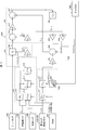
- FIG. 2 is a block diagram showing an example of the functional configuration of the control device according to the first embodiment of the present invention.
- the ECU (control device) 600 includes a ground load calculation unit 610, an input amount calculation unit 620, a first state quantity calculation unit 630, an observation quantity calculation unit 640, a second state quantity calculation unit 650, and the like.
- a damper ECU 660 is provided.
- the ECU 600 includes a yaw rate sensor 350, a wheel speed sensor 320, a steering angle sensor 440, a lateral G sensor 330, and a front / rear G sensor 340.
- RAM 601 is connected.
- the ground load calculation unit 610, the input amount calculation unit 620, the first state quantity calculation unit 630, the observation amount calculation unit 640, and the second state quantity calculation unit 650 correspond to the state quantity calculation device.
- the ground contact load calculation unit 610 calculates the ground contact load.
- the ground contact load is a vertical load under the unsprung mass of the vehicle.
- the ground contact load calculation unit 610 includes a wheel speed fluctuation calculation unit 614 that calculates the wheel speed fluctuation ⁇ Vw from the wheel speed Vw acquired by the inertial load calculation unit 611, the road surface load calculation unit 612, the ground contact load calculation unit 613, and the wheel speed sensor 320. I have.
- the inertial load calculation unit 611 calculates the inertial load.
- the inertial load is a ground contact load component generated by a change in behavior due to an inertial force acting on the vehicle 900.
- the inertial load calculation unit 611 acquires the wheel speed Vw acquired by the wheel speed sensor 320, the steering angle ⁇ s acquired by the steering angle sensor 440, the lateral acceleration ay acquired by the lateral G sensor 330, and the front-rear G sensor 340.
- the longitudinal acceleration a x, and each of the wheels of the inertia load dFz0 inertiafl the vehicle specifications such as the vehicle weight m stored in the RAM601 as an input value, calculates fr, rl, and rr.
- fr, rl, and rr When "d" is added before the physical quantity of the vehicle, it means the fluctuation or difference of the physical quantity.
- the road surface load calculation unit 612 calculates the road surface load from the wheel speed, the wheel speed fluctuation, the steady load Fz0 nom, and the inertial load.
- the road surface load is a ground contact load component due to the unevenness of the road surface.
- the road surface load calculation unit 612 stores the wheel speed fluctuation ⁇ Vw calculated by the wheel speed fluctuation calculation unit 614, the inertial load dFz0 inertiafl, fr, rl, rr of each wheel calculated by the inertial load calculation unit 611, and the RAM 601.
- the road surface load dFz0 roadfl, fr, rl, rr of each wheel is calculated by inputting the vehicle weight m, the steady load Fz0 nom, the vehicle specifications, and the like.
- the ground contact load calculation unit 613 calculates the ground contact load from the inertial load and the road surface load.
- the ground contact load calculation unit 613 includes the inertial load dFz0 inertiafl, fr, rl, rr of each wheel calculated by the inertial load calculation unit 611, and the road surface load dFz0 roadfl, fr, rl of each wheel calculated by the road surface load calculation unit 612. , Rr , and steady load Fz0 nom (not shown) are used as input values to calculate the ground contact load dFz0 fl, fr, rl, rr of each wheel.
- the input amount calculation unit 620 calculates the input amount using at least the sensor value of the G sensor provided in the vehicle. For example, the input amount calculation unit 620 calculates the input amount from the G sensor value, the vehicle weight, and the damper current value.
- the input amount calculation unit 620 includes a calculation unit 621, a map 622, and an input amount configuration unit 623.
- Calculation unit 621 for example, lateral acceleration lateral G sensor 330 acquires a y, the acceleration before and after the G sensor 340 is acquired before and after a x, as well as an input value the vehicle weight m stored in the RAM 601, the vehicle body 200 The front-rear direction force ⁇ R x acting on the center of gravity and the lateral force ⁇ R y acting on the center of gravity of the vehicle body 200 are calculated.
- Map 622 shows the correlation between suspension stroke speed and damper current and damper attenuation, and can be represented as a graph or equation.
- the map 622 uses, for example, the suspension stroke speeds of each wheel, DampV fl, fr, rl, rr , which will be described later, and the damper currents of each wheel, Damper fl, fr, rl, rr, as input values, and the map 622 of each wheel according to the input value.
- the damper attenuation amount DampF fl, fr, rl, rr is output.
- the damper currents Damper current DampCur fl, fr, rl, rr are feedback values from the damper ECU 640.
- the input amount component unit 623 uses the front-rear direction force ⁇ R x and the lateral force ⁇ R y calculated by the calculation unit 621 and the damper damping amount DampF fl, fr, rl, rr output by the map 622 as input values, and inputs the input amount. To configure.
- the input amount is, for example, represented by the matrix U 2 described above.
- the first state quantity calculation unit 630 inputs the input amount calculated by the input quantity calculation unit 620 into the vehicle model described above to calculate the first state quantity of the vehicle 900.
- the first state quantity calculation unit 630 includes a calculation unit 631, 633, a delay unit 632, an extraction unit 634, and an addition unit 635.
- the calculation unit 631 calculates the product of the input amount calculated by the input amount constituent unit 623 and the input matrix B. As a result, the influence of the input amount on the vehicle model is reflected in the first state quantity calculated later.
- the delay unit 632 sets the second state quantity X 2k hat of step k, which will be described later, as the second state quantity X 2k-1 hat of step k-1 one step before.
- the calculation unit 633 calculates the product of the second state quantity X 2k-1 hat generated by the delay unit 632 and the system matrix A. As a result, the characteristics peculiar to the vehicle model are reflected in the first state quantity calculated later.
- the extraction unit 634 calculates the suspension stroke speeds DampV fl, fr, rl, rr of each wheel from the second state quantity X 2k-1 hat generated by the delay unit 632. For example, the extraction unit 634 extracts the suspension stroke component of each wheel from the second state quantity X 2k-1 hat, appropriately differentiates the extracted component, or adjusts it with an appropriate gain to suspend the suspension of each wheel.
- the stroke speeds DampV fl, fr, rl, rr are calculated.
- the obtained calculated value is represented by a 4 ⁇ 1 matrix composed of the suspension stroke speed, and is an input value of the above-mentioned map 622.
- the addition unit 635 adds the product of the input amount calculated by the calculation unit 631 and the input matrix B, and the product of the second state quantity X 2k-1 hat calculated by the calculation unit 633 and the system matrix A. Calculate one state quantity X'2k hat.
- the observation amount calculation unit 640 calculates the observation amount from the ground contact load calculated by the ground contact load calculation unit 610 and the spring constant gain of the tire.
- the observation amount calculation unit 640 includes a tire stroke calculation unit 641 and an observation amount component unit 642.
- Tire stroke displacement TireSt ii of each wheel is expressed by the following equation (37).
- the tire stroke calculation unit 641 is based on the ground contact load dFz0 fl, fr, rl, rr of each wheel calculated by the ground contact load calculation unit 613 and the tire spring constant gain G, and the tire stroke TireSt fl, fr, rl, rr of each wheel. Is calculated.
- Tire stroke displacement is an aspect of the amount of change in the tire.
- the observation amount component unit 642 constitutes an observation amount including the change amount of the current tire.
- the observation amount component unit 642 configures the observation amount Yk by inputting the tire stroke displacement calculated by the tire stroke calculation unit 641 and the yaw rate detection value acquired by the yaw rate sensor 350 as input values.
- the tire stroke displacement is the amount of change in the tire radius, and is an aspect of the amount of change in the tire.
- the observed amount Y k is, for example, a 5 ⁇ 1 matrix and is expressed as follows.
- the subscripted sense means that it is an observable.
- r sense k is a detected value of the yaw rate sensor 350
- TireStii sense k is a tire stroke displacement calculated by the tire stroke calculation unit 641.
- the observation amount calculation unit 640 may not include the tire stroke calculation unit 641, and the observation amount configuration unit 642 may directly configure the ground contact load calculated by the ground contact load calculation unit 613 as the observation amount.
- the second state quantity calculation unit 650 uses the observation quantity Y k calculated by the observation quantity calculation unit 640 to correct the first state quantity X'2k hat of the vehicle 900 calculated by the first state quantity calculation unit 630.
- the second state quantity of the vehicle 900 is calculated by X 2k hat.
- the second state quantity calculation unit 650 includes calculation units 651 and 653, a subtraction unit 652, and an addition unit 654.
- the calculation unit 651 calculates the observed quantity from the already-existing state quantity. For example, the arithmetic unit 651 multiplies the X 2k-1 hat represented by the n ⁇ 1 matrix output by the delay unit 632 by the output matrix C represented by the p ⁇ n matrix, and predicts the prediction from the state quantity. Calculate the observable Yk hat.
- the subtraction unit 652 calculates the subtraction value of the observation amount by subtracting the estimated observation amount Yk hat calculated by the calculation unit 651 from the observation amount Yk configured by the observation amount composition unit 642. It can be said that Y k is an observable based on actual measurement, and Y k hat is an estimated observable.
- the calculation unit 653 multiplies the subtraction value of the observed amount calculated by the subtraction unit 652 by the Kalman gain K.
- the Kalman gain K is the gain of the Kalman filter.
- the addition unit 654 adds the first state quantity X'2k hat calculated by the addition unit 635 and the value obtained by multiplying the difference obtained by subtracting the estimated observation amount from the observation amount based on the actual measurement by Kalman gain K.
- the second state quantity X 2k hat which is the state quantity corrected in this way, is calculated.
- the second state quantity X 2k hat is output to the delay unit 632 described above.
- the second state quantity calculation unit 650 further uses the Kalman gain to correct the first state quantity X'2k hat. Therefore, it can be said that the second state quantity calculation unit 650 constitutes the Kalman filtering block.
- the damper ECU 660 controls the suspension device 100 by using the calculated value of the state quantity of the vehicle 900.
- the damper ECU 660 corresponds to a control unit that controls a device included in the vehicle 900.
- Damper ECU670 for example, the second state quantity X 2k-1 hat outputted from the delay unit 632, and the extraction unit 634 is the second state quantity X 2k-1 in each extracted from a hat wheel suspension stroke speed DampV fl,
- the operation of the suspension device 100 is controlled by, for example, skyhook control, using fr, rl, and rr as input values.
- the ECU 600 includes the above-mentioned ground load calculation unit 610, input amount calculation unit 620, first state amount calculation unit 630, observation amount calculation unit 640, and second state amount calculation.
- a unit 650 is provided.
- the observed amount based on the ground contact load is expressed in units of displacement, that is, length, and the state amount is calculated using the observed amount.
- the control amount of the suspension device 100 is usually represented by displacement information of an object to be controlled, that is, a physical quantity expressed in units of length.
- the control result of the state quantity based on the calculation result using the observed quantity is stable in the above control.
- the displacement information is not represented, that is, when an observable other than the unit of length is used for the above control calculation, the behavior due to the displacement of the controlled object controlled based on the calculation result may not be determined.
- the calculation result for control may diverge without converging. Therefore, when a unit other than the unit of length is used for the control calculation, the control accuracy or the like may be deteriorated by using the divergent calculation result. Further, in order to prevent this, it is necessary to take another measure such as a process of offsetting the entire system so that the calculation result always falls within a predetermined range. Therefore, in the present embodiment, it is possible to stabilize the calculation of the state quantity with a simpler configuration than in the case of calculating the state quantity based on the observed quantity of the unit that does not represent the position information.
- the observed amount is calculated from the acquired value of the general-purpose sensor, and such an observed amount is used for correcting the state amount. That is, in the present embodiment, the state quantity corrected by the observed quantity is calculated. Therefore, in the present embodiment, a better estimation result of the state quantity can be obtained as compared with the case where the state quantity is not corrected by the observed quantity. Therefore, according to the present embodiment, it is possible to calculate the state quantity of the vehicle with higher accuracy than in the case where the above-mentioned observation quantity is not used.
- the observed amount is calculated using the acquired value of the general-purpose sensor as the sensor value. Therefore, it is possible to calculate the state quantity of the vehicle with high accuracy as described above without using a special sensor.
- the observed amount includes the amount of change in the current tire. Therefore, it is suitable as a physical quantity representing the state of a traveling vehicle. Therefore, this configuration is more effective as a state quantity for controlling the traveling state of the vehicle with high accuracy.
- the amount of change in the tire is the amount of change in the tire radius, that is, the displacement of the tire stroke. It is expected that the tire stroke displacement contributes more to the calculation of the state quantity among the tire changes. Therefore, this configuration is even more effective from the viewpoint of suppressing an error in the calculation of the state quantity.
- the second state quantity calculation unit 650 constitutes a Kalman filtering block, and corrects the first state quantity of the vehicle 900 by Kalman filtering using Kalman gain.
- the first state quantity is calculated based on the more suitable observable corrected by the Kalman filter. Therefore, the above configuration calculates a more appropriately corrected state quantity based on an appropriately corrected observable, as compared with the case where the state quantity is calculated using an observable that does not include such correction. It is even more effective from the point of view.
- the ground contact load calculation unit 610 includes the above-mentioned inertial load calculation unit 611, a road surface load calculation unit 612, and a ground contact load calculation unit 613. Therefore, it is possible to accurately estimate the ground contact load from the detected value of the general-purpose sensor. Therefore, this configuration is even more effective from the viewpoint of improving the accuracy of the observed amount without using a special sensor.
- the vehicle model of this embodiment uses a single model that can express the behavior of the entire vehicle. Therefore, the influence of the entire vehicle on all wheels is reflected in the calculation of the state quantity. For example, there is a situation in which the influence exerted on an arbitrary wheel further affects the vehicle body, another wheel, or the like.
- a one-wheel model that completes the calculation of the state quantity for each wheel is used in combination for the number of wheels, the state quantity calculated in such a situation may be far from the actual behavior of the vehicle. Therefore, this configuration is more effective from the viewpoint of expanding the range of situations in which the state quantity of the vehicle can be appropriately calculated, as compared with the case of using a one-wheel model in which the calculation of the state quantity is completed for each wheel.
- the ECU 600 includes the above-mentioned state quantity calculation device and the above-mentioned damper ECU 660 as a control unit. Therefore, it is possible to appropriately control the device included in the vehicle 900 by using the state quantity calculated as described above, and as a result, the traveling state of the traveling vehicle 900 is appropriately controlled. Therefore, this configuration can further improve the running stability of the vehicle as compared with the case of controlling without using the above-mentioned state quantity.
- the device included in the vehicle 900 is, for example, a suspension device 100 as an electronically controlled steering device. According to this configuration, the suspension device of the traveling vehicle can be controlled more appropriately.
- the vehicle 900 is provided with the above-mentioned ECU 600. Therefore, the running state of the vehicle 900 is appropriately controlled. Therefore, according to this configuration, it is possible to provide a vehicle 900 having improved running stability.
- the step of calculating the ground contact load which is the load in the vertical direction under the spring of the vehicle
- the step of calculating the input amount from the G sensor value, the vehicle weight, and the damper current value, and the input amount are set.
- the input amount calculated in the calculation step is input to the vehicle model to calculate the state amount of the first vehicle, and the ground contact load calculated in the step of calculating the ground contact load and the spring constant gain of the tire.
- a method for calculating the state amount is implemented, which includes a second step of calculating the state amount of the vehicle. Therefore, as described above, the state quantity of the vehicle 900 can be calculated with high accuracy.
- the ECU 600 further includes a wheel speed correction unit.
- the wheel speed correction unit corrects the wheel speed by, for example, using the wheel speed Vw acquired by the wheel speed sensor 320 as an input value and removing the wheel speed fluctuation component due to the change in the suspension geometry from the wheel speed Vw.
- the wheel speed correction unit outputs the wheel speed Vw corrected in this way to the ground contact load calculation unit 610.
- the ground contact load calculation unit 610 calculates the ground contact load as described above using the corrected wheel speed Vw.
- the wheel speed correction unit may correct the wheel speed difference ⁇ Vw instead of the wheel speed Vw.
- the tire receives a force in the axial direction due to the expansion and contraction of the suspension, and the wheel speed fluctuates according to the force.
- the wheel speed sensor 320 detects the wheel speed that fluctuates according to the above-mentioned force, but in the above-mentioned calculation of the state quantity, the fluctuation amount of the wheel speed due to the operation of such a suspension becomes noise.
- the wheel speed correction unit removes such a noise component from the acquired value of the wheel speed sensor 320.
- the ground contact load calculation unit 610 can calculate the ground contact load using the wheel speed Vw from which the noise has been removed, and the observation amount calculation unit 640 uses the ground contact load to calculate each wheel. Tire stroke can be calculated. As described above, in the present embodiment, the component that becomes noise is removed before the state quantity is calculated.
- the ECU 600 further includes a wheel speed correction unit that corrects the wheel speed by removing a wheel speed fluctuation component due to a change in suspension geometry. This configuration is more effective from the viewpoint of calculating the state quantity with high accuracy as compared with the case where the ECU 600 does not include the wheel speed correction unit.
- the ECU 600 further includes a normative model for calculating an ideal vehicle state.
- the normative model is, for example, one or more models relating to the running state of the vehicle 900.
- the first model and the second model are in an appropriate form used in the above-mentioned calculation of the state quantity.
- these models can be represented in the form of gain in gain processing on the calculated value, or in the form of a map.
- These models are stored in the RAM 601 in the form of, for example, a gain for the first model, a map for the second model, and the like.
- the ECU 600 may further include a model input unit that receives an instruction of a normative model from the driver of the vehicle 900.
- the model input unit receives the operation of the driver who selects either the first model or the second model
- the ECU 600 selects the normative model according to the operation and gains or maps corresponding to the selected model. Is used to calculate the state quantity.
- the damper ECU 660 controls the suspension device 100 so as to reduce the difference between the ideal vehicle state and the state amount. For example, when the state amount is calculated based on the first model, the damper ECU 660 controls to improve the operation stability rather than the control amount to improve the riding comfort so as to further enhance the feeling of contact with the tire.
- the suspension device 100 is controlled by increasing the amount.
- the state amount is calculated based on the second model, the ride comfort is more important than the control amount for improving the operation stability so that the comfort of the occupant of the vehicle 900 during running is further enhanced.
- the suspension device 100 is controlled by increasing the amount of control for increasing the amount.
- the ECU 600 further includes the above-mentioned normative model, and the damper ECU 660 controls the suspension device 100 so as to reduce the difference between the ideal vehicle state and the state amount.
- This configuration is even more effective from the viewpoint of realizing a desired vehicle state by using the state quantity calculated with high accuracy as described above.
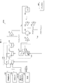
- FIG. 3 is a block diagram showing an example of the functional configuration of the control device according to the third embodiment of the present invention.
- the ECU 600a of the third embodiment is different from the ECU 600 of the above-described embodiment in that it includes 670 instead of the input amount calculation unit 620 and does not include the observation amount calculation unit 640 and the second state quantity calculation unit 650.
- the ECU 600a includes a ground contact load calculation unit 610, a tire change amount calculation unit 670, a first state amount calculation unit 630, and a damper ECU 660.
- the wheel speed sensor 320, the steering angle sensor 440, the lateral G sensor 330, the front / rear G sensor 340, and the RAM 601 are connected to the ECU 600a.
- the tire change amount calculation unit 670 calculates the amount of change in the tire of the tire change amount calculation unit 670.
- the amount of change in the tire is, for example, the tire stroke displacement, which is the amount of change in the radius of the tire.
- the tire change amount calculation unit 670 includes a tire stroke calculation unit 641, a map 622, and a calculation unit 671.
- the calculation unit 671 uses the above-mentioned matrix of the tire strokes TireStfl, fr, rl, rr of each wheel calculated by the tire stroke calculation unit 641 and the damper damping amount DampF fl, fr, rl, rr output by the map 622. Input to U 1k to obtain the matrix U k.
- arithmetic unit 631 multiplies the input matrix B by the calculation unit 671 described above to the matrix U k calculated.
- the input matrix B is a matrix representing the influence of the input on the system (equation of motion).
- the delay unit 632 sets the state quantity Xk hat to the one one step before.
- Embodiment 4 Niite, the state quantity and X 1k hat, and the state quantity X 1k-1 hat step k-1.
- the calculation unit 633 calculates the product of the state quantity X 1k-1 hat and the system matrix A.
- the extraction unit 634 extracts the suspension stroke components of each wheel from the state quantity X 1k-1 hat, adjusts them appropriately, and sets the suspension stroke speeds of each wheel to DampV fl, fr, rl, rr . calculate.
- the calculated value obtained is an input value of the map 622.
- the addition unit 635 adds the product of the matrix Uk and the input matrix B and the product of the state quantity X 1k-1 hat and the system matrix A to calculate the state quantity X 1k hat.
- the damper ECU 660 controls the suspension device 100 by using the calculated value of the state quantity of the vehicle 900.
- the damper ECU 660 acquires the state quantity X 1k-1 hat from the delay unit 632, and acquires the suspension stroke speeds DampV fl, fr, rl, rr of each wheel from the extraction unit 634. According to these acquired values, the operation of the suspension device 100 is controlled by, for example, skyhook control. Further, the damper currents of each wheel, Damper currents Damper fl, fr, rl, and rr , are output to the map 622.
- the ECU 600a includes the above-mentioned ground contact load calculation unit 610, tire change amount calculation unit 670, and first state amount calculation unit 630.
- the tire change amount is used to calculate the state amount based on the ground contact load. Therefore, as in the above-described embodiment, the state quantity is calculated based on the displacement, that is, the tire change amount which is a calculated value expressed in units of length, so that the calculation result of the state quantity is stable. Therefore, in this embodiment as well, as in the above-described embodiment, the calculation of the state quantity is stable as compared with the case where the displacement information is not represented, that is, the state quantity is calculated based on the observed quantity other than the unit of length. It is possible to make it.
- the observed amount is calculated using the acquired value of the general-purpose sensor as the sensor value. Therefore, it is possible to calculate the state quantity of the vehicle with high accuracy as described above without using a special sensor.
- the amount of change in the tire is the tire stroke displacement. Therefore, as in the above-described embodiment, this configuration is even more effective from the viewpoint of suppressing an error in the calculation of the state quantity.
- the ground contact load calculation unit 610 includes the above-mentioned inertial load calculation unit 611, a road surface load calculation unit 612, and a ground contact load calculation unit 613. Therefore, it is possible to accurately estimate the ground contact load from the detected value of the general-purpose sensor. Therefore, in this configuration, the ground contact load and the tire change amount can be calculated without using a special sensor, and the state amount can be calculated with higher accuracy.
- the vehicle model of this embodiment uses a single model that can express the behavior of the entire vehicle. Therefore, the influence of the entire vehicle on all wheels is reflected in the calculation of the state quantity. For example, there is a situation in which the influence exerted on an arbitrary wheel further affects the vehicle body, another wheel, or the like.
- a one-wheel model that completes the calculation of the state quantity for each wheel is used in combination for the number of wheels, the state quantity calculated in such a situation may be far from the actual behavior of the vehicle. Therefore, this configuration is more similar to the above-described embodiment from the viewpoint of expanding the range of situations in which the state quantity of the vehicle can be appropriately calculated, as compared with the case of using the one-wheel model in which the calculation of the state quantity is completed for each wheel. It is even more effective.
- the ECU 600a further includes a damper ECU 660. Therefore, as in the above-described embodiment, this configuration can further improve the running stability of the vehicle as compared with the case of controlling without using the above-mentioned state quantity.
- the device included in the vehicle 900 is, for example, a suspension device 100 as an electronically controlled steering device. Therefore, according to this configuration, it is possible to more appropriately control the suspension device of the traveling vehicle, as in the above-described embodiment.
- the vehicle 900 is provided with the above-mentioned ECU 600. Therefore, according to this configuration, it is possible to provide the vehicle 900 having improved running stability, as in the above-described embodiment.
- the ECU of the present embodiment is equipped with a camera capable of photographing the road surface in the traveling direction of the vehicle 900, and the road surface load calculation unit 612 calculates the road surface load based on the image captured by the camera. Similar to form.
- the camera captures the road surface of the vehicle 900 in the traveling direction.
- the road surface load calculation unit 612 acquires the data of the unevenness of the photographed road surface. Further, the road surface load calculation unit 612 is based on the current traveling state of the vehicle 900, the acquired value of the sensor, and the vehicle specifications stored in the RAM 601. Calculate loadfl, fr, rl, rr .
- the above camera may be a camera possessed by a drive recorder, as long as it can capture a road surface condition such as unevenness in the traveling direction of the vehicle 900.
- the state quantity can be predicted, and the specific location can be predicted before actually passing through the specific location (photographed location) of the road surface. It is possible to predict the amount of state when passing. Therefore, the above configuration has an effect that it is possible to prevent the occurrence of a delay in control in the running state of the vehicle based on the state quantity, as compared with the above-described embodiment.
- the ECU of the present embodiment further exerts the effect according to the configuration other than the road surface load calculation unit 612 among the effects of the above-described embodiment.
- the ECU of this embodiment has the same configuration as that of the above-described embodiment except that it further includes a steering ECU.
- the steering ECU adjusts the steering control amount supplied to the torque application unit 460 based on the state quantity X k hat (or X k-1 hat) calculated by the ECU, thereby applying the assist torque or the assist torque to the steering shaft 420. Controls the magnitude of reaction torque.
- the suspension it is possible to control the suspension so that the vehicle 900 behaves favorably according to the steering based on the above-mentioned state quantity. Further, in the present embodiment, based on the above-mentioned state quantity, the passenger feels favorable (for example, riding comfort and steering stability) by referring to the output value from the suspension or the acquired value of the sensor around the suspension. Control the operation of the suspension to provide.
- the present embodiment further includes a steering ECU in addition to the damper ECU. Therefore, both the running stability and the steering stability of the vehicle 900 can be further improved. Further, the present embodiment further exerts the effect according to the configuration other than the steering ECU among the effects of the above-described embodiment.
- the ECU of this embodiment has the same configuration as that of the above-described embodiment except that it includes a steering ECU and a power transmission ECU.
- the power transmission ECU distributes the driving force of the engine 500 to be transmitted to the wheels of the vehicle 900 based on the state quantity X k hat (or X k-1 hat) calculated by the ECU between the front and rear wheels or the left and right wheels. By adjusting between them, the number of rotations of each wheel due to the driving force is controlled.
- the steering ECU is as described in the sixth embodiment.
- the present embodiment it is possible to control the distribution of the engine driving force between the front and rear wheels or between the left and right wheels so that the vehicle 900 behaves favorably according to the steering based on the above-mentioned state quantity. Therefore, according to the present embodiment, it is possible to improve both steering stability and running performance. As an example of improving the running performance, yaw is generated in the vehicle body by distributing the engine driving force between the left and right wheels, and understeer or oversteer is suppressed to improve the turning ability of the vehicle. Further, the present embodiment further exerts the effect according to the configuration other than the power transmission ECU among the effects of the above-described embodiment.
- control block (particularly ECU 600, 600a) of the state quantity calculation device or the control device in the present invention may be realized by a logic circuit (hardware) formed in an integrated circuit (IC chip) or the like, or by software. You may.
- the state quantity calculation device or control device is equipped with a computer that executes the instructions of a program that is software that realizes each function.
- the computer includes, for example, one or more processors and a computer-readable recording medium that stores the program. Then, in the computer, the processor reads the program from the recording medium and executes it, thereby achieving the object of the present invention.
- a CPU Central Processing Unit
- the recording medium in addition to a “non-temporary tangible medium” such as a ROM (Read Only Memory), a tape, a disk, a card, a semiconductor memory, a programmable logic circuit, or the like can be used. Further, a RAM (RandomAccessMemory) for expanding the above program may be further provided.
- ROM Read Only Memory
- RAM RandomAccessMemory
- the program may be supplied to the computer via an arbitrary transmission medium (communication network, broadcast wave, etc.) capable of transmitting the program.
- an arbitrary transmission medium communication network, broadcast wave, etc.
- one aspect of the present invention can also be realized in the form of a data signal embedded in a carrier wave, in which the above program is embodied by electronic transmission.
- Suspension device 200 Body 300, 300A, 300B, 300C, 300D Wheels 310, 310A, 310B, 310C, 310D Tires 320 Wheel speed sensor 330 Lateral G sensor 340 Front and rear G sensor 350 Yaw rate sensor 410 Steering member 420 Steering shaft 430 Torque sensor 440 Steering angle sensor 460 Torque application part 470 Rack pinion mechanism 480 Rack shaft 500 Engine 510 Engine torque sensor 520 Engine rotation speed sensor 530 Brake pressure sensor 600, 600a ECU 601 RAM 610 Ground load calculation unit 611 Inertial load calculation unit 612 Road surface load calculation unit 613 Ground load calculation unit 620 Input amount calculation unit 621, 631, 633, 651, 653, 671 Calculation unit 622 Map 623 Input amount configuration unit 630 First state quantity Calculation part 632 Delay part 634 Extraction part 635, 654 Addition part 640 Observation amount calculation part 641 Tire stroke calculation part 642 Observation amount composition part 650 Second state amount calculation part 652 Subtraction
Landscapes
- Engineering & Computer Science (AREA)
- Mechanical Engineering (AREA)
- Transportation (AREA)
- Chemical & Material Sciences (AREA)
- Combustion & Propulsion (AREA)
- Automation & Control Theory (AREA)
- Physics & Mathematics (AREA)
- Mathematical Physics (AREA)
- Human Computer Interaction (AREA)
- Vehicle Body Suspensions (AREA)
- Control Of Driving Devices And Active Controlling Of Vehicle (AREA)
Abstract
車両の状態量を高い精度で算出する技術を実現する。車両(900)が有するECU(600)は、接地荷重算出部(610)、入力量算出部(620)、第一状態量算出部(630)、観測量算出部(640)、第二状態量算出部(650)およびダンパECU(660)を備えている。ECU(600)は、Gセンサ値等から算出した値を車両モデルに入力して、車両(900)の第一状態量を算出し、接地荷重とタイヤのばね定数ゲインとから算出した観測量を用いて第一状態量を補正することで車両(900)の第二状態量を算出する。
Description
本発明は、状態量算出装置、制御装置および車両に関する。
従来、車両の状態量を算出し、得られた算出値を用いて車両の制動力および駆動力などを制御し、車両の走行安定性を高める技術が知られている。当該技術には、サスペンションの変位による車輪の前後動成分を車輪速から入手し、当該前後動成分からサスペンションの変動(サスストローク速度)を算出し、得られたサスストローク速度を用いてサスペンションの制御を行う技術が知られている(例えば、特許文献1参照)。
上述の従来技術では、車両の設計次第によっては、サスストローク速度の演算精度が低下することがある。たとえば、サスペンションの立ち角度が路面に対して垂直に近い程、サスペンションの変位に対する車輪の前後動量が小さくなる傾向がある。このように、従来の技術は、サスペンションの変動などの車両の状態量を、サスペンションの立ち角度のような車両の設計事項に関わらずに高い精度で算出する観点から、検討の余地が残されている。
本発明の一態様は、車両の状態量を高い精度で算出する技術を実現することを目的とする。
上記の課題を解決するために、本発明の一態様に係る状態量算出装置は、車両のばね下への鉛直方向の荷重である接地荷重を算出する接地荷重算出部と、前記接地荷重算出部が算出した前記接地荷重とタイヤのばね定数ゲインとから、現在のタイヤの変化量を算出するタイヤ変化量算出部と、前記タイヤ変化量算出部が算出した前記タイヤの変化量を車両モデルに入力し、前記車両の状態量を算出する状態量算出部と、を備える。
また、上記の課題を解決するために、本発明の一態様に係る状態量算出装置は、車両のばね下への鉛直方向の荷重である接地荷重を算出する接地荷重算出部と、少なくとも前記車両が備えるGセンサのセンサ値を用いて入力量を算出する入力量算出部と、前記入力量算出部が算出した前記入力量を車両モデルに入力して、第一の前記車両の状態を算出する第一状態量算出部と、前記接地荷重算出部が算出した前記接地荷重とタイヤのばね定数ゲインとから観測量を算出する観測量算出部と、前記観測量算出部が算出した前記観測量を用いて、前記第一状態量算出部が算出した前記第一の車両の状態量を補正することにより第二の前記車両の状態量を算出する第二状態量算出部と、を備える。
また、上記の課題を解決するために、本発明の一態様に係る状態量算出装置は、車両のばね下への鉛直方向の荷重である接地荷重を算出する接地荷重算出部と、少なくとも前記車両が備えるGセンサのセンサ値を用いて入力量を算出する入力量算出部と、前記入力量算出部が算出した前記入力量を車両モデルに入力して、第一の前記車両の状態量を算出する第一状態量算出部と、前記接地荷重算出部が算出した前記接地荷重を用いて観測量を構成する観測量構成部と、前記観測量構成部が構成した前記観測量を用いて、前記第一状態量算出部が算出した前記第一の車両の状態量を補正することにより第二の前記車両の状態量を算出する第二状態量算出部と、を備える。
また、上記の課題を解決するために、本発明の一態様に係る制御装置は、上記の状態量算出装置と、前記状態量算出装置が算出した前記車両の状態量を用いて前記車両が備える装置を制御する制御部と、を備える。
また、上記の課題を解決するために、本発明の一態様に係る車両は、上記の制御装置を備える。
本発明の一態様によれば、車両の状態量を高い精度で算出することができる。
以下、本発明の一実施形態について、詳細に説明する。
[車両の構成例]
〔構成の概要〕
図1は、本発明の実施形態に係る車両900の構成の一例を模式的に示す図である。図1に示すように、車両900は、懸架装置(サスペンション)100、車体200、車輪300、タイヤ310、操舵部材410、ステアリングシャフト420、トルクセンサ430、舵角センサ440、トルク印加部460、ラックピニオン機構470、ラック軸480、エンジン500、ECU(Electronic Control Unit、状態量算出装置、制御装置)600、発電装置700およびバッテリ800を備えている。なお、車両900としては、ガソリン車、ハイブリッド電気自動車(HEV車)、電気自動車(EV車)等を挙げることができる。
タイヤ310が装着された車輪300は、懸架装置100によって車体200に懸架されている。車両900は、四輪車であるため、懸架装置100、車輪300およびタイヤ310については、それぞれ4つ設けられている。なお、左側の前輪、右側の前輪、左側の後輪および右側の後輪のタイヤ及び車輪をそれぞれ、タイヤ310A及び車輪300A、タイヤ310B及び車輪300B、タイヤ310C及び車輪300C、並びに、タイヤ310D及び車輪300Dとも称する。以下、同様に、左側の前輪、右側の前輪、左側の後輪および右側の後輪にそれぞれ付随した構成を、符号「A」「B」「C」及び「D」を付して表現することがある。
〔懸架装置(サスペンション)〕
懸架装置100は、油圧緩衝装置、アッパーアーム及びロアーアームを備えている。また、油圧緩衝装置は、一例として、当該油圧緩衝装置が発生させる減衰力を調整する電磁弁であるソレノイドバルブを備えている。ただし、これは本実施形態を限定するものではなく、油圧緩衝装置は、減衰力を調整する電磁弁として、ソレノイドバルブ以外の電磁弁を用いてもよい。例えば、上記電磁弁として、電磁流体(磁性流体)を利用した電磁弁を備える構成としてもよい。
懸架装置100は、油圧緩衝装置、アッパーアーム及びロアーアームを備えている。また、油圧緩衝装置は、一例として、当該油圧緩衝装置が発生させる減衰力を調整する電磁弁であるソレノイドバルブを備えている。ただし、これは本実施形態を限定するものではなく、油圧緩衝装置は、減衰力を調整する電磁弁として、ソレノイドバルブ以外の電磁弁を用いてもよい。例えば、上記電磁弁として、電磁流体(磁性流体)を利用した電磁弁を備える構成としてもよい。
〔ステアリング装置〕
運転者の操作する操舵部材410は、ステアリングシャフト420の一端に対してトルク伝達可能に接続されており、ステアリングシャフト420の他端は、ラックピニオン機構470に接続されている。
運転者の操作する操舵部材410は、ステアリングシャフト420の一端に対してトルク伝達可能に接続されており、ステアリングシャフト420の他端は、ラックピニオン機構470に接続されている。
なお、上述の説明において「トルク伝達可能に接続」とは、一方の部材の回転に伴い他方の部材の回転が生じるように接続されていることを指し、例えば、一方の部材と他方の部材とが一体的に成形されている場合、一方の部材に対して他方の部材が直接的又は間接的に固定されている場合、及び、一方の部材と他方の部材とが継手部材等を介して連動するよう接続されている場合を少なくとも含む。
ラックピニオン機構470は、ステアリングシャフト420の軸周りの回転を、ラック軸480の軸方向に沿った変位に変換するための機構である。ラック軸480が軸方向に変位すると、タイロッド及びナックルアームを介して車輪300A及び車輪300Bが転舵される。
トルクセンサ430は、ステアリングシャフト420に印加される操舵トルク、換言すれば、操舵部材410に印加される操舵トルクを検出し、検出結果を示すトルクセンサ信号をECU600に提供する。より具体的には、トルクセンサ430は、ステアリングシャフト420に内設されたトーションバーの捩れを検出し、検出結果をトルクセンサ信号として出力する。なお、トルクセンサ430として磁歪式トルクセンサを用いてもよい。
舵角センサ440は、操舵部材410の舵角を検出し、検出結果をECU600に提供する。
トルク印加部460は、ECU600から供給されるステアリング制御量に応じたアシストトルク又は反力トルクを、ステアリングシャフト420に印加する。トルク印加部460は、ステアリング制御量に応じたアシストトルク又は反力トルクを発生させるモータと、当該モータが発生させたトルクをステアリングシャフト420に伝達するトルク伝達機構とを備えている。
なお、本明細書における「制御量」の具体例として、電流値、デューティー比、減衰率、減衰比等が挙げられる。
また、上記の例では、操舵部材410からラック軸480までが常時機械的に接続されたステアリング装置を例に挙げたが、これは本実施形態を限定するものではなく、本実施形態に係るステアリング装置は、例えばステア・バイ・ワイヤ方式のステアリング装置であってもよい。ステア・バイ・ワイヤ方式のステアリング装置に対しても本明細書において以下に説明する事項を適用することができる。
〔駆動力伝達装置〕
車両900は、不図示の駆動力伝達装置を有している。駆動力伝達装置は、例えばエンジンの動力を前輪または後輪に伝達する装置であり、ギア伝達機構を有する。当該ギア伝達機構は、前輪または後輪における個々の車輪の回転数の差を状況に応じて与える差動装置であり、車両900の走行状況に応じて差動を制限する差動制限装置を有している。本実施型形態において、差動装置および差動制限装置は、限定されない。差動装置は、例えばベベルギア式差動装置であってよく、差動制限装置は、多板クラッチ式リミテッドスリップディファレンシャル(LSD)またはヘリカルギア式LSDなどのトルク感応型であってもよいし、ビスカスLSDなどの回転差感応型であってもよい。
車両900は、不図示の駆動力伝達装置を有している。駆動力伝達装置は、例えばエンジンの動力を前輪または後輪に伝達する装置であり、ギア伝達機構を有する。当該ギア伝達機構は、前輪または後輪における個々の車輪の回転数の差を状況に応じて与える差動装置であり、車両900の走行状況に応じて差動を制限する差動制限装置を有している。本実施型形態において、差動装置および差動制限装置は、限定されない。差動装置は、例えばベベルギア式差動装置であってよく、差動制限装置は、多板クラッチ式リミテッドスリップディファレンシャル(LSD)またはヘリカルギア式LSDなどのトルク感応型であってもよいし、ビスカスLSDなどの回転差感応型であってもよい。
〔その他の構成〕
エンジン500には、発電装置700が付設されており、発電装置700によって生成された電力がバッテリ800に蓄積される。
エンジン500には、発電装置700が付設されており、発電装置700によって生成された電力がバッテリ800に蓄積される。
また、車両900は、車輪300毎に設けられ各車輪300の車輪速(車輪の角速度ω)を検出する車輪速センサ320を備えている。また、車両900は、車両900の横方向の加速度を検出する横Gセンサ330、車両900の前後方向の加速度を検出する前後Gセンサ340、車両900のヨーレートを検出するヨーレートセンサ350、エンジン500が発生させるトルクを検出するエンジントルクセンサ510、エンジン500の回転数を検出するエンジン回転数センサ520、及びブレーキ装置が有するブレーキ液に印加される圧力を検出するブレーキ圧センサ530を備える構成としてもよい。これらの各種センサによる検出結果は、ECU600に供給される。
なお、図示は省略するが、車両900は、ブレーキ時の車輪ロックを防ぐためのシステムであるABS(Antilock Brake System)、加速時等における車輪の空転を抑制するTCS(Traction Control System)、及び、旋回時のヨーモーメント制御やブレーキアシスト機能等のための自動ブレーキ機能を備えた車両挙動安定化制御システムであるVSA(Vehicle Stability Assist)制御可能なブレーキ装置を備えている。
ここで、ABS、TCS、及びVSAは、推定した車体速に応じて定まる車輪速と、車輪速センサ320によって検出された車輪速とを比較し、これら2つの車輪速の値が、所定の値以上相違している場合にスリップ状態であると判定する。ABS、TCS、及びVSAは、このような処理を通じて、車両900の走行状態に応じて最適なブレーキ制御やトラクション制御を行うことにより、車両900の挙動の安定化を図るものである。
また、上述した各種のセンサによる検出結果のECU600への供給、及び、ECU600から各部への制御信号の伝達は、CAN(Controller Area Network)370を介して行われる。
また、車両900は、不図示のRAM(Random Access Memory)を有する。RAMは、車重、慣性荷重、車両諸元などの定常値あるいは推定値、算出値を格納する。定常値は、例えば車両900に固有の物理量の値である。
さらに、車両900は、懸架装置100、ステアリング装置および駆動力伝達装置のそれぞれにおいて、これらの装置の動作を制御するための不図示のECUを備える。たとえば、車両900は、懸架装置100を制御するためのダンパECUを有している。このような、車両900が有する装置専用のECUは、当該制御対象となる装置に備えられていてもよいし、車両900を制御するためのECU600に備えられていてもよい。このように、車両900における懸架装置100、ステアリング装置および駆動力伝達装置は、いずれも、電子制御可能に構成されており、電子制御式サスペンション、電子制御式ステアリング装置および電子制御式駆動力伝達装置とも言える。
〔サスペンション制御の概要〕
ECU600は、サスペンション制御量を供給することによって懸架装置100を制御する。より具体的には、ECU600は、懸架装置100に含まれる油圧緩衝装置が備えるソレノイドバルブに対して、サスペンション制御量を供給することによって当該ソレノイドバルブの開閉を制御する。この制御を可能とするために、ECU600からソレノイドバルブへ駆動電力を供給する電力線が配されている。
ECU600は、サスペンション制御量を供給することによって懸架装置100を制御する。より具体的には、ECU600は、懸架装置100に含まれる油圧緩衝装置が備えるソレノイドバルブに対して、サスペンション制御量を供給することによって当該ソレノイドバルブの開閉を制御する。この制御を可能とするために、ECU600からソレノイドバルブへ駆動電力を供給する電力線が配されている。
〔ステアリング制御の概要〕
また、ECU600は、車両900が備える各種の電子機器を統括制御する。より具体的には、ECU600は、トルク印加部460に供給するステアリング制御量を調整することにより、ステアリングシャフト420に印加するアシストトルク又は反力トルクの大きさを制御する。
また、ECU600は、車両900が備える各種の電子機器を統括制御する。より具体的には、ECU600は、トルク印加部460に供給するステアリング制御量を調整することにより、ステアリングシャフト420に印加するアシストトルク又は反力トルクの大きさを制御する。
〔駆動力伝達装置の制御の概要〕
ECU600は、例えば、差動制限の制御量を供給することによって駆動力伝達装置を制御する。その具体的な一例を挙げると、ECU600は、走行状況に応じて多板クラッチ式LSDにおけるクラッチの圧着の強さを調整することにより、エンジンの駆動力を前輪、後輪間で、あるいは前輪または後輪における左右の車輪間で分配し、エンジンの駆動力で回転する車輪の個々の回転数を制御する。
ECU600は、例えば、差動制限の制御量を供給することによって駆動力伝達装置を制御する。その具体的な一例を挙げると、ECU600は、走行状況に応じて多板クラッチ式LSDにおけるクラッチの圧着の強さを調整することにより、エンジンの駆動力を前輪、後輪間で、あるいは前輪または後輪における左右の車輪間で分配し、エンジンの駆動力で回転する車輪の個々の回転数を制御する。
〔状態量算出のロジックの説明〕
<状態量の定義>
本実施形態における車両900の状態量Xの一例は、下記式で表される。ここで、状態量Xはn×1の行列で表されるベクトルであり、本実施例ではn=16である。なお、本明細書において、下付きの添え字fl、fr、rlおよびrrは、それぞれ、車両900における左前輪、右前輪、左後輪および右後輪を表す。また、下付きの添え字iiは、車両900における上記の車輪のうちの任意の一以上を表す。
<状態量の定義>
本実施形態における車両900の状態量Xの一例は、下記式で表される。ここで、状態量Xはn×1の行列で表されるベクトルであり、本実施例ではn=16である。なお、本明細書において、下付きの添え字fl、fr、rlおよびrrは、それぞれ、車両900における左前輪、右前輪、左後輪および右後輪を表す。また、下付きの添え字iiは、車両900における上記の車輪のうちの任意の一以上を表す。

上記式中、wは、ばね上重心点上下速度であり、車体200のばね上速度のz軸方向成分である。p、q、rは、それぞれ、ロールレート、ピッチレートおよびヨーレートであり、例えば、車体200のばね上角速度のx軸回転方向、y軸回転方向およびz軸回転方向の成分である。なお、本実施形態において、x軸は車体200の前後方向、y軸は車体200の横方向、z軸は車体200の鉛直方向を示す。
また、上記式中、w1fl、w1fr、w1rlおよびw1rrは、各車輪におけるばね下上下速度である。DampStfl、DampStfr、DampStrlおよびDampStrrは、各車輪におけるサスストローク変位である。TireStfl、TireStfr、TireStrlおよびTireStrrは、各車輪におけるタイヤストローク変位である。
<状態量に関する運動方程式>
状態量Xを構成する各要素の運動方程式の一例は、以下の式(1)~(7)で表される。各物理量の上に付されたドット「・」は時間微分を表す。
状態量Xを構成する各要素の運動方程式の一例は、以下の式(1)~(7)で表される。各物理量の上に付されたドット「・」は時間微分を表す。
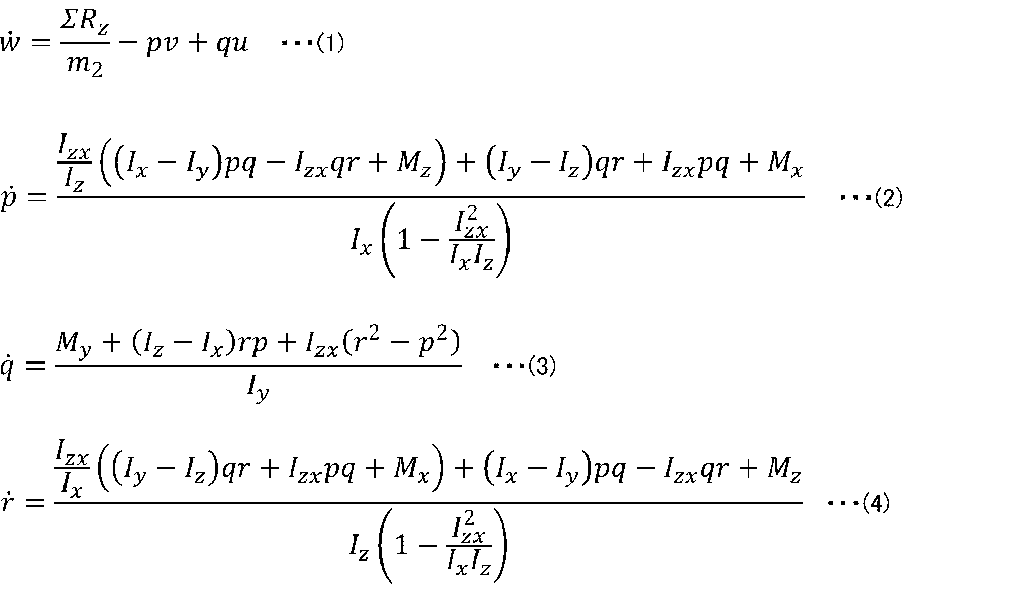
式(1)中、ΣRzは車体200の重心に作用する鉛直方向力、m2は車体200のばね上質量、uは車体200の前後方向のばね上速度、そして、vは車体200の横方向のばね上速度、を表す。
式(2)~(4)中、Izxは車体200のばね上における横方向(例えばy軸)の慣性乗積、Ixは車体200の重心を通るx軸周りの慣性モーメント、Iyは車体200の重心を通るy軸周りの慣性モーメント、そして、Izは車体200の重心を通るz軸周りの慣性モーメント、を表す。また、式(2)~(4)中、Mxは車体200の重心に作用するx軸周りのモーメント、Myは車体200の重心に作用するy軸周りのモーメント、そして、Mzは車体200の重心に作用するz軸周りのモーメント、を表す。

式(5)中、m1iiは任意の車輪のばね下質量、Rziiは各車輪のばね下にかかるサスペンション反力、そしてk1iiは任意の車輪のタイヤばね定数、を表す。

式(6)中、DampViiは、各車輪のサスストローク速度を表し、wiiは、各車輪のばね上におけるサスポイントの上下速度を表す。式(7)中、TireViiは、各車輪におけるタイヤストローク速度を表し、w0iiは、任意の車輪点における路面変位の微分値を表す。wiiは、以下の式(6a)~(6d)で表される。式(6a)~(6d)中、trf、trrは車体200の前後トレッド半長を表し、lf、lrは車体200の前後車軸重心間距離を表す。

<外力/モーメントを表す式>
上記の運動方程式中の外力あるいはモーメントについては、例えば以下に説明する式(8)~(23)で表される。たとえば、サスペンション反力は、以下の式(8)~(11)で表される。
上記の運動方程式中の外力あるいはモーメントについては、例えば以下に説明する式(8)~(23)で表される。たとえば、サスペンション反力は、以下の式(8)~(11)で表される。

式(8)~(11)中、Rzfl,Rzfr,Rzrl,Rzrrは各車輪におけるサスペンション反力を表し、DampFfl,DampFfr,DampFrl,DampFrrは各車輪におけるダンパ減衰力を表す。また、式(8)~(11)中、k2f、k2rは前輪および後輪の懸架ばねのばね定数、C2f、C2rは前輪および後輪に関する後述する車両モデルの安定性を高めるためのパラメータ、そしてkaf、karは前輪および後輪におけるスタビライザの剛性、を表す。
また、車体200の重心に作用する前後方向力ΣRx、車体200の重心に作用する横方向力ΣRy、および重心に作用する鉛直方向力ΣRz、はそれぞれ以下の式(12)~(14)で表される。

式(12)、式(13)中、ΣFx0は、車両900の全タイヤの前後力を表し、ΣFy0は、車両900の全タイヤの横力を表す。

式(15)~(17)中、MxRは、車体200の重心に作用するサスペンションのx軸周りの反力モーメントを表し、MyRは、車体200の重心に作用するサスペンションのy軸周りの反力モーメントを表し、MzRは、車体200の重心に作用するサスペンションのz軸周りの反力モーメントを表す。また、式(15)~(17)中、h1は、車両900の重心から各輪のばね下までのz軸方向距離の平均を表す。

式(18)~(20)中、Mxtireは、車体200の重心に作用するタイヤのx軸周りの反力モーメントを表し、Mytireは、車体200の重心に作用するタイヤのy軸周りの反力モーメントを表し、Mztireは重心に作用するタイヤのz軸周りの反力モーメントを表す。また、R0は、タイヤ半径を表す。なお、Mx、MyおよびMzは、下記式(21)~(23)で表される。

<運動方程式の変形>
本実施形態におけるECU600への入力値は、例えば、以下の行列U1、U2で表すことができる。ここで、U1およびU2はq×1の行列で表されるベクトルであり、U1においてはq=8、U2においてはq=6である。また、ECU600への観測値は、以下の行列Yで表すことができる。ここで、Yはp×1の行列で表されるベクトルであり、例えば本実施形態においてはp=5である。
本実施形態におけるECU600への入力値は、例えば、以下の行列U1、U2で表すことができる。ここで、U1およびU2はq×1の行列で表されるベクトルであり、U1においてはq=8、U2においてはq=6である。また、ECU600への観測値は、以下の行列Yで表すことができる。ここで、Yはp×1の行列で表されるベクトルであり、例えば本実施形態においてはp=5である。

上述した運動方程式は、以下の式(24)および式(25)で表すことができる。

ヤコビ行列(Jx,Ju)を用い、式(24)から下記式(26)を導出し、式(25)から式(27)を導出する。式(26)および式(27)における右辺の最終項は、誤差を表している。

ここで、f(X0,U0)=0、h(X0)=0とすると、式(26)における右辺の第二項、第三項は、それぞれ式(28)、式(29)で表され、式(27)における右辺の第二項は、式(30)で表される。
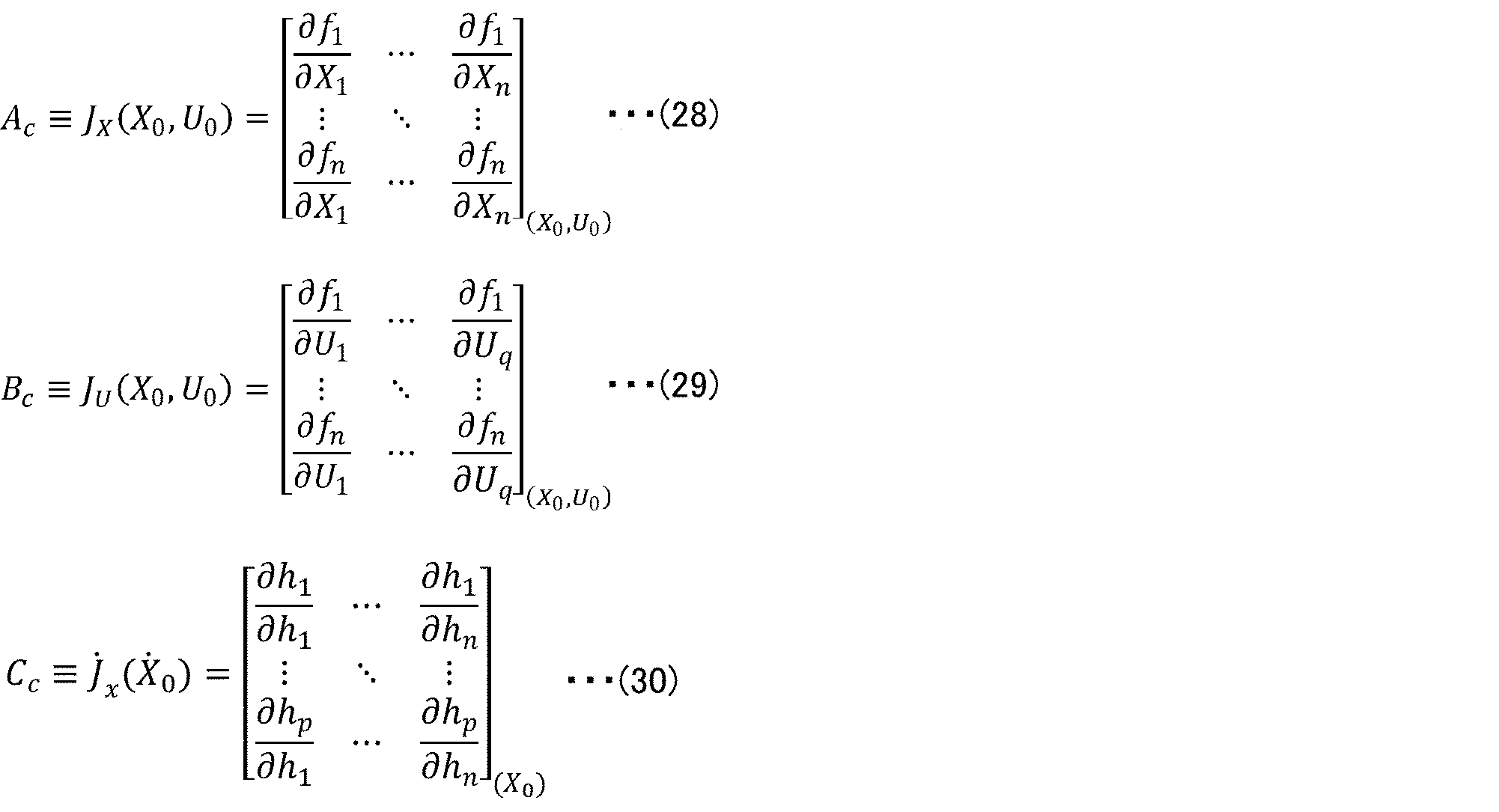
よって、式(24)は、下記式(31)で表される。このように、前述の運動方程式は、線形的に演算される線形システムで表される。ここで、式(31)を離散化すると、下記式(32)、式(33)および、式(34)が導出される。式(32)中、Acは、車両900の固有の特性を表すシステム行列として表される。式(33)中、Bcは、入力による車両900への影響を表す入力行列として表される。式(34)中、Ccは、車両900からの観測量を出力するための観測行列として表される。当該車両モデルは、状態量および上記行列U1、U2から明らかなように車両900の要素を含んでおり、車両全体の挙動を示す単一のモデルとなっている。

<行列の離散化>
Ac、BcおよびCc行列は、前述の通り下記式(32)、式(33)および、式(34)によって離散化される。つまり、Acは離散化されたシステム行列、Bcは離散化された入力行列および、Ccは離散化された観測行列を表す。なお、式(32)中、L-1は逆ラプラス演算処理を表し、sはラプラス演算子を表し、Iは単位行列を表す。また、式(33)中、Δtはサンプル時間を表す。
Ac、BcおよびCc行列は、前述の通り下記式(32)、式(33)および、式(34)によって離散化される。つまり、Acは離散化されたシステム行列、Bcは離散化された入力行列および、Ccは離散化された観測行列を表す。なお、式(32)中、L-1は逆ラプラス演算処理を表し、sはラプラス演算子を表し、Iは単位行列を表す。また、式(33)中、Δtはサンプル時間を表す。

<車両モデル>
本実施形態における車両状態量推定の為の車両モデルは、下記式(35)、式(36)で表すことができる。当該車両モデルは、前述したように、車両900の要素を含む、車両全体の挙動を示す単一のモデルである。ここで、下付きのkは、離散状態における任意のステップを表しており、k-1は、kに対して1ステップ前のステップを表す。
本実施形態における車両状態量推定の為の車両モデルは、下記式(35)、式(36)で表すことができる。当該車両モデルは、前述したように、車両900の要素を含む、車両全体の挙動を示す単一のモデルである。ここで、下付きのkは、離散状態における任意のステップを表しており、k-1は、kに対して1ステップ前のステップを表す。

上記式(35)、式(36)において、Xkハットは車両モデルの状態量、つまり推定車両状態量である。Xkハットは、下記の行列で表される。
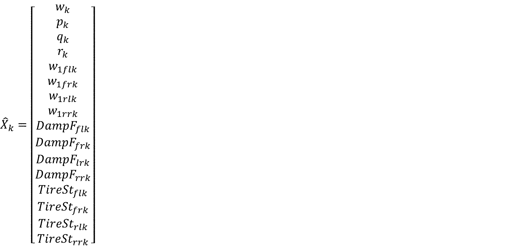
また、Ukハットは入力値であり、例えば下記式のU1kハット、U2kハットで表される。

また、Ykハットは観測量であり、すなわち推定車両観測量である。Ykハットは下記の行列で表される。

[実施形態1]
本実施形態では、前述したロジックに従う状態量を算出し、当該状態量を用いて懸架装置100の動作を制御する。
本実施形態では、前述したロジックに従う状態量を算出し、当該状態量を用いて懸架装置100の動作を制御する。
〔ECUの機能的構成〕
図2は、本発明の実施形態1に係る制御装置の機能的構成の一例を示すブロック図である。
図2は、本発明の実施形態1に係る制御装置の機能的構成の一例を示すブロック図である。
図2に示されるように、ECU(制御装置)600は、接地荷重算出部610、入力量算出部620、第一状態量算出部630、観測量算出部640、第二状態量算出部650およびダンパECU660を備える。また、本実施形態における制御に用いる車両に関する物理量を取得するための取得部として、ECU600には、ヨーレートセンサ350、車輪速センサ320、舵角センサ440、横Gセンサ330および前後Gセンサ340、ならびにRAM601が接続されている。接地荷重算出部610、入力量算出部620、第一状態量算出部630、観測量算出部640および第二状態量算出部650は、状態量算出装置に該当する。
接地荷重算出部610は、接地荷重を算出する。接地荷重とは、車両のばね下への鉛直方向の荷重である。接地荷重算出部610は、慣性荷重算出部611、路面荷重算出部612、接地荷重演算部613および車輪速センサ320が取得した車輪速Vwから車輪速変動ΔVwを算出する車輪速変動算出部614を備えている。
慣性荷重算出部611は、慣性荷重を算出する。慣性荷重は、車両900に作用する慣性力による挙動変化によって生じる接地荷重成分である。たとえば、慣性荷重算出部611は、車輪速センサ320が取得した車輪速Vw、舵角センサ440が取得した操舵角δs、横Gセンサ330が取得した横加速度ay、前後Gセンサ340が取得した前後加速度ax、ならびに、RAM601に格納されている車重m等の車両諸元を入力値として各車輪の慣性荷重dFz0inertiafl,fr,rl,rrを算出する。なお、車両の物理量の前に「d」を伴う場合は、当該物理量の変動または差分を意味する。
路面荷重算出部612は、車輪速、車輪速変動、定常荷重Fz0nomおよび慣性荷重から路面荷重を算出する。路面荷重は、路面の凹凸による接地荷重成分である。たとえば、路面荷重算出部612は、車輪速変動算出部614が算出した車輪速変動ΔVw、慣性荷重算出部611が算出した各車輪の慣性荷重dFz0inertiafl,fr,rl,rr、ならびに、RAM601に格納されている車重m、定常荷重Fz0nomおよび車両諸元等、を入力値として各車輪の路面荷重dFz0roadfl,fr,rl,rrを算出する。
接地荷重演算部613は、慣性荷重および路面荷重から接地荷重を演算する。たとえば、接地荷重演算部613は、慣性荷重算出部611が算出した各車輪の慣性荷重dFz0inertiafl,fr,rl,rr、路面荷重算出部612が算出した各車輪の路面荷重dFz0roadfl,fr,rl,rr、および定常荷重Fz0nom(不図示)を入力値として、各車輪の接地荷重dFz0fl,fr,rl,rrを算出する。
入力量算出部620は、少なくとも前記車両が備えるGセンサのセンサ値を用いて入力量を算出する。たとえば、入力量算出部620は、Gセンサ値、車両重量およびダンパ電流値から入力量を算出する。入力量算出部620は、演算部621、マップ622および入力量構成部623を備えている。
演算部621は、例えば、横Gセンサ330が取得した横加速度ay、前後Gセンサ340が取得した前後加速度ax、ならびに、RAM601に格納されている車重mを入力値として、車体200の重心に作用する前後方向力ΣRxおよび車体200の重心に作用する横方向力ΣRyを算出する。
マップ622は、サスストローク速度およびダンパ電流とダンパ減衰量との相関性を示すものであり、グラフまたは式として表され得る。マップ622は、例えば、後述する各車輪のサスストローク速度DampVfl,fr,rl,rrおよび各車輪のダンパ電流DampCurfl,fr,rl,rrを入力値として、当該入力値に応じた各車輪のダンパ減衰量DampFfl,fr,rl,rrを出力する。ダンパ電流DampCurfl,fr,rl,rrは、ダンパECU640からのフィードバック値である。
入力量構成部623は、演算部621が算出した前後方向力ΣRxおよび横方向力ΣRyと、マップ622が出力したダンパ減衰量DampFfl,fr,rl,rrとを入力値として、入力量を構成する。当該入力量は、例えば、前述した行列U2で表される。
第一状態量算出部630は、入力量算出部620が算出した入力量を前述した車両モデルに入力して車両900の第一状態量を算出する。第一状態量算出部630は、演算部631、633、遅延部632、抽出部634および加算部635を備えている。
演算部631は、入力量構成部623が算出した入力量と入力行列Bとの積を算出する。これにより、車両モデルに対する入力量の影響が、後に算出される第一状態量に反映される。
遅延部632は、後述するステップkの第二状態量X2kハットを一ステップ前のステップk-1の第二状態量X2k-1ハットとする。
演算部633は、遅延部632が生成した第二状態量X2k-1ハットとシステム行列Aとの積を算出する。これにより、車両モデル固有の特性が、後に算出される第一状態量に反映される。
抽出部634は、遅延部632が生成した第二状態量X2k-1ハットから各車輪のサスストローク速度DampVfl,fr,rl,rrを算出する。たとえば、抽出部634は、第二状態量X2k-1ハットから各車輪のサスストロークの成分を抽出し、抽出した成分を適宜に微分し、あるいは適当なゲインによって調整して、各車輪のサスストローク速度DampVfl,fr,rl,rrを算出する。得られる算出値は、上記サスストローク速度で構成される4×1行列で表され、前述のマップ622の入力値となる。
加算部635は、演算部631が算出した入力量と入力行列Bとの積と、演算部633が算出した第二状態量X2k-1ハットとシステム行列Aとの積とを足し合わせて第一状態量X’2kハットを算出する。
観測量算出部640は、接地荷重算出部610が算出した接地荷重とタイヤのばね定数ゲインとから観測量を算出する。観測量算出部640は、タイヤストローク算出部641および観測量構成部642を備えている。
各車輪のタイヤストローク変位TireStiiは、下記式(37)で表される。タイヤストローク算出部641は、接地荷重演算部613が算出した各車輪の接地荷重dFz0fl,fr,rl,rrとタイヤばね定数ゲインGとから、各車輪のタイヤストロークTireStfl,fr,rl,rrを算出する。タイヤストローク変位は、タイヤの変化量の一態様である。

観測量構成部642は、現在のタイヤの変化量を含む観測量を構成する。たとえば、観測量構成部642は、タイヤストローク算出部641が算出したタイヤストローク変位と、ヨーレートセンサ350が取得したヨーレートの検出値とを入力値として、観測量Ykを構成する。タイヤストローク変位は、タイヤ半径の変化量であり、タイヤの変化量の一態様である。観測量Ykは、例えば、5×1行列であり、以下のように表される。ここで、添え字下付きのsensは、観測量であることを意味する。

ここで、rsens kはヨーレートセンサ350の検出値であり、TireStii sens kはタイヤストローク算出部641が算出したタイヤストローク変位である。
なお、観測量算出部640は、タイヤストローク算出部641を備えず、観測量構成部642が、接地荷重演算部613が演算した接地荷重を直接、観測量として構成する構成としてもよい。
第二状態量算出部650は、観測量算出部640が算出した観測量Ykを用いて、第一状態量算出部630が算出した車両900の第一状態量X’2kハットを補正することにより車両900の第二状態量をX2kハット算出する。第二状態量算出部650は、演算部651、653、減算部652および加算部654を備えている。
演算部651は、既出の状態量から観測量を算出する。たとえば、演算部651は、遅延部632が出力したn×1行列で表されるX2k-1ハットに、p×n行列で表される出力行列Cを乗じて、状態量から予測される予測観測量Ykハットを算出する。
減算部652は、観測量構成部642が構成した観測量Ykから、演算部651が算出した推定観測量Ykハットを減算して観測量の減算値を算出する。Ykは、実測に基づく観測量であり、Ykハットは推定された観測量と言える。
演算部653は、減算部652が算出した観測量の減算値にカルマンゲインKを乗じる。カルマンゲインKは、カルマンフィルタのゲインである。
加算部654は、加算部635が算出した第一状態量X’2kハットと、実測に基づく観測量から推定観測量を引いた差分にカルマンゲインKを乗じた数値とを足し合わせる。こうして補正された状態量である第二状態量X2kハットが算出される。第二状態量X2kハットは、前述した遅延部632に出力される。
このように、第二状態量算出部650は、カルマンゲインをさらに用いて第一状態量X’2kハットを補正している。したがって、第二状態量算出部650は、カルマンフィルタリングブロックを構成している、とも言える。
ダンパECU660は、車両900の状態量の算出値を用いて懸架装置100を制御する。ダンパECU660は、車両900が備える装置を制御する制御部に該当する。ダンパECU670は、例えば、遅延部632から出力される第二状態量X2k-1ハット、および、抽出部634が第二状態量X2k-1ハットから抽出した各車輪のサスストローク速度DampVfl,fr,rl,rr、を入力値として、懸架装置100の動作を、例えばスカイフック制御により制御する。
〔作用効果〕
以上の説明から明らかなように、本実施形態において、ECU600は、前述の接地荷重算出部610、入力量算出部620、第一状態量算出部630、観測量算出部640および第二状態量算出部650を備える。ECU600では、接地荷重に基づく観測量が変位、つまり長さの単位で表現され、当該観測量を用いて状態量が算出される。一方で、懸架装置100の制御を行う場合、懸架装置100の制御量は、通常、制御対象となる物の変位情報、すなわち長さの単位で表される物理量、で表される。したがって、観測量が制御量と同じ次元の情報として表されることから、上記の制御において当該観測量を用いた演算結果による状態量の制御結果が安定する。変位情報を表さない、つまり長さの単位以外の観測量を上記のような制御の演算に用いる場合では、演算結果に基づいて制御される制御対象物の変位による挙動が定まらないことがあり、その結果、制御のための演算結果が収束せずに発散することがある。したがって、このような長さの単位以外を制御の演算に用いる場合では、発散してしまった演算結果を用いることにより制御精度等の悪化が発生してしまうことがある。また、それを防ぐためには、常に演算結果が所定の範囲に収まるように、系全体をオフセットさせる処理など、別な手段を講じる必要がある。よって、本実施形態では、位置情報を表さない単位の観測量に基づいて状態量を算出する場合に比べて、より単純な構成で状態量の算出を安定させることが可能である。
以上の説明から明らかなように、本実施形態において、ECU600は、前述の接地荷重算出部610、入力量算出部620、第一状態量算出部630、観測量算出部640および第二状態量算出部650を備える。ECU600では、接地荷重に基づく観測量が変位、つまり長さの単位で表現され、当該観測量を用いて状態量が算出される。一方で、懸架装置100の制御を行う場合、懸架装置100の制御量は、通常、制御対象となる物の変位情報、すなわち長さの単位で表される物理量、で表される。したがって、観測量が制御量と同じ次元の情報として表されることから、上記の制御において当該観測量を用いた演算結果による状態量の制御結果が安定する。変位情報を表さない、つまり長さの単位以外の観測量を上記のような制御の演算に用いる場合では、演算結果に基づいて制御される制御対象物の変位による挙動が定まらないことがあり、その結果、制御のための演算結果が収束せずに発散することがある。したがって、このような長さの単位以外を制御の演算に用いる場合では、発散してしまった演算結果を用いることにより制御精度等の悪化が発生してしまうことがある。また、それを防ぐためには、常に演算結果が所定の範囲に収まるように、系全体をオフセットさせる処理など、別な手段を講じる必要がある。よって、本実施形態では、位置情報を表さない単位の観測量に基づいて状態量を算出する場合に比べて、より単純な構成で状態量の算出を安定させることが可能である。
また、本実施形態では、汎用センサの取得値から観測量が算出され、このような観測量が状態量の補正に用いられる。すなわち、本実施形態では、当該観測量で補正された状態量が算出される。したがって、本実施形態では、観測量による状態量の補正を行わない場合に比べて、状態量のよりよい推定結果が得られる。したがって、本実施形態によれば、前述の観測量を用いない場合に比べて、車両の状態量を高い精度で算出することができる。
さらに、本実施形態では、センサ値として汎用センサの取得値を用いて観測量が算出される。よって、特別なセンサを用いずとも、上記のように高い精度で車両の状態量を算出することが可能である。
本実施形態では、観測量は現在のタイヤの変化量を含む。このため、走行している車両の状態を表す物理量として適している。したがって、この構成は、車両の走行状態を高い精度で制御するための状態量としてより効果的である。
また、本実施形態では、タイヤの変化量は、タイヤ半径の変化量であり、すなわちタイヤストローク変位である。タイヤストローク変位は、タイヤの変化量の中でも状態量の算出により多く寄与することが期待される。よって、この構成は、状態量の算出における誤差を抑制する観点からより一層効果的である。
また、本実施形態では、第二状態量算出部650は、カルマンフィルタリングブロックを構成しており、カルマンゲインをさらに用いたカルマンフィルタリングによって車両900の第一状態量を補正する。このように、本実施形態では、カルマンフィルタによって補正された、より好適な観測量に基づいて第一状態量が算出される。よって、上記の構成は、このような補正を含まない観測量を用いて状態量を算出する場合に比べて、適切に補正された観測量に基づいてより適切に補正された状態量を算出する観点からより一層効果的である。
また、本実施形態において、接地荷重算出部610は、前述の慣性荷重算出部611、路面荷重算出部612および接地荷重演算部613を備えている。したがって、汎用センサの検出値から接地荷重を正確に推定することが可能である。よって、この構成は、特別なセンサを用いることなく観測量の精度を高める観点からより一層効果的である。
また、本実施形態の車両モデルは、車両全体の挙動を表現できる単一のモデルを用いている。このため、全車輪に及ぼされる車両全体の影響が状態量の算出に反映される。たとえば、任意の車輪に及ぼされた影響が、車体や別の車輪等に更なる影響を及ぼしている状況が挙げられる。状態量の算出を車輪毎で完結させる一輪モデルを車輪数の分だけ組み合わせて用いる場合では、このような状況において算出した状態量は、実際の車両の挙動とはかけ離れてしまう場合がある。したがって、この構成は、状態量の算出を車輪毎で完結させる一輪モデルを用いる場合に比べて、車両の状態量を適切に算出できる状況の範囲を広げる観点からより一層効果的である。
また、本実施形態では、ECU600は、上記の状態量算出装置と、前述の制御部としてのダンパECU660とを備える。したがって、上記のように算出した状態量を用いて車両900が備える装置を適切に制御することが可能であり、その結果、走行する車両900の走行状態が適切に制御される。したがって、この構成は、上記の状態量を用いずに制御する場合に比べて、車両の走行安定性をより一層高めることができる。
また、本実施形態では、車両900が備える装置は、例えば電子制御式ステアリング装置としての懸架装置100である。この構成によれば、走行している車両の懸架装置をより適切に制御することができる。
さらに、本実施形態では、車両900は、上記のECU600を備えている。したがって、車両900の走行状態が適切に制御される。よって、この構成によれば、走行安定性が高められる車両900を提供することができる。
また、本実施形態では、車両のばね下への鉛直方向の荷重である接地荷重を算出するステップと、Gセンサ値、車両重量およびダンパ電流値から入力量を算出するステップと、前記入力量を算出するステップで算出した前記入力量を車両モデルに入力して、第一の前記車両の状態量を算出するステップと、前記接地荷重を算出するステップで算出した前記接地荷重とタイヤのばね定数ゲインとから観測量を算出するステップと、前記観測量を算出するステップで算出した前記観測量を用いて、前記第一の前記車両の状態量を算出するステップで算出した前記第一の車両の状態量を補正することにより、第二の前記車両の状態量を算出するステップとを含む、状態量の算出方法が実施される。したがって、前述したように、車両900の状態量を高い精度で算出することができる。
〔実施形態2〕
本発明の他の実施形態について、以下に説明する。なお、説明の便宜上、上記実施形態にて説明した部材と同じ機能を有する部材については、同じ符号を付記し、その説明を繰り返さない。
本発明の他の実施形態について、以下に説明する。なお、説明の便宜上、上記実施形態にて説明した部材と同じ機能を有する部材については、同じ符号を付記し、その説明を繰り返さない。
本実施形態では、ECU600は、車輪速補正部をさらに備える。車輪速補正部は、例えば、車輪速センサ320が取得した車輪速Vwを入力値とし、車輪速Vwからサスペンションジオメトリの変化による車輪速変動成分を除去することにより車輪速を補正する。車輪速補正部は、このように補正した車輪速Vwを接地荷重算出部610に出力する。接地荷重算出部610は、補正された車輪速Vwを用いて、前述のようにして接地荷重を算出する。車輪速補正部は、車輪速Vwに代えて車輪速差ΔVwを補正してもよい。
たとえば、サスペンションの軸方向が鉛直方向に対して斜めである場合、サスペンションが伸縮することにより、タイヤは、当該軸方向の力を受け、車輪速は、当該力に応じて変動する。車輪速センサ320は、上記の力に応じて変動する車輪速を検出するが、前述した状態量の算出では、このようなサスペンションの作動に伴う車輪速の変動分は、ノイズとなる。車輪速補正部は、車輪速センサ320の取得値から、このようなノイズとなる成分を除く。よって、本実施形態では、接地荷重算出部610は、当該ノイズが除かれた車輪速Vwを用いて接地荷重を算出することができ、観測量算出部640では、当該接地荷重を用いて各車輪のタイヤストロークが算出され得る。このように、本実施形態では、状態量を算出する前にノイズとなる成分が除去される。
本実施形態では、ECU600は、サスペンションジオメトリの変化による車輪速変動成分を除去することにより車輪速を補正する車輪速補正部をさらに備える。この構成は、ECU600が当該車輪速補正部を備えない場合に比べて、高い精度の状態量を算出する観点からより一層効果的である。
〔実施形態3〕
本発明の他の実施形態について、以下に説明する。なお、説明の便宜上、上記実施形態にて説明した部材と同じ機能を有する部材については、同じ符号を付記し、その説明を繰り返さない。
本発明の他の実施形態について、以下に説明する。なお、説明の便宜上、上記実施形態にて説明した部材と同じ機能を有する部材については、同じ符号を付記し、その説明を繰り返さない。
本実施形態では、ECU600は、理想の車両状態を算出する規範モデルをさらに備えている。当該規範モデルは、例えば車両900の走行状態に関する一以上のモデルである。本実施形態では、例えば第一モデルおよび第二モデルである。第一モデルは走行性をより重視するモデルであり、第二モデルは、乗り心地をより重視するモデルである。第一モデルおよび第二モデルは、前述した状態量の算出で用いられる適当な形態となっている。たとえば、これらのモデルは、算出値に対するゲイン処理におけるゲインの形態で、あるいはマップの形態で表され得る。これらのモデルは、例えば、第一モデル用のゲイン、第二モデル用のマップなどの形態でRAM601に格納されている。
また、ECU600は、車両900の運転者からの規範モデルの指示を受けるモデル入力部をさらに備えていてよい。当該モデル入力部が、第一モデルおよび第二モデルのいずれかを選択する運転者の操作を受け付けると、ECU600は、当該操作に応じて規範モデルを選択し、選択したモデルに対応するゲインあるいはマップを用いて状態量を算出する。
ダンパECU660は、理想の車両状態と状態量との差を減少させるように懸架装置100を制御する。たとえば、ダンパECU660は、第一モデルに基づいて状態量が算出される場合では、タイヤの接地感をより高めるように、乗り心地を高めるための制御量よりも、操作安定性を高めるための制御量を多くして、懸架装置100を制御する。また、第二モデルに基づいて状態量が算出される場合では、走行時における車両900の搭乗者の快適さがより高められるように、操作安定性を高めるための制御量よりも、乗り心地を高めるための制御量を多くして、懸架装置100を制御する。
本実施形態では、ECU600が上記の規範モデルをさらに備え、ダンパECU660が理想の車両状態と状態量との差を減少させるように懸架装置100を制御する。この構成は、前述のような高い精度で算出される状態量を用いて所望の車両状態を実現する観点からより一層効果的である。
〔実施形態4〕
本発明の他の実施形態について、以下に説明する。なお、説明の便宜上、上記実施形態にて説明した部材と同じ機能を有する部材については、同じ符号を付記し、その説明を繰り返さない。
本発明の他の実施形態について、以下に説明する。なお、説明の便宜上、上記実施形態にて説明した部材と同じ機能を有する部材については、同じ符号を付記し、その説明を繰り返さない。
図3は、本発明の実施形態3に係る制御装置の機能的構成の一例を示すブロック図である。実施形態3のECU600aは、入力量算出部620に代えて670を備え、観測量算出部640および第二状態量算出部650を備えない点で、前述の実施形態のECU600と異なる。たとえば、図3に示されるように、ECU600aは、接地荷重算出部610、タイヤ変化量算出部670、第一状態量算出部630およびダンパECU660を備えている。また、ECU600aには、車輪速センサ320、舵角センサ440、横Gセンサ330、前後Gセンサ340およびRAM601が接続されている。
タイヤ変化量算出部670のタイヤの変化量を算出する。タイヤの変化量は、例えば、タイヤの半径の変化量であるタイヤストローク変位である。タイヤ変化量算出部670は、タイヤストローク算出部641、マップ622および演算部671を備えている。
演算部671は、タイヤストローク算出部641が算出した各車輪のタイヤストロークTireStfl,fr,rl,rrと、マップ622が出力したダンパ減衰量DampFfl,fr,rl,rrとを、前述した行列U1kに入力して行列Ukを得る。
第一状態量算出部630において、演算部631は、演算部671が算出した行列Ukに前述した入力行列Bを乗じる。入力行列Bは、入力によるシステム(運動方程式)への影響を表す行列である。
遅延部632は、状態量Xkハットを一ステップ前のものにする。実施形態4にいて、状態量をX1kハットとし、ステップk-1の状態量X1k-1ハットとする。
演算部633は、状態量X1k-1ハットとシステム行列Aとの積を算出する。
抽出部634は、前述したように、状態量X1k-1ハットから各車輪のサスストロークの成分を抽出し、適宜に調整して、各車輪のサスストローク速度DampVfl,fr,rl,rrを算出する。得られる算出値は、マップ622の入力値となる。
加算部635は、行列Ukと入力行列Bとの積と、状態量X1k-1ハットとシステム行列Aとの積とを足し合わせ、状態量X1kハットを算出する。
ダンパECU660は、車両900の状態量の算出値を用いて懸架装置100を制御する。ダンパECU660は、遅延部632から状態量X1k-1ハットを取得し、抽出部634から各車輪のサスストローク速度DampVfl,fr,rl,rrを取得する。これらの取得値に応じて、懸架装置100の動作を、例えばスカイフック制御により制御する。また、各車輪のダンパ電流DampCurfl,fr,rl,rrをマップ622に出力する。
以上の説明から明らかなように、本実施形態において、ECU600aは、前述の接地荷重算出部610、タイヤ変化量算出部670および第一状態量算出部630を備えている。ECU600aでは、接地荷重に基づいてタイヤ変化量が状態量の算出に用いられる。したがって、前述の実施形態と同様に、変位、つまり長さの単位で表現される算出値であるタイヤ変化量に基づいて状態量を算出するため、状態量の算出結果が安定する。よって、本実施形態でも、前述の実施形態と同様に、変位情報を表さない、つまり長さの単位以外の観測量に基づいて状態量を算出する場合に比べて、状態量の算出を安定させることが可能である。
また、本実施形態では、センサ値として汎用センサの取得値を用いて観測量が算出される。よって、特別なセンサを用いずとも、上記のように高い精度で車両の状態量を算出することが可能である。
本実施形態では、タイヤの変化量がタイヤストローク変位である。このため、前述した実施形態と同様に、この構成は、状態量の算出における誤差を抑制する観点からより一層効果的である。
また、本実施形態において、接地荷重算出部610は、前述の慣性荷重算出部611、路面荷重算出部612および接地荷重演算部613を備えている。したがって、汎用センサの検出値から接地荷重を正確に推定することが可能である。よって、この構成は、特別なセンサを用いることなく接地荷重およびタイヤ変化量を算出することができ、より高い精度で状態量を算出することが可能である。
また、本実施形態、の車両モデルは、車両全体の挙動を表現できる単一のモデルを用いている。このため、全車輪に及ぼされる車両全体の影響が状態量の算出に反映される。たとえば、任意の車輪に及ぼされた影響が、車体や別の車輪等に更なる影響を及ぼしている状況が挙げられる。状態量の算出を車輪毎で完結させる一輪モデルを車輪数の分だけ組み合わせて用いる場合では、このような状況において算出した状態量は、実際の車両の挙動とはかけ離れてしまう場合がある。したがって、この構成は、前述した実施形態と同様に、状態量の算出を車輪毎で完結させる一輪モデルを用いる場合に比べて、車両の状態量を適切に算出できる状況の範囲を広げる観点からより一層効果的である。
また、本実施形態では、ECU600aは、さらにダンパECU660を備える。したがって、この構成は、前述した実施形態と同様に、上記の状態量を用いずに制御する場合に比べて、車両の走行安定性をより一層高めることができる。
また、本実施形態では、車両900が備える装置は、例えば電子制御式ステアリング装置としての懸架装置100である。よって、この構成によれば、前述した実施形態と同様に、走行している車両の懸架装置をより適切に制御することができる。
さらに、本実施形態では、車両900は、上記のECU600を備えている。したがって、この構成によれば、前述した実施形態と同様に、走行安定性が高められる車両900を提供することができる。
〔実施形態5〕カメラで接地荷重を推定
本発明の他の実施形態について、以下に説明する。なお、説明の便宜上、上記実施形態にて説明した部材と同じ機能を有する部材については、同じ符号を付記し、その説明を繰り返さない。
本発明の他の実施形態について、以下に説明する。なお、説明の便宜上、上記実施形態にて説明した部材と同じ機能を有する部材については、同じ符号を付記し、その説明を繰り返さない。
本実施形態のECUは、車両900が進行方向の路面を撮影可能なカメラを搭載し、路面荷重算出部612が、当該カメラが撮影した映像に基づいて路面荷重を算出する以外は、前述した実施形態と同様である。
本実施形態において、上記カメラは、車両900の進行方向の路面を撮影する。路面荷重算出部612は、撮影された路面の凹凸のデータを取得する。また、路面荷重算出部612は、車両900の現在の走行状態、センサの取得値およびRAM601に格納された車両諸元に基づき、撮影した路面を走行する時の各車輪における各車輪の路面荷重dFz0roadfl,fr,rl,rrを算出する。
上記のカメラは、車両900の進行方向における凹凸などの路面状態を撮影可能であればよく、たとえば、ドライブレコーダが有するカメラであってもよい。
本実施形態では、進行方向の路面の画像から路面荷重を推定することから、状態量を予測することができ、実際に路面の特定箇所(撮影した箇所)を通過する前に、当該特定箇所を通過しているときの状態量を予測することが可能である。したがって、上記の構成は、前述した実施形態に比べて、状態量に基づく車両の走行状態における制御の遅れの発生を防止することができる、という効果を奏す。本実施形態のECUは、前述の実施形態の効果のうちの路面荷重算出部612以外の構成に応じた効果をさらに奏する。
〔実施形態6〕
本発明の他の実施形態について、以下に説明する。なお、説明の便宜上、上記実施形態にて説明した部材と同じ機能を有する部材については、同じ符号を付記し、その説明を繰り返さない。
本発明の他の実施形態について、以下に説明する。なお、説明の便宜上、上記実施形態にて説明した部材と同じ機能を有する部材については、同じ符号を付記し、その説明を繰り返さない。
本実施形態のECUは、ステアリングECUをさらに備える以外は、前述の実施形態と同様の構成を備える。
ステアリングECUは、ECUが算出する状態量Xkハット(またはXk-1ハット)に基づいて、トルク印加部460に供給するステアリング制御量を調整することにより、ステアリングシャフト420に印加するアシストトルク又は反力トルクの大きさを制御する。
本実施形態では、前述した状態量に基づいて、車両900が操舵に応じて好ましい挙動を行うように、サスペンションを制御することが可能である。また、本実施形態では、前述した状態量に基づいて、サスペンションからの出力値またはサスペンション周りにおけるセンサの取得値を参照して、搭乗者に好ましい感覚(例えば、乗り心地および操舵安定性など)を提供するようにサスペンションの動作を制御する。
以上の説明から明らかなように、本実施形態は、ダンパECUに加えてステアリングECUをさらに備える。よって、車両900の走行安定性および操舵安定性の両方をより一層高めることができる。また、本実施形態は、前述の実施形態の効果のうちのステアリングECU以外の構成に応じた効果をさらに奏する。
〔実施形態7〕
本発明の他の実施形態について、以下に説明する。なお、説明の便宜上、上記実施形態にて説明した部材と同じ機能を有する部材については、同じ符号を付記し、その説明を繰り返さない。
本発明の他の実施形態について、以下に説明する。なお、説明の便宜上、上記実施形態にて説明した部材と同じ機能を有する部材については、同じ符号を付記し、その説明を繰り返さない。
本実施形態のECUは、ステアリングECUと動力伝達ECUとを備えている以外は、前述の実施形態と同様の構成を備える。
動力伝達ECUは、ECUが算出する状態量Xkハット(またはXk-1ハット)に基づいて、車両900の車輪に伝達すべきエンジン500の駆動力の分配量を、前後車輪間あるいは左右車輪間で調整することにより、当該駆動力による各車輪における回転数を制御する。ステアリングECUについては、実施形態6で説明したとおりである。
本実施形態では、前述した状態量に基づいて、車両900が操舵に応じて好ましい挙動を行うように、前後車輪間または左右車輪間でのエンジン駆動力の配分を制御することが可能である。よって、本実施形態によれば、操舵安定性と走行性の両方を向上させることが可能である。走行性向上の一例としては、エンジン駆動力の左右車輪間への配分により車体にヨーを発生させ、アンダーステアあるいはオーバーステアを抑制して車両の旋回能力を高めることが挙げられる。また、本実施形態は、前述の実施形態の効果のうちの動力伝達ECU以外の構成に応じた効果をさらに奏する。
〔ソフトウェアによる実現例〕
本発明における状態量算出装置または制御装置の制御ブロック(特にECU600、600a)は、集積回路(ICチップ)等に形成された論理回路(ハードウェア)によって実現してもよいし、ソフトウェアによって実現してもよい。
本発明における状態量算出装置または制御装置の制御ブロック(特にECU600、600a)は、集積回路(ICチップ)等に形成された論理回路(ハードウェア)によって実現してもよいし、ソフトウェアによって実現してもよい。
後者の場合、状態量算出装置または制御装置は、各機能を実現するソフトウェアであるプログラムの命令を実行するコンピュータを備えている。このコンピュータは、例えば1つ以上のプロセッサを備えていると共に、上記プログラムを記憶したコンピュータ読み取り可能な記録媒体を備えている。そして、上記コンピュータにおいて、上記プロセッサが上記プログラムを上記記録媒体から読み取って実行することにより、本発明の目的が達成される。
上記プロセッサとしては、例えばCPU(Central Processing Unit)を用いることができる。上記記録媒体としては、「一時的でない有形の媒体」、例えば、ROM(Read Only Memory)等の他、テープ、ディスク、カード、半導体メモリ、プログラマブルな論理回路などを用いることができる。また、上記プログラムを展開するRAM(Random Access Memory)などをさらに備えていてもよい。
また、上記プログラムは、該プログラムを伝送可能な任意の伝送媒体(通信ネットワークや放送波等)を介して上記コンピュータに供給されてもよい。なお、本発明の一態様は、上記プログラムが電子的な伝送によって具現化された、搬送波に埋め込まれたデータ信号の形態でも実現され得る。
本発明は上述した各実施形態に限定されるものではなく、請求項に示した範囲で種々の変更が可能であり、異なる実施形態にそれぞれ開示された技術的手段を適宜組み合わせて得られる実施形態についても本発明の技術的範囲に含まれる。
100 懸架装置
200 車体
300、300A、300B、300C、300D 車輪
310、310A、310B、310C、310D タイヤ
320 車輪速センサ
330 横Gセンサ
340 前後Gセンサ
350 ヨーレートセンサ
410 操舵部材
420 ステアリングシャフト
430 トルクセンサ
440 舵角センサ
460 トルク印加部
470 ラックピニオン機構
480 ラック軸
500 エンジン
510 エンジントルクセンサ
520 エンジン回転数センサ
530 ブレーキ圧センサ
600、600a ECU
601 RAM
610 接地荷重算出部
611 慣性荷重算出部
612 路面荷重算出部
613 接地荷重演算部
620 入力量算出部
621、631、633、651、653、671 演算部
622 マップ
623 入力量構成部
630 第一状態量算出部
632 遅延部
634 抽出部
635、654 加算部
640 観測量算出部
641 タイヤストローク算出部
642 観測量構成部
650 第二状態量算出部
652 減算部
670 タイヤ変化量算出部
700 発電装置
800 バッテリ
900 車両
Claims (13)
- 車両のばね下への鉛直方向の荷重である接地荷重を算出する接地荷重算出部と、
前記接地荷重算出部が算出した前記接地荷重とタイヤのばね定数ゲインとから、現在のタイヤの変化量を算出するタイヤ変化量算出部と、
前記タイヤ変化量算出部が算出した前記タイヤの変化量を車両モデルに入力し、前記車両の状態量を算出する状態量算出部と、
を備える状態量算出装置。 - 車両のばね下への鉛直方向の荷重である接地荷重を算出する接地荷重算出部と、
少なくとも前記車両が備えるGセンサのセンサ値を用いて入力量を算出する入力量算出部と、
前記入力量算出部が算出した前記入力量を車両モデルに入力して、第一の前記車両の状態量を算出する第一状態量算出部と、
前記接地荷重算出部が算出した前記接地荷重とタイヤのばね定数ゲインとから観測量を算出する観測量算出部と、
前記観測量算出部が算出した前記観測量を用いて、前記第一状態量算出部が算出した前記第一の車両の状態量を補正することにより第二の前記車両の状態量を算出する第二状態量算出部と、
を備える状態量算出装置。 - 車両のばね下への鉛直方向の荷重である接地荷重を算出する接地荷重算出部と、
少なくとも前記車両が備えるGセンサのセンサ値を用いて入力量を算出する入力量算出部と、
前記入力量算出部が算出した前記入力量を車両モデルに入力して、第一の前記車両の状態量を算出する第一状態量算出部と、
前記接地荷重算出部が算出した前記接地荷重を用いて観測量を構成する観測量構成部と、
前記観測量構成部が構成した前記観測量を用いて、前記第一状態量算出部が算出した前記第一の車両の状態量を補正することにより第二の前記車両の状態量を算出する第二状態量算出部と、
を備える状態量算出装置。 - 前記観測量は、現在のタイヤの変化量を含む、請求項2に記載の状態量算出装置。
- 前記タイヤの変化量は、タイヤ半径の変化量である、請求項1または4に記載の状態量算出装置。
- 前記第二状態量算出部は、カルマンフィルタリングブロックを構成し、カルマンゲインをさらに用いたカルマンフィルタリングによって前記第一の車両の状態量を補正する、請求項2~4のいずれか一項に記載の状態量算出装置。
- 前記接地荷重算出部は、
慣性力による前記車両の挙動の変化によって生じる接地荷重成分である慣性荷重を算出する慣性荷重算出部と、
車輪速変動、定常値および前記慣性荷重から路面の凹凸による接地荷重成分である路面荷重を算出する路面荷重算出部と、
前記慣性荷重および前記路面荷重から前記接地荷重を演算する接地荷重演算部と、をさらに備える、請求項1~6のいずれか一項に記載の状態量算出装置。 - サスペンションジオメトリの変化による車輪速変動成分を除去することにより車輪速を補正する車輪速補正部をさらに備える、請求項7に記載の状態量算出装置。
- 前記車両モデルは、車両全体の挙動を示す単一のモデルである、請求項1~8のいずれか一項に記載の状態量算出装置。
- 請求項1~9のいずれか一項に記載の状態量算出装置と、
前記状態量算出装置が算出した前記車両の状態量を用いて前記車両が備える装置を制御する制御部と、
を備える制御装置。 - 前記車両が備える装置は、電子制御式駆動力伝達装置、電子制御式サスペンションおよび電子制御式ステアリング装置からなる群から選ばれる一以上の装置である、請求項10に記載の制御装置。
- 理想の車両状態を算出する規範モデルをさらに備え、
前記制御部は、理想の車両状態と状態量との差を減少させるように、前記車両が備える装置を制御する、
請求項10または11に記載の制御装置。 - 請求項10~12のいずれか一項に記載の制御装置を備える車両。
Priority Applications (3)
| Application Number | Priority Date | Filing Date | Title |
|---|---|---|---|
| DE112019007748.1T DE112019007748T5 (de) | 2019-09-26 | 2019-11-25 | Zustandsgrößen-Berechnungsvorrichtung, Steuervorrichtung und Fahrzeug |
| CN201980099862.5A CN114340969B (zh) | 2019-09-26 | 2019-11-25 | 状态量计算装置、控制装置及车辆 |
| US17/666,910 US12528449B2 (en) | 2019-09-26 | 2022-02-08 | State quantity calculation device, control device, and vehicle |
Applications Claiming Priority (2)
| Application Number | Priority Date | Filing Date | Title |
|---|---|---|---|
| JP2019-175961 | 2019-09-26 | ||
| JP2019175961A JP6810779B1 (ja) | 2019-09-26 | 2019-09-26 | 状態量算出装置、制御装置および車両 |
Related Child Applications (1)
| Application Number | Title | Priority Date | Filing Date |
|---|---|---|---|
| US17/666,910 Continuation US12528449B2 (en) | 2019-09-26 | 2022-02-08 | State quantity calculation device, control device, and vehicle |
Publications (1)
| Publication Number | Publication Date |
|---|---|
| WO2021059544A1 true WO2021059544A1 (ja) | 2021-04-01 |
Family
ID=73993046
Family Applications (1)
| Application Number | Title | Priority Date | Filing Date |
|---|---|---|---|
| PCT/JP2019/045907 Ceased WO2021059544A1 (ja) | 2019-09-26 | 2019-11-25 | 状態量算出装置、制御装置および車両 |
Country Status (5)
| Country | Link |
|---|---|
| US (1) | US12528449B2 (ja) |
| JP (1) | JP6810779B1 (ja) |
| CN (1) | CN114340969B (ja) |
| DE (1) | DE112019007748T5 (ja) |
| WO (1) | WO2021059544A1 (ja) |
Families Citing this family (7)
| Publication number | Priority date | Publication date | Assignee | Title |
|---|---|---|---|---|
| US12434529B2 (en) * | 2020-07-08 | 2025-10-07 | Hitachi Astemo, Ltd. | Vehicle control apparatus and suspension system |
| US11993122B1 (en) | 2022-02-14 | 2024-05-28 | Zoox, Inc | Updating vehicle models for improved suspension control |
| US12030359B1 (en) | 2022-02-14 | 2024-07-09 | Zoox, Inc. | Active suspension system using modal expansion |
| US11938776B1 (en) * | 2022-02-14 | 2024-03-26 | Zoox, Inc. | Multiple model active suspension control |
| JP7879792B2 (ja) * | 2022-11-18 | 2026-06-24 | カヤバ株式会社 | 接地荷重推定装置、サスペンション装置および接地荷重推定プログラム |
| CN115959140B (zh) * | 2023-03-16 | 2023-06-02 | 安徽蔚来智驾科技有限公司 | 基于卡尔曼滤波的车辆纵向阻力获取方法、装置及车辆 |
| DE102023123804B3 (de) | 2023-09-05 | 2024-11-07 | Dr. Ing. H.C. F. Porsche Aktiengesellschaft | Fahrzeug und Betriebsverfahren |
Citations (3)
| Publication number | Priority date | Publication date | Assignee | Title |
|---|---|---|---|---|
| JP2016168887A (ja) * | 2015-03-11 | 2016-09-23 | トヨタ自動車株式会社 | 車体状態量推定装置 |
| JP2019089504A (ja) * | 2017-11-16 | 2019-06-13 | 株式会社ショーワ | 車両状態推定装置、制御装置、サスペンション制御装置、サスペンション装置、ステアリング制御装置、及びステアリング装置 |
| JP2019119380A (ja) * | 2018-01-10 | 2019-07-22 | 日立オートモティブシステムズ株式会社 | 車両、車両運動状態推定装置および車両運動状態推定方法 |
Family Cites Families (8)
| Publication number | Priority date | Publication date | Assignee | Title |
|---|---|---|---|---|
| JP5776375B2 (ja) | 2011-06-29 | 2015-09-09 | 日産自動車株式会社 | サスペンション制御装置 |
| EP2808212B1 (en) * | 2012-01-25 | 2019-02-20 | Nissan Motor Co., Ltd | Vehicle control system and vehicle control method |
| WO2014002444A1 (ja) | 2012-06-29 | 2014-01-03 | 本田技研工業株式会社 | サスペンション制御装置 |
| JP5740358B2 (ja) * | 2012-06-29 | 2015-06-24 | 本田技研工業株式会社 | サスペンション制御装置 |
| JP6275416B2 (ja) * | 2013-08-30 | 2018-02-07 | 日立オートモティブシステムズ株式会社 | 車両挙動制御装置 |
| JP6078124B1 (ja) * | 2015-08-27 | 2017-02-08 | 富士重工業株式会社 | 車両の制御装置及び車両の制御方法 |
| JP6842112B2 (ja) * | 2017-04-27 | 2021-03-17 | 国立大学法人 東京大学 | 路面プロファイル推定装置、路面プロファイル推定システム、路面プロファイル推定方法及び路面プロファイル推定プログラム |
| US11046323B2 (en) * | 2019-04-03 | 2021-06-29 | GM Global Technology Operations LLC | Architecture and reconfigurable tire force estimation for various powertrain configurations |
-
2019
- 2019-09-26 JP JP2019175961A patent/JP6810779B1/ja active Active
- 2019-11-25 DE DE112019007748.1T patent/DE112019007748T5/de active Pending
- 2019-11-25 CN CN201980099862.5A patent/CN114340969B/zh active Active
- 2019-11-25 WO PCT/JP2019/045907 patent/WO2021059544A1/ja not_active Ceased
-
2022
- 2022-02-08 US US17/666,910 patent/US12528449B2/en active Active
Patent Citations (3)
| Publication number | Priority date | Publication date | Assignee | Title |
|---|---|---|---|---|
| JP2016168887A (ja) * | 2015-03-11 | 2016-09-23 | トヨタ自動車株式会社 | 車体状態量推定装置 |
| JP2019089504A (ja) * | 2017-11-16 | 2019-06-13 | 株式会社ショーワ | 車両状態推定装置、制御装置、サスペンション制御装置、サスペンション装置、ステアリング制御装置、及びステアリング装置 |
| JP2019119380A (ja) * | 2018-01-10 | 2019-07-22 | 日立オートモティブシステムズ株式会社 | 車両、車両運動状態推定装置および車両運動状態推定方法 |
Also Published As
| Publication number | Publication date |
|---|---|
| JP6810779B1 (ja) | 2021-01-06 |
| CN114340969B (zh) | 2024-09-24 |
| US12528449B2 (en) | 2026-01-20 |
| DE112019007748T5 (de) | 2022-06-30 |
| JP2021049953A (ja) | 2021-04-01 |
| US20220161781A1 (en) | 2022-05-26 |
| CN114340969A (zh) | 2022-04-12 |
Similar Documents
| Publication | Publication Date | Title |
|---|---|---|
| JP6810779B1 (ja) | 状態量算出装置、制御装置および車両 | |
| US11318804B2 (en) | Vehicle state estimation device, control device, suspension control device, and suspension device | |
| CN111615480B (zh) | 车辆、车辆运动状态推断装置以及车辆运动状态推断方法 | |
| CN104395116B (zh) | 悬架控制装置 | |
| WO2020003550A1 (ja) | ステアリング制御装置及びステアリング装置 | |
| CN110290949B (zh) | 悬架控制装置、以及悬架装置 | |
| US11548344B2 (en) | Suspension control device and suspension device | |
| JP2019166904A (ja) | 車両状態推定装置、制御装置、サスペンション制御装置、サスペンション装置、ステアリング制御装置、及びステアリング装置 | |
| WO2018173302A1 (ja) | 制御装置、および、ステアリング装置 | |
| CN114829170A (zh) | 悬挂控制装置和悬挂装置 | |
| JP6553256B1 (ja) | ステアリング制御装置及びステアリング装置 | |
| JP6360246B1 (ja) | 車両状態推定装置、制御装置、サスペンション制御装置、サスペンション装置、ステアリング制御装置、及びステアリング装置 | |
| US12145413B2 (en) | Suspension control device, vehicle, and suspension control method | |
| WO2018173303A1 (ja) | 制御装置、および、サスペンション装置 | |
| JP7450469B2 (ja) | ダンパ制御装置、及びダンパ装置 | |
| JP2022007679A (ja) | 状態量推定装置及びダンパ制御装置 | |
| JP2022022606A (ja) | 状態量推定装置およびサスペンション制御装置 |
Legal Events
| Date | Code | Title | Description |
|---|---|---|---|
| 121 | Ep: the epo has been informed by wipo that ep was designated in this application |
Ref document number: 19946510 Country of ref document: EP Kind code of ref document: A1 |
|
| 122 | Ep: pct application non-entry in european phase |
Ref document number: 19946510 Country of ref document: EP Kind code of ref document: A1 |