WO2021054200A1 - 印刷物検査装置、印刷物検査方法、プログラム及び印刷装置 - Google Patents
印刷物検査装置、印刷物検査方法、プログラム及び印刷装置 Download PDFInfo
- Publication number
- WO2021054200A1 WO2021054200A1 PCT/JP2020/033968 JP2020033968W WO2021054200A1 WO 2021054200 A1 WO2021054200 A1 WO 2021054200A1 JP 2020033968 W JP2020033968 W JP 2020033968W WO 2021054200 A1 WO2021054200 A1 WO 2021054200A1
- Authority
- WO
- WIPO (PCT)
- Prior art keywords
- data
- imaging data
- disturbance
- printed matter
- learning
- Prior art date
- Legal status (The legal status is an assumption and is not a legal conclusion. Google has not performed a legal analysis and makes no representation as to the accuracy of the status listed.)
- Ceased
Links
Images




Classifications
-
- G—PHYSICS
- G06—COMPUTING OR CALCULATING; COUNTING
- G06V—IMAGE OR VIDEO RECOGNITION OR UNDERSTANDING
- G06V10/00—Arrangements for image or video recognition or understanding
- G06V10/70—Arrangements for image or video recognition or understanding using pattern recognition or machine learning
- G06V10/82—Arrangements for image or video recognition or understanding using pattern recognition or machine learning using neural networks
-
- G—PHYSICS
- G06—COMPUTING OR CALCULATING; COUNTING
- G06T—IMAGE DATA PROCESSING OR GENERATION, IN GENERAL
- G06T7/00—Image analysis
- G06T7/0002—Inspection of images, e.g. flaw detection
- G06T7/0004—Industrial image inspection
- G06T7/001—Industrial image inspection using an image reference approach
-
- B—PERFORMING OPERATIONS; TRANSPORTING
- B41—PRINTING; LINING MACHINES; TYPEWRITERS; STAMPS
- B41J—TYPEWRITERS; SELECTIVE PRINTING MECHANISMS, i.e. MECHANISMS PRINTING OTHERWISE THAN FROM A FORME; CORRECTION OF TYPOGRAPHICAL ERRORS
- B41J2/00—Typewriters or selective printing mechanisms characterised by the printing or marking process for which they are designed
- B41J2/005—Typewriters or selective printing mechanisms characterised by the printing or marking process for which they are designed characterised by bringing liquid or particles selectively into contact with a printing material
- B41J2/01—Ink jet
- B41J2/015—Ink jet characterised by the jet generation process
-
- B—PERFORMING OPERATIONS; TRANSPORTING
- B41—PRINTING; LINING MACHINES; TYPEWRITERS; STAMPS
- B41J—TYPEWRITERS; SELECTIVE PRINTING MECHANISMS, i.e. MECHANISMS PRINTING OTHERWISE THAN FROM A FORME; CORRECTION OF TYPOGRAPHICAL ERRORS
- B41J2/00—Typewriters or selective printing mechanisms characterised by the printing or marking process for which they are designed
- B41J2/005—Typewriters or selective printing mechanisms characterised by the printing or marking process for which they are designed characterised by bringing liquid or particles selectively into contact with a printing material
- B41J2/01—Ink jet
- B41J2/135—Nozzles
- B41J2/145—Arrangement thereof
-
- B—PERFORMING OPERATIONS; TRANSPORTING
- B41—PRINTING; LINING MACHINES; TYPEWRITERS; STAMPS
- B41J—TYPEWRITERS; SELECTIVE PRINTING MECHANISMS, i.e. MECHANISMS PRINTING OTHERWISE THAN FROM A FORME; CORRECTION OF TYPOGRAPHICAL ERRORS
- B41J2/00—Typewriters or selective printing mechanisms characterised by the printing or marking process for which they are designed
- B41J2/005—Typewriters or selective printing mechanisms characterised by the printing or marking process for which they are designed characterised by bringing liquid or particles selectively into contact with a printing material
- B41J2/01—Ink jet
- B41J2/21—Ink jet for multi-colour printing
- B41J2/2132—Print quality control characterised by dot disposition, e.g. for reducing white stripes or banding
- B41J2/2142—Detection of malfunctioning nozzles
-
- B—PERFORMING OPERATIONS; TRANSPORTING
- B41—PRINTING; LINING MACHINES; TYPEWRITERS; STAMPS
- B41J—TYPEWRITERS; SELECTIVE PRINTING MECHANISMS, i.e. MECHANISMS PRINTING OTHERWISE THAN FROM A FORME; CORRECTION OF TYPOGRAPHICAL ERRORS
- B41J2/00—Typewriters or selective printing mechanisms characterised by the printing or marking process for which they are designed
- B41J2/005—Typewriters or selective printing mechanisms characterised by the printing or marking process for which they are designed characterised by bringing liquid or particles selectively into contact with a printing material
- B41J2/01—Ink jet
- B41J2/21—Ink jet for multi-colour printing
- B41J2/2132—Print quality control characterised by dot disposition, e.g. for reducing white stripes or banding
- B41J2/2146—Print quality control characterised by dot disposition, e.g. for reducing white stripes or banding for line print heads
-
- B—PERFORMING OPERATIONS; TRANSPORTING
- B41—PRINTING; LINING MACHINES; TYPEWRITERS; STAMPS
- B41J—TYPEWRITERS; SELECTIVE PRINTING MECHANISMS, i.e. MECHANISMS PRINTING OTHERWISE THAN FROM A FORME; CORRECTION OF TYPOGRAPHICAL ERRORS
- B41J29/00—Details of, or accessories for, typewriters or selective printing mechanisms not otherwise provided for
- B41J29/38—Drives, motors, controls or automatic cut-off devices for the entire printing mechanism
-
- B—PERFORMING OPERATIONS; TRANSPORTING
- B41—PRINTING; LINING MACHINES; TYPEWRITERS; STAMPS
- B41J—TYPEWRITERS; SELECTIVE PRINTING MECHANISMS, i.e. MECHANISMS PRINTING OTHERWISE THAN FROM A FORME; CORRECTION OF TYPOGRAPHICAL ERRORS
- B41J29/00—Details of, or accessories for, typewriters or selective printing mechanisms not otherwise provided for
- B41J29/38—Drives, motors, controls or automatic cut-off devices for the entire printing mechanism
- B41J29/393—Devices for controlling or analysing the entire machine ; Controlling or analysing mechanical parameters involving printing of test patterns
-
- G—PHYSICS
- G01—MEASURING; TESTING
- G01N—INVESTIGATING OR ANALYSING MATERIALS BY DETERMINING THEIR CHEMICAL OR PHYSICAL PROPERTIES
- G01N21/00—Investigating or analysing materials by the use of optical means, i.e. using sub-millimetre waves, infrared, visible or ultraviolet light
- G01N21/84—Systems specially adapted for particular applications
- G01N21/88—Investigating the presence of flaws or contamination
- G01N21/89—Investigating the presence of flaws or contamination in moving material, e.g. running paper or textiles
- G01N21/892—Investigating the presence of flaws or contamination in moving material, e.g. running paper or textiles characterised by the flaw, defect or object feature examined
-
- G—PHYSICS
- G06—COMPUTING OR CALCULATING; COUNTING
- G06K—GRAPHICAL DATA READING; PRESENTATION OF DATA; RECORD CARRIERS; HANDLING RECORD CARRIERS
- G06K15/00—Arrangements for producing a permanent visual presentation of the output data, e.g. computer output printers
- G06K15/02—Arrangements for producing a permanent visual presentation of the output data, e.g. computer output printers using printers
- G06K15/027—Test patterns and calibration
-
- G—PHYSICS
- G06—COMPUTING OR CALCULATING; COUNTING
- G06T—IMAGE DATA PROCESSING OR GENERATION, IN GENERAL
- G06T7/00—Image analysis
- G06T7/0002—Inspection of images, e.g. flaw detection
- G06T7/0004—Industrial image inspection
-
- G—PHYSICS
- G06—COMPUTING OR CALCULATING; COUNTING
- G06T—IMAGE DATA PROCESSING OR GENERATION, IN GENERAL
- G06T7/00—Image analysis
- G06T7/30—Determination of transform parameters for the alignment of images, i.e. image registration
-
- G—PHYSICS
- G06—COMPUTING OR CALCULATING; COUNTING
- G06V—IMAGE OR VIDEO RECOGNITION OR UNDERSTANDING
- G06V10/00—Arrangements for image or video recognition or understanding
- G06V10/70—Arrangements for image or video recognition or understanding using pattern recognition or machine learning
- G06V10/77—Processing image or video features in feature spaces; using data integration or data reduction, e.g. principal component analysis [PCA] or independent component analysis [ICA] or self-organising maps [SOM]; Blind source separation
- G06V10/774—Generating sets of training patterns; Bootstrap methods, e.g. bagging or boosting
-
- G—PHYSICS
- G06—COMPUTING OR CALCULATING; COUNTING
- G06V—IMAGE OR VIDEO RECOGNITION OR UNDERSTANDING
- G06V10/00—Arrangements for image or video recognition or understanding
- G06V10/70—Arrangements for image or video recognition or understanding using pattern recognition or machine learning
- G06V10/77—Processing image or video features in feature spaces; using data integration or data reduction, e.g. principal component analysis [PCA] or independent component analysis [ICA] or self-organising maps [SOM]; Blind source separation
- G06V10/774—Generating sets of training patterns; Bootstrap methods, e.g. bagging or boosting
- G06V10/7747—Organisation of the process, e.g. bagging or boosting
-
- G—PHYSICS
- G06—COMPUTING OR CALCULATING; COUNTING
- G06V—IMAGE OR VIDEO RECOGNITION OR UNDERSTANDING
- G06V20/00—Scenes; Scene-specific elements
- G06V20/60—Type of objects
-
- G—PHYSICS
- G06—COMPUTING OR CALCULATING; COUNTING
- G06T—IMAGE DATA PROCESSING OR GENERATION, IN GENERAL
- G06T2207/00—Indexing scheme for image analysis or image enhancement
- G06T2207/10—Image acquisition modality
- G06T2207/10004—Still image; Photographic image
- G06T2207/10008—Still image; Photographic image from scanner, fax or copier
-
- G—PHYSICS
- G06—COMPUTING OR CALCULATING; COUNTING
- G06T—IMAGE DATA PROCESSING OR GENERATION, IN GENERAL
- G06T2207/00—Indexing scheme for image analysis or image enhancement
- G06T2207/20—Special algorithmic details
- G06T2207/20081—Training; Learning
-
- G—PHYSICS
- G06—COMPUTING OR CALCULATING; COUNTING
- G06T—IMAGE DATA PROCESSING OR GENERATION, IN GENERAL
- G06T2207/00—Indexing scheme for image analysis or image enhancement
- G06T2207/20—Special algorithmic details
- G06T2207/20084—Artificial neural networks [ANN]
-
- G—PHYSICS
- G06—COMPUTING OR CALCULATING; COUNTING
- G06T—IMAGE DATA PROCESSING OR GENERATION, IN GENERAL
- G06T2207/00—Indexing scheme for image analysis or image enhancement
- G06T2207/30—Subject of image; Context of image processing
- G06T2207/30108—Industrial image inspection
- G06T2207/30144—Printing quality
Definitions
- the present invention relates to a printed matter inspection device, a printed matter inspection method, a program, and a printing device.
- Defect inspection devices that inspect defects in the inspection target by comparing the imaging data obtained by imaging the inspection target with an imaging device such as a scanner with the reference reference data are widely used.
- the defect inspection device there is a printed matter inspection device that inspects print defects caused by streaks of printed matter generated by using the printing device and ink omission.
- the printed matter inspection device compares the print data input to the printed matter with the imaged data obtained by imaging the printed printed matter, and determines the quality of the printed matter based on the presence or absence of defects in the printed matter.
- preprocessing When carrying out a printed matter inspection that compares print data and imaging data, preprocessing is required to match the differences in characteristics between the reference print data and the imaging data to be inspected.
- preprocessing there are various conditions such as differences in data formats and differences in characteristics such as color profiles, the processing is complicated, and a long processing period is required.
- deep learning which has been widely used in recent years, has been utilized to automate parameter setting and feature extraction.
- Patent Document 1 describes a learning type image recognition device that outputs a class representing a group classification for an input image.
- the trained model is applied to the device described in the same document.
- the document discloses a method of increasing the number of samples by enhancing the learning data lacking in learning. Specifically, when the variable element of the image is rotation, the apparatus generates a large number of learning sample images in which the input image is rotated based on a predetermined rotation angle, and performs learning using the learning sample images.
- misalignment between the print data and the image capture data there may be a misalignment between the print data and the image capture data.
- the misalignment between the printed data and the imaged data can cause erroneous detection in which the printed matter is detected as a defect when the printed matter is not inspected for defects.
- Patent Document 1 The method described in Patent Document 1 that rotates existing learning data to enhance learning data only complicates learning when generating a learning model for detecting defects that occur in one direction such as streaks. There is a concern that the performance of the learning model will deteriorate.
- the present invention has been made in view of such circumstances, and provides a printed matter inspection device, a printed matter inspection method, a program, and a printing device capable of suppressing erroneous detection in detection of defects occurring in one direction.
- the purpose is a printed matter inspection device, a printed matter inspection method, a program, and a printing device capable of suppressing erroneous detection in detection of defects occurring in one direction.
- the printed matter inspection device aligns a print data acquisition unit that acquires print data input to the printing device when generating a printed matter, an imaging data acquisition unit that acquires imaging data of the printed matter, and a specified alignment. Based on the print data, using the alignment processing unit that applies accuracy to align the print data and the imaging data, and the print data and imaging data that have been aligned using the alignment processing unit.
- An inspection processing unit that acquires defect information of imaging data is provided, and a learning model that learns the relationship between defect candidates detected from imaging data and defects in printed matter is applied to the inspection processing unit, and the learning model is printed.
- Disturbance imparted imaging data with disturbances that shift the position of the imaging data within the range of alignment accuracy in the direction intersecting the relative transport direction between the printing unit and the medium in the device is input, and defect information of the disturbance imparted imaging data is output.
- This is a printed matter inspection device in which learning is performed using the disturbance imparting learning data set.
- a disturbance that shifts the position of the imaging data with respect to the printing data within the range of alignment accuracy between the printing data and the imaging data is applied.
- a printed matter inspection is performed to detect defects in the printed matter by using a learning model in which the learning is performed using the disturbance imparted imaging data.
- the relative transport direction between the printing unit and the medium in the printing apparatus is a direction in which the medium is moved with respect to the fixed printing unit, a direction in which the printing unit is moved with respect to the fixed medium, or a relative direction when both are moved. May include.
- the learning model may be configured to perform learning by using print data together as a disturbance imparting learning data set.
- a learning model applied to streak defect detection can be generated based on the comparison result between the print data and the imaging data.
- the learning model is trained using a normal learning data set in which the print data and the imaging data are input and the defect information of the imaging data is output. It may be configured as such.
- learning based on imaging data and print data to which no disturbance is applied can be performed. This can improve the basic performance of the learning model.
- the fourth aspect is the printed matter inspection device of any one of the first to third aspects, and the imaging data acquisition unit may be configured to acquire the imaging data of the printed matter generated by using the inkjet printing apparatus.
- defect inspection of printed matter produced by using an inkjet printing device can be performed.
- the inspection processing unit acquires and learns defect information representing a defect generated along a direction intersecting the arrangement direction of a plurality of nozzles provided in the inkjet printing device.
- the model may be configured to perform learning using the disturbance-imparted imaging data in which the disturbance is applied to shift the positions of the imaging data in the arrangement directions of the plurality of nozzles.
- the fifth aspect it is possible to suppress erroneous detection of streak defects that occur along the directions intersecting the arrangement directions of the plurality of nozzles.
- the learning model may be configured to further perform learning using the disturbance imparted imaging data in which the change in the image structure of the imaging data with respect to the print data is imparted as a disturbance.
- the sixth aspect it is possible to suppress erroneous detection of defects caused by changes in the image structure of the printed matter with respect to the printed data.
- the learning model carries out learning using the disturbance imparted imaging data in which the change in the image structure of the imaging data with respect to the print data due to the correction processing in the printing apparatus is given as a disturbance. It may be configured to be used.
- the seventh aspect it is possible to suppress erroneous detection of defects caused by changes in the image structure of printed matter with respect to printed data, which are caused by correction processing of the printing apparatus.
- the learning model uses the disturbance imparted imaging data in which the change in the image structure of the imaging data with respect to the print data caused by the ejection failure correction processing of the nozzle is given as a disturbance. It may be configured to carry out learning.
- the eighth aspect it is possible to suppress erroneous detection of defects caused by changes in the image structure of the printed matter with respect to the printed data, which are caused by the ejection failure correction process.
- a ninth aspect is the printed matter inspection device according to any one of the sixth to eighth aspects, wherein the learning model is a change in the image structure of the captured data with respect to the printed data according to the type of the mesh type applied to the printing device. It may be configured to carry out learning using the disturbance imparted imaging data in which is assigned as a disturbance.
- the ninth aspect it is possible to suppress erroneous detection of defects caused by changes in the image structure of printed matter with respect to print data, which occur depending on the type of mesh type applied to the printing apparatus.
- the learning model changes the image structure of the image pickup data with respect to the print data generated according to the individual difference of the image pickup device provided in the image pickup device that generates the image pickup data. It may be configured to carry out learning using the disturbance imparted imaging data given as a disturbance.
- the tenth aspect it is possible to suppress erroneous detection of defects caused by changes in the image structure of the imaged data for the printed matter according to individual differences of the image pickup elements provided in the image pickup apparatus.
- the learning model performs learning using the disturbance imparted imaging data in which the change in the image structure of the imaging data with respect to the printing data according to the change in the brightness of the imaging data is applied as a disturbance. It may be configured to be used.
- the eleventh aspect it is possible to suppress erroneous detection of defects caused by a change in the image structure of the imaged data with respect to the printed matter in accordance with the change in the brightness of the imaged data.
- the learning model is a disturbance imparted imaging in which a change in the image structure of the imaged data with respect to the printed data according to a change in the brightness of the imaged data according to the difference in the medium is given as a disturbance. It may be configured to carry out learning using data.
- the twelfth aspect it is possible to suppress erroneous detection of defects caused by changes in the image structure of the imaged data for the printed matter according to the difference in the medium.
- Differences in media can include both differences in the type of medium and differences in the individual medium.
- a thirteenth aspect is the printed matter inspection device according to any one of the sixth to twelfth aspects, wherein the learning model changes the image structure of the imaged data with respect to the printed data due to noise according to the surrounding environment of the printing unit. It may be configured to carry out learning using the disturbance imparted imaging data given as a disturbance.
- the thirteenth aspect it is possible to suppress erroneous detection of defects caused by changes in the image structure of the printed matter with respect to the printed data, which are caused by noise according to the surrounding environment of the printing unit.
- the learning model imparts a change in the image structure of the imaged data to the printed data due to noise according to the ambient temperature of the printing unit as a disturbance as the surrounding environment of the printing unit. It may be configured to carry out learning using the disturbance imparted imaging data.
- the fourteenth aspect it is possible to suppress erroneous detection of defects caused by changes in the image structure of the printed matter with respect to the printed data, which are caused by noise according to the ambient temperature of the printed portion.
- a fifteenth aspect is the change in the image structure of the imaged data with respect to the printed data caused by noise according to the ambient humidity of the printing unit as the surrounding environment of the printing unit in the printed matter inspection device of the thirteenth aspect or the fourteenth aspect. It may be configured to carry out learning using the disturbance imparted imaging data in which is assigned as a disturbance.
- the fifteenth aspect it is possible to suppress erroneous detection of defects caused by changes in the image structure of printed matter with respect to printed data, which are caused by noise according to the ambient humidity of the printed portion.
- the learning model is an image of the image of the captured data with respect to the printed data due to the change of the amount of ink applied to one pixel with respect to the specified amount. It may be configured to carry out learning using the disturbance imparted imaging data in which the structural change is imparted as a disturbance.
- the 16th aspect it is possible to suppress erroneous detection of defects in printed matter caused by an abnormality in the amount of ink.
- the learning model imparts a disturbance as a disturbance to the change in the image structure of the imaged data with respect to the printed data due to the stain on the medium. It may be configured to carry out learning using the imaged data.
- the learning model is a disturbance in which a change in the image structure of the imaged data with respect to the printed data due to unevenness occurring in the printed matter is given as a disturbance. It may be configured to carry out learning using the given imaging data.
- the eighteenth aspect it is possible to suppress erroneous detection of defects in the printed matter caused by unevenness in the printed matter.
- the printed matter inspection method includes a print data acquisition step of acquiring print data input to a printing apparatus when producing a printed matter, an imaging data acquisition step of acquiring imaging data of a printed matter, and a predetermined alignment. Imaging data based on the print data using the alignment processing step that applies accuracy to align the print data and the imaging data, and the print data and imaging data that the alignment processing was performed in the alignment processing step.
- a learning model that learns the relationship between defect candidates detected from imaging data and defects in printed matter is applied to the inspection processing process, which includes an inspection processing step for acquiring defect information of the above, and the learning model is used in a printing device.
- Disturbance-imposed imaging data with disturbances that shift the position of the imaging data within the range of alignment accuracy in the direction intersecting the relative transport direction between the printing unit and the medium is input, and defect information of the disturbance-imparted imaging data is output.
- This is a printed matter inspection method in which learning is performed using a disturbance imparting learning data set.
- the same items as those specified in the 2nd to 18th aspects can be appropriately combined.
- the component responsible for the process or function specified in the printed matter inspection device can be grasped as the component of the printed matter inspection method responsible for the corresponding process or function.
- the program according to the twentieth aspect includes a print data acquisition function for acquiring print data input to a printing device when generating a printed matter, an imaging data acquisition function for acquiring imaging data of the printed matter, and a specified alignment accuracy. Imaging based on print data using the alignment processing function that aligns the print data and the imaging data by applying, and the print data and imaging data that have been aligned using the alignment processing unit. It is a program that realizes an inspection processing function that acquires data defect information.
- the inspection processing function applies a learning model that learns the relationship between defect candidates detected from imaging data and defects in printed matter, and the learning model is , Disturbance imparted imaging data with disturbance that shifts the position of the imaging data within the range of alignment accuracy in the direction intersecting the relative transport direction between the printing unit and the medium in the printing device is input, and defect information of the disturbance imparted imaging data
- This is a program in which learning is performed using a disturbance imparting learning data set that outputs.
- the same items as those specified in the 2nd to 18th aspects can be appropriately combined.
- the component responsible for the process or function specified in the printed matter inspection device can be grasped as the component of the program responsible for the corresponding process or function.
- the printing apparatus is a print data acquisition unit that acquires print data applied when producing a printed matter, a transfer unit that conveys the medium in the medium transfer direction, and a medium that is conveyed using the transfer unit.
- the printing unit that performs printing based on the print data the imaging data acquisition unit that acquires the imaging data of the printed matter, and the alignment of the print data and the imaging data by applying the specified alignment accuracy are performed.
- An inspection processing unit is provided with an alignment processing unit and an inspection processing unit that acquires defect information of the imaging data based on the print data using the print data and the imaging data that have been subjected to the alignment processing using the alignment processing unit.
- a learning model that learns the relationship between defect candidates detected from imaged data and defects in printed matter is applied to the processing unit, and the learning model has alignment accuracy in the direction that intersects the relative transport direction between the printing unit and the medium.
- This is a printing device in which learning is performed using a disturbance imparting learning data set that inputs disturbance-imparted imaging data to which the position of the imaging data is shifted within the range of the above and outputs defect information of the disturbance-imparted imaging data.
- the same items as those specified in the 2nd to 18th aspects can be appropriately combined.
- the component responsible for the process or function specified in the printed matter inspection device can be grasped as the component of the printing device responsible for the corresponding process or function.
- a disturbance that shifts the position of the imaging data with respect to the printing data within the range of alignment accuracy between the printing data and the imaging data is applied.
- a printed matter inspection is performed to detect defects in the printed matter using a learning model that has been trained using the disturbance-imposed imaging data.
- FIG. 1 is a functional block diagram of a printed matter inspection device.
- FIG. 2 is an explanatory diagram of a deep learning model applied to the inspection processing unit shown in FIG.
- FIG. 3 is a flowchart showing a procedure of a printed matter inspection method applied to the printed matter inspection apparatus shown in FIG.
- FIG. 4 is an overall configuration diagram of a printing apparatus including the printed matter inspection apparatus shown in FIG.
- FIG. 5 is a functional block diagram of the printing apparatus shown in FIG.
- FIG. 6 is a block diagram of a printing unit to which the line head is applied.
- FIG. 7 is a perspective view showing a configuration example of the line head shown in FIG.
- FIG. 8 is an enlarged view of the nozzle surface of the line head shown in FIG. 7.
- FIG. 7 is a perspective view showing a configuration example of the line head shown in FIG.
- FIG. 8 is an enlarged view of the nozzle surface of the line head shown in FIG. 7.
- FIG. 7 is a perspective view showing a configuration example of
- FIG. 9 is a plan view showing an example of nozzle arrangement of the line head shown in FIG. 7.
- FIG. 10 is a block diagram of a printing unit to which the serial head is applied.
- FIG. 11 is an enlarged view of the nozzle surface of the serial head shown in FIG.
- FIG. 12 is an explanatory diagram of streak defects in a printed matter generated by using a printing unit to which a line head is applied.
- FIG. 13 is an explanatory diagram of streak defects in a printed matter generated by using a printing unit to which a serial head is applied.
- FIG. 14 is an explanatory diagram of the deep learning model.
- FIG. 15 is a flowchart showing a procedure of a learning method applied to the deep learning model shown in FIG.
- FIG. 16 is an explanatory diagram of a deep learning model according to an application example.
- FIG. 1 is a functional block diagram of a printed matter inspection device.
- the printed matter represents a paper in which printing is performed on the paper and an image is formed in the print area of the paper.
- the printed matter may include paper P that has undergone post-treatment such as drying.
- the paper is designated by reference numeral P and is shown in FIG.
- the printed matter inspection device 10 includes an imaging data acquisition unit 12, a print data acquisition unit 14, an alignment processing unit 15, an inspection processing unit 16, and an output unit 18.
- the printed matter inspection device 10 outputs defect information of the printed matter to be inspected.
- the imaging data acquisition unit 12 captures a printed matter printed using the printing device using the imaging device, and generates imaging data of the printed matter.
- the image pickup device may be a scanner. Bitmap format digital data or the like can be applied to the captured data.
- the print data acquisition unit 14 acquires print data.
- the print data is digital data input to the printing device when the printed matter is generated by using the printing device.
- Examples of print data include RIP data, PDF format digital data, and TIFF format digital data.
- RIP is an abbreviation for Raster Image Processor.
- PDF is an abbreviation for Portable Document Format.
- TIFF is an abbreviation for Tagged Image File Format.
- the alignment processing unit 15 performs alignment processing between the print data and the imaging data. A known process can be applied to the alignment process.
- the alignment processing unit 15 transmits the data after the alignment processing to the inspection processing unit 16.
- the inspection processing unit 16 inputs the imaging data and the printing data, compares the imaging data with the printing data, and generates defect information of the printed matter, and performs the inspection processing. For the defect information of the printed matter, at least one of the presence / absence of a defect, the position of the defect, and the recognition intensity value of the defect can be applied.
- the inspection processing unit 16 can apply the deep learning model 20.
- the deep learning model 20 has a plurality of layer structures.
- the deep learning model 20 holds a plurality of weight parameters corresponding to the plurality of layers.
- the deep learning model 20 updates the weight parameter from the initial value to the optimum value, and can change from the unlearned model to the trained model.
- the deep learning model 20 may perform re-learning on the trained model.
- the deep learning model described in the embodiment corresponds to an example of a learning model.
- the output unit 18 outputs defect information of the printed matter as a result of the printed matter inspection.
- the output unit 18 may apply a visual output form.
- An example of the visual output form is a mode in which character information or the like representing defect information is displayed on a display device.
- the output unit 18 may apply an auditory output form.
- An example of an auditory output form is an audio output representing defect information.
- FIG. 2 is an explanatory diagram of a deep learning model applied to the inspection processing unit shown in FIG.
- FIG. 2 shows a convolutional neural network as an example of a deep learning model.
- a convolutional neural network is sometimes called a CNN (Convolutional Neural Network).
- the deep learning model 20 includes an input layer 30, an intermediate layer 32, and an output layer 34.
- the input layer 30, the intermediate layer 32, and the output layer 34 each have a structure in which a plurality of nodes are connected by using edges.
- the intermediate layer 32 includes a plurality of sets including the convolution layer 40 and the pooling layer 42 as one set.
- the intermediate layer 32 includes a fully connected layer 44.
- the intermediate layer 32 extracts features from the imaging data and print data input via the input layer 30.
- the intermediate layer 32 compares the characteristics of the imaging data with the characteristics of the print data to detect defects in the printed matter.
- the convolution layer 40 performs a convolution operation using a filter of a predetermined filter size on a node nearby in the previous layer to generate a feature map.
- the convolution layer 40 plays a role of feature extraction such as edge extraction from imaging data and print data.
- the pooling layer 42 generates a new feature map by reducing the feature map output from the convolution layer 40 by applying a predetermined pooling size.
- the pooling layer 42 plays a role of imparting robustness so that the extracted features are not affected by translation or the like.
- the fully connected layer 44 joins all the nodes of the immediately preceding layer.
- the intermediate layer 32 is not limited to the case where the convolution layer 40 and the pooling layer 42 are a set, and the convolution layer 40 may be continuous. Further, the intermediate layer 32 may include a normalization layer.
- the output layer 34 outputs the printed matter inspection result including the defect information of the printed matter.
- the defect information can output scores corresponding to each of the presence and absence of defects. The total score is 100%.
- the convolutional neural network is illustrated as the deep learning model 20, but the deep learning model 20 can apply a learning model capable of extracting features from arbitrary image data.
- FIG. 3 is a flowchart showing a procedure of a printed matter inspection method applied to the printed matter inspection apparatus shown in FIG.
- the imaging data acquisition unit 12 shown in FIG. 1 acquires imaging data.
- the process proceeds to the print data acquisition step S12.
- the print data acquisition unit 14 acquires print data. After the print data acquisition step S12, the process proceeds to the alignment processing step S13.
- the print data acquisition step S12 may be carried out before the execution of the imaging data acquisition step S10, or may be carried out during the execution of the imaging data acquisition step S10.
- the alignment processing unit 15 performs the alignment processing of the print data and the imaging data. After the alignment processing step S13, the process proceeds to the inspection processing step S14.
- the inspection processing unit 16 identifies the presence or absence of defects in the printed matter based on the comparison result between the imaging data and the print data, and generates defect information. After the inspection processing step S14, the process proceeds to the output step S16.
- the output unit 18 outputs defect information of the printed matter as an inspection result. After the inspection result is output in the output step S16, the printed matter inspection apparatus 10 ends the printed matter inspection method.
- FIG. 4 is an overall configuration diagram of a printing apparatus including the printed matter inspection apparatus shown in FIG.
- the reference numeral Y shown in FIG. 4 indicates the transport direction of the paper P.
- Reference numeral Z represents a vertical upward direction.
- the transport direction of the paper P may be described as the paper transport direction.
- the paper transport direction described in the embodiment corresponds to an example of the medium transport direction.
- the printing device 100 includes a transport unit 110, a printing unit 120, an imaging unit 130, a drying unit 140, a sorting unit 150, and a paper ejection unit 160.
- the printing device 100 prints a color image on the paper P to generate a printed matter.
- the transport unit 110 transports the paper P fed from the paper feed unit along the paper transport direction.
- the transport unit 110 includes a driven roller 112, a drive roller 114, and a transport belt 116.
- the illustration of the paper feed unit is omitted.
- the drive roller 114 has a rotating shaft extending in the horizontal direction, and the rotating shaft is rotatably supported.
- the driven roller 112 has a rotating shaft parallel to the rotating shaft of the driving roller 114, and the rotating shaft is rotatably supported.
- the rotation shaft of the drive roller 114 and the rotation shaft of the driven roller 112 are not shown.
- the transport belt 116 As the transport belt 116, a stainless steel endless belt can be applied. Thereby, the flatness of the paper P can be kept good.
- the transport belt 116 is bridged between the drive roller 114 and the driven roller 112.
- the rotating shaft of the drive roller 114 is connected to the rotating shaft of the motor.
- the drive roller 114 rotates counterclockwise in FIG.
- the driven roller 112 rotates counterclockwise in the figure in accordance with the rotation of the drive roller 114.
- the transport belt 116 travels between the driven roller 112 and the driving roller 114 along the traveling path.
- the motor is not shown.
- Paper P supplied from the paper feed unit is placed on the transport surface of the transport belt 116.
- the transport unit 110 transports the paper P placed on the transport belt 116 along the transport path from the driven roller 112 to the drive roller 114, and delivers the paper P to the paper discharge unit 160.
- the paper P is transported while the print surface is held horizontally at positions facing each of the printing unit 120, the imaging unit 130, the drying unit 140, and the sorting unit 150.
- a plurality of suction holes are formed in the transport belt 116.
- the plurality of suction holes are sucked using a pump.
- the paper P placed on the transport surface of the transport belt 116 can be attracted and held on the transport surface. It should be noted that the illustration of a plurality of suction holes and the pump is omitted.
- the printing unit 120 prints on the paper P based on the print data and generates a printed matter.
- the printing unit 120 includes an inkjet head 122C, an inkjet head 122M, an inkjet head 122Y, and an inkjet head 122K.
- the inkjet head 122C prints using cyan ink.
- each of the inkjet head 122M, the inkjet head 122Y, and the inkjet head 122K is printed using magenta ink, yellow ink, and black ink.
- Each of the Inkjet Head 122C, Inkjet Head 122M, Inkjet Head 122Y, and Inkjet Head 122K is arranged at regular intervals along the conveying path of the paper P supported by the conveying belt 116.
- Each of the Inkjet Head 122C, Inkjet Head 122M, Inkjet Head 122Y and Inkjet Head 122K is arranged in the above order along the paper transport direction.
- the arrangement order of the inkjet head 122C and the like is not limited to the above.
- the image pickup unit 130 takes an image of the printed paper P.
- the imaging unit 130 is arranged at a position on the downstream side of the printing unit 120 in the paper transport direction.
- the imaging unit 130 includes a scanner 132.
- the scanner 132 optically reads the image printed on the paper P and generates the captured data of the printed image.
- the scanner 132 includes an imaging device that converts an optical image of a printed image into an electrical signal.
- an imaging device a CCD image sensor, a CMOS image sensor, or the like can be applied.
- CCD is an abbreviation for charge coupled device.
- CMOS is an abbreviation for complementary metal oxide semiconductor.
- the scanner 132 includes a lighting device and a signal processing circuit.
- the lighting device includes a light source and an optical system.
- the lighting device irradiates the imaging target with illumination light.
- the signal processing circuit performs signal processing such as noise removal and amplification on the output signal of the imaging device.
- the imaging device, the lighting device, and the signal processing circuit are not shown.
- the imaging data acquired by using the imaging unit 130 can be used for correction of the printing unit 120, detection of defects in the image printed on the paper P, and the like. That is, the image pickup unit 130 functions as a component of the printed matter inspection device.
- the printed paper P has the same meaning as the printed matter. The same applies to the following description.
- the drying unit 140 performs a drying process on the printed matter.
- the drying unit 140 is arranged at a position on the downstream side of the imaging unit 130 in the paper transport direction.
- the drying unit 140 includes a heater 142.
- a halogen heater, an infrared heater, or the like can be applied to the heater 142.
- the heater 142 heats the printed matter and dries the printed matter.
- the drying unit 140 may include a blower such as a fan and a blower.
- the sorting unit 150 sorts the printed matter according to the inspection result of the printed matter.
- the sorting unit 150 is arranged at a position on the downstream side of the drying unit 140 in the paper transport direction.
- the sorting unit 150 includes a stamper 152.
- the stamper 152 performs a stamping process for adhering ink to the tip edge of a defective printed matter according to the inspection result of the printed matter. Instead of the stamping process using the stamper 152, a process of attaching a sticky note to a defective printed matter may be applied.
- the paper ejection unit 160 collects the printed matter.
- the paper ejection unit 160 is a position on the downstream side of the sorting unit 150 in the paper transport direction, and is arranged at the end point position of the transport path of the transport unit 110.
- the paper ejection unit 160 includes a paper ejection table 162.
- the output table 162 includes a front paper pad, a rear paper pad, and a horizontal paper pad. The output table 162 adjusts the position and orientation of the printed matter, and stacks the printed matter.
- the paper output stand 162 may be provided with an elevating device.
- the elevating device is arranged so that the paper output table 162 can be elevated and lowered.
- the elevating device controls elevating and lowering in conjunction with an increase and decrease of printed matter loaded on the output table 162. As a result, the printed matter at the highest position among the printed matter loaded on the output table 162 is always located at the specified height.
- Paper applied to printing equipment As the paper P, a paper medium such as printing paper can be applied. As the paper P, a medium using a material other than paper, such as a film-like resin and a film-like metal, can be applied. Paper P may be referred to as a printing medium, a recording medium, or the like.
- FIG. 5 is a functional block diagram of the printing apparatus shown in FIG.
- the printing device 100 includes a user interface 170 and a storage unit 172.
- the printing device 100 includes a general control unit 174, a transport control unit 176, a print control unit 178, an imaging control unit 180, a drying control unit 182, a sorting control unit 184, and a paper ejection control unit 186.
- the user interface 170 includes an input unit and a display unit.
- the input unit includes an operation panel used when the operator inputs various information. Various information referred to by the operator is displayed on the display unit.
- the display unit may apply a display device. It should be noted that the illustration of the input unit and the display unit is omitted.
- the storage unit 172 stores a program applied to the control of the printing apparatus 100 and various parameters necessary for executing the program.
- the storage unit 172 may apply a magnetic storage medium such as a hard disk and a non-temporary storage medium such as a semiconductor storage medium.
- the integrated control unit 174 controls the overall operation of the printing device 100 by using the program and various parameters read from the storage unit 172. That is, the integrated control unit 174 transmits a command signal indicating the content of control to each control unit.
- the transport control unit 176 controls the operation of the transport unit 110 based on the command signal transmitted from the integrated control unit 174.
- the transport control unit 176 controls the paper feeding and discharging of the paper P and the transport speed of the paper P.
- the speed referred to here may include the concept of speed representing the absolute value of speed. The same applies to the following description.
- the print control unit 178 controls the operation of the print unit 120 based on the command signal transmitted from the overall control unit 174.
- the print control unit 178 includes an image processing unit.
- the image processing unit performs image processing such as color separation processing, correction processing, and halftone processing on the print data.
- Various corrections such as gamma correction and density correction can be applied to the correction process.
- the print control unit 178 refers to the ejection failure nozzle information and performs ejection failure correction processing such as the inkjet head 122C.
- ejection failure correction process alternative dropping of the ejection failure nozzle is performed using a normal nozzle located in the vicinity of the ejection failure nozzle.
- the non-ejection nozzle referred to here may include an abnormal nozzle that cannot perform normal ink ejection.
- the print control unit 178 includes a drive voltage generation unit.
- the drive voltage generation unit generates a drive voltage that defines the ejection timing and ink ejection amount of the inkjet head 122C or the like.
- the print control unit 178 includes a drive voltage supply unit.
- the drive voltage supply unit supplies a drive voltage to the inkjet head 122C and the like.
- the imaging control unit 180 controls the operation of the imaging unit 130 based on the command signal transmitted from the integrated control unit 174.
- the image pickup control unit 180 reads the printed matter using the scanner 132 during the period in which the printed matter passes through the image pickup region of the scanner 132.
- the drying control unit 182 controls the operation of the drying unit 140 based on the command signal transmitted from the integrated control unit 174.
- the drying control unit 182 controls the operation of the heater 142 based on preset drying conditions. As a result, the drying unit 140 heats the printed matter that passes through the heat treatment region of the heater 142.
- the sorting control unit 184 controls the operation of the sorting unit 150 based on the command signal transmitted from the integrated control unit 174.
- the sorting control unit 184 classifies the printed matter into non-defective products and defective products based on the defect information of the printed matter output from the printed matter inspection device 10.
- the sorting control unit 184 operates the stamper 152 to perform stamp processing on the printed matter passing through the stamp processing area of the stamper 152 when the printed matter is defective.
- the paper ejection control unit 186 controls the loading of printed matter using the paper ejection table 162 provided in the paper ejection unit 160 based on the command signal transmitted from the integrated control unit 174.
- the printed matter discharged and loaded on the paper ejection table 162 is a defective product, ink is attached to the tip edge of the printed matter. The operator can identify defective products from the printed matter loaded on the output table 162.
- the printing device 100 includes a printed matter inspection device 10.
- the integrated control unit 174 controls the printed matter inspection device 10.
- the image pickup data acquisition unit 12 provided in the printed matter inspection device 10 can acquire the output signal of the scanner 132 as the image pickup data.
- the print data acquisition unit 14 provided in the printed matter inspection device 10 acquires print data.
- the integrated control unit 174 acquires defect information of printed matter from the printed matter inspection device 10.
- the integrated control unit 174 transmits the defect information of the printed matter acquired from the printed matter inspection device 10 to the sorting control unit 184.
- the sorting control unit 184 uses the defect information of the printed matter to perform sorting control of the printed matter.
- Each processing unit shown in FIGS. 1 and 5 can execute a specified program and realize a specified function by using the hardware described below.
- Various processors can be applied to the hardware of each processing unit. Examples of processors include CPUs (Central Processing Units) and GPUs (Graphics Processing Units).
- the CPU is a general-purpose processor that executes a program and functions as each processing unit.
- the GPU is a processor specialized in image processing.
- As the hardware of the processor an electric circuit in which an electric circuit element such as a semiconductor element is combined is applied.
- Each control unit includes a ROM (Read Only Memory) in which a program or the like is stored and a RAM (Random Access Memory) in which a work area for various operations or the like is stored.
- Two or more processors may be applied to one processing unit.
- the two or more processors may be the same type of processor or different types of processors. Further, one processor may be applied to a plurality of processing units.
- FIG. 6 is a block diagram of a printing unit to which the line head is applied.
- the inkjet head 122C shown in FIG. 6 a line head in which nozzles are arranged over a length corresponding to the total length of the paper P is applied in the paper width direction orthogonal to the paper transport direction.
- the reference numeral X shown in FIG. 6 indicates the paper width direction. The same applies to the following description.
- orthogonal in the present specification obtains the same effect as when the two directions are orthogonal when the two directions intersect at less than 90 degrees or when the two directions intersect at more than 90 degrees. It can include a substantial right angle that can be included.
- parallel can also include substantially parallel as well as orthogonal.
- FIG. 7 is a perspective view showing a configuration example of the line head shown in FIG.
- the inkjet head 122C, the inkjet head 122M, the inkjet head 122Y, and the inkjet head 122K are collectively referred to as the inkjet head 122.
- the inkjet head 122 shown in FIG. 7 has a structure in which a plurality of head modules 124 are arranged in a row in the longitudinal direction of the inkjet head 122.
- the longitudinal direction of the inkjet head 122 corresponds to the width direction of the paper when the inkjet head 122 is mounted on the printing apparatus 100.
- the plurality of head modules 124 are integrated and supported by using the support frame 126.
- the flexible substrate 128 is attached to the head module 124 on the side opposite to the nozzle surface 125.
- Line heads are also called full line heads, line type heads and page wide heads.
- the configuration of the line head shown in FIG. 7 is an example.
- the line head is not limited to the embodiment including the plurality of head modules 124. Further, the arrangement of the plurality of head modules 124 is not limited to the mode shown in FIG.
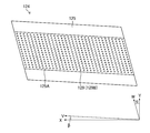
- FIG. 8 is an enlarged view of the nozzle surface of the line head shown in FIG.
- the nozzle surface 125 of the head module 124 has a parallel quadrilateral shape.
- Dummy plates 127 are attached to both ends of the support frame 126.
- the nozzle surface 125 of the inkjet head 122, together with the surface 127A of the dummy plate 127, has a rectangular shape as a whole.
- a strip-shaped nozzle arrangement portion 125A is provided at the central portion of the nozzle surface 125 of the head module 124.
- the nozzle arrangement portion 125A functions as a substantial nozzle surface 125.
- the nozzle is provided in the nozzle arrangement portion 125A.
- the nozzles are not shown individually, but the nozzle row 129A composed of a plurality of nozzles is shown.
- FIG. 9 is a plan view showing an example of nozzle arrangement of the line head shown in FIG. 7.
- a two-dimensional arrangement is applied to the nozzle surface 125 of the head module 124, and a plurality of nozzle openings 129B are arranged.
- the head module 124 has an end face on the long side along the V direction having an inclination of an angle ⁇ with respect to the paper width direction and a short side along the W direction having an inclination of an angle ⁇ with respect to the paper transport direction. It has a plane shape of a parallelogram having an end face.
- a plurality of nozzle openings 129B are arranged in a matrix in the row direction along the V direction and the column direction along the W direction.
- the nozzle openings 129B may be arranged along a row direction along the paper width direction and a column direction diagonally intersecting the paper width direction.
- each nozzle 129 projected along the nozzle row direction in the matrix arrangement has a density that achieves the maximum recording resolution in the nozzle row direction.
- the projection nozzle row is a nozzle row in which each nozzle 129 in the two-dimensional nozzle arrangement is projected normally along the nozzle row direction.
- Approximately equal intervals mean that the printing apparatus 100 has substantially equal intervals as recordable drip points.
- the concept of equal spacing also includes those that are slightly spaced apart in consideration of at least one of the manufacturing error and the movement of the droplets on the substrate due to landing interference.
- the projected nozzle array corresponds to a substantial nozzle array. Considering the projection nozzle array, it is possible to associate each nozzle with a nozzle number indicating the nozzle position in the order in which the projection nozzles are arranged along the nozzle array direction. In FIG. 9, the projection nozzle row is not shown.
- the projection nozzle sequence is illustrated with reference numeral 129B in FIG.
- the arrangement form of the nozzle 129 of the inkjet head 122 is not limited, and various arrangement forms of the nozzle 129 can be adopted.
- a straight line arrangement, a V-shaped nozzle arrangement, and a polygonal line-shaped nozzle arrangement such as a W-shape in which the V-shaped arrangement is a repeating unit are also available. It is possible.
- the nozzle 129 includes the nozzle opening 129B shown in FIG.
- the above-mentioned arrangement of the nozzles 129 may be read as the arrangement of the nozzle openings 129B. The same applies to the following description.
- the nozzle 129 includes a flow path that communicates with each of the plurality of nozzle openings 129B and the plurality of nozzle openings 129B.
- the inkjet head 122 includes a pressurizing element corresponding to each of the plurality of nozzles 129. Piezoelectric elements and heating elements can be applied as the pressurizing element. The flow path, the piezoelectric element, and the heating element are not shown.
- the inkjet head 122 can apply a piezojet method including a piezoelectric element as a pressurizing element.
- the inkjet head 122 may apply a thermal method including a heating element as a pressurizing element. The same applies to the serial head described below.
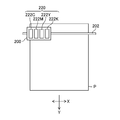
- FIG. 10 is a configuration diagram showing a configuration example of a printing unit to which the serial head is applied.
- a serial head in which a plurality of nozzles are arranged along the paper transport direction is applied to the inkjet head 222C, the inkjet head 222M, the inkjet head 222Y, and the inkjet head 222K shown in FIG.
- the illustration of the plurality of nozzles is omitted.
- the plurality of nozzles are designated by reference numeral 229 and are shown in FIG.
- the Inkjet Head 222C, Inkjet Head 222M, Inkjet Head 222Y, and Inkjet Head 222K are mounted on a carriage 200 that reciprocates along the paper width direction.
- the carriage 200 is supported so as to be reciprocally movable along the paper width direction by using the guide 202.
- the printing unit 220 including the serial head scans the carriage one or more times to print one pass having a certain length in the paper transport direction, and transports the paper according to the printing of one pass to carry a plurality of passes. Is printed, and one image is printed.
- FIG. 11 is an enlarged view of the nozzle surface of the serial head shown in FIG.
- the inkjet head 222C, the inkjet head 222M, the inkjet head 222Y, and the inkjet head 222K are collectively referred to as the inkjet head 222.
- a plurality of nozzle openings 229B are arranged along the longitudinal direction.
- FIG. 11 illustrates an embodiment in which a plurality of nozzle openings 229B can be arranged in a row, a plurality of nozzle openings 229B may be arranged in two rows in a zigzag manner.
- Reference numeral 230 in FIG. 11 represents a pressure chamber communicating with the nozzle opening 229B.
- the nozzle opening 229B communicates with the pressure chamber 230 via a flow path.
- the inkjet head 222 pressurizes the ink contained in the pressure chamber 230 and ejects ink droplets from the nozzle opening.
- Reference numeral 229 indicates a nozzle.
- a streak defect can be mentioned as an example of a defect in printed matter.
- the streak defect may occur along a direction orthogonal to the direction in which the plurality of nozzles are arranged due to the ejection abnormality of the nozzles. Visible streak defects reduce the quality of the printed matter.
- a streak defect occurs due to the nozzle in which the ejection abnormality has occurred. The streak defects for each printing method will be described below.
- FIG. 12 is an explanatory diagram of streak defects in a printed matter generated by using a printing unit to which a line head is applied.
- Reference numeral 129C indicates a projection nozzle array in which the matrix-arranged nozzles 129 shown in FIG. 9 are projected in the paper width direction.
- the projection nozzle row 129C shown in FIG. 12 is a substantial nozzle arrangement of the matrix-arranged nozzles 129 shown in FIG.
- Nozzle 129D is a non-ejection nozzle.
- the printed matter 240 in which the image is printed on the paper P has a streak defect 242 at the printing position of the nozzle 129D.
- the illustration of the image of the printed matter 240 is omitted.
- streak defects 242 that are parallel to the paper transport direction and have a length corresponding to the printing range of the nozzle 129D in the paper transport direction may occur.
- the paper transport direction when the line head is provided corresponds to an example of the relative transport direction between the printing unit and the medium.
- FIG. 13 is an explanatory diagram of streak defects in a printed matter generated by using a printing unit to which a serial head is applied.
- the plurality of nozzles 229 shown in FIG. 13 correspond to the plurality of nozzle openings 229B shown in FIG.
- Reference numeral 229A indicates a nozzle array having a plurality of nozzles 229 as constituent elements.
- Nozzle 229D is a non-ejection nozzle.
- the printed matter 250 on which the image is printed on the paper P has a streak defect 252 at the printing position of the nozzle 229D.
- the illustration of the image of the printed matter 250 is omitted.
- the streak defect 252 is parallel to the scanning direction of the carriage 200 shown in FIG. 10, and has a length corresponding to the printing range of the nozzle 129D in the scanning direction of the carriage 200.
- the scanning direction of the carriage 200 when the serial head is provided corresponds to an example of the relative transport direction between the printing unit and the medium.
- FIG. 14 is an explanatory diagram of the deep learning model.
- learning is performed using the disturbance imparting learning data set 262 to which the disturbance is added.
- the defect to be inspected is a streak defect generated in the printed matter, and the disturbance is a misalignment of the imaged data with respect to the print data in the direction orthogonal to the streak defect.
- a matching method is applied to find the position where the error is minimized when the pixels are shifted within the search range.
- the accuracy of the alignment process and the period of the alignment process tend to be in a trade-off relationship.
- the period of the alignment process is limited according to the limitation of the inspection period, and it may be difficult to maintain the alignment accuracy.
- the alignment processing period is not limited, perfect alignment is difficult and slight misalignment may occur.
- the training data that has undergone the ideal alignment processing is used for training, robustness against the error of the alignment processing cannot be obtained, and an image structure similar to a streak defect such as a barcode or a grid is obtained. Misalignment in the pattern to be held is easily detected as a streak defect.
- the imaging data in which the position is intentionally shifted with respect to the print data in the direction orthogonal to the direction of the streak defect is applied to the learning data to prevent the misalignment. Has gained robustness.
- the normal learning data set 260 and the disturbance imparting learning data set 262 are input.
- Defect correct answer data 264 is input to the deep learning model 20.
- the defect correct answer data 264 is included in the normal learning data set 260 and the disturbance imparting learning data set 262.
- the normal learning data set 260 and the disturbance imparting learning data set 262 are input, and the defect information of each is output.
- the error calculation unit 35 compares the defect information output from the output layer 34 with the defect correct answer data 264, and outputs the error information.
- the error information is transmitted to the parameter update unit 37.
- the parameter update unit 37 updates the parameters applied to the intermediate layer 32 based on the error information.
- the deep learning model 20 performs learning until a predetermined accuracy is achieved.
- the normal learning data set 260 includes print data and imaging data.
- the normal training data set 260 corresponds to the ideally aligned training data described above.
- the disturbance imparting learning data set 262 includes print data and disturbance imparting imaging data.
- the disturbance imparted imaging data is imaging data whose position is shifted in a direction orthogonal to the direction of the streak defect with respect to the print data. As the print data of the disturbance imparting learning data set 262, the print data of the normal learning data set 260 can be applied.
- the disturbance imparted imaging data is generated by shifting the position of one pixel to three pixels when a maximum deviation of three pixels occurs in the alignment process between the print data and the imaging data. That is, the disturbance imparted imaging data is generated by shifting the position of the imaging data with respect to the print data step by step within the range of the alignment accuracy between the print data and the imaging data.
- the acquisition of the disturbance imparting learning data set 262 shown in the present embodiment may include the generation of the disturbance imparting learning data set 262 that generates the disturbance imparting imaging data from the imaging data.
- the deep learning model 20 performs learning by applying the disturbance imparting learning data set 262 to obtain robustness against a positional deviation between the print data and the imaging data. As a result, it is possible to avoid erroneous detection of streak defects due to misalignment between the print data and the imaging data. In addition, the accuracy of detecting streak defects can be reduced to speed up the inspection of printed matter.
- the normal learning data set 260 and the disturbance imparting learning data set 262 include print data. Defect information of printed matter occurs in the imaged data but not in the printed data. When learning to extract a defect structure is performed, if only the imaging data is used, a pattern structure similar to the defect structure may be recognized as a defect structure. Therefore, by including the print data in the normal learning data set 260 and the disturbance imparting learning data set 262, the performance of the deep learning model 20 can be improved.
- the deep learning model 20 described in the embodiment corresponds to an example of a learning model in which the relationship between the defect candidate detected from the imaging data and the defect in the printed matter is learned.
- FIG. 15 is a flowchart showing a procedure of a learning method applied to the deep learning model shown in FIG.
- the input layer 30 acquires the normal learning data set 260.
- the process proceeds to the disturbance imparting learning data set acquisition step S102.
- the input layer 30 acquires the disturbance imparting learning data set 262. After the disturbance imparting learning data set acquisition step S102, the process proceeds to the defect correct answer data acquisition step S104.
- the disturbance imparting learning data set acquisition step S102 may be performed before the execution of the normal learning data set acquisition step S100.
- the disturbance imparting learning data set acquisition step S102 may be performed in parallel with the normal learning data set acquisition step S100.
- the deep learning model 20 acquires the defect correct answer data 264.
- the learning step S106 is performed after the defect correct answer data acquisition step S104.
- the defect correct answer data acquisition step S104 may be performed before at least one of the normal learning data set acquisition step S100 and the disturbance imparting learning data set acquisition step S102.
- the defect correct answer data acquisition step S104 may be performed in parallel with at least one of the normal learning data set acquisition step S100 and the disturbance imparting learning data set acquisition step S102.
- the deep learning model 20 performs learning using the normal learning data set 260 and the disturbance imparting learning data set 262.
- the learning step S106 includes a defect information output step of outputting defect information, an error calculation step of comparing the defect information with the defect correct answer data 264, and a parameter update step of updating the parameters applied to the intermediate layer 32 based on the comparison result. Is done.
- the process proceeds to the deep learning model updating step S108.
- the deep learning model 20 is updated. After the deep learning model update step S108, the learning method is terminated.
- the learning using the normal learning data set 260 and the disturbance imparting learning data set 262 in combination is illustrated, but even when the learning using only the disturbance imparting learning data set 262 is performed, the print data and the imaging data are combined. It is possible to obtain a certain robustness against misalignment.
- the direction in which the position of the imaging data is shifted with respect to the print data may be a direction that diagonally intersects the direction of the streak defect, and the imaging data may be non-rotating with respect to the print data.
- the direction that intersects the direction of the streak defect may be the direction that intersects the relative transport direction between the printing portion and the paper P.
- the direction orthogonal to the direction of the streak defect can be a substantial nozzle arrangement direction in the printing portion.
- the relative transport direction between the printing unit and the paper P and the substantially nozzle arrangement direction can be set according to the printing method of the printing unit.
- a printed matter is printed using a trained deep learning model that has been trained by inputting a disturbance-imparted learning data set 262 including disturbance-imparted imaging data whose position is shifted with respect to the print data and outputting defect information of streak defects. Inspect for streak defects. This makes it possible to obtain robustness against misalignment of the imaged data with respect to the printed data in the printed matter inspection.
- the disturbance imparting learning data set 262 includes disturbance imparted imaging data whose position is shifted with respect to the print data within the range of alignment accuracy between the print data and the imaging data.
- the deep learning model 20 inputs a normal learning data set 260 including imaging data that is ideally aligned with respect to the print data. Thereby, the accuracy of the deep learning model 20 can be improved.
- the normal learning data set 260 and the disturbance imparting learning data set 262 include print data. As a result, learning for extracting the difference between the imaged data and the print data can be performed, and the performance of the deep learning model 20 can be improved.
- the misalignment of the imaging data with respect to the print data is in a direction orthogonal to the relative transport direction between the printing unit and the paper. As a result, it is possible to obtain robustness against misalignment of the imaging data in the detection of streak defects along the relative transport direction between the printing unit and the paper.
- FIG. 16 is an explanatory diagram of a deep learning model according to an application example.
- learning using the first disturbance imparting learning set 262A and the second disturbance imparting learning set 262B in combination is carried out.
- the image structure of the imaged data may change with respect to the print data, such as a change in the dot pattern caused by the correction of the printing device.
- a change in the image structure of the imaging data with respect to the printing data may occur as a disturbance between the printing data and the imaging data. It is possible to obtain robustness against such a disturbance by performing learning using the imaging data in which a change in the image structure of the imaging data with respect to the print data is given as a disturbance.
- the first disturbance imparting learning set 262A shown in FIG. 16 corresponds to the disturbance imparting learning data set 262 shown in FIG.
- the second disturbance addition learning set 262B is applied to the imaged data with the change in the image structure of the imaged data with respect to the print data as a disturbance.
- the change in the image structure of the imaged data with respect to the print data may be due to the change in the image structure of the printed matter with respect to the print data.
- Examples of such cases include correction processing of the printing unit, excessive or insufficient amount of ink of a specific color with respect to a specified amount, uneven density, noise generated due to the mesh type and the surrounding environment of the printing apparatus, and the like.
- Examples of the correction processing of the printing unit include ejection failure correction processing, nozzle ejection characteristic correction processing such as unevenness correction, and color correction processing.
- An example of an excess or too small amount of ink for a specific color with respect to a specified amount is ink loss such as yellow.
- Examples of density unevenness include transport unevenness of paper P and speed unevenness of carriage 200.
- Examples of net types include AM screens, FM screens, hybrid screens and the like.
- AM is an abbreviation for Amplitude Modulation.
- FM is an abbreviation for Frequency Modulation.
- the net is sometimes called a halftone or the like.
- noise caused by the ambient environment of the printing device examples include noise caused by the ambient temperature of the printing device and noise caused by the ambient humidity of the printing device.
- the image structure of the imaged data obtained by imaging the printed matter subjected to the ejection failure correction process is inconspicuous visually, but the image structure is changed with respect to the printed data.
- such a change in the image structure may be erroneously detected as a defective structure. Therefore, it is possible to learn the change in the image structure of the imaged data with respect to the print data due to the ejection failure correction process as a disturbance and avoid such false detection.
- the change in the image structure of the imaged data with respect to the print data caused by the correction of the nozzle ejection characteristics such as unevenness correction and the correction processing of the printing unit such as color correction can be learned as a disturbance, and such false detection can be avoided.
- the omission of yellow ink can be clearly confirmed in the blue channel of the imaged data, but it may not be visible in the printed matter.
- a printed matter having a defect structure that cannot be visually recognized and a defect structure that is difficult to see may be determined to have no defect structure. Therefore, it is possible to learn as a disturbance the change in the image structure of the imaged data with respect to the print data due to the amount of ink being too small with respect to the specified amount such as ink loss, and avoid such false detection.
- An excess of the specified amount of ink can be dealt with in the same manner as an excess of the specified amount of ink.
- the change in the image structure of the imaging data with respect to the printing data may be due to the characteristics of the imaging device.
- An example of such a case is an individual difference of an image pickup device provided in the image pickup apparatus.
- An example of individual differences in the image sensor is a local change in the resolving power of the image pickup data due to the MTF characteristics and the CTF characteristics of the image pickup device.
- MTF is an abbreviation for Modulation Transfer Function.
- CTF is an abbreviation for Contrast Transfer Function.
- shading occurs in which the edges of the captured data become dark, and the brightness of the edges and non-ends of the captured data when the printed matter is imaged using illumination of uniform brightness. Differences can be mentioned.
- the change in the image structure of the captured data with respect to the printed data may be caused by the paper P applied to the printed matter.
- Examples of such cases include a change in the brightness of the imaging data depending on the type of the paper P, a stain on the paper P, and the like.
- Changes in the image structure of the imaging data with respect to the print data caused by the imaging device and changes in the image structure of the imaging data with respect to the print data caused by the paper P can also be learned as disturbances and erroneous detection can be avoided.
- the second disturbance imparted imaging data set shown in FIG. 16 may be a combination of a plurality of disturbances.
- at least one of the disturbance caused by the change in the image structure of the printed matter with respect to the print data, the disturbance caused by the characteristics of the image sensor, and the disturbance caused by the paper P may be combined.
- a plurality of disturbances may be combined among the disturbances caused by the change in the image structure of the printed matter with respect to the print data.
- the second disturbance imparting learning set 262B including the second disturbance imparting imaging data in which the disturbance caused by the change in the image structure of the imaging data with respect to the print data is imparted is the imaging data for the print data.
- the deep learning model 20A is trained in combination with the first disturbance imparting learning set 262A to which the disturbance caused by the misalignment of is applied. As a result, the deep learning model 20A can obtain robustness against various disturbances.
- the printed matter inspection device 10 provided in the printing device 100 may apply an imaging device that irradiates illumination light from the printed surface of the printed matter and receives the reflected light of the illumination light, or may apply an imaging device that receives the reflected light of the illumination light, or the back surface of the printed surface of the printed matter.
- An image pickup device that irradiates the illumination light from the light source and receives the transmitted light of the illumination light may be applied.
- a program corresponding to the printed matter inspection apparatus and the printed matter inspection method disclosed in the present specification may be configured. That is, it is possible to configure a program that allows the computer to realize the functions of each part shown in FIG. 1 and the functions of each part shown in FIG.
- the imaging data acquisition function corresponding to the imaging data acquisition unit 12 shown in FIG. 1, the print data acquisition function corresponding to the print data acquisition unit 14, the alignment processing function corresponding to the alignment processing unit 15, and the inspection processing unit 16 A program that realizes the corresponding inspection processing function and the output function corresponding to the output unit 18 in the computer can be configured.
- the constituent requirements can be appropriately changed, added, or deleted without departing from the gist of the present invention.
- the present invention is not limited to the embodiments described above, and many modifications can be made by a person having ordinary knowledge in the art within the technical idea of the present invention.
Landscapes
- Engineering & Computer Science (AREA)
- Theoretical Computer Science (AREA)
- Physics & Mathematics (AREA)
- General Physics & Mathematics (AREA)
- Computer Vision & Pattern Recognition (AREA)
- Evolutionary Computation (AREA)
- Quality & Reliability (AREA)
- Multimedia (AREA)
- Health & Medical Sciences (AREA)
- General Health & Medical Sciences (AREA)
- Software Systems (AREA)
- Databases & Information Systems (AREA)
- Computing Systems (AREA)
- Medical Informatics (AREA)
- Artificial Intelligence (AREA)
- Analytical Chemistry (AREA)
- Textile Engineering (AREA)
- Life Sciences & Earth Sciences (AREA)
- Chemical & Material Sciences (AREA)
- General Engineering & Computer Science (AREA)
- Biochemistry (AREA)
- Immunology (AREA)
- Pathology (AREA)
- Image Processing (AREA)
- Investigating Materials By The Use Of Optical Means Adapted For Particular Applications (AREA)
- Ink Jet (AREA)
- Accessory Devices And Overall Control Thereof (AREA)
- Image Analysis (AREA)
Priority Applications (3)
| Application Number | Priority Date | Filing Date | Title |
|---|---|---|---|
| EP20865804.7A EP4032706B1 (en) | 2019-09-18 | 2020-09-08 | Printed matter inspecting device, printed matter inspecting method, program, and printing apparatus |
| JP2021546625A JP7273169B2 (ja) | 2019-09-18 | 2020-09-08 | 印刷物検査装置、印刷物検査方法、プログラム及び印刷装置 |
| US17/691,505 US12182989B2 (en) | 2019-09-18 | 2022-03-10 | Printed matter inspection device, printed matter inspection method, program, and printing apparatus |
Applications Claiming Priority (2)
| Application Number | Priority Date | Filing Date | Title |
|---|---|---|---|
| JP2019169310 | 2019-09-18 | ||
| JP2019-169310 | 2019-09-18 |
Related Child Applications (1)
| Application Number | Title | Priority Date | Filing Date |
|---|---|---|---|
| US17/691,505 Continuation US12182989B2 (en) | 2019-09-18 | 2022-03-10 | Printed matter inspection device, printed matter inspection method, program, and printing apparatus |
Publications (1)
| Publication Number | Publication Date |
|---|---|
| WO2021054200A1 true WO2021054200A1 (ja) | 2021-03-25 |
Family
ID=74883131
Family Applications (1)
| Application Number | Title | Priority Date | Filing Date |
|---|---|---|---|
| PCT/JP2020/033968 Ceased WO2021054200A1 (ja) | 2019-09-18 | 2020-09-08 | 印刷物検査装置、印刷物検査方法、プログラム及び印刷装置 |
Country Status (4)
| Country | Link |
|---|---|
| US (1) | US12182989B2 (https=) |
| EP (1) | EP4032706B1 (https=) |
| JP (1) | JP7273169B2 (https=) |
| WO (1) | WO2021054200A1 (https=) |
Cited By (2)
| Publication number | Priority date | Publication date | Assignee | Title |
|---|---|---|---|---|
| CN116363050A (zh) * | 2021-12-28 | 2023-06-30 | 细美事有限公司 | 喷嘴检查单元及包括其的基板处理装置 |
| US12555223B2 (en) | 2022-11-10 | 2026-02-17 | Fujifilm Corporation | Printed material inspection device, printed material inspection method, program, and printing system |
Families Citing this family (4)
| Publication number | Priority date | Publication date | Assignee | Title |
|---|---|---|---|---|
| JP7482662B2 (ja) * | 2020-03-25 | 2024-05-14 | 東京エレクトロン株式会社 | 異常検出装置及び異常検出方法 |
| JP2022049858A (ja) * | 2020-09-17 | 2022-03-30 | セイコーエプソン株式会社 | 機械学習方法、機械学習プログラム、および液体吐出システム |
| US20240255916A1 (en) * | 2023-01-26 | 2024-08-01 | Nano Dimension Technologies Ltd | Nozzle monitoring and management in 2d and/or 3d inkjet printing systems |
| CN120912601B (zh) * | 2025-10-09 | 2026-01-23 | 泉州湖南大学工业设计与机器智能创新研究院 | 一种印刷产品缺陷检测方法、装置及可读介质 |
Citations (6)
| Publication number | Priority date | Publication date | Assignee | Title |
|---|---|---|---|---|
| JPH0721367A (ja) | 1993-06-22 | 1995-01-24 | Oyo Keisoku Kenkyusho:Kk | 画像認識装置 |
| JPH07126604A (ja) | 1993-10-28 | 1995-05-16 | Nisshin Oil Mills Ltd:The | 有機液体のゲル化又は固化剤 |
| JPH1063789A (ja) * | 1996-08-27 | 1998-03-06 | Nippon Telegr & Teleph Corp <Ntt> | 識別関数学習方法 |
| JP2014066618A (ja) * | 2012-09-26 | 2014-04-17 | Dainippon Screen Mfg Co Ltd | 画像検査装置及び画像検査方法並びに画像検査プログラム |
| JP2019101540A (ja) * | 2017-11-29 | 2019-06-24 | 大日本印刷株式会社 | 設備診断装置、設備診断方法、プログラム |
| US20190236738A1 (en) * | 2018-02-01 | 2019-08-01 | Fst21 Ltd | System and method for detection of identity fraud |
Family Cites Families (9)
| Publication number | Priority date | Publication date | Assignee | Title |
|---|---|---|---|---|
| US20060203028A1 (en) | 2005-03-10 | 2006-09-14 | Manish Agarwal | Apparatus and method for print quality control |
| JP5025327B2 (ja) * | 2007-05-15 | 2012-09-12 | キヤノン株式会社 | インクジェット記録装置および記録方法 |
| JP2009303185A (ja) * | 2008-06-17 | 2009-12-24 | Canon Inc | 画像処理装置およびその方法 |
| US8132885B2 (en) * | 2009-03-10 | 2012-03-13 | Xerox Corporation | System and method for evaluating and correcting image quality in an image generating device |
| JP5599239B2 (ja) * | 2010-06-28 | 2014-10-01 | 富士フイルム株式会社 | インクジェット印刷装置及びその印刷方法 |
| US8531743B2 (en) * | 2010-10-18 | 2013-09-10 | Xerox Corporation | System and method for detecting missing inkjets in an inkjet printer using image data of printed documents without a priori knowledge of the documents |
| JP5283685B2 (ja) * | 2010-12-17 | 2013-09-04 | 富士フイルム株式会社 | 不良記録素子の検出装置及び方法、並びに画像形成装置及び方法 |
| JP6571575B2 (ja) | 2016-03-28 | 2019-09-04 | 富士フイルム株式会社 | スジ検出方法及び装置、印刷装置並びにプログラム |
| WO2019142517A1 (ja) | 2018-01-17 | 2019-07-25 | 富士フイルム株式会社 | 印刷装置、画像欠陥検出装置、方法及びプログラム |
-
2020
- 2020-09-08 JP JP2021546625A patent/JP7273169B2/ja active Active
- 2020-09-08 EP EP20865804.7A patent/EP4032706B1/en active Active
- 2020-09-08 WO PCT/JP2020/033968 patent/WO2021054200A1/ja not_active Ceased
-
2022
- 2022-03-10 US US17/691,505 patent/US12182989B2/en active Active
Patent Citations (6)
| Publication number | Priority date | Publication date | Assignee | Title |
|---|---|---|---|---|
| JPH0721367A (ja) | 1993-06-22 | 1995-01-24 | Oyo Keisoku Kenkyusho:Kk | 画像認識装置 |
| JPH07126604A (ja) | 1993-10-28 | 1995-05-16 | Nisshin Oil Mills Ltd:The | 有機液体のゲル化又は固化剤 |
| JPH1063789A (ja) * | 1996-08-27 | 1998-03-06 | Nippon Telegr & Teleph Corp <Ntt> | 識別関数学習方法 |
| JP2014066618A (ja) * | 2012-09-26 | 2014-04-17 | Dainippon Screen Mfg Co Ltd | 画像検査装置及び画像検査方法並びに画像検査プログラム |
| JP2019101540A (ja) * | 2017-11-29 | 2019-06-24 | 大日本印刷株式会社 | 設備診断装置、設備診断方法、プログラム |
| US20190236738A1 (en) * | 2018-02-01 | 2019-08-01 | Fst21 Ltd | System and method for detection of identity fraud |
Non-Patent Citations (1)
| Title |
|---|
| See also references of EP4032706A4 |
Cited By (4)
| Publication number | Priority date | Publication date | Assignee | Title |
|---|---|---|---|---|
| CN116363050A (zh) * | 2021-12-28 | 2023-06-30 | 细美事有限公司 | 喷嘴检查单元及包括其的基板处理装置 |
| JP2023098640A (ja) * | 2021-12-28 | 2023-07-10 | セメス株式会社 | ノズル検査ユニットおよびそれを含む基板処理装置 |
| JP7372432B2 (ja) | 2021-12-28 | 2023-10-31 | セメス株式会社 | ノズル検査ユニットおよびそれを含む基板処理装置 |
| US12555223B2 (en) | 2022-11-10 | 2026-02-17 | Fujifilm Corporation | Printed material inspection device, printed material inspection method, program, and printing system |
Also Published As
| Publication number | Publication date |
|---|---|
| JPWO2021054200A1 (https=) | 2021-03-25 |
| EP4032706B1 (en) | 2024-11-27 |
| JP7273169B2 (ja) | 2023-05-12 |
| EP4032706A1 (en) | 2022-07-27 |
| US20220198638A1 (en) | 2022-06-23 |
| EP4032706A4 (en) | 2022-10-19 |
| US12182989B2 (en) | 2024-12-31 |
Similar Documents
| Publication | Publication Date | Title |
|---|---|---|
| JP7273169B2 (ja) | 印刷物検査装置、印刷物検査方法、プログラム及び印刷装置 | |
| JP7110349B2 (ja) | 機械学習モデルの生成装置、方法、プログラム、検査装置及び検査方法、並びに印刷装置 | |
| US10105948B2 (en) | Image inspection device, image inspection method, program, and ink jet printing system | |
| JP6694362B2 (ja) | 画像検査方法及び装置、プログラム並びに画像記録システム | |
| JP6571575B2 (ja) | スジ検出方法及び装置、印刷装置並びにプログラム | |
| JP5283685B2 (ja) | 不良記録素子の検出装置及び方法、並びに画像形成装置及び方法 | |
| JP6472058B2 (ja) | 画像形成装置及び画像補正方法 | |
| JP5681476B2 (ja) | 不良記録素子の検出装置及び方法、並びに画像形成装置及び方法 | |
| JP2017094523A (ja) | インクジェット印刷装置及びインクジェットヘッド吐出性能評価方法 | |
| US12304220B2 (en) | Defect inspection device, defect inspection method, and program, and printing device and method of manufacturing printed matter | |
| WO2019188911A1 (ja) | 画像形成装置及び方法、異常ノズル検出方法並びに印刷物の製造方法 | |
| WO2020179742A1 (ja) | 検査方法、プログラム、検査装置、及び印刷装置 | |
| WO2019142517A1 (ja) | 印刷装置、画像欠陥検出装置、方法及びプログラム | |
| JP5303503B2 (ja) | 画像検査装置および印刷装置、並びに、画像検査方法 | |
| JP6814883B2 (ja) | 画像形成装置及び画像形成方法 | |
| JP2016074187A (ja) | テスト画像、テスト画像形成システム、テスト画像形成方法、テスト画像形成プログラム、記憶媒体、記憶媒体、異常記録素子検出システム、異常記録素子検出方法、異常記録素子検出プログラム、及び記憶媒体 | |
| JP7225068B2 (ja) | 印刷物の欠陥検査装置、欠陥検査方法及びプログラム、並びに印刷システム | |
| JP7126477B2 (ja) | 画像検査方法及び装置、プログラム並びに画像記録システム | |
| JP2021128064A (ja) | 印刷物の欠陥検査装置、欠陥検査方法及びプログラム、並びに印刷システム | |
| US12555223B2 (en) | Printed material inspection device, printed material inspection method, program, and printing system | |
| WO2025154463A1 (ja) | 印刷物の欠陥検査装置、欠陥検査方法及びプログラム、印刷システム | |
| JP6463455B2 (ja) | テスト画像、テスト画像形成システム、テスト画像形成方法、テスト画像形成プログラム、記憶媒体、記憶媒体、異常記録素子検出システム、異常記録素子検出方法、異常記録素子検出プログラム、及び記憶媒体 | |
| JP2020144795A (ja) | 画像形成装置、及び、画像形成装置の検査方法 | |
| JPWO2018207535A1 (ja) | 解像力測定方法及び装置、プログラム並びに印刷装置 |
Legal Events
| Date | Code | Title | Description |
|---|---|---|---|
| 121 | Ep: the epo has been informed by wipo that ep was designated in this application |
Ref document number: 20865804 Country of ref document: EP Kind code of ref document: A1 |
|
| ENP | Entry into the national phase |
Ref document number: 2021546625 Country of ref document: JP Kind code of ref document: A |
|
| NENP | Non-entry into the national phase |
Ref country code: DE |
|
| ENP | Entry into the national phase |
Ref document number: 2020865804 Country of ref document: EP Effective date: 20220419 |