WO2021054200A1 - Printed matter inspecting device, printed matter inspecting method, program, and printing apparatus - Google Patents
Printed matter inspecting device, printed matter inspecting method, program, and printing apparatus Download PDFInfo
- Publication number
- WO2021054200A1 WO2021054200A1 PCT/JP2020/033968 JP2020033968W WO2021054200A1 WO 2021054200 A1 WO2021054200 A1 WO 2021054200A1 JP 2020033968 W JP2020033968 W JP 2020033968W WO 2021054200 A1 WO2021054200 A1 WO 2021054200A1
- Authority
- WO
- WIPO (PCT)
- Prior art keywords
- data
- imaging data
- disturbance
- printed matter
- learning
- Prior art date
Links
Images


Classifications
-
- G—PHYSICS
- G06—COMPUTING; CALCULATING OR COUNTING
- G06V—IMAGE OR VIDEO RECOGNITION OR UNDERSTANDING
- G06V10/00—Arrangements for image or video recognition or understanding
- G06V10/70—Arrangements for image or video recognition or understanding using pattern recognition or machine learning
- G06V10/82—Arrangements for image or video recognition or understanding using pattern recognition or machine learning using neural networks
-
- G—PHYSICS
- G06—COMPUTING; CALCULATING OR COUNTING
- G06T—IMAGE DATA PROCESSING OR GENERATION, IN GENERAL
- G06T7/00—Image analysis
- G06T7/0002—Inspection of images, e.g. flaw detection
- G06T7/0004—Industrial image inspection
- G06T7/001—Industrial image inspection using an image reference approach
-
- B—PERFORMING OPERATIONS; TRANSPORTING
- B41—PRINTING; LINING MACHINES; TYPEWRITERS; STAMPS
- B41J—TYPEWRITERS; SELECTIVE PRINTING MECHANISMS, i.e. MECHANISMS PRINTING OTHERWISE THAN FROM A FORME; CORRECTION OF TYPOGRAPHICAL ERRORS
- B41J2/00—Typewriters or selective printing mechanisms characterised by the printing or marking process for which they are designed
- B41J2/005—Typewriters or selective printing mechanisms characterised by the printing or marking process for which they are designed characterised by bringing liquid or particles selectively into contact with a printing material
- B41J2/01—Ink jet
- B41J2/015—Ink jet characterised by the jet generation process
-
- B—PERFORMING OPERATIONS; TRANSPORTING
- B41—PRINTING; LINING MACHINES; TYPEWRITERS; STAMPS
- B41J—TYPEWRITERS; SELECTIVE PRINTING MECHANISMS, i.e. MECHANISMS PRINTING OTHERWISE THAN FROM A FORME; CORRECTION OF TYPOGRAPHICAL ERRORS
- B41J2/00—Typewriters or selective printing mechanisms characterised by the printing or marking process for which they are designed
- B41J2/005—Typewriters or selective printing mechanisms characterised by the printing or marking process for which they are designed characterised by bringing liquid or particles selectively into contact with a printing material
- B41J2/01—Ink jet
- B41J2/135—Nozzles
- B41J2/145—Arrangement thereof
-
- B—PERFORMING OPERATIONS; TRANSPORTING
- B41—PRINTING; LINING MACHINES; TYPEWRITERS; STAMPS
- B41J—TYPEWRITERS; SELECTIVE PRINTING MECHANISMS, i.e. MECHANISMS PRINTING OTHERWISE THAN FROM A FORME; CORRECTION OF TYPOGRAPHICAL ERRORS
- B41J2/00—Typewriters or selective printing mechanisms characterised by the printing or marking process for which they are designed
- B41J2/005—Typewriters or selective printing mechanisms characterised by the printing or marking process for which they are designed characterised by bringing liquid or particles selectively into contact with a printing material
- B41J2/01—Ink jet
- B41J2/21—Ink jet for multi-colour printing
- B41J2/2132—Print quality control characterised by dot disposition, e.g. for reducing white stripes or banding
- B41J2/2142—Detection of malfunctioning nozzles
-
- B—PERFORMING OPERATIONS; TRANSPORTING
- B41—PRINTING; LINING MACHINES; TYPEWRITERS; STAMPS
- B41J—TYPEWRITERS; SELECTIVE PRINTING MECHANISMS, i.e. MECHANISMS PRINTING OTHERWISE THAN FROM A FORME; CORRECTION OF TYPOGRAPHICAL ERRORS
- B41J2/00—Typewriters or selective printing mechanisms characterised by the printing or marking process for which they are designed
- B41J2/005—Typewriters or selective printing mechanisms characterised by the printing or marking process for which they are designed characterised by bringing liquid or particles selectively into contact with a printing material
- B41J2/01—Ink jet
- B41J2/21—Ink jet for multi-colour printing
- B41J2/2132—Print quality control characterised by dot disposition, e.g. for reducing white stripes or banding
- B41J2/2146—Print quality control characterised by dot disposition, e.g. for reducing white stripes or banding for line print heads
-
- B—PERFORMING OPERATIONS; TRANSPORTING
- B41—PRINTING; LINING MACHINES; TYPEWRITERS; STAMPS
- B41J—TYPEWRITERS; SELECTIVE PRINTING MECHANISMS, i.e. MECHANISMS PRINTING OTHERWISE THAN FROM A FORME; CORRECTION OF TYPOGRAPHICAL ERRORS
- B41J29/00—Details of, or accessories for, typewriters or selective printing mechanisms not otherwise provided for
- B41J29/38—Drives, motors, controls or automatic cut-off devices for the entire printing mechanism
- B41J29/393—Devices for controlling or analysing the entire machine ; Controlling or analysing mechanical parameters involving printing of test patterns
-
- G—PHYSICS
- G01—MEASURING; TESTING
- G01N—INVESTIGATING OR ANALYSING MATERIALS BY DETERMINING THEIR CHEMICAL OR PHYSICAL PROPERTIES
- G01N21/00—Investigating or analysing materials by the use of optical means, i.e. using sub-millimetre waves, infrared, visible or ultraviolet light
- G01N21/84—Systems specially adapted for particular applications
- G01N21/88—Investigating the presence of flaws or contamination
- G01N21/89—Investigating the presence of flaws or contamination in moving material, e.g. running paper or textiles
- G01N21/892—Investigating the presence of flaws or contamination in moving material, e.g. running paper or textiles characterised by the flaw, defect or object feature examined
-
- G—PHYSICS
- G06—COMPUTING; CALCULATING OR COUNTING
- G06K—GRAPHICAL DATA READING; PRESENTATION OF DATA; RECORD CARRIERS; HANDLING RECORD CARRIERS
- G06K15/00—Arrangements for producing a permanent visual presentation of the output data, e.g. computer output printers
- G06K15/02—Arrangements for producing a permanent visual presentation of the output data, e.g. computer output printers using printers
- G06K15/027—Test patterns and calibration
-
- G—PHYSICS
- G06—COMPUTING; CALCULATING OR COUNTING
- G06T—IMAGE DATA PROCESSING OR GENERATION, IN GENERAL
- G06T7/00—Image analysis
- G06T7/0002—Inspection of images, e.g. flaw detection
- G06T7/0004—Industrial image inspection
-
- G—PHYSICS
- G06—COMPUTING; CALCULATING OR COUNTING
- G06T—IMAGE DATA PROCESSING OR GENERATION, IN GENERAL
- G06T7/00—Image analysis
- G06T7/30—Determination of transform parameters for the alignment of images, i.e. image registration
-
- G—PHYSICS
- G06—COMPUTING; CALCULATING OR COUNTING
- G06V—IMAGE OR VIDEO RECOGNITION OR UNDERSTANDING
- G06V10/00—Arrangements for image or video recognition or understanding
- G06V10/70—Arrangements for image or video recognition or understanding using pattern recognition or machine learning
- G06V10/77—Processing image or video features in feature spaces; using data integration or data reduction, e.g. principal component analysis [PCA] or independent component analysis [ICA] or self-organising maps [SOM]; Blind source separation
- G06V10/774—Generating sets of training patterns; Bootstrap methods, e.g. bagging or boosting
- G06V10/7747—Organisation of the process, e.g. bagging or boosting
-
- G—PHYSICS
- G06—COMPUTING; CALCULATING OR COUNTING
- G06V—IMAGE OR VIDEO RECOGNITION OR UNDERSTANDING
- G06V20/00—Scenes; Scene-specific elements
- G06V20/60—Type of objects
-
- G—PHYSICS
- G06—COMPUTING; CALCULATING OR COUNTING
- G06T—IMAGE DATA PROCESSING OR GENERATION, IN GENERAL
- G06T2207/00—Indexing scheme for image analysis or image enhancement
- G06T2207/10—Image acquisition modality
- G06T2207/10004—Still image; Photographic image
- G06T2207/10008—Still image; Photographic image from scanner, fax or copier
-
- G—PHYSICS
- G06—COMPUTING; CALCULATING OR COUNTING
- G06T—IMAGE DATA PROCESSING OR GENERATION, IN GENERAL
- G06T2207/00—Indexing scheme for image analysis or image enhancement
- G06T2207/20—Special algorithmic details
- G06T2207/20081—Training; Learning
-
- G—PHYSICS
- G06—COMPUTING; CALCULATING OR COUNTING
- G06T—IMAGE DATA PROCESSING OR GENERATION, IN GENERAL
- G06T2207/00—Indexing scheme for image analysis or image enhancement
- G06T2207/20—Special algorithmic details
- G06T2207/20084—Artificial neural networks [ANN]
-
- G—PHYSICS
- G06—COMPUTING; CALCULATING OR COUNTING
- G06T—IMAGE DATA PROCESSING OR GENERATION, IN GENERAL
- G06T2207/00—Indexing scheme for image analysis or image enhancement
- G06T2207/30—Subject of image; Context of image processing
- G06T2207/30108—Industrial image inspection
- G06T2207/30144—Printing quality
Definitions
- the present invention relates to a printed matter inspection device, a printed matter inspection method, a program, and a printing device.
- Defect inspection devices that inspect defects in the inspection target by comparing the imaging data obtained by imaging the inspection target with an imaging device such as a scanner with the reference reference data are widely used.
- the defect inspection device there is a printed matter inspection device that inspects print defects caused by streaks of printed matter generated by using the printing device and ink omission.
- the printed matter inspection device compares the print data input to the printed matter with the imaged data obtained by imaging the printed printed matter, and determines the quality of the printed matter based on the presence or absence of defects in the printed matter.
- preprocessing When carrying out a printed matter inspection that compares print data and imaging data, preprocessing is required to match the differences in characteristics between the reference print data and the imaging data to be inspected.
- preprocessing there are various conditions such as differences in data formats and differences in characteristics such as color profiles, the processing is complicated, and a long processing period is required.
- deep learning which has been widely used in recent years, has been utilized to automate parameter setting and feature extraction.
- Patent Document 1 describes a learning type image recognition device that outputs a class representing a group classification for an input image.
- the trained model is applied to the device described in the same document.
- the document discloses a method of increasing the number of samples by enhancing the learning data lacking in learning. Specifically, when the variable element of the image is rotation, the apparatus generates a large number of learning sample images in which the input image is rotated based on a predetermined rotation angle, and performs learning using the learning sample images.
- misalignment between the print data and the image capture data there may be a misalignment between the print data and the image capture data.
- the misalignment between the printed data and the imaged data can cause erroneous detection in which the printed matter is detected as a defect when the printed matter is not inspected for defects.
- Patent Document 1 The method described in Patent Document 1 that rotates existing learning data to enhance learning data only complicates learning when generating a learning model for detecting defects that occur in one direction such as streaks. There is a concern that the performance of the learning model will deteriorate.
- the present invention has been made in view of such circumstances, and provides a printed matter inspection device, a printed matter inspection method, a program, and a printing device capable of suppressing erroneous detection in detection of defects occurring in one direction.
- the purpose is a printed matter inspection device, a printed matter inspection method, a program, and a printing device capable of suppressing erroneous detection in detection of defects occurring in one direction.
- the printed matter inspection device aligns a print data acquisition unit that acquires print data input to the printing device when generating a printed matter, an imaging data acquisition unit that acquires imaging data of the printed matter, and a specified alignment. Based on the print data, using the alignment processing unit that applies accuracy to align the print data and the imaging data, and the print data and imaging data that have been aligned using the alignment processing unit.
- An inspection processing unit that acquires defect information of imaging data is provided, and a learning model that learns the relationship between defect candidates detected from imaging data and defects in printed matter is applied to the inspection processing unit, and the learning model is printed.
- Disturbance imparted imaging data with disturbances that shift the position of the imaging data within the range of alignment accuracy in the direction intersecting the relative transport direction between the printing unit and the medium in the device is input, and defect information of the disturbance imparted imaging data is output.
- This is a printed matter inspection device in which learning is performed using the disturbance imparting learning data set.
- a disturbance that shifts the position of the imaging data with respect to the printing data within the range of alignment accuracy between the printing data and the imaging data is applied.
- a printed matter inspection is performed to detect defects in the printed matter by using a learning model in which the learning is performed using the disturbance imparted imaging data.
- the relative transport direction between the printing unit and the medium in the printing apparatus is a direction in which the medium is moved with respect to the fixed printing unit, a direction in which the printing unit is moved with respect to the fixed medium, or a relative direction when both are moved. May include.
- the learning model may be configured to perform learning by using print data together as a disturbance imparting learning data set.
- a learning model applied to streak defect detection can be generated based on the comparison result between the print data and the imaging data.
- the learning model is trained using a normal learning data set in which the print data and the imaging data are input and the defect information of the imaging data is output. It may be configured as such.
- learning based on imaging data and print data to which no disturbance is applied can be performed. This can improve the basic performance of the learning model.
- the fourth aspect is the printed matter inspection device of any one of the first to third aspects, and the imaging data acquisition unit may be configured to acquire the imaging data of the printed matter generated by using the inkjet printing apparatus.
- defect inspection of printed matter produced by using an inkjet printing device can be performed.
- the inspection processing unit acquires and learns defect information representing a defect generated along a direction intersecting the arrangement direction of a plurality of nozzles provided in the inkjet printing device.
- the model may be configured to perform learning using the disturbance-imparted imaging data in which the disturbance is applied to shift the positions of the imaging data in the arrangement directions of the plurality of nozzles.
- the fifth aspect it is possible to suppress erroneous detection of streak defects that occur along the directions intersecting the arrangement directions of the plurality of nozzles.
- the learning model may be configured to further perform learning using the disturbance imparted imaging data in which the change in the image structure of the imaging data with respect to the print data is imparted as a disturbance.
- the sixth aspect it is possible to suppress erroneous detection of defects caused by changes in the image structure of the printed matter with respect to the printed data.
- the learning model carries out learning using the disturbance imparted imaging data in which the change in the image structure of the imaging data with respect to the print data due to the correction processing in the printing apparatus is given as a disturbance. It may be configured to be used.
- the seventh aspect it is possible to suppress erroneous detection of defects caused by changes in the image structure of printed matter with respect to printed data, which are caused by correction processing of the printing apparatus.
- the learning model uses the disturbance imparted imaging data in which the change in the image structure of the imaging data with respect to the print data caused by the ejection failure correction processing of the nozzle is given as a disturbance. It may be configured to carry out learning.
- the eighth aspect it is possible to suppress erroneous detection of defects caused by changes in the image structure of the printed matter with respect to the printed data, which are caused by the ejection failure correction process.
- a ninth aspect is the printed matter inspection device according to any one of the sixth to eighth aspects, wherein the learning model is a change in the image structure of the captured data with respect to the printed data according to the type of the mesh type applied to the printing device. It may be configured to carry out learning using the disturbance imparted imaging data in which is assigned as a disturbance.
- the ninth aspect it is possible to suppress erroneous detection of defects caused by changes in the image structure of printed matter with respect to print data, which occur depending on the type of mesh type applied to the printing apparatus.
- the learning model changes the image structure of the image pickup data with respect to the print data generated according to the individual difference of the image pickup device provided in the image pickup device that generates the image pickup data. It may be configured to carry out learning using the disturbance imparted imaging data given as a disturbance.
- the tenth aspect it is possible to suppress erroneous detection of defects caused by changes in the image structure of the imaged data for the printed matter according to individual differences of the image pickup elements provided in the image pickup apparatus.
- the learning model performs learning using the disturbance imparted imaging data in which the change in the image structure of the imaging data with respect to the printing data according to the change in the brightness of the imaging data is applied as a disturbance. It may be configured to be used.
- the eleventh aspect it is possible to suppress erroneous detection of defects caused by a change in the image structure of the imaged data with respect to the printed matter in accordance with the change in the brightness of the imaged data.
- the learning model is a disturbance imparted imaging in which a change in the image structure of the imaged data with respect to the printed data according to a change in the brightness of the imaged data according to the difference in the medium is given as a disturbance. It may be configured to carry out learning using data.
- the twelfth aspect it is possible to suppress erroneous detection of defects caused by changes in the image structure of the imaged data for the printed matter according to the difference in the medium.
- Differences in media can include both differences in the type of medium and differences in the individual medium.
- a thirteenth aspect is the printed matter inspection device according to any one of the sixth to twelfth aspects, wherein the learning model changes the image structure of the imaged data with respect to the printed data due to noise according to the surrounding environment of the printing unit. It may be configured to carry out learning using the disturbance imparted imaging data given as a disturbance.
- the thirteenth aspect it is possible to suppress erroneous detection of defects caused by changes in the image structure of the printed matter with respect to the printed data, which are caused by noise according to the surrounding environment of the printing unit.
- the learning model imparts a change in the image structure of the imaged data to the printed data due to noise according to the ambient temperature of the printing unit as a disturbance as the surrounding environment of the printing unit. It may be configured to carry out learning using the disturbance imparted imaging data.
- the fourteenth aspect it is possible to suppress erroneous detection of defects caused by changes in the image structure of the printed matter with respect to the printed data, which are caused by noise according to the ambient temperature of the printed portion.
- a fifteenth aspect is the change in the image structure of the imaged data with respect to the printed data caused by noise according to the ambient humidity of the printing unit as the surrounding environment of the printing unit in the printed matter inspection device of the thirteenth aspect or the fourteenth aspect. It may be configured to carry out learning using the disturbance imparted imaging data in which is assigned as a disturbance.
- the fifteenth aspect it is possible to suppress erroneous detection of defects caused by changes in the image structure of printed matter with respect to printed data, which are caused by noise according to the ambient humidity of the printed portion.
- the learning model is an image of the image of the captured data with respect to the printed data due to the change of the amount of ink applied to one pixel with respect to the specified amount. It may be configured to carry out learning using the disturbance imparted imaging data in which the structural change is imparted as a disturbance.
- the 16th aspect it is possible to suppress erroneous detection of defects in printed matter caused by an abnormality in the amount of ink.
- the learning model imparts a disturbance as a disturbance to the change in the image structure of the imaged data with respect to the printed data due to the stain on the medium. It may be configured to carry out learning using the imaged data.
- the learning model is a disturbance in which a change in the image structure of the imaged data with respect to the printed data due to unevenness occurring in the printed matter is given as a disturbance. It may be configured to carry out learning using the given imaging data.
- the eighteenth aspect it is possible to suppress erroneous detection of defects in the printed matter caused by unevenness in the printed matter.
- the printed matter inspection method includes a print data acquisition step of acquiring print data input to a printing apparatus when producing a printed matter, an imaging data acquisition step of acquiring imaging data of a printed matter, and a predetermined alignment. Imaging data based on the print data using the alignment processing step that applies accuracy to align the print data and the imaging data, and the print data and imaging data that the alignment processing was performed in the alignment processing step.
- a learning model that learns the relationship between defect candidates detected from imaging data and defects in printed matter is applied to the inspection processing process, which includes an inspection processing step for acquiring defect information of the above, and the learning model is used in a printing device.
- Disturbance-imposed imaging data with disturbances that shift the position of the imaging data within the range of alignment accuracy in the direction intersecting the relative transport direction between the printing unit and the medium is input, and defect information of the disturbance-imparted imaging data is output.
- This is a printed matter inspection method in which learning is performed using a disturbance imparting learning data set.
- the same items as those specified in the 2nd to 18th aspects can be appropriately combined.
- the component responsible for the process or function specified in the printed matter inspection device can be grasped as the component of the printed matter inspection method responsible for the corresponding process or function.
- the program according to the twentieth aspect includes a print data acquisition function for acquiring print data input to a printing device when generating a printed matter, an imaging data acquisition function for acquiring imaging data of the printed matter, and a specified alignment accuracy. Imaging based on print data using the alignment processing function that aligns the print data and the imaging data by applying, and the print data and imaging data that have been aligned using the alignment processing unit. It is a program that realizes an inspection processing function that acquires data defect information.
- the inspection processing function applies a learning model that learns the relationship between defect candidates detected from imaging data and defects in printed matter, and the learning model is , Disturbance imparted imaging data with disturbance that shifts the position of the imaging data within the range of alignment accuracy in the direction intersecting the relative transport direction between the printing unit and the medium in the printing device is input, and defect information of the disturbance imparted imaging data
- This is a program in which learning is performed using a disturbance imparting learning data set that outputs.
- the same items as those specified in the 2nd to 18th aspects can be appropriately combined.
- the component responsible for the process or function specified in the printed matter inspection device can be grasped as the component of the program responsible for the corresponding process or function.
- the printing apparatus is a print data acquisition unit that acquires print data applied when producing a printed matter, a transfer unit that conveys the medium in the medium transfer direction, and a medium that is conveyed using the transfer unit.
- the printing unit that performs printing based on the print data the imaging data acquisition unit that acquires the imaging data of the printed matter, and the alignment of the print data and the imaging data by applying the specified alignment accuracy are performed.
- An inspection processing unit is provided with an alignment processing unit and an inspection processing unit that acquires defect information of the imaging data based on the print data using the print data and the imaging data that have been subjected to the alignment processing using the alignment processing unit.
- a learning model that learns the relationship between defect candidates detected from imaged data and defects in printed matter is applied to the processing unit, and the learning model has alignment accuracy in the direction that intersects the relative transport direction between the printing unit and the medium.
- This is a printing device in which learning is performed using a disturbance imparting learning data set that inputs disturbance-imparted imaging data to which the position of the imaging data is shifted within the range of the above and outputs defect information of the disturbance-imparted imaging data.
- the same items as those specified in the 2nd to 18th aspects can be appropriately combined.
- the component responsible for the process or function specified in the printed matter inspection device can be grasped as the component of the printing device responsible for the corresponding process or function.
- a disturbance that shifts the position of the imaging data with respect to the printing data within the range of alignment accuracy between the printing data and the imaging data is applied.
- a printed matter inspection is performed to detect defects in the printed matter using a learning model that has been trained using the disturbance-imposed imaging data.
- FIG. 1 is a functional block diagram of a printed matter inspection device.
- FIG. 2 is an explanatory diagram of a deep learning model applied to the inspection processing unit shown in FIG.
- FIG. 3 is a flowchart showing a procedure of a printed matter inspection method applied to the printed matter inspection apparatus shown in FIG.
- FIG. 4 is an overall configuration diagram of a printing apparatus including the printed matter inspection apparatus shown in FIG.
- FIG. 5 is a functional block diagram of the printing apparatus shown in FIG.
- FIG. 6 is a block diagram of a printing unit to which the line head is applied.
- FIG. 7 is a perspective view showing a configuration example of the line head shown in FIG.
- FIG. 8 is an enlarged view of the nozzle surface of the line head shown in FIG. 7.
- FIG. 7 is a perspective view showing a configuration example of the line head shown in FIG.
- FIG. 8 is an enlarged view of the nozzle surface of the line head shown in FIG. 7.
- FIG. 7 is a perspective view showing a configuration example of
- FIG. 9 is a plan view showing an example of nozzle arrangement of the line head shown in FIG. 7.
- FIG. 10 is a block diagram of a printing unit to which the serial head is applied.
- FIG. 11 is an enlarged view of the nozzle surface of the serial head shown in FIG.
- FIG. 12 is an explanatory diagram of streak defects in a printed matter generated by using a printing unit to which a line head is applied.
- FIG. 13 is an explanatory diagram of streak defects in a printed matter generated by using a printing unit to which a serial head is applied.
- FIG. 14 is an explanatory diagram of the deep learning model.
- FIG. 15 is a flowchart showing a procedure of a learning method applied to the deep learning model shown in FIG.
- FIG. 16 is an explanatory diagram of a deep learning model according to an application example.
- FIG. 1 is a functional block diagram of a printed matter inspection device.
- the printed matter represents a paper in which printing is performed on the paper and an image is formed in the print area of the paper.
- the printed matter may include paper P that has undergone post-treatment such as drying.
- the paper is designated by reference numeral P and is shown in FIG.
- the printed matter inspection device 10 includes an imaging data acquisition unit 12, a print data acquisition unit 14, an alignment processing unit 15, an inspection processing unit 16, and an output unit 18.
- the printed matter inspection device 10 outputs defect information of the printed matter to be inspected.
- the imaging data acquisition unit 12 captures a printed matter printed using the printing device using the imaging device, and generates imaging data of the printed matter.
- the image pickup device may be a scanner. Bitmap format digital data or the like can be applied to the captured data.
- the print data acquisition unit 14 acquires print data.
- the print data is digital data input to the printing device when the printed matter is generated by using the printing device.
- Examples of print data include RIP data, PDF format digital data, and TIFF format digital data.
- RIP is an abbreviation for Raster Image Processor.
- PDF is an abbreviation for Portable Document Format.
- TIFF is an abbreviation for Tagged Image File Format.
- the alignment processing unit 15 performs alignment processing between the print data and the imaging data. A known process can be applied to the alignment process.
- the alignment processing unit 15 transmits the data after the alignment processing to the inspection processing unit 16.
- the inspection processing unit 16 inputs the imaging data and the printing data, compares the imaging data with the printing data, and generates defect information of the printed matter, and performs the inspection processing. For the defect information of the printed matter, at least one of the presence / absence of a defect, the position of the defect, and the recognition intensity value of the defect can be applied.
- the inspection processing unit 16 can apply the deep learning model 20.
- the deep learning model 20 has a plurality of layer structures.
- the deep learning model 20 holds a plurality of weight parameters corresponding to the plurality of layers.
- the deep learning model 20 updates the weight parameter from the initial value to the optimum value, and can change from the unlearned model to the trained model.
- the deep learning model 20 may perform re-learning on the trained model.
- the deep learning model described in the embodiment corresponds to an example of a learning model.
- the output unit 18 outputs defect information of the printed matter as a result of the printed matter inspection.
- the output unit 18 may apply a visual output form.
- An example of the visual output form is a mode in which character information or the like representing defect information is displayed on a display device.
- the output unit 18 may apply an auditory output form.
- An example of an auditory output form is an audio output representing defect information.
- FIG. 2 is an explanatory diagram of a deep learning model applied to the inspection processing unit shown in FIG.
- FIG. 2 shows a convolutional neural network as an example of a deep learning model.
- a convolutional neural network is sometimes called a CNN (Convolutional Neural Network).
- the deep learning model 20 includes an input layer 30, an intermediate layer 32, and an output layer 34.
- the input layer 30, the intermediate layer 32, and the output layer 34 each have a structure in which a plurality of nodes are connected by using edges.
- the intermediate layer 32 includes a plurality of sets including the convolution layer 40 and the pooling layer 42 as one set.
- the intermediate layer 32 includes a fully connected layer 44.
- the intermediate layer 32 extracts features from the imaging data and print data input via the input layer 30.
- the intermediate layer 32 compares the characteristics of the imaging data with the characteristics of the print data to detect defects in the printed matter.
- the convolution layer 40 performs a convolution operation using a filter of a predetermined filter size on a node nearby in the previous layer to generate a feature map.
- the convolution layer 40 plays a role of feature extraction such as edge extraction from imaging data and print data.
- the pooling layer 42 generates a new feature map by reducing the feature map output from the convolution layer 40 by applying a predetermined pooling size.
- the pooling layer 42 plays a role of imparting robustness so that the extracted features are not affected by translation or the like.
- the fully connected layer 44 joins all the nodes of the immediately preceding layer.
- the intermediate layer 32 is not limited to the case where the convolution layer 40 and the pooling layer 42 are a set, and the convolution layer 40 may be continuous. Further, the intermediate layer 32 may include a normalization layer.
- the output layer 34 outputs the printed matter inspection result including the defect information of the printed matter.
- the defect information can output scores corresponding to each of the presence and absence of defects. The total score is 100%.
- the convolutional neural network is illustrated as the deep learning model 20, but the deep learning model 20 can apply a learning model capable of extracting features from arbitrary image data.
- FIG. 3 is a flowchart showing a procedure of a printed matter inspection method applied to the printed matter inspection apparatus shown in FIG.
- the imaging data acquisition unit 12 shown in FIG. 1 acquires imaging data.
- the process proceeds to the print data acquisition step S12.
- the print data acquisition unit 14 acquires print data. After the print data acquisition step S12, the process proceeds to the alignment processing step S13.
- the print data acquisition step S12 may be carried out before the execution of the imaging data acquisition step S10, or may be carried out during the execution of the imaging data acquisition step S10.
- the alignment processing unit 15 performs the alignment processing of the print data and the imaging data. After the alignment processing step S13, the process proceeds to the inspection processing step S14.
- the inspection processing unit 16 identifies the presence or absence of defects in the printed matter based on the comparison result between the imaging data and the print data, and generates defect information. After the inspection processing step S14, the process proceeds to the output step S16.
- the output unit 18 outputs defect information of the printed matter as an inspection result. After the inspection result is output in the output step S16, the printed matter inspection apparatus 10 ends the printed matter inspection method.
- FIG. 4 is an overall configuration diagram of a printing apparatus including the printed matter inspection apparatus shown in FIG.
- the reference numeral Y shown in FIG. 4 indicates the transport direction of the paper P.
- Reference numeral Z represents a vertical upward direction.
- the transport direction of the paper P may be described as the paper transport direction.
- the paper transport direction described in the embodiment corresponds to an example of the medium transport direction.
- the printing device 100 includes a transport unit 110, a printing unit 120, an imaging unit 130, a drying unit 140, a sorting unit 150, and a paper ejection unit 160.
- the printing device 100 prints a color image on the paper P to generate a printed matter.
- the transport unit 110 transports the paper P fed from the paper feed unit along the paper transport direction.
- the transport unit 110 includes a driven roller 112, a drive roller 114, and a transport belt 116.
- the illustration of the paper feed unit is omitted.
- the drive roller 114 has a rotating shaft extending in the horizontal direction, and the rotating shaft is rotatably supported.
- the driven roller 112 has a rotating shaft parallel to the rotating shaft of the driving roller 114, and the rotating shaft is rotatably supported.
- the rotation shaft of the drive roller 114 and the rotation shaft of the driven roller 112 are not shown.
- the transport belt 116 As the transport belt 116, a stainless steel endless belt can be applied. Thereby, the flatness of the paper P can be kept good.
- the transport belt 116 is bridged between the drive roller 114 and the driven roller 112.
- the rotating shaft of the drive roller 114 is connected to the rotating shaft of the motor.
- the drive roller 114 rotates counterclockwise in FIG.
- the driven roller 112 rotates counterclockwise in the figure in accordance with the rotation of the drive roller 114.
- the transport belt 116 travels between the driven roller 112 and the driving roller 114 along the traveling path.
- the motor is not shown.
- Paper P supplied from the paper feed unit is placed on the transport surface of the transport belt 116.
- the transport unit 110 transports the paper P placed on the transport belt 116 along the transport path from the driven roller 112 to the drive roller 114, and delivers the paper P to the paper discharge unit 160.
- the paper P is transported while the print surface is held horizontally at positions facing each of the printing unit 120, the imaging unit 130, the drying unit 140, and the sorting unit 150.
- a plurality of suction holes are formed in the transport belt 116.
- the plurality of suction holes are sucked using a pump.
- the paper P placed on the transport surface of the transport belt 116 can be attracted and held on the transport surface. It should be noted that the illustration of a plurality of suction holes and the pump is omitted.
- the printing unit 120 prints on the paper P based on the print data and generates a printed matter.
- the printing unit 120 includes an inkjet head 122C, an inkjet head 122M, an inkjet head 122Y, and an inkjet head 122K.
- the inkjet head 122C prints using cyan ink.
- each of the inkjet head 122M, the inkjet head 122Y, and the inkjet head 122K is printed using magenta ink, yellow ink, and black ink.
- Each of the Inkjet Head 122C, Inkjet Head 122M, Inkjet Head 122Y, and Inkjet Head 122K is arranged at regular intervals along the conveying path of the paper P supported by the conveying belt 116.
- Each of the Inkjet Head 122C, Inkjet Head 122M, Inkjet Head 122Y and Inkjet Head 122K is arranged in the above order along the paper transport direction.
- the arrangement order of the inkjet head 122C and the like is not limited to the above.
- the image pickup unit 130 takes an image of the printed paper P.
- the imaging unit 130 is arranged at a position on the downstream side of the printing unit 120 in the paper transport direction.
- the imaging unit 130 includes a scanner 132.
- the scanner 132 optically reads the image printed on the paper P and generates the captured data of the printed image.
- the scanner 132 includes an imaging device that converts an optical image of a printed image into an electrical signal.
- an imaging device a CCD image sensor, a CMOS image sensor, or the like can be applied.
- CCD is an abbreviation for charge coupled device.
- CMOS is an abbreviation for complementary metal oxide semiconductor.
- the scanner 132 includes a lighting device and a signal processing circuit.
- the lighting device includes a light source and an optical system.
- the lighting device irradiates the imaging target with illumination light.
- the signal processing circuit performs signal processing such as noise removal and amplification on the output signal of the imaging device.
- the imaging device, the lighting device, and the signal processing circuit are not shown.
- the imaging data acquired by using the imaging unit 130 can be used for correction of the printing unit 120, detection of defects in the image printed on the paper P, and the like. That is, the image pickup unit 130 functions as a component of the printed matter inspection device.
- the printed paper P has the same meaning as the printed matter. The same applies to the following description.
- the drying unit 140 performs a drying process on the printed matter.
- the drying unit 140 is arranged at a position on the downstream side of the imaging unit 130 in the paper transport direction.
- the drying unit 140 includes a heater 142.
- a halogen heater, an infrared heater, or the like can be applied to the heater 142.
- the heater 142 heats the printed matter and dries the printed matter.
- the drying unit 140 may include a blower such as a fan and a blower.
- the sorting unit 150 sorts the printed matter according to the inspection result of the printed matter.
- the sorting unit 150 is arranged at a position on the downstream side of the drying unit 140 in the paper transport direction.
- the sorting unit 150 includes a stamper 152.
- the stamper 152 performs a stamping process for adhering ink to the tip edge of a defective printed matter according to the inspection result of the printed matter. Instead of the stamping process using the stamper 152, a process of attaching a sticky note to a defective printed matter may be applied.
- the paper ejection unit 160 collects the printed matter.
- the paper ejection unit 160 is a position on the downstream side of the sorting unit 150 in the paper transport direction, and is arranged at the end point position of the transport path of the transport unit 110.
- the paper ejection unit 160 includes a paper ejection table 162.
- the output table 162 includes a front paper pad, a rear paper pad, and a horizontal paper pad. The output table 162 adjusts the position and orientation of the printed matter, and stacks the printed matter.
- the paper output stand 162 may be provided with an elevating device.
- the elevating device is arranged so that the paper output table 162 can be elevated and lowered.
- the elevating device controls elevating and lowering in conjunction with an increase and decrease of printed matter loaded on the output table 162. As a result, the printed matter at the highest position among the printed matter loaded on the output table 162 is always located at the specified height.
- Paper applied to printing equipment As the paper P, a paper medium such as printing paper can be applied. As the paper P, a medium using a material other than paper, such as a film-like resin and a film-like metal, can be applied. Paper P may be referred to as a printing medium, a recording medium, or the like.
- FIG. 5 is a functional block diagram of the printing apparatus shown in FIG.
- the printing device 100 includes a user interface 170 and a storage unit 172.
- the printing device 100 includes a general control unit 174, a transport control unit 176, a print control unit 178, an imaging control unit 180, a drying control unit 182, a sorting control unit 184, and a paper ejection control unit 186.
- the user interface 170 includes an input unit and a display unit.
- the input unit includes an operation panel used when the operator inputs various information. Various information referred to by the operator is displayed on the display unit.
- the display unit may apply a display device. It should be noted that the illustration of the input unit and the display unit is omitted.
- the storage unit 172 stores a program applied to the control of the printing apparatus 100 and various parameters necessary for executing the program.
- the storage unit 172 may apply a magnetic storage medium such as a hard disk and a non-temporary storage medium such as a semiconductor storage medium.
- the integrated control unit 174 controls the overall operation of the printing device 100 by using the program and various parameters read from the storage unit 172. That is, the integrated control unit 174 transmits a command signal indicating the content of control to each control unit.
- the transport control unit 176 controls the operation of the transport unit 110 based on the command signal transmitted from the integrated control unit 174.
- the transport control unit 176 controls the paper feeding and discharging of the paper P and the transport speed of the paper P.
- the speed referred to here may include the concept of speed representing the absolute value of speed. The same applies to the following description.
- the print control unit 178 controls the operation of the print unit 120 based on the command signal transmitted from the overall control unit 174.
- the print control unit 178 includes an image processing unit.
- the image processing unit performs image processing such as color separation processing, correction processing, and halftone processing on the print data.
- Various corrections such as gamma correction and density correction can be applied to the correction process.
- the print control unit 178 refers to the ejection failure nozzle information and performs ejection failure correction processing such as the inkjet head 122C.
- ejection failure correction process alternative dropping of the ejection failure nozzle is performed using a normal nozzle located in the vicinity of the ejection failure nozzle.
- the non-ejection nozzle referred to here may include an abnormal nozzle that cannot perform normal ink ejection.
- the print control unit 178 includes a drive voltage generation unit.
- the drive voltage generation unit generates a drive voltage that defines the ejection timing and ink ejection amount of the inkjet head 122C or the like.
- the print control unit 178 includes a drive voltage supply unit.
- the drive voltage supply unit supplies a drive voltage to the inkjet head 122C and the like.
- the imaging control unit 180 controls the operation of the imaging unit 130 based on the command signal transmitted from the integrated control unit 174.
- the image pickup control unit 180 reads the printed matter using the scanner 132 during the period in which the printed matter passes through the image pickup region of the scanner 132.
- the drying control unit 182 controls the operation of the drying unit 140 based on the command signal transmitted from the integrated control unit 174.
- the drying control unit 182 controls the operation of the heater 142 based on preset drying conditions. As a result, the drying unit 140 heats the printed matter that passes through the heat treatment region of the heater 142.
- the sorting control unit 184 controls the operation of the sorting unit 150 based on the command signal transmitted from the integrated control unit 174.
- the sorting control unit 184 classifies the printed matter into non-defective products and defective products based on the defect information of the printed matter output from the printed matter inspection device 10.
- the sorting control unit 184 operates the stamper 152 to perform stamp processing on the printed matter passing through the stamp processing area of the stamper 152 when the printed matter is defective.
- the paper ejection control unit 186 controls the loading of printed matter using the paper ejection table 162 provided in the paper ejection unit 160 based on the command signal transmitted from the integrated control unit 174.
- the printed matter discharged and loaded on the paper ejection table 162 is a defective product, ink is attached to the tip edge of the printed matter. The operator can identify defective products from the printed matter loaded on the output table 162.
- the printing device 100 includes a printed matter inspection device 10.
- the integrated control unit 174 controls the printed matter inspection device 10.
- the image pickup data acquisition unit 12 provided in the printed matter inspection device 10 can acquire the output signal of the scanner 132 as the image pickup data.
- the print data acquisition unit 14 provided in the printed matter inspection device 10 acquires print data.
- the integrated control unit 174 acquires defect information of printed matter from the printed matter inspection device 10.
- the integrated control unit 174 transmits the defect information of the printed matter acquired from the printed matter inspection device 10 to the sorting control unit 184.
- the sorting control unit 184 uses the defect information of the printed matter to perform sorting control of the printed matter.
- Each processing unit shown in FIGS. 1 and 5 can execute a specified program and realize a specified function by using the hardware described below.
- Various processors can be applied to the hardware of each processing unit. Examples of processors include CPUs (Central Processing Units) and GPUs (Graphics Processing Units).
- the CPU is a general-purpose processor that executes a program and functions as each processing unit.
- the GPU is a processor specialized in image processing.
- As the hardware of the processor an electric circuit in which an electric circuit element such as a semiconductor element is combined is applied.
- Each control unit includes a ROM (Read Only Memory) in which a program or the like is stored and a RAM (Random Access Memory) in which a work area for various operations or the like is stored.
- Two or more processors may be applied to one processing unit.
- the two or more processors may be the same type of processor or different types of processors. Further, one processor may be applied to a plurality of processing units.
- FIG. 6 is a block diagram of a printing unit to which the line head is applied.
- the inkjet head 122C shown in FIG. 6 a line head in which nozzles are arranged over a length corresponding to the total length of the paper P is applied in the paper width direction orthogonal to the paper transport direction.
- the reference numeral X shown in FIG. 6 indicates the paper width direction. The same applies to the following description.
- orthogonal in the present specification obtains the same effect as when the two directions are orthogonal when the two directions intersect at less than 90 degrees or when the two directions intersect at more than 90 degrees. It can include a substantial right angle that can be included.
- parallel can also include substantially parallel as well as orthogonal.
- FIG. 7 is a perspective view showing a configuration example of the line head shown in FIG.
- the inkjet head 122C, the inkjet head 122M, the inkjet head 122Y, and the inkjet head 122K are collectively referred to as the inkjet head 122.
- the inkjet head 122 shown in FIG. 7 has a structure in which a plurality of head modules 124 are arranged in a row in the longitudinal direction of the inkjet head 122.
- the longitudinal direction of the inkjet head 122 corresponds to the width direction of the paper when the inkjet head 122 is mounted on the printing apparatus 100.
- the plurality of head modules 124 are integrated and supported by using the support frame 126.
- the flexible substrate 128 is attached to the head module 124 on the side opposite to the nozzle surface 125.
- Line heads are also called full line heads, line type heads and page wide heads.
- the configuration of the line head shown in FIG. 7 is an example.
- the line head is not limited to the embodiment including the plurality of head modules 124. Further, the arrangement of the plurality of head modules 124 is not limited to the mode shown in FIG.
- FIG. 8 is an enlarged view of the nozzle surface of the line head shown in FIG.
- the nozzle surface 125 of the head module 124 has a parallel quadrilateral shape.
- Dummy plates 127 are attached to both ends of the support frame 126.
- the nozzle surface 125 of the inkjet head 122, together with the surface 127A of the dummy plate 127, has a rectangular shape as a whole.
- a strip-shaped nozzle arrangement portion 125A is provided at the central portion of the nozzle surface 125 of the head module 124.
- the nozzle arrangement portion 125A functions as a substantial nozzle surface 125.
- the nozzle is provided in the nozzle arrangement portion 125A.
- the nozzles are not shown individually, but the nozzle row 129A composed of a plurality of nozzles is shown.
- FIG. 9 is a plan view showing an example of nozzle arrangement of the line head shown in FIG. 7.
- a two-dimensional arrangement is applied to the nozzle surface 125 of the head module 124, and a plurality of nozzle openings 129B are arranged.
- the head module 124 has an end face on the long side along the V direction having an inclination of an angle ⁇ with respect to the paper width direction and a short side along the W direction having an inclination of an angle ⁇ with respect to the paper transport direction. It has a plane shape of a parallelogram having an end face.
- a plurality of nozzle openings 129B are arranged in a matrix in the row direction along the V direction and the column direction along the W direction.
- the nozzle openings 129B may be arranged along a row direction along the paper width direction and a column direction diagonally intersecting the paper width direction.
- each nozzle 129 projected along the nozzle row direction in the matrix arrangement has a density that achieves the maximum recording resolution in the nozzle row direction.
- the projection nozzle row is a nozzle row in which each nozzle 129 in the two-dimensional nozzle arrangement is projected normally along the nozzle row direction.
- Approximately equal intervals mean that the printing apparatus 100 has substantially equal intervals as recordable drip points.
- the concept of equal spacing also includes those that are slightly spaced apart in consideration of at least one of the manufacturing error and the movement of the droplets on the substrate due to landing interference.
- the projected nozzle array corresponds to a substantial nozzle array. Considering the projection nozzle array, it is possible to associate each nozzle with a nozzle number indicating the nozzle position in the order in which the projection nozzles are arranged along the nozzle array direction. In FIG. 9, the projection nozzle row is not shown.
- the projection nozzle sequence is illustrated with reference numeral 129B in FIG.
- the arrangement form of the nozzle 129 of the inkjet head 122 is not limited, and various arrangement forms of the nozzle 129 can be adopted.
- a straight line arrangement, a V-shaped nozzle arrangement, and a polygonal line-shaped nozzle arrangement such as a W-shape in which the V-shaped arrangement is a repeating unit are also available. It is possible.
- the nozzle 129 includes the nozzle opening 129B shown in FIG.
- the above-mentioned arrangement of the nozzles 129 may be read as the arrangement of the nozzle openings 129B. The same applies to the following description.
- the nozzle 129 includes a flow path that communicates with each of the plurality of nozzle openings 129B and the plurality of nozzle openings 129B.
- the inkjet head 122 includes a pressurizing element corresponding to each of the plurality of nozzles 129. Piezoelectric elements and heating elements can be applied as the pressurizing element. The flow path, the piezoelectric element, and the heating element are not shown.
- the inkjet head 122 can apply a piezojet method including a piezoelectric element as a pressurizing element.
- the inkjet head 122 may apply a thermal method including a heating element as a pressurizing element. The same applies to the serial head described below.
- FIG. 10 is a configuration diagram showing a configuration example of a printing unit to which the serial head is applied.
- a serial head in which a plurality of nozzles are arranged along the paper transport direction is applied to the inkjet head 222C, the inkjet head 222M, the inkjet head 222Y, and the inkjet head 222K shown in FIG.
- the illustration of the plurality of nozzles is omitted.
- the plurality of nozzles are designated by reference numeral 229 and are shown in FIG.
- the Inkjet Head 222C, Inkjet Head 222M, Inkjet Head 222Y, and Inkjet Head 222K are mounted on a carriage 200 that reciprocates along the paper width direction.
- the carriage 200 is supported so as to be reciprocally movable along the paper width direction by using the guide 202.
- the printing unit 220 including the serial head scans the carriage one or more times to print one pass having a certain length in the paper transport direction, and transports the paper according to the printing of one pass to carry a plurality of passes. Is printed, and one image is printed.
- FIG. 11 is an enlarged view of the nozzle surface of the serial head shown in FIG.
- the inkjet head 222C, the inkjet head 222M, the inkjet head 222Y, and the inkjet head 222K are collectively referred to as the inkjet head 222.
- a plurality of nozzle openings 229B are arranged along the longitudinal direction.
- FIG. 11 illustrates an embodiment in which a plurality of nozzle openings 229B can be arranged in a row, a plurality of nozzle openings 229B may be arranged in two rows in a zigzag manner.
- Reference numeral 230 in FIG. 11 represents a pressure chamber communicating with the nozzle opening 229B.
- the nozzle opening 229B communicates with the pressure chamber 230 via a flow path.
- the inkjet head 222 pressurizes the ink contained in the pressure chamber 230 and ejects ink droplets from the nozzle opening.
- Reference numeral 229 indicates a nozzle.
- a streak defect can be mentioned as an example of a defect in printed matter.
- the streak defect may occur along a direction orthogonal to the direction in which the plurality of nozzles are arranged due to the ejection abnormality of the nozzles. Visible streak defects reduce the quality of the printed matter.
- a streak defect occurs due to the nozzle in which the ejection abnormality has occurred. The streak defects for each printing method will be described below.
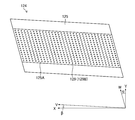
- FIG. 12 is an explanatory diagram of streak defects in a printed matter generated by using a printing unit to which a line head is applied.
- Reference numeral 129C indicates a projection nozzle array in which the matrix-arranged nozzles 129 shown in FIG. 9 are projected in the paper width direction.
- the projection nozzle row 129C shown in FIG. 12 is a substantial nozzle arrangement of the matrix-arranged nozzles 129 shown in FIG.
- Nozzle 129D is a non-ejection nozzle.
- the printed matter 240 in which the image is printed on the paper P has a streak defect 242 at the printing position of the nozzle 129D.
- the illustration of the image of the printed matter 240 is omitted.
- streak defects 242 that are parallel to the paper transport direction and have a length corresponding to the printing range of the nozzle 129D in the paper transport direction may occur.
- the paper transport direction when the line head is provided corresponds to an example of the relative transport direction between the printing unit and the medium.
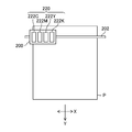
- FIG. 13 is an explanatory diagram of streak defects in a printed matter generated by using a printing unit to which a serial head is applied.
- the plurality of nozzles 229 shown in FIG. 13 correspond to the plurality of nozzle openings 229B shown in FIG.
- Reference numeral 229A indicates a nozzle array having a plurality of nozzles 229 as constituent elements.
- Nozzle 229D is a non-ejection nozzle.
- the printed matter 250 on which the image is printed on the paper P has a streak defect 252 at the printing position of the nozzle 229D.
- the illustration of the image of the printed matter 250 is omitted.
- the streak defect 252 is parallel to the scanning direction of the carriage 200 shown in FIG. 10, and has a length corresponding to the printing range of the nozzle 129D in the scanning direction of the carriage 200.
- the scanning direction of the carriage 200 when the serial head is provided corresponds to an example of the relative transport direction between the printing unit and the medium.
- FIG. 14 is an explanatory diagram of the deep learning model.
- learning is performed using the disturbance imparting learning data set 262 to which the disturbance is added.
- the defect to be inspected is a streak defect generated in the printed matter, and the disturbance is a misalignment of the imaged data with respect to the print data in the direction orthogonal to the streak defect.
- a matching method is applied to find the position where the error is minimized when the pixels are shifted within the search range.
- the accuracy of the alignment process and the period of the alignment process tend to be in a trade-off relationship.
- the period of the alignment process is limited according to the limitation of the inspection period, and it may be difficult to maintain the alignment accuracy.
- the alignment processing period is not limited, perfect alignment is difficult and slight misalignment may occur.
- the training data that has undergone the ideal alignment processing is used for training, robustness against the error of the alignment processing cannot be obtained, and an image structure similar to a streak defect such as a barcode or a grid is obtained. Misalignment in the pattern to be held is easily detected as a streak defect.
- the imaging data in which the position is intentionally shifted with respect to the print data in the direction orthogonal to the direction of the streak defect is applied to the learning data to prevent the misalignment. Has gained robustness.
- the normal learning data set 260 and the disturbance imparting learning data set 262 are input.
- Defect correct answer data 264 is input to the deep learning model 20.
- the defect correct answer data 264 is included in the normal learning data set 260 and the disturbance imparting learning data set 262.
- the normal learning data set 260 and the disturbance imparting learning data set 262 are input, and the defect information of each is output.
- the error calculation unit 35 compares the defect information output from the output layer 34 with the defect correct answer data 264, and outputs the error information.
- the error information is transmitted to the parameter update unit 37.
- the parameter update unit 37 updates the parameters applied to the intermediate layer 32 based on the error information.
- the deep learning model 20 performs learning until a predetermined accuracy is achieved.
- the normal learning data set 260 includes print data and imaging data.
- the normal training data set 260 corresponds to the ideally aligned training data described above.
- the disturbance imparting learning data set 262 includes print data and disturbance imparting imaging data.
- the disturbance imparted imaging data is imaging data whose position is shifted in a direction orthogonal to the direction of the streak defect with respect to the print data. As the print data of the disturbance imparting learning data set 262, the print data of the normal learning data set 260 can be applied.
- the disturbance imparted imaging data is generated by shifting the position of one pixel to three pixels when a maximum deviation of three pixels occurs in the alignment process between the print data and the imaging data. That is, the disturbance imparted imaging data is generated by shifting the position of the imaging data with respect to the print data step by step within the range of the alignment accuracy between the print data and the imaging data.
- the acquisition of the disturbance imparting learning data set 262 shown in the present embodiment may include the generation of the disturbance imparting learning data set 262 that generates the disturbance imparting imaging data from the imaging data.
- the deep learning model 20 performs learning by applying the disturbance imparting learning data set 262 to obtain robustness against a positional deviation between the print data and the imaging data. As a result, it is possible to avoid erroneous detection of streak defects due to misalignment between the print data and the imaging data. In addition, the accuracy of detecting streak defects can be reduced to speed up the inspection of printed matter.
- the normal learning data set 260 and the disturbance imparting learning data set 262 include print data. Defect information of printed matter occurs in the imaged data but not in the printed data. When learning to extract a defect structure is performed, if only the imaging data is used, a pattern structure similar to the defect structure may be recognized as a defect structure. Therefore, by including the print data in the normal learning data set 260 and the disturbance imparting learning data set 262, the performance of the deep learning model 20 can be improved.
- the deep learning model 20 described in the embodiment corresponds to an example of a learning model in which the relationship between the defect candidate detected from the imaging data and the defect in the printed matter is learned.
- FIG. 15 is a flowchart showing a procedure of a learning method applied to the deep learning model shown in FIG.
- the input layer 30 acquires the normal learning data set 260.
- the process proceeds to the disturbance imparting learning data set acquisition step S102.
- the input layer 30 acquires the disturbance imparting learning data set 262. After the disturbance imparting learning data set acquisition step S102, the process proceeds to the defect correct answer data acquisition step S104.
- the disturbance imparting learning data set acquisition step S102 may be performed before the execution of the normal learning data set acquisition step S100.
- the disturbance imparting learning data set acquisition step S102 may be performed in parallel with the normal learning data set acquisition step S100.
- the deep learning model 20 acquires the defect correct answer data 264.
- the learning step S106 is performed after the defect correct answer data acquisition step S104.
- the defect correct answer data acquisition step S104 may be performed before at least one of the normal learning data set acquisition step S100 and the disturbance imparting learning data set acquisition step S102.
- the defect correct answer data acquisition step S104 may be performed in parallel with at least one of the normal learning data set acquisition step S100 and the disturbance imparting learning data set acquisition step S102.
- the deep learning model 20 performs learning using the normal learning data set 260 and the disturbance imparting learning data set 262.
- the learning step S106 includes a defect information output step of outputting defect information, an error calculation step of comparing the defect information with the defect correct answer data 264, and a parameter update step of updating the parameters applied to the intermediate layer 32 based on the comparison result. Is done.
- the process proceeds to the deep learning model updating step S108.
- the deep learning model 20 is updated. After the deep learning model update step S108, the learning method is terminated.
- the learning using the normal learning data set 260 and the disturbance imparting learning data set 262 in combination is illustrated, but even when the learning using only the disturbance imparting learning data set 262 is performed, the print data and the imaging data are combined. It is possible to obtain a certain robustness against misalignment.
- the direction in which the position of the imaging data is shifted with respect to the print data may be a direction that diagonally intersects the direction of the streak defect, and the imaging data may be non-rotating with respect to the print data.
- the direction that intersects the direction of the streak defect may be the direction that intersects the relative transport direction between the printing portion and the paper P.
- the direction orthogonal to the direction of the streak defect can be a substantial nozzle arrangement direction in the printing portion.
- the relative transport direction between the printing unit and the paper P and the substantially nozzle arrangement direction can be set according to the printing method of the printing unit.
- a printed matter is printed using a trained deep learning model that has been trained by inputting a disturbance-imparted learning data set 262 including disturbance-imparted imaging data whose position is shifted with respect to the print data and outputting defect information of streak defects. Inspect for streak defects. This makes it possible to obtain robustness against misalignment of the imaged data with respect to the printed data in the printed matter inspection.
- the disturbance imparting learning data set 262 includes disturbance imparted imaging data whose position is shifted with respect to the print data within the range of alignment accuracy between the print data and the imaging data.
- the deep learning model 20 inputs a normal learning data set 260 including imaging data that is ideally aligned with respect to the print data. Thereby, the accuracy of the deep learning model 20 can be improved.
- the normal learning data set 260 and the disturbance imparting learning data set 262 include print data. As a result, learning for extracting the difference between the imaged data and the print data can be performed, and the performance of the deep learning model 20 can be improved.
- the misalignment of the imaging data with respect to the print data is in a direction orthogonal to the relative transport direction between the printing unit and the paper. As a result, it is possible to obtain robustness against misalignment of the imaging data in the detection of streak defects along the relative transport direction between the printing unit and the paper.
- FIG. 16 is an explanatory diagram of a deep learning model according to an application example.
- learning using the first disturbance imparting learning set 262A and the second disturbance imparting learning set 262B in combination is carried out.
- the image structure of the imaged data may change with respect to the print data, such as a change in the dot pattern caused by the correction of the printing device.
- a change in the image structure of the imaging data with respect to the printing data may occur as a disturbance between the printing data and the imaging data. It is possible to obtain robustness against such a disturbance by performing learning using the imaging data in which a change in the image structure of the imaging data with respect to the print data is given as a disturbance.
- the first disturbance imparting learning set 262A shown in FIG. 16 corresponds to the disturbance imparting learning data set 262 shown in FIG.
- the second disturbance addition learning set 262B is applied to the imaged data with the change in the image structure of the imaged data with respect to the print data as a disturbance.
- the change in the image structure of the imaged data with respect to the print data may be due to the change in the image structure of the printed matter with respect to the print data.
- Examples of such cases include correction processing of the printing unit, excessive or insufficient amount of ink of a specific color with respect to a specified amount, uneven density, noise generated due to the mesh type and the surrounding environment of the printing apparatus, and the like.
- Examples of the correction processing of the printing unit include ejection failure correction processing, nozzle ejection characteristic correction processing such as unevenness correction, and color correction processing.
- An example of an excess or too small amount of ink for a specific color with respect to a specified amount is ink loss such as yellow.
- Examples of density unevenness include transport unevenness of paper P and speed unevenness of carriage 200.
- Examples of net types include AM screens, FM screens, hybrid screens and the like.
- AM is an abbreviation for Amplitude Modulation.
- FM is an abbreviation for Frequency Modulation.
- the net is sometimes called a halftone or the like.
- noise caused by the ambient environment of the printing device examples include noise caused by the ambient temperature of the printing device and noise caused by the ambient humidity of the printing device.
- the image structure of the imaged data obtained by imaging the printed matter subjected to the ejection failure correction process is inconspicuous visually, but the image structure is changed with respect to the printed data.
- such a change in the image structure may be erroneously detected as a defective structure. Therefore, it is possible to learn the change in the image structure of the imaged data with respect to the print data due to the ejection failure correction process as a disturbance and avoid such false detection.
- the change in the image structure of the imaged data with respect to the print data caused by the correction of the nozzle ejection characteristics such as unevenness correction and the correction processing of the printing unit such as color correction can be learned as a disturbance, and such false detection can be avoided.
- the omission of yellow ink can be clearly confirmed in the blue channel of the imaged data, but it may not be visible in the printed matter.
- a printed matter having a defect structure that cannot be visually recognized and a defect structure that is difficult to see may be determined to have no defect structure. Therefore, it is possible to learn as a disturbance the change in the image structure of the imaged data with respect to the print data due to the amount of ink being too small with respect to the specified amount such as ink loss, and avoid such false detection.
- An excess of the specified amount of ink can be dealt with in the same manner as an excess of the specified amount of ink.
- the change in the image structure of the imaging data with respect to the printing data may be due to the characteristics of the imaging device.
- An example of such a case is an individual difference of an image pickup device provided in the image pickup apparatus.
- An example of individual differences in the image sensor is a local change in the resolving power of the image pickup data due to the MTF characteristics and the CTF characteristics of the image pickup device.
- MTF is an abbreviation for Modulation Transfer Function.
- CTF is an abbreviation for Contrast Transfer Function.
- shading occurs in which the edges of the captured data become dark, and the brightness of the edges and non-ends of the captured data when the printed matter is imaged using illumination of uniform brightness. Differences can be mentioned.
- the change in the image structure of the captured data with respect to the printed data may be caused by the paper P applied to the printed matter.
- Examples of such cases include a change in the brightness of the imaging data depending on the type of the paper P, a stain on the paper P, and the like.
- Changes in the image structure of the imaging data with respect to the print data caused by the imaging device and changes in the image structure of the imaging data with respect to the print data caused by the paper P can also be learned as disturbances and erroneous detection can be avoided.
- the second disturbance imparted imaging data set shown in FIG. 16 may be a combination of a plurality of disturbances.
- at least one of the disturbance caused by the change in the image structure of the printed matter with respect to the print data, the disturbance caused by the characteristics of the image sensor, and the disturbance caused by the paper P may be combined.
- a plurality of disturbances may be combined among the disturbances caused by the change in the image structure of the printed matter with respect to the print data.
- the second disturbance imparting learning set 262B including the second disturbance imparting imaging data in which the disturbance caused by the change in the image structure of the imaging data with respect to the print data is imparted is the imaging data for the print data.
- the deep learning model 20A is trained in combination with the first disturbance imparting learning set 262A to which the disturbance caused by the misalignment of is applied. As a result, the deep learning model 20A can obtain robustness against various disturbances.
- the printed matter inspection device 10 provided in the printing device 100 may apply an imaging device that irradiates illumination light from the printed surface of the printed matter and receives the reflected light of the illumination light, or may apply an imaging device that receives the reflected light of the illumination light, or the back surface of the printed surface of the printed matter.
- An image pickup device that irradiates the illumination light from the light source and receives the transmitted light of the illumination light may be applied.
- a program corresponding to the printed matter inspection apparatus and the printed matter inspection method disclosed in the present specification may be configured. That is, it is possible to configure a program that allows the computer to realize the functions of each part shown in FIG. 1 and the functions of each part shown in FIG.
- the imaging data acquisition function corresponding to the imaging data acquisition unit 12 shown in FIG. 1, the print data acquisition function corresponding to the print data acquisition unit 14, the alignment processing function corresponding to the alignment processing unit 15, and the inspection processing unit 16 A program that realizes the corresponding inspection processing function and the output function corresponding to the output unit 18 in the computer can be configured.
- the constituent requirements can be appropriately changed, added, or deleted without departing from the gist of the present invention.
- the present invention is not limited to the embodiments described above, and many modifications can be made by a person having ordinary knowledge in the art within the technical idea of the present invention.
Abstract
Provided are a printed matter inspecting device, a printed matter inspecting method, a program, and a printing apparatus that are capable of reducing false detections during detection of defects that occur along one direction. The present invention is provided with: a print data acquiring unit for acquiring print data; a captured image data acquiring unit for acquiring captured image data of printed matter; an alignment processing unit for aligning the print data and the captured image data by applying a prescribed alignment accuracy; and an inspection processing unit for obtaining defect information of the captured image data on the basis of the print data. The inspection processing unit uses a learning model that has learned by using a disturbance-added learning data set of which the input is disturbance-added captured image data obtained by adding a disturbance that displaces the position of the captured image data in a direction intersecting with the direction of relative conveyance of the printing unit in the printing apparatus and a medium, and of which the output is defect information.
Description
本発明は印刷物検査装置、印刷物検査方法、プログラム及び印刷装置に関する。
The present invention relates to a printed matter inspection device, a printed matter inspection method, a program, and a printing device.
スキャナ等の撮像装置を用いて検査対象を撮像して得られた撮像データと、基準となる基準データとを比較して、検査対象の欠陥を検査する欠陥検査装置が広く用いられている。
Defect inspection devices that inspect defects in the inspection target by comparing the imaging data obtained by imaging the inspection target with an imaging device such as a scanner with the reference reference data are widely used.
欠陥検査装置の応用として、印刷装置を用いて生成された印刷物のスジ及びインクの抜け等に起因する印刷欠陥を検査する印刷物検査装置がある。印刷物検査装置は、印刷装置へ入力される印刷データと、印刷された印刷物を撮像して得られた撮像データとを比較して印刷物における欠陥の有無に基づき、印刷物の良否を判定する。
As an application of the defect inspection device, there is a printed matter inspection device that inspects print defects caused by streaks of printed matter generated by using the printing device and ink omission. The printed matter inspection device compares the print data input to the printed matter with the imaged data obtained by imaging the printed printed matter, and determines the quality of the printed matter based on the presence or absence of defects in the printed matter.
印刷データと撮像データを比較する印刷物検査を実施する際に、基準となる印刷データと検査対象の撮像データとの特性の違いを一致させる前処理が必要となる。前処理の実施において、データフォーマットの違い及びカラープロファイル等の特性の違いなど、多岐にわたる条件が存在し、処理が煩雑であり、長期の処理期間を要する。かかる問題に対し、近年広く利用されている深層学習を活用し、パラメータ設定及び特徴量抽出等の自動化が図られている。
When carrying out a printed matter inspection that compares print data and imaging data, preprocessing is required to match the differences in characteristics between the reference print data and the imaging data to be inspected. In the implementation of preprocessing, there are various conditions such as differences in data formats and differences in characteristics such as color profiles, the processing is complicated, and a long processing period is required. To solve this problem, deep learning, which has been widely used in recent years, has been utilized to automate parameter setting and feature extraction.
特許文献1は、入力画像に対するグループ分類を表すクラスの出力等を実施する学習型画像認識装置が記載されている。同文献に記載の装置は学習済のモデルが適用される。同文献は学習において不足する学習データを増強してサンプル数を増やす手法を開示している。具体的には、画像の変動要素が回転の場合、同装置は規定の回転角度に基づき入力画像を回転させた学習サンプル画像を多数生成し、学習サンプル画像を用いた学習を実施する。
Patent Document 1 describes a learning type image recognition device that outputs a class representing a group classification for an input image. The trained model is applied to the device described in the same document. The document discloses a method of increasing the number of samples by enhancing the learning data lacking in learning. Specifically, when the variable element of the image is rotation, the apparatus generates a large number of learning sample images in which the input image is rotated based on a predetermined rotation angle, and performs learning using the learning sample images.
しかしながら、印刷データと撮像データとの間に位置ずれが生じる場合がある。印刷データと撮像データとの間の位置ずれは、印刷物検査において欠陥が存在していない場合に、印刷物の絵柄を欠陥として検出してしまう誤検出の原因となり得る。
However, there may be a misalignment between the print data and the image capture data. The misalignment between the printed data and the imaged data can cause erroneous detection in which the printed matter is detected as a defect when the printed matter is not inspected for defects.
かかる誤検出は、印刷データと撮像データとの位置合わせを高精度化して解決できるが、かかる位置合わせにおける高精度化と位置合わせ処理の期間の長さとはトレードオフになる。目標の処理期間の達成を優先させる場合、印刷物検査の一定の精度低下を許容しなければならない。
Such false detection can be solved by improving the accuracy of the alignment between the print data and the imaging data, but there is a trade-off between the high accuracy in the alignment and the length of the alignment process. If priority is given to achieving the target processing period, a certain decrease in the accuracy of printed matter inspection must be tolerated.
既存の学習データを回転させて学習データを増強する特許文献1に記載の手法は、スジ等の一方向に沿って発生する欠陥検出の学習モデルを生成する際に、学習が複雑となるばかりでなく、学習モデルの性能の低下が懸念される。
The method described in Patent Document 1 that rotates existing learning data to enhance learning data only complicates learning when generating a learning model for detecting defects that occur in one direction such as streaks. There is a concern that the performance of the learning model will deteriorate.
本発明はこのような事情に鑑みてなされたもので、一方向に沿って発生する欠陥の検出における誤検出を抑制し得る、印刷物検査装置、印刷物検査方法、プログラム及び印刷装置を提供することを目的とする。
The present invention has been made in view of such circumstances, and provides a printed matter inspection device, a printed matter inspection method, a program, and a printing device capable of suppressing erroneous detection in detection of defects occurring in one direction. The purpose.
上記目的を達成するために、次の発明態様を提供する。
In order to achieve the above object, the following aspects of the invention are provided.
第1態様に係る印刷物検査装置は、印刷物を生成する際に印刷装置へ入力される印刷データを取得する印刷データ取得部と、印刷物の撮像データを取得する撮像データ取得部と、規定の位置合わせ精度を適用して印刷データと撮像データとの位置合わせを実施する位置合わせ処理部と、位置合わせ処理部を用いて位置合わせ処理が実施された印刷データ及び撮像データを用いて、印刷データに基づき撮像データの欠陥情報を取得する検査処理部と、を備え、検査処理部は、撮像データから検出される欠陥候補と印刷物における欠陥との関係を学習した学習モデルが適用され、学習モデルは、印刷装置における印刷部と媒体との相対搬送方向と交差する方向に、位置合わせ精度の範囲で撮像データの位置をずらす外乱を付与した外乱付与撮像データを入力とし、外乱付与撮像データの欠陥情報を出力とする外乱付与学習データセットを用いて学習が実施される印刷物検査装置である。
The printed matter inspection device according to the first aspect aligns a print data acquisition unit that acquires print data input to the printing device when generating a printed matter, an imaging data acquisition unit that acquires imaging data of the printed matter, and a specified alignment. Based on the print data, using the alignment processing unit that applies accuracy to align the print data and the imaging data, and the print data and imaging data that have been aligned using the alignment processing unit. An inspection processing unit that acquires defect information of imaging data is provided, and a learning model that learns the relationship between defect candidates detected from imaging data and defects in printed matter is applied to the inspection processing unit, and the learning model is printed. Disturbance imparted imaging data with disturbances that shift the position of the imaging data within the range of alignment accuracy in the direction intersecting the relative transport direction between the printing unit and the medium in the device is input, and defect information of the disturbance imparted imaging data is output. This is a printed matter inspection device in which learning is performed using the disturbance imparting learning data set.
第1態様によれば、印刷装置における印刷部と媒体との相対搬送方向と交差する方向について、印刷データと撮像データとの位置合わせ精度の範囲で印刷データに対する撮像データの位置をずらす外乱を付与した外乱付与撮像データを用いた学習を実施した学習モデルを用いて、印刷物の欠陥を検出する印刷物検査を実施する。これにより、相対搬送方向に沿って発生するスジ欠陥の検出における誤検出を抑制し得る。
According to the first aspect, in the direction intersecting the relative transport direction between the printing unit and the medium in the printing apparatus, a disturbance that shifts the position of the imaging data with respect to the printing data within the range of alignment accuracy between the printing data and the imaging data is applied. A printed matter inspection is performed to detect defects in the printed matter by using a learning model in which the learning is performed using the disturbance imparted imaging data. As a result, erroneous detection in the detection of streak defects generated along the relative transport direction can be suppressed.
印刷装置における印刷部と媒体との相対搬送方向は、固定した印刷部に対して媒体を移動させる方向、固定した媒体に対して印刷部を移動させる方向又は両者を移動させる場合の相対的な方向を含み得る。
The relative transport direction between the printing unit and the medium in the printing apparatus is a direction in which the medium is moved with respect to the fixed printing unit, a direction in which the printing unit is moved with respect to the fixed medium, or a relative direction when both are moved. May include.
第2態様は、第1態様の印刷物検査装置において、学習モデルは、外乱付与学習データセットとして印刷データを併用して学習を実施する構成としてもよい。
In the second aspect, in the printed matter inspection device of the first aspect, the learning model may be configured to perform learning by using print data together as a disturbance imparting learning data set.
第2態様によれば、印刷データと撮像データとの比較結果に基づき、スジ欠陥検出に適用される学習モデルを生成し得る。
According to the second aspect, a learning model applied to streak defect detection can be generated based on the comparison result between the print data and the imaging data.
第3態様は、第1態様又は第2態様の印刷物検査装置において、学習モデルは、印刷データ及び撮像データを入力とし、撮像データの欠陥情報を出力とする通常学習データセットを用いる学習が実施される構成としてもよい。
In the third aspect, in the printed matter inspection device of the first aspect or the second aspect, the learning model is trained using a normal learning data set in which the print data and the imaging data are input and the defect information of the imaging data is output. It may be configured as such.
第3態様によれば、外乱が付与されていない撮像データ及び印刷データに基づく学習を実施し得る。これにより、学習モデルの基本性能を向上させ得る。
According to the third aspect, learning based on imaging data and print data to which no disturbance is applied can be performed. This can improve the basic performance of the learning model.
第4態様は、第1態様から第3態様のいずれか一態様の印刷物検査装置において、撮像データ取得部は、インクジェット印刷装置を用いて生成された印刷物の撮像データを取得する構成としてもよい。
The fourth aspect is the printed matter inspection device of any one of the first to third aspects, and the imaging data acquisition unit may be configured to acquire the imaging data of the printed matter generated by using the inkjet printing apparatus.
第4態様によれば、インクジェット印刷装置を用いて生成された印刷物の欠陥検査を実施し得る。
According to the fourth aspect, defect inspection of printed matter produced by using an inkjet printing device can be performed.
第5態様は、第4態様の印刷物検査装置において、検査処理部は、インクジェット印刷装置に具備される複数のノズルの配置方向と交差する方向に沿って生じる欠陥を表す欠陥情報を取得し、学習モデルは、複数のノズルの配置方向に撮像データの位置をずらす外乱を付与した外乱付与撮像データを用いる学習を実施する構成としてもよい。
In the fifth aspect, in the printed matter inspection device of the fourth aspect, the inspection processing unit acquires and learns defect information representing a defect generated along a direction intersecting the arrangement direction of a plurality of nozzles provided in the inkjet printing device. The model may be configured to perform learning using the disturbance-imparted imaging data in which the disturbance is applied to shift the positions of the imaging data in the arrangement directions of the plurality of nozzles.
第5態様によれば、複数のノズルの配置方向と交差する方向に沿って生じるスジ欠陥の誤検出を抑制し得る。
According to the fifth aspect, it is possible to suppress erroneous detection of streak defects that occur along the directions intersecting the arrangement directions of the plurality of nozzles.
第6態様は、第5態様の印刷物検査装置において、学習モデルは、印刷データに対する撮像データの像構造の変化を外乱として付与した外乱付与撮像データを用いる学習を更に実施する構成としてもよい。
In the sixth aspect, in the printed matter inspection device of the fifth aspect, the learning model may be configured to further perform learning using the disturbance imparted imaging data in which the change in the image structure of the imaging data with respect to the print data is imparted as a disturbance.
第6態様によれば、印刷データに対する印刷物の像構造の変化に起因する欠陥の誤検出を抑制し得る。
According to the sixth aspect, it is possible to suppress erroneous detection of defects caused by changes in the image structure of the printed matter with respect to the printed data.
第7態様は、第6態様の印刷物検査装置において、学習モデルは、印刷装置における補正処理に起因する印刷データに対する撮像データの像構造の変化を外乱として付与した外乱付与撮像データを用いる学習を実施する構成としてもよい。
In the seventh aspect, in the printed matter inspection device of the sixth aspect, the learning model carries out learning using the disturbance imparted imaging data in which the change in the image structure of the imaging data with respect to the print data due to the correction processing in the printing apparatus is given as a disturbance. It may be configured to be used.
第7態様によれば、印刷装置の補正処理に起因して生じる、印刷データに対する印刷物の像構造の変化に起因する欠陥の誤検出を抑制し得る。
According to the seventh aspect, it is possible to suppress erroneous detection of defects caused by changes in the image structure of printed matter with respect to printed data, which are caused by correction processing of the printing apparatus.
第8態様は、第7態様の印刷物検査装置において、学習モデルは、ノズルの不吐補正処理に起因して生じる印刷データに対する撮像データの像構造の変化を外乱として付与した外乱付与撮像データを用いる学習を実施する構成としてもよい。
In the eighth aspect, in the printed matter inspection device of the seventh aspect, the learning model uses the disturbance imparted imaging data in which the change in the image structure of the imaging data with respect to the print data caused by the ejection failure correction processing of the nozzle is given as a disturbance. It may be configured to carry out learning.
第8態様によれば、不吐補正処理に起因して生じる、印刷データに対する印刷物の像構造の変化に起因する欠陥の誤検出を抑制し得る。
According to the eighth aspect, it is possible to suppress erroneous detection of defects caused by changes in the image structure of the printed matter with respect to the printed data, which are caused by the ejection failure correction process.
第9態様は、第6態様から第8態様のいずれか一態様の印刷物検査装置において、学習モデルは、印刷装置に適用される網種の種類に応じた印刷データに対する撮像データの像構造の変化を外乱として付与した外乱付与撮像データを用いる学習を実施する構成としてもよい。
A ninth aspect is the printed matter inspection device according to any one of the sixth to eighth aspects, wherein the learning model is a change in the image structure of the captured data with respect to the printed data according to the type of the mesh type applied to the printing device. It may be configured to carry out learning using the disturbance imparted imaging data in which is assigned as a disturbance.
第9態様によれば、印刷装置に適用される網種の種類に応じて生じる、印刷データに対する印刷物の像構造の変化に起因する欠陥の誤検出を抑制し得る。
According to the ninth aspect, it is possible to suppress erroneous detection of defects caused by changes in the image structure of printed matter with respect to print data, which occur depending on the type of mesh type applied to the printing apparatus.
第10態様は、第6態様の印刷物検査装置において、学習モデルは、撮像データを生成する撮像装置に具備される撮像素子の個体差に応じて生じた印刷データに対する撮像データの像構造の変化を外乱として付与した外乱付与撮像データを用いる学習を実施する構成としてもよい。
In the tenth aspect, in the printed matter inspection device of the sixth aspect, the learning model changes the image structure of the image pickup data with respect to the print data generated according to the individual difference of the image pickup device provided in the image pickup device that generates the image pickup data. It may be configured to carry out learning using the disturbance imparted imaging data given as a disturbance.
第10態様によれば、撮像装置に具備される撮像素子の個体差に応じた印刷物に対する撮像データの像構造の変化に起因する欠陥の誤検出を抑制し得る。
According to the tenth aspect, it is possible to suppress erroneous detection of defects caused by changes in the image structure of the imaged data for the printed matter according to individual differences of the image pickup elements provided in the image pickup apparatus.
第11態様は、第10態様の印刷物検査装置において、学習モデルは、撮像データの輝度変化に応じた印刷データに対する撮像データの像構造の変化を外乱として付与した外乱付与撮像データを用いる学習を実施する構成としてもよい。
In the eleventh aspect, in the printed matter inspection device of the tenth aspect, the learning model performs learning using the disturbance imparted imaging data in which the change in the image structure of the imaging data with respect to the printing data according to the change in the brightness of the imaging data is applied as a disturbance. It may be configured to be used.
第11態様によれば、撮像データの輝度変化に応じた印刷物に対する撮像データの像構造の変化に起因する欠陥の誤検出を抑制し得る。
According to the eleventh aspect, it is possible to suppress erroneous detection of defects caused by a change in the image structure of the imaged data with respect to the printed matter in accordance with the change in the brightness of the imaged data.
第12態様は、第6態様の印刷物検査装置において、学習モデルは、媒体の違いに応じた撮像データの輝度変化に応じた印刷データに対する撮像データの像構造の変化を外乱として付与した外乱付与撮像データを用いる学習を実施する構成としてもよい。
In the twelfth aspect, in the printed matter inspection device of the sixth aspect, the learning model is a disturbance imparted imaging in which a change in the image structure of the imaged data with respect to the printed data according to a change in the brightness of the imaged data according to the difference in the medium is given as a disturbance. It may be configured to carry out learning using data.
第12態様によれば、媒体の違い応じた印刷物に対する撮像データの像構造の変化に起因する欠陥の誤検出を抑制し得る。
According to the twelfth aspect, it is possible to suppress erroneous detection of defects caused by changes in the image structure of the imaged data for the printed matter according to the difference in the medium.
媒体の違いは、媒体の種類の違い及び媒体の個体の違いの両者を含み得る。
Differences in media can include both differences in the type of medium and differences in the individual medium.
第13態様は、第6態様から第12態様のいずれか一態様の印刷物検査装置において、学習モデルは、印刷部の周辺環境に応じたノイズに起因する印刷データに対する撮像データの像構造の変化を外乱として付与した外乱付与撮像データを用いる学習を実施する構成としてもよい。
A thirteenth aspect is the printed matter inspection device according to any one of the sixth to twelfth aspects, wherein the learning model changes the image structure of the imaged data with respect to the printed data due to noise according to the surrounding environment of the printing unit. It may be configured to carry out learning using the disturbance imparted imaging data given as a disturbance.
第13態様によれば、印刷部の周辺環境に応じたノイズに起因して生じる、印刷データに対する印刷物の像構造の変化に起因する欠陥の誤検出を抑制し得る。
According to the thirteenth aspect, it is possible to suppress erroneous detection of defects caused by changes in the image structure of the printed matter with respect to the printed data, which are caused by noise according to the surrounding environment of the printing unit.
第14態様は、第13態様の印刷物検査装置において、学習モデルは、印刷部の周辺環境として印刷部の周辺温度に応じたノイズに起因する印刷データに対する撮像データの像構造の変化を外乱として付与した外乱付与撮像データを用いる学習を実施する構成としてもよい。
In the 14th aspect, in the printed matter inspection device of the 13th aspect, the learning model imparts a change in the image structure of the imaged data to the printed data due to noise according to the ambient temperature of the printing unit as a disturbance as the surrounding environment of the printing unit. It may be configured to carry out learning using the disturbance imparted imaging data.
第14態様によれば、印刷部の周辺温度に応じたノイズに起因して生じる、印刷データに対する印刷物の像構造の変化に起因する欠陥の誤検出を抑制し得る。
According to the fourteenth aspect, it is possible to suppress erroneous detection of defects caused by changes in the image structure of the printed matter with respect to the printed data, which are caused by noise according to the ambient temperature of the printed portion.
第15態様は、第13態様又は第14態様の印刷物検査装置において、学習モデルは、印刷部の周辺環境として印刷部の周辺湿度に応じたノイズに起因する印刷データに対する撮像データの像構造の変化を外乱として付与した外乱付与撮像データを用いる学習を実施する構成としてもよい。
A fifteenth aspect is the change in the image structure of the imaged data with respect to the printed data caused by noise according to the ambient humidity of the printing unit as the surrounding environment of the printing unit in the printed matter inspection device of the thirteenth aspect or the fourteenth aspect. It may be configured to carry out learning using the disturbance imparted imaging data in which is assigned as a disturbance.
第15態様によれば、印刷部の周辺湿度に応じたノイズに起因して生じる、印刷データに対する印刷物の像構造の変化に起因する欠陥の誤検出を抑制し得る。
According to the fifteenth aspect, it is possible to suppress erroneous detection of defects caused by changes in the image structure of printed matter with respect to printed data, which are caused by noise according to the ambient humidity of the printed portion.
第16態様は、第6態様から第15態様のいずれか一態様の印刷物検査装置において、学習モデルは、一画素に適用されるインク量の規定量に対する変化に起因する印刷データに対する撮像データの像構造の変化を外乱として付与した外乱付与撮像データを用いる学習を実施する構成としてもよい。
In the 16th aspect, in the printed matter inspection device according to any one of the 6th to 15th aspects, the learning model is an image of the image of the captured data with respect to the printed data due to the change of the amount of ink applied to one pixel with respect to the specified amount. It may be configured to carry out learning using the disturbance imparted imaging data in which the structural change is imparted as a disturbance.
第16態様によれば、インク量の異常に起因する印刷物の欠陥の誤検出を抑制し得る。
According to the 16th aspect, it is possible to suppress erroneous detection of defects in printed matter caused by an abnormality in the amount of ink.
第17態様は、第6態様から第16態様のいずれか一態様の印刷物検査装置において、学習モデルは、媒体の汚れに起因する印刷データに対する撮像データの像構造の変化を外乱として付与した外乱付与撮像データを用いる学習を実施する構成としてもよい。
In the 17th aspect, in the printed matter inspection device according to any one of the 6th to 16th aspects, the learning model imparts a disturbance as a disturbance to the change in the image structure of the imaged data with respect to the printed data due to the stain on the medium. It may be configured to carry out learning using the imaged data.
第17態様によれば、媒体の汚れに起因する印刷物の欠陥の誤検出を抑制し得る。
According to the seventeenth aspect, erroneous detection of defects in printed matter caused by stains on the medium can be suppressed.
第18態様は、第6態様から第17態様のいずれか一態様の印刷物検査装置において、学習モデルは、印刷物に生じるむらに起因する印刷データに対する撮像データの像構造の変化を外乱として付与した外乱付与撮像データを用いる学習を実施する構成としてもよい。
In the 18th aspect, in the printed matter inspection device according to any one of the 6th to 17th aspects, the learning model is a disturbance in which a change in the image structure of the imaged data with respect to the printed data due to unevenness occurring in the printed matter is given as a disturbance. It may be configured to carry out learning using the given imaging data.
第18態様によれば、印刷物に生じるむらに起因する印刷物の欠陥の誤検出を抑制し得る。
According to the eighteenth aspect, it is possible to suppress erroneous detection of defects in the printed matter caused by unevenness in the printed matter.
第19態様に係る印刷物検査方法は、印刷物を生成する際に印刷装置へ入力される印刷データを取得する印刷データ取得工程と、印刷物の撮像データを取得する撮像データ取得工程と、規定の位置合わせ精度を適用して印刷データと撮像データとの位置合わせを実施する位置合わせ処理工程と、位置合わせ処理工程において位置合わせ処理が実施された印刷データ及び撮像データを用いて、印刷データに基づき撮像データの欠陥情報を取得する検査処理工程と、を含み、検査処理工程は、撮像データから検出される欠陥候補と印刷物における欠陥との関係を学習した学習モデルが適用され、学習モデルは、印刷装置における印刷部と媒体との相対搬送方向と交差する方向に、位置合わせ精度の範囲で撮像データの位置をずらす外乱を付与した外乱付与撮像データを入力とし、外乱付与撮像データの欠陥情報を出力とする外乱付与学習データセットを用いて学習が実施される印刷物検査方法である。
The printed matter inspection method according to the nineteenth aspect includes a print data acquisition step of acquiring print data input to a printing apparatus when producing a printed matter, an imaging data acquisition step of acquiring imaging data of a printed matter, and a predetermined alignment. Imaging data based on the print data using the alignment processing step that applies accuracy to align the print data and the imaging data, and the print data and imaging data that the alignment processing was performed in the alignment processing step. A learning model that learns the relationship between defect candidates detected from imaging data and defects in printed matter is applied to the inspection processing process, which includes an inspection processing step for acquiring defect information of the above, and the learning model is used in a printing device. Disturbance-imposed imaging data with disturbances that shift the position of the imaging data within the range of alignment accuracy in the direction intersecting the relative transport direction between the printing unit and the medium is input, and defect information of the disturbance-imparted imaging data is output. This is a printed matter inspection method in which learning is performed using a disturbance imparting learning data set.
第19態様によれば、第1態様と同様の効果を得ることができる。
According to the 19th aspect, the same effect as that of the 1st aspect can be obtained.
第19態様において、第2態様から第18態様で特定した事項と同様の事項を適宜組み合わせることができる。その場合、印刷物検査装置において特定される処理や機能を担う構成要素は、これに対応する処理や機能を担う印刷物検査方法の構成要素として把握することができる。
In the 19th aspect, the same items as those specified in the 2nd to 18th aspects can be appropriately combined. In that case, the component responsible for the process or function specified in the printed matter inspection device can be grasped as the component of the printed matter inspection method responsible for the corresponding process or function.
第20態様に係るプログラムは、コンピュータに、印刷物を生成する際に印刷装置へ入力される印刷データを取得する印刷データ取得機能、印刷物の撮像データを取得する撮像データ取得機能、規定の位置合わせ精度を適用して印刷データと撮像データとの位置合わせを実施する位置合わせ処理機能、及び位置合わせ処理部を用いて位置合わせ処理が実施された印刷データ及び撮像データを用いて、印刷データに基づき撮像データの欠陥情報を取得する検査処理機能を実現させるプログラムであって、検査処理機能は、撮像データから検出される欠陥候補と印刷物における欠陥との関係を学習した学習モデルが適用され、学習モデルは、印刷装置における印刷部と媒体との相対搬送方向と交差する方向に、位置合わせ精度の範囲で撮像データの位置をずらす外乱を付与した外乱付与撮像データを入力とし、外乱付与撮像データの欠陥情報を出力とする外乱付与学習データセットを用いて学習が実施されるプログラムである。
The program according to the twentieth aspect includes a print data acquisition function for acquiring print data input to a printing device when generating a printed matter, an imaging data acquisition function for acquiring imaging data of the printed matter, and a specified alignment accuracy. Imaging based on print data using the alignment processing function that aligns the print data and the imaging data by applying, and the print data and imaging data that have been aligned using the alignment processing unit. It is a program that realizes an inspection processing function that acquires data defect information. The inspection processing function applies a learning model that learns the relationship between defect candidates detected from imaging data and defects in printed matter, and the learning model is , Disturbance imparted imaging data with disturbance that shifts the position of the imaging data within the range of alignment accuracy in the direction intersecting the relative transport direction between the printing unit and the medium in the printing device is input, and defect information of the disturbance imparted imaging data This is a program in which learning is performed using a disturbance imparting learning data set that outputs.
第20態様によれば、第1態様と同様の効果を得ることができる。
According to the twentieth aspect, the same effect as that of the first aspect can be obtained.
第20態様において、第2態様から第18態様で特定した事項と同様の事項を適宜組み合わせることができる。その場合、印刷物検査装置において特定される処理や機能を担う構成要素は、これに対応する処理や機能を担うプログラムの構成要素として把握することができる。
In the 20th aspect, the same items as those specified in the 2nd to 18th aspects can be appropriately combined. In that case, the component responsible for the process or function specified in the printed matter inspection device can be grasped as the component of the program responsible for the corresponding process or function.
第21態様に係る印刷装置は、印刷物を生成する際に適用される印刷データを取得する印刷データ取得部と、媒体搬送方向へ媒体を搬送する搬送部と、搬送部を用いて搬送される媒体に対して、印刷データに基づく印刷を実施する印刷部と、印刷物の撮像データを取得する撮像データ取得部と、規定の位置合わせ精度を適用して印刷データと撮像データとの位置合わせを実施する位置合わせ処理部と、位置合わせ処理部を用いて位置合わせ処理が実施された印刷データ及び撮像データを用いて、印刷データに基づき撮像データの欠陥情報を取得する検査処理部と、を備え、検査処理部は、撮像データから検出される欠陥候補と印刷物における欠陥との関係を学習した学習モデルが適用され、学習モデルは、印刷部と媒体との相対搬送方向と交差する方向に、位置合わせ精度の範囲で撮像データの位置をずらす外乱を付与した外乱付与撮像データを入力とし、外乱付与撮像データの欠陥情報を出力とする外乱付与学習データセットを用いて学習が実施される印刷装置である。
The printing apparatus according to the 21st aspect is a print data acquisition unit that acquires print data applied when producing a printed matter, a transfer unit that conveys the medium in the medium transfer direction, and a medium that is conveyed using the transfer unit. On the other hand, the printing unit that performs printing based on the print data, the imaging data acquisition unit that acquires the imaging data of the printed matter, and the alignment of the print data and the imaging data by applying the specified alignment accuracy are performed. An inspection processing unit is provided with an alignment processing unit and an inspection processing unit that acquires defect information of the imaging data based on the print data using the print data and the imaging data that have been subjected to the alignment processing using the alignment processing unit. A learning model that learns the relationship between defect candidates detected from imaged data and defects in printed matter is applied to the processing unit, and the learning model has alignment accuracy in the direction that intersects the relative transport direction between the printing unit and the medium. This is a printing device in which learning is performed using a disturbance imparting learning data set that inputs disturbance-imparted imaging data to which the position of the imaging data is shifted within the range of the above and outputs defect information of the disturbance-imparted imaging data.
第21態様によれば、第1態様と同様の効果を得ることができる。
According to the 21st aspect, the same effect as that of the 1st aspect can be obtained.
第21態様において、第2態様から第18態様で特定した事項と同様の事項を適宜組み合わせることができる。その場合、印刷物検査装置において特定される処理や機能を担う構成要素は、これに対応する処理や機能を担う印刷装置の構成要素として把握することができる。
In the 21st aspect, the same items as those specified in the 2nd to 18th aspects can be appropriately combined. In that case, the component responsible for the process or function specified in the printed matter inspection device can be grasped as the component of the printing device responsible for the corresponding process or function.
本発明によれば、印刷装置における印刷部と媒体との相対搬送方向と交差する方向について、印刷データと撮像データとの位置合わせ精度の範囲で印刷データに対する撮像データの位置をずらす外乱を付与した外乱付与撮像データを用いた学習を実施した学習モデルを用いて、印刷物の欠陥を検出する印刷物検査を実施する。これにより、媒体搬送方向に沿って発生する欠陥の検出における誤検出を抑制し得る。
According to the present invention, in the direction intersecting the relative transport direction between the printing unit and the medium in the printing apparatus, a disturbance that shifts the position of the imaging data with respect to the printing data within the range of alignment accuracy between the printing data and the imaging data is applied. A printed matter inspection is performed to detect defects in the printed matter using a learning model that has been trained using the disturbance-imposed imaging data. As a result, erroneous detection in the detection of defects generated along the medium transport direction can be suppressed.
以下、添付図面に従って本発明の好ましい実施の形態について詳説する。本明細書では、同一の構成要素には同一の参照符号を付して、重複する説明は適宜省略する。
Hereinafter, preferred embodiments of the present invention will be described in detail with reference to the accompanying drawings. In the present specification, the same components are designated by the same reference numerals, and duplicate description will be omitted as appropriate.
[印刷物検査装置]
〔全体構成〕
図1は印刷物検査装置の機能ブロック図である。印刷物は用紙に印刷が実施され用紙の印刷領域に画像が形成された状態の用紙を表す。印刷物は乾燥処理等の後処理が実施された用紙Pを含み得る。なお、用紙は符号Pを付して図4に図示する。 [Printed matter inspection device]
〔overall structure〕
FIG. 1 is a functional block diagram of a printed matter inspection device. The printed matter represents a paper in which printing is performed on the paper and an image is formed in the print area of the paper. The printed matter may include paper P that has undergone post-treatment such as drying. The paper is designated by reference numeral P and is shown in FIG.
印刷物検査装置10は、撮像データ取得部12、印刷データ取得部14、位置合わせ処理部15、検査処理部16及び出力部18を備える。印刷物検査装置10は、検査対象の印刷物の欠陥情報を出力する。
The printed matter inspection device 10 includes an imaging data acquisition unit 12, a print data acquisition unit 14, an alignment processing unit 15, an inspection processing unit 16, and an output unit 18. The printed matter inspection device 10 outputs defect information of the printed matter to be inspected.
撮像データ取得部12は、印刷装置を用いて印刷された印刷物を、撮像装置を用いて撮像し、印刷物の撮像データを生成する。撮像装置はスキャナを適用し得る。撮像データはビットマップ形式のデジタルデータ等を適用し得る。
The imaging data acquisition unit 12 captures a printed matter printed using the printing device using the imaging device, and generates imaging data of the printed matter. The image pickup device may be a scanner. Bitmap format digital data or the like can be applied to the captured data.
印刷データ取得部14は、印刷データを取得する。印刷データは、印刷装置を用いて印刷物を生成する際に印刷装置へ入力されるデジタルデータである。印刷データの例として、RIPデータ、PDF形式のデジタルデータ及びTIFF形式のデジタルデータが挙げられる。なお、RIPはRaster Image Processorの省略語である。PDFはPortable Document Formatの省略語である。TIFFはTagged Image File Formatの省略語である。
The print data acquisition unit 14 acquires print data. The print data is digital data input to the printing device when the printed matter is generated by using the printing device. Examples of print data include RIP data, PDF format digital data, and TIFF format digital data. RIP is an abbreviation for Raster Image Processor. PDF is an abbreviation for Portable Document Format. TIFF is an abbreviation for Tagged Image File Format.
位置合わせ処理部15は、印刷データと撮像データとの位置合わせ処理を実施する。位置合わせ処理は、公知の処理を適用しうる。位置合わせ処理部15は位置合わせ処理後のデータを検査処理部16へ送信する。
The alignment processing unit 15 performs alignment processing between the print data and the imaging data. A known process can be applied to the alignment process. The alignment processing unit 15 transmits the data after the alignment processing to the inspection processing unit 16.
検査処理部16は、撮像データ及び印刷データを入力とし、撮像データと印刷データとを比較して印刷物の欠陥情報を生成する、検査処理を実施する。印刷物の欠陥情報は、欠陥の有無、欠陥の位置及び欠陥の認識強度値の少なくともいずれかを適用し得る。
The inspection processing unit 16 inputs the imaging data and the printing data, compares the imaging data with the printing data, and generates defect information of the printed matter, and performs the inspection processing. For the defect information of the printed matter, at least one of the presence / absence of a defect, the position of the defect, and the recognition intensity value of the defect can be applied.
検査処理部16は深層学習モデル20を適用し得る。深層学習モデル20は複数のレイヤ構造を有する。深層学習モデル20は複数のレイヤに対応する複数の重みパラメータを保持する。
The inspection processing unit 16 can apply the deep learning model 20. The deep learning model 20 has a plurality of layer structures. The deep learning model 20 holds a plurality of weight parameters corresponding to the plurality of layers.
深層学習モデル20は、重みパラメータを初期値から最適値へ更新し、未学習モデルから学習済みモデルへ変化し得る。深層学習モデル20は、学習済みモデルに対して再学習を実施してもよい。なお、実施形態に記載の深層学習モデルは学習モデルの一例に相当する。
The deep learning model 20 updates the weight parameter from the initial value to the optimum value, and can change from the unlearned model to the trained model. The deep learning model 20 may perform re-learning on the trained model. The deep learning model described in the embodiment corresponds to an example of a learning model.
出力部18は、印刷物検査の結果として印刷物の欠陥情報を出力する。出力部18は視覚的出力形態を適用し得る。視覚的出力形態の例として、欠陥情報を表す文字情報等を表示装置へ表示させる態様が挙げられる。出力部18は聴覚的出力形態を適用し得る。聴覚的出力形態の例として、欠陥情報を表す音声出力が挙げられる。
The output unit 18 outputs defect information of the printed matter as a result of the printed matter inspection. The output unit 18 may apply a visual output form. An example of the visual output form is a mode in which character information or the like representing defect information is displayed on a display device. The output unit 18 may apply an auditory output form. An example of an auditory output form is an audio output representing defect information.
〔深層学習モデル〕
図2は図1に示す検査処理部に適用される深層学習モデルの説明図である。図2には、深層学習モデルの一例として畳み込みニューラルネットワークを示す。畳み込みニューラルネットワークはCNN(Convolutional Neural Network)と呼ばれる場合がある。 [Deep learning model]
FIG. 2 is an explanatory diagram of a deep learning model applied to the inspection processing unit shown in FIG. FIG. 2 shows a convolutional neural network as an example of a deep learning model. A convolutional neural network is sometimes called a CNN (Convolutional Neural Network).
深層学習モデル20は入力層30、中間層32及び出力層34を含む。入力層30、中間層32及び出力層34はそれぞれ、エッジを用いて複数のノードが結ばれる構造を有する。
The deep learning model 20 includes an input layer 30, an intermediate layer 32, and an output layer 34. The input layer 30, the intermediate layer 32, and the output layer 34 each have a structure in which a plurality of nodes are connected by using edges.
中間層32は、畳み込み層40及びプーリング層42を一セットとする複数セットを含む。中間層32は全結合層44を含む。中間層32は、入力層30を介して入力された撮像データ及び印刷データから特徴を抽出する。中間層32は、撮像データの特徴と印刷データの特徴とを比較して、印刷物の欠陥を検出する。
The intermediate layer 32 includes a plurality of sets including the convolution layer 40 and the pooling layer 42 as one set. The intermediate layer 32 includes a fully connected layer 44. The intermediate layer 32 extracts features from the imaging data and print data input via the input layer 30. The intermediate layer 32 compares the characteristics of the imaging data with the characteristics of the print data to detect defects in the printed matter.
畳み込み層40は、前の層で近くにあるノードに対して規定のフィルタサイズのフィルタを使用した畳み込み演算を実施し、特徴マップを生成する。畳み込み層40は撮像データ及び印刷データからエッジ抽出等の特徴抽出の役割を担う。
The convolution layer 40 performs a convolution operation using a filter of a predetermined filter size on a node nearby in the previous layer to generate a feature map. The convolution layer 40 plays a role of feature extraction such as edge extraction from imaging data and print data.
プーリング層42は、畳み込み層40から出力された特徴マップを規定のプーリングサイズを適用して縮小して新たな特徴マップを生成する。プーリング層42は抽出された特徴が平行移動等に起因する影響を受けないように、ロバスト性を与える役割を担う。全結合層44は、直前の層のノードを全て結合する。
The pooling layer 42 generates a new feature map by reducing the feature map output from the convolution layer 40 by applying a predetermined pooling size. The pooling layer 42 plays a role of imparting robustness so that the extracted features are not affected by translation or the like. The fully connected layer 44 joins all the nodes of the immediately preceding layer.
中間層32は、畳み込み層40及びプーリング層42を一セットとする場合に限らず、畳み込み層40が連続する場合があってもよい。また、中間層32は正規化層が含まれていてもよい。
The intermediate layer 32 is not limited to the case where the convolution layer 40 and the pooling layer 42 are a set, and the convolution layer 40 may be continuous. Further, the intermediate layer 32 may include a normalization layer.
出力層34は、印刷物の欠陥情報を含む印刷物検査結果を出力する。深層学習モデル20は、印刷物の欠陥の有無を分類する場合、欠陥情報は、欠陥有及び欠陥無のそれぞれに対応するスコアを出力し得る。スコアの合計は100パーセントとなる。
The output layer 34 outputs the printed matter inspection result including the defect information of the printed matter. When the deep learning model 20 classifies the presence or absence of defects in printed matter, the defect information can output scores corresponding to each of the presence and absence of defects. The total score is 100%.
本実施形態では、深層学習モデル20として畳み込みニューラルネットワークを例示したが、深層学習モデル20は、任意の画像データから特徴を抽出可能な学習モデルを適用し得る。
In the present embodiment, the convolutional neural network is illustrated as the deep learning model 20, but the deep learning model 20 can apply a learning model capable of extracting features from arbitrary image data.
〔印刷物検査方法の手順〕
図3は図1に示す印刷物検査装置に適用される印刷物検査方法の手順を示すフローチャートである。撮像データ取得工程S10では、図1に示す撮像データ取得部12は撮像データを取得する。撮像データ取得工程S10の後に印刷データ取得工程S12へ進む。 [Procedure of printed matter inspection method]
FIG. 3 is a flowchart showing a procedure of a printed matter inspection method applied to the printed matter inspection apparatus shown in FIG. In the imaging data acquisition step S10, the imagingdata acquisition unit 12 shown in FIG. 1 acquires imaging data. After the imaging data acquisition step S10, the process proceeds to the print data acquisition step S12.
図3は図1に示す印刷物検査装置に適用される印刷物検査方法の手順を示すフローチャートである。撮像データ取得工程S10では、図1に示す撮像データ取得部12は撮像データを取得する。撮像データ取得工程S10の後に印刷データ取得工程S12へ進む。 [Procedure of printed matter inspection method]
FIG. 3 is a flowchart showing a procedure of a printed matter inspection method applied to the printed matter inspection apparatus shown in FIG. In the imaging data acquisition step S10, the imaging
印刷データ取得工程S12では、印刷データ取得部14は印刷データを取得する。印刷データ取得工程S12の後に位置合わせ処理工程S13へ進む。なお、印刷データ取得工程S12は撮像データ取得工程S10の実施前に実施されてもよいし、撮像データ取得工程S10の実施中に実施されてもよい。
In the print data acquisition process S12, the print data acquisition unit 14 acquires print data. After the print data acquisition step S12, the process proceeds to the alignment processing step S13. The print data acquisition step S12 may be carried out before the execution of the imaging data acquisition step S10, or may be carried out during the execution of the imaging data acquisition step S10.
位置合わせ処理工程S13では、位置合わせ処理部15は印刷データと撮像データとの位置合わせ処理を実施する。位置合わせ処理工程S13の後に検査処理工程S14へ進む。
In the alignment processing step S13, the alignment processing unit 15 performs the alignment processing of the print data and the imaging data. After the alignment processing step S13, the process proceeds to the inspection processing step S14.
検査処理工程S14では、検査処理部16は撮像データと印刷データとの比較結果に基づき印刷物の欠陥の有無を識別し、欠陥情報を生成する。検査処理工程S14の後に出力工程S16へ進む。
In the inspection processing step S14, the inspection processing unit 16 identifies the presence or absence of defects in the printed matter based on the comparison result between the imaging data and the print data, and generates defect information. After the inspection processing step S14, the process proceeds to the output step S16.
出力工程S16では、出力部18は検査結果として印刷物の欠陥情報を出力する。出力工程S16において検査結果が出力された後に、印刷物検査装置10は印刷物検査方法を終了する。
In the output process S16, the output unit 18 outputs defect information of the printed matter as an inspection result. After the inspection result is output in the output step S16, the printed matter inspection apparatus 10 ends the printed matter inspection method.
[印刷物検査装置を具備する印刷装置の構成例]
〔全体構成〕
図4は図1に示す印刷物検査装置を具備する印刷装置の全体構成図である。本実施形態では、印刷装置100として、インクジェット方式が適用されるインクジェット印刷装置を例示する。図4に示す符号Yは用紙Pの搬送方向を示す。符号Zは鉛直上方向を表す。以下の説明においても同様である。なお、以下の説明において、用紙Pの搬送方向を用紙搬送方向と記載する場合がある。実施形態に記載の用紙搬送方向は媒体搬送方向の一例に相当する。 [Configuration example of a printing device including a printed matter inspection device]
〔overall structure〕
FIG. 4 is an overall configuration diagram of a printing apparatus including the printed matter inspection apparatus shown in FIG. In the present embodiment, as theprinting device 100, an inkjet printing device to which the inkjet method is applied will be illustrated. The reference numeral Y shown in FIG. 4 indicates the transport direction of the paper P. Reference numeral Z represents a vertical upward direction. The same applies to the following description. In the following description, the transport direction of the paper P may be described as the paper transport direction. The paper transport direction described in the embodiment corresponds to an example of the medium transport direction.
〔全体構成〕
図4は図1に示す印刷物検査装置を具備する印刷装置の全体構成図である。本実施形態では、印刷装置100として、インクジェット方式が適用されるインクジェット印刷装置を例示する。図4に示す符号Yは用紙Pの搬送方向を示す。符号Zは鉛直上方向を表す。以下の説明においても同様である。なお、以下の説明において、用紙Pの搬送方向を用紙搬送方向と記載する場合がある。実施形態に記載の用紙搬送方向は媒体搬送方向の一例に相当する。 [Configuration example of a printing device including a printed matter inspection device]
〔overall structure〕
FIG. 4 is an overall configuration diagram of a printing apparatus including the printed matter inspection apparatus shown in FIG. In the present embodiment, as the
印刷装置100は、搬送部110、印刷部120、撮像部130、乾燥部140、選別部150及び排紙部160を備える。印刷装置100は用紙Pへカラー画像を印刷し、印刷物を生成する。
The printing device 100 includes a transport unit 110, a printing unit 120, an imaging unit 130, a drying unit 140, a sorting unit 150, and a paper ejection unit 160. The printing device 100 prints a color image on the paper P to generate a printed matter.
〔搬送部〕
搬送部110は、給紙部から給紙された用紙Pを用紙搬送方向に沿って搬送する。搬送部110は、従動ローラ112、駆動ローラ114及び搬送ベルト116を備える。なお、給紙部の図示は省略する。 [Transport section]
Thetransport unit 110 transports the paper P fed from the paper feed unit along the paper transport direction. The transport unit 110 includes a driven roller 112, a drive roller 114, and a transport belt 116. The illustration of the paper feed unit is omitted.
搬送部110は、給紙部から給紙された用紙Pを用紙搬送方向に沿って搬送する。搬送部110は、従動ローラ112、駆動ローラ114及び搬送ベルト116を備える。なお、給紙部の図示は省略する。 [Transport section]
The
駆動ローラ114は、水平方向に延びる回転軸を有し、回転軸が回転自在に軸支されている。従動ローラ112は、駆動ローラ114の回転軸と平行な回転軸を有し、回転軸が回転自在に軸支されている。なお、駆動ローラ114の回転軸及び従動ローラ112の回転軸の図示は省略する。
The drive roller 114 has a rotating shaft extending in the horizontal direction, and the rotating shaft is rotatably supported. The driven roller 112 has a rotating shaft parallel to the rotating shaft of the driving roller 114, and the rotating shaft is rotatably supported. The rotation shaft of the drive roller 114 and the rotation shaft of the driven roller 112 are not shown.
搬送ベルト116は、ステンレス製の無端状のベルトを適用し得る。これにより、用紙Pの平坦性を良好に保つことができる。搬送ベルト116は、駆動ローラ114と従動ローラ112とに架け渡されている。
As the transport belt 116, a stainless steel endless belt can be applied. Thereby, the flatness of the paper P can be kept good. The transport belt 116 is bridged between the drive roller 114 and the driven roller 112.
駆動ローラ114の回転軸は、モータの回転軸と連結される。モータの回転に応じて、駆動ローラ114は図4における反時計回りに回転する。従動ローラ112は、駆動ローラ114の回転に従動して同図における反時計回りに回転する。従動ローラ112と駆動ローラ114との回転に応じて、搬送ベルト116は従動ローラ112と駆動ローラ114との間を走行経路に沿って走行する。なお、モータの図示は省略する。
The rotating shaft of the drive roller 114 is connected to the rotating shaft of the motor. In response to the rotation of the motor, the drive roller 114 rotates counterclockwise in FIG. The driven roller 112 rotates counterclockwise in the figure in accordance with the rotation of the drive roller 114. According to the rotation of the driven roller 112 and the driving roller 114, the transport belt 116 travels between the driven roller 112 and the driving roller 114 along the traveling path. The motor is not shown.
搬送ベルト116の搬送面には、給紙部から供給された用紙Pが載置される。搬送部110は、搬送ベルト116に載置された用紙Pを従動ローラ112から駆動ローラ114に向かう搬送経路に沿って搬送し、排紙部160へ受け渡す。用紙Pの搬送経路において、印刷部120、撮像部130、乾燥部140及び選別部150のそれぞれに対向する位置において、用紙Pは印刷面を水平に保持されて搬送される。
Paper P supplied from the paper feed unit is placed on the transport surface of the transport belt 116. The transport unit 110 transports the paper P placed on the transport belt 116 along the transport path from the driven roller 112 to the drive roller 114, and delivers the paper P to the paper discharge unit 160. In the transport path of the paper P, the paper P is transported while the print surface is held horizontally at positions facing each of the printing unit 120, the imaging unit 130, the drying unit 140, and the sorting unit 150.
搬送ベルト116は複数の吸着穴が形成される。複数の吸着穴はポンプを用いて吸引される。これにより、搬送ベルト116の搬送面に載置された用紙Pを搬送面に吸着保持し得る。なお、複数の吸着穴及びポンプの図示は省略する。
A plurality of suction holes are formed in the transport belt 116. The plurality of suction holes are sucked using a pump. As a result, the paper P placed on the transport surface of the transport belt 116 can be attracted and held on the transport surface. It should be noted that the illustration of a plurality of suction holes and the pump is omitted.
〔印刷部〕
印刷部120は、印刷データに基づいて用紙Pに対して印刷を実施し、印刷物を生成する。印刷部120は、インクジェットヘッド122C、インクジェットヘッド122M、インクジェットヘッド122Y及びインクジェットヘッド122Kを備える。インクジェットヘッド122Cは、シアンのインクを用いて印刷を実施する。 [Printing section]
Theprinting unit 120 prints on the paper P based on the print data and generates a printed matter. The printing unit 120 includes an inkjet head 122C, an inkjet head 122M, an inkjet head 122Y, and an inkjet head 122K. The inkjet head 122C prints using cyan ink.
印刷部120は、印刷データに基づいて用紙Pに対して印刷を実施し、印刷物を生成する。印刷部120は、インクジェットヘッド122C、インクジェットヘッド122M、インクジェットヘッド122Y及びインクジェットヘッド122Kを備える。インクジェットヘッド122Cは、シアンのインクを用いて印刷を実施する。 [Printing section]
The
同様に、インクジェットヘッド122M、インクジェットヘッド122Y、インクジェットヘッド122Kのそれぞれは、マゼンタインク、イエローインク及びブラックインクを用いて印刷を実施する。
Similarly, each of the inkjet head 122M, the inkjet head 122Y, and the inkjet head 122K is printed using magenta ink, yellow ink, and black ink.
インクジェットヘッド122C、インクジェットヘッド122M、インクジェットヘッド122Y及びインクジェットヘッド122Kのそれぞれは、搬送ベルト116を用いて支持される用紙Pの搬送経路に沿って一定の間隔をおいて配置される。
Each of the Inkjet Head 122C, Inkjet Head 122M, Inkjet Head 122Y, and Inkjet Head 122K is arranged at regular intervals along the conveying path of the paper P supported by the conveying belt 116.
インクジェットヘッド122C、インクジェットヘッド122M、インクジェットヘッド122Y及びインクジェットヘッド122Kのそれぞれは、用紙搬送方向に沿って上記の順に配置される。なお、インクジェットヘッド122C等の配置順は上記に限定されない。
Each of the Inkjet Head 122C, Inkjet Head 122M, Inkjet Head 122Y and Inkjet Head 122K is arranged in the above order along the paper transport direction. The arrangement order of the inkjet head 122C and the like is not limited to the above.
〔撮像部〕
撮像部130は、印刷済みの用紙Pを撮像する。撮像部130は、用紙搬送方向について印刷部120の下流側の位置に配置される。撮像部130は、スキャナ132を備える。スキャナ132は、用紙Pに印刷された画像を光学的に読み取り、印刷画像の撮像データを生成する。 [Image pickup unit]
Theimage pickup unit 130 takes an image of the printed paper P. The imaging unit 130 is arranged at a position on the downstream side of the printing unit 120 in the paper transport direction. The imaging unit 130 includes a scanner 132. The scanner 132 optically reads the image printed on the paper P and generates the captured data of the printed image.
撮像部130は、印刷済みの用紙Pを撮像する。撮像部130は、用紙搬送方向について印刷部120の下流側の位置に配置される。撮像部130は、スキャナ132を備える。スキャナ132は、用紙Pに印刷された画像を光学的に読み取り、印刷画像の撮像データを生成する。 [Image pickup unit]
The
スキャナ132は、印刷画像の光学像を電気信号に変換する撮像デバイスを備える。撮像デバイスは、CCDイメージセンサ及びCMOSイメージセンサ等を適用し得る。なお、CCDはcharge coupled deviceの省略語である。CMOSはcomplementary metal oxide semiconductorの省略語である。
The scanner 132 includes an imaging device that converts an optical image of a printed image into an electrical signal. As the imaging device, a CCD image sensor, a CMOS image sensor, or the like can be applied. CCD is an abbreviation for charge coupled device. CMOS is an abbreviation for complementary metal oxide semiconductor.
スキャナ132は、照明装置及び信号処理回路を備える。照明装置は光源及び光学系を備える。照明装置は撮像対象に照明光を照射する。信号処理回路は撮像デバイスの出力信号に対して、ノイズ除去及び増幅等の信号処理を実施する。なお、撮像デバイス、照明装置及び信号処理回路の図示は省略する。
The scanner 132 includes a lighting device and a signal processing circuit. The lighting device includes a light source and an optical system. The lighting device irradiates the imaging target with illumination light. The signal processing circuit performs signal processing such as noise removal and amplification on the output signal of the imaging device. The imaging device, the lighting device, and the signal processing circuit are not shown.
撮像部130を用いて取得した撮像データは、印刷部120の補正及び用紙Pに印刷された画像の欠陥検出等に利用し得る。すなわち、撮像部130は印刷物検査装置の構成要素として機能する。なお、印刷済みの用紙Pは印刷物と同義である。以下の説明においても同様である。
The imaging data acquired by using the imaging unit 130 can be used for correction of the printing unit 120, detection of defects in the image printed on the paper P, and the like. That is, the image pickup unit 130 functions as a component of the printed matter inspection device. The printed paper P has the same meaning as the printed matter. The same applies to the following description.
〔乾燥部〕
乾燥部140は、印刷物に対して乾燥処理を実施する。乾燥部140は、用紙搬送方向について撮像部130の下流側の位置に配置される。乾燥部140は、ヒータ142を備える。 [Dry part]
The dryingunit 140 performs a drying process on the printed matter. The drying unit 140 is arranged at a position on the downstream side of the imaging unit 130 in the paper transport direction. The drying unit 140 includes a heater 142.
乾燥部140は、印刷物に対して乾燥処理を実施する。乾燥部140は、用紙搬送方向について撮像部130の下流側の位置に配置される。乾燥部140は、ヒータ142を備える。 [Dry part]
The drying
ヒータ142は、ハロゲンヒータ及び赤外線ヒータ等を適用し得る。ヒータ142は、印刷物を加熱し、印刷物を乾燥させる。乾燥部140は、ファン及びブロア等の送風装置を備え得る。
A halogen heater, an infrared heater, or the like can be applied to the heater 142. The heater 142 heats the printed matter and dries the printed matter. The drying unit 140 may include a blower such as a fan and a blower.
〔選別部〕
選別部150は、印刷物の検査結果に応じて、印刷物を選別する。選別部150は、用紙搬送方向における乾燥部140の下流側の位置に配置される。選別部150は、スタンパ152を備える。 [Sort section]
Thesorting unit 150 sorts the printed matter according to the inspection result of the printed matter. The sorting unit 150 is arranged at a position on the downstream side of the drying unit 140 in the paper transport direction. The sorting unit 150 includes a stamper 152.
選別部150は、印刷物の検査結果に応じて、印刷物を選別する。選別部150は、用紙搬送方向における乾燥部140の下流側の位置に配置される。選別部150は、スタンパ152を備える。 [Sort section]
The
スタンパ152は、印刷物の検査結果に応じて、不良品印刷物の先端エッジにインクを付着させるスタンプ処理を実施する。スタンパ152を用いたスタンプ処理に代わり、不良品印刷物へ付箋を貼り付ける処理を適用し得る。
The stamper 152 performs a stamping process for adhering ink to the tip edge of a defective printed matter according to the inspection result of the printed matter. Instead of the stamping process using the stamper 152, a process of attaching a sticky note to a defective printed matter may be applied.
〔排紙部〕
排紙部160は、印刷物を回収する。排紙部160は、用紙搬送方向における選別部150の下流側の位置であり、搬送部110の搬送経路の終点位置に配置される。排紙部160は、排紙台162を備える。 [Paper ejection section]
Thepaper ejection unit 160 collects the printed matter. The paper ejection unit 160 is a position on the downstream side of the sorting unit 150 in the paper transport direction, and is arranged at the end point position of the transport path of the transport unit 110. The paper ejection unit 160 includes a paper ejection table 162.
排紙部160は、印刷物を回収する。排紙部160は、用紙搬送方向における選別部150の下流側の位置であり、搬送部110の搬送経路の終点位置に配置される。排紙部160は、排紙台162を備える。 [Paper ejection section]
The
排紙台162は、印刷物を積み重ねて載置する。排紙台162は、前用紙当て、後用紙当て及び横用紙当てを備える。排紙台162は印刷物の位置及び向きを調整し、印刷物を積み重ねる。
Printed matter is stacked and placed on the paper output stand 162. The output table 162 includes a front paper pad, a rear paper pad, and a horizontal paper pad. The output table 162 adjusts the position and orientation of the printed matter, and stacks the printed matter.
排紙台162は、昇降装置を備え得る。昇降装置は排紙台162を昇降可能に配置される。昇降装置は、排紙台162に積載される印刷物の増減に連動して昇降が制御される。これにより、排紙台162に積載される印刷物のうち最上位置の印刷物が、常に規定の高さに位置する。
The paper output stand 162 may be provided with an elevating device. The elevating device is arranged so that the paper output table 162 can be elevated and lowered. The elevating device controls elevating and lowering in conjunction with an increase and decrease of printed matter loaded on the output table 162. As a result, the printed matter at the highest position among the printed matter loaded on the output table 162 is always located at the specified height.
〔印刷装置に適用される用紙について〕
用紙Pは、印刷用紙等の紙媒体を適用し得る。用紙Pはフィルム状の樹脂及びフィルム状の金属など、紙以外の材料を用いた媒体を適用し得る。用紙Pは、印刷媒体及び記録媒体などと呼ばれることがある。 [Paper applied to printing equipment]
As the paper P, a paper medium such as printing paper can be applied. As the paper P, a medium using a material other than paper, such as a film-like resin and a film-like metal, can be applied. Paper P may be referred to as a printing medium, a recording medium, or the like.
〔印刷装置の機能ブロック〕
図5は図4に示す印刷装置の機能ブロック図である。印刷装置100は、ユーザインターフェース170及び記憶部172を備える。印刷装置100は統括制御部174、搬送制御部176、印刷制御部178、撮像制御部180、乾燥制御部182、選別制御部184及び排紙制御部186を備える。 [Functional block of printing device]
FIG. 5 is a functional block diagram of the printing apparatus shown in FIG. Theprinting device 100 includes a user interface 170 and a storage unit 172. The printing device 100 includes a general control unit 174, a transport control unit 176, a print control unit 178, an imaging control unit 180, a drying control unit 182, a sorting control unit 184, and a paper ejection control unit 186.
図5は図4に示す印刷装置の機能ブロック図である。印刷装置100は、ユーザインターフェース170及び記憶部172を備える。印刷装置100は統括制御部174、搬送制御部176、印刷制御部178、撮像制御部180、乾燥制御部182、選別制御部184及び排紙制御部186を備える。 [Functional block of printing device]
FIG. 5 is a functional block diagram of the printing apparatus shown in FIG. The
ユーザインターフェース170は、入力部及び表示部を備える。入力部はオペレータが各種情報を入力する際に用いられる操作パネルを備える。表示部はオペレータが参照する各種情報が表示される。表示部はディスプレイ装置を適用し得る。なお、入力部及び表示部の図示は省略する。
The user interface 170 includes an input unit and a display unit. The input unit includes an operation panel used when the operator inputs various information. Various information referred to by the operator is displayed on the display unit. The display unit may apply a display device. It should be noted that the illustration of the input unit and the display unit is omitted.
記憶部172は、印刷装置100の制御に適用されるプログラム及びプログラムの実行に必要な各種のパラメータ等が記憶される。記憶部172は、ハードディスク等の磁気記憶媒体及び半導体記憶媒体等の非一時的記憶媒体を適用し得る。
The storage unit 172 stores a program applied to the control of the printing apparatus 100 and various parameters necessary for executing the program. The storage unit 172 may apply a magnetic storage medium such as a hard disk and a non-temporary storage medium such as a semiconductor storage medium.
統括制御部174は、記憶部172から読み出されたプログラム及び各種パラメータを用いて、印刷装置100の全体の動作を統括制御する。すなわち、統括制御部174は、各制御部へ制御の内容を表す指令信号を送信する。
The integrated control unit 174 controls the overall operation of the printing device 100 by using the program and various parameters read from the storage unit 172. That is, the integrated control unit 174 transmits a command signal indicating the content of control to each control unit.
搬送制御部176は、統括制御部174から送信される指令信号に基づき、搬送部110の動作を制御する。搬送制御部176は、用紙Pの給紙及び排紙、用紙Pの搬送速度を制御する。なお、ここでいう速度は、速度の絶対値を表す速さの概念を含み得る。以下の説明においても同様である。
The transport control unit 176 controls the operation of the transport unit 110 based on the command signal transmitted from the integrated control unit 174. The transport control unit 176 controls the paper feeding and discharging of the paper P and the transport speed of the paper P. The speed referred to here may include the concept of speed representing the absolute value of speed. The same applies to the following description.
印刷制御部178は、統括制御部174から送信される指令信号に基づき、印刷部120の動作を制御する。印刷制御部178は画像処理部を備える。画像処理部は印刷データに対して色分解処理、補正処理及びハーフトーン処理等の画像処理を実施する。補正処理はガンマ補正及び濃度補正等の各種補正を適用し得る。
The print control unit 178 controls the operation of the print unit 120 based on the command signal transmitted from the overall control unit 174. The print control unit 178 includes an image processing unit. The image processing unit performs image processing such as color separation processing, correction processing, and halftone processing on the print data. Various corrections such as gamma correction and density correction can be applied to the correction process.
印刷制御部178は、不吐ノズル情報を参照し、インクジェットヘッド122C等の不吐補正処理を実施する。不吐補正処理では、不吐ノズルの近傍位置の正常ノズルを用いて、不吐ノズルの代替打滴が実施される。ここでいう不吐ノズルは、正常なインク吐出を実施できない異常ノズルが含まれ得る。
The print control unit 178 refers to the ejection failure nozzle information and performs ejection failure correction processing such as the inkjet head 122C. In the ejection failure correction process, alternative dropping of the ejection failure nozzle is performed using a normal nozzle located in the vicinity of the ejection failure nozzle. The non-ejection nozzle referred to here may include an abnormal nozzle that cannot perform normal ink ejection.
印刷制御部178は、駆動電圧生成部を備える。駆動電圧生成部は、インクジェットヘッド122C等の吐出タイミング及びインク吐出量を規定する駆動電圧を生成する。印刷制御部178は駆動電圧供給部を備える。駆動電圧供給部はインクジェットヘッド122C等へ駆動電圧を供給する。
The print control unit 178 includes a drive voltage generation unit. The drive voltage generation unit generates a drive voltage that defines the ejection timing and ink ejection amount of the inkjet head 122C or the like. The print control unit 178 includes a drive voltage supply unit. The drive voltage supply unit supplies a drive voltage to the inkjet head 122C and the like.
撮像制御部180は、統括制御部174から送信される指令信号に基づき、撮像部130の動作を制御する。撮像制御部180は、スキャナ132の撮像領域を印刷物が通過する期間において、スキャナ132を用いて印刷物の読み取りを実施する。
The imaging control unit 180 controls the operation of the imaging unit 130 based on the command signal transmitted from the integrated control unit 174. The image pickup control unit 180 reads the printed matter using the scanner 132 during the period in which the printed matter passes through the image pickup region of the scanner 132.
乾燥制御部182は、統括制御部174から送信される指令信号に基づき、乾燥部140の動作を制御する。乾燥制御部182は、予め設定される乾燥条件に基づき、ヒータ142の動作を制御する。これにより、乾燥部140はヒータ142の加熱処理領域を通過する印刷物を加熱する。
The drying control unit 182 controls the operation of the drying unit 140 based on the command signal transmitted from the integrated control unit 174. The drying control unit 182 controls the operation of the heater 142 based on preset drying conditions. As a result, the drying unit 140 heats the printed matter that passes through the heat treatment region of the heater 142.
選別制御部184は、統括制御部174から送信される指令信号に基づき、選別部150の動作を制御する。選別制御部184は、印刷物検査装置10から出力される印刷物の欠陥情報に基づき印刷物を良品と不良品とに分類する。選別制御部184は、スタンパ152のスタンプ処理領域を通過する印刷物に対して、印刷物が不良品の場合にスタンパ152を動作させてスタンプ処理を実施する。
The sorting control unit 184 controls the operation of the sorting unit 150 based on the command signal transmitted from the integrated control unit 174. The sorting control unit 184 classifies the printed matter into non-defective products and defective products based on the defect information of the printed matter output from the printed matter inspection device 10. The sorting control unit 184 operates the stamper 152 to perform stamp processing on the printed matter passing through the stamp processing area of the stamper 152 when the printed matter is defective.
排紙制御部186は、統括制御部174から送信される指令信号に基づき、排紙部160に具備される排紙台162を用いた印刷物の積載を制御する。排紙台162に排紙され積載された印刷物が不良品の場合、印刷物の先端エッジにインクが付着している。オペレータは、排紙台162に積載された印刷物の中から不良品を特定し得る。
The paper ejection control unit 186 controls the loading of printed matter using the paper ejection table 162 provided in the paper ejection unit 160 based on the command signal transmitted from the integrated control unit 174. When the printed matter discharged and loaded on the paper ejection table 162 is a defective product, ink is attached to the tip edge of the printed matter. The operator can identify defective products from the printed matter loaded on the output table 162.
印刷装置100は印刷物検査装置10を備える。統括制御部174は、印刷物検査装置10を制御する。印刷物検査装置10に具備される撮像データ取得部12は、撮像データとしてスキャナ132の出力信号を取得し得る。印刷物検査装置10に具備される印刷データ取得部14は印刷データを取得する。
The printing device 100 includes a printed matter inspection device 10. The integrated control unit 174 controls the printed matter inspection device 10. The image pickup data acquisition unit 12 provided in the printed matter inspection device 10 can acquire the output signal of the scanner 132 as the image pickup data. The print data acquisition unit 14 provided in the printed matter inspection device 10 acquires print data.
統括制御部174は、印刷物検査装置10から印刷物の欠陥情報を取得する。統括制御部174は、印刷物検査装置10から取得した印刷物の欠陥情報を、選別制御部184へ送信する。選別制御部184は印刷物の欠陥情報を利用して、印刷物の選別制御を実施する。
The integrated control unit 174 acquires defect information of printed matter from the printed matter inspection device 10. The integrated control unit 174 transmits the defect information of the printed matter acquired from the printed matter inspection device 10 to the sorting control unit 184. The sorting control unit 184 uses the defect information of the printed matter to perform sorting control of the printed matter.
[印刷装置及び印刷物検査装置のハードウェア構成]
図1及び図5に示す各処理部は、以下に説明するハードウェアを用いて、規定のプログラムを実行して規定の機能を実現し得る。各処理部のハードウェアは、各種のプロセッサを適用し得る。プロセッサの例として、CPU(Central Processing Unit)及びGPU(Graphics Processing Unit)が挙げられる。CPUはプログラムを実行して各処理部として機能する汎用的なプロセッサである。GPUは画像処理に特化したプロセッサである。プロセッサのハードウェアは、半導体素子等の電気回路素子を組み合わせた電気回路が適用される。各制御部は、プログラム等が記憶されるROM(Read Only Memory)及び各種演算の作業領域等であるRAM(Random Access Memory)を備える。 [Hardware configuration of printing equipment and printed matter inspection equipment]
Each processing unit shown in FIGS. 1 and 5 can execute a specified program and realize a specified function by using the hardware described below. Various processors can be applied to the hardware of each processing unit. Examples of processors include CPUs (Central Processing Units) and GPUs (Graphics Processing Units). The CPU is a general-purpose processor that executes a program and functions as each processing unit. The GPU is a processor specialized in image processing. As the hardware of the processor, an electric circuit in which an electric circuit element such as a semiconductor element is combined is applied. Each control unit includes a ROM (Read Only Memory) in which a program or the like is stored and a RAM (Random Access Memory) in which a work area for various operations or the like is stored.
一つの処理部に対して二つ以上のプロセッサを適用してもよい。二つ以上のプロセッサは、同じ種類のプロセッサでもよいし、異なる種類のプロセッサでもよい。また、複数の処理部に対して一つのプロセッサを適用してもよい。
Two or more processors may be applied to one processing unit. The two or more processors may be the same type of processor or different types of processors. Further, one processor may be applied to a plurality of processing units.
[印刷部の具体例]
次に、図4に示す印刷部120の具体例について説明する。 [Specific example of printing section]
Next, a specific example of theprinting unit 120 shown in FIG. 4 will be described.
次に、図4に示す印刷部120の具体例について説明する。 [Specific example of printing section]
Next, a specific example of the
〔ラインヘッドを備える印刷部〕
図6はラインヘッドが適用される印刷部の構成図である。図6に示すインクジェットヘッド122Cは、用紙搬送方向と直交する用紙幅方向について、用紙Pの全長に対応する長さに渡ってノズルが配置されるラインヘッドが適用される。インクジェットヘッド122M、インクジェットヘッド122Y及びインクジェットヘッド122Kについても同様である。なお、図6に示す符号Xは用紙幅方向を示す。以下の説明においても同様である。 [Printing unit with line head]
FIG. 6 is a block diagram of a printing unit to which the line head is applied. As theinkjet head 122C shown in FIG. 6, a line head in which nozzles are arranged over a length corresponding to the total length of the paper P is applied in the paper width direction orthogonal to the paper transport direction. The same applies to the inkjet head 122M, the inkjet head 122Y, and the inkjet head 122K. The reference numeral X shown in FIG. 6 indicates the paper width direction. The same applies to the following description.
図6はラインヘッドが適用される印刷部の構成図である。図6に示すインクジェットヘッド122Cは、用紙搬送方向と直交する用紙幅方向について、用紙Pの全長に対応する長さに渡ってノズルが配置されるラインヘッドが適用される。インクジェットヘッド122M、インクジェットヘッド122Y及びインクジェットヘッド122Kについても同様である。なお、図6に示す符号Xは用紙幅方向を示す。以下の説明においても同様である。 [Printing unit with line head]
FIG. 6 is a block diagram of a printing unit to which the line head is applied. As the
ここで、本明細書における直交という用語は、二方向が90度未満で交差する場合、又は二方向が90度を超えて交差する場合において、二方向が直交する場合と同様の作用効果を得ることができる実質的な直交を含み得る。平行という用語についても、直交と同様に実質的な平行を含み得る。
Here, the term "orthogonal" in the present specification obtains the same effect as when the two directions are orthogonal when the two directions intersect at less than 90 degrees or when the two directions intersect at more than 90 degrees. It can include a substantial right angle that can be included. The term parallel can also include substantially parallel as well as orthogonal.
図7は図6に示すラインヘッドの構成例を示す斜視図である。以下の説明では、インクジェットヘッド122C、インクジェットヘッド122M、インクジェットヘッド122Y及びインクジェットヘッド122Kを総称してインクジェットヘッド122と呼ぶ。
FIG. 7 is a perspective view showing a configuration example of the line head shown in FIG. In the following description, the inkjet head 122C, the inkjet head 122M, the inkjet head 122Y, and the inkjet head 122K are collectively referred to as the inkjet head 122.
図7に示すインクジェットヘッド122は、インクジェットヘッド122の長手方向について、複数のヘッドモジュール124が一列に並べられた構造を有している。インクジェットヘッド122の長手方向は、インクジェットヘッド122が印刷装置100へ搭載された状態における用紙幅方向に対応する。
The inkjet head 122 shown in FIG. 7 has a structure in which a plurality of head modules 124 are arranged in a row in the longitudinal direction of the inkjet head 122. The longitudinal direction of the inkjet head 122 corresponds to the width direction of the paper when the inkjet head 122 is mounted on the printing apparatus 100.
複数のヘッドモジュール124は支持フレーム126を用いて一体化されて支持される。ヘッドモジュール124はノズル面125の側と反対側にフレキシブル基板128が取り付けられる。
The plurality of head modules 124 are integrated and supported by using the support frame 126. The flexible substrate 128 is attached to the head module 124 on the side opposite to the nozzle surface 125.
ラインヘッドは、フルラインヘッド、ライン型ヘッド及びページワイドヘッドとも呼ばれる。図7に示すラインヘッドの構成は一例である。ラインヘッドは複数のヘッドモジュール124を備える態様に限定されない。また、複数のヘッドモジュール124の配置は図7に示す態様に限定されない。
Line heads are also called full line heads, line type heads and page wide heads. The configuration of the line head shown in FIG. 7 is an example. The line head is not limited to the embodiment including the plurality of head modules 124. Further, the arrangement of the plurality of head modules 124 is not limited to the mode shown in FIG.
図8は図7に示すラインヘッドのノズル面の拡大図である。ヘッドモジュール124のノズル面125は、平行四辺形状とされる。支持フレーム126の両端は、ダミープレート127が取り付けられる。インクジェットヘッド122のノズル面125は、ダミープレート127の表面127Aと合わせて、全体として長方形の形状となる。
FIG. 8 is an enlarged view of the nozzle surface of the line head shown in FIG. The nozzle surface 125 of the head module 124 has a parallel quadrilateral shape. Dummy plates 127 are attached to both ends of the support frame 126. The nozzle surface 125 of the inkjet head 122, together with the surface 127A of the dummy plate 127, has a rectangular shape as a whole.
ヘッドモジュール124のノズル面125の中央部分には、帯状のノズル配置部125Aが具備される。ノズル配置部125Aは、実質的なノズル面125として機能する。ノズルはノズル配置部125Aに備えられる。なお、図8ではノズルを個別に図示せず、複数のノズルから構成されるノズル列129Aを図示する。
A strip-shaped nozzle arrangement portion 125A is provided at the central portion of the nozzle surface 125 of the head module 124. The nozzle arrangement portion 125A functions as a substantial nozzle surface 125. The nozzle is provided in the nozzle arrangement portion 125A. In FIG. 8, the nozzles are not shown individually, but the nozzle row 129A composed of a plurality of nozzles is shown.
図9は図7に示すラインヘッドのノズル配置例を示す平面図である。ヘッドモジュール124のノズル面125には、二次元配置が適用されて複数のノズル開口129Bが配置される。
FIG. 9 is a plan view showing an example of nozzle arrangement of the line head shown in FIG. 7. A two-dimensional arrangement is applied to the nozzle surface 125 of the head module 124, and a plurality of nozzle openings 129B are arranged.
ヘッドモジュール124は、用紙幅方向に対して角度βの傾きを有するV方向に沿った長辺側の端面と、用紙搬送方向に対して角度αの傾きを持つW方向に沿った短辺側の端面とを有する平行四辺形の平面形状とされる。
The head module 124 has an end face on the long side along the V direction having an inclination of an angle β with respect to the paper width direction and a short side along the W direction having an inclination of an angle α with respect to the paper transport direction. It has a plane shape of a parallelogram having an end face.
ヘッドモジュール124は、V方向に沿う行方向、及びW方向に沿う列方向について、複数のノズル開口129Bがマトリクス配置される。ノズル開口129Bは、用紙幅方向に沿う行方向、及び用紙幅方向に対して斜めに交差する列方向に沿って配置されてもよい。
In the head module 124, a plurality of nozzle openings 129B are arranged in a matrix in the row direction along the V direction and the column direction along the W direction. The nozzle openings 129B may be arranged along a row direction along the paper width direction and a column direction diagonally intersecting the paper width direction.
複数のノズル129がマトリクス配置されるインクジェットヘッドの場合、マトリクス配置における各ノズル129をノズル列方向に沿って投影した投影ノズル列は、ノズル列方向について最大の記録解像度を達成する密度で各ノズル129が概ね等間隔で並ぶ一列のノズル列と等価なものと考えることができる。投影ノズル列は、二次元ノズル配置における各ノズル129をノズル列方向に沿って正射影したノズル列である。
In the case of an inkjet head in which a plurality of nozzles 129 are arranged in a matrix, each nozzle 129 projected along the nozzle row direction in the matrix arrangement has a density that achieves the maximum recording resolution in the nozzle row direction. Can be considered to be equivalent to a row of nozzles arranged at approximately equal intervals. The projection nozzle row is a nozzle row in which each nozzle 129 in the two-dimensional nozzle arrangement is projected normally along the nozzle row direction.
概ね等間隔とは、印刷装置100において記録可能な打滴点として実質的に等間隔であることを意味している。例えば、製造上の誤差、及び着弾干渉による基材上での液滴の移動の少なくともいずれか一方を考慮して僅かに間隔を異ならせたものなどが含まれている場合も、等間隔の概念に含まれる。投影ノズル列は実質的なノズル列に相当する。投影ノズル列を考慮すると、ノズル列方向に沿って並ぶ投影ノズルの並び順に、各ノズルにノズル位置を表すノズル番号を対応付けることができる。なお、図9では投影ノズル列の図示は省略する。投影ノズル列は符号129Bを付して図12に図示する。
Approximately equal intervals mean that the printing apparatus 100 has substantially equal intervals as recordable drip points. For example, the concept of equal spacing also includes those that are slightly spaced apart in consideration of at least one of the manufacturing error and the movement of the droplets on the substrate due to landing interference. include. The projected nozzle array corresponds to a substantial nozzle array. Considering the projection nozzle array, it is possible to associate each nozzle with a nozzle number indicating the nozzle position in the order in which the projection nozzles are arranged along the nozzle array direction. In FIG. 9, the projection nozzle row is not shown. The projection nozzle sequence is illustrated with reference numeral 129B in FIG.
インクジェットヘッド122のノズル129の配置形態は限定されず、様々なノズル129の配置形態を採用することができる。例えば、マトリクス状の二次元配置の形態に代えて、一列の直線配置、V字状のノズル配置、及びV字状配置を繰り返し単位とするW字状などのような折れ線状のノズル配置なども可能である。なお、ノズル129は、図9に示すノズル開口129Bが含まれる。上記したノズル129の配置はノズル開口129Bの配置と読み替えてもよい。以下の説明においても同様である。
The arrangement form of the nozzle 129 of the inkjet head 122 is not limited, and various arrangement forms of the nozzle 129 can be adopted. For example, instead of the matrix-like two-dimensional arrangement, a straight line arrangement, a V-shaped nozzle arrangement, and a polygonal line-shaped nozzle arrangement such as a W-shape in which the V-shaped arrangement is a repeating unit are also available. It is possible. The nozzle 129 includes the nozzle opening 129B shown in FIG. The above-mentioned arrangement of the nozzles 129 may be read as the arrangement of the nozzle openings 129B. The same applies to the following description.
ノズル129は、複数のノズル開口129B及び複数のノズル開口129Bのそれぞれと連通する流路を備える。インクジェットヘッド122は、複数のノズル129のそれぞれに対応する加圧素子を備える。加圧素子は圧電素子及び加熱素子を適用し得る。なお、流路、圧電素子及び加熱素子の図示は省略する。
The nozzle 129 includes a flow path that communicates with each of the plurality of nozzle openings 129B and the plurality of nozzle openings 129B. The inkjet head 122 includes a pressurizing element corresponding to each of the plurality of nozzles 129. Piezoelectric elements and heating elements can be applied as the pressurizing element. The flow path, the piezoelectric element, and the heating element are not shown.
すなわち、インクジェットヘッド122は、加圧素子として圧電素子を備えるピエゾジェット方式を適用し得る。インクジェットヘッド122は、加圧素子として加熱素子を備えるサーマル方式を適用し得る。以下に説明するシリアルヘッドについても同様である。
That is, the inkjet head 122 can apply a piezojet method including a piezoelectric element as a pressurizing element. The inkjet head 122 may apply a thermal method including a heating element as a pressurizing element. The same applies to the serial head described below.
〔シリアルヘッドを備える印刷部〕
図10はシリアルヘッドが適用される印刷部の構成例を示す構成図である。図10に示すインクジェットヘッド222C、インクジェットヘッド222M、インクジェットヘッド222Y及びインクジェットヘッド222Kは、用紙搬送方向に沿って複数のノズルが配置されるシリアルヘッドが適用される。なお、図10では、複数のノズルの図示を省略する。複数のノズルは符号229を付して図11に図示する。 [Printing unit with serial head]
FIG. 10 is a configuration diagram showing a configuration example of a printing unit to which the serial head is applied. A serial head in which a plurality of nozzles are arranged along the paper transport direction is applied to theinkjet head 222C, the inkjet head 222M, the inkjet head 222Y, and the inkjet head 222K shown in FIG. In FIG. 10, the illustration of the plurality of nozzles is omitted. The plurality of nozzles are designated by reference numeral 229 and are shown in FIG.
図10はシリアルヘッドが適用される印刷部の構成例を示す構成図である。図10に示すインクジェットヘッド222C、インクジェットヘッド222M、インクジェットヘッド222Y及びインクジェットヘッド222Kは、用紙搬送方向に沿って複数のノズルが配置されるシリアルヘッドが適用される。なお、図10では、複数のノズルの図示を省略する。複数のノズルは符号229を付して図11に図示する。 [Printing unit with serial head]
FIG. 10 is a configuration diagram showing a configuration example of a printing unit to which the serial head is applied. A serial head in which a plurality of nozzles are arranged along the paper transport direction is applied to the
インクジェットヘッド222C、インクジェットヘッド222M、インクジェットヘッド222Y及びインクジェットヘッド222Kは、用紙幅方向に沿って往復移動するキャリッジ200に搭載される。キャリッジ200は、ガイド202を用いて用紙幅方向に沿って往復移動可能に支持される。
The Inkjet Head 222C, Inkjet Head 222M, Inkjet Head 222Y, and Inkjet Head 222K are mounted on a carriage 200 that reciprocates along the paper width direction. The carriage 200 is supported so as to be reciprocally movable along the paper width direction by using the guide 202.
シリアルヘッドを備える印刷部220は、キャリッジを一回以上走査させて、用紙搬送方向に一定の長さを有する一パスの印刷を実施し、一パスの印刷に応じて用紙を搬送させて複数パスの印刷を実施し、一つの画像を印刷する。
The printing unit 220 including the serial head scans the carriage one or more times to print one pass having a certain length in the paper transport direction, and transports the paper according to the printing of one pass to carry a plurality of passes. Is printed, and one image is printed.
図11は図10に示すシリアルヘッドのノズル面の拡大図である。以下の説明では、インクジェットヘッド222C、インクジェットヘッド222M、インクジェットヘッド222Y及びインクジェットヘッド222Kを総称してインクジェットヘッド222と呼ぶ。
FIG. 11 is an enlarged view of the nozzle surface of the serial head shown in FIG. In the following description, the inkjet head 222C, the inkjet head 222M, the inkjet head 222Y, and the inkjet head 222K are collectively referred to as the inkjet head 222.
インクジェットヘッド222は、長手方向に沿って複数のノズル開口229Bが配置される。図11には複数のノズル開口229Bが一列に配置され得る態様を例示したが、複数のノズル開口229Bを二列にジグザクに配置してもよい。
In the inkjet head 222, a plurality of nozzle openings 229B are arranged along the longitudinal direction. Although FIG. 11 illustrates an embodiment in which a plurality of nozzle openings 229B can be arranged in a row, a plurality of nozzle openings 229B may be arranged in two rows in a zigzag manner.
図11の符号230は、ノズル開口229Bと連通する圧力室を表す。ノズル開口229Bは流路を介して圧力室230と連通する。インクジェットヘッド222は、圧力室230へ収容されるインクを加圧して、ノズル開口からインク液滴を吐出させる。なお、符号229はノズルを示す。
Reference numeral 230 in FIG. 11 represents a pressure chamber communicating with the nozzle opening 229B. The nozzle opening 229B communicates with the pressure chamber 230 via a flow path. The inkjet head 222 pressurizes the ink contained in the pressure chamber 230 and ejects ink droplets from the nozzle opening. Reference numeral 229 indicates a nozzle.
[印刷物に生じるスジ欠陥の説明]
印刷物の欠陥の一例としてスジ欠陥が挙げられる。スジ欠陥は、ノズルの吐出異常に起因して、複数のノズルが配置される方向と直交する方向に沿って発生し得る。視認されるスジ欠陥は、印刷物の品質を低下させる。吐出異常が発生したノズルに起因して、スジ欠陥が発生する。以下に、印刷方式ごとのスジ欠陥について説明する。 [Explanation of streak defects in printed matter]
A streak defect can be mentioned as an example of a defect in printed matter. The streak defect may occur along a direction orthogonal to the direction in which the plurality of nozzles are arranged due to the ejection abnormality of the nozzles. Visible streak defects reduce the quality of the printed matter. A streak defect occurs due to the nozzle in which the ejection abnormality has occurred. The streak defects for each printing method will be described below.
〔ラインヘッドの場合〕
図12はラインヘッドが適用される印刷部を用いて生成される印刷物におけるスジ欠陥の説明図である。符号129Cは、図9に示すマトリクス配置されたノズル129を用紙幅方向に投影した投影ノズル列を示す。図12に示す投影ノズル列129Cは、図9に示すマトリクス配置されたノズル129の実質的なノズル配置である。 [For line head]
FIG. 12 is an explanatory diagram of streak defects in a printed matter generated by using a printing unit to which a line head is applied.Reference numeral 129C indicates a projection nozzle array in which the matrix-arranged nozzles 129 shown in FIG. 9 are projected in the paper width direction. The projection nozzle row 129C shown in FIG. 12 is a substantial nozzle arrangement of the matrix-arranged nozzles 129 shown in FIG.
図12はラインヘッドが適用される印刷部を用いて生成される印刷物におけるスジ欠陥の説明図である。符号129Cは、図9に示すマトリクス配置されたノズル129を用紙幅方向に投影した投影ノズル列を示す。図12に示す投影ノズル列129Cは、図9に示すマトリクス配置されたノズル129の実質的なノズル配置である。 [For line head]
FIG. 12 is an explanatory diagram of streak defects in a printed matter generated by using a printing unit to which a line head is applied.
ノズル129Dは不吐ノズルである。用紙Pに画像が印刷された印刷物240は、ノズル129Dの印刷位置にスジ欠陥242が発生している。なお、印刷物240の画像の図示は省略する。ラインヘッドを用いた印刷では、用紙搬送方向に対して平行であり、用紙搬送方向についてノズル129Dの印刷範囲に対応する長さを有するスジ欠陥242が発生し得る。なお、ラインヘッドを備える場合における用紙搬送方向は、印刷部と媒体との相対搬送方向の一例に相当する。
Nozzle 129D is a non-ejection nozzle. The printed matter 240 in which the image is printed on the paper P has a streak defect 242 at the printing position of the nozzle 129D. The illustration of the image of the printed matter 240 is omitted. In printing using the line head, streak defects 242 that are parallel to the paper transport direction and have a length corresponding to the printing range of the nozzle 129D in the paper transport direction may occur. The paper transport direction when the line head is provided corresponds to an example of the relative transport direction between the printing unit and the medium.
〔シリアルヘッドの場合〕
図13はシリアルヘッドが適用される印刷部を用いて生成される印刷物におけるスジ欠陥の説明図である。図13に示す複数のノズル229は、図11に示す複数のノズル開口229Bに対応する。符号229Aは複数のノズル229を構成要素とするノズル列を示す。 [For serial head]
FIG. 13 is an explanatory diagram of streak defects in a printed matter generated by using a printing unit to which a serial head is applied. The plurality ofnozzles 229 shown in FIG. 13 correspond to the plurality of nozzle openings 229B shown in FIG. Reference numeral 229A indicates a nozzle array having a plurality of nozzles 229 as constituent elements.
図13はシリアルヘッドが適用される印刷部を用いて生成される印刷物におけるスジ欠陥の説明図である。図13に示す複数のノズル229は、図11に示す複数のノズル開口229Bに対応する。符号229Aは複数のノズル229を構成要素とするノズル列を示す。 [For serial head]
FIG. 13 is an explanatory diagram of streak defects in a printed matter generated by using a printing unit to which a serial head is applied. The plurality of
ノズル229Dは不吐ノズルである。用紙Pに画像が印刷された印刷物250は、ノズル229Dの印刷位置にスジ欠陥252が発生している。なお、印刷物250の画像の図示は省略する。スジ欠陥252は、図10に示すキャリッジ200の走査方向に対して平行であり、キャリッジ200の走査方向についてノズル129Dの印刷範囲に対応する長さを有している。なお、シリアルヘッドを備える場合におけるキャリッジ200の走査方向は、印刷部と媒体との相対搬送方向の一例に相当する。
Nozzle 229D is a non-ejection nozzle. The printed matter 250 on which the image is printed on the paper P has a streak defect 252 at the printing position of the nozzle 229D. The illustration of the image of the printed matter 250 is omitted. The streak defect 252 is parallel to the scanning direction of the carriage 200 shown in FIG. 10, and has a length corresponding to the printing range of the nozzle 129D in the scanning direction of the carriage 200. The scanning direction of the carriage 200 when the serial head is provided corresponds to an example of the relative transport direction between the printing unit and the medium.
[深層学習モデルの詳細な説明]
図14は深層学習モデルの説明図である。本実施形態に示す深層学習モデル20は、外乱を加えた外乱付与学習データセット262を用いて学習を実施する。これにより、外乱に対するロバスト性が得られる。検査対象の欠陥を印刷物に発生するスジ欠陥とし、外乱はスジ欠陥と直交する方向における印刷データに対する撮像データの位置合わせずれとする。 [Detailed explanation of deep learning model]
FIG. 14 is an explanatory diagram of the deep learning model. In thedeep learning model 20 shown in the present embodiment, learning is performed using the disturbance imparting learning data set 262 to which the disturbance is added. As a result, robustness against disturbance can be obtained. The defect to be inspected is a streak defect generated in the printed matter, and the disturbance is a misalignment of the imaged data with respect to the print data in the direction orthogonal to the streak defect.
図14は深層学習モデルの説明図である。本実施形態に示す深層学習モデル20は、外乱を加えた外乱付与学習データセット262を用いて学習を実施する。これにより、外乱に対するロバスト性が得られる。検査対象の欠陥を印刷物に発生するスジ欠陥とし、外乱はスジ欠陥と直交する方向における印刷データに対する撮像データの位置合わせずれとする。 [Detailed explanation of deep learning model]
FIG. 14 is an explanatory diagram of the deep learning model. In the
一般に、印刷データと撮像データとの位置合わせは、探査範囲内で画素をずらした際に誤差が最小となる位置を求めるマッチング手法が適用される。位置合わせ処理の精度と位置合わせの処理の期間はトレードオフの関係になりやすい。印刷物検査装置10において、リアルタイムに印刷物検査が実施される際に、検査期間の制限に応じて位置合わせの処理の期間が制限され、位置合わせ精度の維持が困難になり得る。
Generally, for the alignment of print data and imaging data, a matching method is applied to find the position where the error is minimized when the pixels are shifted within the search range. The accuracy of the alignment process and the period of the alignment process tend to be in a trade-off relationship. When the printed matter inspection device 10 performs the printed matter inspection in real time, the period of the alignment process is limited according to the limitation of the inspection period, and it may be difficult to maintain the alignment accuracy.
一方、位置合わせの処理の期間が制限されない場合でも、完全な位置合わせは困難であり、わずかに位置ずれが発生し得る。このような場合、理想的な位置合わせ処理がされた学習データのみを学習に使用すると、位置合わせ処理の誤差に対するロバスト性が得られず、バーコード及び格子等のスジ欠陥に類似する像構造を有する絵柄における位置ずれをスジ欠陥とて誤検出しやすくなる。
On the other hand, even if the alignment processing period is not limited, perfect alignment is difficult and slight misalignment may occur. In such a case, if only the training data that has undergone the ideal alignment processing is used for training, robustness against the error of the alignment processing cannot be obtained, and an image structure similar to a streak defect such as a barcode or a grid is obtained. Misalignment in the pattern to be held is easily detected as a streak defect.
そこで、本実施形態に示す深層学習モデル20の学習には、スジ欠陥の方向と直交する方向について、印刷データに対して意図的に位置をずらした撮像データを学習データに適用し、位置ずれに対するロバスト性を得ている。
Therefore, in the learning of the deep learning model 20 shown in the present embodiment, the imaging data in which the position is intentionally shifted with respect to the print data in the direction orthogonal to the direction of the streak defect is applied to the learning data to prevent the misalignment. Has gained robustness.
すなわち、図14に示す深層学習モデル20の学習では、通常学習データセット260及び外乱付与学習データセット262が入力される。深層学習モデル20は欠陥正解データ264が入力される。欠陥正解データ264は、通常学習データセット260及び外乱付与学習データセット262に含まれる。
That is, in the learning of the deep learning model 20 shown in FIG. 14, the normal learning data set 260 and the disturbance imparting learning data set 262 are input. Defect correct answer data 264 is input to the deep learning model 20. The defect correct answer data 264 is included in the normal learning data set 260 and the disturbance imparting learning data set 262.
深層学習モデル20の学習では、通常学習データセット260及び外乱付与学習データセット262を入力とし、それぞれの欠陥情報が出力される。誤差算出部35は、出力層34から出力された欠陥情報と欠陥正解データ264とを比較し、誤差情報を出力する。
In the learning of the deep learning model 20, the normal learning data set 260 and the disturbance imparting learning data set 262 are input, and the defect information of each is output. The error calculation unit 35 compares the defect information output from the output layer 34 with the defect correct answer data 264, and outputs the error information.
誤差情報はパラメータ更新部37へ送信される。パラメータ更新部37は誤差情報に基づき中間層32に適用されるパラメータを更新する。深層学習モデル20は規定の精度が達成されるまで学習を実施する。
The error information is transmitted to the parameter update unit 37. The parameter update unit 37 updates the parameters applied to the intermediate layer 32 based on the error information. The deep learning model 20 performs learning until a predetermined accuracy is achieved.
通常学習データセット260は、印刷データ及び撮像データが含まれる。通常学習データセット260は、上記した理想的な位置合わせがされた学習データに対応する。外乱付与学習データセット262は、印刷データ及び外乱付与撮像データが含まれる。外乱付与撮像データは、印刷データに対してスジ欠陥の方向に対して直交する方向に位置をずらした撮像データである。なお、外乱付与学習データセット262の印刷データは、通常学習データセット260の印刷データを適用し得る。
The normal learning data set 260 includes print data and imaging data. The normal training data set 260 corresponds to the ideally aligned training data described above. The disturbance imparting learning data set 262 includes print data and disturbance imparting imaging data. The disturbance imparted imaging data is imaging data whose position is shifted in a direction orthogonal to the direction of the streak defect with respect to the print data. As the print data of the disturbance imparting learning data set 262, the print data of the normal learning data set 260 can be applied.
外乱付与撮像データは、印刷データと撮像データとの位置合わせ処理において最大で三画素のずれが発生する場合に、一画素から三画素までの間で一画素ずつ位置をずらして生成される。すなわち、外乱付与撮像データは、印刷データと撮像データとの位置合わせ精度の範囲で、段階的に印刷データに対して撮像データの位置をずらして生成される。本実施形態に示す外乱付与学習データセット262の取得は、撮像データから外乱付与撮像データを生成する外乱付与学習データセット262の生成を含み得る。
The disturbance imparted imaging data is generated by shifting the position of one pixel to three pixels when a maximum deviation of three pixels occurs in the alignment process between the print data and the imaging data. That is, the disturbance imparted imaging data is generated by shifting the position of the imaging data with respect to the print data step by step within the range of the alignment accuracy between the print data and the imaging data. The acquisition of the disturbance imparting learning data set 262 shown in the present embodiment may include the generation of the disturbance imparting learning data set 262 that generates the disturbance imparting imaging data from the imaging data.
深層学習モデル20は、外乱付与学習データセット262を適用した学習を実施して、印刷データと撮像データとの位置ずれに対するロバスト性を得ている。これにより、印刷データと撮像データとの位置ずれに起因するスジ欠陥の誤検出を回避し得る。また、スジ欠陥の検出精度を落して印刷物検査の高速化を達成し得る。
The deep learning model 20 performs learning by applying the disturbance imparting learning data set 262 to obtain robustness against a positional deviation between the print data and the imaging data. As a result, it is possible to avoid erroneous detection of streak defects due to misalignment between the print data and the imaging data. In addition, the accuracy of detecting streak defects can be reduced to speed up the inspection of printed matter.
通常学習データセット260及び外乱付与学習データセット262は、印刷データが含まれる。印刷物の欠陥情報は、撮像データに生じるが印刷データには生じない。欠陥構造を抽出する学習を実施する際に、撮像データのみを用いると欠陥構造と類似する絵柄構造を欠陥構造と認識してしまう可能性がある。そこで、通常学習データセット260及び外乱付与学習データセット262に印刷データを含めることで、深層学習モデル20の性能向上が可能となる。
The normal learning data set 260 and the disturbance imparting learning data set 262 include print data. Defect information of printed matter occurs in the imaged data but not in the printed data. When learning to extract a defect structure is performed, if only the imaging data is used, a pattern structure similar to the defect structure may be recognized as a defect structure. Therefore, by including the print data in the normal learning data set 260 and the disturbance imparting learning data set 262, the performance of the deep learning model 20 can be improved.
なお、実施形態に記載の深層学習モデル20は、撮像データから検出される欠陥候補と印刷物における欠陥との関係を学習した学習モデルの一例に相当する。
The deep learning model 20 described in the embodiment corresponds to an example of a learning model in which the relationship between the defect candidate detected from the imaging data and the defect in the printed matter is learned.
〔学習方法の手順〕
図15は図14に示す深層学習モデルに適用される学習方法の手順を示すフローチャートである。通常学習データセット取得工程S100では、入力層30は通常学習データセット260を取得する。通常学習データセット取得工程S100の後に外乱付与学習データセット取得工程S102へ進む。 [Procedure of learning method]
FIG. 15 is a flowchart showing a procedure of a learning method applied to the deep learning model shown in FIG. In the normal learning data set acquisition step S100, theinput layer 30 acquires the normal learning data set 260. After the normal learning data set acquisition step S100, the process proceeds to the disturbance imparting learning data set acquisition step S102.
図15は図14に示す深層学習モデルに適用される学習方法の手順を示すフローチャートである。通常学習データセット取得工程S100では、入力層30は通常学習データセット260を取得する。通常学習データセット取得工程S100の後に外乱付与学習データセット取得工程S102へ進む。 [Procedure of learning method]
FIG. 15 is a flowchart showing a procedure of a learning method applied to the deep learning model shown in FIG. In the normal learning data set acquisition step S100, the
外乱付与学習データセット取得工程S102では、入力層30は外乱付与学習データセット262を取得する。外乱付与学習データセット取得工程S102の後に欠陥正解データ取得工程S104へ進む。
In the disturbance imparting learning data set acquisition step S102, the input layer 30 acquires the disturbance imparting learning data set 262. After the disturbance imparting learning data set acquisition step S102, the process proceeds to the defect correct answer data acquisition step S104.
なお、外乱付与学習データセット取得工程S102は、通常学習データセット取得工程S100の実施前に実施されてもよい。外乱付与学習データセット取得工程S102は、通常学習データセット取得工程S100と並行して実施されてもよい。
Note that the disturbance imparting learning data set acquisition step S102 may be performed before the execution of the normal learning data set acquisition step S100. The disturbance imparting learning data set acquisition step S102 may be performed in parallel with the normal learning data set acquisition step S100.
欠陥正解データ取得工程S104では、深層学習モデル20は欠陥正解データ264を取得する。欠陥正解データ取得工程S104の後に学習工程S106が実施される。なお、欠陥正解データ取得工程S104は、通常学習データセット取得工程S100及び外乱付与学習データセット取得工程S102の少なくともいずれかの実施前に実施されてもよい。
In the defect correct answer data acquisition step S104, the deep learning model 20 acquires the defect correct answer data 264. The learning step S106 is performed after the defect correct answer data acquisition step S104. The defect correct answer data acquisition step S104 may be performed before at least one of the normal learning data set acquisition step S100 and the disturbance imparting learning data set acquisition step S102.
欠陥正解データ取得工程S104は、通常学習データセット取得工程S100及び外乱付与学習データセット取得工程S102の少なくともいずれかと並行して実施されてもよい。
The defect correct answer data acquisition step S104 may be performed in parallel with at least one of the normal learning data set acquisition step S100 and the disturbance imparting learning data set acquisition step S102.
学習工程S106では、深層学習モデル20は通常学習データセット260及び外乱付与学習データセット262を用いた学習を実施する。学習工程S106では、欠陥情報を出力する欠陥情報出力工程、欠陥情報と欠陥正解データ264とを比較する誤差算出工程及び比較結果に基づき中間層32に適用されるパラメータを更新するパラメータ更新工程が含まれる。学習工程S106の後に深層学習モデル更新工程S108へ進む。
In the learning step S106, the deep learning model 20 performs learning using the normal learning data set 260 and the disturbance imparting learning data set 262. The learning step S106 includes a defect information output step of outputting defect information, an error calculation step of comparing the defect information with the defect correct answer data 264, and a parameter update step of updating the parameters applied to the intermediate layer 32 based on the comparison result. Is done. After the learning step S106, the process proceeds to the deep learning model updating step S108.
深層学習モデル更新工程S108では、深層学習モデル20が更新される。深層学習モデル更新工程S108の後に、学習方法は終了される。
In the deep learning model update process S108, the deep learning model 20 is updated. After the deep learning model update step S108, the learning method is terminated.
本実施形態では、通常学習データセット260及び外乱付与学習データセット262を併用する学習を例示したが、外乱付与学習データセット262のみを用いた学習を実施した場合も、印刷データと撮像データとの位置ずれに対する一定のロバスト性をえることが可能である。
In the present embodiment, the learning using the normal learning data set 260 and the disturbance imparting learning data set 262 in combination is illustrated, but even when the learning using only the disturbance imparting learning data set 262 is performed, the print data and the imaging data are combined. It is possible to obtain a certain robustness against misalignment.
〔印刷データに対して撮像データの位置をずらす方向について〕
印刷データに対して撮像データの位置をずらす方向は、スジ欠陥の方向と斜めに交差する方向でもよく、印刷データに対して撮像データを非回転であればよい。スジ欠陥の方向と交差する方向は、印刷部と用紙Pとの相対搬送方向に交差する方向とし得る。 [Direction to shift the position of the imaging data with respect to the print data]
The direction in which the position of the imaging data is shifted with respect to the print data may be a direction that diagonally intersects the direction of the streak defect, and the imaging data may be non-rotating with respect to the print data. The direction that intersects the direction of the streak defect may be the direction that intersects the relative transport direction between the printing portion and the paper P.
また、スジ欠陥の方向と直交する方向は、印刷部における実質的なノズルの配置方向とし得る。印刷部と用紙Pとの相対搬送方向及び実質的なノズルの配置方向は、印刷部の印刷方式に応じて設定し得る。
Further, the direction orthogonal to the direction of the streak defect can be a substantial nozzle arrangement direction in the printing portion. The relative transport direction between the printing unit and the paper P and the substantially nozzle arrangement direction can be set according to the printing method of the printing unit.
[作用効果]
実施形態に係る印刷物検査装置10、印刷物検査方法及び印刷装置100によれば、以下の作用効果を得ることが可能である。 [Action effect]
According to the printedmatter inspection device 10, the printed matter inspection method, and the printing device 100 according to the embodiment, the following effects can be obtained.
実施形態に係る印刷物検査装置10、印刷物検査方法及び印刷装置100によれば、以下の作用効果を得ることが可能である。 [Action effect]
According to the printed
〔1〕
印刷データに対して位置をずらした外乱付与撮像データを含む外乱付与学習データセット262を入力とし、スジ欠陥の欠陥情報を出力とする学習を実施した学習済みの深層学習モデルを用いて、印刷物のスジ欠陥の有無を検査する。これにより、印刷物検査において、印刷データに対する撮像データの位置ずれに対するロバスト性を得ることが可能となる。 [1]
A printed matter is printed using a trained deep learning model that has been trained by inputting a disturbance-impartedlearning data set 262 including disturbance-imparted imaging data whose position is shifted with respect to the print data and outputting defect information of streak defects. Inspect for streak defects. This makes it possible to obtain robustness against misalignment of the imaged data with respect to the printed data in the printed matter inspection.
印刷データに対して位置をずらした外乱付与撮像データを含む外乱付与学習データセット262を入力とし、スジ欠陥の欠陥情報を出力とする学習を実施した学習済みの深層学習モデルを用いて、印刷物のスジ欠陥の有無を検査する。これにより、印刷物検査において、印刷データに対する撮像データの位置ずれに対するロバスト性を得ることが可能となる。 [1]
A printed matter is printed using a trained deep learning model that has been trained by inputting a disturbance-imparted
〔2〕
外乱付与学習データセット262は、印刷データと撮像データとの位置合わせ精度の範囲で印刷データに対して位置をずらした外乱付与撮像データが含まれる。これにより、印刷物検査において、印刷データと撮像データとの位置合わせ精度の範囲の位置ずれに対するロバスト性を得ることができる。 [2]
The disturbance imparting learningdata set 262 includes disturbance imparted imaging data whose position is shifted with respect to the print data within the range of alignment accuracy between the print data and the imaging data. As a result, in the printed matter inspection, it is possible to obtain robustness against misalignment within the range of alignment accuracy between the printed data and the imaging data.
外乱付与学習データセット262は、印刷データと撮像データとの位置合わせ精度の範囲で印刷データに対して位置をずらした外乱付与撮像データが含まれる。これにより、印刷物検査において、印刷データと撮像データとの位置合わせ精度の範囲の位置ずれに対するロバスト性を得ることができる。 [2]
The disturbance imparting learning
〔3〕
深層学習モデル20は、印刷データに対して理想的な位置合わせがされた撮像データを含む通常学習データセット260を入力とする。これにより、深層学習モデル20の精度が向上し得る。 [3]
Thedeep learning model 20 inputs a normal learning data set 260 including imaging data that is ideally aligned with respect to the print data. Thereby, the accuracy of the deep learning model 20 can be improved.
深層学習モデル20は、印刷データに対して理想的な位置合わせがされた撮像データを含む通常学習データセット260を入力とする。これにより、深層学習モデル20の精度が向上し得る。 [3]
The
〔4〕
通常学習データセット260及び外乱付与学習データセット262は、印刷データが含まれる。これにより、印刷データに対する撮像データの差分を抽出する学習を実施でき、深層学習モデル20の性能向上が可能となる。 [4]
The normallearning data set 260 and the disturbance imparting learning data set 262 include print data. As a result, learning for extracting the difference between the imaged data and the print data can be performed, and the performance of the deep learning model 20 can be improved.
通常学習データセット260及び外乱付与学習データセット262は、印刷データが含まれる。これにより、印刷データに対する撮像データの差分を抽出する学習を実施でき、深層学習モデル20の性能向上が可能となる。 [4]
The normal
〔5〕
印刷データに対する撮像データの位置ずれは、印刷部と用紙との相対搬送方向に直交する方向とする。これにより、印刷部と用紙との相対搬送方向に沿うスジ欠陥の検出において、撮像データの位置ずれに対するロバスト性を得ることができる。 [5]
The misalignment of the imaging data with respect to the print data is in a direction orthogonal to the relative transport direction between the printing unit and the paper. As a result, it is possible to obtain robustness against misalignment of the imaging data in the detection of streak defects along the relative transport direction between the printing unit and the paper.
ライン型ヘッドが適用される印刷部を備える場合、用紙搬送方向に沿うスジ欠陥の検出において、撮像データの位置ずれに対するロバスト性を得ることができる。
When a printing unit to which a line type head is applied is provided, robustness against misalignment of imaging data can be obtained in detecting streak defects along the paper transport direction.
シリアル型ヘッドが適用される印刷部を備える場合、キャリッジ200の走査方向に沿うスジ欠陥の検出において、撮像データの位置ずれに対するロバスト性を得ることができる。
When a printing unit to which a serial type head is applied is provided, robustness against misalignment of imaging data can be obtained in detecting streak defects along the scanning direction of the carriage 200.
[応用例]
図16は応用例に係る深層学習モデルの説明図である。応用例に係る印刷物検査装置に具備される深層学習モデル20Aは、第一外乱付与学習セット262Aと第二外乱付与学習セット262Bとを併用する学習が実施される。 [Application example]
FIG. 16 is an explanatory diagram of a deep learning model according to an application example. In thedeep learning model 20A provided in the printed matter inspection device according to the application example, learning using the first disturbance imparting learning set 262A and the second disturbance imparting learning set 262B in combination is carried out.
図16は応用例に係る深層学習モデルの説明図である。応用例に係る印刷物検査装置に具備される深層学習モデル20Aは、第一外乱付与学習セット262Aと第二外乱付与学習セット262Bとを併用する学習が実施される。 [Application example]
FIG. 16 is an explanatory diagram of a deep learning model according to an application example. In the
印刷データは印刷装置100の状態に関わらず不変であるのに対して、撮像データは印刷装置の補正等に起因するドットパターンの変化など、印刷データに対する撮像データにおける像構造の変化が生じ得る。
While the print data is unchanged regardless of the state of the printing device 100, the image structure of the imaged data may change with respect to the print data, such as a change in the dot pattern caused by the correction of the printing device.
すなわち、印刷データと撮像データとの間には、印刷データに対する撮像データの像構造の変化が外乱として生じ得る。印刷データに対する撮像データの像構造の変化を外乱として付与した撮像データを用いる学習を実施して、かかる外乱に対するロバスト性を得ることができる。
That is, a change in the image structure of the imaging data with respect to the printing data may occur as a disturbance between the printing data and the imaging data. It is possible to obtain robustness against such a disturbance by performing learning using the imaging data in which a change in the image structure of the imaging data with respect to the print data is given as a disturbance.
図16に示す第一外乱付与学習セット262Aは、図14に示す外乱付与学習データセット262に相当する。第二外乱付与学習セット262Bは、印刷データに対する撮像データの像構造の変化を外乱として、撮像データに対して付与される。
The first disturbance imparting learning set 262A shown in FIG. 16 corresponds to the disturbance imparting learning data set 262 shown in FIG. The second disturbance addition learning set 262B is applied to the imaged data with the change in the image structure of the imaged data with respect to the print data as a disturbance.
印刷データに対する撮像データの像構造の変化は、印刷データに対する印刷物の像構造の変化に起因する場合がある。かかる場合の例として、印刷部の補正処理、特定色のインク量の規定量に対する過多又は過少、濃度むら、網種及び印刷装置の周辺環境に起因して生じるノイズ等が挙げられる。
The change in the image structure of the imaged data with respect to the print data may be due to the change in the image structure of the printed matter with respect to the print data. Examples of such cases include correction processing of the printing unit, excessive or insufficient amount of ink of a specific color with respect to a specified amount, uneven density, noise generated due to the mesh type and the surrounding environment of the printing apparatus, and the like.
印刷部の補正処理の例として、不吐補正処理、むら補正等のノズルの吐出特性の補正処理及び色補正処理等が挙げられる。特定色のインク量の規定量に対する過多又は過少の例として、イエロー等のインク抜けが挙げられる。
Examples of the correction processing of the printing unit include ejection failure correction processing, nozzle ejection characteristic correction processing such as unevenness correction, and color correction processing. An example of an excess or too small amount of ink for a specific color with respect to a specified amount is ink loss such as yellow.
濃度むらの例として、用紙Pの搬送むら及びキャリッジ200の速度むら等が挙げられる。網種の例として、AMスクリーン、FMスクリーン及びハイブリッドスクリーン等が挙げられる。AMはAmplitude Modulationの省略語である。FMはFrequency Modulationの省略語である。なお、網はハーフトーン等と呼ばれることがある。
Examples of density unevenness include transport unevenness of paper P and speed unevenness of carriage 200. Examples of net types include AM screens, FM screens, hybrid screens and the like. AM is an abbreviation for Amplitude Modulation. FM is an abbreviation for Frequency Modulation. The net is sometimes called a halftone or the like.
印刷装置の周辺環境に起因して生じるノイズの例として、印刷装置の周辺温度に起因して生じるノイズ及び印刷装置の周辺湿度に起因して生じるノイズが挙げられる。
Examples of noise caused by the ambient environment of the printing device include noise caused by the ambient temperature of the printing device and noise caused by the ambient humidity of the printing device.
例えば、不吐補正処理が実施された印刷物を撮像した撮像データは、目視では目立たないが印刷データに対して像構造が変化している。印刷物検査では、かかる像構造の変化を欠陥構造として誤検出する可能性がある。そこで、不吐補正処理に起因する印刷データに対する撮像データの像構造の変化を外乱として学習し、かかる誤検出を回避し得る。
For example, the image structure of the imaged data obtained by imaging the printed matter subjected to the ejection failure correction process is inconspicuous visually, but the image structure is changed with respect to the printed data. In the printed matter inspection, such a change in the image structure may be erroneously detected as a defective structure. Therefore, it is possible to learn the change in the image structure of the imaged data with respect to the print data due to the ejection failure correction process as a disturbance and avoid such false detection.
同様に、むら補正等のノズルの吐出特性の補正及び色補正等の印刷部の補正処理に起因する印刷データに対する撮像データの像構造の変化を外乱として学習し、かかる誤検出を回避し得る。
Similarly, the change in the image structure of the imaged data with respect to the print data caused by the correction of the nozzle ejection characteristics such as unevenness correction and the correction processing of the printing unit such as color correction can be learned as a disturbance, and such false detection can be avoided.
また、イエローインクの抜けは、撮像データのブルーチャンネルにおいてはっきりと確認できるが、印刷物においては視認できない場合があり得る。視認できない欠陥構造及び視認しにくい欠陥構造を有する印刷物は、欠陥構造がないと判定してもよい。そこで、インク抜け等のインク量の規定量に対する過少に起因する印刷データに対する撮像データの像構造の変化を外乱として学習し、かかる誤検出を回避し得る。インク量の規定量に対する過多についてもインク量の規定量に対する過少と同様の対応が可能である。
Also, the omission of yellow ink can be clearly confirmed in the blue channel of the imaged data, but it may not be visible in the printed matter. A printed matter having a defect structure that cannot be visually recognized and a defect structure that is difficult to see may be determined to have no defect structure. Therefore, it is possible to learn as a disturbance the change in the image structure of the imaged data with respect to the print data due to the amount of ink being too small with respect to the specified amount such as ink loss, and avoid such false detection. An excess of the specified amount of ink can be dealt with in the same manner as an excess of the specified amount of ink.
印刷データに対する撮像データの像構造の変化は、撮像装置の特性に起因する場合がある。かかる場合の例として、撮像装置に具備される撮像素子の個体差が挙げられる。撮像素子の個体差の例として、撮像装置のMTF特性及びCTF特性に起因する撮像データにおける解像力の局所的な変化が挙げられる。なお、MTFはModulation Transfer Functionの省略語である。CTFはContrast Transfer Functionの省略語である。
The change in the image structure of the imaging data with respect to the printing data may be due to the characteristics of the imaging device. An example of such a case is an individual difference of an image pickup device provided in the image pickup apparatus. An example of individual differences in the image sensor is a local change in the resolving power of the image pickup data due to the MTF characteristics and the CTF characteristics of the image pickup device. MTF is an abbreviation for Modulation Transfer Function. CTF is an abbreviation for Contrast Transfer Function.
かかる場合の他の例として、撮像データの端が暗くなるシェーディングが発生し、一様な明るさの照明を用いて印刷物を撮像した際の、撮像データの端部と非端部との明るさの相違が挙げられる。
As another example of such a case, shading occurs in which the edges of the captured data become dark, and the brightness of the edges and non-ends of the captured data when the printed matter is imaged using illumination of uniform brightness. Differences can be mentioned.
印刷データに対する撮像データの像構造の変化は、印刷物に適用される用紙Pに起因する場合がある。かかる場合の例として、用紙Pの種類に依存する撮像データの輝度変化及び用紙Pの汚れ等が挙げられる。
The change in the image structure of the captured data with respect to the printed data may be caused by the paper P applied to the printed matter. Examples of such cases include a change in the brightness of the imaging data depending on the type of the paper P, a stain on the paper P, and the like.
撮像装置に起因する印刷データに対する撮像データの像構造の変化及び用紙Pに起因する印刷データに対する撮像データの像構造の変化についても、外乱として学習し、誤検出を回避し得る。
Changes in the image structure of the imaging data with respect to the print data caused by the imaging device and changes in the image structure of the imaging data with respect to the print data caused by the paper P can also be learned as disturbances and erroneous detection can be avoided.
図16に示す第二外乱付与撮像データセットは、複数の外乱を組み合わせてもよい。例えば、印刷データに対する印刷物の像構造の変化に起因する外乱と、撮像素子の特性に起因する外乱及び用紙Pに起因する外乱の少なくともいずれかと、を組み合わせてもよい。また、印刷データに対する印刷物の像構造の変化に起因する外乱のうち、複数の外乱を組み合わせてもよい。
The second disturbance imparted imaging data set shown in FIG. 16 may be a combination of a plurality of disturbances. For example, at least one of the disturbance caused by the change in the image structure of the printed matter with respect to the print data, the disturbance caused by the characteristics of the image sensor, and the disturbance caused by the paper P may be combined. Further, among the disturbances caused by the change in the image structure of the printed matter with respect to the print data, a plurality of disturbances may be combined.
[応用例の作用効果]
応用例に係る印刷物検査装置によれば、印刷データに対する撮像データの像構造の変化に起因する外乱を付与した第二外乱付与撮像データを含む第二外乱付与学習セット262Bを、印刷データに対する撮像データの位置ずれに起因する外乱を付与した第一外乱付与学習セット262Aと併用して、深層学習モデル20Aの学習を実施する。これにより、深層学習モデル20Aは、様々な外乱に対するロバスト性を得ることが可能となる。 [Action and effect of application example]
According to the printed matter inspection apparatus according to the application example, the second disturbance impartinglearning set 262B including the second disturbance imparting imaging data in which the disturbance caused by the change in the image structure of the imaging data with respect to the print data is imparted is the imaging data for the print data. The deep learning model 20A is trained in combination with the first disturbance imparting learning set 262A to which the disturbance caused by the misalignment of is applied. As a result, the deep learning model 20A can obtain robustness against various disturbances.
応用例に係る印刷物検査装置によれば、印刷データに対する撮像データの像構造の変化に起因する外乱を付与した第二外乱付与撮像データを含む第二外乱付与学習セット262Bを、印刷データに対する撮像データの位置ずれに起因する外乱を付与した第一外乱付与学習セット262Aと併用して、深層学習モデル20Aの学習を実施する。これにより、深層学習モデル20Aは、様々な外乱に対するロバスト性を得ることが可能となる。 [Action and effect of application example]
According to the printed matter inspection apparatus according to the application example, the second disturbance imparting
[印刷装置の応用例]
印刷装置100の用紙Pの搬送方式は、搬送ドラムを用いた搬送方式を適用し得る。印刷装置100に具備される印刷物検査装置10は、印刷物の印刷面から照明光を照射して、照明光の反射光を受光する撮像装置を適用してもよいし、印刷物の印刷面の裏側面から照明光を照射して、照明光の透過光を受光する撮像装置を適用してもよい。 [Application example of printing device]
As the transfer method of the paper P of theprinting apparatus 100, a transfer method using a transfer drum can be applied. The printed matter inspection device 10 provided in the printing device 100 may apply an imaging device that irradiates illumination light from the printed surface of the printed matter and receives the reflected light of the illumination light, or may apply an imaging device that receives the reflected light of the illumination light, or the back surface of the printed surface of the printed matter. An image pickup device that irradiates the illumination light from the light source and receives the transmitted light of the illumination light may be applied.
印刷装置100の用紙Pの搬送方式は、搬送ドラムを用いた搬送方式を適用し得る。印刷装置100に具備される印刷物検査装置10は、印刷物の印刷面から照明光を照射して、照明光の反射光を受光する撮像装置を適用してもよいし、印刷物の印刷面の裏側面から照明光を照射して、照明光の透過光を受光する撮像装置を適用してもよい。 [Application example of printing device]
As the transfer method of the paper P of the
[プログラム発明への適用例]
本明細書に開示した印刷物検査装置及び印刷物検査方法に対応するプログラムを構成し得る。すなわち、図1に示す各部の機能及び図5に示す各部の機能をコンピュータに実現させるプログラムを構成し得る。 [Example of application to program invention]
A program corresponding to the printed matter inspection apparatus and the printed matter inspection method disclosed in the present specification may be configured. That is, it is possible to configure a program that allows the computer to realize the functions of each part shown in FIG. 1 and the functions of each part shown in FIG.
例えば、図1に示す撮像データ取得部12に対応する撮像データ取得機能、印刷データ取得部14に対応する印刷データ取得機能、位置合わせ処理部15に対応する位置合わせ処理機能、検査処理部16に対応する検査処理機能及び出力部18に対応する出力機能をコンピュータに実現させるプログラムを構成し得る。
For example, the imaging data acquisition function corresponding to the imaging data acquisition unit 12 shown in FIG. 1, the print data acquisition function corresponding to the print data acquisition unit 14, the alignment processing function corresponding to the alignment processing unit 15, and the inspection processing unit 16 A program that realizes the corresponding inspection processing function and the output function corresponding to the output unit 18 in the computer can be configured.
以上説明した本発明の実施形態は、本発明の趣旨を逸脱しない範囲で、適宜構成要件を変更、追加、削除することが可能である。本発明は以上説明した実施形態に限定されるものではなく、本発明の技術的思想内で当該分野の通常の知識を有する者により、多くの変形が可能である。
In the embodiment of the present invention described above, the constituent requirements can be appropriately changed, added, or deleted without departing from the gist of the present invention. The present invention is not limited to the embodiments described above, and many modifications can be made by a person having ordinary knowledge in the art within the technical idea of the present invention.
10 印刷物検査装置
12 撮像データ取得部
14 印刷データ取得部
16 検査処理部
18 出力部
20 深層学習モデル
20A 深層学習モデル
30 入力層
32 中間層
35 誤差算出部
37 パラメータ更新部
40 畳み込み層
42 プーリング層
44 全結合層
100 印刷装置
110 搬送部
112 従動ローラ
114 駆動ローラ
116 搬送ベルト
120 印刷部
122 インクジェットヘッド
122C インクジェットヘッド
122M インクジェットヘッド
122Y インクジェットヘッド
122K インクジェットヘッド
124 ヘッドモジュール
125 ノズル面
125A ノズル配置部
126 支持フレーム
127 ダミープレート
127A 表面
128 フレキシブル基板
129 ノズル
129A ノズル列
129B ノズル開口
129C 投影ノズル列
129D 不吐ノズル
130 撮像部
132 スキャナ
140 乾燥部
142 ヒータ
150 選別部
152 スタンパ
160 排紙部
162 排紙台
170 ユーザインターフェース
172 記憶部
174 統括制御部
176 搬送制御部
178 印刷制御部
180 撮像制御部
182 乾燥制御部
184 選別制御部
186 排紙制御部
200 キャリッジ
202 ガイド
220 印刷部
222 インクジェットヘッド
222Cインクジェットヘッド
222M インクジェットヘッド
222Y インクジェットヘッド
222K インクジェットヘッド
229 ノズル
229A ノズル列
229B ノズル開口
229D 不吐ノズル
230 圧力室
240 印刷物
242 スジ欠陥
250 印刷物
252 スジ欠陥
260 通常学習データセット
262 外乱付与学習データセット
264 欠陥正解データ
S10からS16 印刷物検査方法の各工程
S100からS108 学習方法の各工程 10 Printed matter inspection device 12 Imaging data acquisition unit 14 Print data acquisition unit 16 Inspection processing unit 18 Output unit 20 Deep learning model 20A Deep learning model 30 Input layer 32 Intermediate layer 35 Error calculation unit 37 Parameter update unit 40 Folding layer 42 Pooling layer 44 Fully coupled layer 100 Printing device 110 Conveying unit 112 Driven roller 114 Driven roller 116 Conveying belt 120 Printing unit 122 Inkjet head 122C Inkjet head 122M Inkjet head 122Y Inkjet head 122K Inkjet head 124 Head module 125 Nozzle surface 125A Nozzle arrangement part 126 Support frame 127 Dummy plate 127A Surface 128 Flexible substrate 129 Nozzle 129A Nozzle row 129B Nozzle opening 129C Projection nozzle row 129D No discharge nozzle 130 Imaging unit 132 Scanner 140 Drying unit 142 Heater 150 Sorting unit 152 Stamper 160 Paper discharge unit 162 Paper discharge stand 170 User interface 172 Storage unit 174 General control unit 176 Transfer control unit 178 Print control unit 180 Imaging control unit 182 Drying control unit 184 Sorting control unit 186 Paper discharge control unit 200 Carriage 202 Guide 220 Printing unit 222 Inkjet head 222C Inkjet head 222M Inkjet head 222Y Inkjet head 222K Inkjet head 229 Nozzle 229A Nozzle row 229B Nozzle opening 229D No discharge nozzle 230 Pressure chamber 240 Printed matter 242 Streak defect 250 Printed matter 252 Streak defect 260 Normal learning data set 262 Disturbance imparting learning data set 264 Defect correct answer data S10 to S16 Each step S100 to S108 Each step of the learning method
Claims (22)
- 印刷物を生成する際に印刷装置へ入力される印刷データを取得する印刷データ取得部と、
前記印刷物の撮像データを取得する撮像データ取得部と、
規定の位置合わせ精度を適用して前記印刷データと前記撮像データとの位置合わせを実施する位置合わせ処理部と、
前記位置合わせ処理部を用いて位置合わせ処理が実施された前記印刷データ及び前記撮像データを用いて、前記印刷データに基づき前記撮像データの欠陥情報を取得する検査処理部と、
を備え、
前記検査処理部は、前記撮像データから検出される欠陥候補と前記印刷物における欠陥との関係を学習した学習モデルが適用され、
前記学習モデルは、前記印刷装置における印刷部と媒体との相対搬送方向と交差する方向に、前記位置合わせ精度の範囲で前記撮像データの位置をずらす外乱を付与した外乱付与撮像データを入力とし、前記外乱付与撮像データの欠陥情報を出力とする外乱付与学習データセットを用いて前記学習が実施される印刷物検査装置。 A print data acquisition unit that acquires print data input to the printing device when generating printed matter, and a print data acquisition unit.
An imaging data acquisition unit that acquires imaging data of the printed matter, and
An alignment processing unit that performs alignment between the print data and the imaging data by applying the specified alignment accuracy, and
An inspection processing unit that acquires defect information of the imaging data based on the print data using the print data and the imaging data for which the alignment processing has been performed using the alignment processing unit.
With
A learning model that learns the relationship between defect candidates detected from the imaging data and defects in the printed matter is applied to the inspection processing unit.
The learning model inputs the disturbance imparted imaging data in which the disturbance that shifts the position of the imaging data within the range of the alignment accuracy is applied in the direction intersecting the relative transport direction between the printing unit and the medium in the printing apparatus. A printed matter inspection device in which the learning is performed using a disturbance imparting learning data set that outputs defect information of the disturbance imparting imaging data. - 前記学習モデルは、前記外乱付与学習データセットとして前記印刷データを併用して前記学習を実施する請求項1に記載の印刷物検査装置。 The printed matter inspection device according to claim 1, wherein the learning model is used in combination with the print data as the disturbance imparting learning data set to carry out the learning.
- 前記学習モデルは、前記印刷データ及び前記撮像データを入力とし、前記撮像データの欠陥情報を出力とする通常学習データセットを用いる学習が実施される請求項1又は2に記載の印刷物検査装置。 The printed matter inspection device according to claim 1 or 2, wherein the learning model uses a normal learning data set that inputs the print data and the imaging data and outputs defect information of the imaging data.
- 前記撮像データ取得部は、インクジェット印刷装置を用いて生成された印刷物の撮像データを取得する請求項1から3のいずれか一項に記載の印刷物検査装置。 The printed matter inspection device according to any one of claims 1 to 3, wherein the imaging data acquisition unit acquires imaging data of a printed matter generated by using an inkjet printing device.
- 前記検査処理部は、前記インクジェット印刷装置に具備される複数のノズルの配置方向と交差する方向に沿って生じる欠陥を表す欠陥情報を取得し、
前記学習モデルは、前記複数のノズルの配置方向に前記撮像データの位置をずらす外乱を付与した前記外乱付与撮像データを用いる学習を実施する請求項4に記載の印刷物検査装置。 The inspection processing unit acquires defect information representing a defect that occurs along a direction intersecting the arrangement direction of a plurality of nozzles provided in the inkjet printing apparatus.
The printed matter inspection device according to claim 4, wherein the learning model performs learning using the disturbance-imparted imaging data in which a disturbance that shifts the position of the imaging data in the arrangement direction of the plurality of nozzles is applied. - 前記学習モデルは、前記印刷データに対する前記撮像データの像構造の変化を外乱として付与した前記外乱付与撮像データを用いる学習を更に実施する請求項5に記載の印刷物検査装置。 The printed matter inspection device according to claim 5, wherein the learning model further performs learning using the disturbance imparted imaging data in which a change in the image structure of the imaging data with respect to the print data is imparted as a disturbance.
- 前記学習モデルは、前記印刷装置における補正処理に起因する前記印刷データに対する前記撮像データの像構造の変化を外乱として付与した前記外乱付与撮像データを用いる学習を実施する請求項6に記載の印刷物検査装置。 The printed matter inspection according to claim 6, wherein the learning model carries out learning using the disturbance-imparted imaging data in which a change in the image structure of the imaging data with respect to the printing data due to the correction process in the printing apparatus is applied as a disturbance. apparatus.
- 前記学習モデルは、前記ノズルの不吐補正処理に起因して生じる前記印刷データに対する前記撮像データの像構造の変化を外乱として付与した前記外乱付与撮像データを用いる学習を実施する請求項7に記載の印刷物検査装置。 The learning model according to claim 7, wherein the learning using the disturbance-imparted imaging data in which a change in the image structure of the imaging data with respect to the printed data caused by the ejection failure correction processing of the nozzle is applied as a disturbance is performed. Printed matter inspection equipment.
- 前記学習モデルは、前記印刷装置に適用される網種の種類に応じた前記印刷データに対する前記撮像データの像構造の変化を外乱として付与した前記外乱付与撮像データを用いる学習を実施する請求項6から8のいずれか一項に記載の印刷物検査装置。 6. The learning model performs learning using the disturbance-imparted imaging data in which a change in the image structure of the imaging data with respect to the printing data according to the type of net type applied to the printing apparatus is applied as a disturbance. The printed matter inspection apparatus according to any one of items 8 to 8.
- 前記学習モデルは、前記撮像データを生成する撮像装置に具備される撮像素子の個体差に応じて生じた前記印刷データに対する前記撮像データの像構造の変化を外乱として付与した前記外乱付与撮像データを用いる学習を実施する請求項6に記載の印刷物検査装置。 The learning model obtains the disturbance imparted imaging data in which a change in the image structure of the imaging data with respect to the printed data generated according to an individual difference of an imaging element provided in the imaging device for generating the imaging data is applied as a disturbance. The printed matter inspection apparatus according to claim 6, wherein the learning to be used is carried out.
- 前記学習モデルは、前記撮像データの輝度変化に応じた前記印刷データに対する前記撮像データの像構造の変化を外乱として付与した前記外乱付与撮像データを用いる学習を実施する請求項10に記載の印刷物検査装置。 The printed matter inspection according to claim 10, wherein the learning model carries out learning using the disturbance-imparted imaging data in which a change in the image structure of the imaging data with respect to the printing data according to a change in the brightness of the imaging data is applied as a disturbance. apparatus.
- 前記学習モデルは、媒体の違いに応じた前記撮像データの輝度変化に応じた前記印刷データに対する前記撮像データの像構造の変化を外乱として付与した前記外乱付与撮像データを用いる学習を実施する請求項6に記載の印刷物検査装置。 The learning model claims to carry out learning using the disturbance-imparted imaging data in which a change in the image structure of the imaging data with respect to the printed data according to a change in the brightness of the imaging data according to a difference in a medium is given as a disturbance. The printed matter inspection apparatus according to 6.
- 前記学習モデルは、印刷部の周辺環境に応じたノイズに起因する前記印刷データに対する前記撮像データの像構造の変化を外乱として付与した前記外乱付与撮像データを用いる学習を実施する請求項6から12のいずれか一項に記載の印刷物検査装置。 Claims 6 to 12 perform learning using the disturbance imparted imaging data in which a change in the image structure of the imaging data with respect to the printing data caused by noise according to the surrounding environment of the printing unit is applied as a disturbance in the learning model. The printed matter inspection apparatus according to any one of the above.
- 前記学習モデルは、前記印刷部の周辺環境として前記印刷部の周辺温度に応じたノイズに起因する前記印刷データに対する前記撮像データの像構造の変化を外乱として付与した前記外乱付与撮像データを用いる学習を実施する請求項13に記載の印刷物検査装置。 The learning model uses the disturbance-imparted imaging data in which a change in the image structure of the imaging data with respect to the printing data caused by noise according to the ambient temperature of the printing unit is applied as a disturbance as the surrounding environment of the printing unit. 13. The printed matter inspection device according to claim 13.
- 前記学習モデルは、前記印刷部の周辺環境として前記印刷部の周辺湿度に応じたノイズに起因する前記印刷データに対する前記撮像データの像構造の変化を外乱として付与した前記外乱付与撮像データを用いる学習を実施する請求項13又は14に記載の印刷物検査装置。 The learning model uses the disturbance-imparted imaging data in which a change in the image structure of the imaging data with respect to the printing data caused by noise according to the ambient humidity of the printing unit is applied as a disturbance as the surrounding environment of the printing unit. The printed matter inspection apparatus according to claim 13 or 14.
- 前記学習モデルは、一画素に適用されるインク量の規定量に対する変化に起因する前記印刷データに対する前記撮像データの像構造の変化を外乱として付与した前記外乱付与撮像データを用いる学習を実施する請求項6から15のいずれか一項に記載の印刷物検査装置。 The learning model claims to perform learning using the disturbance-imparted imaging data in which a change in the image structure of the imaging data with respect to the printed data due to a change in the amount of ink applied to one pixel with respect to a specified amount is applied as a disturbance. Item 6. The printed matter inspection apparatus according to any one of Items 6 to 15.
- 前記学習モデルは、媒体の汚れに起因する前記印刷データに対する前記撮像データの像構造の変化を外乱として付与した前記外乱付与撮像データを用いる学習を実施する請求項6から16のいずれか一項に記載の印刷物検査装置。 The learning model according to any one of claims 6 to 16 for carrying out learning using the disturbance-imparted imaging data in which a change in the image structure of the imaging data with respect to the printed data due to stains on the medium is applied as a disturbance. The printed matter inspection device described.
- 前記学習モデルは、印刷物に生じるむらに起因する前記印刷データに対する前記撮像データの像構造の変化を外乱として付与した前記外乱付与撮像データを用いる学習を実施する請求項6から17のいずれか一項に記載の印刷物検査装置。 The learning model is any one of claims 6 to 17, wherein learning is performed using the disturbance imparted imaging data in which a change in the image structure of the imaging data with respect to the printed data due to unevenness occurring in the printed matter is imparted as a disturbance. Printed matter inspection device described in.
- 印刷物を生成する際に印刷装置へ入力される印刷データを取得する印刷データ取得工程と、
前記印刷物の撮像データを取得する撮像データ取得工程と、
規定の位置合わせ精度を適用して前記印刷データと前記撮像データとの位置合わせを実施する位置合わせ処理工程と、
前記位置合わせ処理工程において位置合わせ処理が実施された前記印刷データ及び前記撮像データを用いて、前記印刷データに基づき前記撮像データの欠陥情報を取得する検査処理工程と、
を含み、
前記検査処理工程は、前記撮像データから検出される欠陥候補と前記印刷物における欠陥との関係を学習した学習モデルが適用され、
前記学習モデルは、前記印刷装置における印刷部と媒体との相対搬送方向と交差する方向に、前記位置合わせ精度の範囲で前記撮像データの位置をずらす外乱を付与した外乱付与撮像データを入力とし、前記外乱付与撮像データの欠陥情報を出力とする外乱付与学習データセットを用いて前記学習が実施される印刷物検査方法。 A print data acquisition process that acquires print data that is input to the printing device when generating printed matter,
An imaging data acquisition step for acquiring imaging data of the printed matter, and
An alignment processing process for aligning the print data and the imaging data by applying a predetermined alignment accuracy, and an alignment processing step.
An inspection processing step of acquiring defect information of the imaging data based on the printing data by using the print data and the imaging data for which the alignment processing was performed in the alignment processing step.
Including
In the inspection processing step, a learning model that learns the relationship between the defect candidates detected from the imaging data and the defects in the printed matter is applied.
The learning model inputs the disturbance imparted imaging data in which the disturbance that shifts the position of the imaging data within the range of the alignment accuracy is applied in the direction intersecting the relative transport direction between the printing unit and the medium in the printing apparatus. A printed matter inspection method in which the learning is carried out using a disturbance imparting learning data set that outputs defect information of the disturbance imparting imaging data. - コンピュータに、
印刷物を生成する際に印刷装置へ入力される印刷データを取得する印刷データ取得機能、
前記印刷物の撮像データを取得する撮像データ取得機能、
規定の位置合わせ精度を適用して前記印刷データと前記撮像データとの位置合わせを実施する位置合わせ処理機能、及び
前記位置合わせ処理部を用いて位置合わせ処理が実施された前記印刷データ及び前記撮像データを用いて、前記印刷データに基づき前記撮像データの欠陥情報を取得する検査処理機能を実現させるプログラムであって、
前記検査処理機能は、前記撮像データから検出される欠陥候補と前記印刷物における欠陥との関係を学習した学習モデルが適用され、
前記学習モデルは、前記印刷装置における印刷部と媒体との相対搬送方向と交差する方向に、前記位置合わせ精度の範囲で前記撮像データの位置をずらす外乱を付与した外乱付与撮像データを入力とし、前記外乱付与撮像データの欠陥情報を出力とする外乱付与学習データセットを用いて前記学習が実施されるプログラム。 On the computer
Print data acquisition function that acquires print data input to the printing device when generating printed matter,
An imaging data acquisition function that acquires imaging data of the printed matter,
An alignment processing function that performs alignment between the print data and the imaging data by applying a predetermined alignment accuracy, and the print data and the imaging that have been subjected to the alignment processing using the alignment processing unit. A program that realizes an inspection processing function that acquires defect information of the imaging data based on the print data using the data.
To the inspection processing function, a learning model that learns the relationship between the defect candidates detected from the imaging data and the defects in the printed matter is applied.
The learning model inputs the disturbance imparted imaging data in which the disturbance that shifts the position of the imaging data within the range of the alignment accuracy is applied in the direction intersecting the relative transport direction between the printing unit and the medium in the printing apparatus. A program in which the learning is performed using a disturbance imparting learning data set that outputs defect information of the disturbance imparting imaging data. - 非一時的かつコンピュータ読取可能な記録媒体であって、前記記録媒体に格納された指令がコンピュータによって読み取られた場合に請求項20に記載のプログラムをコンピュータに実行させる記録媒体。 A non-temporary and computer-readable recording medium that causes a computer to execute the program according to claim 20 when a command stored in the recording medium is read by the computer.
- 印刷物を生成する際に適用される印刷データを取得する印刷データ取得部と、
媒体搬送方向へ媒体を搬送する搬送部と、
前記搬送部を用いて搬送される前記媒体に対して、前記印刷データに基づく印刷を実施する印刷部と、
前記印刷物の撮像データを取得する撮像データ取得部と、
規定の位置合わせ精度を適用して前記印刷データと前記撮像データとの位置合わせを実施する位置合わせ処理部と、
前記位置合わせ処理部を用いて位置合わせ処理が実施された前記印刷データ及び前記撮像データを用いて、前記印刷データに基づき前記撮像データの欠陥情報を取得する検査処理部と、
を備え、
前記検査処理部は、前記撮像データから検出される欠陥候補と前記印刷物における欠陥との関係を学習した学習モデルが適用され、
前記学習モデルは、前記印刷部と前記媒体との相対搬送方向と交差する方向に、前記位置合わせ精度の範囲で前記撮像データの位置をずらす外乱を付与した外乱付与撮像データを入力とし、前記外乱付与撮像データの欠陥情報を出力とする外乱付与学習データセットを用いて前記学習が実施される印刷装置。 A print data acquisition unit that acquires print data applied when generating printed matter,
A transport unit that transports media in the media transport direction,
A printing unit that performs printing based on the print data on the medium transported using the transport unit, and a printing unit.
An imaging data acquisition unit that acquires imaging data of the printed matter, and
An alignment processing unit that performs alignment between the print data and the imaging data by applying the specified alignment accuracy, and
An inspection processing unit that acquires defect information of the imaging data based on the print data using the print data and the imaging data for which the alignment processing has been performed using the alignment processing unit.
With
A learning model that learns the relationship between defect candidates detected from the imaging data and defects in the printed matter is applied to the inspection processing unit.
The learning model inputs the disturbance imparted imaging data in which the disturbance that shifts the position of the imaging data within the range of the alignment accuracy is applied in the direction intersecting the relative transport direction between the printing unit and the medium, and the disturbance is input. A printing apparatus in which the training is performed using a disturbance imparting learning data set that outputs defect information of the imparted imaging data.
Priority Applications (3)
| Application Number | Priority Date | Filing Date | Title |
|---|---|---|---|
| JP2021546625A JP7273169B2 (en) | 2019-09-18 | 2020-09-08 | PRINTED MATERIAL INSPECTION DEVICE, PRINTED MATERIAL INSPECTION METHOD, PROGRAM AND PRINTING DEVICE |
| EP20865804.7A EP4032706A4 (en) | 2019-09-18 | 2020-09-08 | Printed matter inspecting device, printed matter inspecting method, program, and printing apparatus |
| US17/691,505 US20220198638A1 (en) | 2019-09-18 | 2022-03-10 | Printed matter inspection device, printed matter inspection method, program, and printing apparatus |
Applications Claiming Priority (2)
| Application Number | Priority Date | Filing Date | Title |
|---|---|---|---|
| JP2019-169310 | 2019-09-18 | ||
| JP2019169310 | 2019-09-18 |
Related Child Applications (1)
| Application Number | Title | Priority Date | Filing Date |
|---|---|---|---|
| US17/691,505 Continuation US20220198638A1 (en) | 2019-09-18 | 2022-03-10 | Printed matter inspection device, printed matter inspection method, program, and printing apparatus |
Publications (1)
| Publication Number | Publication Date |
|---|---|
| WO2021054200A1 true WO2021054200A1 (en) | 2021-03-25 |
Family
ID=74883131
Family Applications (1)
| Application Number | Title | Priority Date | Filing Date |
|---|---|---|---|
| PCT/JP2020/033968 WO2021054200A1 (en) | 2019-09-18 | 2020-09-08 | Printed matter inspecting device, printed matter inspecting method, program, and printing apparatus |
Country Status (4)
| Country | Link |
|---|---|
| US (1) | US20220198638A1 (en) |
| EP (1) | EP4032706A4 (en) |
| JP (1) | JP7273169B2 (en) |
| WO (1) | WO2021054200A1 (en) |
Cited By (1)
| Publication number | Priority date | Publication date | Assignee | Title |
|---|---|---|---|---|
| JP2023098640A (en) * | 2021-12-28 | 2023-07-10 | セメス株式会社 | Nozzle inspection unit and substrate processing device including the same |
Families Citing this family (2)
| Publication number | Priority date | Publication date | Assignee | Title |
|---|---|---|---|---|
| TW202205126A (en) * | 2020-03-25 | 2022-02-01 | 日商東京威力科創股份有限公司 | Abnormality detection apparatus and abnormality detection method |
| JP2022049858A (en) * | 2020-09-17 | 2022-03-30 | セイコーエプソン株式会社 | Machine learning method, machine learning program, and liquid discharge system |
Citations (6)
| Publication number | Priority date | Publication date | Assignee | Title |
|---|---|---|---|---|
| JPH0721367A (en) | 1993-06-22 | 1995-01-24 | Oyo Keisoku Kenkyusho:Kk | Picture recognition device |
| JPH07126604A (en) | 1993-10-28 | 1995-05-16 | Nisshin Oil Mills Ltd:The | Gelatinizing agent or solidifying agent for organic liquid |
| JPH1063789A (en) * | 1996-08-27 | 1998-03-06 | Nippon Telegr & Teleph Corp <Ntt> | Learning method for discriminant function |
| JP2014066618A (en) * | 2012-09-26 | 2014-04-17 | Dainippon Screen Mfg Co Ltd | Image inspection device, image inspection method and image inspection program |
| JP2019101540A (en) * | 2017-11-29 | 2019-06-24 | 大日本印刷株式会社 | Facility diagnostic device, facility diagnostic method, and program |
| US20190236738A1 (en) * | 2018-02-01 | 2019-08-01 | Fst21 Ltd | System and method for detection of identity fraud |
Family Cites Families (3)
| Publication number | Priority date | Publication date | Assignee | Title |
|---|---|---|---|---|
| US20060203028A1 (en) * | 2005-03-10 | 2006-09-14 | Manish Agarwal | Apparatus and method for print quality control |
| JP6571575B2 (en) * | 2016-03-28 | 2019-09-04 | 富士フイルム株式会社 | Line detection method and apparatus, printing apparatus and program |
| WO2019142517A1 (en) * | 2018-01-17 | 2019-07-25 | 富士フイルム株式会社 | Printing apparatus, and device, method, and program for detecting image defects |
-
2020
- 2020-09-08 EP EP20865804.7A patent/EP4032706A4/en active Pending
- 2020-09-08 JP JP2021546625A patent/JP7273169B2/en active Active
- 2020-09-08 WO PCT/JP2020/033968 patent/WO2021054200A1/en unknown
-
2022
- 2022-03-10 US US17/691,505 patent/US20220198638A1/en active Pending
Patent Citations (6)
| Publication number | Priority date | Publication date | Assignee | Title |
|---|---|---|---|---|
| JPH0721367A (en) | 1993-06-22 | 1995-01-24 | Oyo Keisoku Kenkyusho:Kk | Picture recognition device |
| JPH07126604A (en) | 1993-10-28 | 1995-05-16 | Nisshin Oil Mills Ltd:The | Gelatinizing agent or solidifying agent for organic liquid |
| JPH1063789A (en) * | 1996-08-27 | 1998-03-06 | Nippon Telegr & Teleph Corp <Ntt> | Learning method for discriminant function |
| JP2014066618A (en) * | 2012-09-26 | 2014-04-17 | Dainippon Screen Mfg Co Ltd | Image inspection device, image inspection method and image inspection program |
| JP2019101540A (en) * | 2017-11-29 | 2019-06-24 | 大日本印刷株式会社 | Facility diagnostic device, facility diagnostic method, and program |
| US20190236738A1 (en) * | 2018-02-01 | 2019-08-01 | Fst21 Ltd | System and method for detection of identity fraud |
Non-Patent Citations (1)
| Title |
|---|
| See also references of EP4032706A4 |
Cited By (2)
| Publication number | Priority date | Publication date | Assignee | Title |
|---|---|---|---|---|
| JP2023098640A (en) * | 2021-12-28 | 2023-07-10 | セメス株式会社 | Nozzle inspection unit and substrate processing device including the same |
| JP7372432B2 (en) | 2021-12-28 | 2023-10-31 | セメス株式会社 | Nozzle inspection unit and substrate processing equipment including it |
Also Published As
| Publication number | Publication date |
|---|---|
| JPWO2021054200A1 (en) | 2021-03-25 |
| JP7273169B2 (en) | 2023-05-12 |
| EP4032706A4 (en) | 2022-10-19 |
| EP4032706A1 (en) | 2022-07-27 |
| US20220198638A1 (en) | 2022-06-23 |
Similar Documents
| Publication | Publication Date | Title |
|---|---|---|
| WO2021054200A1 (en) | Printed matter inspecting device, printed matter inspecting method, program, and printing apparatus | |
| JP6694362B2 (en) | Image inspection method and apparatus, program, and image recording system | |
| US20180086049A1 (en) | Image inspection device, image inspection method, program, and ink jet printing system | |
| JP7110349B2 (en) | Machine learning model generation device, method, program, inspection device and method, and printing device | |
| JP6571575B2 (en) | Line detection method and apparatus, printing apparatus and program | |
| JP5283685B2 (en) | Defect recording element detection apparatus and method, and image forming apparatus and method | |
| JP6472058B2 (en) | Image forming apparatus and image correction method | |
| JP6247246B2 (en) | Image inspection method and apparatus, program, and inkjet printing apparatus | |
| JP6544858B2 (en) | Ink jet printing apparatus and ink jet head discharge performance evaluation method | |
| JP5681476B2 (en) | Defect recording element detection apparatus and method, and image forming apparatus and method | |
| JP2017047613A (en) | Inspection device, inspection method and program, and image recording device | |
| US20230103391A1 (en) | Defect inspection device, defect inspection method, and program, and printing device and method of manufacturing printed matter | |
| JP6300699B2 (en) | Test image, test image forming system, test image forming method, test image forming program, storage medium, storage medium, abnormal recording element detection system, abnormal recording element detection method, abnormal recording element detection program, and storage medium | |
| JP5303503B2 (en) | Image inspection apparatus, printing apparatus, and image inspection method | |
| WO2019188911A1 (en) | Image forming device and method, abnormal nozzle detection method and method of manufacturing printed matter | |
| JP6814883B2 (en) | Image forming device and image forming method | |
| WO2019142517A1 (en) | Printing apparatus, and device, method, and program for detecting image defects | |
| WO2020012826A1 (en) | Printing device, inspection device, inspection method and program | |
| JP7225068B2 (en) | Defect inspection device for printed matter, defect inspection method and program, and printing system | |
| JP7256139B2 (en) | Defect inspection device for printed matter, defect inspection method and program, and printing system | |
| WO2020179742A1 (en) | Inspection method, program, inspection device, and printing device | |
| US20240161273A1 (en) | Printed material inspection device, printed material inspection method, program, and printing system | |
| JP6463455B2 (en) | Test image, test image forming system, test image forming method, test image forming program, storage medium, storage medium, abnormal recording element detection system, abnormal recording element detection method, abnormal recording element detection program, and storage medium | |
| JP2022170002A (en) | Area determination method, tablet inspection method, and tablet inspection apparatus | |
| JP2020144795A (en) | Image forming apparatus and method for inspecting image forming apparatus |
Legal Events
| Date | Code | Title | Description |
|---|---|---|---|
| 121 | Ep: the epo has been informed by wipo that ep was designated in this application |
Ref document number: 20865804 Country of ref document: EP Kind code of ref document: A1 |
|
| ENP | Entry into the national phase |
Ref document number: 2021546625 Country of ref document: JP Kind code of ref document: A |
|
| NENP | Non-entry into the national phase |
Ref country code: DE |
|
| ENP | Entry into the national phase |
Ref document number: 2020865804 Country of ref document: EP Effective date: 20220419 |