WO2021054184A1 - ヘッドレスト - Google Patents
ヘッドレスト Download PDFInfo
- Publication number
- WO2021054184A1 WO2021054184A1 PCT/JP2020/033829 JP2020033829W WO2021054184A1 WO 2021054184 A1 WO2021054184 A1 WO 2021054184A1 JP 2020033829 W JP2020033829 W JP 2020033829W WO 2021054184 A1 WO2021054184 A1 WO 2021054184A1
- Authority
- WO
- WIPO (PCT)
- Prior art keywords
- base
- horizontal shaft
- fastening
- headrest
- vertical
- Prior art date
- Legal status (The legal status is an assumption and is not a legal conclusion. Google has not performed a legal analysis and makes no representation as to the accuracy of the status listed.)
- Ceased
Links
Images












Classifications
-
- B—PERFORMING OPERATIONS; TRANSPORTING
- B60—VEHICLES IN GENERAL
- B60N—SEATS SPECIALLY ADAPTED FOR VEHICLES; VEHICLE PASSENGER ACCOMMODATION NOT OTHERWISE PROVIDED FOR
- B60N2/00—Seats specially adapted for vehicles; Arrangement or mounting of seats in vehicles
- B60N2/80—Head-rests
- B60N2/806—Head-rests movable or adjustable
-
- B—PERFORMING OPERATIONS; TRANSPORTING
- B60—VEHICLES IN GENERAL
- B60N—SEATS SPECIALLY ADAPTED FOR VEHICLES; VEHICLE PASSENGER ACCOMMODATION NOT OTHERWISE PROVIDED FOR
- B60N2/00—Seats specially adapted for vehicles; Arrangement or mounting of seats in vehicles
- B60N2/80—Head-rests
- B60N2/806—Head-rests movable or adjustable
- B60N2/809—Head-rests movable or adjustable vertically slidable
-
- B—PERFORMING OPERATIONS; TRANSPORTING
- B60—VEHICLES IN GENERAL
- B60N—SEATS SPECIALLY ADAPTED FOR VEHICLES; VEHICLE PASSENGER ACCOMMODATION NOT OTHERWISE PROVIDED FOR
- B60N2/00—Seats specially adapted for vehicles; Arrangement or mounting of seats in vehicles
- B60N2/80—Head-rests
- B60N2/891—Head-rests with the head-rest being comma-shaped in side view
-
- A—HUMAN NECESSITIES
- A47—FURNITURE; DOMESTIC ARTICLES OR APPLIANCES; COFFEE MILLS; SPICE MILLS; SUCTION CLEANERS IN GENERAL
- A47C—CHAIRS; SOFAS; BEDS
- A47C7/00—Parts, details, or accessories of chairs or stools
- A47C7/36—Supports for the head or the back
- A47C7/38—Supports for the head or the back for the head, e.g. detachable
-
- B—PERFORMING OPERATIONS; TRANSPORTING
- B60—VEHICLES IN GENERAL
- B60N—SEATS SPECIALLY ADAPTED FOR VEHICLES; VEHICLE PASSENGER ACCOMMODATION NOT OTHERWISE PROVIDED FOR
- B60N2/00—Seats specially adapted for vehicles; Arrangement or mounting of seats in vehicles
- B60N2/005—Arrangement or mounting of seats in vehicles, e.g. dismountable auxiliary seats
- B60N2/015—Attaching seats directly to vehicle chassis
- B60N2/01508—Attaching seats directly to vehicle chassis using quick release attachments
- B60N2/01516—Attaching seats directly to vehicle chassis using quick release attachments with locking mechanisms
- B60N2/01525—Attaching seats directly to vehicle chassis using quick release attachments with locking mechanisms with locking elements expanding inside or under the vehicle floor or rail
- B60N2/01541—Attaching seats directly to vehicle chassis using quick release attachments with locking mechanisms with locking elements expanding inside or under the vehicle floor or rail using moving hooks
-
- B—PERFORMING OPERATIONS; TRANSPORTING
- B60—VEHICLES IN GENERAL
- B60N—SEATS SPECIALLY ADAPTED FOR VEHICLES; VEHICLE PASSENGER ACCOMMODATION NOT OTHERWISE PROVIDED FOR
- B60N2/00—Seats specially adapted for vehicles; Arrangement or mounting of seats in vehicles
- B60N2/24—Seats specially adapted for vehicles; Arrangement or mounting of seats in vehicles for particular purposes or particular vehicles
- B60N2/30—Non-dismountable or dismountable seats storable in a non-use position, e.g. foldable spare seats
- B60N2/3038—Cushion movements
- B60N2/304—Cushion movements by rotation only
- B60N2/3045—Cushion movements by rotation only about transversal axis
- B60N2/3047—Cushion movements by rotation only about transversal axis the cushion being hinged at the back-rest
-
- B—PERFORMING OPERATIONS; TRANSPORTING
- B60—VEHICLES IN GENERAL
- B60N—SEATS SPECIALLY ADAPTED FOR VEHICLES; VEHICLE PASSENGER ACCOMMODATION NOT OTHERWISE PROVIDED FOR
- B60N2/00—Seats specially adapted for vehicles; Arrangement or mounting of seats in vehicles
- B60N2/80—Head-rests
- B60N2/806—Head-rests movable or adjustable
- B60N2/809—Head-rests movable or adjustable vertically slidable
- B60N2/832—Head-rests movable or adjustable vertically slidable movable to an inoperative or stowed position
-
- B—PERFORMING OPERATIONS; TRANSPORTING
- B60—VEHICLES IN GENERAL
- B60N—SEATS SPECIALLY ADAPTED FOR VEHICLES; VEHICLE PASSENGER ACCOMMODATION NOT OTHERWISE PROVIDED FOR
- B60N2/00—Seats specially adapted for vehicles; Arrangement or mounting of seats in vehicles
- B60N2/80—Head-rests
- B60N2/806—Head-rests movable or adjustable
- B60N2/838—Tiltable
-
- B—PERFORMING OPERATIONS; TRANSPORTING
- B60—VEHICLES IN GENERAL
- B60N—SEATS SPECIALLY ADAPTED FOR VEHICLES; VEHICLE PASSENGER ACCOMMODATION NOT OTHERWISE PROVIDED FOR
- B60N2/00—Seats specially adapted for vehicles; Arrangement or mounting of seats in vehicles
- B60N2/80—Head-rests
-
- B—PERFORMING OPERATIONS; TRANSPORTING
- B60—VEHICLES IN GENERAL
- B60N—SEATS SPECIALLY ADAPTED FOR VEHICLES; VEHICLE PASSENGER ACCOMMODATION NOT OTHERWISE PROVIDED FOR
- B60N2/00—Seats specially adapted for vehicles; Arrangement or mounting of seats in vehicles
- B60N2/80—Head-rests
- B60N2/806—Head-rests movable or adjustable
- B60N2/838—Tiltable
- B60N2/841—Tiltable characterised by their locking devices
- B60N2/85—Tiltable characterised by their locking devices with continuous positioning
-
- B—PERFORMING OPERATIONS; TRANSPORTING
- B60—VEHICLES IN GENERAL
- B60N—SEATS SPECIALLY ADAPTED FOR VEHICLES; VEHICLE PASSENGER ACCOMMODATION NOT OTHERWISE PROVIDED FOR
- B60N2/00—Seats specially adapted for vehicles; Arrangement or mounting of seats in vehicles
- B60N2/80—Head-rests
- B60N2/806—Head-rests movable or adjustable
- B60N2/838—Tiltable
- B60N2/856—Tiltable movable to an inoperative or stowed position
-
- B—PERFORMING OPERATIONS; TRANSPORTING
- B60—VEHICLES IN GENERAL
- B60N—SEATS SPECIALLY ADAPTED FOR VEHICLES; VEHICLE PASSENGER ACCOMMODATION NOT OTHERWISE PROVIDED FOR
- B60N2/00—Seats specially adapted for vehicles; Arrangement or mounting of seats in vehicles
- B60N2/80—Head-rests
- B60N2002/899—Head-rests characterised by structural or mechanical details not otherwise provided for
Definitions
- the present invention relates to a headrest of a vehicle seat.
- Patent Document 1 discloses a headrest of a vehicle seat having a pillar member and a base member rotatably supported by the pillar member.
- the pillar member has left and right leg portions extending upward from the upper end of the seat back, and a second horizontal shaft portion extending linearly to the left and right and connected to the upper ends of the left and right leg portions.
- a hinge clip is rotatably attached to the second horizontal shaft portion, and the hinge clip is fastened to the base member.
- one aspect of the present invention is a headrest (12) of a vehicle seat (1), which is a left and right vertical axis portion (13A) extending upward from the upper part of the seat back (3). It is connected to each of the left and right first horizontal axis portions (13C) extending forward from the upper ends of the left and right vertical axis portions via the curved portion (13B) and the front portion of the first horizontal axis portion extending left and right.
- a pillar member (13) having a second horizontal axis portion (13D), a base vertical portion (14A) extending vertically in front of the left and right vertical axis portions, and a base upper portion (14B) extending rearward from the upper end of the base vertical portion.
- the base member (14) having the left and right curved portions or the left and right first holes (21) through which the left and right longitudinal portions pass, and the base upper portion with the second horizontal axis. It has a connecting member (15) that is rotatably coupled to the portion, and a pad (16) that is supported by the base member.
- the second horizontal axis portion is arranged in front of the vertical axis portion by the first horizontal axis portion. Therefore, the pillar member can directly receive a part of the load from the front without going through the base member and the connecting member. As a result, it is possible to reduce the load applied to the connecting member that connects the second horizontal shaft portion and the base member in the headrest.
- the coupling member extends from one side edge of the groove-shaped locking portion (15A) that rotatably receives the second horizontal shaft portion and the fastening member (22). It is preferable that the first fastening portion (15B) is fastened to the upper portion of the base and the first fastening portion is arranged behind the second horizontal shaft portion.
- the locking portion has a semicircular cross section and is opened toward the rear.
- the locking portion when a load is applied to the base member from the front, the locking portion is maintained in a state of being caught by the second horizontal shaft portion. As a result, it is possible to prevent the locking portion from falling off or moving from the second horizontal shaft portion.
- the coupling member has a second fastening portion (15C) extending from the other side edge of the locking portion, and the base member is at a boundary between the upper portion of the base and the vertical portion of the base.
- the second horizontal shaft portion has a base hole (24) penetrating the base member, the second horizontal shaft portion is arranged at the boundary between the upper portion of the base and the vertical portion of the base, and the first fastening portion is along the upper surface of the upper portion of the base.
- the second fastening portion passes through the base hole and is arranged along the lower surface of the upper portion of the base, and the fastening member includes the first fastening portion, the upper portion of the base, and the second fastening portion. It is preferable to have a bolt (22A) that penetrates the bolt and a nut (22B) that is screwed into the bolt.
- the connecting structure between the connecting member and the upper part of the base can be simplified.
- the nut may be welded to the second fastening portion.
- the locking portion protrudes from the head of the bolt in the axial direction of the bolt.
- the pad may be in contact with the first fastening portion between the locking portion and the head of the bolt.
- the gap between the pad and the first fastening portion can be reduced, and the deformation of the pad due to the gap can be suppressed.
- the vertical portion of the base may have a first bulging portion (26) bulging in a direction away from the upper portion of the base than the second horizontal shaft portion.
- the rigidity of the vertical portion of the base can be improved.
- a recess (26A) for receiving a part of the connecting member is formed on the side of the second horizontal shaft portion of the first bulging portion.
- a part of the connecting member can be arranged in the recess, and the second horizontal shaft portion and the first bulging portion can be arranged close to each other.
- the first bulging portion is arranged between the left and right vertical axis portions when viewed from the front.
- the first bulging portion can improve the rigidity of the central portion of the vertical portion of the base in the left-right direction.
- the base vertical portion may have at least one second bulging portion (27) that bulges forward and extends downward from the first bulging portion. Further, the base vertical portion has a third bulging portion (28) that bulges forward and extends along the edge of the base vertical portion, and the second bulging portion and the third bulging portion. Should be connected to each other.
- the rigidity of the vertical portion of the base can be improved by the second bulging portion and the third bulging portion.
- a plurality of reinforcing ribs (29) extending in a direction orthogonal to the longitudinal direction are provided on the back surfaces of the second bulging portion and the third bulging portion.
- the rigidity of the second bulging portion and the third bulging portion can be improved.
- the upper portion of the base has left and right groove portions (31) recessed downward and extended in the front-rear direction, and each of the first holes is formed at the rear end of the corresponding groove portion. It is good to be there.
- the left and right first horizontal shaft portions can be arranged in the corresponding groove portions, and the amount of upward protrusion of the first horizontal shaft portion with respect to the upper part of the base can be suppressed.
- the first hole is an elongated hole extending in the front-rear direction, and at least one of the front end and the rear end of the first hole is formed in a substantially triangular shape.
- the base member rotates with respect to the pillar member and the leg portion abuts on the front end or the rear end of the first hole, the movement of the base member in the left-right direction with respect to the pillar member is restricted, and the base member Rattling is suppressed.
- the pillar member (41) extends left and right in front of the second horizontal shaft portion (41D) and is connected to the front ends of the left and right first horizontal shaft portions (41C). It is preferable to have a shaft portion (41D).
- the load applied from the front can be received by the third horizontal shaft portion, and the load applied to the connecting member can be reduced.
- a load for restricting the rotation of the base member with respect to the second horizontal shaft portion can be received on the front surface of the vertical portion of the base, and damage to the base member can be suppressed.
- the connecting member (43) may sandwich the second horizontal shaft portion between the connecting member (43) and the base member.
- a frictional force can be applied to the second horizontal shaft portion by the coupling member and the base member, and the rotational position of the second horizontal shaft portion with respect to the base member can be maintained.
- One aspect of the present invention is the headrest (12) of the vehicle seat (1), the left and right vertical axis portions (13A) extending upward from the upper part of the seat back (3), and the upper ends of the left and right vertical axis portions.
- the left and right first horizontal shaft portions (13C) extending forward from the curved portion (13B), and the second horizontal shaft portion (13D) extending left and right and coupled to each of the front portions of the first horizontal shaft portion.
- It has a pillar member (13) having a pillar member (13), a base vertical portion (14A) extending vertically in front of the left and right vertical vertical portions, and a base upper portion (14B) extending rearward from the upper end of the base vertical portion.
- the base member (14) having the left and right first holes (21) through which the left and right curved portions or the left and right vertical shaft portions pass, and the upper portion of the base are rotatably coupled to the second horizontal shaft portion. It has a connecting member (15) and a pad (16) supported by the base member.
- the second horizontal axis portion is arranged in front of the vertical axis portion by the first horizontal axis portion. Therefore, the pillar member can directly receive a part of the load from the front without going through the base member and the connecting member. As a result, it is possible to reduce the load applied to the connecting member that connects the second horizontal shaft portion and the base member in the headrest.
- the coupling member extends from one side edge of the groove-shaped locking portion (15A) that rotatably receives the second horizontal shaft portion and the fastening member (22). It is preferable that the first fastening portion (15B) is fastened to the upper portion of the base and the first fastening portion is arranged behind the second horizontal shaft portion. According to this aspect, the connecting member and the fastening member are less likely to hit the occupant's head via the pad.
- the locking portion has a semicircular cross section and is opened toward the rear. According to this aspect, when a load is applied to the base member from the front, the locking portion is maintained in a state of being caught by the second horizontal shaft portion. As a result, it is possible to prevent the locking portion from falling off or moving from the second horizontal shaft portion.
- the coupling member has a second fastening portion (15C) extending from the other side edge of the locking portion, and the base member is at a boundary between the upper portion of the base and the vertical portion of the base.
- the second horizontal shaft portion has a base hole (24) penetrating the base member, the second horizontal shaft portion is arranged at the boundary between the upper portion of the base and the vertical portion of the base, and the first fastening portion is along the upper surface of the upper portion of the base.
- the second fastening portion passes through the base hole and is arranged along the lower surface of the upper portion of the base, and the fastening member includes the first fastening portion, the upper portion of the base, and the second fastening portion. It is preferable to have a bolt (22A) that penetrates the bolt and a nut (22B) that is screwed into the bolt. According to this aspect, the bonding structure between the connecting member and the upper portion of the base can be simplified.
- the nut may be welded to the second fastening portion. According to this aspect, it is possible to facilitate the work of fastening the connecting member to the upper part of the base by the bolt.
- the locking portion protrudes from the head of the bolt in the axial direction of the bolt. According to this aspect, it is possible to prevent the head of the bolt from hitting the head of the occupant through the pad.
- the pad may be in contact with the first fastening portion between the locking portion and the head of the bolt. According to this aspect, the gap between the pad and the first fastening portion can be reduced, and the deformation of the pad due to the gap can be suppressed.
- the vertical portion of the base may have a first bulging portion (26) bulging in a direction away from the upper portion of the base than the second horizontal shaft portion. According to this aspect, the rigidity of the vertical portion of the base can be improved.
- a recess (26A) for receiving a part of the connecting member is formed on the side of the second horizontal shaft portion of the first bulging portion.
- a part of the coupling member can be arranged in the recess, and the second horizontal shaft portion and the first bulging portion can be arranged close to each other.
- the first bulging portion is arranged between the left and right vertical axis portions when viewed from the front. According to this aspect, the first bulging portion can improve the rigidity of the central portion of the vertical portion of the base in the left-right direction.
- the base vertical portion may have at least one second bulging portion (27) that bulges forward and extends downward from the first bulging portion. Further, the base vertical portion has a third bulging portion (28) that bulges forward and extends along the edge of the base vertical portion, and the second bulging portion and the third bulging portion. Should be connected to each other. According to these aspects, the rigidity of the vertical portion of the base can be improved by the second bulging portion and the third bulging portion.
- a plurality of reinforcing ribs (29) extending in a direction orthogonal to the longitudinal direction are provided on the back surfaces of the second bulging portion and the third bulging portion. According to this aspect, the rigidity of the second bulging portion and the third bulging portion can be improved.
- the upper portion of the base has left and right groove portions (31) recessed downward and extended in the front-rear direction, and each of the first holes is formed at the rear end of the corresponding groove portion. It is good to be there.
- the left and right first horizontal shaft portions can be arranged in the corresponding groove portions, and the amount of upward protrusion of the first horizontal shaft portion with respect to the upper part of the base can be suppressed.
- the first hole is an elongated hole extending in the front-rear direction, and at least one of the front end and the rear end of the first hole is formed in a substantially triangular shape. According to this aspect, when the base member rotates with respect to the pillar member and the leg portion abuts on the front end or the rear end of the first hole, the movement of the base member in the left-right direction with respect to the pillar member is restricted, and the base member Rattling is suppressed.
- the pillar member (41) extends left and right in front of the second horizontal shaft portion (41D) and is connected to the front ends of the left and right first horizontal shaft portions (41C). It is preferable to have a shaft portion (41D). According to this aspect, the load from the front can be received by the third horizontal shaft portion, and the load applied to the coupling member can be reduced.
- the connecting member (43) may sandwich the second horizontal shaft portion between the connecting member (43) and the base member.
- the coupling member and the base member can apply a frictional force to the second horizontal shaft portion to maintain the rotational position of the second horizontal shaft portion with respect to the base member.
- the automobile seat 1 has a seat cushion 2 and a seat back 3 extending upward from the rear portion of the seat cushion 2.
- the seat cushion 2 has a seating surface 2A facing upward and supports the buttocks of the occupant.
- the seat back 3 has a support surface 3A facing forward and supports the back of the occupant.
- Each of the seat cushion 2 and the seat back 3 has a frame (not shown), a pad supported by the frame (not shown), and a skin material 5 covering the pad.
- the seat back 3 is connected to the seat cushion 2 via a reclining mechanism 6.
- the reclining mechanism 6 can change the seat back 3 to an arbitrary angle with respect to the seat cushion 2.
- a plurality of coupling devices 8 are provided at the lower part of the seat cushion 2.
- the plurality of coupling devices 8 are detachably coupled to a plurality of strikers 11 provided on the floor 9 of the vehicle. The user can remove the sheet 1 from the floor 9 by breaking the coupling between the coupling device 8 and the striker 11.
- the coupling device 8 and the striker 11 will be described later.
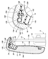
- a headrest 12 is provided on the upper part of the seat back 3. As shown in FIG. 2, the headrest 12 has a pillar member 13, a base member 14, a connecting member 15 that connects the base member 14 to the pillar member 13, and a pad 16 supported by the base member 14. In this embodiment, the headrest 12 has a skin material 17 that covers the pad 16.
- the pillar member 13 has left and right vertical axis portions 13A extending upward from the upper part of the seat back 3 and upper ends of the left and right vertical axis portions 13A. It has a left and right first horizontal shaft portion 13C extending forward via a curved portion 13B, and a second horizontal shaft portion 13D extending left and right and connected to each of the front portions of the first horizontal shaft portion 13C.
- the left and right vertical axis portions 13A extend in parallel in a substantially straight line.
- the left and right first horizontal axis portions 13C are substantially orthogonal to the plane including the left and right vertical axis portions 13A, and extend in the same direction with each other.
- the left and right vertical axis portions 13A, the left and right first horizontal axis portions 13C, and the second horizontal axis portion 13D are formed by bending a metal rod having a circular cross section.
- the seat back 3 is provided with left and right pillar support portions 19 that receive the lower portions of the left and right vertical axis portions 13A.
- the left and right pillar support portions 19 are tubular portions that receive the left and right vertical axis portions 13A, respectively, and support the vertical axis portion 13A at an arbitrary position by frictional force.
- the second horizontal shaft portion 13D and the left and right first horizontal shaft portions 13C are located on the front side of the seat back 3, that is, on the occupant side with respect to the upper end of the vertical axis portion 13A. To position.
- the base member 14 has a base vertical portion 14A extending vertically and a base upper portion 14B extending rearward from the upper end of the base vertical portion 14A.
- Left and right first holes 21 penetrating vertically are formed in the upper portion 14B of the base, respectively.
- the left and right curved portions 13B or the left and right vertical axis portions 13A pass through the left and right first holes 21, and the left and right first horizontal axis portions 13C are arranged above the base upper portion 14B.
- the base vertical portion 14A is arranged in front of the left and right vertical vertical portions 13A.
- the coupling member 15 rotatably couples the base upper portion 14B to the second horizontal shaft portion 13D.
- the coupling member 15 extends from one side edge of the groove-shaped locking portion 15A that rotatably receives the second horizontal shaft portion 13D and the locking portion 15A, and is fastened to the base upper portion 14B by the fastening member 22. It has one fastening portion 15B.
- the coupling member 15 has a second fastening portion 15C extending from the other side edge of the locking portion 15A and fastened to the base upper portion 14B by the fastening member 22.
- the locking portion 15A has a C-shaped cross section and extends in the left-right direction along the outer circumference of the second horizontal shaft portion 13D.
- the locking portion 15A is open toward the rear.
- the first fastening portion 15B extends rearward from the upper side edge defining the opening of the locking portion 15A and is arranged behind the second horizontal shaft portion 13D.
- the second fastening portion 15C extends rearward from the lower side edge defining the opening of the locking portion 15A and is arranged behind the second horizontal shaft portion 13D.
- the first fastening portion 15B and the second fastening portion 15C are each formed on a flat plate, and the surfaces thereof face up and down.
- the locking portion 15A, the first fastening portion 15B, and the second fastening portion 15C may be formed by bending a single sheet metal.
- the base member 14 has a base hole 24 penetrating the base member 14 at the boundary between the base upper portion 14B and the base vertical portion 14A.
- the base hole 24 penetrates the base member 14 in the front-rear direction and has a width in the left-right direction.
- the upper edge of the base hole 24 is connected to the lower surface of the base upper portion 14B.
- the second horizontal axis portion 13D is arranged at the boundary between the base upper portion 14B and the base vertical portion 14A. Specifically, the second horizontal shaft portion 13D is arranged in front of the front edge of the base upper portion 14B.
- the first fastening portion 15B is arranged along the upper surface of the base upper portion 14B.
- the second fastening portion 15C passes through the base hole 24 and is arranged along the lower surface of the base upper portion 14B. That is, the first fastening portion 15B and the second fastening portion 15C are arranged so as to sandwich the base upper portion 14B.
- the fastening member 22 has a bolt 22A that penetrates the first fastening portion 15B, the base upper portion 14B, and the second fastening portion 15C, and a nut 22B that is screwed into the bolt 22A.
- the nut 22B may be welded to the second fastening portion 15C. This makes it possible to facilitate the fastening work of the coupling member 15 to the base upper portion 14B by the bolt 22A.
- the distance between the upper side edge and the lower side edge of the locking portion 15A is set to be smaller than the diameter of the second horizontal shaft portion 13D. Further, the distance between the first fastening portion 15B and the second fastening portion 15C is set to be smaller than the diameter of the second horizontal shaft portion 13D. This makes it difficult for the second horizontal shaft portion 13D to come out of the opening of the locking portion 15A.
- the second horizontal shaft portion 13D is rotatably supported by the locking portion 15A. By applying a frictional force to the outer peripheral surface of the second horizontal shaft portion 13D by the inner peripheral surface of the locking portion 15A, the rotation angle of the second horizontal shaft portion 13D with respect to the locking portion 15A when a predetermined load is not applied. Is maintained.
- the locking portion 15A protrudes in the axial direction of the bolt 22A from the end of the bolt 22A of the fastening member 22.
- a head that engages with a tool is provided at the end of the bolt 22A.
- the locking portion 15A is arranged in a direction away from the upper surface of the base than the end portion of the bolt 22A. As a result, it is possible to prevent the end portion of the bolt 22A from hitting the occupant's head via the pad 16.
- the base vertical portion 14A has a first bulging portion 26 bulging in a direction away from the base upper portion 14B than the second horizontal shaft portion 13D at the upper portion thereof.
- the first bulging portion 26 extends in the left-right direction, and its upper edge is connected to the lower edge of the base hole 24.
- a flat end face is formed at the protruding end of the first bulging portion 26.
- the first bulging portion 26 is arranged between the left and right vertical axis portions 13A.
- the first bulging portion 26 can improve the rigidity of the base vertical portion 14A by introducing a three-dimensional shape into the base vertical portion 14A.
- a recess 26A for receiving a part of the coupling member 15 is formed on the second horizontal shaft portion 13D side of the first bulging portion 26, that is, on the upper edge portion.
- the base vertical portion 14A has at least one second bulging portion 27 that bulges forward and extends downward from the first bulging portion 26.
- the left and right second bulging portions 27 extend vertically at intervals from each other.
- the base vertical portion 14A has a third bulging portion 28 that bulges forward and extends along the edge of the base vertical portion 14A.
- the second bulging portion 27 and the third bulging portion 28 are connected to each other.
- a plurality of reinforcing ribs 29 extending in a direction orthogonal to the longitudinal direction are provided on the back surfaces of the second bulging portion 27 and the third bulging portion 28. Further, a plurality of reinforcing ribs 29 are also provided on the back surface of the first bulging portion 26.
- the second bulging portion 27 and the third bulging portion 28 can improve the rigidity of the base vertical portion 14A.
- the base upper portion 14B has left and right groove portions 31 that are recessed downward and extend in the front-rear direction.
- the left and right first horizontal shaft portions 13C can be arranged in the corresponding groove portions 31, and the amount of protrusion of the first horizontal shaft portion 13C with respect to the base upper portion 14B can be suppressed.
- the front ends of the left and right groove portions 31 are connected to the grooves formed between the first bulge portion 26 and the third bulge portion 28.
- each of the first holes 21 is formed at the rear end of the corresponding groove 31.
- the left and right first holes 21 are elongated holes extending in the front-rear direction, respectively, and at least one of the front end and the rear end of the first hole 21 is formed in a substantially triangular shape.
- the front end of each first hole 21 is formed in a substantially triangular shape.
- an edge wall portion 32 projecting upward is provided on the trailing edge of the base upper portion 14B.
- the edge wall portion 32 is curved forward toward the upper side.
- a plurality of reinforcing ribs 29 extending from the upper end of the edge wall portion 32 to the upper surface of the base upper portion 14B are provided.
- the pads 16 are a pad vertical portion 16A arranged on the front side of the base vertical portion 14A and a pad extending rearward from the upper end of the pad vertical portion 16A and arranged on the upper surface side of the base upper portion 14B. It has an upper portion 16B.
- the pad upper portion 16B covers the left and right first horizontal shaft portions 13C, the second horizontal shaft portion 13D, and the upper part of the coupling member 15.
- the lower surface of the pad upper portion 16B is in contact with the first fastening portion 15B between the locking portion 15A and the head of the bolt 22A.
- the height of the headrest 12 with respect to the seat back 3 can be changed by sliding the left and right vertical axis portions 13A with respect to the left and right pillar support portions 19.
- the height of the headrest 12 can be changed between the low position, which is the lowest position, and the high position, which is the highest position, with respect to the seat back 3.
- the rear surface of the base vertical portion 14A abuts on the front surface of the seat back 3
- the lower surface of the base upper portion 14B abuts on the upper end surface of the seat back 3, so that the base member with respect to the pillar member 13
- the rotation of 14 is restricted. As shown in FIG.
- the base member 14 when the headrest 12 is in a high position, the base member 14 can rotate about the second horizontal shaft portion 13D.
- the rotation range of the base member 14 with respect to the second horizontal shaft portion 13D is determined by the contact between the left and right vertical axis portions 13A and the front and rear ends of the left and right first holes 21.
- the second horizontal axis portion 13D is arranged in front of the vertical axis portion 13A by the first horizontal axis portion 13C. Therefore, the pillar member 13 can directly receive a part of the load from the front without going through the base member 14 and the coupling member 15. As a result, it is possible to reduce the load applied to the connecting member 15 that connects the second horizontal shaft portion 13D and the base member 14 in the headrest 12.
- the locking portion 15A opens rearward, and the first fastening portion 15B and the second fastening portion 15C are fastened to the base upper portion 14B behind the second horizontal shaft portion 13D. Therefore, when a load is applied to the base member 14 from the front, the locking portion 15A is maintained in a state of being caught by the second horizontal shaft portion 13D. As a result, it is possible to prevent the locking portion 15A from falling off or moving from the second horizontal shaft portion 13D. Further, since the coupling member 15 and the fastening member 22 are arranged behind the second horizontal shaft portion 13D, the coupling member 15 and the fastening member 22 are less likely to hit the occupant's head via the pad 16.
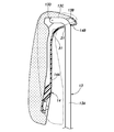
- the headrest 40 according to the second embodiment in which a part of the configuration of the headrest 40 according to the first embodiment is modified will be described with reference to FIGS. 7 and 8.
- the headrest 40 according to the second embodiment has different shapes of the pillar member 41, the base member 42, and the coupling member 43 as compared with the headrest 40 according to the first embodiment.
- the same components as those of the headrest 12 according to the first embodiment are designated by the same reference numerals and description thereof will be omitted.
- the pillar member 41 extends forward from the left and right vertical axis portions 41A extending upward from the upper portion of the seat back 3 and from the upper ends of the left and right vertical axis portions 41A via the curved portion 41B.
- the left and right first horizontal shaft portions 41C, the second horizontal shaft portion 41D extending left and right and connected to each of the front portions of the first horizontal shaft portion 41C, and the front of the second horizontal shaft portion 41D extending left and right to the left and right. It has a third horizontal shaft portion 41E coupled to each front end of the first horizontal shaft portion 41C of the above.
- the left and right vertical axis portions 41A extend in parallel in a substantially straight line.
- the left and right first horizontal axis portions 41C extend forward and downward so as to form an acute angle with the corresponding vertical axis portion 41A.
- the left and right vertical axis portions 41A, the left and right first horizontal axis portions 41C, and the third horizontal axis portion 41E are formed by bending a metal rod having a circular cross section.
- the second horizontal shaft portion 41D may be connected to the left and right first horizontal shaft portions 41C by welding or the like.
- the base member 42 has a base vertical portion 42A extending vertically and a base upper portion 42B extending rearward from the upper end of the base vertical portion 42A. At the boundary between the base vertical portion 42A and the base upper portion 42B, a curved surface portion 42C that smoothly connects the base vertical portion 42A and the base upper portion 42B is provided.
- a fastening seat 45 projecting forward and upward is provided at the center of the curved surface portion 42C in the left-right direction.
- the fastening seat 45 has a first fastening surface 45A facing forward and a second fastening surface 45B extending rearward from the upper end of the first fastening surface 45A and facing upward.
- a bearing groove 45C that is recessed rearward and extends to the left and right is provided.
- the cross section of the bearing groove 45C is formed in a semicircular shape.
- the upper part 42B of the base is formed with left and right first holes 21 penetrating vertically.
- the left and right curved portions 41B or the left and right vertical axis portions 41A pass through the left and right first holes 21, and the left and right first horizontal axis portions 41C are arranged above the base upper portion 42B.
- the base vertical portion 42A is arranged in front of the left and right vertical vertical portions 41A.
- the coupling member 43 rotatably couples the fastening seat 45 to the second horizontal shaft portion 41D.
- the coupling member 43 includes a groove-shaped locking portion 43A that rotatably receives the second horizontal shaft portion 41D, a first fastening portion 43B extending from one side edge of the locking portion 43A, and the other of the locking portion 43A. It has a second fastening portion 43C extending from the side edge of the.
- the locking portion 43A has a semicircular cross section and extends in the left-right direction along the outer circumference of the second horizontal shaft portion 41D.
- the locking portion 43A opens rearward.
- the first fastening portion 43B extends downward from the lower side edge defining the opening of the locking portion 43A.
- the second fastening portion 43C extends rearward from the upper side edge defining the opening of the locking portion 43A.
- the first fastening portion 43B is formed on a flat plate, and the surface faces the front and back.
- the second fastening portion 43C is formed on a flat plate, and its surface faces up and down.
- the locking portion 43A, the first fastening portion 43B, and the second fastening portion 43C may be formed by bending a single sheet metal.
- the rear portion of the second horizontal shaft portion 41D is received by the bearing groove 45C.
- the first fastening portion 43B is arranged along the first fastening surface 45A and is fastened by a fastening member 47 composed of bolts and nuts.
- the second fastening portion 43C is arranged along the second fastening surface 45B and is fastened by a fastening member 47 composed of bolts and nuts.
- the first fastening portion 43B is fastened to the first fastening surface 45A
- the second fastening portion 43C is fastened to the second fastening surface 45B, so that the second horizontal shaft portion 41D has the bearing groove 45C and the locking portion 43A. It is sandwiched between them.
- the second horizontal shaft portion 41D is rotatably supported between the bearing groove 45C and the locking portion 43A.
- the coupling member 43 sandwiches the second horizontal shaft portion 41D with the base member 42, and generates a frictional force with respect to the rotation of the second horizontal shaft portion 41D.
- the rotation angle of 41D is maintained.
- the angle formed by the first fastening portion 43B and the second fastening portion 43C is, for example, preferably 90 degrees or more and 135 degrees.
- the third horizontal shaft portion 41E is arranged forward and downward with respect to the second horizontal shaft portion 41D, and is arranged in front of the base vertical shaft portion 42A.
- the lower edge of the third horizontal shaft portion 41E may be arranged below the lower edge of the second fastening portion 43C.
- a first edge wall 51 projecting forward is provided on the lower edge and the left and right side edges of the base vertical portion 42A.
- a second edge wall 52 that projects upward is provided on the trailing edge and the left and right side edges of the base upper portion 42B.
- the first edge wall 51 and the second edge wall 52 are connected to each other and are formed in an annular shape.
- a first reinforcing structure 53 is provided on the front surface of the base vertical portion 42A in a portion between the left and right vertical vertical portions 41A when viewed from the front.
- the first reinforcing structure 53 is formed by a plurality of ribs protruding forward, and is formed in a honeycomb shape.
- the first reinforcing structure 53 is connected to the first edge wall 51 by a second reinforcing structure 54 provided on the front surface of the base vertical portion 42A.
- the second reinforcing structure 54 may be a plurality of ribs extending left and right on the front surface of the base vertical portion 42A.
- the base upper portion 42B may be provided with a plurality of reinforcing ribs 55 extending from the second edge wall 52 to the upper surface of the base upper portion 42B.
- the pad 16 has a pad vertical portion 16A arranged on the front surface side of the base vertical portion 42A, and a pad upper portion 16B extending rearward from the upper end of the pad vertical portion 16A and arranged on the upper surface side of the base upper portion 42B.
- the pad 16 covers the left and right first horizontal shaft portions 41C, the second horizontal shaft portion 41D, the third horizontal shaft portion 41E, and the coupling member 43.
- the base member 42 can rotate around the second horizontal shaft portion 41D.
- the portion of the left and right first horizontal shaft portions 41C on the front side of the second horizontal shaft portion 41D or the third horizontal shaft portion 41E is the base vertical portion 42A. It is regulated by contacting the front surface.
- the rotation of the base member 42 in the other direction with respect to the second horizontal shaft portion 41D is restricted by the portion of the left and right first horizontal shaft portions 41C behind the second horizontal shaft portion 41D abutting on the upper surface of the base upper portion 42B. Will be done.
- the floor 9 is provided with a plurality of strikers 11, and the sheet 1 is provided with a plurality of coupling devices 8.
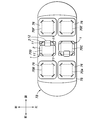
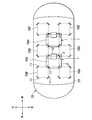
- the sheet 1 has four coupling devices 8.
- the coupling device 8 is provided on the front left portion, the front right portion, the rear left portion, and the rear right portion of the lower portion of the seat cushion 2.
- the four coupling devices 8 are preferably arranged at the vertices of a regular quadrangle when viewed from above.
- Each coupling device 8 has the same configuration. As shown in FIG. 9, the coupling device 8 has a base plate 61 extending downward from the seat cushion 2. A slot 62 capable of receiving the striker 11 is formed at the lower end of the base plate 61. The slot 62 is a groove portion recessed upward from the lower end of the base plate 61, and penetrates the base plate 61 in the horizontal direction. A latch 63 is rotatably provided on the base plate 61. The latch 63 is located in the slot 62 and rotates between a lock position for locking the striker 11 and a release position for retracting from the slot 62 and releasing the striker 11. The latch 63 may be rotated by the control cable 64 according to the operation of the user.
- the base plate 61 is provided with a latch 63, a ratchet 65, and an open lever 66. Further, the latch 63 is provided with an operating lever 67.
- the latch 63 is rotatably supported by the base plate 61 by the latch shaft 63A.
- the latch shaft 63A extends parallel to the extending direction of the slot 62.
- the position of the latch shaft 63A is behind the bottom of the slot 62.
- the latch 63 has a first hook portion 63B, a second hook portion 63C, a third hook portion 63D, a striker receiving groove 63E, and a lock groove 63F.
- a striker receiving groove 63E is formed between the first hook portion 63B and the second hook portion 63C, a second hook portion 63C is formed, and a lock groove 63F is formed between the second hook portion 63C and the third hook portion 63D. Is formed.
- the ratchet 65 is rotatably supported by the base plate 61 by the ratchet shaft 65A.
- the ratchet shaft 65A is arranged parallel to the latch shaft 63A.
- the ratchet shaft 65A is arranged obliquely upward and forward at the bottom of the slot 62.
- the ratchet 65 has a locking arm 65B and an operating arm 65C extending radially outward from the ratchet shaft 65A.
- the operating arm 65C is provided with an engaging pin 65D.
- the engagement pin 65D extends parallel to the ratchet shaft 65A.
- the locking arm 65B is provided with a cam follower 65E, which is a pin protruding in parallel with the ratchet shaft 65A.
- the open lever 66 is rotatably supported by the base plate 61 by the lever shaft 66A.
- the lever shaft 66A is provided in parallel with the latch shaft 63A.
- the lever shaft 66A is arranged above the ratchet shaft 65A.
- the open lever 66 has an engaging groove 66B on the outer periphery that receives the engaging pin 65D of the ratchet 65. By engaging the engaging pin 65D and the engaging groove 66B, the ratchet 65 rotates according to the rotation of the open lever 66.
- One end of the control cable 64 is connected to the outer peripheral portion of the open lever 66.
- the other end of the control cable 64 is connected to an operating lever or actuator (not shown).
- the open lever 66 rotates according to the operation of the control cable 64, and the ratchet 65 rotates.
- the operating lever 67 is rotatably supported by the latch 63 by the connecting shaft 67A.
- the connecting shaft 67A is arranged in parallel with the latch shaft 63A.
- the connecting shaft 67A is arranged on the third hook portion 63D side with respect to the latch shaft 63A.
- the operating lever 67 has an inscribed cam 67B, a spring locking portion 67C, a sliding contact surface 67D, and a contact portion 67E.
- the contact portion 67E is in the circumferential direction about the connecting shaft 67A and projects toward the ratchet shaft 65A side.
- the sliding contact surface 67D extends from the contact portion 67E in a circumferential direction centered on the connecting shaft 67A and in a direction opposite to the ratchet shaft 65A side.
- the sliding contact surface 67D is formed in a substantially arc shape centered on the connecting shaft 67A.
- the inscribed cam 67B is provided between the sliding contact surface 67D and the connecting shaft 67A.
- the inscribed cam 67B is a hole formed so as to penetrate from one side surface of the operating lever 67 to the opposite surface.
- a cam follower 65E is arranged in the inscribed cam 67B.
- the spring locking portion 67C is provided on the side opposite to the contact portion 67E side of the sliding contact surface 67D in the circumferential direction centered on the connecting shaft 67A, and protrudes outward in the radial direction centered on the connecting shaft 67A. ..
- the spring locking portion 67C and the engaging pin 65D of the ratchet 65 are connected by a tension spring 69.
- the tension spring 69 rotationally urges the actuating lever 67 in the direction in which the abutting portion 67E approaches the ratchet shaft 65A, and the ratchet 65 in the rotational direction in which the locking arm 65B approaches the latch 63.
- the latch 63 has a lock position in which the first hook portion 63B and the second hook portion 63C both enter the slot 62 and extend so as to cross the slot 62, and the first hook portion 63B retracts out of the slot 62 and is second.
- the hook portion 63C is inclined and rotates with the release position located in the slot 62.
- the ratchet 65 is urged by the tension spring 69 and the locking arm 65B is maintained in a state of being pushed into the lock groove 63F of the latch 63. As a result, the latch 63 is maintained in the locked position. At this time, the operating arm 65C is in sliding contact with the ratchet shaft 65A at the sliding contact portion.
- the open lever 66 rotates, the ratchet 65 rotates, and the locking arm 65B disengages from the lock groove 63F.
- the urging force of the tension spring 69 causes the entire operating lever 67 to move to the ratchet 65 side.
- the connecting shaft 67A moves to the ratchet 65 side, and the latch 63 rotates from the locked position to the released position.
- the ratchet 65 is rotated toward the latch 63 by the urging force of the tension spring 69, and the locking arm 65B urges the latch 63 toward the release position. In this way, when the latch 63 is in the release position, the latch 63 is maintained in the release position even if tension is not applied to the control cable 64.
- Each coupling device 8 passes through substantially the center of the seat cushion 2 and is arranged at a distance of 90 degrees from each other with the cushion center axis X1 extending in the vertical direction as the center.
- Each coupling device 8 is arranged on the seat cushion 2 so that the distance between the slot 62 of each engaging device and the cushion center axis X1 is equal to each other. Further, each coupling device 8 is arranged on the seat cushion 2 so that the orientation of each coupling device 8 is rotationally symmetric with respect to the cushion central axis X1.
- the base plate 61 is arranged so as to be inclined inward to the left and right toward the rear.
- the base plate 61 is arranged so as to be inclined outward to the left and right toward the rear.
- the slot 62 of each coupling device 8 extends in the radial direction about the central axis of the seat cushion 2. In the present embodiment, the slot 62 of each coupling device 8 is inclined by 45 degrees with respect to the front-rear direction.
- the striker 11 has a pair of pillars 11A protruding vertically upward from the floor 9 at intervals from each other, and a beam 11B connecting the upper ends of the pillars 11A to each other.
- the mounting area 70 is formed in a square shape, with front and rear edges extending left and right, and left and right edges extending back and forth.
- the four strikers 11 are arranged in the front left portion, the front right portion, the rear left portion, and the rear right portion of the mounting area 70.
- Each striker 11 passes through substantially the center of the mounting area 70 and is arranged at a distance of 90 degrees from each other with the mounting area center axis X2 extending in the vertical direction as the center.
- the strikers 11 are arranged on the floor 9 so that the distances between the strikers 11 and the mounting area center axis X2 are equal to each other.
- the distance between each striker 11 and the mounting area center axis X2 is set to be equal to the distance between the slot 62 of each coupling device 8 and the cushion center axis X1.
- each striker 11 is arranged on the floor 9 so that the orientation of each striker 11 is rotationally symmetric with respect to the mounting area center axis X2.
- the strikers 11 provided on the front left portion and the front right portion of the mounting area 70 are arranged so that the beam portion 11B is inclined outward to the left and right toward the rear. Further, in the striker 11 provided in the rear left portion and the rear right portion of the mounting area 70, the beam portion 11B is arranged so as to be inclined inward to the left and right toward the rear.
- the beam portion 11B of each striker 11 extends in the tangential direction centered on the mounting area center axis X2.
- the sheet 1 is arranged in the mounting area 70, and the four coupling devices 8 of the sheet 1 are detachably coupled to the four strikers 11 of the mounting area 70.
- the cushion center axis X1 is arranged so as to coincide with the mounting area center axis X2.
- the coupling device 8 on the rear left portion of the seat cushion 2 and the striker 11 on the rear left portion of the seat 1 region and the coupling device 8 on the rear right portion of the seat cushion 2 and the rear right portion of the seat 1 region.
- the seat 1 faces forward with respect to the vehicle 72.
- the coupling device 8 on the front left portion of the seat cushion 2 and the striker 11 on the rear left portion of the seat 1 region are coupled, and the coupling device 8 on the front right portion of the seat cushion 2 and the striker 11 on the front left portion of the seat 1 region are coupled.
- the coupling device 8 on the rear left portion of the seat cushion 2 and the striker 11 on the rear right portion of the seat 1 region and the coupling device 8 on the rear right portion of the seat cushion 2 and the front right portion of the seat 1 region.
- the seat 1 faces to the left with respect to the vehicle 72.
- the sheet 1 is restricted from moving in the horizontal direction and the vertical direction with respect to the floor 9.
- a plurality of mounting areas 70A to 70F are provided on the floor 9.
- the floor 9 of the passenger compartment 75 may be provided with six mounting areas 70A to 70F: front row left side, front row right side, middle row left side, middle row right side, rear row left side, and rear row right side.
- the above-mentioned sheet 1 is detachably attached to some of the attachment areas 70A to 70F.
- the orientation of the seat 1 mounted on the plurality of mounting areas 70A to 70F can be selected from front, left, right, and rear.
- attachments 76 different from those of the seat 1 may be attached to the plurality of attachment areas 70A to 70F.
- the attachment 76 may be, for example, a table, a shelf, a storage box, or the like.
- a coupling device 8 that is detachably coupled to four strikers 11 in at least one mounting area 70A to 70F is provided.
- the coupling device 8 provided on the attachment 76 may have, for example, the same configuration as the coupling device 8 provided on the sheet 1.
- FIG. 10 shows the first layout of the passenger compartment 75.
- the seats 1 are mounted in all the mounting areas 70A to 70F, and each seat 1 faces forward.
- FIG. 11 shows the second layout of the passenger compartment 75.
- the seat 1 is mounted in the mounting area 70A on the left side of the front row so that the seat 1 faces left
- the seat 1 is mounted in the mounting area 70B on the right side of the front row so as to face right
- the seat 1 is mounted in the mounting area 70E on the left side of the back row.
- the seat 1 is mounted so as to face left
- the seat 1 is mounted so as to face right in the mounting area 70F on the right side of the rear row
- the attachments 76 are mounted in the mounting areas 70C and 70D on the left side of the middle row and the right side of the middle row.
- the attachment 76 may be a table, a shelf, or a storage box.
- the second layout can provide a private space for the occupants seated in each seat 1. Therefore, the second layout is suitable for ride-sharing vehicles.
- FIG. 12 shows the third layout of the passenger compartment 75.
- the seat 1 is mounted in the mounting area 70D on the right side of the middle row so that the seat 1 faces forward, and the seat 1 is mounted in the mounting area 70C on the left side of the middle row so that the seat 1 faces rearward.
- Attachments 76 are attached to the attachment areas 70A, 70B, 70E, and 70F on the left side and the right side of the rear row.
- the attachments 76 on the left side of the front row and the right side of the back row may be, for example, shelves or storage boxes, and the attachments 76 on the right side of the front row and the left side of the back row may be tables.
- two occupants can each use two attachments 76.
- FIG. 13 shows the fourth layout of the passenger compartment 75.
- the seat 1 is mounted in the mounting areas 70A and 70B on the left side of the front row and the right side of the front row so that the seat 1 faces the rear, and the seat 1 is mounted in the mounting areas 70E and 70F on the left side of the rear row and the right side of the rear row so as to face the front.
- the seat 1 or the attachment 76 is not attached to the attachment areas 70C and 70D on the left side of the middle row and the right side of the middle row.
- each occupant faces the center of the vehicle 72 and faces each other, which is suitable for conversations and meetings.
- FIG. 14 shows the fifth layout of the passenger compartment 75.
- the seat 1 is mounted in the mounting areas 70A, 70C, 70E on the left side of the front row, the left side of the middle row, and the left side of the rear row so that the seat 1 faces forward, and the mounting areas 70B on the right side of the front row, the right side of the middle row, and the right side of the rear row, Attachments 76 are attached to 70D and 70F.
- the attachment 76 extends back and forth from the mounting area 70B on the right side of the front row to the mounting area 70F on the right side of the rear row.
- the attachment 76 may have a coupling device 8 that couples to each of the strikers 11 of the mounting areas 70B, 70D, and 70F on the right side of the front row, the right side of the middle row, and the right side of the rear row.
- the attachment 76 may be, for example, a table, a shelf, or a storage box. In the fifth layout, a large attachment 76 can be used.
- FIG. 15 shows the sixth layout of the passenger compartment 75.
- the distance between the left side mounting areas 70A, 70C, 70E and the right side mounting areas 70B, 70D, 70F is set to be equal to the length of one side of each mounting area 70A to 70F. Further, the distance between the front row mounting areas 70A and 70B and the middle row mounting areas 70C and 70D, the distance between the middle row mounting areas 70C and 70D and the rear row mounting areas 70E and 70F, and the respective mounting areas 70A to 70F.
- the length of one side is set to be equal.
- the striker 11 on the rear right side of the mounting area 70A on the left side of the front row, the striker 11 on the rear left side of the mounting area 70B on the right side of the front row, and the striker 11 on the front right side of the mounting area 70C on the left side of the middle row are in the middle.
- the front left intermediate mounting area 70G is formed by the striker 11 on the front left side of the mounting area 70D on the right side of the row.
- the rear intermediate mounting area 70H is formed by the striker 11 on the front left side of the mounting area 70F on the right side.
- the seat 1 is attached to each of the front intermediate attachment area 70G and the rear intermediate attachment area 70H so as to face forward. Further, the seat 1 attached to the rear intermediate attachment area 70H may face rearward. In the sixth layout, the seat 1 can be arranged at the center of the vehicle 72 in the width direction.
- the user can select the position and orientation of the seat 1 with respect to the floor 9 of the vehicle 72.
- the user can arrange the attachment 76 on the floor 9 as needed.
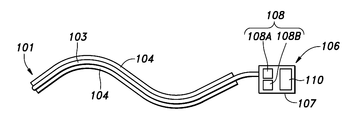
- the optical pipe 101 has a long light guide body 102 and a sheath 103 that covers the light guide body 102.
- the light guide 102 is an optical fiber and is made of a light-transmitting material such as polycarbonate.
- the sheath 103 is made of a transparent or translucent translucent material.
- the sheath 103 has a tab 104.
- the tab 104 is arranged between the pad 105 and the skin material 5, and may be sewn or adhered to the back surface of the skin material 5. It is preferable that the optical pipe 101 is provided at the seam of the skin material 5 and is exposed to the outside of the skin material 5. When reduced, the plurality of skin materials 5 are bonded to each other via the optical pipe 101.
- the optical pipe 101 is preferably arranged in the seat 1 at a position where it is difficult to contact the seated person or receive a load from the seated person.
- the optical pipe 101 may be arranged at a position away from the thighs, waist, and shoulders of the seated person.
- the optical pipe 101 provided on the seat cushion 2 may be provided along, for example, the front edge right portion, the right edge, the trailing edge, the left edge, and the front edge left portion of the seat surface (upper surface) 2A of the seat cushion 2. ..
- the optical pipe 101 provided on the seat back 3 may be provided along, for example, the right edge, the upper edge, and the left edge of the support surface (front surface) 3A of the seat back 3.
- the color of the light guide body 102 and the sheath 103 is preferably black, for example. As a result, when the optical pipe 101 does not emit light, the optical pipe 101 becomes inconspicuous. Any color can be adopted as the color of the light guide body 102 and the sheath 103.
- a light generator 106 is coupled to one end of the light pipe 101.
- the light generator 106 is provided in a housing 107 coupled to one end of an optical pipe 101, a light source 108 arranged in the housing 107 to irradiate one end of the light guide 102 with light, and a light source 108 provided in the housing 107. It has an optical control device 110 that controls a state.
- the light generator 106 may be arranged inside the seat cushion 2 and the seat back 3.
- the light source 108 is, for example, an LED, and may have a plurality of LEDs 108A and 108B having different emission colors.
- the light emitted from the light source 108 is input to the end portion of the light guide body 102 and leaks to the outside from the side surface of the light guide body 102 through the sheath 103. As a result, the optical pipe 101 is in a state of emitting light.
- the light control device 110 may change the emission color of the optical pipe 101 by changing the LEDs 108A and 108B used.
- the optical control device 110 may control the light source 108 based on a signal from another electric device provided on the sheet 1.
- the electric device includes, for example, a power receiving coil 112, a load sensor 113, a seat heater 114, a seat blower 115, a seat belt buckle sensor 116, and a biological information sensor 117.
- the power receiving coil 112 is connected to an in-vehicle battery, receives power by electromagnetic induction from a power transmission coil 121 provided in the mounting area 70 of the floor 9, and supplies power to the light generator 106 and other electric devices.
- the power receiving coil 112 starts receiving power from the power transmitting coil 121 when the sheet 1 is arranged in a predetermined mounting area.
- the optical control device 110 may cause the light source 108 to emit light when receiving electric power from the power receiving coil 112. Thereby, the user can recognize that the sheet 1 is arranged in the appropriate mounting area 70 based on the light emitting state of the optical pipe 101.
- the light control device 110 may first cause the first LED 108A having the first emission color to emit light, and after a lapse of a predetermined time, cause the second LED 108B having the second emission color to emit light in place of the first LED 108A. When the light source 108 is changed, the light control device 110 may gradually reduce the illuminance of the first LED 108A and gradually increase the illuminance of the second LED 108B.
- the optical control device 110 determines whether or not the sheet 1 is appropriately arranged in the mounting area 70 based on the voltage or current supplied from the power receiving coil 112, and the sheet 1 is appropriately arranged in the mounting area 70. If this is not the case, it is advisable to change the light emitting mode of the light source 108. For example, the optical control device 110 may determine that the sheet 1 is not properly arranged in the mounting area 70 when the voltage supplied from the power receiving coil 112 is less than a predetermined threshold value. The light control device 110 may blink the light source 108 or switch the emission color alternately when the sheet 1 is not properly arranged in the mounting area 70. Thereby, the user can visually recognize whether or not the sheet 1 is appropriately arranged in the mounting area 70 based on the light emitting state of the optical pipe 101.
- the load sensor 113 is provided on at least one of the upper surface of the seat cushion 2 and the front surface of the seat back 3, and detects an object placed on the seat 1.
- the load sensor 113 may be, for example, a membrane switch or a piezoelectric element.
- the load sensor 113 may be arranged between the pad of the seat cushion 2 and the skin material 5.
- the optical control device 110 may control the light source 108 based on the signal from the load sensor 113.
- the optical control device 110 may, for example, emit light from the light source 108 for a predetermined period after the membrane switch receives a load and is switched from off to on.
- the optical control device 110 may cause the light source 108 to emit light for a predetermined period after the load applied to the membrane switch disappears and the light source is switched from on to off. Further, the optical control device 110 may change the LEDs 108A and 108B to emit light when the state of the membrane switch changes between on and off. For example, when the membrane switch is off, the light control device 110 emits light from the first LED 108A, and when the membrane switch is switched from off to on, the light control device 110 gradually reduces the illuminance of the first LED 108A and the second LED 108B. It is advisable to gradually increase the illuminance.
- the commercial value of the seat 1 can be improved by changing the light emitting mode of the optical pipe 101 when the occupant sits on the seat 1.
- the seatbelt buckle sensor 116 detects the coupling state of the seatbelt buckle and tongue, and outputs an on signal when the buckle and tongue are coupled and an off signal when the buckle and tongue are separated. To do.
- the optical control device 110 may control the light emitting state of the light source 108 based on the signal from the seatbelt buckle sensor 116. As a result, the user can visually recognize that the seat belt is not fastened based on the light emitting state of the optical pipe 101.
- the sheet heater 114 has a sheet material formed of a non-woven fabric or the like, a heating wire provided on the sheet material, and a heater switch for connecting the heating wire and the power receiving coil 112.
- the heater switch cuts off the power supply from the power receiving coil 112 to the heating wire when it is in the off state, and enables the power supply from the power receiving coil 112 to the heating wire when it is in the on state.
- the optical control device 110 is connected to the heater switch and detects the state of the heater switch.
- the light control device 110 may control the light emitting state of the light source 108 based on the state of the heater switch.
- the optical control device 110 may cause the first LED 108A to emit light when the heater switch is on, and may cause the second LED 108B to emit light when the heater switch is off. Further, the optical control device 110 may gradually increase the illuminance of the second LED 108B while gradually decreasing the illuminance of the first LED 108A in accordance with the switching of the heater switch. Thereby, the user can visually recognize the operating state of the seat heater 114 based on the light emitting state of the optical pipe 101.
- the seat blower 115 has a blower provided inside at least one of the seat cushion 2 and the seat back 3, and a blower switch for connecting the blower and the power receiving coil 112.
- the blower switch cuts off the power supply from the power receiving coil 112 to the blower when it is in the off state, and enables the power supply from the power receiving coil 112 to the blower when it is in the on state.
- the blower is, for example, an axial fan, and blows air toward the upper surface of the seat cushion 2 or the front surface of the seat back 3.
- the optical control device 110 is connected to the blower switch and detects the state of the blower switch.
- the optical control device 110 may control the light emitting state of the light source 108 based on the state of the blower switch. For example, the optical control device 110 may cause the first LED 108A to emit light when the blower switch is on, and may cause the second LED 108B to emit light when the blower switch is off. Further, the optical control device 110 may gradually increase the illuminance of the second LED 108B while gradually decreasing the illuminance of the first LED 108A in accordance with the switching of the blower switch. As a result, the user can visually recognize the operating state of the sheet blower 115 based on the light emitting state of the optical pipe 101.
- the biometric information sensor 117 may include, for example, at least one of a pulse sensor, a temperature sensor, a respiration sensor, and a humidity sensor.
- the biological information sensor 117 is provided on at least one of the seat cushion 2 and the seat back 3, and acquires biological information including at least one of the pulse, body temperature, respiratory rate, and sweating state of the user seated on the seat 1.
- the biological information sensor 117 is connected to the optical control device 110 and outputs biological information to the optical control device 110.
- the light control device 110 controls the light emitting state of the light source 108 based on biological information.
- the optical control device 110 determines, for example, whether or not the pulse rate is within the predetermined determination range, and emits light from the light source 108 depending on whether the pulse rate is within the determination range or outside the determination range. Change the aspect. As a result, the seated person or the surrounding person of the seat 1 can visually recognize the seated person's state based on the light emitting state of the optical pipe 101.
- the optical control device 110 may be connected to the seat control device 119 provided on the seat 1 and control the light emitting state of the light source 108 based on the communication state between the seat control device 119 and the user terminal 123.
- the seat control device 119 is communicably connected to the user terminal 123 by, for example, short-range wireless communication or wired communication using a cable.
- the user terminal 123 may be a smartphone or the like.
- the seat control device 119 may control the drive, stop, and output amount of the seat heater 114, the seat blower 115, and the like based on the command signal from the user terminal 123.
- the seat control device 119 outputs a signal indicating a communication state with the user terminal 123 to the optical control device 110.
- the optical control device 110 detects the communication state between the seat control device 119 and the user terminal 123 based on the signal from the seat control device 119. For example, the optical control device 110 causes the first LED 108A to emit light when communication between the seat control device 119 and the user terminal 123 is established, and when the communication between the seat control device 119 and the user terminal 123 is disconnected, the first LED 108A is emitted. It is preferable to make 2LED108B emit light. As a result, the user can visually recognize the communication state between the seat control device 119 and the user terminal 123 based on the light emitting state of the optical pipe 101.
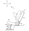
- the headrest 12 may be provided on the seat 130 as shown in.
- the seat 130 has a seat back 131 rotatably coupled to the floor 9 and a seat cushion 132 rotatably coupled to the seat back 131.
- a stay 134 that is rotatably connected to the floor 9 about an axis extending to the left and right is provided.
- the seat back 131 rotates between an upright position and a fall position that falls forward and extends substantially parallel to the floor 9.
- an arm 135 that is rotatably connected to the seat back 131 about an axis extending to the left and right is provided.
- the seat cushion 132 rotates between a position in which the seat cushion 132 is arranged substantially perpendicular to the seat back 131 and a tip-up position in which the upper surface (seat surface 2A) of the seat cushion 132 faces the front surface of the seat back 131. ..
- the seat back 131 can rotate to the overturned position.
- a rotatable leg member 137 is provided on the lower surface of the seat cushion 132.
- the leg member 137 has left and right vertical portions 137A extending in parallel with each other at intervals, and horizontal portions 137B connecting the corresponding ends of the left and right vertical portions 137A.
- the left and right vertical portions 137A and horizontal portions 137B may be formed, for example, by bending a continuous pipe material.
- the left and right vertical portions 137A members are rotatably coupled to the lower surface of the seat cushion 132 at the base end 137C, which is an end portion on the side opposite to the horizontal portion 137B side, about an axis extending to the left and right.
- the leg member 137 rotates between a use position that projects substantially perpendicular to the lower surface of the seat cushion 132 and a storage position along the lower surface of the seat cushion 132.
- the base ends 137C of the left and right vertical portions 137A are located above the horizontal portion 137B.
- the leg member 137 comes into contact with the floor 9 at the lateral portion 137B. As a result, the seat cushion 132 is supported by the floor 9 via the leg member 137.
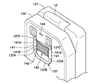
- Storage pockets 140 are attached to the left and right vertical portions 137A of the leg member 137.
- the storage pocket 140 has left and right joint portions 141 attached to the corresponding left and right vertical portions 137A, and bag portions 142 that extend left and right and are connected to the left and right joint portions 141 at both left and right ends.
- the left and right joint portions 141 and the bag portion 142 extend along the vertical portion 137A.
- the left and right joint portions 141 have a tubular shape and internally receive the vertical portion 137A.
- the left and right connecting portions 141 may have, for example, a sheet material 141A and a pair of connecting members 141B provided on the opposite edges of the sheet material 141A.
- the connecting member 141B may be, for example, a hook-and-loop fastener, a fastener, or a button. It is preferable to attach the connecting portion 141 to the vertical portion 137A by winding the sheet material 141A around the vertical portion 137A and then connecting the pair of connecting members 141B.
- the bag portion 142 opens on the base side of the vertical portion 137A and has a depth on the horizontal portion 137B side.
- the bag portion 142 is preferably formed of a sheet material such as a woven fabric or a mesh material. The user can use the storage pocket 140 as an accessory case. When the seat cushion 132 is in the used position and the leg member 137 is in the used position, the opening of the bag portion 142 faces vertically upward.
- the opening of the bag portion 142 faces vertically upward. Therefore, it is possible to prevent the article contained in the bag portion 142 from falling off from the bag portion 142.
- a lighting device 144 is provided between the left and right vertical portions 137A.
- the lighting device 144 may be, for example, an LED.
- the lighting device 144 may be provided on the lower surface of the seat cushion 132 between the bases of the left and right vertical portions 137A.
- the illuminator 144 illuminates the storage pocket 140. This makes it easier for the user to check the contents of the storage pocket 140.
- the headrest 12 may be provided on the bench seat 150 as shown in FIG.
- the bench seat 150 has a seat cushion 151 coupled to the floor 9 and a seat back 152 extending upward from the rear of the seat cushion 151.
- An armrest accommodating recess 153 recessed rearward is provided at the center of the seat back 152 in the left-right direction.
- the armrest 155 is rotatably supported at the lower part of the left and right wall portions defining the armrest accommodating recess 153.
- the armrest 155 rotates between a storage position accommodated in the armrest accommodating recess 153 and a use position protruding forward from the armrest accommodating recess 153.
- a connector module 157 is provided on the bottom surface of the armrest accommodating recess 153.
- the connector module 157 is arranged on the bottom surface of the armrest accommodating recess 153 above the upper surface of the armrest 155 located at the used position.
- the connector module 157 has at least one power supply port 157B provided in the main body 157A.
- the power port 157B may be, for example, a USB port.
- the connector module 157 may have a lighting device 157C in the main body 157A.
- the lighting device 157C may be, for example, an LED.
- the power port 157B and the lighting device 157C are connected to the vehicle-mounted battery.
- the connector module 157 may be provided with a lid 157D that covers the power supply port 157B and the lighting device 157C so as to be openable and closable.
- the lid 157B may be connected to the main body 157A by a hinge or the like.
- the illuminator 157C may be configured to emit light only when the lid 157D is open. For example, when the lid 157D is in the closed position, the power supply to the lighting device 157C may be cut off by pressing the switch 157E which cuts off the power supply to the lighting device 157C.
Landscapes
- Engineering & Computer Science (AREA)
- Aviation & Aerospace Engineering (AREA)
- Transportation (AREA)
- Mechanical Engineering (AREA)
- Seats For Vehicles (AREA)
- Chair Legs, Seat Parts, And Backrests (AREA)
Priority Applications (4)
| Application Number | Priority Date | Filing Date | Title |
|---|---|---|---|
| US17/761,922 US11890979B2 (en) | 2019-09-20 | 2020-09-07 | Headrest |
| JP2021546619A JP7553828B2 (ja) | 2019-09-20 | 2020-09-07 | ヘッドレスト |
| CN202080066043.3A CN114423645B (zh) | 2019-09-20 | 2020-09-07 | 头枕 |
| JP2024147154A JP2024163136A (ja) | 2019-09-20 | 2024-08-29 | 取付構造および車両 |
Applications Claiming Priority (8)
| Application Number | Priority Date | Filing Date | Title |
|---|---|---|---|
| US201962903418P | 2019-09-20 | 2019-09-20 | |
| US62/903,418 | 2019-09-20 | ||
| US201962914834P | 2019-10-14 | 2019-10-14 | |
| US201962914841P | 2019-10-14 | 2019-10-14 | |
| US62/914,841 | 2019-10-14 | ||
| US62/914,834 | 2019-10-14 | ||
| US201962942431P | 2019-12-02 | 2019-12-02 | |
| US62/942,431 | 2019-12-02 |
Publications (1)
| Publication Number | Publication Date |
|---|---|
| WO2021054184A1 true WO2021054184A1 (ja) | 2021-03-25 |
Family
ID=74884506
Family Applications (1)
| Application Number | Title | Priority Date | Filing Date |
|---|---|---|---|
| PCT/JP2020/033829 Ceased WO2021054184A1 (ja) | 2019-09-20 | 2020-09-07 | ヘッドレスト |
Country Status (4)
| Country | Link |
|---|---|
| US (1) | US11890979B2 (https=) |
| JP (2) | JP7553828B2 (https=) |
| CN (1) | CN114423645B (https=) |
| WO (1) | WO2021054184A1 (https=) |
Families Citing this family (2)
| Publication number | Priority date | Publication date | Assignee | Title |
|---|---|---|---|---|
| US12011097B2 (en) * | 2020-09-29 | 2024-06-18 | Lear Corporation | Seat assembly having an adjustable head restraint |
| WO2025184225A1 (en) * | 2024-02-27 | 2025-09-04 | Yanfeng International Automotive Technology Co. Ltd. | Component for vehicle interior |
Citations (7)
| Publication number | Priority date | Publication date | Assignee | Title |
|---|---|---|---|---|
| JPH0222151U (https=) * | 1988-07-28 | 1990-02-14 | ||
| JPH0645552U (ja) * | 1991-03-08 | 1994-06-21 | スズキ株式会社 | ヘッドレスト |
| JPH07231824A (ja) * | 1994-02-23 | 1995-09-05 | Aisin Seiki Co Ltd | ヘツドレスト装置 |
| JPH09149837A (ja) * | 1995-11-30 | 1997-06-10 | Aisin Seiki Co Ltd | ヘッドレスト装置 |
| JP2005287967A (ja) * | 2004-04-02 | 2005-10-20 | Honda Motor Co Ltd | 前枕部の揺動可能なヘッドレスト |
| US8322790B2 (en) * | 2009-04-08 | 2012-12-04 | Lear Corporation | Seat assembly having a multi-position head restraint assembly |
| JP2018086873A (ja) * | 2016-11-28 | 2018-06-07 | トヨタ紡織株式会社 | ヘッドレスト及び乗物用シート |
Family Cites Families (15)
| Publication number | Priority date | Publication date | Assignee | Title |
|---|---|---|---|---|
| US4991907A (en) * | 1988-07-28 | 1991-02-12 | Ikeda Bussan Co., Ltd. | Automobile seat head rest device |
| JP2865155B2 (ja) | 1992-07-23 | 1999-03-08 | 日本電気株式会社 | 半導体装置およびその製造方法 |
| JPH11222056A (ja) * | 1998-02-06 | 1999-08-17 | Aichi Mach Ind Co Ltd | 着脱式シートの取付方式 |
| JP2951953B1 (ja) * | 1998-09-11 | 1999-09-20 | 難波プレス工業株式会社 | ヘッドレスト及びその製造方法 |
| JP5422851B2 (ja) * | 2009-05-13 | 2014-02-19 | ジョンソン コントロールズ テクノロジー カンパニー | 回転式ヘッドレスト |
| DE102010001598B3 (de) * | 2010-02-04 | 2011-07-28 | Lear Corp., Mich. | Sitzbaugruppe mit einer beweglichen Kopfstützen-Baugruppe |
| DE102010045128B4 (de) * | 2010-09-11 | 2016-11-10 | Johnson Controls Gmbh | Kopfstütze für einen Fahrzeugsitz |
| DE102011100341B4 (de) * | 2011-04-14 | 2016-12-01 | Grammer Aktiengesellschaft | Kopfstütze für Fahrzeugsitze und Verfahren zur Herstellung einer Kopfstütze für Fahrzeugsitze |
| US20130285431A1 (en) * | 2012-04-26 | 2013-10-31 | Martur Sunger Ve Koltuk Tesisleri Ticaret Ve Sanayi Anonim Sirketi | Rear headrest mechanism used in the passenger seats of motor vehicles |
| US8991927B2 (en) * | 2012-11-26 | 2015-03-31 | World Class Plastics, Inc. | Holder for headrest |
| JP5557946B1 (ja) * | 2013-05-15 | 2014-07-23 | 日本発條株式会社 | ヘッドレスト構造及びヘッドレスト装置 |
| JP6059086B2 (ja) * | 2013-05-31 | 2017-01-11 | 株式会社タチエス | ヘッドレスト |
| US9511696B2 (en) * | 2015-05-06 | 2016-12-06 | Daimay North America Automotive, Inc. | Rotatable headrest assembly |
| US9731637B2 (en) * | 2015-08-17 | 2017-08-15 | Lear Corporation | Seat assembly having a headrest and method of assembly |
| JP6686698B2 (ja) * | 2016-05-24 | 2020-04-22 | トヨタ紡織株式会社 | 乗物用シート |
-
2020
- 2020-09-07 WO PCT/JP2020/033829 patent/WO2021054184A1/ja not_active Ceased
- 2020-09-07 US US17/761,922 patent/US11890979B2/en active Active
- 2020-09-07 JP JP2021546619A patent/JP7553828B2/ja active Active
- 2020-09-07 CN CN202080066043.3A patent/CN114423645B/zh active Active
-
2024
- 2024-08-29 JP JP2024147154A patent/JP2024163136A/ja active Pending
Patent Citations (7)
| Publication number | Priority date | Publication date | Assignee | Title |
|---|---|---|---|---|
| JPH0222151U (https=) * | 1988-07-28 | 1990-02-14 | ||
| JPH0645552U (ja) * | 1991-03-08 | 1994-06-21 | スズキ株式会社 | ヘッドレスト |
| JPH07231824A (ja) * | 1994-02-23 | 1995-09-05 | Aisin Seiki Co Ltd | ヘツドレスト装置 |
| JPH09149837A (ja) * | 1995-11-30 | 1997-06-10 | Aisin Seiki Co Ltd | ヘッドレスト装置 |
| JP2005287967A (ja) * | 2004-04-02 | 2005-10-20 | Honda Motor Co Ltd | 前枕部の揺動可能なヘッドレスト |
| US8322790B2 (en) * | 2009-04-08 | 2012-12-04 | Lear Corporation | Seat assembly having a multi-position head restraint assembly |
| JP2018086873A (ja) * | 2016-11-28 | 2018-06-07 | トヨタ紡織株式会社 | ヘッドレスト及び乗物用シート |
Also Published As
| Publication number | Publication date |
|---|---|
| JP7553828B2 (ja) | 2024-09-19 |
| CN114423645B (zh) | 2024-07-30 |
| CN114423645A (zh) | 2022-04-29 |
| US11890979B2 (en) | 2024-02-06 |
| JP2024163136A (ja) | 2024-11-21 |
| JPWO2021054184A1 (https=) | 2021-03-25 |
| US20220348123A1 (en) | 2022-11-03 |
Similar Documents
| Publication | Publication Date | Title |
|---|---|---|
| JP2024163136A (ja) | 取付構造および車両 | |
| US10414306B2 (en) | Seat apparatus | |
| JP5135857B2 (ja) | 車両用シート | |
| US20220031876A1 (en) | Vehicle seat with disinfecting light | |
| JP2009279999A (ja) | 車両室内の意匠用照明構造 | |
| KR20230053565A (ko) | 이동형 시트를 포함하는 차량 | |
| WO2023054404A1 (ja) | 乗り物用シート | |
| JP2012040110A (ja) | 椅子 | |
| JP4296889B2 (ja) | 車両用アームレスト | |
| JP5712370B2 (ja) | 椅子 | |
| JP5824491B2 (ja) | バックル装置の取付構造 | |
| JP7148781B2 (ja) | シートの光る領域とヒーター線との配置構造及び車両用シート | |
| JP2008221018A (ja) | 車両用シートカバー | |
| JP2017018165A (ja) | スライドファスナー付き表皮材およびその縫製方法 | |
| WO2019131201A1 (ja) | シートの光る領域とヒーター線との配置構造及び車両用シート | |
| JP4172480B2 (ja) | 車両用シートカバー | |
| WO2021235552A1 (ja) | 乗物用シート及び乗物用シートの製造方法 | |
| JP4032020B2 (ja) | 車両のシート構造 | |
| JP2022001487A (ja) | 乗り物用シート及び乗り物用ユニット | |
| JPH0239929U (https=) | ||
| JP4486868B2 (ja) | 車両のシート構造 | |
| US20170136927A1 (en) | Vehicle | |
| JPH0212963U (https=) | ||
| JP2021183480A (ja) | 乗物用シート及び乗物用シートの製造方法 | |
| JPH052131Y2 (https=) |
Legal Events
| Date | Code | Title | Description |
|---|---|---|---|
| 121 | Ep: the epo has been informed by wipo that ep was designated in this application |
Ref document number: 20865800 Country of ref document: EP Kind code of ref document: A1 |
|
| ENP | Entry into the national phase |
Ref document number: 2021546619 Country of ref document: JP Kind code of ref document: A |
|
| NENP | Non-entry into the national phase |
Ref country code: DE |
|
| 122 | Ep: pct application non-entry in european phase |
Ref document number: 20865800 Country of ref document: EP Kind code of ref document: A1 |