WO2021049178A1 - 非水電解質蓄電素子、及び蓄電装置 - Google Patents
非水電解質蓄電素子、及び蓄電装置 Download PDFInfo
- Publication number
- WO2021049178A1 WO2021049178A1 PCT/JP2020/028257 JP2020028257W WO2021049178A1 WO 2021049178 A1 WO2021049178 A1 WO 2021049178A1 JP 2020028257 W JP2020028257 W JP 2020028257W WO 2021049178 A1 WO2021049178 A1 WO 2021049178A1
- Authority
- WO
- WIPO (PCT)
- Prior art keywords
- aqueous electrolyte
- power storage
- negative electrode
- carbonate
- active material
- Prior art date
Links
- 239000011255 nonaqueous electrolyte Substances 0.000 title claims abstract description 158
- 238000003860 storage Methods 0.000 title claims abstract description 99
- 229910052744 lithium Inorganic materials 0.000 claims abstract description 63
- 150000005676 cyclic carbonates Chemical class 0.000 claims abstract description 36
- 150000001923 cyclic compounds Chemical class 0.000 claims abstract description 35
- 239000007773 negative electrode material Substances 0.000 claims abstract description 34
- 239000002904 solvent Substances 0.000 claims abstract description 16
- 150000005678 chain carbonates Chemical class 0.000 claims abstract description 12
- NINIDFKCEFEMDL-UHFFFAOYSA-N Sulfur Chemical compound [S] NINIDFKCEFEMDL-UHFFFAOYSA-N 0.000 claims description 35
- 229910052717 sulfur Inorganic materials 0.000 claims description 35
- 239000011593 sulfur Substances 0.000 claims description 35
- SBLRHMKNNHXPHG-UHFFFAOYSA-N 4-fluoro-1,3-dioxolan-2-one Chemical compound FC1COC(=O)O1 SBLRHMKNNHXPHG-UHFFFAOYSA-N 0.000 claims description 15
- 150000001875 compounds Chemical class 0.000 claims description 12
- 150000008053 sultones Chemical group 0.000 claims description 6
- 239000010410 layer Substances 0.000 description 42
- 239000000463 material Substances 0.000 description 37
- OKTJSMMVPCPJKN-UHFFFAOYSA-N Carbon Chemical compound [C] OKTJSMMVPCPJKN-UHFFFAOYSA-N 0.000 description 28
- 239000007774 positive electrode material Substances 0.000 description 26
- -1 lithium transition metal Chemical class 0.000 description 23
- 239000010408 film Substances 0.000 description 20
- 239000000654 additive Substances 0.000 description 19
- 238000007600 charging Methods 0.000 description 19
- 238000000354 decomposition reaction Methods 0.000 description 18
- 230000002829 reductive effect Effects 0.000 description 16
- 230000000694 effects Effects 0.000 description 14
- 238000012360 testing method Methods 0.000 description 14
- 239000003125 aqueous solvent Substances 0.000 description 13
- 230000000996 additive effect Effects 0.000 description 11
- 239000003792 electrolyte Chemical class 0.000 description 11
- 229910002804 graphite Inorganic materials 0.000 description 11
- 239000010439 graphite Substances 0.000 description 11
- PXHVJJICTQNCMI-UHFFFAOYSA-N Nickel Chemical compound [Ni] PXHVJJICTQNCMI-UHFFFAOYSA-N 0.000 description 10
- 230000000052 comparative effect Effects 0.000 description 10
- 150000003839 salts Chemical class 0.000 description 10
- 239000007789 gas Substances 0.000 description 9
- 239000006258 conductive agent Substances 0.000 description 8
- 238000000034 method Methods 0.000 description 8
- RYGMFSIKBFXOCR-UHFFFAOYSA-N Copper Chemical compound [Cu] RYGMFSIKBFXOCR-UHFFFAOYSA-N 0.000 description 7
- HBBGRARXTFLTSG-UHFFFAOYSA-N Lithium ion Chemical compound [Li+] HBBGRARXTFLTSG-UHFFFAOYSA-N 0.000 description 7
- 238000012790 confirmation Methods 0.000 description 7
- 238000007599 discharging Methods 0.000 description 7
- 239000011888 foil Substances 0.000 description 7
- 229910001416 lithium ion Inorganic materials 0.000 description 7
- 230000014759 maintenance of location Effects 0.000 description 7
- 229910052723 transition metal Inorganic materials 0.000 description 7
- QMMFVYPAHWMCMS-UHFFFAOYSA-N Dimethyl sulfide Chemical compound CSC QMMFVYPAHWMCMS-UHFFFAOYSA-N 0.000 description 6
- WHXSMMKQMYFTQS-UHFFFAOYSA-N Lithium Chemical compound [Li] WHXSMMKQMYFTQS-UHFFFAOYSA-N 0.000 description 6
- 229910052782 aluminium Inorganic materials 0.000 description 6
- XAGFODPZIPBFFR-UHFFFAOYSA-N aluminium Chemical compound [Al] XAGFODPZIPBFFR-UHFFFAOYSA-N 0.000 description 6
- 239000011230 binding agent Substances 0.000 description 6
- 239000003990 capacitor Substances 0.000 description 6
- 229910052799 carbon Inorganic materials 0.000 description 6
- 239000013078 crystal Substances 0.000 description 6
- 229910003002 lithium salt Inorganic materials 0.000 description 6
- 229910052751 metal Inorganic materials 0.000 description 6
- 239000002184 metal Substances 0.000 description 6
- 239000002905 metal composite material Substances 0.000 description 6
- 229920005989 resin Polymers 0.000 description 6
- 239000011347 resin Substances 0.000 description 6
- XLYOFNOQVPJJNP-UHFFFAOYSA-N water Substances O XLYOFNOQVPJJNP-UHFFFAOYSA-N 0.000 description 6
- VAYTZRYEBVHVLE-UHFFFAOYSA-N 1,3-dioxol-2-one Chemical compound O=C1OC=CO1 VAYTZRYEBVHVLE-UHFFFAOYSA-N 0.000 description 5
- 238000006243 chemical reaction Methods 0.000 description 5
- 239000011889 copper foil Substances 0.000 description 5
- JBTWLSYIZRCDFO-UHFFFAOYSA-N ethyl methyl carbonate Chemical compound CCOC(=O)OC JBTWLSYIZRCDFO-UHFFFAOYSA-N 0.000 description 5
- 159000000002 lithium salts Chemical class 0.000 description 5
- IGILRSKEFZLPKG-UHFFFAOYSA-M lithium;difluorophosphinate Chemical compound [Li+].[O-]P(F)(F)=O IGILRSKEFZLPKG-UHFFFAOYSA-M 0.000 description 5
- 238000004519 manufacturing process Methods 0.000 description 5
- 239000000203 mixture Substances 0.000 description 5
- KMTRUDSVKNLOMY-UHFFFAOYSA-N Ethylene carbonate Chemical class O=C1OCCO1 KMTRUDSVKNLOMY-UHFFFAOYSA-N 0.000 description 4
- 239000002033 PVDF binder Substances 0.000 description 4
- 239000004743 Polypropylene Substances 0.000 description 4
- 239000006230 acetylene black Substances 0.000 description 4
- 125000004432 carbon atom Chemical group C* 0.000 description 4
- 239000006229 carbon black Substances 0.000 description 4
- LJSQFQKUNVCTIA-UHFFFAOYSA-N diethyl sulfide Chemical compound CCSCC LJSQFQKUNVCTIA-UHFFFAOYSA-N 0.000 description 4
- 239000002003 electrode paste Substances 0.000 description 4
- 230000002401 inhibitory effect Effects 0.000 description 4
- 238000002347 injection Methods 0.000 description 4
- 239000007924 injection Substances 0.000 description 4
- 239000007788 liquid Substances 0.000 description 4
- 229920001155 polypropylene Polymers 0.000 description 4
- 229920002981 polyvinylidene fluoride Polymers 0.000 description 4
- ZPFAVCIQZKRBGF-UHFFFAOYSA-N 1,3,2-dioxathiolane 2,2-dioxide Chemical compound O=S1(=O)OCCO1 ZPFAVCIQZKRBGF-UHFFFAOYSA-N 0.000 description 3
- IFDLFCDWOFLKEB-UHFFFAOYSA-N 2-methylbutylbenzene Chemical compound CCC(C)CC1=CC=CC=C1 IFDLFCDWOFLKEB-UHFFFAOYSA-N 0.000 description 3
- 229910000838 Al alloy Inorganic materials 0.000 description 3
- 229910013870 LiPF 6 Inorganic materials 0.000 description 3
- 239000004698 Polyethylene Substances 0.000 description 3
- 239000002041 carbon nanotube Substances 0.000 description 3
- 229910021393 carbon nanotube Inorganic materials 0.000 description 3
- 239000003575 carbonaceous material Substances 0.000 description 3
- 238000010280 constant potential charging Methods 0.000 description 3
- 238000010277 constant-current charging Methods 0.000 description 3
- 239000000945 filler Substances 0.000 description 3
- 229910021389 graphene Inorganic materials 0.000 description 3
- 150000002430 hydrocarbons Chemical group 0.000 description 3
- 150000002739 metals Chemical class 0.000 description 3
- 239000003960 organic solvent Substances 0.000 description 3
- 238000006864 oxidative decomposition reaction Methods 0.000 description 3
- 239000002245 particle Substances 0.000 description 3
- 229920000447 polyanionic polymer Polymers 0.000 description 3
- 229920000573 polyethylene Polymers 0.000 description 3
- 238000002360 preparation method Methods 0.000 description 3
- RUOJZAUFBMNUDX-UHFFFAOYSA-N propylene carbonate Chemical class CC1COC(=O)O1 RUOJZAUFBMNUDX-UHFFFAOYSA-N 0.000 description 3
- 239000010935 stainless steel Substances 0.000 description 3
- 229910001220 stainless steel Inorganic materials 0.000 description 3
- 239000000126 substance Substances 0.000 description 3
- 150000003457 sulfones Chemical class 0.000 description 3
- 239000002562 thickening agent Substances 0.000 description 3
- 238000004804 winding Methods 0.000 description 3
- ZZXUZKXVROWEIF-UHFFFAOYSA-N 1,2-butylene carbonate Chemical compound CCC1COC(=O)O1 ZZXUZKXVROWEIF-UHFFFAOYSA-N 0.000 description 2
- BJWMSGRKJIOCNR-UHFFFAOYSA-N 4-ethenyl-1,3-dioxolan-2-one Chemical compound C=CC1COC(=O)O1 BJWMSGRKJIOCNR-UHFFFAOYSA-N 0.000 description 2
- VTYYLEPIZMXCLO-UHFFFAOYSA-L Calcium carbonate Chemical compound [Ca+2].[O-]C([O-])=O VTYYLEPIZMXCLO-UHFFFAOYSA-L 0.000 description 2
- 229920002134 Carboxymethyl cellulose Polymers 0.000 description 2
- 229910000881 Cu alloy Inorganic materials 0.000 description 2
- OIFBSDVPJOWBCH-UHFFFAOYSA-N Diethyl carbonate Chemical compound CCOC(=O)OCC OIFBSDVPJOWBCH-UHFFFAOYSA-N 0.000 description 2
- 229920002943 EPDM rubber Polymers 0.000 description 2
- 229910000733 Li alloy Inorganic materials 0.000 description 2
- SECXISVLQFMRJM-UHFFFAOYSA-N N-Methylpyrrolidone Chemical compound CN1CCCC1=O SECXISVLQFMRJM-UHFFFAOYSA-N 0.000 description 2
- 239000004642 Polyimide Substances 0.000 description 2
- VYPSYNLAJGMNEJ-UHFFFAOYSA-N Silicium dioxide Chemical compound O=[Si]=O VYPSYNLAJGMNEJ-UHFFFAOYSA-N 0.000 description 2
- LSNNMFCWUKXFEE-UHFFFAOYSA-N Sulfurous acid Chemical compound OS(O)=O LSNNMFCWUKXFEE-UHFFFAOYSA-N 0.000 description 2
- GWEVSGVZZGPLCZ-UHFFFAOYSA-N Titan oxide Chemical compound O=[Ti]=O GWEVSGVZZGPLCZ-UHFFFAOYSA-N 0.000 description 2
- 239000011149 active material Substances 0.000 description 2
- 125000000217 alkyl group Chemical group 0.000 description 2
- 229910045601 alloy Inorganic materials 0.000 description 2
- 239000000956 alloy Substances 0.000 description 2
- 125000004429 atom Chemical group 0.000 description 2
- QVQLCTNNEUAWMS-UHFFFAOYSA-N barium oxide Chemical compound [Ba]=O QVQLCTNNEUAWMS-UHFFFAOYSA-N 0.000 description 2
- TZCXTZWJZNENPQ-UHFFFAOYSA-L barium sulfate Chemical compound [Ba+2].[O-]S([O-])(=O)=O TZCXTZWJZNENPQ-UHFFFAOYSA-L 0.000 description 2
- 150000001786 chalcogen compounds Chemical class 0.000 description 2
- 238000004891 communication Methods 0.000 description 2
- 239000000805 composite resin Substances 0.000 description 2
- 229910052802 copper Inorganic materials 0.000 description 2
- 239000010949 copper Substances 0.000 description 2
- 210000001787 dendrite Anatomy 0.000 description 2
- QXYJCZRRLLQGCR-UHFFFAOYSA-N dioxomolybdenum Chemical compound O=[Mo]=O QXYJCZRRLLQGCR-UHFFFAOYSA-N 0.000 description 2
- HNPSIPDUKPIQMN-UHFFFAOYSA-N dioxosilane;oxo(oxoalumanyloxy)alumane Chemical compound O=[Si]=O.O=[Al]O[Al]=O HNPSIPDUKPIQMN-UHFFFAOYSA-N 0.000 description 2
- 239000002612 dispersion medium Substances 0.000 description 2
- 238000004090 dissolution Methods 0.000 description 2
- 229920001971 elastomer Polymers 0.000 description 2
- 239000008151 electrolyte solution Substances 0.000 description 2
- 150000002148 esters Chemical class 0.000 description 2
- 125000000524 functional group Chemical group 0.000 description 2
- 150000004676 glycans Chemical class 0.000 description 2
- 125000004435 hydrogen atom Chemical group [H]* 0.000 description 2
- 239000001989 lithium alloy Substances 0.000 description 2
- 238000005259 measurement Methods 0.000 description 2
- 125000002496 methyl group Chemical group [H]C([H])([H])* 0.000 description 2
- 229910052759 nickel Inorganic materials 0.000 description 2
- 239000004745 nonwoven fabric Substances 0.000 description 2
- 230000003647 oxidation Effects 0.000 description 2
- 238000007254 oxidation reaction Methods 0.000 description 2
- 229920001721 polyimide Polymers 0.000 description 2
- 229920000642 polymer Polymers 0.000 description 2
- 229920000098 polyolefin Polymers 0.000 description 2
- 229920001282 polysaccharide Polymers 0.000 description 2
- 239000005017 polysaccharide Substances 0.000 description 2
- 229920001343 polytetrafluoroethylene Polymers 0.000 description 2
- 239000004810 polytetrafluoroethylene Substances 0.000 description 2
- 238000001556 precipitation Methods 0.000 description 2
- 238000004080 punching Methods 0.000 description 2
- 230000009467 reduction Effects 0.000 description 2
- 238000007086 side reaction Methods 0.000 description 2
- 239000000243 solution Substances 0.000 description 2
- 229910052596 spinel Inorganic materials 0.000 description 2
- 239000011029 spinel Substances 0.000 description 2
- IATRAKWUXMZMIY-UHFFFAOYSA-N strontium oxide Chemical compound [O-2].[Sr+2] IATRAKWUXMZMIY-UHFFFAOYSA-N 0.000 description 2
- 229920003048 styrene butadiene rubber Polymers 0.000 description 2
- HXJUTPCZVOIRIF-UHFFFAOYSA-N sulfolane Chemical compound O=S1(=O)CCCC1 HXJUTPCZVOIRIF-UHFFFAOYSA-N 0.000 description 2
- OQYOVYWFXHQYOP-UHFFFAOYSA-N 1,3,2-dioxathiane 2,2-dioxide Chemical compound O=S1(=O)OCCCO1 OQYOVYWFXHQYOP-UHFFFAOYSA-N 0.000 description 1
- FSSPGSAQUIYDCN-UHFFFAOYSA-N 1,3-Propane sultone Chemical compound O=S1(=O)CCCO1 FSSPGSAQUIYDCN-UHFFFAOYSA-N 0.000 description 1
- NZPSDGIEKAQVEZ-UHFFFAOYSA-N 1,3-benzodioxol-2-one Chemical compound C1=CC=CC2=C1OC(=O)O2 NZPSDGIEKAQVEZ-UHFFFAOYSA-N 0.000 description 1
- VKSWWACDZPRJAP-UHFFFAOYSA-N 1,3-dioxepan-2-one Chemical class O=C1OCCCCO1 VKSWWACDZPRJAP-UHFFFAOYSA-N 0.000 description 1
- YBJCDTIWNDBNTM-UHFFFAOYSA-N 1-methylsulfonylethane Chemical compound CCS(C)(=O)=O YBJCDTIWNDBNTM-UHFFFAOYSA-N 0.000 description 1
- RDKKQZIFDSEMNU-UHFFFAOYSA-N 2-ethylsulfonylpropane Chemical compound CCS(=O)(=O)C(C)C RDKKQZIFDSEMNU-UHFFFAOYSA-N 0.000 description 1
- DSMUTQTWFHVVGQ-UHFFFAOYSA-N 4,5-difluoro-1,3-dioxolan-2-one Chemical compound FC1OC(=O)OC1F DSMUTQTWFHVVGQ-UHFFFAOYSA-N 0.000 description 1
- SROHGOJDCAODGI-UHFFFAOYSA-N 4,5-diphenyl-1,3-dioxol-2-one Chemical compound O1C(=O)OC(C=2C=CC=CC=2)=C1C1=CC=CC=C1 SROHGOJDCAODGI-UHFFFAOYSA-N 0.000 description 1
- OYOKPDLAMOMTEE-UHFFFAOYSA-N 4-chloro-1,3-dioxolan-2-one Chemical compound ClC1COC(=O)O1 OYOKPDLAMOMTEE-UHFFFAOYSA-N 0.000 description 1
- VMAJRFCXVOIAAS-UHFFFAOYSA-N 4-phenyl-1,3-dioxol-2-one Chemical compound O1C(=O)OC=C1C1=CC=CC=C1 VMAJRFCXVOIAAS-UHFFFAOYSA-N 0.000 description 1
- ZKOGUIGAVNCCKH-UHFFFAOYSA-N 4-phenyl-1,3-dioxolan-2-one Chemical compound O1C(=O)OCC1C1=CC=CC=C1 ZKOGUIGAVNCCKH-UHFFFAOYSA-N 0.000 description 1
- 239000005995 Aluminium silicate Substances 0.000 description 1
- XMWRBQBLMFGWIX-UHFFFAOYSA-N C60 fullerene Chemical class C12=C3C(C4=C56)=C7C8=C5C5=C9C%10=C6C6=C4C1=C1C4=C6C6=C%10C%10=C9C9=C%11C5=C8C5=C8C7=C3C3=C7C2=C1C1=C2C4=C6C4=C%10C6=C9C9=C%11C5=C5C8=C3C3=C7C1=C1C2=C4C6=C2C9=C5C3=C12 XMWRBQBLMFGWIX-UHFFFAOYSA-N 0.000 description 1
- 229920000049 Carbon (fiber) Polymers 0.000 description 1
- 229920008712 Copo Polymers 0.000 description 1
- 229910013063 LiBF 4 Inorganic materials 0.000 description 1
- 229910013684 LiClO 4 Inorganic materials 0.000 description 1
- 229910011281 LiCoPO 4 Inorganic materials 0.000 description 1
- 229910010707 LiFePO 4 Inorganic materials 0.000 description 1
- 229910013131 LiN Inorganic materials 0.000 description 1
- 229910013528 LiN(SO2 CF3)2 Inorganic materials 0.000 description 1
- 229910013392 LiN(SO2CF3)(SO2C4F9) Inorganic materials 0.000 description 1
- 229910013086 LiNiPO Inorganic materials 0.000 description 1
- 229910012258 LiPO Inorganic materials 0.000 description 1
- 229910012424 LiSO 3 Inorganic materials 0.000 description 1
- 229910001228 Li[Ni1/3Co1/3Mn1/3]O2 (NCM 111) Inorganic materials 0.000 description 1
- 241000156302 Porcine hemagglutinating encephalomyelitis virus Species 0.000 description 1
- 229910052581 Si3N4 Inorganic materials 0.000 description 1
- 229910000831 Steel Inorganic materials 0.000 description 1
- 239000002174 Styrene-butadiene Substances 0.000 description 1
- UCKMPCXJQFINFW-UHFFFAOYSA-N Sulphide Chemical compound [S-2] UCKMPCXJQFINFW-UHFFFAOYSA-N 0.000 description 1
- RTAQQCXQSZGOHL-UHFFFAOYSA-N Titanium Chemical compound [Ti] RTAQQCXQSZGOHL-UHFFFAOYSA-N 0.000 description 1
- 229910021536 Zeolite Inorganic materials 0.000 description 1
- SYRDSFGUUQPYOB-UHFFFAOYSA-N [Li+].[Li+].[Li+].[O-]B([O-])[O-].FC(=O)C(F)=O Chemical compound [Li+].[Li+].[Li+].[O-]B([O-])[O-].FC(=O)C(F)=O SYRDSFGUUQPYOB-UHFFFAOYSA-N 0.000 description 1
- JFBZPFYRPYOZCQ-UHFFFAOYSA-N [Li].[Al] Chemical compound [Li].[Al] JFBZPFYRPYOZCQ-UHFFFAOYSA-N 0.000 description 1
- 238000009825 accumulation Methods 0.000 description 1
- 230000009471 action Effects 0.000 description 1
- 125000003342 alkenyl group Chemical group 0.000 description 1
- PNEYBMLMFCGWSK-UHFFFAOYSA-N aluminium oxide Inorganic materials [O-2].[O-2].[O-2].[Al+3].[Al+3] PNEYBMLMFCGWSK-UHFFFAOYSA-N 0.000 description 1
- 235000012211 aluminium silicate Nutrition 0.000 description 1
- 229910000323 aluminium silicate Inorganic materials 0.000 description 1
- 150000001408 amides Chemical class 0.000 description 1
- 150000001450 anions Chemical group 0.000 description 1
- 229910052586 apatite Inorganic materials 0.000 description 1
- 239000004760 aramid Substances 0.000 description 1
- 229920003235 aromatic polyamide Polymers 0.000 description 1
- OYLGJCQECKOTOL-UHFFFAOYSA-L barium fluoride Chemical compound [F-].[F-].[Ba+2] OYLGJCQECKOTOL-UHFFFAOYSA-L 0.000 description 1
- 229910001632 barium fluoride Inorganic materials 0.000 description 1
- 239000000440 bentonite Substances 0.000 description 1
- 229910000278 bentonite Inorganic materials 0.000 description 1
- SVPXDRXYRYOSEX-UHFFFAOYSA-N bentoquatam Chemical compound O.O=[Si]=O.O=[Al]O[Al]=O SVPXDRXYRYOSEX-UHFFFAOYSA-N 0.000 description 1
- 230000015572 biosynthetic process Effects 0.000 description 1
- WLLOZRDOFANZMZ-UHFFFAOYSA-N bis(2,2,2-trifluoroethyl) carbonate Chemical compound FC(F)(F)COC(=O)OCC(F)(F)F WLLOZRDOFANZMZ-UHFFFAOYSA-N 0.000 description 1
- 229910001593 boehmite Inorganic materials 0.000 description 1
- MTAZNLWOLGHBHU-UHFFFAOYSA-N butadiene-styrene rubber Chemical compound C=CC=C.C=CC1=CC=CC=C1 MTAZNLWOLGHBHU-UHFFFAOYSA-N 0.000 description 1
- 239000011575 calcium Substances 0.000 description 1
- 229910052791 calcium Inorganic materials 0.000 description 1
- 229910000019 calcium carbonate Inorganic materials 0.000 description 1
- WUKWITHWXAAZEY-UHFFFAOYSA-L calcium difluoride Chemical compound [F-].[F-].[Ca+2] WUKWITHWXAAZEY-UHFFFAOYSA-L 0.000 description 1
- AXCZMVOFGPJBDE-UHFFFAOYSA-L calcium dihydroxide Chemical compound [OH-].[OH-].[Ca+2] AXCZMVOFGPJBDE-UHFFFAOYSA-L 0.000 description 1
- 229910001634 calcium fluoride Inorganic materials 0.000 description 1
- 239000000920 calcium hydroxide Substances 0.000 description 1
- 229910001861 calcium hydroxide Inorganic materials 0.000 description 1
- BRPQOXSCLDDYGP-UHFFFAOYSA-N calcium oxide Chemical compound [O-2].[Ca+2] BRPQOXSCLDDYGP-UHFFFAOYSA-N 0.000 description 1
- ODINCKMPIJJUCX-UHFFFAOYSA-N calcium oxide Inorganic materials [Ca]=O ODINCKMPIJJUCX-UHFFFAOYSA-N 0.000 description 1
- 239000000292 calcium oxide Substances 0.000 description 1
- 239000004917 carbon fiber Substances 0.000 description 1
- 239000002134 carbon nanofiber Substances 0.000 description 1
- 150000004649 carbonic acid derivatives Chemical class 0.000 description 1
- 239000001768 carboxy methyl cellulose Substances 0.000 description 1
- 235000010948 carboxy methyl cellulose Nutrition 0.000 description 1
- 239000008112 carboxymethyl-cellulose Substances 0.000 description 1
- 210000004027 cell Anatomy 0.000 description 1
- 239000000919 ceramic Substances 0.000 description 1
- 239000011248 coating agent Substances 0.000 description 1
- 239000011247 coating layer Substances 0.000 description 1
- 238000000576 coating method Methods 0.000 description 1
- 239000004020 conductor Substances 0.000 description 1
- PMHQVHHXPFUNSP-UHFFFAOYSA-M copper(1+);methylsulfanylmethane;bromide Chemical compound Br[Cu].CSC PMHQVHHXPFUNSP-UHFFFAOYSA-M 0.000 description 1
- 238000005520 cutting process Methods 0.000 description 1
- GUJOJGAPFQRJSV-UHFFFAOYSA-N dialuminum;dioxosilane;oxygen(2-);hydrate Chemical compound O.[O-2].[O-2].[O-2].[Al+3].[Al+3].O=[Si]=O.O=[Si]=O.O=[Si]=O.O=[Si]=O GUJOJGAPFQRJSV-UHFFFAOYSA-N 0.000 description 1
- IEJIGPNLZYLLBP-UHFFFAOYSA-N dimethyl carbonate Chemical compound COC(=O)OC IEJIGPNLZYLLBP-UHFFFAOYSA-N 0.000 description 1
- ROORDVPLFPIABK-UHFFFAOYSA-N diphenyl carbonate Chemical compound C=1C=CC=CC=1OC(=O)OC1=CC=CC=C1 ROORDVPLFPIABK-UHFFFAOYSA-N 0.000 description 1
- 239000000806 elastomer Substances 0.000 description 1
- 238000005516 engineering process Methods 0.000 description 1
- 150000002170 ethers Chemical class 0.000 description 1
- 125000001495 ethyl group Chemical group [H]C([H])([H])C([H])([H])* 0.000 description 1
- 239000011737 fluorine Substances 0.000 description 1
- 229910052731 fluorine Inorganic materials 0.000 description 1
- 125000001153 fluoro group Chemical group F* 0.000 description 1
- 229920001973 fluoroelastomer Polymers 0.000 description 1
- 229910003472 fullerene Inorganic materials 0.000 description 1
- 239000006232 furnace black Substances 0.000 description 1
- 239000011245 gel electrolyte Substances 0.000 description 1
- XLYOFNOQVPJJNP-UHFFFAOYSA-M hydroxide Chemical compound [OH-] XLYOFNOQVPJJNP-UHFFFAOYSA-M 0.000 description 1
- 150000004679 hydroxides Chemical class 0.000 description 1
- FAHBNUUHRFUEAI-UHFFFAOYSA-M hydroxidooxidoaluminium Chemical compound O[Al]=O FAHBNUUHRFUEAI-UHFFFAOYSA-M 0.000 description 1
- 230000001771 impaired effect Effects 0.000 description 1
- 229910052500 inorganic mineral Inorganic materials 0.000 description 1
- 229910052809 inorganic oxide Inorganic materials 0.000 description 1
- 239000010954 inorganic particle Substances 0.000 description 1
- 150000002500 ions Chemical class 0.000 description 1
- 229910052742 iron Inorganic materials 0.000 description 1
- XEEYBQQBJWHFJM-UHFFFAOYSA-N iron Substances [Fe] XEEYBQQBJWHFJM-UHFFFAOYSA-N 0.000 description 1
- 125000001449 isopropyl group Chemical group [H]C([H])([H])C([H])(*)C([H])([H])[H] 0.000 description 1
- NLYAJNPCOHFWQQ-UHFFFAOYSA-N kaolin Chemical compound O.O.O=[Al]O[Si](=O)O[Si](=O)O[Al]=O NLYAJNPCOHFWQQ-UHFFFAOYSA-N 0.000 description 1
- 239000003273 ketjen black Substances 0.000 description 1
- 150000002596 lactones Chemical class 0.000 description 1
- 238000010030 laminating Methods 0.000 description 1
- 239000011244 liquid electrolyte Substances 0.000 description 1
- 239000002932 luster Substances 0.000 description 1
- 239000011777 magnesium Substances 0.000 description 1
- 229910052749 magnesium Inorganic materials 0.000 description 1
- VTHJTEIRLNZDEV-UHFFFAOYSA-L magnesium dihydroxide Chemical compound [OH-].[OH-].[Mg+2] VTHJTEIRLNZDEV-UHFFFAOYSA-L 0.000 description 1
- 239000000347 magnesium hydroxide Substances 0.000 description 1
- 229910001862 magnesium hydroxide Inorganic materials 0.000 description 1
- 239000000395 magnesium oxide Substances 0.000 description 1
- CPLXHLVBOLITMK-UHFFFAOYSA-N magnesium oxide Inorganic materials [Mg]=O CPLXHLVBOLITMK-UHFFFAOYSA-N 0.000 description 1
- 159000000003 magnesium salts Chemical class 0.000 description 1
- AXZKOIWUVFPNLO-UHFFFAOYSA-N magnesium;oxygen(2-) Chemical compound [O-2].[Mg+2] AXZKOIWUVFPNLO-UHFFFAOYSA-N 0.000 description 1
- 229910052748 manganese Inorganic materials 0.000 description 1
- 230000007246 mechanism Effects 0.000 description 1
- 230000010534 mechanism of action Effects 0.000 description 1
- VNWKTOKETHGBQD-UHFFFAOYSA-N methane Chemical class C VNWKTOKETHGBQD-UHFFFAOYSA-N 0.000 description 1
- GBPVMEKUJUKTBA-UHFFFAOYSA-N methyl 2,2,2-trifluoroethyl carbonate Chemical compound COC(=O)OCC(F)(F)F GBPVMEKUJUKTBA-UHFFFAOYSA-N 0.000 description 1
- PMGBATZKLCISOD-UHFFFAOYSA-N methyl 3,3,3-trifluoropropanoate Chemical compound COC(=O)CC(F)(F)F PMGBATZKLCISOD-UHFFFAOYSA-N 0.000 description 1
- 229920000609 methyl cellulose Polymers 0.000 description 1
- 230000011987 methylation Effects 0.000 description 1
- 238000007069 methylation reaction Methods 0.000 description 1
- 239000001923 methylcellulose Substances 0.000 description 1
- 235000010981 methylcellulose Nutrition 0.000 description 1
- 239000010445 mica Substances 0.000 description 1
- 229910052618 mica group Inorganic materials 0.000 description 1
- 239000011707 mineral Substances 0.000 description 1
- 239000012046 mixed solvent Substances 0.000 description 1
- 238000012986 modification Methods 0.000 description 1
- 230000004048 modification Effects 0.000 description 1
- CWQXQMHSOZUFJS-UHFFFAOYSA-N molybdenum disulfide Chemical compound S=[Mo]=S CWQXQMHSOZUFJS-UHFFFAOYSA-N 0.000 description 1
- 229910052982 molybdenum disulfide Inorganic materials 0.000 description 1
- 238000012806 monitoring device Methods 0.000 description 1
- 238000012544 monitoring process Methods 0.000 description 1
- 229910052901 montmorillonite Inorganic materials 0.000 description 1
- 238000000465 moulding Methods 0.000 description 1
- 125000004123 n-propyl group Chemical group [H]C([H])([H])C([H])([H])C([H])([H])* 0.000 description 1
- 150000004767 nitrides Chemical class 0.000 description 1
- 150000002825 nitriles Chemical class 0.000 description 1
- 229910052757 nitrogen Inorganic materials 0.000 description 1
- 239000010450 olivine Substances 0.000 description 1
- 229910052609 olivine Inorganic materials 0.000 description 1
- MHYFEEDKONKGEB-UHFFFAOYSA-N oxathiane 2,2-dioxide Chemical compound O=S1(=O)CCCCO1 MHYFEEDKONKGEB-UHFFFAOYSA-N 0.000 description 1
- VSIIXMUUUJUKCM-UHFFFAOYSA-D pentacalcium;fluoride;triphosphate Chemical compound [F-].[Ca+2].[Ca+2].[Ca+2].[Ca+2].[Ca+2].[O-]P([O-])([O-])=O.[O-]P([O-])([O-])=O.[O-]P([O-])([O-])=O VSIIXMUUUJUKCM-UHFFFAOYSA-D 0.000 description 1
- 229920000058 polyacrylate Polymers 0.000 description 1
- 229910052700 potassium Inorganic materials 0.000 description 1
- XAEFZNCEHLXOMS-UHFFFAOYSA-M potassium benzoate Chemical compound [K+].[O-]C(=O)C1=CC=CC=C1 XAEFZNCEHLXOMS-UHFFFAOYSA-M 0.000 description 1
- 239000000843 powder Substances 0.000 description 1
- 239000005060 rubber Substances 0.000 description 1
- 229910052710 silicon Inorganic materials 0.000 description 1
- 239000000377 silicon dioxide Substances 0.000 description 1
- 235000012239 silicon dioxide Nutrition 0.000 description 1
- HQVNEWCFYHHQES-UHFFFAOYSA-N silicon nitride Chemical compound N12[Si]34N5[Si]62N3[Si]51N64 HQVNEWCFYHHQES-UHFFFAOYSA-N 0.000 description 1
- 238000009751 slip forming Methods 0.000 description 1
- 239000011734 sodium Substances 0.000 description 1
- 229910052708 sodium Inorganic materials 0.000 description 1
- 159000000000 sodium salts Chemical class 0.000 description 1
- 239000007787 solid Substances 0.000 description 1
- 239000007784 solid electrolyte Substances 0.000 description 1
- 241000894007 species Species 0.000 description 1
- 239000010959 steel Substances 0.000 description 1
- 239000011115 styrene butadiene Substances 0.000 description 1
- 229920005608 sulfonated EPDM Polymers 0.000 description 1
- QAOWNCQODCNURD-UHFFFAOYSA-N sulfuric acid Substances OS(O)(=O)=O QAOWNCQODCNURD-UHFFFAOYSA-N 0.000 description 1
- 239000000454 talc Substances 0.000 description 1
- 229910052623 talc Inorganic materials 0.000 description 1
- 229910052715 tantalum Inorganic materials 0.000 description 1
- GUVRBAGPIYLISA-UHFFFAOYSA-N tantalum atom Chemical compound [Ta] GUVRBAGPIYLISA-UHFFFAOYSA-N 0.000 description 1
- 229920005992 thermoplastic resin Polymers 0.000 description 1
- 238000000427 thin-film deposition Methods 0.000 description 1
- 229910052719 titanium Inorganic materials 0.000 description 1
- 239000010936 titanium Substances 0.000 description 1
- 239000004408 titanium dioxide Substances 0.000 description 1
- CFJRPNFOLVDFMJ-UHFFFAOYSA-N titanium disulfide Chemical compound S=[Ti]=S CFJRPNFOLVDFMJ-UHFFFAOYSA-N 0.000 description 1
- 150000003624 transition metals Chemical class 0.000 description 1
- 125000000391 vinyl group Chemical group [H]C([*])=C([H])[H] 0.000 description 1
- 239000002759 woven fabric Substances 0.000 description 1
- 239000010457 zeolite Substances 0.000 description 1
Images


Classifications
-
- H—ELECTRICITY
- H01—ELECTRIC ELEMENTS
- H01M—PROCESSES OR MEANS, e.g. BATTERIES, FOR THE DIRECT CONVERSION OF CHEMICAL ENERGY INTO ELECTRICAL ENERGY
- H01M10/00—Secondary cells; Manufacture thereof
- H01M10/05—Accumulators with non-aqueous electrolyte
- H01M10/052—Li-accumulators
-
- H—ELECTRICITY
- H01—ELECTRIC ELEMENTS
- H01M—PROCESSES OR MEANS, e.g. BATTERIES, FOR THE DIRECT CONVERSION OF CHEMICAL ENERGY INTO ELECTRICAL ENERGY
- H01M10/00—Secondary cells; Manufacture thereof
- H01M10/05—Accumulators with non-aqueous electrolyte
- H01M10/052—Li-accumulators
- H01M10/0525—Rocking-chair batteries, i.e. batteries with lithium insertion or intercalation in both electrodes; Lithium-ion batteries
-
- H—ELECTRICITY
- H01—ELECTRIC ELEMENTS
- H01M—PROCESSES OR MEANS, e.g. BATTERIES, FOR THE DIRECT CONVERSION OF CHEMICAL ENERGY INTO ELECTRICAL ENERGY
- H01M10/00—Secondary cells; Manufacture thereof
- H01M10/05—Accumulators with non-aqueous electrolyte
- H01M10/056—Accumulators with non-aqueous electrolyte characterised by the materials used as electrolytes, e.g. mixed inorganic/organic electrolytes
- H01M10/0564—Accumulators with non-aqueous electrolyte characterised by the materials used as electrolytes, e.g. mixed inorganic/organic electrolytes the electrolyte being constituted of organic materials only
- H01M10/0566—Liquid materials
- H01M10/0567—Liquid materials characterised by the additives
-
- H—ELECTRICITY
- H01—ELECTRIC ELEMENTS
- H01M—PROCESSES OR MEANS, e.g. BATTERIES, FOR THE DIRECT CONVERSION OF CHEMICAL ENERGY INTO ELECTRICAL ENERGY
- H01M10/00—Secondary cells; Manufacture thereof
- H01M10/05—Accumulators with non-aqueous electrolyte
- H01M10/056—Accumulators with non-aqueous electrolyte characterised by the materials used as electrolytes, e.g. mixed inorganic/organic electrolytes
- H01M10/0564—Accumulators with non-aqueous electrolyte characterised by the materials used as electrolytes, e.g. mixed inorganic/organic electrolytes the electrolyte being constituted of organic materials only
- H01M10/0566—Liquid materials
- H01M10/0569—Liquid materials characterised by the solvents
-
- H—ELECTRICITY
- H01—ELECTRIC ELEMENTS
- H01M—PROCESSES OR MEANS, e.g. BATTERIES, FOR THE DIRECT CONVERSION OF CHEMICAL ENERGY INTO ELECTRICAL ENERGY
- H01M4/00—Electrodes
- H01M4/02—Electrodes composed of, or comprising, active material
- H01M4/36—Selection of substances as active materials, active masses, active liquids
- H01M4/38—Selection of substances as active materials, active masses, active liquids of elements or alloys
- H01M4/381—Alkaline or alkaline earth metals elements
- H01M4/382—Lithium
-
- H—ELECTRICITY
- H01—ELECTRIC ELEMENTS
- H01M—PROCESSES OR MEANS, e.g. BATTERIES, FOR THE DIRECT CONVERSION OF CHEMICAL ENERGY INTO ELECTRICAL ENERGY
- H01M4/00—Electrodes
- H01M4/02—Electrodes composed of, or comprising, active material
- H01M2004/026—Electrodes composed of, or comprising, active material characterised by the polarity
- H01M2004/027—Negative electrodes
-
- H—ELECTRICITY
- H01—ELECTRIC ELEMENTS
- H01M—PROCESSES OR MEANS, e.g. BATTERIES, FOR THE DIRECT CONVERSION OF CHEMICAL ENERGY INTO ELECTRICAL ENERGY
- H01M2300/00—Electrolytes
- H01M2300/0017—Non-aqueous electrolytes
- H01M2300/0025—Organic electrolyte
- H01M2300/0028—Organic electrolyte characterised by the solvent
- H01M2300/0034—Fluorinated solvents
-
- H—ELECTRICITY
- H01—ELECTRIC ELEMENTS
- H01M—PROCESSES OR MEANS, e.g. BATTERIES, FOR THE DIRECT CONVERSION OF CHEMICAL ENERGY INTO ELECTRICAL ENERGY
- H01M2300/00—Electrolytes
- H01M2300/0017—Non-aqueous electrolytes
- H01M2300/0025—Organic electrolyte
- H01M2300/0028—Organic electrolyte characterised by the solvent
- H01M2300/0037—Mixture of solvents
- H01M2300/004—Three solvents
-
- Y—GENERAL TAGGING OF NEW TECHNOLOGICAL DEVELOPMENTS; GENERAL TAGGING OF CROSS-SECTIONAL TECHNOLOGIES SPANNING OVER SEVERAL SECTIONS OF THE IPC; TECHNICAL SUBJECTS COVERED BY FORMER USPC CROSS-REFERENCE ART COLLECTIONS [XRACs] AND DIGESTS
- Y02—TECHNOLOGIES OR APPLICATIONS FOR MITIGATION OR ADAPTATION AGAINST CLIMATE CHANGE
- Y02E—REDUCTION OF GREENHOUSE GAS [GHG] EMISSIONS, RELATED TO ENERGY GENERATION, TRANSMISSION OR DISTRIBUTION
- Y02E60/00—Enabling technologies; Technologies with a potential or indirect contribution to GHG emissions mitigation
- Y02E60/10—Energy storage using batteries
Definitions
- the present invention relates to a non-aqueous electrolyte power storage element and a power storage device.
- Non-aqueous electrolyte secondary batteries represented by lithium ion secondary batteries are widely used in electronic devices such as personal computers and communication terminals, automobiles, etc. due to their high energy density.
- the non-aqueous electrolyte secondary battery generally has a pair of electrodes electrically separated by a separator and a non-aqueous electrolyte interposed between the electrodes, and transfers ions between the two electrodes. It is configured to charge and discharge.
- capacitors such as lithium ion capacitors and electric double layer capacitors are also widely used as non-aqueous electrolyte storage elements other than non-aqueous electrolyte secondary batteries.
- Lithium metal has a significantly larger discharge capacity per mass of active material than graphite, which is currently widely used as a negative electrode active material for lithium ion secondary batteries. Therefore, a non-aqueous electrolyte secondary battery using metallic lithium as a negative electrode active material has been proposed (see Japanese Patent Application Laid-Open No. 2011-124154).
- the non-aqueous electrolyte secondary battery using lithium metal for the negative electrode has the disadvantage that the volume tends to increase. This is because the non-aqueous electrolyte is continuously reduced and decomposed on the continuously generated active lithium metal with the dissolution and precipitation of the lithium metal negative electrode during charging and discharging, and the gas which is a decomposition product is accumulated. It is presumed to be caused.
- the present invention has been made based on the above circumstances, and an object of the present invention is to provide a non-aqueous electrolyte power storage element and a power storage device capable of suppressing volume increase.
- the negative electrode is provided with a negative electrode, a positive electrode, and a non-aqueous electrolyte
- the negative electrode has a negative electrode active material layer containing a lithium metal
- the non-aqueous electrolyte is fluorine.
- It is a non-aqueous electrolyte power storage element containing a chemical cyclic carbonate, a chain carbonate and a sulfur-based cyclic compound, and the content of the fluorinated cyclic carbonate in all the solvents of the non-aqueous electrolyte exceeds 20% by volume.
- Another aspect of the present invention is a power storage device including a plurality of the non-aqueous electrolyte power storage elements.
- FIG. 1 is a perspective view showing a non-aqueous electrolyte power storage element according to an embodiment of the present invention.
- FIG. 2 is a schematic view showing a power storage device configured by assembling a plurality of non-aqueous electrolyte power storage elements according to an embodiment of the present invention.
- the non-aqueous electrolyte power storage element includes a negative electrode, a positive electrode, and a non-aqueous electrolyte, the negative electrode has a negative electrode active material layer containing a lithium metal, and the non-aqueous electrolyte is fluorinated. It is a non-aqueous electrolyte power storage element containing a cyclic carbonate, a chain carbonate and a sulfur-based cyclic compound, and the content of the fluorinated cyclic carbonate in all the solvents of the non-aqueous electrolyte exceeds 20% by volume.
- the non-aqueous electrolyte storage element contains a fluorinated cyclic carbonate, a chain carbonate and a sulfur-based cyclic compound, and the content of the fluorinated cyclic carbonate in all the solvents of the non-aqueous electrolyte is 20.
- the volume increase of the non-aqueous electrolyte power storage element can be suppressed. The reason for this is not clear, but it is presumed as follows.
- the volume increase of the non-aqueous electrolyte secondary battery using the lithium metal for the negative electrode is described above on the active lithium metal that continuously occurs with the dissolution and precipitation of the negative electrode containing the lithium metal during charging and discharging. It is presumed that this is due to the continuous reduction and decomposition of the non-aqueous electrolyte and the accumulation of gas, which is a decomposition product. That is, in a non-aqueous electrolyte secondary battery using a lithium metal, when the non-aqueous electrolyte comes into contact with the lithium metal, the non-aqueous electrolyte is reduced and decomposed to form a film on the surface of the lithium metal, thereby forming a film on the lithium metal.
- the non-aqueous electrolyte is further continuously reduced and decomposed.
- the negative electrode containing the lithium metal is dissolved and precipitated during charging / discharging, an active lithium metal in which a film is not formed is continuously formed each time. Therefore, unlike the case of a negative electrode using a carbon material such as graphite as the negative electrode active material, in the case of a non-aqueous electrolyte secondary battery using a lithium metal for the negative electrode, the non-aqueous electrolyte is reduced and decomposed on the lithium metal. The reaction occurs continuously, and the generation of gas, which is a decomposition product, is also continuous.
- the content of the fluorinated cyclic carbonate contained in the non-aqueous electrolyte exceeds 20% by volume with respect to the total solvent, a film that is not easily reduced and decomposed on the lithium metal. Is rapidly generated, the non-aqueous electrolyte is suppressed from being continuously reduced and decomposed on the lithium metal, and the amount of gas generated as a decomposition product is reduced.
- the sulfur-based cyclic compound contained as an additive causes a decomposition reaction of the sulfur-based cyclic compound at an appropriate potential on the lithium metal, so that a film that is more difficult to be reduced and decomposed is rapidly formed on the lithium metal. The generation of the above gas is suppressed. Therefore, it is considered that the volume increase of the non-aqueous electrolyte power storage device can be suppressed by combining the fluorinated cyclic carbonate and the sulfur-based cyclic compound.
- the inert lithium dendrite that does not participate in the charging / discharging reaction deposited on the lithium metal due to repeated charging / discharging By effectively reducing the amount, the negative electrode containing the lithium metal is suppressed from becoming inactive. Therefore, in addition to the effect of suppressing the volume increase of the non-aqueous electrolyte power storage element, the discharge capacity retention rate associated with the charge / discharge cycle can also be increased.
- the fluorinated cyclic carbonate is a fluoroethylene carbonate.
- the above-mentioned fluoroethylene carbonate has high oxidation resistance, and can suppress side reactions (oxidative decomposition of non-aqueous solvent, etc.) that may occur during charging / discharging of the non-aqueous electrolyte storage element.
- fluoroethylene carbonate rapidly forms a stable film on the lithium metal by reducing and decomposing it at a relatively noble potential, thus suppressing continuous reductive decomposition of the non-aqueous electrolyte on the lithium metal. be able to. Therefore, when the fluorinated cyclic carbonate is a fluoroethylene carbonate, the effect of suppressing the volume increase of the non-aqueous electrolyte power storage device can be further enhanced.
- the non-aqueous electrolyte is preferably a compound in which the sulfur-based cyclic compound has a sultone structure or a cyclic sulfate structure.
- the sulfur-based cyclic compound has the above structure, a decomposition reaction of the sulfur-based cyclic compound occurs at a potential noble than the decomposition potential of a fluorinated cyclic carbonate such as fluoroethylene carbonate, and the decomposition product generated by this reaction causes lithium. A more stable film is formed on the metal surface. Therefore, when the sulfur-based cyclic compound is a compound having a sultone structure or a cyclic sulfate structure, the effect of suppressing the volume increase of the non-aqueous electrolyte power storage element can be further enhanced.
- each component (each component) used in each embodiment may be different from the name of each component (each component) used in the background technology.
- the non-aqueous electrolyte power storage device includes a negative electrode, a positive electrode, and a non-aqueous electrolyte.
- a non-aqueous electrolyte secondary battery will be described as an example of the non-aqueous electrolyte power storage element.
- the positive electrode and the negative electrode usually form electrode bodies that are alternately superposed by stacking or winding through a separator.
- the electrode body is housed in a case, and the case is filled with a non-aqueous electrolyte.
- the above-mentioned non-aqueous electrolyte is used as the non-aqueous electrolyte.
- the non-aqueous electrolyte is interposed between the positive electrode and the negative electrode.
- a known metal case, resin case or the like which is usually used as a case of a non-aqueous electrolyte secondary battery can be used.
- the negative electrode includes a negative electrode base material and a negative electrode active material layer that is directly or indirectly laminated on at least one surface of the negative electrode base material.
- the negative electrode may include an intermediate layer arranged between the negative electrode base material and the negative electrode active material layer.
- the negative electrode base material has conductivity.
- metals such as copper, nickel, stainless steel, nickel-plated steel, or alloys thereof are used. Among these, copper or a copper alloy is preferable.
- the negative electrode base material include foils and vapor-deposited films, and foils are preferable from the viewpoint of cost. Therefore, a copper foil or a copper alloy foil is preferable as the negative electrode base material.
- the copper foil include rolled copper foil, electrolytic copper foil and the like.
- conductive means that the volume resistivity is measured according to JIS-H0505 (1975) is not more than 1 ⁇ 10 7 ⁇ ⁇ cm, and “non-conductive” are means that the volume resistivity is 1 ⁇ 10 7 ⁇ ⁇ cm greater.
- the average thickness of the negative electrode base material is preferably 2 ⁇ m or more and 35 ⁇ m or less, more preferably 3 ⁇ m or more and 30 ⁇ m or less, further preferably 4 ⁇ m or more and 25 ⁇ m or less, and particularly preferably 5 ⁇ m or more and 20 ⁇ m or less.
- the "average thickness of the base material” means a value obtained by dividing the punching mass when punching a base material having a predetermined area by the true density of the base material and the punched area.
- the negative electrode active material layer contains a lithium metal as a negative electrode active material. Since the negative electrode active material contains lithium metal, the discharge capacity per mass of the active material can be improved.
- the lithium metal includes a lithium alloy as well as a simple substance of lithium. Examples of the lithium alloy include a lithium aluminum alloy and the like.
- the negative electrode containing the lithium metal can be manufactured by cutting the lithium metal into a predetermined shape or molding the lithium metal into a predetermined shape.
- the negative electrode active material layer may contain elements such as Na, K, Ca, Fe, Mg, Si and N.
- the lower limit of the content of lithium metal in the negative electrode active material is preferably 80% by mass, more preferably 90% by mass, and even more preferably 95% by mass.
- the upper limit of this content may be 100% by mass.
- the positive electrode has a positive electrode base material and a positive electrode active material layer.
- the positive electrode active material layer contains a positive electrode active material.
- the positive electrode active material layer is laminated directly or via an intermediate layer along at least one surface of the positive electrode base material.
- the positive electrode base material has conductivity.
- metals such as aluminum, titanium, tantalum, and stainless steel or alloys thereof are used.
- aluminum and aluminum alloys are preferable from the viewpoint of balance of potential resistance, high conductivity and cost.
- examples of the form of the positive electrode base material include foils and thin-film deposition films, and foils are preferable from the viewpoint of cost. That is, an aluminum foil is preferable as the positive electrode base material.
- Examples of aluminum or aluminum alloy include A1085 and A3003 specified in JIS-H4000 (2014).
- the positive electrode active material layer is formed from a so-called positive electrode mixture containing a positive electrode active material. Further, the positive electrode mixture forming the positive electrode active material layer contains optional components such as a conductive agent, a binder, a thickener, and a filler, if necessary.
- the positive electrode active material for example, a known positive electrode active material can be appropriately selected.
- the positive electrode active material for a lithium ion secondary battery a material capable of occluding and releasing lithium ions is usually used.
- the positive electrode active material include a lithium transition metal composite oxide having an ⁇ -NaFeO type 2 crystal structure, a lithium transition metal composite oxide having a spinel type crystal structure, a polyanion compound, a chalcogen compound, sulfur and the like.
- the lithium transition metal composite oxide having an ⁇ -NaFeO type 2 crystal structure include Li [Li x Ni 1-x ] O 2 (0 ⁇ x ⁇ 0.5) and Li [Li x Ni ⁇ Co (1-).
- lithium transition metal composite oxide represented by LiNi 1/3 Co 1/3 Mn 1/3 O 2 when used as the positive electrode active material, the effect of suppressing volume increase is lower than that of other positive electrode active materials.
- the lithium transition metal composite oxide having a spinel-type crystal structure include Li x Mn 2 O 4 and Li x Ni ⁇ Mn (2- ⁇ ) O 4 .
- the polyanion compound include LiFePO 4 , LiMnPO 4 , LiNiPO 4 , LiCoPO 4 , Li 3 V 2 (PO 4 ) 3 , Li 2 MnSiO 4 , Li 2 CoPO 4 F and the like.
- the chalcogen compound examples include titanium disulfide, molybdenum disulfide, molybdenum dioxide and the like.
- the atoms or polyanions in these materials may be partially substituted with atoms or anion species consisting of other elements.
- the surface of these materials may be coated with other materials.
- one of these materials may be used alone, or two or more of these materials may be mixed and used.
- one of these compounds may be used alone, or two or more of these compounds may be mixed and used.
- the content of the positive electrode active material in the positive electrode active material layer is not particularly limited, but the lower limit thereof is preferably 50% by mass, more preferably 80% by mass, and even more preferably 90% by mass. On the other hand, as the upper limit of this content, 99% by mass is preferable, and 98% by mass is more preferable.
- the conductive agent is not particularly limited as long as it is a conductive material.
- a conductive agent include carbonaceous materials, metals, conductive ceramics and the like.
- the carbonaceous material include graphitized carbon, non-graphitized carbon, graphene-based carbon and the like.
- non-graphitized carbon include carbon nanofibers, pitch-based carbon fibers, and carbon black.
- carbon black include furnace black, acetylene black, and ketjen black.
- Examples of graphene-based carbon include graphene, carbon nanotubes (CNT), and fullerenes.
- the shape of the conductive agent include powder and fibrous.
- the conductive agent one of these materials may be used alone, or two or more of these materials may be mixed and used. Further, these materials may be used in combination.
- a material in which carbon black and CNT are composited may be used.
- carbon black is preferable from the viewpoint of electron conductivity and coatability
- acetylene black is particularly preferable.
- the content of the conductive agent in the positive electrode active material layer is preferably 1% by mass or more and 10% by mass or less, and more preferably 3% by mass or more and 9% by mass or less.
- binder examples include fluororesins (polytetrafluoroethylene (PTFE), polyvinylidene fluoride (PVDF), etc.), thermoplastic resins such as polyethylene, polypropylene, and polyimide; ethylene propylene diene rubber (EPDM), sulfonated EPDM, and styrene butadiene. Elastomers such as rubber (SBR) and fluororubber; polysaccharide polymers and the like can be mentioned.
- the content of the binder in the positive electrode active material layer is preferably 1% by mass or more and 10% by mass or less, and more preferably 3% by mass or more and 9% by mass or less.
- the thickener examples include polysaccharide polymers such as carboxymethyl cellulose (CMC) and methyl cellulose.
- CMC carboxymethyl cellulose
- methyl cellulose examples include polysaccharide polymers such as carboxymethyl cellulose (CMC) and methyl cellulose.
- the filler is not particularly limited. Fillers include polyolefins such as polypropylene and polyethylene, silicon dioxide, alumina, titanium dioxide, calcium oxide, strontium oxide, barium oxide, magnesium oxide, inorganic oxides such as aluminosilicate, magnesium hydroxide, calcium hydroxide, and hydroxide.
- Hydroxides such as aluminum, carbonates such as calcium carbonate, sparingly soluble ionic crystals such as calcium fluoride, barium fluoride, barium sulfate, nitrides such as aluminum nitride and silicon nitride, talc, montmorillonite, boehmite, zeolite, Examples thereof include mineral resource-derived substances such as apatite, kaolin, mulite, spinel, olivine, sericite, bentonite, and mica, or man-made products thereof.
- the intermediate layer is a coating layer on the surface of the positive electrode base material, and contains conductive particles such as carbon particles to reduce the contact resistance between the positive electrode base material and the positive electrode active material layer.
- the structure of the intermediate layer is not particularly limited, and can be formed by, for example, a composition containing a resin binder and conductive particles.
- the non-aqueous electrolyte contains a non-aqueous solvent, and a sulfur-based cyclic compound and an electrolyte salt dissolved in the non-aqueous solvent.
- the non-aqueous solvent contains a fluorinated cyclic carbonate and a chain carbonate.
- the non-aqueous electrolyte is not limited to a liquid. That is, the non-aqueous electrolyte is not limited to a liquid electrolyte, but also includes a solid electrolyte, a gel electrolyte, and the like.
- Non-aqueous solvent contains a fluorinated cyclic carbonate and a chain carbonate.
- the viscosity of the non-aqueous electrolyte can be suppressed to a low level.
- the chain carbonate include diethyl carbonate (DEC), ethyl methyl carbonate (EMC), dimethyl carbonate (DMC), diphenyl carbonate, trifluoroethyl methyl carbonate (TFEMC), bis (trifluoroethyl) carbonate and the like. it can.
- the lower limit of the content of the chain carbonate in the non-aqueous solvent is preferably 30% by volume, more preferably 40% by volume, still more preferably 50% by volume.
- As the upper limit 80% by volume is preferable, and 70% by volume is more preferable.
- the content of the fluorinated cyclic carbonate in all the solvents of the non-aqueous electrolyte exceeds 20% by volume.
- the upper limit of the content of the fluorinated cyclic carbonate 70% by volume is preferable, and 50% by volume is more preferable.
- the content of the fluorinated cyclic carbonate contained in the non-aqueous electrolyte is within the above range, the non-aqueous electrolyte is suppressed from being continuously reduced and decomposed on the lithium metal, and is a decomposition product. The amount of gas generated is reduced. Further, by effectively reducing the amount of the inert lithium dendrite that is not involved in the charge / discharge reaction deposited on the lithium metal, the discharge capacity retention rate associated with the charge / discharge cycle can be increased.
- fluorinated cyclic carbonate examples include fluorinated ethylene carbonate such as fluoroethylene carbonate (FEC) and difluoroethylene carbonate, fluorinated propylene carbonate, and fluorinated butylene carbonate. Among these, fluorinated ethylene carbonate is preferable, and fluoroethylene carbonate is more preferable.
- FEC fluoroethylene carbonate
- fluoroethylene carbonate is preferable, and fluoroethylene carbonate is more preferable.
- the above-mentioned fluoroethylene carbonate has high oxidation resistance, and has a high effect of suppressing side reactions (oxidative decomposition of non-aqueous solvent, etc.) that may occur during charging / discharging of the non-aqueous electrolyte storage element.
- fluoroethylene carbonate rapidly forms a stable film on the lithium metal by reducing and decomposing it at a relatively noble potential, thus suppressing continuous reductive decomposition of the non-aqueous electrolyte on the lithium metal. be able to. Therefore, when the fluorinated cyclic carbonate is a fluoroethylene carbonate, the effect of suppressing the volume increase of the non-aqueous electrolyte power storage device can be further enhanced.
- the above-mentioned fluorinated cyclic carbonate can be used alone or in combination of two or more.
- the non-aqueous solvent may contain an organic solvent other than the fluorinated cyclic carbonate and the chain carbonate.
- organic solvents include cyclic carbonates other than fluorinated cyclic carbonates, esters, ethers, amides, lactones, nitriles and the like.
- an organic solvent containing sulfur such as sulfone and sulfite may be contained as a non-aqueous solvent.
- Examples of the cyclic carbonate other than the fluorinated cyclic carbonate include ethylene carbonate (EC), propylene carbonate (PC), butylene carbonate (BC), vinyl ethylene carbonate (VEC), chloroethylene carbonate, styrene carbonate, catechol carbonate, 1-. Examples thereof include phenylvinylene carbonate and 1,2-diphenylvinylene carbonate. Examples of the ester include methyl 3,3,3-trifluoropropionate (FMP) and the like. Examples of the sulfone include sulfolane (SL), ethyl isopropyl sulfone (EiPSO 2 ), ethyl methyl sulfone (EMSO 2 ) and the like. Examples of the sulfide include diethyl sulfide (DES), dimethyl sulfide (DMS) and the like.
- EC ethylene carbonate
- PC propylene carbonate
- BC butylene carbonate
- VEC
- the non-aqueous electrolyte of the non-aqueous electrolyte power storage element contains a sulfur-based cyclic compound as an additive.
- a decomposition reaction of the sulfur-based cyclic compound occurs at an appropriate potential on the lithium metal. Therefore, the amount of gas generated as a decomposition product of the non-aqueous electrolyte is reduced, and the volume increase of the non-aqueous electrolyte power storage element can be suppressed.
- Examples of the sulfur-based cyclic compound include a compound having a sultone structure, a compound having a cyclic sulfate structure, a sulfone, a sulfite, and the like. Among these, a compound having a sultone structure or a cyclic sulfate structure is preferable.
- a decomposition reaction occurs at an appropriate potential, and the decomposition product generated by this reaction effectively forms a film on the surface of the lithium metal. Therefore, the effect of suppressing the volume increase of the non-aqueous electrolyte power storage element can be further enhanced.
- the sulfur-based cyclic compound may be used alone or in combination of two or more.
- Examples of the compound having the above-mentioned sultone structure include 1,3-propene sultone, 1,3-propane sultone, 1,4-butane sultone, and 1,4-butene sultone.
- Examples of the compound having a cyclic sulfate structure include ethylene sulfate, 1,3-propylene sulfate, 4,4'-bis (2,2-dioxo-1,3,2-dioxathiolane), represented by the following formula (1).
- Examples thereof include sulfuric acid ester compounds.
- R 1 and R 2 are independently hydrogen atoms or hydrocarbon groups having 1 to 3 carbon atoms.
- hydrocarbon group having 1 to 3 carbon atoms examples include an alkyl group which is a methyl group, an ethyl group, an n-propyl group, or an i-propyl group, an alkenyl group such as a vinyl group, and the like.
- R 1 hydrogen atom is preferable.
- R 2 preferably a hydrocarbon group having 1 to 3 carbon atoms, more preferably an alkyl group having 1 to 3 carbon atoms, more preferably methyl group.
- the lower limit of the content of the sulfur-based cyclic compound in the non-aqueous electrolyte is preferably 0.1% by mass, more preferably 0.3% by mass, and even more preferably 0.5% by mass.
- the upper limit of this content 10% by mass is preferable, and 5% by mass is more preferable.
- the sulfur-based cyclic compound When the content of the sulfur-based cyclic compound is less than 10% by mass, the sulfur-based cyclic compound is assumed to be contained as the additive in the non-aqueous electrolyte, and when it is 10% by mass or more, the sulfur-based cyclic compound is contained.
- the cyclic compound is contained in the non-aqueous electrolyte as the non-aqueous solvent.
- electrolyte salt As the electrolyte salt, a known electrolyte salt usually used as an electrolyte salt for a general non-aqueous electrolyte power storage element can be used. Examples of the electrolyte salt include lithium salt, sodium salt, potassium salt, magnesium salt, onium salt and the like, but lithium salt is preferable.
- lithium salt examples include inorganic lithium salts such as LiPF 6 , LiPO 2 F 2 , LiBF 4 , LiClO 4 , LiN (SO 2 F) 2 , LiSO 3 CF 3 , LiN (SO 2 CF 3 ) 2 , and LiN (SO). 2 C 2 F 5 ) 2 , LiN (SO 2 CF 3 ) (SO 2 C 4 F 9 ), LiC (SO 2 CF 3 ) 3 , LiC (SO 2 C 2 F 5 ) 3 and other fluorinated hydrocarbon groups Lithium salt having the above can be mentioned.
- an inorganic lithium salt is preferable, and LiPF 6 is more preferable.
- the lower limit of the content of the electrolyte salt in the non-aqueous electrolyte 0.1 mol dm -3 is preferable, 0.3 mol dm -3 is more preferable, and 0.5 mol dm -3 is further preferable.
- the upper limit is not particularly limited, but 3 mol dm -3 is preferable, and 2 mol dm -3 is more preferable.
- the non-aqueous electrolyte may contain other additives other than the sulfur-based cyclic compound and the electrolyte salt as long as the effects of the present invention are not impaired.
- the other additives include various additives contained in a general non-aqueous electrolyte power storage device.
- the total content of the other additives in the non-aqueous electrolyte is preferably 10% by mass or less, and more preferably 5% by mass or less.
- the non-aqueous electrolyte can usually be obtained by adding and dissolving each component such as the sulfur-based cyclic compound and the electrolyte salt to the non-aqueous solvent.
- separator for example, a woven fabric, a non-woven fabric, a porous resin film, or the like is used. Among these, a porous resin film is preferable from the viewpoint of strength, and a non-woven fabric is preferable from the viewpoint of liquid retention of a non-aqueous electrolyte.
- polyolefins such as polyethylene and polypropylene are preferable from the viewpoint of strength, and polyimide and aramid are preferable from the viewpoint of oxidative decomposition resistance. Moreover, you may combine these resins.
- An inorganic layer may be arranged between the separator and the electrode (usually the positive electrode).
- This inorganic layer is a porous layer also called a heat-resistant layer or the like.
- a separator having an inorganic layer formed on one surface of the porous resin film can also be used.
- the inorganic layer is usually composed of inorganic particles and a binder, and may contain other components.
- FIG. 1 shows a schematic view of a rectangular non-aqueous electrolyte storage element 1 (non-aqueous electrolyte secondary battery) which is an embodiment of the non-aqueous electrolyte storage element according to the present invention.
- the figure is a perspective view of the inside of the case 3.
- the electrode body 2 is housed in the case 3.
- the electrode body 2 is formed by winding a positive electrode having a positive electrode active material layer and a negative electrode having a negative electrode active material layer via a separator.
- the positive electrode is electrically connected to the positive electrode terminal 4 via the positive electrode current collector 4', and the negative electrode is electrically connected to the negative electrode terminal 5 via the negative electrode current collector 5'. Further, a non-aqueous electrolyte is injected into the case 3.
- the shape of the non-aqueous electrolyte power storage element according to the present invention is not particularly limited, and examples thereof include a cylindrical battery, a square battery (rectangular battery), and a flat battery.
- the method for producing the non-aqueous electrolyte power storage element according to this embodiment can be appropriately selected from known methods.
- the manufacturing method includes, for example, a step of preparing an electrode body, a step of preparing a non-aqueous electrolyte, and a step of accommodating the electrode body and the non-aqueous electrolyte in a case.
- the step of preparing the electrode body includes a step of preparing a positive electrode body and a negative electrode body, and a step of forming the electrode body by laminating or winding the positive electrode body and the negative electrode body via a separator.
- a known method can be appropriately selected.
- a liquid non-aqueous electrolyte also referred to as “electrolyte solution”
- the injection port may be sealed after the electrolyte solution is injected from the injection port formed in the case. Details of each of the other elements constituting the power storage element obtained by the manufacturing method are as described above.
- the non-aqueous electrolyte power storage device is not limited to the above embodiment, and various modifications may be made without departing from the gist of the present invention.
- the configuration of one embodiment can be added to the configuration of another embodiment, and a part of the configuration of one embodiment can be replaced with the configuration of another embodiment or a well-known technique.
- some of the configurations of certain embodiments can be deleted.
- a well-known technique can be added to the configuration of a certain embodiment.
- the non-aqueous electrolyte power storage element has been described mainly in the form of a non-water electrolyte secondary battery, but other power storage elements may be used.
- Examples of other power storage elements include capacitors (electric double layer capacitors, lithium ion capacitors) and the like.
- Examples of the non-aqueous electrolyte secondary battery include a lithium ion non-aqueous electrolyte secondary battery.
- the power storage device includes a plurality of non-aqueous electrolyte power storage elements according to the above embodiment (hereinafter, referred to as "second embodiment"). Further, an assembled battery can be configured by using one or more non-aqueous electrolyte power storage elements (cells) according to the above embodiment, and further, the power storage device according to the second embodiment can be constructed by using this assembled battery. Can be configured.
- the power storage device according to the second embodiment can be used as a power source for automobiles such as electric vehicles (EV), hybrid electric vehicles (HEV), and plug-in hybrid vehicles (PHEV). Further, the power storage device can be used for various power supply devices such as an engine starting power supply device, an auxiliary power supply device, and an uninterruptible power supply (UPS).
- UPS uninterruptible power supply
- FIG. 2 shows an example of a power storage device 30 according to a second embodiment in which a power storage unit 20 in which two or more electrically connected non-aqueous electrolyte power storage elements 1 are assembled is further assembled. Even if the power storage device 30 includes a bus bar (not shown) that electrically connects two or more non-aqueous electrolyte power storage elements 1 and a bus bar (not shown) that electrically connects two or more power storage units 20. Good.
- the power storage unit 20 or the power storage device 30 may include a condition monitoring device (not shown) for monitoring the state of one or more non-aqueous electrolyte power storage elements.
- the volume measurement of the non-aqueous electrolyte power storage element is performed by the following method. At 25 ° C., the mass W1 of the beaker containing 500 ml of ion-exchanged water is recorded. Next, the non-aqueous electrolyte power storage element to be measured is immersed in the ion-exchanged water in a suspended state. At this time, the position is adjusted so that the entire non-aqueous electrolyte storage element is immersed and the non-aqueous electrolyte storage element does not come into contact with the bottom surface or the side surface of the beaker. The mass W2 at this time is recorded. The volume of the non-aqueous electrolyte power storage element is obtained by dividing the difference in mass (W2-W1) by the density of water at 25 ° C.
- LiDFP Lithium difluorooxalate borate
- FEC fluoroethylene carbonate
- EMC ethyl methyl carbonate
- a lithium transition metal composite oxide having an ⁇ -NaFeO type 2 crystal structure and represented by Li 1 + ⁇ Me 1- ⁇ O 2 (Me is a transition metal) was used.
- NMP N-methylpyrrolidone
- AB acetylene black
- PVdF polyvinylidene fluoride
- a positive electrode paste contained in a mass ratio was prepared.
- the positive electrode paste is applied to one side of an aluminum foil having a thickness of 15 ⁇ m, which is a positive electrode base material, dried, pressed, and cut, and a positive electrode active material layer is arranged in a rectangular shape having a width of 30 mm and a length of 40 mm.
- the thickness of the positive electrode active material layer is about 100 ⁇ m
- the positive electrode mixture is contained at 14 mg / cm 2 per unit area.
- the positive electrode was dried under reduced pressure at 120 ° C. for 14 hours or more before use.
- a lithium metal plate having a width of 30 mm, a length of 42 mm, and a thickness of 600 ⁇ m was used as the negative electrode plate.
- the lithium metal plate was pressed with a pressure of 1.4 MPa via a metal resin composite film and had a metallic luster. Further, to the lithium metal plate, a negative electrode base material made of stainless steel was connected only to the end portion having a length of 5 mm.
- a polypropylene micropore film having a thickness of 27 ⁇ m whose surface was modified with polyacrylate was used as a separator.
- a bag-shaped separator having three bag portions was produced.
- the negative electrode was inserted into the central bag portion of the bag-shaped separator, and the two positive electrodes were inserted into the bag portions on both sides of the bag so that the surfaces on which the positive electrode active material layers were arranged faced the negative electrode. In this way, a laminated electrode group having two facing surfaces of positive and negative electrodes was produced.
- the electrode group is housed in the metal-resin composite film, which is a case, so that the open ends of the lead terminals connected to the positive electrode and the negative electrode are exposed to the outside, and the film is sealed except for the portion that becomes the liquid injection hole.
- the injection holes were hermetically sealed. In this way, a non-aqueous electrolyte power storage element was produced.
- the capacity per unit area of the negative electrode is about 15 times the capacity per unit area of the opposite positive electrode.
- Examples 2 to 9 and Comparative Examples 1 to 8 Non-aqueous electrolyte storage of Examples 2 to 9 and Comparative Examples 1 to 8 in the same manner as in Example 1 except that the types and amounts of the solvents and additives used were as shown in Table 1. The element was obtained. In the following, "-" in the table indicates that the corresponding additive is not used.
- Graphite was used as the negative electrode active material.
- This negative electrode paste was applied to both sides of a strip-shaped copper foil current collector as a negative electrode base material so that the negative electrode mixture was contained at 10 mg / cm 2 per unit area, and dried. This was pressed by a roller press to form a negative electrode active material layer, and then dried under reduced pressure at 80 ° C. for 14 hours to remove water in the negative electrode.
- the negative electrodes using graphite as the negative electrode active material of Reference Examples 1 to 3 were charged at a constant current of 0.1 C to 4.50 V at 25 ° C. and then charged at a constant voltage at 4.50 V. Except for the above, the initial charge / discharge and initial capacity confirmation tests were performed in the same manner as above.
- the charge termination voltage of the initial capacity confirmation test and the charge / discharge cycle test is 4.50 V.
- the discharge capacity confirmation test after the charge / discharge cycle test was performed by the same method as the initial capacity confirmation test.
- the discharge capacity obtained in this test was used as the discharge capacity after the charge / discharge cycle.
- the percentage of the discharge capacity after the charge / discharge cycle test with respect to the initial discharge capacity was defined as the "capacity retention rate after 50 cycles".
- the volume is measured by using the above method, the difference from the volume before the first charge / discharge is calculated, and the volume is increased. The amount was taken. Table 1 shows the initial discharge capacity, the discharge capacity retention rate after 50 cycles, and the volume increase amount.
- the non-aqueous electrolyte power storage element according to Comparative Examples 1 to 8 using a non-aqueous electrolyte in which the content of the fluorinated cyclic carbonate is 20% by volume or less or does not contain a sulfur-based cyclic compound. was inferior in its inhibitory effect on volume increase. From this, for the first time, the content of the fluorinated cyclic carbonate in the total solvent of the non-aqueous electrolyte exceeds 20% by volume, and the sulfur-based cyclic compound is contained as an additive, for the first time. It can be seen that the effect of suppressing the volume increase in the charge / discharge cycle of the non-aqueous electrolyte power storage element provided with the negative electrode having the negative electrode active material layer containing the lithium metal is improved.
- the non-aqueous electrolyte power storage element having a negative electrode having a negative electrode active material layer containing graphite as the negative electrode active material and the non-aqueous electrolyte power storage element having a negative electrode having a negative electrode active material layer containing lithium metal are charged and discharged. It is suggested that the mechanism of action of the effect of suppressing the volume increase in the cycle is significantly different. This is because in a non-aqueous electrolyte power storage element having a negative electrode having a negative electrode active material layer containing graphite as a negative electrode active material, a coating film derived from vinylene carbonate or LiDFP formed on the graphite during the first charge continues even in the charge / discharge cycle.
- non-aqueous electrolyte power storage element provided with a negative electrode having a negative electrode active material layer containing a lithium metal, the formation of a film derived from vinylene carbonate or LiDFP on the active lithium metal generated in the charge / discharge cycle is slow, so that the lithium metal
- the non-aqueous electrolyte power storage element is excellent in the effect of suppressing the volume increase in the charge / discharge cycle of the non-aqueous electrolyte power storage element including the negative electrode having the negative electrode active material layer containing the lithium metal. It was shown that it is based on a unique action mechanism that selectively exerts an effect on a negative electrode containing a lithium metal as a negative electrode active material.
- the present invention can be applied to non-aqueous electrolyte power storage elements and power storage devices used as power sources for personal computers, electronic devices such as communication terminals, automobiles, and the like.
- Non-aqueous electrolyte power storage element 1
- Electrode body 3 Case 4 Positive terminal 4'Positive lead 5 Negative terminal 5'Negative lead 20
Landscapes
- Chemical & Material Sciences (AREA)
- Engineering & Computer Science (AREA)
- Chemical Kinetics & Catalysis (AREA)
- Electrochemistry (AREA)
- General Chemical & Material Sciences (AREA)
- Manufacturing & Machinery (AREA)
- Physics & Mathematics (AREA)
- Condensed Matter Physics & Semiconductors (AREA)
- General Physics & Mathematics (AREA)
- Inorganic Chemistry (AREA)
- Materials Engineering (AREA)
- Secondary Cells (AREA)
Abstract
本発明の一側面に係る非水電解質蓄電素子は、負極と、正極と、非水電解質とを備え、上記負極がリチウム金属を含む負極活物質層を有し、上記非水電解質がフッ素化環状カーボネート、鎖状カーボネート及び硫黄系環状化合物を含有し、上記非水電解質の全溶媒における上記フッ素化環状カーボネートの含有量が20体積%を超える。
Description
本発明は、非水電解質蓄電素子、及び蓄電装置に関する。
リチウムイオン二次電池に代表される非水電解質二次電池は、エネルギー密度の高さから、パーソナルコンピュータ、通信端末等の電子機器、自動車等に多用されている。上記非水電解質二次電池は、一般的には、セパレータで電気的に隔離された一対の電極と、この電極間に介在する非水電解質とを有し、両電極間でイオンの受け渡しを行うことで充放電するよう構成される。また、非水電解質二次電池以外の非水電解質蓄電素子として、リチウムイオンキャパシタや電気二重層キャパシタ等のキャパシタも広く普及している。
近年、非水電解質二次電池の高容量化に向けて、負極の高容量化が求められている。リチウム金属は、現在リチウムイオン二次電池の負極活物質として広く用いられている黒鉛と比較すると活物質質量あたりの放電容量が著しく大きい。このため、負極活物質として金属リチウムを用いた非水電解質二次電池が提案されている(特開2011-124154号公報参照)。
しかしながら、負極にリチウム金属を用いた非水電解質二次電池は、体積増加が生じやすいという不都合を有する。これは、充放電中のリチウム金属負極の溶解析出に伴って、継続して生じる活性なリチウム金属上で非水電解質が継続的に還元分解され、分解生成物であるガスが蓄積されることに起因すると推測される。
本発明は、以上のような事情に基づいてなされたものであり、その目的は、体積増加を抑制できる非水電解質蓄電素子、及び蓄電装置を提供することである。
上記課題を解決するためになされた本発明の一側面は、負極と、正極と、非水電解質とを備え、上記負極がリチウム金属を含む負極活物質層を有し、上記非水電解質がフッ素化環状カーボネート、鎖状カーボネート及び硫黄系環状化合物を含有し、上記非水電解質の全溶媒における上記フッ素化環状カーボネートの含有量が20体積%を超える非水電解質蓄電素子である。
本発明の他の一側面は、前記非水電解質蓄電素子を複数個備えた蓄電装置である。
本発明によれば、体積増加を抑制できる非水電解質蓄電素子、及び蓄電装置を提供することができる。
本発明の一実施形態に係る非水電解質蓄電素子は、負極と、正極と、非水電解質とを備え、上記負極がリチウム金属を含む負極活物質層を有し、上記非水電解質がフッ素化環状カーボネート、鎖状カーボネート及び硫黄系環状化合物を含有し、上記非水電解質の全溶媒における上記フッ素化環状カーボネートの含有量が20体積%を超える非水電解質蓄電素子である。
当該非水電解質蓄電素子によれば、上記非水電解質がフッ素化環状カーボネート、鎖状カーボネート及び硫黄系環状化合物を含有し、上記非水電解質の全溶媒における上記フッ素化環状カーボネートの含有量が20体積%を超えることで、当該非水電解質蓄電素子の体積増加を抑制できる。この理由は定かでは無いが、以下のように推測される。上述したように、負極にリチウム金属を用いた非水電解質二次電池の体積増加は、充放電中のリチウム金属を含む負極の溶解析出に伴って、継続して生じる活性なリチウム金属上で上記非水電解質が継続的に還元分解され、分解生成物であるガスが蓄積されることに起因すると推測される。すなわち、リチウム金属を用いた非水電解質二次電池においては、非水電解質とリチウム金属が接触すると、非水電解質が還元分解して、リチウム金属の表面に被膜が生成することによって、リチウム金属上で非水電解質がさらに連続的に還元分解されることが抑制される。しかしながら、充放電中にリチウム金属を含む負極が溶解析出すると、そのたびに被膜が生成されていない活性なリチウム金属が継続して生成する。従って、黒鉛等の炭素材料を負極活物質とする負極の場合とは異なり、負極にリチウム金属を用いた非水電解質二次電池の場合は、上記リチウム金属上で上記非水電解質が還元分解される反応は継続的に起こり、分解生成物であるガスの発生も連続的なものである。
本発明の一実施形態によれば、上記非水電解質に含有される上記フッ素化環状カーボネートの含有量が、全溶媒に対して20体積%を超えることで、リチウム金属上に還元分解されにくい被膜が速やかに生成し、リチウム金属上で非水電解質が連続的に還元分解されることが抑制され、分解生成物であるガスの発生量が低減される。さらに、添加剤として含有される硫黄系環状化合物により、リチウム金属上において適切な電位で上記硫黄系環状化合物の分解反応が生じるので、リチウム金属上にさらに還元分解されにくい被膜が速やかに生成し、上記ガスの発生が抑制される。従って、上記フッ素化環状カーボネートと硫黄系環状化合物とを組合せることにより、当該非水電解質蓄電素子の体積増加を抑制することができると考えられる。
また、上記フッ素化環状カーボネートの含有量が、全溶媒に対して20体積%を超えることにより、充放電の繰り返しに伴ってリチウム金属上に堆積する充放電反応に関与しない不活性なリチウムデンドライトの量が効果的に低減されることで、リチウム金属を含む負極が不活性となることが抑制される。従って、当該非水電解質蓄電素子の体積増加に対する抑制効果に加えて充放電サイクルにともなう放電容量維持率も高めることができる。
上記フッ素化環状カーボネートがフルオロエチレンカーボネートであることが好ましい。上記フルオロエチレンカーボネートは耐酸化性が高く、非水電解質蓄電素子の充放電時に生じうる副反応(非水溶媒等の酸化分解等)を抑制すること等ができる。また、フルオロエチレンカーボネートは比較的貴な電位で還元分解することで、リチウム金属上に速やかに安定な被膜を生成することから、リチウム金属上での継続的な非水電解質の還元分解を抑制することができる。従って、上記フッ素化環状カーボネートがフルオロエチレンカーボネートであることで、非水電解質蓄電素子の体積増加に対する抑制効果をより高めることができる。
上記非水電解質は、上記硫黄系環状化合物がスルトン構造又は環状サルフェート構造を有する化合物であることが好ましい。上記硫黄系環状化合物が上記構造を有することにより、フルオロエチレンカーボネートなどのフッ素化環状カーボネートの分解する電位より貴な電位で上記硫黄系環状化合物の分解反応が生じ、この反応で生じる分解物によってリチウム金属表面へより安定な被膜が形成される。従って、上記硫黄系環状化合物がスルトン構造又は環状サルフェート構造を有する化合物であることで、非水電解質蓄電素子の体積増加に対する抑制効果をより高めることができる。
以下、本発明の一実施形態に係る非水電解質蓄電素子について詳説する。なお、各実施形態に用いられる各構成部材(各構成要素)の名称は、背景技術に用いられる各構成部材(各構成要素)の名称と異なる場合がある。
<非水電解質蓄電素子>
本発明の一実施形態に係る非水電解質蓄電素子は、負極と、正極と、非水電解質とを備える。以下、非水電解質蓄電素子の一例として、非水電解質二次電池について説明する。上記正極及び負極は、通常、セパレータを介して積層又は巻回により交互に重畳された電極体を形成する。この電極体はケースに収納され、このケース内に非水電解質が充填される。上記非水電解質二次電池においては、非水電解質として、上述の非水電解質が用いられている。上記非水電解質は、正極と負極との間に介在する。また、上記ケースとしては、非水電解質二次電池のケースとして通常用いられる公知の金属ケース、樹脂ケース等を用いることができる。
本発明の一実施形態に係る非水電解質蓄電素子は、負極と、正極と、非水電解質とを備える。以下、非水電解質蓄電素子の一例として、非水電解質二次電池について説明する。上記正極及び負極は、通常、セパレータを介して積層又は巻回により交互に重畳された電極体を形成する。この電極体はケースに収納され、このケース内に非水電解質が充填される。上記非水電解質二次電池においては、非水電解質として、上述の非水電解質が用いられている。上記非水電解質は、正極と負極との間に介在する。また、上記ケースとしては、非水電解質二次電池のケースとして通常用いられる公知の金属ケース、樹脂ケース等を用いることができる。
[負極]
負極は、負極基材と、上記負極基材の少なくとも一方の面に直接又は間接に積層される負極活物質層とを備える。負極は、負極基材と負極活物質層との間に配される中間層を備えていてもよい。
負極は、負極基材と、上記負極基材の少なくとも一方の面に直接又は間接に積層される負極活物質層とを備える。負極は、負極基材と負極活物質層との間に配される中間層を備えていてもよい。
(負極基材)
負極基材は、導電性を有する。負極基材の材質としては、銅、ニッケル、ステンレス鋼、ニッケルメッキ鋼等の金属又はこれらの合金が用いられる。これらの中でも銅又は銅合金が好ましい。負極基材としては、箔、蒸着膜等が挙げられ、コストの観点から箔が好ましい。したがって、負極基材としては銅箔又は銅合金箔が好ましい。銅箔の例としては、圧延銅箔、電解銅箔等が挙げられる。なお、「導電性」を有するとは、JIS-H0505(1975)に準拠して測定される体積抵抗率が1×10⁷Ω・cm以下であることを意味し、「非導電性」とは、上記体積抵抗率が1×10⁷Ω・cm超であることを意味する。
負極基材は、導電性を有する。負極基材の材質としては、銅、ニッケル、ステンレス鋼、ニッケルメッキ鋼等の金属又はこれらの合金が用いられる。これらの中でも銅又は銅合金が好ましい。負極基材としては、箔、蒸着膜等が挙げられ、コストの観点から箔が好ましい。したがって、負極基材としては銅箔又は銅合金箔が好ましい。銅箔の例としては、圧延銅箔、電解銅箔等が挙げられる。なお、「導電性」を有するとは、JIS-H0505(1975)に準拠して測定される体積抵抗率が1×10⁷Ω・cm以下であることを意味し、「非導電性」とは、上記体積抵抗率が1×10⁷Ω・cm超であることを意味する。
負極基材の平均厚さは、2μm以上35μm以下が好ましく、3μm以上30μm以下がより好ましく、4μm以上25μm以下がさらに好ましく、5μm以上20μm以下が特に好ましい。負極基材の平均厚さを上記の範囲とすることで、負極基材の強度を高めつつ、非水電解質二次電池の体積当たりのエネルギー密度を高めることができる。「基材の平均厚さ」とは、所定の面積の基材を打ち抜いた際の打ち抜き質量を、基材の真密度及び打ち抜き面積で除した値をいう。
(負極活物質層)
上記負極活物質層は、負極活物質としてリチウム金属を含む。負極活物質がリチウム金属を含むことで活物質質量あたりの放電容量を向上できる。上記リチウム金属には、リチウム単体の他、リチウム合金が含まれる。リチウム合金としては、例えば、リチウムアルミニウム合金等が挙げられる。リチウム金属を含む負極は、リチウム金属を所定の形状に切断するか、所定の形状に成形することにより製造できる。
上記負極活物質層は、負極活物質としてリチウム金属を含む。負極活物質がリチウム金属を含むことで活物質質量あたりの放電容量を向上できる。上記リチウム金属には、リチウム単体の他、リチウム合金が含まれる。リチウム合金としては、例えば、リチウムアルミニウム合金等が挙げられる。リチウム金属を含む負極は、リチウム金属を所定の形状に切断するか、所定の形状に成形することにより製造できる。
さらに、負極活物質層は、Na、K、Ca、Fe、Mg、Si、N等の元素を含有してもよい。
上記負極活物質に占めるリチウム金属の含有量の下限としては、80質量%が好ましく、90質量%がより好ましく、95質量%がさらに好ましい。一方、この含有量の上限は、100質量%であってよい。
[正極]
正極は、正極基材と、正極活物質層とを有する。上記正極活物質層は、正極活物質を含有する。上記正極活物質層は、上記正極基材の少なくとも一方の面に沿って直接又は中間層を介して積層される。
正極は、正極基材と、正極活物質層とを有する。上記正極活物質層は、正極活物質を含有する。上記正極活物質層は、上記正極基材の少なくとも一方の面に沿って直接又は中間層を介して積層される。
上記正極基材は、導電性を有する。基材の材質としては、アルミニウム、チタン、タンタル、ステンレス鋼等の金属又はそれらの合金が用いられる。これらの中でも、耐電位性、導電性の高さ及びコストのバランスからアルミニウム及びアルミニウム合金が好ましい。また、正極基材の形態としては、箔、蒸着膜等が挙げられ、コストの面から箔が好ましい。つまり、正極基材としてはアルミニウム箔が好ましい。なお、アルミニウム又はアルミニウム合金としては、JIS-H4000(2014)に規定されるA1085、A3003等が例示できる。
正極活物質層は、正極活物質を含むいわゆる正極合剤から形成される。また、正極活物質層を形成する正極合剤は、必要に応じて導電剤、バインダー、増粘剤、フィラー等の任意成分を含む。
上記正極活物質としては、例えば、公知の正極活物質の中から適宜選択できる。リチウムイオン二次電池用の正極活物質としては、通常、リチウムイオンを吸蔵及び放出することができる材料が用いられる。正極活物質としては、例えば、α-NaFeO2型結晶構造を有するリチウム遷移金属複合酸化物、スピネル型結晶構造を有するリチウム遷移金属複合酸化物、ポリアニオン化合物、カルコゲン化合物、硫黄等が挙げられる。α-NaFeO2型結晶構造を有するリチウム遷移金属複合酸化物として、例えば、Li[LixNi1-x]O2(0≦x<0.5)、Li[LixNiγCo(1-x-γ)]O2(0≦x<0.5、0<γ<1)、Li[LixCo(1-x)]O2(0≦x<0.5)、Li[LixNiγMn(1-x-γ)]O2(0≦x<0.5、0<γ<1)、Li[LixNiγMnβCo(1-x-γ-β)]O2(0≦x<0.5、0<γ、0<β、0.5<γ+β≦1)、Li[LixNiγCoβAl(1-x-γ-β)]O2(0≦x<0.5、0<γ、0<β、0.5<γ+β<1)等が挙げられる。ただし、正極活物質としてLiNi1/3Co1/3Mn1/3O2で表されるリチウム遷移金属複合酸化物を用いる場合、他の正極活物質と比べて体積増加に対する抑制効果が低くなることがある。スピネル型結晶構造を有するリチウム遷移金属複合酸化物として、LixMn2O4、LixNiγMn(2-γ)O4等が挙げられる。ポリアニオン化合物として、LiFePO4、LiMnPO4、LiNiPO4、LiCoPO4、Li3V2(PO4)3、Li2MnSiO4、Li2CoPO4F等が挙げられる。カルコゲン化合物として、二硫化チタン、二硫化モリブデン、二酸化モリブデン等が挙げられる。これらの材料中の原子又はポリアニオンは、他の元素からなる原子又はアニオン種で一部が置換されていてもよい。これらの材料は表面が他の材料で被覆されていてもよい。正極活物質層においては、これら材料の1種を単独で用いてもよく、2種以上を混合して用いてもよい。正極活物質層においては、これら化合物の1種を単独で用いてもよく、2種以上を混合して用いてもよい。正極活物質層中の正極活物質の含有量は特に限定されないが、その下限としては、50質量%が好ましく、80質量%がより好ましく、90質量%がさらに好ましい。一方、この含有量の上限としては、99質量%が好ましく、98質量%がより好ましい。
導電剤は、導電性を有する材料であれば特に限定されない。このような導電剤としては、例えば、炭素質材料、金属、導電性セラミックス等が挙げられる。炭素質材料としては、黒鉛化炭素、非黒鉛化炭素、グラフェン系炭素等が挙げられる。非黒鉛化炭素としては、カーボンナノファイバー、ピッチ系炭素繊維、カーボンブラック等が挙げられる。カーボンブラックとしては、ファーネスブラック、アセチレンブラック、ケッチェンブラック等が挙げられる。グラフェン系炭素としては、グラフェン、カーボンナノチューブ(CNT)、フラーレン等が挙げられる。導電剤の形状としては、粉状、繊維状等が挙げられる。導電剤としては、これらの材料の1種を単独で用いてもよく、2種以上を混合して用いてもよい。また、これらの材料を複合化して用いてもよい。例えば、カーボンブラックとCNTとを複合化した材料を用いてもよい。これらの中でも、電子伝導性及び塗工性の観点よりカーボンブラックが好ましく、中でもアセチレンブラックが好ましい。
正極活物質層における導電剤の含有量は、1質量%以上10質量%以下が好ましく、3質量%以上9質量%以下がより好ましい。導電剤の含有量を上記の範囲とすることで、二次電池のエネルギー密度を高めることができる。
上記バインダーとしては、フッ素樹脂(ポリテトラフルオロエチレン(PTFE)、ポリフッ化ビニリデン(PVDF)等)、ポリエチレン、ポリプロピレン、ポリイミド等の熱可塑性樹脂;エチレンプロピレンジエンゴム(EPDM)、スルホン化EPDM、スチレンブタジエンゴム(SBR)、フッ素ゴム等のエラストマー;多糖類高分子等が挙げられる。正極活物質層におけるバインダーの含有量は、1質量%以上10質量%以下が好ましく、3質量%以上9質量%以下がより好ましい。
上記増粘剤としては、例えばカルボキシメチルセルロース(CMC)、メチルセルロース等の多糖類高分子が挙げられる。また、増粘剤がリチウムと反応する官能基を有する場合、予めメチル化等によりこの官能基を失活させておくことが好ましい。
フィラーは、特に限定されない。フィラーとしては、ポリプロピレン、ポリエチレン等のポリオレフィン、二酸化ケイ素、アルミナ、二酸化チタン、酸化カルシウム、酸化ストロンチウム、酸化バリウム、酸化マグネシウム、アルミノケイ酸塩等の無機酸化物、水酸化マグネシウム、水酸化カルシウム、水酸化アルミニウム等の水酸化物、炭酸カルシウム等の炭酸塩、フッ化カルシウム、フッ化バリウム、硫酸バリウム等の難溶性のイオン結晶、窒化アルミニウム、窒化ケイ素等の窒化物、タルク、モンモリロナイト、ベーマイト、ゼオライト、アパタイト、カオリン、ムライト、スピネル、オリビン、セリサイト、ベントナイト、マイカ等の鉱物資源由来物質又はこれらの人造物等が挙げられる。
上記中間層は、正極基材の表面の被覆層であり、炭素粒子等の導電性粒子を含むことで正極基材と正極活物質層との接触抵抗を低減する。負極と同様、中間層の構成は特に限定されず、例えば樹脂バインダー及び導電性粒子を含有する組成物により形成できる。
[非水電解質]
非水電解質は、非水溶媒、並びにこの非水溶媒に溶解している硫黄系環状化合物及び電解質塩を含有する。上記非水溶媒は、フッ素化環状カーボネート及び鎖状カーボネートを含む。なお、上記非水電解質は、液体に限定されるものではない。すなわち、上記非水電解質は、液体状のものだけに限定されず、固体状やゲル状のもの等も含まれる。
非水電解質は、非水溶媒、並びにこの非水溶媒に溶解している硫黄系環状化合物及び電解質塩を含有する。上記非水溶媒は、フッ素化環状カーボネート及び鎖状カーボネートを含む。なお、上記非水電解質は、液体に限定されるものではない。すなわち、上記非水電解質は、液体状のものだけに限定されず、固体状やゲル状のもの等も含まれる。
(非水溶媒)
上記非水溶媒は、フッ素化環状カーボネート及び鎖状カーボネートを含む。
上記非水溶媒は、フッ素化環状カーボネート及び鎖状カーボネートを含む。
上記非水溶媒は、鎖状カーボネートを用いることで、非水電解質の粘度を低く抑えることができる。上記鎖状カーボネートとしては、ジエチルカーボネート(DEC)、エチルメチルカーボネート(EMC)、ジメチルカーボネート(DMC)、ジフェニルカーボネート、トリフルオロエチルメチルカーボネート(TFEMC)、ビス(トリフルオロエチル)カーボネート等を挙げることができる。
上記非水溶媒に占める上記鎖状カーボネートの含有量の下限としては、30体積%が好ましく、40体積%がより好ましく、50体積%がさらに好ましい。一方、この上限としては、80体積%が好ましく、70体積%がより好ましい。鎖状カーボネートの含有量を上記範囲とすることにより、非水電解質蓄電素子の充放電サイクル性能をより改善することなどができる。
上記非水電解質の全溶媒における上記フッ素化環状カーボネートの含有量は、20体積%を超える。一方、上記フッ素化環状カーボネートの含有量の上限としては、70体積%が好ましく、50体積%がより好ましい。上記非水電解質に含有される上記フッ素化環状カーボネートの含有量が、上記範囲であることで、リチウム金属上で非水電解質が連続的に還元分解されることが抑制され、分解生成物であるガスの発生量が低減される。また、リチウム金属上に堆積する充放電反応に関与しない不活性なリチウムデンドライトの量が効果的に低減されることで、充放電サイクルにともなう放電容量維持率も高めることができる。
上記フッ素化環状カーボネートとしては、フルオロエチレンカーボネート(FEC)、ジフルオロエチレンカーボネート等のフッ素化エチレンカーボネート、フッ素化プロピレンカーボネート、フッ素化ブチレンカーボネート等を挙げることができる。これらの中でも、フッ素化エチレンカーボネートが好ましく、フルオロエチレンカーボネートがより好ましい。上記フルオロエチレンカーボネートは耐酸化性が高く、非水電解質蓄電素子の充放電時に生じうる副反応(非水溶媒等の酸化分解等)の抑制効果が高い。また、フルオロエチレンカーボネートは比較的貴な電位で還元分解することで、リチウム金属上に速やかに安定な被膜を生成することから、リチウム金属上での継続的な非水電解質の還元分解を抑制することができる。従って、フッ素化環状カーボネートがフルオロエチレンカーボネートであることで、非水電解質蓄電素子の体積増加に対する抑制効果をより高めることができる。上記フッ素化環状カーボネートは、1種を単独で、又は2種以上を混合して用いることができる。
上記非水溶媒は、フッ素化環状カーボネート及び鎖状カーボネート以外の有機溶媒を含有してもよい。他の有機溶媒としては、フッ素化環状カーボネート以外の環状カーボネート、エステル、エーテル、アミド、ラクトン、ニトリル等を挙げることができる。また、添加剤として含有する硫黄系環状化合物以外に、非水溶媒としてスルホン、サルファイト等の硫黄を含む有機溶媒を含有してもよい。
上記フッ素化環状カーボネート以外の環状カーボネートとしては、例えばエチレンカーボネート(EC)、プロピレンカーボネート(PC)、ブチレンカーボネート(BC)、ビニルエチレンカーボネート(VEC)、クロロエチレンカーボネート、スチレンカーボネート、カテコールカーボネート、1-フェニルビニレンカーボネート、1,2-ジフェニルビニレンカーボネート等を挙げることができる。また、上記エステルとしては、例えば3,3,3-トリフルオロプロピオン酸メチル(FMP)等を挙げることができる。上記スルホンとしては、スルホラン(SL)、エチルイソプロピルスルホン(EiPSO2)、エチルメチルスルホン(EMSO2)等を挙げることができる。上記サルファイトとしては、例えばジエチルサルファイト(DES)、ジメチルサルファイト(DMS)等を挙げることができる。
(硫黄系環状化合物)
当該非水電解質蓄電素子の非水電解質は、添加剤として硫黄系環状化合物を含有する。上記非水電解質が添加剤として硫黄系環状化合物を含有することで、リチウム金属上において適切な電位で上記硫黄系環状化合物の分解反応が生じる。従って、上記非水電解質の分解生成物であるガスの発生量が低減され、当該非水電解質蓄電素子の体積増加を抑制できる。
当該非水電解質蓄電素子の非水電解質は、添加剤として硫黄系環状化合物を含有する。上記非水電解質が添加剤として硫黄系環状化合物を含有することで、リチウム金属上において適切な電位で上記硫黄系環状化合物の分解反応が生じる。従って、上記非水電解質の分解生成物であるガスの発生量が低減され、当該非水電解質蓄電素子の体積増加を抑制できる。
上記硫黄系環状化合物としては、例えばスルトン構造を有する化合物、環状サルフェート構造を有する化合物、スルホン、サルファイト等が挙げられる。これらの中でもスルトン構造又は環状サルフェート構造を有する化合物であることが好ましい。上記硫黄系環状化合物が上記構造を有することにより、適切な電位で分解反応が生じ、この反応で生じる分解物によってリチウム金属表面へ効果的に被膜が形成される。従って、非水電解質蓄電素子の体積増加に対する抑制効果をより高めることができる。上記硫黄系環状化合物は、1種を単独で、又は2種以上を混合して用いることができる。
上記スルトン構造を有する化合物としては、例えば1,3-プロペンスルトン、1,3-プロパンスルトン、1,4-ブタンスルトン、1,4-ブテンスルトン等が挙げられる。
上記環状サルフェート構造を有する化合物としては、例えばエチレンサルフェート、1,3-プロピレンサルフェート、4,4’-ビス(2,2-ジオキソ-1,3,2-ジオキサチオラン)、下記式(1)で表される硫酸エステル化合物等が挙げられる。

式(1)中、R1及びR2は、それぞれ独立して、水素原子又は炭素数1から3の炭化水素基である。
上記炭素数1から3の炭化水素基としては、メチル基、エチル基、n-プロピル基、又はi-プロピル基であるアルキル基や、ビニル基等のアルケニル基などを挙げることができる。
上記R1としては、水素原子が好ましい。
上記R2としては、炭素数1から3の炭化水素基が好ましく、炭素数1から3のアルキル基がより好ましく、メチル基がさらに好ましい。
上記非水電解質における上記硫黄系環状化合物の含有量の下限としては、0.1質量%が好ましく、0.3質量%がより好ましく、0.5質量%がさらに好ましい。一方、この含有量の上限としては、10質量%が好ましく、5質量%がより好ましい。上記硫黄系環状化合物の含有量を上記下限以上及び上記上限以下とすることで、当該非水電解質蓄電素子の体積増加に対する抑制効果をより高めることができる。なお、上記硫黄系環状化合物の含有量が10質量%未満である場合、上記硫黄系環状化合物は上記非水電解質に上記添加剤として含有されるものとし、10質量%以上である場合、上記硫黄系環状化合物は上記非水電解質に上記非水溶媒として含有されるものとする。
(電解質塩)
上記電解質塩としては、一般的な非水電解質蓄電素子の電解質塩として通常用いられる公知の電解質塩を用いることができる。上記電解質塩としては、リチウム塩、ナトリウム塩、カリウム塩、マグネシウム塩、オニウム塩等を挙げることができるが、リチウム塩が好ましい。
上記電解質塩としては、一般的な非水電解質蓄電素子の電解質塩として通常用いられる公知の電解質塩を用いることができる。上記電解質塩としては、リチウム塩、ナトリウム塩、カリウム塩、マグネシウム塩、オニウム塩等を挙げることができるが、リチウム塩が好ましい。
上記リチウム塩としては、LiPF6、LiPO2F2、LiBF4、LiClO4、LiN(SO2F)2等の無機リチウム塩、LiSO3CF3、LiN(SO2CF3)2、LiN(SO2C2F5)2、LiN(SO2CF3)(SO2C4F9)、LiC(SO2CF3)3、LiC(SO2C2F5)3等のフッ化炭化水素基を有するリチウム塩などを挙げることができる。これらの中でも、無機リチウム塩が好ましく、LiPF6がより好ましい。
上記非水電解質における上記電解質塩の含有量の下限としては、0.1mol dm-3が好ましく、0.3mol dm-3がより好ましく、0.5mol dm-3がさらに好ましい。一方、この上限としては、特に限定されないが、3mol dm-3が好ましく、2mol dm-3がより好ましい。
(その他の添加剤等)
上記非水電解質は、本発明の効果を阻害しない限り、上記硫黄系環状化合物と上記電解質塩とを除くその他の添加剤を含有していてもよい。上記その他の添加剤としては、一般的な非水電解質蓄電素子に含有される各種添加剤を挙げることができる。上記非水電解質におけるその他の添加剤の合計含有量としては、10質量%以下が好ましく、5質量%以下がより好ましいこともある。
上記非水電解質は、本発明の効果を阻害しない限り、上記硫黄系環状化合物と上記電解質塩とを除くその他の添加剤を含有していてもよい。上記その他の添加剤としては、一般的な非水電解質蓄電素子に含有される各種添加剤を挙げることができる。上記非水電解質におけるその他の添加剤の合計含有量としては、10質量%以下が好ましく、5質量%以下がより好ましいこともある。
上記非水電解質は、通常、上記非水溶媒に、上記硫黄系環状化合物、電解質塩等の各成分を添加し、溶解させることにより得ることができる。
[セパレータ]
上記セパレータとしては、例えば織布、不織布、多孔質樹脂フィルム等が用いられる。これらの中でも、強度の観点から多孔質樹脂フィルムが好ましく、非水電解質の保液性の観点から不織布が好ましい。上記セパレータの主成分としては、強度の観点から例えばポリエチレン、ポリプロピレン等のポリオレフィンが好ましく、耐酸化分解性の観点から例えばポリイミドやアラミド等が好ましい。また、これらの樹脂を複合してもよい。
上記セパレータとしては、例えば織布、不織布、多孔質樹脂フィルム等が用いられる。これらの中でも、強度の観点から多孔質樹脂フィルムが好ましく、非水電解質の保液性の観点から不織布が好ましい。上記セパレータの主成分としては、強度の観点から例えばポリエチレン、ポリプロピレン等のポリオレフィンが好ましく、耐酸化分解性の観点から例えばポリイミドやアラミド等が好ましい。また、これらの樹脂を複合してもよい。
なお、セパレータと電極(通常、正極)との間に、無機層が配設されていてもよい。この無機層は、耐熱層等とも呼ばれる多孔質の層である。また、多孔質樹脂フィルムの一方の面に無機層が形成されたセパレータを用いることもできる。上記無機層は、通常、無機粒子及びバインダーとで構成され、その他の成分が含有されていてもよい。
[蓄電素子の具体的構成]
図1に、本発明に係る非水電解質蓄電素子の一実施形態である矩形状の非水電解質蓄電素子1(非水電解質二次電池)の概略図を示す。なお、同図は、ケース3の内部を透視した図としている。図1に示す非水電解質蓄電素子1は、電極体2がケース3に収納されている。電極体2は、正極活物質層を備える正極と、負極活物質層を備える負極とが、セパレータを介して捲回されることにより形成されている。正極は、正極集電体4’を介して正極端子4と電気的に接続され、負極は、負極集電体5’を介して負極端子5と電気的に接続されている。また、ケース3には、非水電解質が注入されている。
図1に、本発明に係る非水電解質蓄電素子の一実施形態である矩形状の非水電解質蓄電素子1(非水電解質二次電池)の概略図を示す。なお、同図は、ケース3の内部を透視した図としている。図1に示す非水電解質蓄電素子1は、電極体2がケース3に収納されている。電極体2は、正極活物質層を備える正極と、負極活物質層を備える負極とが、セパレータを介して捲回されることにより形成されている。正極は、正極集電体4’を介して正極端子4と電気的に接続され、負極は、負極集電体5’を介して負極端子5と電気的に接続されている。また、ケース3には、非水電解質が注入されている。
本発明に係る非水電解質蓄電素子の形状については特に限定されるものではなく、円筒型電池、角型電池(矩形状の電池)、扁平型電池等が一例として挙げられる。
<非水電解質蓄電素子の製造方法>
本実施に係る非水電解質蓄電素子の製造方法は、公知の方法から適宜選択できる。当該製造方法は、例えば電極体を準備する工程と、非水電解質を準備する工程と、電極体及び非水電解質をケースに収容する工程と、を備える。電極体を準備する工程は、正極及び負極を準備する工程と、正極及び負極を、セパレータを介して積層又は巻回することにより電極体を形成する工程を備える。
本実施に係る非水電解質蓄電素子の製造方法は、公知の方法から適宜選択できる。当該製造方法は、例えば電極体を準備する工程と、非水電解質を準備する工程と、電極体及び非水電解質をケースに収容する工程と、を備える。電極体を準備する工程は、正極及び負極を準備する工程と、正極及び負極を、セパレータを介して積層又は巻回することにより電極体を形成する工程を備える。
上記非水電解質をケースに収容する工程では、公知の方法から適宜選択できる。例えば、液状の非水電解質(「電解液」ともいう)を用いる場合、ケースに形成された注入口から電解液を注入した後、注入口を封止すればよい。当該製造方法によって得られる蓄電素子を構成するその他の各要素についての詳細は上述したとおりである。
[その他の実施形態]
なお、本発明に係る非水電解質蓄電素子は、上記実施形態に限定されるものではなく、本発明の要旨を逸脱しない範囲内において種々変更を加えてもよい。例えば、ある実施形態の構成に他の実施形態の構成を追加することができ、また、ある実施形態の構成の一部を他の実施形態の構成又は周知技術に置き換えることができる。さらに、ある実施形態の構成の一部を削除することができる。また、ある実施形態の構成に対して周知技術を付加することができる。
なお、本発明に係る非水電解質蓄電素子は、上記実施形態に限定されるものではなく、本発明の要旨を逸脱しない範囲内において種々変更を加えてもよい。例えば、ある実施形態の構成に他の実施形態の構成を追加することができ、また、ある実施形態の構成の一部を他の実施形態の構成又は周知技術に置き換えることができる。さらに、ある実施形態の構成の一部を削除することができる。また、ある実施形態の構成に対して周知技術を付加することができる。
上記実施の形態においては、非水電解質蓄電素子が非水電解質二次電池である形態を中心に説明したが、その他の蓄電素子であってもよい。その他の蓄電素子としては、キャパシタ(電気二重層キャパシタ、リチウムイオンキャパシタ)等が挙げられる。非水電解質二次電池としては、リチウムイオン非水電解質二次電池が挙げられる。
本発明の一実施形態に係る蓄電装置は、上記実施の形態に係る非水電解質蓄電素子を複数備える(以下、「第二の実施形態」という。)。また、上記実施の形態に係る非水電解質蓄電素子(セル)を単数又は複数個用いることにより組電池を構成することができ、さらにこの組電池を用いて第二の実施形態に係る蓄電装置を構成することができる。第二の実施形態に係る蓄電装置は、電気自動車(EV)、ハイブリッド自動車(HEV)、プラグインハイブリッド自動車(PHEV)等の自動車用電源として用いることができる。さらに、上記蓄電装置は、エンジン始動用電源装置、補機用電源装置、無停電電源装置(UPS)等の種々の電源装置に用いることができる。
図2に、電気的に接続された二以上の非水電解質蓄電素子1が集合した蓄電ユニット20をさらに集合した第二の実施形態に係る蓄電装置30の一例を示す。蓄電装置30は、二以上の非水電解質蓄電素子1を電気的に接続するバスバ(図示せず)、二以上の蓄電ユニット20を電気的に接続するバスバ(図示せず)を備えていてもよい。蓄電ユニット20又は蓄電装置30は、一以上の非水電解質蓄電素子の状態を監視する状態監視装置(図示せず)を備えていてもよい。
(非水電解質蓄電素子の体積測定)
本願明細書において、非水電解質蓄電素子の体積測定は次の方法にて行う。25℃にて、イオン交換水500mlを入れたビーカーの質量W1を記録する。次に、測定対象の非水電解質蓄電素子を吊るした状態で上記イオン交換水中に浸漬させる。このとき、上記非水電解質蓄電素子全体が浸漬し、且つ、上記非水電解質蓄電素子が上記ビーカーの底面や側面に接触しないように位置を調整する。このときの質量W2を記録する。上記質量の差分(W2-W1)を25℃の水の密度で除することによって非水電解質蓄電素子の体積を求める。
本願明細書において、非水電解質蓄電素子の体積測定は次の方法にて行う。25℃にて、イオン交換水500mlを入れたビーカーの質量W1を記録する。次に、測定対象の非水電解質蓄電素子を吊るした状態で上記イオン交換水中に浸漬させる。このとき、上記非水電解質蓄電素子全体が浸漬し、且つ、上記非水電解質蓄電素子が上記ビーカーの底面や側面に接触しないように位置を調整する。このときの質量W2を記録する。上記質量の差分(W2-W1)を25℃の水の密度で除することによって非水電解質蓄電素子の体積を求める。
以下、実施例によって本発明をさらに具体的に説明するが、本発明は以下の実施例に限定されるものではない。
実施例及び比較例で用いた各添加剤を以下に示す。
(1)1,3-プロペンスルトン
(2)4,4’-ビス(2,2-ジオキソ-1,3,2-ジオキサチオラン)
(3)下記式(A)で表される硫酸エステル化合物(A)
(1)1,3-プロペンスルトン
(2)4,4’-ビス(2,2-ジオキソ-1,3,2-ジオキサチオラン)
(3)下記式(A)で表される硫酸エステル化合物(A)
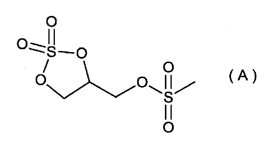
(4)リチウムジフルオロオキサレートボレート(LiDFOB)
(5)ビニレンカーボネート
(6)リチウムジフルオロホスフェート(LiDFP)
(5)ビニレンカーボネート
(6)リチウムジフルオロホスフェート(LiDFP)
[実施例1]
(非水電解質の調製)
フルオロエチレンカーボネート(FEC)及びエチルメチルカーボネート(EMC)がFEC:EMC=30:70の体積比で混合された混合溶媒にLiPF6を1mol dm-3の濃度で溶解させた溶液を作製した。さらに1,3-プロペンスルトンを上記溶液に対して2質量%添加し、非水電解質とした。
(非水電解質の調製)
フルオロエチレンカーボネート(FEC)及びエチルメチルカーボネート(EMC)がFEC:EMC=30:70の体積比で混合された混合溶媒にLiPF6を1mol dm-3の濃度で溶解させた溶液を作製した。さらに1,3-プロペンスルトンを上記溶液に対して2質量%添加し、非水電解質とした。
(正極の作製)
正極活物質として、α―NaFeO2型結晶構造を有し、Li1+αMe1-αO2(Meは遷移金属)で表されるリチウム遷移金属複合酸化物を用いた。ここで、LiとMeのモル比Li/Meは1.33であり、Meは、Ni及びMnからなり、Ni:Mn=1:2のモル比で含んでいる。
正極活物質として、α―NaFeO2型結晶構造を有し、Li1+αMe1-αO2(Meは遷移金属)で表されるリチウム遷移金属複合酸化物を用いた。ここで、LiとMeのモル比Li/Meは1.33であり、Meは、Ni及びMnからなり、Ni:Mn=1:2のモル比で含んでいる。
N-メチルピロリドン(NMP)を分散媒とし、上記正極活物質、導電剤であるアセチレンブラック(AB)、及び結着剤であるポリフッ化ビニリデン(PVdF)を94:4.5:1.5の質量比率で含有する正極ペーストを作製した。正極基材である厚さ15μmのアルミニウム箔の片面に、上記正極ペーストを塗布し、乾燥し、プレス後、切断し、幅30mm、長さ40mmの矩形状に正極活物質層が配置された正極を作製した。正極活物質層の厚さは約100μmであり、正極合剤が単位面積あたり14mg/cm2含まれる。上記正極は、120℃で14時間以上減圧乾燥して用いた。
(負極の作製)
幅30mm、長さ42mm、厚さ600μmのリチウム金属板を負極板とした。上記リチウム金属板は、金属樹脂複合フィルムを介して1.4MPaの圧力でプレスされ、金属光沢を有していた。また、上記リチウム金属板には、長さ5mmの端部のみにステンレス鋼製の負極基材を接続した。
幅30mm、長さ42mm、厚さ600μmのリチウム金属板を負極板とした。上記リチウム金属板は、金属樹脂複合フィルムを介して1.4MPaの圧力でプレスされ、金属光沢を有していた。また、上記リチウム金属板には、長さ5mmの端部のみにステンレス鋼製の負極基材を接続した。
(非水電解質蓄電素子の作製)
ポリアクリレートで表面改質した厚さ27μmのポリプロピレン製微孔膜をセパレータとして用いた。上記セパレータを4枚重ね合わせ、一辺を残して周囲を融着することで、3箇所の袋部を備えた袋状セパレータを作製した。上記袋状セパレータの中央の袋部に、上記負極を挿入し、その両側の袋部に、2枚の上記正極をそれぞれ正極活物質層が配置された面が負極と対向するように挿入した。このようにして、正負極の対向面を2面備えた積層型電極群を作製した。
ポリアクリレートで表面改質した厚さ27μmのポリプロピレン製微孔膜をセパレータとして用いた。上記セパレータを4枚重ね合わせ、一辺を残して周囲を融着することで、3箇所の袋部を備えた袋状セパレータを作製した。上記袋状セパレータの中央の袋部に、上記負極を挿入し、その両側の袋部に、2枚の上記正極をそれぞれ正極活物質層が配置された面が負極と対向するように挿入した。このようにして、正負極の対向面を2面備えた積層型電極群を作製した。
ケースである金属樹脂複合フィルムに、あらかじめ上記正極及び負極にそれぞれ接続したリード端子の開放端部が外部露出するように、上記電極群を収納し、注液孔となる部分を除いて封止し、上記非水電解質を注液後、注液孔を気密封止した。このようにして、非水電解質蓄電素子を作製した。
ここで、負極の単位面積あたりの容量は、対向する正極の単位面積あたりの容量の約15倍である。
ここで、負極の単位面積あたりの容量は、対向する正極の単位面積あたりの容量の約15倍である。
[実施例2から実施例9及び比較例1から比較例8]
用いた溶媒及び添加剤の種類及び量を表1に示すとおりとしたこと以外は、実施例1と同様にして、実施例2から実施例9及び比較例1から比較例8の非水電解質蓄電素子を得た。なお、以下、表中「-」は、相当する添加剤を用いていないことを示す。
用いた溶媒及び添加剤の種類及び量を表1に示すとおりとしたこと以外は、実施例1と同様にして、実施例2から実施例9及び比較例1から比較例8の非水電解質蓄電素子を得た。なお、以下、表中「-」は、相当する添加剤を用いていないことを示す。
[参考例1から参考例3]
負極活物質として、黒鉛を用いた。質量比で、黒鉛:スチレンブタジエンゴム:カルボキシメチルセルロース=96.7:2.1:1.2の割合(固形分換算)で含み、水を分散媒とする負極ペーストを作製した。この負極ペーストを、負極合剤が単位面積あたり10mg/cm2含まれるように、負極基材としての帯状の銅箔集電体の両面に塗布し、乾燥した。これをローラープレス機により加圧して負極活物質層を成型した後、80℃で14時間減圧乾燥して、負極中の水分を除去した。このようにして得た負極を用い、用いた溶媒及び添加剤の種類及び量を表1に示すとおりとしたこと以外は、実施例1と同様にして、参考例1から参考例3の非水電解質蓄電素子を得た。
得られた各非水電解質蓄電素子について、上記の方法を用いて、初回充放電前の体積を測定した。
(初回充放電)
得られた各非水電解質蓄電素子について、以下の条件にて初回充放電を行った。25℃で4.60Vまで充電電流0.1Cで定電流充電したのちに、4.60Vで定電圧充電した。充電の終了条件は、充電電流が0.05Cとなるまでとした。充電後に10分間の休止を設けた後に、25℃で2.00Vまで放電電流0.1Cで定電流放電した。
得られた各非水電解質蓄電素子について、以下の条件にて初回充放電を行った。25℃で4.60Vまで充電電流0.1Cで定電流充電したのちに、4.60Vで定電圧充電した。充電の終了条件は、充電電流が0.05Cとなるまでとした。充電後に10分間の休止を設けた後に、25℃で2.00Vまで放電電流0.1Cで定電流放電した。
(初期容量確認試験)
初回充放電後、以下の条件にて初期容量確認試験を行った。25℃で4.60Vまで充電電流0.1Cで定電流充電したのちに、4.60Vで定電圧充電した。充電の終了条件は、充電電流が0.05Cとなるまでとした。充電後に10分間の休止を設けたのちに、25℃で2.00Vまで放電電流1.0Cで定電流放電した。この試験で得られた放電容量を「初期放電容量」とした。
初回充放電後、以下の条件にて初期容量確認試験を行った。25℃で4.60Vまで充電電流0.1Cで定電流充電したのちに、4.60Vで定電圧充電した。充電の終了条件は、充電電流が0.05Cとなるまでとした。充電後に10分間の休止を設けたのちに、25℃で2.00Vまで放電電流1.0Cで定電流放電した。この試験で得られた放電容量を「初期放電容量」とした。
また、参考例1から参考例3の負極活物質として黒鉛を用いた負極については、25℃で4.50Vまで充電電流0.1Cで定電流充電したのちに、4.50Vで定電圧充電した以外は上記と同様に初回充放電及び初期容量確認試験を行った。
(充放電サイクル試験)
次いで、以下の充放電サイクル試験を行った。25℃において、充電電流0.33C、充電終止電圧4.60Vとして定電流定電圧充電した。充電の終了条件は、充電電流が0.05Cとなるまでとした。その後、10分間の休止期間を設けた。その後、放電電流0.33C、放電終止電圧2.00Vとして定電流放電を行い、その後、10分間の休止期間を設けた。この充放電を50サイクル実施した。
次いで、以下の充放電サイクル試験を行った。25℃において、充電電流0.33C、充電終止電圧4.60Vとして定電流定電圧充電した。充電の終了条件は、充電電流が0.05Cとなるまでとした。その後、10分間の休止期間を設けた。その後、放電電流0.33C、放電終止電圧2.00Vとして定電流放電を行い、その後、10分間の休止期間を設けた。この充放電を50サイクル実施した。
また、参考例1から参考例3の負極活物質として黒鉛を用いた非水電解質蓄電素子については、上記初期容量確認試験および充放電サイクル試験の充電終止電圧は、4.50Vである。
その後、初期容量確認試験と同様の方法にて、充放電サイクル試験後の放電容量確認試験を行った。この試験で得られた放電容量を充放電サイクル後の放電容量とした。初期放電容量に対する充放電サイクル試験後の放電容量の百分率を「50サイクル後容量維持率」とした。また、放電を終了した状態にある上記容量確認試験後の各非水電解質蓄電素子について、上記の方法を用いて、体積を測定し、初回充放電前の体積との差を算出し、体積増加量とした。
初期放電容量、50サイクル後放電容量維持率、及び体積増加量を表1に示す。
初期放電容量、50サイクル後放電容量維持率、及び体積増加量を表1に示す。

上記表1に示されるように、上記非水電解質の全溶媒における上記フッ素化環状カーボネートの含有量が20体積%を超え、且つ、硫黄系環状化合物を添加剤として含有する非水電解質を用いた実施例1から実施例9に係る非水電解質蓄電素子は、体積増加に対する抑制効果が高いことが確認された。
これに対し、上記フッ素化環状カーボネートの含有量が20体積%以下であるか、又は、硫黄系環状化合物を含有しない非水電解質を用いた比較例1から比較例8に係る非水電解質蓄電素子は、体積増加に対する抑制効果が劣っていた。このことから、非水電解質の全溶媒における上記フッ素化環状カーボネートの含有量が20体積%を超えること、及び、硫黄系環状化合物を添加剤として含有すること、の両方を組み合わせることによって、初めて、リチウム金属を含む負極活物質層を有する負極を備えた非水電解質蓄電素子の充放電サイクルにおける体積増加に対する抑制効果が向上することがわかる。
次に、50サイクル後放電容量維持率について、実施例1と、比較例1、比較例2、比較例5、及び比較例6とを対比すると、非水電解質の全溶媒における上記フッ素化環状カーボネートの含有量が20体積%を超えることにより、50サイクル後放電容量維持率が向上することがわかる。
一方、負極活物質として黒鉛を用いた参考例1から参考例3においては、参考例2と参考例3を比べてわかるように、非水電解質の全溶媒における上記フッ素化環状カーボネートの含有量が20体積%を超えることと、硫黄系環状化合物を添加剤として含有することとを組み合わせることによる体積増加に対する抑制効果が小さかった。
さらに、上記非水電解質の全溶媒における上記フッ素化環状カーボネートの含有量が20体積%を超え、且つ、硫黄系環状化合物を添加剤として含有する非水電解質を用いた参考例3及び実施例1と、卑な電位で分解されやすいことが知られているビニレンカーボネート及びLiDFPを添加剤として用いた参考例1及び比較例4とを対比すると、負極活物質としてリチウム金属を用いた比較例4は、実施例1と比較して体積増加に対する抑制効果が得られなかったのに対し、負極活物質として黒鉛を用いた参考例1は、参考例3と比較して体積増加に対して高い抑制効果が得られた。このことから、負極活物質として黒鉛を含む負極活物質層を有する負極を備える非水電解質蓄電素子と、リチウム金属を含む負極活物質層を有する負極を備える非水電解質蓄電素子とでは、充放電サイクルにおける体積増加の抑制効果の作用機構が大きく異なることが示唆される。これは、負極活物質として黒鉛を含む負極活物質層を有する負極を備える非水電解質蓄電素子においては、初回充電時に黒鉛上に形成されたビニレンカーボネートやLiDFP由来の被膜が充放電サイクルにおいても継続的に安定に存在し、非水電解質の電気化学的な還元分解による連続的なガスの発生を抑制するため、非水電解質蓄電素子の体積増加を抑制することができるのに対し、負極活物質としてリチウム金属を含む負極活物質層を有する負極を備える非水電解質蓄電素子においては、充放電サイクルにおいて生成する活性なリチウム金属上でのビニレンカーボネートやLiDFP由来の被膜の形成が遅いため、リチウム金属上での非水電解質の還元分解による連続的なガスの発生が起こり、これが体積増加の主な原因であることと関連していると考えられる。
以上の結果、当該非水電解質蓄電素子は、リチウム金属を含む負極活物質層を有する負極を備える非水電解質蓄電素子の充放電サイクルにおける体積増加に対する抑制効果に優れること、また、この効果は、負極活物質としてリチウム金属を含有する負極に対して選択的に効果を奏する特有の作用機構に基づくものであることが示された。
本発明は、パーソナルコンピュータ、通信端末等の電子機器、自動車等の電源として使用される非水電解質蓄電素子及び蓄電装置に適用できる。
1 非水電解質蓄電素子
2 電極体
3 ケース
4 正極端子
4’ 正極リード
5 負極端子
5’ 負極リード
20 蓄電ユニット
30 蓄電装置
2 電極体
3 ケース
4 正極端子
4’ 正極リード
5 負極端子
5’ 負極リード
20 蓄電ユニット
30 蓄電装置
Claims (4)
- 負極と、正極と、非水電解質とを備え、
上記負極がリチウム金属を含む負極活物質層を有し、
上記非水電解質がフッ素化環状カーボネート、鎖状カーボネート及び硫黄系環状化合物を含有し、
上記非水電解質の全溶媒における上記フッ素化環状カーボネートの含有量が20体積%を超える非水電解質蓄電素子。 - 上記フッ素化環状カーボネートがフルオロエチレンカーボネートである請求項1に記載の非水電解質蓄電素子。
- 上記硫黄系環状化合物がスルトン構造又は環状サルフェート構造を有する化合物である請求項1又は請求項2の非水電解質蓄電素子。
- 請求項1から3の何れか1項に記載の非水電解質蓄電素子を複数個備えた蓄電装置。
Priority Applications (4)
| Application Number | Priority Date | Filing Date | Title |
|---|---|---|---|
| CN202080064003.5A CN114402472A (zh) | 2019-09-11 | 2020-07-21 | 非水电解质蓄电元件和蓄电装置 |
| JP2021545149A JPWO2021049178A1 (ja) | 2019-09-11 | 2020-07-21 | |
| US17/641,475 US20220336860A1 (en) | 2019-09-11 | 2020-07-21 | Nonaqueous electrolyte energy storage device and energy storage apparatus |
| EP20863732.2A EP4030521A4 (en) | 2019-09-11 | 2020-07-21 | POWER STORAGE ELEMENT WITH ANHYDROUS ELECTROLYTE AND POWER STORAGE DEVICE |
Applications Claiming Priority (2)
| Application Number | Priority Date | Filing Date | Title |
|---|---|---|---|
| JP2019165770 | 2019-09-11 | ||
| JP2019-165770 | 2019-09-11 |
Publications (1)
| Publication Number | Publication Date |
|---|---|
| WO2021049178A1 true WO2021049178A1 (ja) | 2021-03-18 |
Family
ID=74866115
Family Applications (1)
| Application Number | Title | Priority Date | Filing Date |
|---|---|---|---|
| PCT/JP2020/028257 WO2021049178A1 (ja) | 2019-09-11 | 2020-07-21 | 非水電解質蓄電素子、及び蓄電装置 |
Country Status (5)
| Country | Link |
|---|---|
| US (1) | US20220336860A1 (ja) |
| EP (1) | EP4030521A4 (ja) |
| JP (1) | JPWO2021049178A1 (ja) |
| CN (1) | CN114402472A (ja) |
| WO (1) | WO2021049178A1 (ja) |
Citations (4)
| Publication number | Priority date | Publication date | Assignee | Title |
|---|---|---|---|---|
| JP2006318888A (ja) * | 2005-04-08 | 2006-11-24 | Sony Corp | 電解液および電池 |
| JP2008147119A (ja) * | 2006-12-13 | 2008-06-26 | Sony Corp | 電解液および電池 |
| JP2011124154A (ja) | 2009-12-11 | 2011-06-23 | Panasonic Corp | 非水電解質電池用活物質および非水電解質電池 |
| JP2018181772A (ja) * | 2017-04-20 | 2018-11-15 | 株式会社Gsユアサ | 非水電解質蓄電素子及びその製造方法 |
Family Cites Families (2)
| Publication number | Priority date | Publication date | Assignee | Title |
|---|---|---|---|---|
| JP6849920B2 (ja) * | 2015-10-15 | 2021-03-31 | セントラル硝子株式会社 | 非水電解液電池用電解液及びそれを用いた非水電解液電池 |
| JP7116311B2 (ja) * | 2017-12-12 | 2022-08-10 | セントラル硝子株式会社 | 非水電解液電池用電解液及びそれを用いた非水電解液電池 |
-
2020
- 2020-07-21 WO PCT/JP2020/028257 patent/WO2021049178A1/ja unknown
- 2020-07-21 US US17/641,475 patent/US20220336860A1/en active Pending
- 2020-07-21 EP EP20863732.2A patent/EP4030521A4/en active Pending
- 2020-07-21 JP JP2021545149A patent/JPWO2021049178A1/ja active Pending
- 2020-07-21 CN CN202080064003.5A patent/CN114402472A/zh active Pending
Patent Citations (4)
| Publication number | Priority date | Publication date | Assignee | Title |
|---|---|---|---|---|
| JP2006318888A (ja) * | 2005-04-08 | 2006-11-24 | Sony Corp | 電解液および電池 |
| JP2008147119A (ja) * | 2006-12-13 | 2008-06-26 | Sony Corp | 電解液および電池 |
| JP2011124154A (ja) | 2009-12-11 | 2011-06-23 | Panasonic Corp | 非水電解質電池用活物質および非水電解質電池 |
| JP2018181772A (ja) * | 2017-04-20 | 2018-11-15 | 株式会社Gsユアサ | 非水電解質蓄電素子及びその製造方法 |
Non-Patent Citations (1)
| Title |
|---|
| See also references of EP4030521A4 |
Also Published As
| Publication number | Publication date |
|---|---|
| JPWO2021049178A1 (ja) | 2021-03-18 |
| CN114402472A (zh) | 2022-04-26 |
| US20220336860A1 (en) | 2022-10-20 |
| EP4030521A4 (en) | 2023-12-06 |
| EP4030521A1 (en) | 2022-07-20 |
Similar Documents
| Publication | Publication Date | Title |
|---|---|---|
| JP6911655B2 (ja) | 蓄電素子用非水電解質、非水電解質蓄電素子、及び非水電解質蓄電素子の製造方法 | |
| WO2021132208A1 (ja) | 蓄電素子 | |
| JP7455498B2 (ja) | 非水電解質、非水電解質蓄電素子及び非水電解質蓄電素子の製造方法 | |
| EP3506412B1 (en) | Nonaqueous electrolyte energy storage device | |
| JP7409132B2 (ja) | 非水電解質蓄電素子 | |
| JP7076067B2 (ja) | 非水電解質二次電池、及び非水電解質二次電池の製造方法 | |
| US20230006188A1 (en) | Energy storage device | |
| JP2021190184A (ja) | 非水電解質蓄電素子 | |
| WO2021049178A1 (ja) | 非水電解質蓄電素子、及び蓄電装置 | |
| JP7363792B2 (ja) | 非水電解質蓄電素子及び非水電解質蓄電素子の製造方法 | |
| JP2020173998A (ja) | 非水電解質蓄電素子及び非水電解質蓄電素子の製造方法 | |
| JP6794656B2 (ja) | 二次電池用非水電解質、非水電解質二次電池、及び非水電解質二次電池の製造方法 | |
| JP7451994B2 (ja) | 蓄電素子 | |
| JP7451996B2 (ja) | 蓄電素子 | |
| JP7451995B2 (ja) | 蓄電素子 | |
| WO2021141074A1 (ja) | 非水電解質蓄電素子及びその製造方法 | |
| WO2023224071A1 (ja) | 非水電解質蓄電素子 | |
| EP4280330A1 (en) | Nonaqueous electrolyte power storage element | |
| WO2022138452A1 (ja) | 非水電解質蓄電素子、電子機器及び自動車 | |
| WO2022009734A1 (ja) | 非水電解質蓄電素子 | |
| WO2022239520A1 (ja) | 蓄電素子、その製造方法及び蓄電装置 | |
| US20240186514A1 (en) | Nonaqueous electrolyte energy storage device | |
| JP2022007093A (ja) | 非水電解液蓄電素子 | |
| JP2021048088A (ja) | 非水電解質蓄電素子 | |
| JP2023017587A (ja) | 非水電解質蓄電素子及びその製造方法 |
Legal Events
| Date | Code | Title | Description |
|---|---|---|---|
| 121 | Ep: the epo has been informed by wipo that ep was designated in this application |
Ref document number: 20863732 Country of ref document: EP Kind code of ref document: A1 |
|
| ENP | Entry into the national phase |
Ref document number: 2021545149 Country of ref document: JP Kind code of ref document: A |
|
| NENP | Non-entry into the national phase |
Ref country code: DE |
|
| ENP | Entry into the national phase |
Ref document number: 2020863732 Country of ref document: EP Effective date: 20220411 |