WO2021048941A1 - 伝動装置 - Google Patents
伝動装置 Download PDFInfo
- Publication number
- WO2021048941A1 WO2021048941A1 PCT/JP2019/035638 JP2019035638W WO2021048941A1 WO 2021048941 A1 WO2021048941 A1 WO 2021048941A1 JP 2019035638 W JP2019035638 W JP 2019035638W WO 2021048941 A1 WO2021048941 A1 WO 2021048941A1
- Authority
- WO
- WIPO (PCT)
- Prior art keywords
- case
- planetary gear
- oil
- gear
- transmission
- Prior art date
Links
Images


Classifications
-
- F—MECHANICAL ENGINEERING; LIGHTING; HEATING; WEAPONS; BLASTING
- F16—ENGINEERING ELEMENTS AND UNITS; GENERAL MEASURES FOR PRODUCING AND MAINTAINING EFFECTIVE FUNCTIONING OF MACHINES OR INSTALLATIONS; THERMAL INSULATION IN GENERAL
- F16H—GEARING
- F16H57/00—General details of gearing
- F16H57/04—Features relating to lubrication or cooling or heating
- F16H57/042—Guidance of lubricant
- F16H57/0421—Guidance of lubricant on or within the casing, e.g. shields or baffles for collecting lubricant, tubes, pipes, grooves, channels or the like
- F16H57/0423—Lubricant guiding means mounted or supported on the casing, e.g. shields or baffles for collecting lubricant, tubes or pipes
-
- F—MECHANICAL ENGINEERING; LIGHTING; HEATING; WEAPONS; BLASTING
- F16—ENGINEERING ELEMENTS AND UNITS; GENERAL MEASURES FOR PRODUCING AND MAINTAINING EFFECTIVE FUNCTIONING OF MACHINES OR INSTALLATIONS; THERMAL INSULATION IN GENERAL
- F16H—GEARING
- F16H57/00—General details of gearing
- F16H57/04—Features relating to lubrication or cooling or heating
- F16H57/0457—Splash lubrication
-
- F—MECHANICAL ENGINEERING; LIGHTING; HEATING; WEAPONS; BLASTING
- F16—ENGINEERING ELEMENTS AND UNITS; GENERAL MEASURES FOR PRODUCING AND MAINTAINING EFFECTIVE FUNCTIONING OF MACHINES OR INSTALLATIONS; THERMAL INSULATION IN GENERAL
- F16H—GEARING
- F16H48/00—Differential gearings
- F16H48/06—Differential gearings with gears having orbital motion
- F16H48/08—Differential gearings with gears having orbital motion comprising bevel gears
-
- F—MECHANICAL ENGINEERING; LIGHTING; HEATING; WEAPONS; BLASTING
- F16—ENGINEERING ELEMENTS AND UNITS; GENERAL MEASURES FOR PRODUCING AND MAINTAINING EFFECTIVE FUNCTIONING OF MACHINES OR INSTALLATIONS; THERMAL INSULATION IN GENERAL
- F16H—GEARING
- F16H48/00—Differential gearings
- F16H48/38—Constructional details
- F16H48/42—Constructional details characterised by features of the input shafts, e.g. mounting of drive gears thereon
-
- F—MECHANICAL ENGINEERING; LIGHTING; HEATING; WEAPONS; BLASTING
- F16—ENGINEERING ELEMENTS AND UNITS; GENERAL MEASURES FOR PRODUCING AND MAINTAINING EFFECTIVE FUNCTIONING OF MACHINES OR INSTALLATIONS; THERMAL INSULATION IN GENERAL
- F16H—GEARING
- F16H57/00—General details of gearing
- F16H57/04—Features relating to lubrication or cooling or heating
- F16H57/0409—Features relating to lubrication or cooling or heating characterised by the problem to increase efficiency, e.g. by reducing splash losses
-
- F—MECHANICAL ENGINEERING; LIGHTING; HEATING; WEAPONS; BLASTING
- F16—ENGINEERING ELEMENTS AND UNITS; GENERAL MEASURES FOR PRODUCING AND MAINTAINING EFFECTIVE FUNCTIONING OF MACHINES OR INSTALLATIONS; THERMAL INSULATION IN GENERAL
- F16H—GEARING
- F16H57/00—General details of gearing
- F16H57/04—Features relating to lubrication or cooling or heating
- F16H57/042—Guidance of lubricant
- F16H57/0421—Guidance of lubricant on or within the casing, e.g. shields or baffles for collecting lubricant, tubes, pipes, grooves, channels or the like
- F16H57/0424—Lubricant guiding means in the wall of or integrated with the casing, e.g. grooves, channels, holes
-
- F—MECHANICAL ENGINEERING; LIGHTING; HEATING; WEAPONS; BLASTING
- F16—ENGINEERING ELEMENTS AND UNITS; GENERAL MEASURES FOR PRODUCING AND MAINTAINING EFFECTIVE FUNCTIONING OF MACHINES OR INSTALLATIONS; THERMAL INSULATION IN GENERAL
- F16H—GEARING
- F16H57/00—General details of gearing
- F16H57/04—Features relating to lubrication or cooling or heating
- F16H57/042—Guidance of lubricant
- F16H57/0427—Guidance of lubricant on rotary parts, e.g. using baffles for collecting lubricant by centrifugal force
- F16H57/0428—Grooves with pumping effect for supplying lubricants
-
- F—MECHANICAL ENGINEERING; LIGHTING; HEATING; WEAPONS; BLASTING
- F16—ENGINEERING ELEMENTS AND UNITS; GENERAL MEASURES FOR PRODUCING AND MAINTAINING EFFECTIVE FUNCTIONING OF MACHINES OR INSTALLATIONS; THERMAL INSULATION IN GENERAL
- F16H—GEARING
- F16H57/00—General details of gearing
- F16H57/04—Features relating to lubrication or cooling or heating
- F16H57/0434—Features relating to lubrication or cooling or heating relating to lubrication supply, e.g. pumps ; Pressure control
- F16H57/0436—Pumps
-
- F—MECHANICAL ENGINEERING; LIGHTING; HEATING; WEAPONS; BLASTING
- F16—ENGINEERING ELEMENTS AND UNITS; GENERAL MEASURES FOR PRODUCING AND MAINTAINING EFFECTIVE FUNCTIONING OF MACHINES OR INSTALLATIONS; THERMAL INSULATION IN GENERAL
- F16H—GEARING
- F16H57/00—General details of gearing
- F16H57/04—Features relating to lubrication or cooling or heating
- F16H57/045—Lubricant storage reservoirs, e.g. reservoirs in addition to a gear sump for collecting lubricant in the upper part of a gear case
-
- F—MECHANICAL ENGINEERING; LIGHTING; HEATING; WEAPONS; BLASTING
- F16—ENGINEERING ELEMENTS AND UNITS; GENERAL MEASURES FOR PRODUCING AND MAINTAINING EFFECTIVE FUNCTIONING OF MACHINES OR INSTALLATIONS; THERMAL INSULATION IN GENERAL
- F16H—GEARING
- F16H57/00—General details of gearing
- F16H57/04—Features relating to lubrication or cooling or heating
- F16H57/0467—Elements of gearings to be lubricated, cooled or heated
- F16H57/0469—Bearings or seals
- F16H57/0471—Bearing
-
- F—MECHANICAL ENGINEERING; LIGHTING; HEATING; WEAPONS; BLASTING
- F16—ENGINEERING ELEMENTS AND UNITS; GENERAL MEASURES FOR PRODUCING AND MAINTAINING EFFECTIVE FUNCTIONING OF MACHINES OR INSTALLATIONS; THERMAL INSULATION IN GENERAL
- F16H—GEARING
- F16H57/00—General details of gearing
- F16H57/04—Features relating to lubrication or cooling or heating
- F16H57/0467—Elements of gearings to be lubricated, cooled or heated
- F16H57/0479—Gears or bearings on planet carriers
-
- F—MECHANICAL ENGINEERING; LIGHTING; HEATING; WEAPONS; BLASTING
- F16—ENGINEERING ELEMENTS AND UNITS; GENERAL MEASURES FOR PRODUCING AND MAINTAINING EFFECTIVE FUNCTIONING OF MACHINES OR INSTALLATIONS; THERMAL INSULATION IN GENERAL
- F16H—GEARING
- F16H57/00—General details of gearing
- F16H57/04—Features relating to lubrication or cooling or heating
- F16H57/048—Type of gearings to be lubricated, cooled or heated
- F16H57/0482—Gearings with gears having orbital motion
- F16H57/0483—Axle or inter-axle differentials
-
- F—MECHANICAL ENGINEERING; LIGHTING; HEATING; WEAPONS; BLASTING
- F16—ENGINEERING ELEMENTS AND UNITS; GENERAL MEASURES FOR PRODUCING AND MAINTAINING EFFECTIVE FUNCTIONING OF MACHINES OR INSTALLATIONS; THERMAL INSULATION IN GENERAL
- F16H—GEARING
- F16H57/00—General details of gearing
- F16H57/04—Features relating to lubrication or cooling or heating
- F16H57/048—Type of gearings to be lubricated, cooled or heated
- F16H57/0482—Gearings with gears having orbital motion
- F16H57/0486—Gearings with gears having orbital motion with fixed gear ratio
-
- F—MECHANICAL ENGINEERING; LIGHTING; HEATING; WEAPONS; BLASTING
- F16—ENGINEERING ELEMENTS AND UNITS; GENERAL MEASURES FOR PRODUCING AND MAINTAINING EFFECTIVE FUNCTIONING OF MACHINES OR INSTALLATIONS; THERMAL INSULATION IN GENERAL
- F16H—GEARING
- F16H57/00—General details of gearing
- F16H57/08—General details of gearing of gearings with members having orbital motion
-
- F—MECHANICAL ENGINEERING; LIGHTING; HEATING; WEAPONS; BLASTING
- F16—ENGINEERING ELEMENTS AND UNITS; GENERAL MEASURES FOR PRODUCING AND MAINTAINING EFFECTIVE FUNCTIONING OF MACHINES OR INSTALLATIONS; THERMAL INSULATION IN GENERAL
- F16H—GEARING
- F16H1/00—Toothed gearings for conveying rotary motion
- F16H1/28—Toothed gearings for conveying rotary motion with gears having orbital motion
-
- F—MECHANICAL ENGINEERING; LIGHTING; HEATING; WEAPONS; BLASTING
- F16—ENGINEERING ELEMENTS AND UNITS; GENERAL MEASURES FOR PRODUCING AND MAINTAINING EFFECTIVE FUNCTIONING OF MACHINES OR INSTALLATIONS; THERMAL INSULATION IN GENERAL
- F16H—GEARING
- F16H48/00—Differential gearings
- F16H48/38—Constructional details
- F16H2048/385—Constructional details of the ring or crown gear
-
- F—MECHANICAL ENGINEERING; LIGHTING; HEATING; WEAPONS; BLASTING
- F16—ENGINEERING ELEMENTS AND UNITS; GENERAL MEASURES FOR PRODUCING AND MAINTAINING EFFECTIVE FUNCTIONING OF MACHINES OR INSTALLATIONS; THERMAL INSULATION IN GENERAL
- F16H—GEARING
- F16H48/00—Differential gearings
- F16H48/38—Constructional details
- F16H48/42—Constructional details characterised by features of the input shafts, e.g. mounting of drive gears thereon
- F16H2048/423—Constructional details characterised by features of the input shafts, e.g. mounting of drive gears thereon characterised by bearing arrangement
-
- F—MECHANICAL ENGINEERING; LIGHTING; HEATING; WEAPONS; BLASTING
- F16—ENGINEERING ELEMENTS AND UNITS; GENERAL MEASURES FOR PRODUCING AND MAINTAINING EFFECTIVE FUNCTIONING OF MACHINES OR INSTALLATIONS; THERMAL INSULATION IN GENERAL
- F16H—GEARING
- F16H37/00—Combinations of mechanical gearings, not provided for in groups F16H1/00 - F16H35/00
- F16H37/02—Combinations of mechanical gearings, not provided for in groups F16H1/00 - F16H35/00 comprising essentially only toothed or friction gearings
- F16H37/04—Combinations of toothed gearings only
- F16H37/041—Combinations of toothed gearings only for conveying rotary motion with constant gear ratio
-
- F—MECHANICAL ENGINEERING; LIGHTING; HEATING; WEAPONS; BLASTING
- F16—ENGINEERING ELEMENTS AND UNITS; GENERAL MEASURES FOR PRODUCING AND MAINTAINING EFFECTIVE FUNCTIONING OF MACHINES OR INSTALLATIONS; THERMAL INSULATION IN GENERAL
- F16H—GEARING
- F16H57/00—General details of gearing
- F16H57/02—Gearboxes; Mounting gearing therein
- F16H57/021—Shaft support structures, e.g. partition walls, bearing eyes, casing walls or covers with bearings
-
- F—MECHANICAL ENGINEERING; LIGHTING; HEATING; WEAPONS; BLASTING
- F16—ENGINEERING ELEMENTS AND UNITS; GENERAL MEASURES FOR PRODUCING AND MAINTAINING EFFECTIVE FUNCTIONING OF MACHINES OR INSTALLATIONS; THERMAL INSULATION IN GENERAL
- F16H—GEARING
- F16H57/00—General details of gearing
- F16H57/08—General details of gearing of gearings with members having orbital motion
- F16H57/082—Planet carriers
Definitions
- the present invention provides a transmission device, particularly a sun gear, a ring gear concentrically arranged with the sun gear, a plurality of planetary gears that mesh with the sun gear and the ring gear, and a carrier that rotatably supports the plurality of planetary gears via a pivot axis.
- a speed reducer having a speed reducer, a differential case that receives a rotational force from the speed reducer, and a differential device that is arranged in the differential case and has a differential mechanism that distributes the rotational force to a pair of output shafts while allowing differential rotation.
- the "axial direction” means a direction along the central axis (rotational axis) of the transmission case
- the "circumferential direction” is a circumferential direction with respect to the central axis of the transmission case.
- the "diameter direction” means the radial direction with respect to the central axis of the transmission case.
- the transmission device is already known, for example, as disclosed in Patent Document 1 below.
- a transmission case including a carrier and a differential case coupled to the carrier is rotatably supported and housed in a transmission case via a pair of case support bearings 42 and 44, and is axially supported and accommodated.
- the specific planetary gear part of the two-stage planetary gear (that is, the large-diameter pinion 24) is specified on one side of the differential mechanism, and the other side of the differential mechanism (that is, the side that is axially far from the large-diameter pinion 24) is specified.
- Case support bearings 44 are arranged respectively.
- a large amount of lubricating oil is scattered from the large-diameter pinion 24 during transmission, but it is not easy to supply this scattered oil to a specific case support bearing 44 which is axially far from the large-diameter pinion 24.
- a predetermined amount of lubricating oil is stored in the bottom of the mission case, but if the stored oil level is set high, the amount of oil that repels the stored oil will increase as the transmission case rotates. At the same time, the stirring resistance of the lubricating oil received by the transmission case increases, which causes a decrease in transmission efficiency.
- the present invention has been proposed in view of the above, and an object of the present invention is to provide a transmission device capable of solving the above-mentioned problems with a simple structure.
- the present invention relates to a sun gear, a ring gear concentrically arranged with the sun gear and fixed to a transmission case, the sun gear and a plurality of planetary gears meshing with the ring gear, and the plurality of planetary gears.
- a speed reducer having a carrier that rotatably supports each planetary gear via a pivot shaft, a differential case that receives a rotational force from the speed reducer, and a differential case that is arranged in the differential case to transmit the rotational force to a pair of output shafts.
- a transmission case including a differential device having a differential mechanism that allows and distributes dynamic rotation, and the carrier and the differential case coupled to the carrier is provided with at least a pair of case support bearings in the mission case.
- a specific planetary gear portion of the planetary gear is rotatably supported and accommodated on one side of the differential mechanism in the axial direction, and a specific case support bearing is provided on the other side of the differential mechanism.
- an oil collecting portion opened upward and capable of collecting lubricating oil that is repelled around the specific planetary gear portion in the mission case as the transmission case rotates, and the above-mentioned
- An oil passage forming body connected to the oil collecting section and having an oil storing section for storing the lubricating oil collected by the oil collecting section and supplying the lubricating oil to the specific case support bearing is provided on the inner wall of the mission case.
- the first feature is that it is provided.
- the planetary gear is formed in a first planetary gear portion that meshes with the sun gear and a diameter smaller than that of the first planetary gear portion, and the specific case in the axial direction. It is a two-stage planetary gear that is located near a support bearing and integrally has a second planetary gear portion that meshes with the ring gear, and the first planetary gear portion constitutes the specific planetary gear portion. It is a feature of 2.
- the oil collecting portion is viewed on a projection plane orthogonal to the rotation axis of the transmission case, and the oil collecting portion is on one side of a vertical line passing through the rotation axis.
- the half-circumferential portion of the transmission case is arranged in the middle portion in the circumferential direction of the half-circumferential portion of the mission case.
- the third feature is that it is a half-circumferential portion on the side that moves in the circumferential direction.
- the oil passage forming body is attached to the mission case so as to pass through a mounting groove recessed in the inner circumference of the mission case. It is composed of a gutter-shaped member, and the inner circumference of the mission case has a notch that guides lubricating oil that runs down the inner peripheral surface of the mission case above the mounting groove to the upper opening of the oil collecting portion.
- a fourth feature is that the shaped recess is formed so as to coincide with at least a part of the oil collecting portion in the axial direction.
- the oil storage portion is arranged so as to pass through a space between the ring gear and the transmission case in the radial direction. It is a feature of.
- the ring gear is fitted and fixed to the inner peripheral surface of the mission case, and a plurality of detents arranged at intervals in the circumferential direction on the outer peripheral surface of the ring gear.
- the oil storage portion integrally has a protrusion for rotation, and the oil storage portion faces the outer peripheral surface of the ring gear between two adjacent protrusions for preventing rotation in the circumferential direction on the outer peripheral side of the ring gear.
- the sixth feature is that it is arranged so as to pass through the space.
- the transmission case repels the lubricating oil stored in the bottom portion of the mission case on the outer circumference around the specific planetary gear portion.
- a seventh feature is that it integrally has a plurality of possible flip-up protrusions.
- the case support bearing is a bearing that is projected from the transmission case and rotatably fits and supports the outer periphery of one of the output shafts.
- the boss portion is interposed between the boss portion and the annular transmission case support portion that is projected from the transmission case and one of the output shafts penetrates the inside in the axial direction, and the mission case is formed of the transmission case support portion.
- the oil passage forming body has a notch portion that communicates the outer peripheral portion and the inner peripheral portion, and the downstream end of the oil passage forming body reaches the notch portion, and the lubricating oil that has flowed through the oil passage forming body is applied to the one side.
- the eighth feature is that it can be supplied to the fitting portion between the output shaft of the above and the bearing boss portion.
- a transmission device in which a specific planetary gear portion of a planetary gear is arranged on one side of the differential mechanism and a specific case support bearing is arranged on the other side of the differential mechanism, the inside of the transmission case is inside the transmission case as the transmission case rotates.
- An oil collecting part that opens upward and can collect the lubricating oil that is repelled around the specific planetary gear part, and a lubricating oil that is connected to the oil collecting part and collected by the oil collecting part are stored and specified.
- An oil passage forming body including an oil storage portion for supplying the case support bearing is provided on the inner wall of the mission case.
- the specific planetary gear portion and the specific case support bearing are arranged at positions separated from each other with the differential mechanism sandwiched in the axial direction, the lubricating oil repelled around the specific planetary gear portion is passed through the oil passage. Since it can be collected by the oil collecting part of the formed body and flowed and supplied to a specific case support bearing distant in the axial direction through the oil passage forming body, sufficient lubrication should be performed on the specific case support bearing. Can be done.
- the oil passage forming body is formed.
- the auxiliary tank function that can temporarily store a relatively large amount of lubricating oil during the transmission of the transmission device, and the stored oil level in the mission case during transmission can be set lower by that amount.
- the stirring resistance of the lubricating oil received by the transmission case can be reduced, and the decrease in transmission efficiency due to the oil splashing can be suppressed.
- the specific planetary gear portion is the large-diameter first planetary gear portion of the two-stage planetary gear
- the large-diameter first planetary gear portion momentums the lubricating oil at the bottom of the mission case. It can be repelled well, which enhances the oil collecting effect of the oil collecting part.
- the oil collecting portion is in the circumferential direction of the half-circumferential portion of the mission case on one side of the vertical straight line passing through the rotation axis when viewed from the projection plane orthogonal to the rotation axis of the transmission case.
- the half-circumferential portion of the mission case on one side which is arranged in the middle portion, is the half-circumferential portion on the side where the outer peripheral portion of the transmission case during normal rotation moves in the circumferential direction from the top to the bottom of the mission case.
- the oil passage forming body is composed of a gutter-shaped member attached to the mission case so as to pass through a mounting groove recessed in the inner circumference of the mission case, and is formed on the inner circumference of the mission case.
- the notch-shaped recess that guides the lubricating oil that runs down the inner peripheral surface of the mission case above the mounting groove to the upper opening of the oil collecting part aligns the axial position with at least a part of the oil collecting part. It is formed in this way.
- the lubricating oil that scatters from the periphery of the specific planetary gear portion of the transmission case during normal rotation and tends to flow downward along the inner peripheral surface of the mission case is more efficiently collected in the oil collecting portion. be able to.
- the oil storage portion is arranged so as to pass through the space between the ring gear and the transmission case in the radial direction, the specific planetary gear portion and the specific case support bearing are separated by the ring gear. Even if the transmission case is divided in the axial direction on the inner surface, the lubricating oil can flow and be supplied beyond the ring gear without any trouble.
- a plurality of anti-rotation protrusions arranged at intervals in the circumferential direction are projected on the outer peripheral surface of the ring gear fitted and fixed to the inner circumference of the mission case to form an oil passage. Since the oil storage part of the body passes between the two anti-rotation protrusions adjacent to each other in the circumferential direction on the outer peripheral side of the ring gear, the space on the outer peripheral side of the ring gear is used between the two anti-rotation protrusions. Then, the oil storage section can be easily handled.
- a plurality of repelling protrusions capable of repelling the lubricating oil stored in the bottom of the mission case are integrally formed on the outer periphery of the transmission case around the specific planetary gear portion. Therefore, the lubricating oil at the bottom of the mission case can be more efficiently repelled by the repelling protrusion on the outer periphery of the transmission case, and the oil collecting effect by the oil collecting portion can be further enhanced.
- the case support bearing is provided with a bearing boss portion that is projected from the transmission case to rotatably fit and support the outer circumference of one output shaft, and one that is projected from the transmission case.
- the output shaft is interposed between the annular transmission case support portion that penetrates the inside in the axial direction, and the mission case has a notch portion that communicates the outer peripheral portion and the inner peripheral portion of the transmission case support portion.
- the downstream end of the oil passage forming body reaches the notch portion, and the lubricating oil flowing through the oil passage forming body can be supplied to the fitting portion between one output shaft and the bearing boss portion.
- the fitting portion between the output shaft and the inner circumference of the bearing boss portion is separated from the internal space of the mission case by the case support bearing, the fitting portion of the mission case support portion through the notch portion from the oil passage forming body. Since the lubricating oil can be supplied to the inner side in the radial direction, the fitting portion between the output shaft and the inner circumference of the bearing boss portion can be directly lubricated with the lubricating oil supplied from the oil passage forming body.
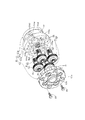
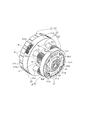
- FIG. 1 is an overall vertical sectional view (a sectional view taken along line 1-1 of FIG. 2) showing a transmission device according to an embodiment of the present invention.
- FIG. 2 is a sectional view taken along line 2-2 of FIG.
- FIG. 3 is a sectional view taken along line 3-3 of FIG.
- FIG. 4 is a sectional view taken along line 4-4 of FIG.
- FIG. 5 is a sectional view taken along line 5-5 of FIG.
- FIG. 6 is a sectional view taken along line 6-6 of FIG.
- FIG. 7 is a plan sectional view (cross-sectional view taken along line 7-7 of FIG.
- FIG. 8 is an exploded perspective view of the transmission device.
- FIG. 9 is an exploded perspective view of a main part of the transmission device in which the mission case is omitted.
- FIG. 10 is a perspective view showing how the oil passage forming body is attached to the main body of the mission case.
- FIG. 11 is a perspective view of a main part of the transmission device in which the mission case is omitted.
- Transmission case 21Ao Outer peripheral wall portion 21b2 of the first end wall as a specific outer peripheral wall portion ... Bearing boss portion 2nd bearing boss 31 ... Sun gear 32 ... Ring gear 32t ... Detent protrusion 33 ... Axle 40 ... Diff case 41 ... -Differential gear mechanism 51, 52 as a differential mechanism ... First and second output shafts as a pair of output shafts
- a vehicle for example, a transmission device A mounted on an automobile is rotatably housed and supported in a mission case 10 fixedly supported by a support portion 13 (for example, a vehicle body) and the mission case 10.
- a transmission case 20 and a speed reducer R that is deployed in the transmission case 20 to reduce and transmit power from a power source (for example, an in-vehicle electric motor) (not shown), and also deployed in the transmission case 20.
- a differential device D is provided which distributes and transmits the output of the speed reducer R to the first and second output shafts 51 and 52 while allowing differential rotation. Then, the first and second output shafts 51 and 52 interlock and rotate the left and right drive wheels via an interlocking mechanism (not shown).
- the mission case 10 is vertically divided into, for example, a bottomed cylindrical mission case main body 11 and a lid body 12 that closes the open end of the mission case main body 11.
- the mission case main body 11 is formed so that its body portion 11a gradually becomes smaller in diameter (in a stepwise manner in the illustrated example) as it approaches the end wall portion 11s.
- an intermediate portion of the second output shaft 52 is fitted into the central hole of the end wall portion 11s via the seal member 14.
- a cover plate 15 for protecting and supporting the seal member 14 is screwed to the end wall portion 11s.
- the lid body 12 has a disk-shaped end plate portion 12s that is detachably joined to the open end of the mission case main body 11 with a plurality of bolts B1 and a body that is integrally projected on the outer surface of the end plate portion 12s. A part 12a is provided. Further, the end plate portion 12s is detachably fixed to the support portion 13 with a plurality of bolts B2.
- the transmission case 20 is provided on the first and second support boss portions 12b and 11b projecting inward on the inner surfaces of both end walls (more specifically, the end plate portions 12s and the end wall portions 11s described above) of the mission case 10.
- the first and second case support bearings Bc1 and Bc2 are rotatably supported around the first axis X1.
- the first axis X1 becomes the rotation axis of the transmission case 20.
- the transmission case 20 can be charged into the mission case main body 11 from the outside in the axial direction through the facing surfaces of the mission case main body 11 and the lid 12 (that is, the open end of the mission case main body 11).
- the transmission case 20 of the present embodiment can be attached to and detached from the transmission case main body 21 which is the main part thereof and the disk-shaped first end wall (that is, one end wall) 21A of the transmission case main body 21 with a plurality of bolts B3. It is divided and configured by a part of the speed reducer R (that is, the first carrier portion C1 described later) to be joined.
- the transmission case main body 21 includes the first end wall 21A, a disk-shaped second end wall 21B facing the first end wall 21A at an axial distance, and the first and second end walls 21A. It is provided with a plurality of connecting walls 21L (two in the illustrated example) that integrally connect the 21Bs.
- the connecting wall 21L exists at a position different in the circumferential direction from the planetary gear P and the pivot 33 described later of the speed reducer R.
- each half of the first and second end walls 21A and 21B on the inner side in the radial direction and the connecting wall 21L cooperate with each other to form a differential case of the differential device D. Functions as 40.
- the first and second output shafts 51 and 52 are rotatably fitted and supported on both end walls of the differential case 40, that is, on the outer surfaces on the center side of the first and second end walls 21A and 21B, respectively.
- the first and second bearing boss portions 21b1, 21b2 facing each other are integrally projected.
- Spiral grooves G2 and G3 are recessed on at least one of the fitting surfaces of the first and second output shafts 51 and 52 and the first and second bearing boss portions 21b1, 21b2. These spiral grooves G2 and G3 exert a screw pumping action when relative rotation occurs between the fitting surfaces due to normal rotation (advancement of the vehicle) of the first and second output shafts 51 and 52. It functions as a pump that forcibly sends the lubricating oil in the transmission case 10 into the differential case 40 to the fitting surface and the adjacent movable portion (for example, the differential gear mechanism 41).
- Each tip of the first and second bearing bosses 21b1, 21b2 has an oil suction protrusion for scraping the lubricating oil around the tip into the spiral grooves G2 and G3 during the relative rotation. , Corresponding to the outer open ends of the spiral grooves G2 and G3, respectively.
- the speed reducer R includes a sun gear 31 facing the transmission case 20, a ring gear 32 arranged concentrically with respect to the sun gear 31 at a position offset in the axial direction from the sun gear 31, and a plurality of gears 31 meshing with the sun gear 31 and the ring gear 32 (FIG. FIG.
- the example has four planetary gears P) and a carrier C that rotatably supports a plurality of planetary gears P via a pivot 33.
- the planetary gear P is formed with a diameter smaller than that of the first planetary gear portion P1 and the ring gear 32 that meshes with the sun gear 31 and is located close to the second case support bearing Bc2 in the axial direction. It is a two-stage planetary gear that integrally has a second planetary gear portion P2 that meshes with the gear, and is formed coaxially and integrally with the pivot 33 in the present embodiment.
- the first and second planetary gear portions P1 and P2, the sun gear 31, and the ring gear 32 have gear teeth (helical teeth in the present embodiment) that generate a thrust load by the reaction force of the meshing.
- the outer periphery of the intermediate portion of the sun gear 31 is rotatably supported by the mission case 10 (lid body 12) via bearings Bs. Moreover, the inner peripheral surface of the sun gear 31 is rotatably fitted and supported on the outer peripheral surface of the first bearing boss portion 21b1 described above. Therefore, the sun gear 31 and the first bearing boss portion 21b1 are aligned in the axial direction. The parts are arranged so that they overlap.
- the outer end portion of the sun gear 31 (not shown) is interlocked and connected to the output side of a power source (not shown) via an interlocking mechanism (not shown).
- the inside of the transmission case 20 flows from the outer peripheral side to the central side of the case with the operation of the speed reducer R.
- a first space portion 25 through which a part of the lubricating oil can flow in is interposed.
- a spiral groove-shaped oil passage G1 having one end communicating with the first space portion 25 is provided.
- the other end of the oil passage G1 is defined between the central hole 31h of the sun gear 31 and the outer peripheral portion of the first output shaft 51 on the axially outer side of the first bearing boss portion 21b1. 2 Opens in the space 26.
- the oil passage G1 communicates with the fitting portion between the first bearing boss portion 21b1 and the first output shaft 51 via the second space portion 26, and lubricating oil can be supplied to the fitting portion.
- the oil passage G1 described above has a spiral groove shape, the same as the spiral grooves G2 and G3 described above, when the fitting surfaces rotate relative to each other due to the normal rotation of the sun gear 31 (advancement of the vehicle).
- the lubricating oil of the first space portion 25 can be fed to the second space portion 26 side by exerting a screw pumping action.
- the oil passage G1 may be formed in a groove form (for example, a straight groove) other than the spiral groove. Further, in the present embodiment, the oil passage G1 is provided on the outer peripheral surface of the first bearing boss portion 21b1, but the oil passage G1 may be provided on the inner peripheral surface of the sun gear 31.
- the outer peripheral surface of the ring gear 32 is fitted and fixed to the inner peripheral surface of the axially intermediate portion of the transmission case main body 11 (more specifically, the body portion 11a) (for example, the ring gear 32 is engaged by a locking means 70 such as a circlip). It will be stopped).
- a large number of anti-rotation protrusions 32t are integrally formed on the outer peripheral surface of the ring gear 32 at intervals in the circumferential direction, and the anti-rotation protrusions 32t have a spline groove shape on the inner peripheral surface of the body portion 11a. It engages with a large number of detent grooves formed in the above so that it cannot rotate relative to each other.
- the ring gear 32 is formed so that the inner diameter thereof is smaller than the maximum outer diameter of the second end wall 21B.
- the carrier C is the first carrier portion C1 that supports one end of the pivot 33 of the planetary gear P, that is, the outer end of the first planet gear portion P1, and the other end of the pivot 33, that is, the second planet. It is divided into a second carrier portion C2 that supports the outer end on the gear portion P2 side.
- the first carrier portion C1 integrally has a boss portion C1b projecting outward in the axial direction from the outer surface thereof on the outward side in the axial direction with respect to the first bearing boss portion 21b1.
- the first case support bearing Bc1 that rotatably supports one end side of the transmission case 20 is interposed between the boss portion C1b and the support boss portion 12b on the inner surface of the mission case 10 (lid body 12).
- the second carrier portion C2 is integrated with the second end wall 21B of the transmission case main body 21. That is, the radial outer half of the second end wall 21B functions as the second carrier portion C2.
- first planetary gear portion P1 side is connected to the first carrier portion C1 of the transmission case 20 via the first bearing Bp1, and the other end portion on the second planet gear portion P2 side. Is supported by the second carrier portion C2 of the transmission case 20 via the second bearing Bp2.
- first and second bearings Bp1 and Bp2 only the first bearing Bp1 has a bearing structure (for example, a ball bearing) capable of receiving both the radial load and the thrust load on one side and the other side in the axial direction. Ru.
- a bearing for example, a needle bearing
- the second end wall 21B of the transmission case 20, particularly the portion that functions as the second carrier portion C2, is formed so as to penetrate the second end wall 21B so as to pass the second bearing Bp2.
- the recess 21z1 whose bottom surface is located inward in the axial direction from the outer end in the axial direction and the second output shaft 52 projecting outward in the axial direction from the bottom surface of the recess 21z1 are rotatably fitted. It is provided with a second bearing boss portion 21b2 to support.
- the bearing hole 21h4 is an example of the pivot support portion, and is also an example of the insertion hole for the second planetary gear, which will be described later.
- the outer peripheral portion of the second bearing boss portion 21b2 is supported by the second support boss portion 11b projecting from the inner surface of the mission case 10 via the second case support bearing Bc2. Moreover, at least a part of each of the second case support bearing Bc2 and the second support boss portion 11b is arranged in the recess 21z1. In other words, the second case support bearing Bc2, the second support boss portion 11b, and the recess 21z1 are arranged so as to partially overlap with the second bearing Bp2 in the axial direction.
- recesses 21z2 are formed between the second bearing boss portion 21b2 in the radial direction and the second bearing Bp2 adjacent to each other in the circumferential direction on the outer side of the recess 21z1. It is formed.
- An annular oil holding plate 27 as an oil holding member covering the radial outer portion of the opening surface of the recess 21z2 and the radial outer portion of the axial outer end of the second bearing Bp2 is clearly shown in FIG.
- the bearings are arranged so as to extend in the circumferential direction across the recess 21z2 and the second bearing Bp2. Then, the oil holding plate 27 is detachably fixed (for example, screwed) to the outer surface of the second end wall 21B.
- the oil holding plate 27 is formed in an annular shape, and the radial outer portion of the opening surface of all the recesses 21z2 and the radial outer portion of the axial outer end of all the second bearings Bp2.
- the oil holding plate 27 is formed in an arc shape extending in the circumferential direction of the second end wall 21B, and the opening surface of a part of the recess 21z2 is formed in the radial direction and a part of the recess 21z2.
- the second bearing Bp2 may cover the radial outer end of the second bearing Bp2.
- first planetary gear portion P1 of the planetary gear P is an example of the specific planetary gear portion, and is arranged between the facing surfaces of the first end wall 21A of the transmission case main body 21 and the first carrier portion C1.
- a gear pump chamber 28 for accommodating the first planetary gear portion P1 is defined on the facing surfaces thereof.
- the gear pump chamber 28 is formed by forming a recess 21Ac for drawing the pump chamber on one surface of the facing surfaces (that is, the outer surface of the first end wall 21A). Is defined between the surface facing the other surface (that is, the inner surface of the first carrier portion C1). Contrary to the present embodiment, it is also possible to carry out a modified example in which a recess for drawing a pump chamber is formed on the other surface of the facing surface (that is, the inner surface of the first carrier portion C1). Further, it is also possible to carry out a modified example in which the recess 21Ac for drawing the pump chamber is formed on both the outer surface of the first end wall 21A and the inner surface of the first carrier portion C1 among the facing surfaces.
- the outer diameter of the gear tooth of the first planetary gear portion P1 and the inner diameter of the gear pump chamber 28 are substantially the same, that is, the gear tooth and the inner peripheral surface of the gear pump chamber 28 are in the radial direction. Opposite and close to each other. Further, the axially opposite surfaces of the first planetary gear portion P1 and the axially both inner surfaces of the gear pump chamber 28 (that is, the bottom surface of the recess 21Ac and the inner surface of the first carrier portion C1) are in the axial direction. It is in a relatively close position.
- the lubricating oil held in the valleys of the gear teeth of the first planetary gear portion P1 moves from the outer peripheral side to the central portion of the transmission case 20 along the inner peripheral surface of the gear pump chamber 28. A part of the feed is also supplied to the first space 25 between the tip surface of the sun gear 31 and the outer surface of the first end wall 21A.
- the first planetary gear portion P1 and the gear pump chamber 28 form a gear pump GP that is responsible for supplying the lubricating oil.
- each gear tooth of the first planet gear portion P1 is a gear of the sun gear 31 from the outer side in the axial direction thereof.
- first carrier portion C1 and the first end wall 21A are at a height at which a part of these outer peripheral wall portions C1o and 21Ao is immersed in the lubricating oil stored in the bottom portion of the mission case 10.
- a plurality of repelling protrusions 2t capable of repelling the stored lubricating oil in the mission case 10 are provided on the outer peripheral wall portion C1o of the first carrier portion C1 of the present embodiment at intervals in the circumferential direction. ..
- Each of the outer peripheral wall portions C1o and 21Ao described above is an outer peripheral portion having the maximum outer diameter of the transmission case 20, and is an example of a specific outer peripheral wall portion of the transmission case 20.
- the outer peripheral wall portion 21Ao of the first end wall 21A has a plurality of oil introduction windows 21Aw that expose a part of the first planetary gear portion P1 from the outer peripheral surface of the transmission case 20, and each oil introduction window 21Aw has a plurality of oil introduction windows 21Aw.
- It is arranged adjacent to a part of the flip-up protrusion 2t in the axial direction.
- the flip-up protrusion 2t can be installed in place of or in addition to the structure shown in the illustrated example at a portion of the outer peripheral wall portion 21Ao of the first end wall 21A adjacent to the oil introduction window 21Aw.
- the oil introduction window of the gear pump GP is the outer peripheral wall portion C1o of the first carrier portion C1. It is provided in.
- the differential device D is a combination of the first and second end walls 21A and 21B and the connecting wall 21L, and is arranged in the differential case 40 and the differential case 40 that receives a rotational force from the speed reducer R (carrier C). It is provided with a differential gear mechanism 41 that distributes the rotational force of the differential case 40 to the pair of output shafts 51 and 52 while allowing differential rotation.
- the differential gear mechanism 41 is an example of the differential mechanism.
- both ends of the differential gear mechanism 41 are fitted and fixed to the pair of connecting walls 21L of the transmission case main body 21 (in the illustrated example, the press-fit pin 47 prevents them from coming off).
- a pinion shaft 42 arranged on the second axis X2 orthogonal to the first axis X1, a plurality of pinion gears 43 rotatably supported by the pinion shaft 42 (two in the illustrated example), and each pinion gear. It includes left and right side gears 44 that mesh with 43 and can rotate around the first axis X1.
- the pinion gear 43 and the side gear 44 are examples of differential mechanism constituent gears.
- the pinion gear 43 and the side gear 44 are composed of bevel gears in this embodiment. Both side gears 44 function as output gears of the differential gear mechanism 41, and the inner end portions of the first and second output shafts 51 and 52 are spline-fitted to the inner peripheral surfaces of both side gears 44, respectively.
- each pinion gear 43 is rotatably supported on the spherical inner surface of the connecting wall 21L around the second axis X2 via a washer, and the flat back surface of each side gear 44 is the first. , It is rotatably supported on the opposite surfaces of the second end walls 21A and 21B around the first axis X1 via a washer.
- the washer may be omitted if necessary.
- the rotational driving force transmitted from the carrier C to the transmission case main body 21 allows differential rotation with respect to the first and second output shafts 51 and 52 by the differential gear mechanism 41. It is distributed while. Since the differential function of the differential gear mechanism 41 is well known in the past, the description thereof will be omitted.
- the transmission case main body 21 is provided with a work window 21w that allows the pinion gear 43 and the side gear 44 to be assembled into the differential case 40 between the first and second end walls 21A and 21B.
- the work window 21w is defined between the edges of two connecting walls 21L adjacent to each other in the circumferential direction, which are adjacent to each other in the circumferential direction and extend linearly along the rotation axis X1.
- the above assembly work is performed as follows, for example. First, in a state where the pair of side gears 44 are assembled to the differential case 40 through the work window 21w, the pinion gear 43 is incorporated to the meshing position with the side gear 44 through the work window 21w. Next, while maintaining the meshed state, the back surface of the gear is brought into contact with the pinion gear support surface of the connecting wall 21L by revolving the pinion gear 43 around the side gear 44. Then, the pinion shaft 42 is inserted into the pinion gear 43 and the connecting wall 21L in the contact state, and the pinion shaft 42 is fixed to the connecting wall 21L with the press-fit pin 47.
- the work window 21w provides a rotation locus of at least the meshing portion (in the present embodiment, the entire tooth surface) of the tooth surface of all the differential mechanism constituent gears (that is, the pinion gear 43 and the side gear 44) constituting the differential gear mechanism 41. It has a size (more specifically, each opening width in the axial direction and the circumferential direction) that is exposed to the outside of the transmission case 20 over the entire axial width of the rotation locus.
- the opening surface of the work window 21w of the present embodiment is formed in a shape that allows the rotation locus to project outward from the opening surface, as is clearly shown in FIG.
- the opening surface of the work window 21w is located on a virtual plane of two connecting walls 21L adjacent to each other in the circumferential direction, connecting the edges adjacent to each other in the circumferential direction and orthogonal to the paper surface of FIG. Therefore, it is clear from the positional relationship that the rotation locus projects outward from the opening surface.
- the lubricating oil scattered from the second planetary gear portion P2 during the operation of the speed reducer R is discharged from at least the tooth surfaces of all the differential mechanism constituent gears (that is, each pinion gear 43 and each side gear 44) in the differential case 40. It is possible to directly supply the meshing portion (in the present embodiment, the entire tooth surface), and conversely, the lubricating oil scattered from the tooth surfaces of the differential mechanism constituent gears 43 and 44 can be directly supplied to the second planetary gear portion P2. Therefore, the lubrication effect on the differential device D and the speed reducer R can be enhanced with a simple structure.
- the working window 21w exposes the meshing portion to the outside of the transmission case 20 over the entire axial width of the rotation locus, so that the lubricating oil scattered in the transmission case 20 is applied. It becomes easy to supply to the meshing portion, and the lubricating effect is further enhanced. Moreover, since the opening surface of the work window 21w is formed in a shape that causes the rotation locus of the meshing portion to project outward from the opening surface, the rotation locus (hence, the meshing portion) is set to the second planetary gear portion.
- the lubricating oil scattered from the second planetary gear portion P2 can be more efficiently supplied to the meshing portion, and vice versa, from the differential mechanism constituent gears 43 and 44. Since the scattered lubricating oil can be more efficiently supplied to the second planetary gear portion P2, the lubricating effect is further enhanced.
- the second planetary gear portion P2 and the differential gear mechanism 41 are arranged in the axial direction.
- the transmission case 20 can be miniaturized in the axial direction by the length that overlaps with each other.
- the transmission case main body 21 of the transmission case 20 is integrally cast and molded as a whole.
- the transmission case main body 21 has the first and second output shaft insertion holes 21h1, 21h2 into which the first and second output shafts 51 and 52 can be inserted from both outer sides in the axial direction.
- the planetary gears P are provided with insertion holes 21h3 and 21h4 for the first and second planetary gears into which the planetary gear P can be inserted from the side facing the first carrier portion C1 in the axial direction.
- the insertion holes 21h1,21h2 for the first and second output shafts correspond to the central holes of the above-mentioned first and second bearing boss portions 21b1,21b2, and the insertion holes 21h3 for the first planetary gear correspond to this. It is formed through the first end wall 21A with an inner diameter that allows the second planetary gear portion P2 to pass through. Further, the insertion hole for the second planetary gear is composed of the bearing hole 21h4 provided in the second end wall 21B described above.
- the first planetary gear portion P1 of the planetary gear P is on one side (left side in FIG. 1) of the differential gear mechanism 41 in the axial direction, and the other side of the differential gear mechanism 41.
- a second case support bearing Bc2 as a specific case support bearing is arranged on the (right side in FIG. 1) side. That is, the first planetary gear portion P1 and the second case support bearing Bc2 are located at positions separated from each other with the differential gear mechanism 41 in the axial direction.
- the second case support bearing Bc2 is in the mission case 10.
- the scattered lubricating oil from the speed reducer R and the differential device D is located in a portion where it is difficult to reach sufficiently.
- a ring gear 32 is fitted between the first planetary gear portion P1 and the second case support bearing Bc2 on the inner peripheral surface of the mission case main body 11, and this serves as a wall to prevent the scattering of lubricating oil. There is a risk.
- the outer peripheral wall portions C1o and 21Ao of the first carrier portion C1 and the first end wall 21A are the maximum outer diameter portions of the transmission case 20, that is, the specific outer peripheral wall portions, and are used for rotation of the transmission case 20.
- a large amount of stored lubricating oil at the bottom of the mission case 10 can be repelled.
- an oil supply structure is added to efficiently supply a part of the lubricating oil repelled by the specific outer peripheral wall portions C1o and 21Ao to the second case support bearing Bc2 side.
- an example of the oil supply structure will be specifically described with reference to FIGS. 7, 8 and 10.
- An oil passage forming body including a collecting portion Tc and an oil collecting portion Ta connected to the oil collecting portion Tc and storing the lubricating oil collected by the oil collecting portion Tc and supplying it to the second case support bearing Bc2. T is attached.
- the oil collecting unit Tc is a half circumference of the mission case main body 11 on one side (right side in FIG. 3) of the vertical line passing through the rotation axis X1 when viewed from the projection plane orthogonal to the rotation axis X1 of the transmission case 20. It is arranged in the middle portion in the circumferential direction of the portion (that is, the right half peripheral portion in FIG. 3).
- the above-mentioned half-circumferential portion corresponds to a half-circumferential portion on the side where the outer peripheral portion of the transmission case 20 at the time of normal rotation moves in the circumferential direction from the top to the bottom of the mission case main body 11, and is equal to the peripheral portion Is not limited to the position of 90 degrees at the central angle from the top of the mission case main body 11 as shown in the illustrated example, and may be a position slightly smaller than the position of 90 degrees at the central angle or a position at a larger angle.
- the oil passage forming body T is composed of a gutter-shaped member having an open upper surface, and is mounted in a series of recesses on the inner peripheral surface of the mission case main body 11 (more specifically, the body portion 11a and the end wall portion 11s). It is arranged so as to pass through the groove 11g, and is fixed to the mission case main body 11 (for example, screwed with a plurality of screws as shown in the illustrated example). On the outer surface of the mission case main body 11, a bulging portion 11y for ensuring the wall thickness of the groove peripheral wall portion is integrally formed at a position corresponding to the mounting groove 11g.
- the oil passage forming body T is slightly from the upstream end (more specifically, the upstream end of the oil collecting portion Tc) to the downstream end (more specifically, the downstream end of the oil storage portion Ta). A slope that goes down to is given. Therefore, the lubricating oil collected by the oil collecting portion Tc flows down the oil collecting portion Tc and the oil storage portion Ta very gently, and is supplied to the second case support bearing Bc2 facing the downstream end thereof. Further, since the oil passage forming body T extends from the first planetary gear portion P1 on one side in the axial direction of the differential mechanism 41 to the second case support bearing Bc2 on the other side in the axial direction of the differential mechanism 41, the shaft It will be formed longer in the direction.
- lubricating oil flowing down the inner peripheral surface of the mission case main body 11 above the mounting groove 11g is applied to the oil collecting portion Tc.
- the notch-shaped recess 11z that guides to the upper opening is formed so as to coincide with at least a part (all in the illustrated example) of the oil collecting portion Tc in the axial direction.
- the oil storage portion Ta is arranged so that an intermediate portion thereof passes through the space 17 between the ring gear 32 and the mission case main body 11 in the radial direction as is clear from FIG. More specifically, the oil storage portion Ta passes through the space 17 facing the outer peripheral surface of the ring gear 32 between the two adjacent detent projections 32t in the circumferential direction on the outer peripheral side of the ring gear 32. Is placed in.
- the second case support bearing Bc2 is interposed between the second bearing boss portion 21b2 of the second end wall 21B and the second support boss portion 11b of the end wall portion 11s of the mission case main body 11 as described above. ..
- the second support boss portion 11b is an example of the transmission case support portion, and the second output shaft 52 penetrates the inside in the axial direction.
- the end wall portion 11s has a notch portion 11bk that communicates the outer peripheral portion and the inner peripheral portion of the second support boss portion 11b, and the notch portion 11bk is an inner surface of the end wall portion 11s. It communicates directly with the radial inner end of the mounting groove 11g.
- the downstream end of the oil passage forming body T (more specifically, the oil storage portion Ta) reaches the notch portion 11bk.
- the lubricating oil flowing down the oil passage forming body T can be directly supplied not only to the second case support bearing Bc2 but also to the fitting portion of the second output shaft 52 and the second bearing boss portion 21b2. Is.
- the fitting portion between the second output shaft 52 and the second bearing boss portion 21b2 is separated from the internal space of the mission case 10 by the second case support bearing Bc2, the notch portion 11bk from the oil passage forming body T. Since the lubricating oil can be supplied to the inner side in the radial direction of the second support boss portion 11b through, the fitting portion can be directly and sufficiently lubricated by the lubricating oil supplied from the oil passage forming body T.
- the sun gear 31 and the ring gear 32, and the first and second planetary gear portions P1 and P2 of the two-stage planetary gear P Each mesh with each other and transmit the rotational driving force of the sun gear 31 to the carrier C while decelerating in two stages.
- the rotational driving force transmitted to the transmission case 20 integrated with the carrier C is applied to the first and second output shafts 51 and 52 by the differential gear mechanism 41 in the differential case 40 which is a part of the transmission case 20. It is distributed while allowing differential rotation, and is further transmitted from the first and second output shafts 51 and 52 to the left and right drive wheels.
- the carrier C of the speed reducer R is a carrier C of the first carrier portion C1 of the pivot shaft 33 of the two-stage planetary gear P, which supports one end of the pivot shaft 33 near the first planet gear portion P1, and a carrier C of the pivot shaft 33.
- the transmission case 20 is divided into a second carrier portion C2 that supports the other end portion near the second planetary gear portion P2, and the transmission case 20 includes a transmission case main body 21 that integrates the differential case 40 and the second carrier portion C2, and a transmission case. It is divided and configured by a first carrier portion C1 that is joined and fixed to the first end wall 21A of the main body 21.
- the first planetary gear portion P1 is arranged between the facing surfaces of the first end wall 21A and the first carrier portion C1, and the transmission case main body 21 can insert the planetary gear P in the axial direction from the facing surface side. Differences for the first and second output shafts, in which a plurality of insertion holes 21h3 and 21h4 for the first and second planetary gears and the first and second output shafts 51 and 52 can be inserted from both outer sides in the axial direction. It has insertion holes 21h1,21h2 and a work window 21w that allows assembly of differential mechanism constituent gears (that is, pinion gear 43 and side gear 44) into the differential case 40.
- the planetary gear P inserts the planetary gear P into the transmission case main body 21 from the facing surface side, and then inserts the first end wall 21A and the first carrier portion C1 and the first planetary gear portion P1 between them. If the planetary gears P can be easily assembled to the transmission case 20 by joining and fixing them with bolts B3 so as to sandwich them, a dedicated work window for assembling the planetary gears P can be attached to the carrier component of the transmission case 20. No special molding is required. In this case, the core required in the casting process of the transmission case main body 21 is only the core for forming the inner surface of the differential case 40 and the continuous work window 21w for assembling the differential gear mechanism in a series. Since it is sufficient, the casting process is simplified as a whole, and there is an advantage that the casting cost can be reduced.
- the transmission case main body 21 of the present embodiment faces the first end wall 21A that fits and supports the first output shaft 51 and the first end wall 21A at a distance in the axial direction, and the second output shaft.
- the second end wall 21B that fits and supports the 52 and the pivot 33 of the planetary gear P and the second planetary gear portion P2 are located at different positions in the circumferential direction between the first and second end walls 21A and 21B.
- the work window 21w is provided with a plurality of connecting walls 21L to be integrally connected, and the work window 21w is defined between the edges of two connecting walls 21L adjacent to each other in the circumferential direction and adjacent to each other in the circumferential direction.
- the transmission case main body 21 has a simple structure in which both end walls 21A and 21B are connected and integrated by a plurality of connecting walls 21L, and the work window 21w can be easily provided between the adjacent connecting walls 21L. It can be formed. Moreover, since the connecting wall 21L is located at a position different in the circumferential direction from the pivot 33 of the two-stage planetary gear P and the second planetary gear portion P2 located at positions overlapping with the connecting wall 21L, the connecting wall 21L is used. It is not necessary to arrange and form the transmission case main body 21 on the outer side in the radial direction by bypassing the pivot 33 and the second planetary gear portion P2, and the transmission case main body 21 can be miniaturized accordingly.
- the gear pump GP is composed of the first planetary gear portion P1.
- the sun gear 31 and the first planetary gear portion P1 are meshed with each other by helical teeth, and the twist angle of the helical teeth is such that the two gears mesh with each other in the valley portion of the gear teeth of the first planet gear portion P1.
- the lubricating oil is set to be pushed out to the first space 25 side. As a result, the lubricating oil supplied by the gear pump GP can efficiently reach the first space 25.
- the planetary gear P is a two-stage planetary gear having a large-diameter first planetary gear portion P1 that meshes with the sun gear 31 and a small-diameter second planetary gear portion P2 that meshes with the ring gear 32. Since the large-diameter first planetary gear portion P1 serves as the gear portion of the gear pump GP, the pump efficiency of the gear pump GP can be improved by a simple structure using the large-diameter first planetary gear portion P1.
- the outer peripheral wall portion C1o of the first carrier portion C1 is integrally provided with a plurality of repelling protrusions 2t capable of repelling the lubricating oil stored in the bottom portion of the mission case 10, and the first carrier portion is also provided.
- An oil introduction window 21Aw for exposing a part of the first planetary gear portion P1 to the outside of the transmission case 20 is provided in the outer peripheral wall portion 21Ao of the first end wall 21A having substantially the same diameter as C1, and the oil introduction window 21Aw is opened. 21Aw is arranged adjacent to a part of the flip-up protrusion 2t in the axial direction.
- the repelling protrusion 2t repels the stored oil of the mission case 10 in response to the rotation of the transmission case 20, so that a part of the lubricating oil can be efficiently supplied to the oil introduction window 21Aw side, and the gear pump.
- the pump efficiency of GP is further improved.
- the speed reducer R of the present embodiment while the ring gear 32 is fixed to the transmission case 10, the rotational driving force from the power source is input to the sun gear 31, so that the transmission case 20 is accompanied by the input of the rotational driving force.
- the first planetary gear portion P1 rotates in the opposite direction to the rotation direction of.
- the lubricating oil scraped up by the rotation of the transmission case 20 tends to fall in the direction of gravity, the lubricating oil is transmitted by the first planetary gear portion P1 rotating in the direction opposite to that of the transmission case 20. It becomes easier to pull in. As a result, the pump efficiency of the gear pump GP is further improved.
- the transmission case 20 rotatably supported by the transmission case 10 is divided and supported by fitting and supporting the outer peripheral portion of the first output shaft 51 on the side surface of the first end wall 21A on the sun gear 31 side.
- the first bearing boss portion 21b1 is projected, and the first bearing boss portion 21b1 is located at a position where it overlaps the sun gear 31 in the axial direction, and the outer peripheral portion of the first bearing boss portion 21b1 is the center of the sun gear 31. It is fitted into the hole 31h.
- the first output shaft 51 is fitted and supported on the divided surface of the transmission case 20, particularly the outer surface of the first end wall 21A that can be widely exposed to the outside, and the first bearing boss portion 21b1 that is long in the axial direction is formed. Not only can it be easily processed and formed, but the first output shaft 51 can be stably fitted and supported by the long first bearing boss portion 21b1. Further, since the first bearing boss portion 21b1 can also be used as a supporting means for the sun gear 31 by fitting it into the center hole 31h of the sun gear 31, the support rigidity for the sun gear 31 is increased with a simple structure. Be done.
- the transmission device A It is advantageous for reducing the size of the bearing in the axial direction.
- a part of the lubricating oil that flows in the transmission case 20 from the outer peripheral side to the central portion side as the speed reducer R operates.
- an oil passage G1 having one end communicating with the first space portion 25 is provided between the fitting surfaces of the sun gear 31 and the first bearing boss portion 21b1, and the other end of the oil passage G1 is the first.
- the lubricating oil (including the oil supplied from the gear pump GP) that has flowed to the first space portion 25 as described above is applied to the oil passage G1 and the second space portion 26. It becomes possible to sufficiently supply the oil through the shaft, and the mating portion can be lubricated without any trouble.
- the first planetary gear portion P1 of the planetary gear P is on one side (left side in FIG. 1) of the differential gear mechanism 41 in the axial direction, and the other side of the differential gear mechanism 41.
- the second case support bearing Bc2 is arranged on the side (right side in FIG. 1).
- the specific outer peripheral wall portions (more specifically, the outer peripheral wall portions C1o and 21Ao of the first carrier portion C1 and the first end wall 21A) of the first planetary gear portion P1 and / or the transmission case 20 are inside the mission case 10.
- the oil collecting portion Tc that opens upward and the lubricating oil that is connected to and collected by the oil collecting portion Tc, which can collect the lubricating oil that is repelled by the oil collecting portion Tc, is stored and supplied to the second case support bearing Bc2.
- An oil passage forming body T forming an oil storage portion Ta is provided on the inner wall of the mission case main body 11.
- first planetary gear portion P1 and the second case support bearing Bc2 are arranged at positions separated from each other with the differential gear mechanism 41 in the axial direction, the first planetary gear portion P1 and / or the specific outer circumference Lubricating oil repelled by the wall portions C1o and 21Ao is collected by the oil collecting portion Tc, and then gently and continuously through the oil storage portion Ta to the second case support bearing Bc2 arranged axially away from the lubricating oil. Since it can flow and supply to the second case support bearing Bc2, sufficient lubrication can be performed.
- an oil passage that becomes longer in the axial direction is formed by extending from the first planetary gear portion P1 on one side in the axial direction of the differential mechanism 41 to the second case support bearing Bc2 on the other side in the axial direction of the differential mechanism 41. Since the body T can exert an auxiliary tank function capable of temporarily storing a relatively large amount of lubricating oil during the transmission of the transmission device A, the mission case 10 during transmission by the amount of the temporarily stored lubricating oil. The stored oil level inside can be set low. As a result, the stirring resistance of the lubricating oil of the transmission case 20 can be reduced, and the decrease in transmission efficiency due to the splashing of the stored oil can be suppressed.
- the first planetary gear portion P1 is a planetary gear portion on the large diameter side of the two-stage planetary gear P, and the specific outer peripheral wall portions C1o and 21Ao located around the first planetary gear portion P1 are transmission cases 20. Since it is the maximum outer diameter portion of the above, the large diameter first planetary gear portion P1 and / or the specific outer peripheral wall portions C1o and 21Ao can vigorously repel the lubricating oil stored in the bottom portion of the mission case 10. Therefore, the oil collecting effect by the oil collecting unit Tc is enhanced.
- the oil collecting portion Tc is a mission case main body 11 on one side (right side in FIG. 3) of a vertical straight line passing through the rotation axis X1 when viewed from a projection plane orthogonal to the rotation axis X1 of the transmission case 20.
- the half-circumferential portion of the transmission case 20 is arranged in the middle portion in the circumferential direction, and the outer peripheral portion of the transmission case 20 during normal rotation (that is, when the vehicle is moving forward) is the top to bottom portion of the mission case body 11. It is a half-circumferential part on the side that moves in the circumferential direction toward.
- the lubricating oil that scatters from the specific outer peripheral wall portions C1o and 21Ao and / or the first planetary gear portion P1 of the transmission case 20 during normal rotation and tends to flow downward along the inner circumference of the mission case main body 11 is supplied. , It becomes possible to efficiently collect the oil in the oil collecting unit Tc.
- the oil passage forming body T is composed of a gutter-shaped member fixed (for example, screwed) to the mission case main body 11 so as to pass through the mounting groove 11g recessed in the inner circumference of the mission case main body 11. Then, in the inner circumference of the mission case main body 11, a notch-shaped recess 11z that guides the lubricating oil flowing down the inner peripheral surface of the mission case main body 11 above the mounting groove 11g to the upper opening of the oil collecting portion Tc (FIG. 3, (see FIG. 8) is formed so as to coincide with at least a part (almost all in the illustrated example) of the oil collecting portion Tc in the axial direction.
- the oil collecting unit Tc can collect more efficiently.
- the oil storage portion Ta and the mounting groove 11g are arranged so that the intermediate portion thereof passes through the space 17 between the ring gear 32 and the transmission case main body 11 in the radial direction as is clearly shown in FIG. Even if the planetary gear portion P1 and the second case support bearing Bc2 are axially separated on the inner surface of the transmission case main body 11 by the ring gear 32, the lubricating oil can be supplied beyond the ring gear 32 without any trouble.
- a plurality of detent projections 32t arranged at intervals in the circumferential direction are provided so as to project oil.
- the storage portion Ta is arranged on the outer peripheral side of the ring gear 32 so as to pass through a space 17 facing the outer periphery of the ring gear 32 between two adjacent detent projections 32t in the circumferential direction.
- the oil storage portion Ta can be easily routed by utilizing the space on the outer peripheral side of the ring gear 32 between the two detent projections 32t.
- the mission case main body is formed by the repelling protrusions 2t.
- the lubricating oil stored in the bottom of 11 can be repelled more efficiently, and the oil collecting effect by the oil collecting portion Tc can be further enhanced.
- the pivot 33 of the two-stage planetary gear P in the speed reducer R has one end on the large-diameter first planetary gear portion P1 side via the first bearing Bp1 and the first carrier portion C1.
- the other end of the small diameter second planetary gear portion P2 side is supported by the second carrier portion C2 via the second bearing Bp2.
- bearings for example, ball bearings
- a bearing that does not support the thrust load for example, a needle bearing
- the second bearing Bp2 does not bear the thrust load on it
- the second bearing Bp2 (thus, the bearing surface 21h4) is miniaturized in the radial direction
- the second end wall 21B including the second carrier portion C2 is the second. It is possible to achieve radial miniaturization of the wall portion around the two bearings Bp2.
- the transmission case 20 is provided with both the planetary gear type speed reducer R including the two-stage planetary gear P and the differential device D, the wall portion of the second end wall 21B is provided in the radial direction. It can be effectively miniaturized.
- the second planetary gear portion P2 adjacent to the second bearing Bp2 has a relatively small diameter, the radial size of the wall portion of the mission case main body 11 and the peripheral wall portion surrounding the second planetary gear portion P2 is small. It becomes possible to achieve the conversion.
- the second end wall 21B of the transmission case 20 of the present embodiment in which the second carrier portion C2 is integrated is formed so as to penetrate the second end wall 21B, and other than the pivot 33 via the second bearing Bp2.
- a plurality of bearing surfaces 21h4 (axle support portions) that support the end portions, and a shaft of the bearing surface 21h4 that is recessed in the outer surface of the second end wall 21B on the inner side of the second bearing Bp2 in the radial direction.
- a circular recess 21z1 whose bottom surface is located inward in the axial direction from the outer end in the direction and a second output shaft 52 projecting outward in the axial direction from the bottom surface of the recess 21z1 so as to be rotatably fitted.
- a second bearing boss portion 21b2 that supports the bearing is provided.
- the outer peripheral portion of the second bearing boss portion 21b2 is supported by the second support boss portion 11b projecting from the inner surface of the mission case main body 11 via the second case support bearing Bc2, and the second case support bearing Bc2 and the second case support bearing Bc2 At least a part of each of the second support boss portions 11b is arranged in the recess 21z1.
- the second bearing Bp2 which is not subjected to the thrust load, is narrower in the radial direction and wider in the axial direction, so that the outer surface of the second end wall 21B supporting the second bearing Bp2 is larger than the second bearing Bp2.
- a recess 21z1 having a large diameter and a deep axial direction can be formed, and the waste of the second end wall 21B can be reduced.
- the second bearing boss portion 21b2 that supports the second output shaft 52 and the second case support bearing Bc2 that surrounds the second bearing boss portion 21b2 by utilizing the space of the recess 21z1 having a large diameter and deep in the axial direction.
- the second support boss portions 11b on the mission case main body 11 side can be arranged without difficulty, it is advantageous in reducing the size of the transmission device A in the axial direction.
- a recess 21z2 is formed between each of the two second bearings Bp2 adjacent to each other on the outer side of the second bearing boss portion 21b2 in the radial direction and adjacent to each other in the circumferential direction.
- An annular oil holding plate 27 covering the radial outer portion of the opening surface of the recess 21z2 and at least a part of the outer end of the second bearing Bp2 straddles the recess 21z2 and the second bearing Bp2. It is arranged so as to extend in the circumferential direction.
- the lubricating oil in the recess 21z2 can be held by centrifugal force while being biased outward in the radial direction in the recess 21z2. Further, when the rotation of the transmission case 20 is stopped, the lubricating oil previously held in the recess 21z2 naturally flows down along the oil holding plate 27 and can be guided to the second bearing Bp2 side, so that the second bearing can be guided to the second bearing Bp2 side. The lubricating effect on Bp2 can be enhanced.
- the outer surface of the second end wall 21B that supports the second bearing Bp2 is in the circumferential direction. It is possible to form a recess 21z2 having a large diameter and deep in the axial direction between the second bearings Bp2 adjacent to each other, and the waste of the second end wall 21B can be reduced. Moreover, the holding capacity of the lubricating oil can be increased by utilizing the space of the large diameter and deep recess 21z2.
- the transmission case 20 of the present embodiment can be loaded into the mission case main body 11 through the facing surfaces of the mission case main body 11 and the lid 12 which separately form the mission case 10, and the second bearing of the transmission case 20.
- the inner diameter of the ring gear 32 fixed to the mission case body 11 is formed larger than the maximum outer diameter of the wall portion supporting Bp2 (that is, the second end wall 21B).
- the transmission case 20 can be assembled into the mission case main body 11 from the facing surface in a state where the oil passage forming body T and the ring gear 32 are incorporated in the mission case main body 11 in advance and fixed.
- the second bearing Bp2 which is not subjected to the thrust load, narrows in the radial direction and passes through the wall portion of the second end wall 21B in relation to the fact that the wall portion supporting the second bearing Bp2 can be reduced in diameter. It is also possible to achieve radial miniaturization of the ring gear 32 for making the ring gear 32 and the mission case main body 11 for fixing the ring gear 32.
- the diameter of the second planetary gear portion P2 is reduced, the diameter of the ring gear 32 that meshes with the second planet gear portion P2 is also reduced, and accordingly, the inner diameter of the ring gear 32 and the outer diameter of the wall portion that supports the second bearing Bp2 of the second end wall 21B are reduced. Becomes closer, and the wall portion becomes difficult or difficult to pass through the ring gear 32.
- the second bearing Bp2 is a bearing that does not support the thrust load, the wall portion around the bearing can be sufficiently miniaturized, and the wall portion cannot be inside the ring gear 32. It will be possible to pass without.
- the electric motor is exemplified as the power source for applying the rotational driving force to the input unit (sun gear 31) of the transmission device A, but instead of or in addition to the electric motor, an in-vehicle engine is used as the power source. May be.
- the transmission device A is implemented in the transmission device for a vehicle (for example, an automobile), and the differential device D in the transmission device A distributes and applies the rotational driving force to the left and right drive wheels of the vehicle.
- the differential device D may be used as the center differential to distribute and apply the rotational driving force to the front and rear driving wheels of the vehicle.
- the transmission device A of the present invention may be implemented as a transmission device in which the speed reducer R and the differential device D are combined in various mechanical devices other than the vehicle.
- first and second planetary gear portions P1 and P2 of the planetary gear P are integrated with the pivot 33, but the first and second planetary gear portions P1 and P2 are connected to the connecting shaft portion.
- the planetary gear portion coupling that is coupled and integrated via the shaft 33 may be a separate component. In that case, the planet gear portion coupling is rotatably fitted and supported on the pivot 33.
- the differential device D has two pinion gears 43, but the number of pinion gears 43 may be three or more. In that case, the pinion shaft 42 according to the number of pinion gears 43. And the connecting wall 21L may be appropriately arranged.
Abstract
減速機のキャリアとデフケースとが結合された伝動ケースがミッションケースにケース支持軸受を介して支持され、軸方向で差動機構の一方側には遊星ギヤの特定遊星ギヤ部が、またその他方側には特定のケース支持軸受が配置される伝動装置において、伝動ケース(20)の回転に伴いミッションケース(10)内の特定遊星ギヤ部(P1)の周辺で撥ね上げられる潤滑油を捕集可能な、上向きに開口した油捕集部(Tc)と、油捕集部に連なり且つ油捕集部で捕集した潤滑油を貯溜し且つ特定のケース支持軸受(Bc2)に供給する油貯溜部(Ta)とを備えた油通路形成体(T)が、ミッションケース(10)の内壁に設けられる。これにより、特定遊星ギヤ部等で撥ね上げた潤滑油を、そこから離れた特定のケース支持軸受まで供給可能とし、併せて、伝動中のミッションケースの貯溜油面を低くして伝動効率を高めることができる。
Description
本発明は、伝動装置、特にサンギヤ、サンギヤと同心状に配設されるリングギヤ、サンギヤ及びリングギヤと噛合する複数の遊星ギヤ、並びに複数の遊星ギヤを各々枢軸を介して回転自在に支持するキャリアを有する減速機と、減速機から回転力を受けるデフケース、及びデフケース内に配設されて該回転力を一対の出力軸に対し差動回転を許容しつつ分配する差動機構を有する差動装置とを備える伝動装置に関する。
本発明及び本明細書において、「軸方向」とは、伝動ケースの中心軸線(回転軸線)に沿う方向をいい、また「周方向」とは、伝動ケースの中心軸線を基準とした円周方向をいい、また「径方向」とは、伝動ケースの中心軸線を基準とした半径方向をいう。
上記伝動装置は、例えば、下記特許文献1に開示されるように既に知られている。
上記特許文献1の伝動装置では、キャリアと、キャリアに結合されるデフケースとを備えた伝動ケースが、ミッションケースに一対のケース支持軸受42,44を介して回転自在に支持、収容され、軸方向で差動機構の一方側には二段遊星ギヤの特定遊星ギヤ部(即ち大径ピニオン24)が、また差動機構の他方側(即ち大径ピニオン24から軸方向に遠い側)には特定のケース支持軸受44がそれぞれ配置される。
ところで、伝動中、大径ピニオン24からは多量の潤滑油が飛散するが、この飛散油を、大径ピニオン24から軸方向に遠い特定のケース支持軸受44まで供給することは容易ではない。また、ミッションケース内の底部には所定量の潤滑油が貯溜されるが、その貯溜油面を仮に高めに設定すると、伝動ケースの回転の伴い貯溜油を撥ね上げる油量が増えてしまい、それと共に伝動ケースが受ける潤滑油の撹拌抵抗が増加して、伝動効率の低下要因となる。
本発明は、上記に鑑み提案されたもので、上記した問題を簡単な構造で解決可能とした伝動装置を提供することを目的とする。
上記目的を達成するために、本発明は、サンギヤ、該サンギヤと同心状に配設されると共にミッションケースに固定されるリングギヤ、前記サンギヤ及び前記リングギヤと噛合する複数の遊星ギヤ、並びに該複数の遊星ギヤを各々枢軸を介して回転自在に支持するキャリアを有する減速機と、前記減速機から回転力を受けるデフケース、及び該デフケース内に配設されて前記回転力を一対の出力軸に対し差動回転を許容しつつ分配する差動機構を有する差動装置とを備え、前記キャリアと、該キャリアに結合される前記デフケースとを備えた伝動ケースが、前記ミッションケースに少なくとも一対のケース支持軸受を介して回転自在に支持、収容され、軸方向で前記差動機構の一方側には前記遊星ギヤの特定遊星ギヤ部が、また前記差動機構の他方側には特定の前記ケース支持軸受がそれぞれ配置される伝動装置において、前記伝動ケースの回転に伴い前記ミッションケース内の前記特定遊星ギヤ部の周辺で撥ね上げられる潤滑油を捕集可能な、上向きに開口した油捕集部と、前記油捕集部に連なり且つ該油捕集部で捕集した潤滑油を貯溜し且つ前記特定のケース支持軸受に供給する油貯溜部とを備えた油通路形成体が、前記ミッションケースの内壁に設けられることを第1の特徴とする。
また本発明は、第1の特徴に加えて、前記遊星ギヤは、前記サンギヤと噛合する第1遊星ギヤ部と、該第1遊星ギヤ部よりも小径に形成され且つ軸方向で前記特定のケース支持軸受に近い位置に在って前記リングギヤと噛合する第2遊星ギヤ部とを一体に有した二段遊星ギヤであり、前記第1遊星ギヤ部が前記特定遊星ギヤ部を構成することを第2の特徴とする。
また本発明は、第1又は第2の特徴に加えて、前記油捕集部は、前記伝動ケースの回転軸線と直交する投影面で見て、該回転軸線を通る鉛直線の一側方側の前記ミッションケースの半周部の周方向中間部に配置されており、前記一側方側のミッションケースの半周部は、正転時の前記伝動ケースの外周部が該ミッションケースの頂部から底部へ向かって周方向に移動する側の半周部であることを第3の特徴とする。
また本発明は、第1~第3の何れかの特徴に加えて、前記油通路形成体は、前記ミッションケースの内周に凹設した取付溝内を通るように該ミッションケースに取付けられた樋状部材で構成されており、前記ミッションケースの内周には、前記取付溝の上方の該ミッションケースの内周面を伝い下る潤滑油を前記油捕集部の上部開口に誘導する切欠き状凹部が、前記油捕集部の少なくとも一部と軸方向位置を一致させるようにして形成されることを第4の特徴とする。
また本発明は、第1~第4の何れかの特徴に加えて、前記油貯溜部は、径方向で前記リングギヤと前記ミッションケースとの間の空間を通るように配置されることを第5の特徴とする。
また本発明は、第5の特徴に加えて、前記リングギヤは、前記ミッションケースの内周面に嵌合、固定される該リングギヤの外周面に、周方向に間隔をおいて並ぶ複数の回り止め用突起部を一体に有しており、前記油貯溜部は、前記リングギヤの外周側では、周方向に相隣なる2個の前記回り止め用突起部間の該リングギヤの該外周面に臨む前記空間を通るように配置されることを第6の特徴とする。
また本発明は、第1~第6の何れかの特徴に加えて、前記伝動ケースは、前記特定遊星ギヤ部の周辺の外周において、前記ミッションケース内の底部に貯溜される潤滑油を撥ね上げ可能な複数の撥ね上げ用突部を一体に有することを第7の特徴とする。
また本発明は、第1~第7の何れかの特徴に加えて、前記ケース支持軸受は、前記伝動ケースに突設されて一方の前記出力軸の外周を回転自在に嵌合、支持する軸受ボス部と、前記ミッションケースに突設されて前記一方の出力軸が内部を軸方向に貫通する環状の伝動ケース支持部との間に介装され、前記ミッションケースは、前記伝動ケース支持部の外周部と内周部とを連通する切欠き部を有し、前記油通路形成体は、下流端が前記切欠き部まで達していて、該油通路形成体を流れてきた潤滑油を前記一方の出力軸と前記軸受ボス部との嵌合部に供給可能であることを第8の特徴とする。
第1の特徴によれば、遊星ギヤ式減速機と差動装置を備え、その減速機のキャリアとデフケースとが結合された伝動ケースがミッションケースにケース支持軸受を介して支持され、軸方向で差動機構の一方側には遊星ギヤの特定遊星ギヤ部が、また差動機構の他方側には特定のケース支持軸受がそれぞれ配置される伝動装置において、伝動ケースの回転に伴いミッションケース内の特定遊星ギヤ部の周辺で撥ね上げられる潤滑油を捕集可能な、上向きに開口した油捕集部と、油捕集部に連なり且つ油捕集部で捕集した潤滑油を貯溜し且つ特定のケース支持軸受に供給する油貯溜部とを備えた油通路形成体が、ミッションケースの内壁に設けられる。これにより、軸方向で差動機構を挟んで互いに離れた位置に特定遊星ギヤ部と特定のケース支持軸受とが配置されるも、特定遊星ギヤ部の周辺で撥ね上げられた潤滑油を油通路形成体の油捕集部で捕集し、そこから軸方向に遠い特定のケース支持軸受まで油通路形成体を経て流動、供給できるため、該特定のケース支持軸受に対し十分な潤滑を行うことができる。しかも、差動機構の一方側にある特定遊星ギヤ部の周辺で撥ね上げられた潤滑油が、軸方向に長い油貯溜部を経由してケース支持軸受に供給されるため、油通路形成体は、伝動装置の伝動中、比較的多量の潤滑油を一時的に貯溜可能な補助タンク機能を発揮することができ、その分、伝動中のミッションケース内の貯溜油面を低めに設定可能となり、これにより、伝動ケースが受ける潤滑油の撹拌抵抗を低下させることができて、油撥ね上げに伴う伝動効率の低下が抑えられる。
また第2の特徴によれば、上記特定遊星ギヤ部が二段遊星ギヤの大径の第1遊星ギヤ部であるため、その大径の第1遊星ギヤ部によってミッションケース底部の潤滑油を勢いよく撥ね上げ可能となり、これにより、油捕集部による油捕集効果が高められる。
また第3の特徴によれば、油捕集部は、伝動ケースの回転軸線と直交する投影面で見て、該回転軸線を通る鉛直線の一側方側のミッションケースの半周部の周方向中間部に配置され、該一側方側のミッションケースの半周部は、正転時の伝動ケースの外周部がミッションケースの頂部から底部へ向かって周方向に移動する側の半周部である。これにより、正転時の伝動ケースの特定遊星ギヤ部の周辺から飛散してミッションケースの内周に沿って下向きに流れようとする潤滑油を、油捕集部に効率よく捕集することができる。
また第4の特徴によれば、油通路形成体は、ミッションケースの内周に凹設した取付溝内を通るようにミッションケースに取付けられた樋状部材で構成され、ミッションケースの内周には、取付溝の上方のミッションケースの内周面を伝い下る潤滑油を油捕集部の上部開口に誘導する切欠き状凹部が、油捕集部の少なくとも一部と軸方向位置を一致させるようにして形成される。これにより、正転時の伝動ケースの特定遊星ギヤ部の周辺から飛散してミッションケースの内周面に沿って下向きに流れようとする潤滑油を、油捕集部に更に効率よく捕集することができる。
また第5の特徴によれば、油貯溜部は、径方向でリングギヤとミッションケースとの間の空間を通るように配置されるので、特定遊星ギヤ部と特定のケース支持軸受とが、リングギヤによってミッションケースの内面上で軸方向に区切られていても、リングギヤを越えて潤滑油を支障なく流動、供給可能である。
また第6の特徴によれば、ミッションケースの内周に嵌合、固定されるリングギヤの外周面に、周方向に間隔をおいて並ぶ複数の回り止め用突起部が突設され、油通路形成体の油貯溜部が、リングギヤの外周側では周方向に相隣なる2個の回り止め用突起部間を通るので、その2個の回り止め用突起部間でリングギヤの外周側のスペースを利用して、油貯溜部を無理なく取り回すことができる。
また第7の特徴によれば、伝動ケースの、特定遊星ギヤ部の周辺の外周には、ミッションケース内の底部に貯溜される潤滑油を撥ね上げ可能な複数の撥ね上げ用突部を一体に有するので、伝動ケースの外周の撥ね上げ用突部でミッションケース底部の潤滑油をより効率よく撥ね上げ可能となり、油捕集部による油捕集効果を更に高めることができる。
また第8の特徴によれば、ケース支持軸受は、伝動ケースに突設されて一方の出力軸の外周を回転自在に嵌合、支持する軸受ボス部と、ミッションケースに突設されて一方の出力軸が内部を軸方向に貫通する環状の伝動ケース支持部との間に介装され、ミッションケースは、伝動ケース支持部の外周部と内周部とを連通する切欠き部を有し、油通路形成体は、下流端が切欠き部まで達していて、油通路形成体を流れてきた潤滑油を一方の出力軸と軸受ボス部との嵌合部に供給可能である。これにより、出力軸と軸受ボス部の内周との嵌合部は、ケース支持軸受によってミッションケースの内部空間から区切られていても、油通路形成体から切欠き部を通じてミッションケースの支持部の径方向内方側に潤滑油を供給できるため、出力軸と軸受ボス部の内周との嵌合部を、油通路形成体からの供給潤滑油で直接潤滑することができる。
A・・・・・・伝動装置
Bc1,Bc2・・一対のケース支持軸受としての第1,第2ケース支持軸受
C・・・・・・キャリア
C1o・・・・特定外周壁部としての、第1キャリア部の外周壁部
D・・・・・・差動装置
P・・・・・・遊星ギヤ
P1・・・・・特定遊星ギヤ部としての第1遊星ギヤ部
P2・・・・・第2遊星ギヤ部
R・・・・・・減速機
T・・・・・・油通路形成体
Ta・・・・・油貯溜部
Tc・・・・・油捕集部
X1・・・・・回転軸線
2t・・・・・撥ね上げ用突部
10・・・・・ミッションケース
11b・・・・伝動ケース支持部としての第2支持ボス部
11bk・・・切欠き部
11g・・・・取付溝
11z・・・・切欠き状凹部
17・・・・・空間
20・・・・・伝動ケース
21Ao・・・特定外周壁部としての、第1端壁の外周壁部
21b2・・・軸受ボス部としての第2軸受ボス部
31・・・・・サンギヤ
32・・・・・リングギヤ
32t・・・・回り止め用突起部
33・・・・・枢軸
40・・・・・デフケース
41・・・・・差動機構としての差動ギヤ機構
51,52・・一対の出力軸としての第1,第2出力軸
以下、添付図面に基づいて本発明の実施の形態を説明する。
先ず、図1~図6において、車両、例えば自動車に搭載した伝動装置Aは、支持部13(例えば車体)に固定支持されたミッションケース10と、そのミッションケース10内に回転可能に収容、支持された伝動ケース20と、この伝動ケース20内に配備されて、図示しない動力源(例えば車載の電動モータ)からの動力を減速して伝える減速機Rと、同じく伝動ケース20内に配備されて、減速機Rの出力を第1,第2出力軸51,52に差動回転を許容しつつ分配して伝達する差動装置Dとを備える。そして、第1,第2出力軸51,52は、図示しない連動機構を介して左右の駆動車輪を連動回転させる。
ミッションケース10は、例えば有底円筒状のミッションケース本体11と、ミッションケース本体11の開放端を塞ぐ蓋体12とで軸方向に分割構成される。ミッションケース本体11は、これの胴部11aが端壁部11sに近づくにつれて徐々に(図示例では段階的に)小径となるよう形成される。そして、端壁部11sの中心孔には、第2出力軸52の中間部がシール部材14を介して嵌挿される。尚、端壁部11sには、シール部材14を保護、支持するためのカバー板15がビス止めされる。
一方、蓋体12は、ミッションケース本体11の開放端に複数のボルトB1で着脱可能に接合される円盤状の端板部12sと、端板部12sの外側面に一体に突設される胴部12aとを備える。また端板部12sは、複数のボルトB2で前記支持部13に着脱可能に固定される。
伝動ケース20は、ミッションケース10の両端壁(より具体的には上記した端板部12s及び端壁部11s)の内面に内向きに突設した第1,第2支持ボス部12b,11bに、第1,第2ケース支持軸受Bc1,Bc2を介して第1軸線X1回りにそれぞれ回転自在に支持される。而して、第1軸線X1が伝動ケース20の回転軸線となる。そして、伝動ケース20は、ミッションケース本体11及び蓋体12相互の対向面(即ちミッションケース本体11の開放端)を通してミッションケース本体11内に軸方向外方より装入可能である。
また本実施形態の伝動ケース20は、これの主要部となる伝動ケース本体21と、その伝動ケース本体21の円盤状の第1端壁(即ち一端壁)21Aに複数のボルトB3で着脱可能に接合される、減速機Rの一部(即ち後述する第1キャリア部C1)とで分割構成される。
伝動ケース本体21は、上記第1端壁21Aと、この第1端壁21Aと軸方向に間隔をおいて対向する円盤状の第2端壁21Bと、それら第1,第2端壁21A,21B間を一体に結合する複数(図示例は2個)の連結壁21Lとを備える。その連結壁21Lは、減速機Rの後述する遊星ギヤP及び枢軸33とは周方向で異なる位置に存する。
而して、伝動ケース本体21は、第1,第2端壁21A,21Bの、径方向内方側の各半部と、連結壁21Lとが互いに協働して、差動装置Dのデフケース40として機能する。そして、そのデフケース40の両端壁、即ち第1,第2端壁21A,21Bの中央側の外側面には、第1,第2出力軸51,52を各々回転自在に嵌合、支持する外向きの第1,第2軸受ボス部21b1,21b2がそれぞれ一体に突設される。
第1,第2出力軸51,52と第1,第2軸受ボス部21b1,21b2との嵌合面の少なくとも一方には、螺旋溝G2,G3が凹設される。それらの螺旋溝G2,G3は、第1,第2出力軸51,52の正転(車両の前進)に伴い上記嵌合面間で相対回転が生じたときにねじポンプ作用を発揮して、当該嵌合面及び隣接する可動部分(例えば差動ギヤ機構41)に対しミッションケース10内の潤滑油をデフケース40内へ強制的に送り込むポンプ機能を果たす。
尚、第1,第2軸受ボス部21b1,21b2の各先端部には、上記相対回転時にその先端部周辺の潤滑油を螺旋溝G2,G3内に掻込むための油掻込用突起部が、螺旋溝G2,G3の外側開口端に各々対応して突設される。
次に図8及び図9も併せて参照して、減速機Rの一例を説明する。減速機Rは、伝動ケース20内に臨むサンギヤ31と、サンギヤ31から軸方向にオフセットした位置でサンギヤ31に対し同心状に配置されるリングギヤ32と、サンギヤ31及びリングギヤ32と噛合する複数(図示例は4個)の遊星ギヤPと、複数の遊星ギヤPを各々枢軸33を介して回転自在に支持するキャリアCとを有する。
遊星ギヤPは、サンギヤ31と噛合する第1遊星ギヤ部P1と、第1遊星ギヤ部P1よりも小径に形成され且つ軸方向で第2ケース支持軸受Bc2と近い位置に在ってリングギヤ32と噛合する第2遊星ギヤ部P2とを一体に有した二段遊星ギヤであり、本実施形態では枢軸33と同軸且つ一体に形成される。そして、第1,第2遊星ギヤ部P1,P2、サンギヤ31及びリングギヤ32は、上記噛合の反力によりスラスト荷重を発生させるギヤ歯(本実施形態ではヘリカル歯)を有している。
サンギヤ31は、これの中間部外周が軸受Bsを介してミッションケース10(蓋体12)に回転自在に支持される。しかもサンギヤ31の内周面は、前記した第1軸受ボス部21b1の外周面に回転自在に嵌合、支持されており、従って、サンギヤ31と第1軸受ボス部21b1とは、軸方向に一部がオーバラップした配置となっている。サンギヤ31の、図示しない外端部は、不図示の動力源の出力側と不図示の連動機構を介して連動、連結される。
またサンギヤ31の先端面(即ち軸方向内端面)と、第1端壁21Aの外側面との間には、減速機Rの作動に伴い伝動ケース20内をケース外周側から中心部側へ流動する潤滑油の一部が流入可能な第1空間部25が介在する。サンギヤ31と第1軸受ボス部21b1との嵌合面間(図示例では第1軸受ボス部21b1の外周面)には、第1空間部25に一端が連通する螺旋溝状の油路G1が設けられると共に、その油路G1の他端が、第1軸受ボス部21b1の軸方向外方側においてサンギヤ31の中心孔31hと第1出力軸51の外周部との間に画成される第2空間部26に開口する。これにより、油路G1は、第2空間部26を介して第1軸受ボス部21b1と第1出力軸51との嵌合部と連通し、その嵌合部に潤滑油を供給可能である。
上記した油路G1は、螺旋溝状であることから、サンギヤ31の正転(車両の前進)に伴い上記嵌合面相互に相対回転が生じた時に、前述の螺旋溝G2,G3と同様、ねじポンプ作用を発揮して第1空間部25の潤滑油を第2空間部26側に給送可能である。尚、油路G1を螺旋溝以外の溝形態(例えば直線溝)に形成してもよい。また、本実施形態では油路G1は第1軸受ボス部21b1の外周面に設けられているものを示したが、サンギヤ31の内周面に油路G1が設けられていてもよい。
リングギヤ32は、これの外周面が、ミッションケース本体11(より具体的には胴部11a)の軸方向中間部の内周面に嵌合、固定(例えばサークリップ等の係止手段70で係止)される。そのリングギヤ32の外周面には、多数の回り止め用突起部32tが周方向に間隔をおいて一体に形成され、その回り止め用突起部32tは、胴部11aの内周面にスプライン溝状に形成した多数の回り止め溝に相対回転不能に係合する。またリングギヤ32は、これの内径が第2端壁21Bの最大外径よりも小さく形成される。
キャリアCは、本実施形態では、遊星ギヤPの枢軸33の一端、即ち第1遊星ギヤ部P1側の外端を支持する前記第1キャリア部C1と、枢軸33の他端、即ち第2遊星ギヤ部P2側の外端を支持する第2キャリア部C2とに分割構成される。第1キャリア部C1は、これの外側面より軸方向外方に突出するボス部C1bを、第1軸受ボス部21b1よりも軸方向外方側に一体に有する。そして、ボス部C1bと、ミッションケース10(蓋体12)の内面の支持ボス部12bとの間に、伝動ケース20の一端側を回転自在に支持する前記第1ケース支持軸受Bc1が介装される。
一方、第2キャリア部C2は、伝動ケース本体21の第2端壁21Bと一体化されている。即ち、第2端壁21Bの径方向外方側の半部が第2キャリア部C2としての機能を果たす。
また遊星ギヤPの枢軸33は、第1遊星ギヤ部P1側の一端部が第1軸受Bp1を介して伝動ケース20の第1キャリア部C1に、また第2遊星ギヤ部P2側の他端部が第2軸受Bp2を介して伝動ケース20の第2キャリア部C2にそれぞれ支持される。そして、それら第1,第2軸受Bp1,Bp2のうち第1軸受Bp1のみが、ラジアル荷重、並びに軸方向一方側・他方側のスラスト荷重を何れも受け止め可能な軸受構造(例えば玉軸受)とされる。また第2軸受Bp2としては、ラジアル荷重のみ受け止めてスラスト荷重を受け止めない軸受(例えばニードル軸受)が用いられる。
伝動ケース20の第2端壁21B、特に第2キャリア部C2として機能する部分は、図5及び図8で明らかなように、第2端壁21Bを貫通するよう形成されて第2軸受Bp2を介して枢軸33の他端を嵌合、支持する複数の軸受孔21h4と、径方向で第2軸受Bp2よりも内方側において第2端壁21Bの外側面に凹設されて、軸受孔21h4の軸方向外方端よりも軸方向で内方側に底面が位置する凹所21z1と、凹所21z1の底面より軸方向外方側に突出して第2出力軸52を回転自在に嵌合、支持する第2軸受ボス部21b2とを備える。
而して、上記軸受孔21h4は、枢軸支持部の一例であり、また後述する第2遊星ギヤ用差込孔の一例でもある。
また第2軸受ボス部21b2の外周部は、ミッションケース10の内面に突設した前記第2支持ボス部11bに第2ケース支持軸受Bc2を介して支持される。しかも第2ケース支持軸受Bc2及び第2支持ボス部11bは、各々の少なくとも一部が上記凹所21z1内に配置される。言い換えると、第2ケース支持軸受Bc2、第2支持ボス部11b及び凹所21z1は、軸方向で第2軸受Bp2と一部がオーバラップして配置される。
更に第2端壁21Bの外側面には、径方向で第2軸受ボス部21b2及び凹所21z1よりも外方側で且つ周方向に相隣なる第2軸受Bp2の各間において凹部21z2が各々形成される。これら凹部21z2の開口面の径方向外方部と第2軸受Bp2の軸方向外端の径方向外方部とを覆う油保持部材としての円環状の油保持板27が、図5に明示したように凹部21z2及び第2軸受Bp2に跨がって周方向に延びるように配置される。そして、この油保持板27は、第2端壁21Bの外側面に着脱可能に固定(例えばビス止め)される。
尚、本実施形態では、油保持板27が円環状に形成されて、全ての凹部21z2の開口面の径方向外方部と全ての第2軸受Bp2の軸方向外端の径方向外方部を覆うようにしたものを示したが、油保持板27を第2端壁21Bの周方向に延びる円弧状に形成して、一部の凹部21z2の開口面の径方向外方部と一部の第2軸受Bp2の軸方向外端の径方向外方部を覆うようにしてもよい。
また遊星ギヤPの第1遊星ギヤ部P1は、特定遊星ギヤ部の一例であって、伝動ケース本体21の第1端壁21Aと第1キャリア部C1との相対向面間に配置される。そして、その相対向面には、第1遊星ギヤ部P1を収容するギヤポンプ室28が画成される。
ギヤポンプ室28は、図3及び図9に明示した如く、上記相対向面の一方の面(即ち第1端壁21Aの外側面)にポンプ室画成用の凹部21Acを形成することで、これと上記相対向面の他方の面(即ち第1キャリア部C1の内側面)との間に画成される。尚、本実施形態とは逆に、上記相対向面の他方の面(即ち第1キャリア部C1の内側面)にポンプ室画成用の凹部を形成した変形例の実施も可能である。また、上記相対向面のうち第1端壁21Aの外側面と第1キャリア部C1の内側面の両方にポンプ室画成用の凹部21Acを形成した変形例も実施可能である。
図3で明らかなように、第1遊星ギヤ部P1のギヤ歯の外径と、ギヤポンプ室28の内径とは略一致し、即ち、そのギヤ歯とギヤポンプ室28の内周面とは径方向で対向、近接した位置にある。また、第1遊星ギヤ部P1の軸方向両側面と、ギヤポンプ室28の軸方向両内側面(即ち凹部21Acの底面及び第1キャリア部C1の内側面)との相対向面は、軸方向で比較的近接した位置にある。
従って、遊星ギヤPが回転すると、第1遊星ギヤ部P1のギヤ歯の谷部に保持された潤滑油は、ギヤポンプ室28の内周面に沿って伝動ケース20の外周側から中心部側に給送され、その一部は、サンギヤ31の先端面と第1端壁21Aの外側面との間の前記第1空間部25にも供給される。而して、第1遊星ギヤ部P1とギヤポンプ室28とは、潤滑油の上記給送を担うギヤポンプGPを構成する。
そして、遊星ギヤPの回転中、第1遊星ギヤ部P1のギヤ歯の谷部に保持された潤滑油は、サンギヤ31との噛合いによって該谷部から押し出される。この際、前述のとおり、サンギヤ31と第1遊星ギヤ部P1は互いにヘリカル歯で噛合っており、更にヘリカル歯のねじれ角は両ギヤが噛合うことで潤滑油が第1空間部25側に押し出されるように設定されている。より具体的には、サンギヤ31と第1遊星ギヤ部P1が噛合って両ギヤが回転するとき、第1遊星ギヤ部P1の各ギヤ歯は、これの軸方向外方側からサンギヤ31のギヤ歯と噛合い、更に回転することによって軸方向内方側のギヤ歯と噛合うように設定される。これにより、ギヤポンプGPによって伝動ケース20の外周側から給送された潤滑油が第1空間部25まで効率的に到達することが可能となる。
また第1キャリア部C1及び第1端壁21Aは、これらの外周壁部C1o,21Aoの一部が、ミッションケース10内の底部に貯溜される潤滑油に浸漬する高さにある。そして、本実施形態の第1キャリア部C1の外周壁部C1oには、ミッションケース10内の貯溜潤滑油を撥ね上げ可能な複数の撥ね上げ用突部2tが周方向に間隔をおいて設けられる。上記した各外周壁部C1o,21Aoは、伝動ケース20の最大外径を有する外周部分であって、伝動ケース20の特定外周壁部の一例である。
また第1端壁21Aの外周壁部21Aoは、第1遊星ギヤ部P1の一部を伝動ケース20の外周面より露出させる複数の油導入窓21Awを有しており、各油導入窓21Awは、一部の撥ね上げ用突部2tと軸方向に隣接配置される。尚、撥ね上げ用突部2tは、図示例の構造に代えて、又は加えて、第1端壁21Aの外周壁部21Aoの、油導入窓21Awに隣接した部位にも設置可能である。尚また、前述のように第1キャリア部C1の内側面にポンプ室画成用の凹部を形成した変形例の場合には、ギヤポンプGPの油導入窓は第1キャリア部C1の外周壁部C1oに設けられる。
差動装置Dは、第1,第2端壁21A,21B及び連結壁21Lの結合体であって減速機R(キャリアC)から回転力を受ける前記デフケース40と、デフケース40内に配設されてデフケース40の回転力を一対の出力軸51,52に対して差動回転を許容しつつ分配する差動ギヤ機構41とを備える。そして、差動ギヤ機構41は、差動機構の一例である。
差動ギヤ機構41は、図1,図4及び図6で明らかなように、伝動ケース本体21の一対の連結壁21Lに両端部が嵌合、固定(図示例では圧入ピン47で抜け止め)されて、第1軸線X1と直交する第2軸線X2上に配置されるピニオン軸42と、このピニオン軸42に回転自在に支持される複数(図示例は2個)のピニオンギヤ43と、各ピニオンギヤ43と噛合し且つ第1軸線X1回りに回転可能な左右のサイドギヤ44とを備える。而して、ピニオンギヤ43及びサイドギヤ44は、差動機構構成ギヤの一例である。
ピニオンギヤ43及びサイドギヤ44は、本実施形態ではベベルギヤで構成される。両サイドギヤ44は、差動ギヤ機構41の出力ギヤとして機能するものであり、両サイドギヤ44の内周面には、第1,第2出力軸51,52の内端部がそれぞれスプライン嵌合される。
各ピニオンギヤ43の球面状をなす背面は、連結壁21Lの球面状の内面に第2軸線X2回りにワッシャを介して回転自在に支持されており、また各サイドギヤ44の平坦な背面は、第1,第2端壁21A,21Bの相対向面に第1軸線X1回りにワッシャを介して回転自在に支持される。尚、ワッシャは、必要に応じて省略してもよい。
而して、キャリアCから伝動ケース本体21(従ってデフケース40)に伝達された回転駆動力は、差動ギヤ機構41により、第1,第2出力軸51,52に対し差動回転を許容しつつ分配される。尚、差動ギヤ機構41の差動機能は従来周知であるので、説明を省略する。
また伝動ケース本体21は、ピニオンギヤ43及びサイドギヤ44の、デフケース40内への組付けを許容する作業窓21wを、第1,第2端壁21A,21B間に備える。この作業窓21wは、周方向で相隣なる2つの連結壁21Lの、周方向で隣り合い且つ回転軸線X1に沿って各々直線状に延びる端縁間に画成される。
上記組付けのための作業は、例えば、次のようにして行う。先ず、作業窓21wを通して一対のサイドギヤ44をデフケース40に組み付けた状態で、作業窓21wを通してピニオンギヤ43をサイドギヤ44との噛合位置まで組み入れる。次いで、その噛合状態を維持しながら、サイドギヤ44周りにピニオンギヤ43を公転させるようにしてギヤ背面を連結壁21Lのピニオンギヤ支持面に当接させる。そして、その当接状態でピニオン軸42をピニオンギヤ43及び連結壁21Lに挿通させると共に、圧入ピン47で連結壁21Lにピニオン軸42を固定する。
ところで作業窓21wは、差動ギヤ機構41を構成する全ての差動機構構成ギヤ(即ちピニオンギヤ43及びサイドギヤ44)の歯面の少なくとも噛合い部分(本実施形態では歯面全面)の回転軌跡を該回転軌跡の軸方向幅一杯に亘り伝動ケース20の外に露出させるサイズ(より具体的には軸方向・周方向の各開口幅)を有している。
しかも本実施形態の作業窓21wの開口面は、図4でも明らかように上記回転軌跡を該開口面よりも外側に張り出させる形状に形成される。換言すれば、作業窓21wの開口面は、周方向で相隣なる2つの連結壁21Lの、周方向で隣り合う端縁相互を結び且つ図4の紙面と直交する仮想平面上に位置するものであって、その位置関係からも上記回転軌跡が上記開口面よりも外側に張り出していることは明らかである。
そして、第2遊星ギヤ部P2と、全ての差動機構構成ギヤ43,44とは、各々の少なくとも一部が作業窓21wの開口部を介して互いに対向し、且つ軸方向で互いにオーバラップするよう伝動ケース20に配設される。
これにより、減速機Rの作動中、第2遊星ギヤ部P2から飛散する潤滑油を、デフケース40内の全ての差動機構構成ギヤ(即ち各ピニオンギヤ43及び各サイドギヤ44)のの歯面の少なくとも噛合い部分(本実施形態では歯面全面)に直接供給可能となり、またその逆に差動機構構成ギヤ43,44の歯面から飛散する潤滑油を第2遊星ギヤ部P2に直接供給可能となるため、簡単な構造で差動装置D及び減速機Rに対する潤滑効果が高められる。この場合、特に本実施形態では、作業窓21wが、前記噛合い部分を該回転軌跡の軸方向幅一杯に亘り伝動ケース20の外に露出させるので、伝動ケース20内に飛散した潤滑油を当該噛合い部分に供給することが容易となって、前記潤滑効果がより高められる。しかも作業窓21wの開口面は、前記噛合い部分の回転軌跡を該開口面よりも外側に張り出させる形状に形成されるので、その回転軌跡(従って前記噛合い部分)を第2遊星ギヤ部P2に対しより近接させることができ、その結果、第2遊星ギヤ部P2から飛散する潤滑油を前記噛合い部分に一層効率よく供給可能となり、またその逆に差動機構構成ギヤ43,44から飛散する潤滑油を第2遊星ギヤ部P2に一層効率よく供給可能となるため、前記潤滑効果が更に高められる。
また、第2遊星ギヤ部P2と差動ギヤ機構41が軸方向で互いにオーバラップするよう伝動ケース20に配設されることで、第2遊星ギヤ部P2と差動ギヤ機構41が軸方向で互いにオーバラップした長さだけ伝動ケース20を軸方向の小型化することが可能となる。
また、伝動ケース20の伝動ケース本体21は、全体を一体に鋳造成形される。そして、伝動ケース本体21は、これに対して第1,第2出力軸51,52を軸方向で両外側方から各々挿入可能な第1,第2出力軸用差込孔21h1,21h2と、遊星ギヤPを軸方向で第1キャリア部C1との対向面側から挿入可能な第1,第2遊星ギヤ用差込孔21h3,21h4とを備える。
第1,第2出力軸用差込孔21h1,21h2は、前述の第1,第2軸受ボス部21b1,21b2の中心孔に相当し、また第1遊星ギヤ用差込孔21h3は、これに第2遊星ギヤ部P2が通過可能な内径で第1端壁21Aに貫通形成される。更に第2遊星ギヤ用差込孔は、前述の第2端壁21Bに設けた軸受孔21h4で構成される。
ところで本実施形態の伝動装置Aでは、軸方向で差動ギヤ機構41の一方(図1で左方)側には遊星ギヤPの第1遊星ギヤ部P1が、また差動ギヤ機構41の他方(図1で右方)側には特定のケース支持軸受としての第2ケース支持軸受Bc2がそれぞれ配置されている。即ち、第1遊星ギヤ部P1と第2ケース支持軸受Bc2とは、軸方向で差動ギヤ機構41を挟んで互いに離れた位置にあり、特に第2ケース支持軸受Bc2は、ミッションケース10内で減速機R及び差動装置Dからの飛散潤滑油が十分には届きにくい部位に存する。また、ミッションケース本体11の内周面の第1遊星ギヤ部P1と第2ケース支持軸受Bc2との間には、リングギヤ32が嵌合されており、これが壁となって潤滑油の飛散を妨げる虞がある。
これに対して、第1キャリア部C1及び第1端壁21Aの各外周壁部C1o,21Aoは、伝動ケース20の最大外径部分、即ち特定外周壁部であって、伝動ケース20の回転に伴いミッションケース10内の底部の貯溜潤滑油を大量に撥ね上げ可能である。
そこで本実施形態では、その特定外周壁部C1o,21Aoが撥ね上げた潤滑油の一部を第2ケース支持軸受Bc2側に効率よく供給するための油供給構造が付加されている。次に、その油供給構造の一例を、図7,図8及び図10を併せて参照して、具体的に説明する。
即ち、ミッションケース本体11の内壁には、第1遊星ギヤ部P1及び/又は上記した特定外周壁部C1o,21Aoがミッションケース10内で撥ね上げる潤滑油を捕集可能な、上向きに開口した油捕集部Tcと、油捕集部Tcに連なり且つ油捕集部Tcで捕集した潤滑油を貯溜し且つ第2ケース支持軸受Bc2に供給する油貯溜部Taとを備えた油通路形成体Tが取付けられる。
油捕集部Tcは、伝動ケース20の回転軸線X1と直交する投影面で見て、回転軸線X1を通る鉛直線の一側方側(図3で右方側)のミッションケース本体11の半周部(即ち図3で右半周部)の周方向中間部に配置される。ここで、上記した半周部は、正転時の伝動ケース20の外周部がミッションケース本体11の頂部から底部へ向かって周方向に移動する側の半周部に相当し、その周方向中間部とは、図示例のようなミッションケース本体11の頂部から中心角で90度の位置だけに限定されず、上記中心角で90度の位置より多少小さい角度位置でも大きい角度位置でもよい。
油通路形成体Tは、上面が開放した樋状部材で構成されていて、ミッションケース本体11(より具体的には胴部11a及び端壁部11s)の内周面に一連に凹設した取付溝11g内を通るように配置され、且つミッションケース本体11に固定(例えば、図示例のように複数のビスでねじ止め)される。尚、ミッションケース本体11の外面には、取付溝11gに対応した位置において、溝周壁部分の肉厚確保のための膨出部11yが一体に形成される。
しかもこの油通路形成体Tには、これの上流端(より具体的には油捕集部Tcの上流端)から下流端(より具体的には油貯溜部Taの下流端)に向かって僅かに下る勾配が付与されている。そのため、油捕集部Tcで捕集された潤滑油は、油捕集部Tc及び油貯溜部Taを極く緩やかに流れ下り、その下流端に臨む第2ケース支持軸受Bc2に供給される。また、油通路形成体Tは、差動機構41の軸方向一方側にある第1遊星ギヤ部P1から、差動機構41の軸方向他方側にある第2ケース支持軸受Bc2まで伸びるため、軸方向に長く形成されることとなる。
図3,図8に明示されるように、ミッションケース本体11の内周面には、取付溝11gよりも上方のミッションケース本体11の内周面を伝い下る潤滑油を油捕集部Tcの上部開口に誘導する切欠き状凹部11zが、油捕集部Tcの少なくとも一部(図示例では全部)と軸方向位置を一致させるようにして形成される。
油貯溜部Taは、その途中部分が、図4で明らかなように径方向でリングギヤ32とミッションケース本体11との間の空間17を通るように配置される。より具体的に言えば、油貯溜部Taは、リングギヤ32の外周側においては、周方向に相隣なる2個の回り止め用突起部32t間のリングギヤ32の外周面に臨む空間17を通るように配置される。
第2ケース支持軸受Bc2は、前述のように第2端壁21Bの第2軸受ボス部21b2と、ミッションケース本体11の端壁部11sの第2支持ボス部11bとの間に介装される。その第2支持ボス部11bは、伝動ケース支持部の一例であって、内部を第2出力軸52が軸方向に貫通する。そして、上記端壁部11sは、第2支持ボス部11bの外周部と内周部とを連通する切欠き部11bkを有しており、この切欠き部11bkは、端壁部11sの内面の取付溝11gの径方向内端部と直接連通している。
而して、油通路形成体T(より具体的には油貯溜部Ta)は、下流端が切欠き部11bkまで達している。これにより、油通路形成体Tを流れ下ってきた潤滑油を第2ケース支持軸受Bc2のみならず、第2出力軸52と第2軸受ボス部21b2の嵌合部に対しても直接、供給可能である。
かくして、第2出力軸52と第2軸受ボス部21b2の嵌合部は、第2ケース支持軸受Bc2でミッションケース10の内部空間から区切られていても、油通路形成体Tから切欠き部11bkを通じて第2支持ボス部11bの径方向内方側に潤滑油を供給できるため、当該嵌合部を、油通路形成体Tからの供給潤滑油で直接且つ十分に潤滑可能となる。
次に前記実施形態の作用を説明する。
伝動装置Aにおいて、不図示の動力源(例えば電動モータ)でサンギヤ31が回転駆動されると、サンギヤ31及びリングギヤ32と、二段遊星ギヤPの第1及び第2遊星ギヤ部P1,P2とがそれぞれ互いに噛合して、サンギヤ31の回転駆動力を二段階に減速しながらキャリアCに伝達する。そして、キャリアCと一体の伝動ケース20に伝達された回転駆動力が、伝動ケース20の一部であるデフケース40内の差動ギヤ機構41により、第1,第2出力軸51,52に対し差動回転を許容しつつ分配され、更にその第1,第2出力軸51,52から左右の駆動車輪に伝達される。
斯かる伝動装置Aにおいて、減速機RのキャリアCは、二段遊星ギヤPにおける枢軸33の、第1遊星ギヤ部P1寄りの一端部を支持する第1キャリア部C1と、同枢軸33の、第2遊星ギヤ部P2寄りの他端部を支持する第2キャリア部C2とに分割構成され、伝動ケース20は、デフケース40及び第2キャリア部C2を一体化した伝動ケース本体21と、伝動ケース本体21の第1端壁21Aに接合、固定される第1キャリア部C1とで分割構成される。そして、第1遊星ギヤ部P1は、第1端壁21Aと第1キャリア部C1との対向面間に配置され、伝動ケース本体21は、遊星ギヤPを軸方向で上記対向面側から挿入可能な複数の第1,第2遊星ギヤ用差込孔21h3,21h4と、第1,第2出力軸51,52を軸方向で両外側方から各々挿入可能な第1,第2出力軸用差込孔21h1,21h2と、差動機構構成ギヤ(即ちピニオンギヤ43及びサイドギヤ44)のデフケース40内への組付けを許容する作業窓21wとを有している。
これにより、遊星ギヤPは、これを伝動ケース本体21内に上記対向面側から挿入した後、第1端壁21Aと第1キャリア部C1とを、その相互間に第1遊星ギヤ部P1を挟むようにして相互間をボルトB3で接合、固定すれば、遊星ギヤPを伝動ケース20に容易に組付け可能となり、その遊星ギヤP組付けのための専用作業窓を伝動ケース20のキャリア構成部分に特別に成形する必要はない。この場合、伝動ケース本体21の鋳造工程で必要となる中子は、デフケース40の内面とこれに連続した、差動ギヤ機構組付け用の作業窓21wとを一連に成形するための中子だけで足りるから、全体として鋳造工程が単純化されて、鋳造コストの節減を達成できる優位性がある。
これに対し、前記特許文献1のように二段遊星ギヤを支持する大型のキャリア(22)をデフケース(38)と共に一体物とした伝動ケース構造では、キャリア(22)の周壁部に、複数の遊星ギヤ(30)をキャリア(22)に組付けるための大きな遊星ギヤ装入用作業窓を複数成形する必要がある。従って伝動ケースの鋳造過程では、それら遊星ギヤ装入用作業窓の成形用の複数の中子と、デフケースの内面を成形するための中子とを各々別々に用意する必要があるから、全体として鋳造工程での中子の使用数が増え、工程が複雑化してコスト増となる不利点がある。
また、本実施形態の伝動ケース本体21は、第1出力軸51を嵌合、支持する第1端壁21Aと、第1端壁21Aと軸方向に間隔をおいて対向し且つ第2出力軸52を嵌合、支持する第2端壁21Bと、遊星ギヤPの枢軸33及び第2遊星ギヤ部P2とは周方向で異なる位置に在って第1,第2端壁21A,21B間を一体に結合する複数の連結壁21Lとを備え、上記作業窓21wは、周方向で相隣なる2つの連結壁21Lの、周方向で隣り合う端縁間に画成される。
これにより、伝動ケース本体21は、これの両端壁21A,21B間を複数の連結壁21Lで結合一体化しただけの簡単な構造で、相隣なる連結壁21L間に上記作業窓21wを容易に形成可能である。しかもその連結壁21Lは、これと軸方向でオーバラップした位置に存する二段遊星ギヤPの枢軸33及び第2遊星ギヤ部P2とは、周方向で異なる位置に存するため、連結壁21Lを、枢軸33及び第2遊星ギヤ部P2を迂回して径方向外方側に配置、形成する必要はなくなり、それだけ伝動ケース本体21の径方向小型化が図られる。
更に本実施形態の伝動ケース20では、伝動ケース本体21(より具体的には第1端壁21A)と第1キャリア部C1との対向面間に画成したギヤポンプ室28と、遊星ギヤPの第1遊星ギヤ部P1とにより、ギヤポンプGPが構成されている。これにより、遊星ギヤPを利用した簡単なギヤポンプ構造で、伝動ケース20の外周側から中心部側(例えば第1空間部25)へ潤滑油を強制的に給送可能となるから、伝動ケース20に専用の潤滑油ポンプを設ける必要はなくなり、伝動装置Aの構造簡素化、延いてはコスト節減が図られる。
また、サンギヤ31と第1遊星ギヤ部P1は互いにヘリカル歯で噛合っており、そのヘリカル歯のねじれ角は、両ギヤが噛合うことで、第1遊星ギヤ部P1のギヤ歯の谷部内の潤滑油が第1空間部25側に押し出されるように設定されている。これにより、ギヤポンプGPによって給送された潤滑油が第1空間部25に効率的に到達可能となる。
その上、この遊星ギヤPは、サンギヤ31と噛合する大径の第1遊星ギヤ部P1と、リングギヤ32と噛合する小径の第2遊星ギヤ部P2とを一体に有した二段遊星ギヤであって、特に大径の第1遊星ギヤ部P1がギヤポンプGPのギヤ部となるため、この大径の第1遊星ギヤ部P1を利用した簡単な構造でギヤポンプGPのポンプ効率が高められる。
しかも第1キャリア部C1の外周壁部C1oには、ミッションケース10内の底部に貯溜される潤滑油を撥ね上げ可能な複数の撥ね上げ用突部2tが一体に設けられ、また第1キャリア部C1と略同径の第1端壁21Aの外周壁部21Aoには、第1遊星ギヤ部P1の一部を伝動ケース20外に露出させる油導入窓21Awが開設されていて、その油導入窓21Awが一部の撥ね上げ用突部2tと軸方向で隣接配置される。これにより、伝動ケース20の回転に応じてミッションケース10の貯溜油を撥ね上げ用突部2tが撥ね上げることで、その潤滑油の一部を油導入窓21Aw側に効率よく供給可能となり、ギヤポンプGPのポンプ効率が更に高められる。
また本実施形態の減速機Rでは、リングギヤ32がミッションケース10に固定される一方、動力源からの回転駆動力がサンギヤ31に入力されるので、その回転駆動力の入力に伴い、伝動ケース20の回転方向に対し第1遊星ギヤ部P1が逆方向に回転する。このとき、伝動ケース20の回転によって掻き上げられた潤滑油は重力方向に落下しようとするため、伝動ケース20とは逆方向に回転している第1遊星ギヤ部P1で潤滑油を伝動ケース20内に引き込み易くなる。これにより、ギヤポンプGPのポンプ効率が更に高められる。
また本実施形態の伝動装置Aでは、デフケース40及び第2キャリア部C2を一体化した伝動ケース本体21と、伝動ケース本体21の第1端壁21Aの外側面に接合される第1キャリア部C1とで、ミッションケース10に回転自在に支持される伝動ケース20が分割構成され、その第1端壁21Aの、サンギヤ31側の側面には、第1出力軸51の外周部を嵌合、支持する第1軸受ボス部21b1が突設され、その第1軸受ボス部21b1は、サンギヤ31と軸方向にオーバラップする位置に在って、第1軸受ボス部21b1の外周部がサンギヤ31の中心孔31hに嵌合される。
これにより、伝動ケース20の分割面、特に第1端壁21Aの、外部に広く露出可能な外側面に、第1出力軸51を嵌合、支持する軸方向に長い第1軸受ボス部21b1を容易に加工、形成でき、のみならず、この長い第1軸受ボス部21b1で第1出力軸51を安定よく嵌合、支持できる。その上、この第1軸受ボス部21b1は、これをサンギヤ31の中心孔31hに嵌合させたことで、サンギヤ31の支持手段にも兼用できるため、簡単な構造でサンギヤ31に対する支持剛性が高められる。その上、第1軸受ボス部21b1をサンギヤ31と軸方向にオーバラップさせたことで、第1軸受ボス部21b1の突設に伴う伝動ケース20の軸方向寸法増が抑えられるため、伝動装置Aの軸方向小型化を図る上で有利になる。
しかもサンギヤ31の先端面と伝動ケース本体の第1端壁21Aとの間には、減速機Rの作動に伴い伝動ケース20内をその外周側から中心部側へと流動する潤滑油の一部が流入可能な第1空間部25が存在し、この第1空間部25には、前述のギヤポンプGPにより潤滑油も強制的に給送される。これにより、第1空間部25を経てサンギヤ31と第1軸受ボス部21b1との嵌合部側に潤滑油を効率よく供給可能となり、その嵌合部を支障なく潤滑可能となる。
その上、サンギヤ31と第1軸受ボス部21b1との嵌合面間には、第1空間部25に一端が連通する油路G1が設けられると共に、この油路G1の他端が、第1軸受ボス部21b1の軸方向外方側においてサンギヤ31の中心孔31hと第1出力軸51の外周との間の嵌合部に臨む第2空間部26に開口している。これにより、第1軸受ボス部21b1の外周がサンギヤ31と嵌合していて第1出力軸51がミッションケース10内や伝動ケース20内に露出していなくても、第1出力軸51と第1軸受ボス部21b1との嵌合部に対しては、前述の如く第1空間部25へ流動してきた潤滑油(ギヤポンプGPからの給送油を含む)を油路G1及び第2空間部26を通して十分に供給可能となり、その嵌合部の潤滑を支障なく行うことができる。
ところで本実施形態の伝動装置Aでは、軸方向で差動ギヤ機構41の一方側(図1で左方側)に遊星ギヤPの第1遊星ギヤ部P1が、また差動ギヤ機構41の他方側(図1で右方側)に第2ケース支持軸受Bc2がそれぞれ配置される。しかも第1遊星ギヤ部P1、及び/又は伝動ケース20の特定外周壁部(より具体的には第1キャリア部C1及び第1端壁21Aの各外周壁部C1o,21Ao)がミッションケース10内で撥ね上げる潤滑油を捕集可能な、上向きに開口した油捕集部Tcと、油捕集部Tcに連なり且つこれで捕集した潤滑油を貯溜し且つ第2ケース支持軸受Bc2に供給する油貯溜部Taとを形成する油通路形成体Tが、ミッションケース本体11の内壁に設けられる。
これにより、軸方向で差動ギヤ機構41を挟んで互いに離れた位置に第1遊星ギヤ部P1と第2ケース支持軸受Bc2とが配置されるも、第1遊星ギヤ部P1及び/又は特定外周壁部C1o,21Aoが撥ね上げた潤滑油を油捕集部Tcで捕集し、そこから軸方向に離れて配置される第2ケース支持軸受Bc2まで油貯溜部Taを経て緩やかに且つ継続的に流動、供給できるため、第2ケース支持軸受Bc2に対し十分な潤滑を行うことができる。しかも、差動機構41の軸方向一方側にある第1遊星ギヤ部P1から、差動機構41の軸方向他方側にある第2ケース支持軸受Bc2まで延びることで軸方向に長くなる油通路形成体Tは、伝動装置Aの伝動中、比較的多量の潤滑油を一時的に貯溜可能な補助的なタンク機能を発揮し得るため、その一時貯溜した潤滑油の分、伝動中のミッションケース10内の貯溜油面を低めに設定可能となる。これにより、伝動ケース20の潤滑油の撹拌抵抗を低減可能となって、貯溜油の撥ね上げに伴う伝動効率の低下が抑えられる。
その上、第1遊星ギヤ部P1が二段遊星ギヤPの大径側の遊星ギヤ部であり、またその第1遊星ギヤ部P1の周辺に位置する特定外周壁部C1o,21Aoが伝動ケース20の最大外径部であるため、その大径の第1遊星ギヤ部P1及び/又は特定外周壁部C1o,21Aoによってミッションケース10内の底部に貯溜される潤滑油を勢いよく撥ね上げ可能となって、油捕集部Tcによる油捕集効果が高められる。
また上記油捕集部Tcは、伝動ケース20の回転軸線X1と直交する投影面で見て、回転軸線X1を通る鉛直線の一側方側(図3で右方側)のミッションケース本体11の半周部の周方向中間部に配置され、ここで、該一側方側の半周部は、正転時(即ち車両前進時)の伝動ケース20の外周部がミッションケース本体11の頂部から底部へ向かって周方向に移動する側の半周部である。これにより、正転時の伝動ケース20の特定外周壁部C1o,21Ao及び/又は第1遊星ギヤ部P1から飛散してミッションケース本体11の内周に沿って下向きに流れようとする潤滑油を、油捕集部Tcに効率よく捕集することが可能となる。
また上記油通路形成体Tは、ミッションケース本体11の内周に凹設した取付溝11g内を通るようにミッションケース本体11に固定(例えばビス止め)された樋状部材で構成される。そして、ミッションケース本体11の内周には、取付溝11gの上方のミッションケース本体11の内周面を伝い下る潤滑油を油捕集部Tcの上部開口に誘導する切欠き状凹部11z(図3,図8参照)が、油捕集部Tcの少なくとも一部(図示例では略全部)と軸方向位置を一致させるようにして形成される。これにより、正転時の伝動ケース20の特定外周壁部C1o,21Ao及び/又は第1遊星ギヤ部P1から飛散してミッションケース本体11の内周に沿って下向きに流れようとする潤滑油を、油捕集部Tcに更に効率よく捕集可能となる。
しかも上記油貯溜部Ta及び取付溝11gは、その途中部分が、図4で明らかなように径方向でリングギヤ32とミッションケース本体11との間の空間17を通るように配置されるため、第1遊星ギヤ部P1と第2ケース支持軸受Bc2とが、リングギヤ32によってミッションケース本体11の内面上で軸方向に区切られていても、リングギヤ32を越えて潤滑油を支障なく供給可能である。
また特に本実施形態のミッションケース本体11の内周に嵌合、固定されるリングギヤ32の外周面には、周方向に間隔をおいて並ぶ複数の回り止め用突起部32tが突設され、油貯溜部Taは、リングギヤ32の外周側においては、周方向に相隣なる2個の回り止め用突起部32t間のリングギヤ32の外周に臨む空間17を通るように配置される。これにより、その2個の回り止め用突起部32t間でリングギヤ32の外周側のスペースを利用して、油貯溜部Taを無理なく取り回すことができる。
また前述のように伝動ケース20の少なくとも一方の特定外周壁部C1o,21Aoには、複数の潤滑油撥ね上げ用突部2tが突設されるため、その撥ね上げ用突部2tでミッションケース本体11の底部に貯溜された潤滑油をより効率よく撥ね上げ可能となり、油捕集部Tcによる油捕集効果を更に高めることができる。
更に本実施形態の伝動装置Aでは、減速機Rにおける二段遊星ギヤPの枢軸33が、大径の第1遊星ギヤ部P1側の一端部を第1軸受Bp1を介して第1キャリア部C1に、また小径の第2遊星ギヤ部P2側の他端部を第2軸受Bp2を介して第2キャリア部C2にそれぞれ支持される。そして、それら第1,第2軸受Bp1,Bp2のうち特に第1軸受Bp1のみに、軸方向一方側及び他方側のスラスト荷重を支持する軸受(例えば玉軸受)が選定され、一方、第2軸受Bp2には、スラスト荷重を支持しない軸受(例えばニードル軸受)が選定される。
かくして第2軸受Bp2は、これにスラスト荷重を負担させないため、第2軸受Bp2(従って軸受面21h4)の径方向小型化、延いては第2キャリア部C2を含む第2端壁21Bの、第2軸受Bp2周囲の壁部分の径方向小型化が達成可能となる。その結果、伝動ケース20は、これに二段遊星ギヤPを含む遊星ギヤ式の減速機Rと差動装置Dとを両方設けても、特に第2端壁21Bの上記壁部分を径方向に効果的に小型化できる。その上、第2軸受Bp2に隣接する第2遊星ギヤ部P2が比較的小径であることから、ミッションケース本体11の、上記壁部分及び第2遊星ギヤ部P2を囲繞する周壁部分の径方向小型化を達成可能となる。
また、本実施形態の伝動ケース20の、第2キャリア部C2を一体化した第2端壁21Bは、第2端壁21Bを貫通するよう形成されて第2軸受Bp2を介して枢軸33の他端部を支持する複数の軸受面21h4(枢軸支持部)と、径方向で第2軸受Bp2よりも内方側において前記第2端壁21Bの外側面に凹設されて、軸受面21h4の軸方向外方端よりも軸方向で内方側に底面が位置する円形状の凹所21z1と、その凹所21z1の底面より軸方向外方側に突出して第2出力軸52を回転自在に嵌合、支持する第2軸受ボス部21b2とを備える。そして、第2軸受ボス部21b2の外周部は、ミッションケース本体11の内面に突設した第2支持ボス部11bに第2ケース支持軸受Bc2を介して支持され、それら第2ケース支持軸受Bc2及び第2支持ボス部11bは、各々の少なくとも一部が凹所21z1内に配置される。
これにより、スラスト荷重を受けない第2軸受Bp2が径方向幅狭且つ軸方向幅広となる関係で、第2軸受Bp2を支持する第2端壁21Bの外側面には、第2軸受Bp2よりも径方向内方側において、大径且つ軸方向に深い凹所21z1を形成可能となって、第2端壁21Bの駄肉軽減が図られる。しかもこの大径且つ軸方向に深い凹所21z1の空間を利用して、第2出力軸52を支持する第2軸受ボス部21b2や、第2軸受ボス部21b2を囲繞する第2ケース支持軸受Bc2、更にはミッションケース本体11側の第2支持ボス部11bを各々無理なく配置可能となるため、それだけ伝動装置Aの軸方向小型化を図る上で有利となる。
さらに上記した第2端壁21Bの外側面には、径方向で第2軸受ボス部21b2よりも外方側で且つ周方向に相隣なる2つの第2軸受Bp2の各間において凹部21z2が形成され、凹部21z2の開口面の径方向外方部と第2軸受Bp2の外端の少なくとも一部とを覆う環状の油保持板27が、凹部21z2及び第2軸受Bp2に跨がるようにして周方向に延びるように配設される。これにより、伝動ケース20の回転中は、凹部21z2内の潤滑油を遠心力で凹部21z2内の径方向外方側に偏らせて保持することができる。またその伝動ケース20の回転が止まると、それまで凹部21z2内に保持されていた潤滑油が油保持板27を伝って自然流下して第2軸受Bp2側に誘導可能となるため、第2軸受Bp2に対する潤滑効果を高めることができる。
その上、スラスト荷重を受けない第2軸受Bp2が前述のように径方向幅狭且つ軸方向幅広となる関係で、第2軸受Bp2を支持する第2端壁21Bの外側面には、周方向で相隣なる第2軸受Bp2の相互間において、大径且つ軸方向に深い凹部21z2を形成可能となって、第2端壁21Bの駄肉軽減が図られる。しかもこの大径且つ深い凹部21z2の空間を利用して潤滑油の保持容量を高めることができる。
また本実施形態の伝動ケース20は、ミッションケース10を分割構成するミッションケース本体11及び蓋体12相互の対向面を通してミッションケース本体11内に装入可能であり、伝動ケース20の、第2軸受Bp2を支持する壁部分(即ち第2端壁21B)の最大外径よりも、ミッションケース本体11に固定のリングギヤ32の内径の方が大きく形成される。これにより、油路形成体Tやリングギヤ32をミッションケース本体11内に予め組み入れ、固定した状態で、そのミッションケース本体11内に上記対向面より伝動ケース20を組付け可能となる。またスラスト荷重を受けない第2軸受Bp2が径方向幅狭となって、第2端壁21Bの、第2軸受Bp2を支持する前記壁部分を小径化できることに関係して、該壁部分を通過させるリングギヤ32や、これを固定するミッションケース本体11の径方向小型化も達成可能となる。
また特に本実施形態のように第2遊星ギヤ部P2と差動機構41とが軸方向で互いにオーバラップする構造では、第2遊星ギヤ部P2と差動機構41との干渉を無理なく回避するためには第2遊星ギヤ部P2を小径化することが有利であり、また減速機Rの減速比を高く設定するためにも第1遊星ギヤ部P1に対し第2遊星ギヤ部P2を小径化することが有利となる。しかし第2遊星ギヤ部P2を小径化すれば、それと噛合うリングギヤ32も小径化し、これに伴い、リングギヤ32の内径と、第2端壁21Bの第2軸受Bp2を支持する壁部分の外径が近くなって、その壁部分がリングギヤ32内を通過困難又は通過しにくくなる。しかるに本実施形態では、第2軸受Bp2を、スラスト荷重を支持しない軸受としたことで、その軸受周りの上記壁部分を十分に小型化することが可能となり、上記壁部分がリングギヤ32内を無理なく通過可能となる。
以上、本発明の実施形態について説明したが、本発明は、実施形態に限定されるものではなく、その要旨を逸脱しない範囲で種々の設計変更が可能である。
例えば、前記実施形態では、伝動装置Aの入力部(サンギヤ31)に回転駆動力を付与する動力源として電動モータを例示したが、電動モータに代えて、或いは加えて、車載のエンジンを動力源としてもよい。
また前記実施形態では、伝動装置Aを車両(例えば自動車)用伝動装置に実施して、その伝動装置A中の差動装置Dで車両の左右の駆動車輪に回転駆動力を分配、付与するようにしたものを示したが、本発明では、差動装置Dをセンターデフとして用いて車両の前後の駆動車輪に回転駆動力を分配、付与するようにしてもよい。或いはまた、本発明の伝動装置Aを車両以外の種々の機械装置における、減速機R及び差動装置Dを複合した伝動装置として実施してもよい。
また前記実施形態では、遊星ギヤPの第1,第2遊星ギヤ部P1,P2を枢軸33と一体化したものを示したが、第1,第2遊星ギヤ部P1,P2を連結軸部を介して結合、一体化した遊星ギヤ部結合体と、枢軸33とを別部品としてもよく、その場合は、上記遊星ギヤ部結合体を枢軸33に回転自在に嵌合、支持させるようにする。
また前記実施形態では、差動装置Dにおいてピニオンギヤ43が2個であるものを示したが、ピニオンギヤ43は3個以上であってもよく、その場合は、ピニオンギヤ43の個数に応じたピニオン軸42及び連結壁21Lを適宜配置してもよい。
Claims (8)
- サンギヤ(31)、該サンギヤ(31)と同心状に配設されると共にミッションケース(10)に固定されるリングギヤ(32)、前記サンギヤ(31)及び前記リングギヤ(32)と噛合する複数の遊星ギヤ(P)、並びに該複数の遊星ギヤ(P)を各々枢軸(33)を介して回転自在に支持するキャリア(C)を有する減速機(R)と、
前記減速機(R)から回転力を受けるデフケース(40)、及び該デフケース(40)内に配設されて前記回転力を一対の出力軸(51,52)に対し差動回転を許容しつつ分配する差動機構(41)を有する差動装置(D)とを備え、
前記キャリア(C)と、該キャリア(C)に結合される前記デフケース(40)とを備えた伝動ケース(20)が、前記ミッションケース(10)に少なくとも一対のケース支持軸受(Bc1,Bc2)を介して回転自在に支持、収容され、
軸方向で前記差動機構(41)の一方側には前記遊星ギヤ(P)の特定遊星ギヤ部(P1)が、また前記差動機構(41)の他方側には特定の前記ケース支持軸受(Bc2)がそれぞれ配置される伝動装置において、
前記伝動ケース(20)の回転に伴い前記ミッションケース(10)内の前記特定遊星ギヤ部(P1)の周辺で撥ね上げられる潤滑油を捕集可能な、上向きに開口した油捕集部(Tc)と、前記油捕集部(Tc)に連なり且つ該油捕集部(Tc)で捕集した潤滑油を貯溜し且つ前記特定のケース支持軸受(Bc2)に供給する油貯溜部(Ta)とを備えた油通路形成体(T)が、前記ミッションケース(10)の内壁に設けられることを特徴とする伝動装置。 - 前記遊星ギヤ(P)は、前記サンギヤ(31)と噛合する第1遊星ギヤ部(P1)と、該第1遊星ギヤ部(P1)よりも小径に形成され且つ軸方向で前記特定のケース支持軸受(Bc2)に近い位置に在って前記リングギヤ(32)と噛合する第2遊星ギヤ部(P2)とを一体に有した二段遊星ギヤであり、
前記第1遊星ギヤ部(P1)が前記特定遊星ギヤ部を構成することを特徴とする、請求項1に記載の伝動装置。 - 前記油捕集部(Tc)は、前記伝動ケース(20)の回転軸線(X1)と直交する投影面で見て、該回転軸線(X1)を通る鉛直線の一側方側の前記ミッションケース(10)の半周部の周方向中間部に配置されており、
前記一側方側のミッションケース(10)の半周部は、正転時の前記伝動ケース(20)の外周部が該ミッションケース(10)の頂部から底部へ向かって周方向に移動する側の半周部であることを特徴とする、請求項1又は2に記載の伝動装置。 - 前記油通路形成体(T)は、前記ミッションケース(10)の内面に凹設した取付溝(11g)内を通るように該ミッションケース(10)に取付けられた樋状部材で構成されており、
前記ミッションケース(10)の内周には、前記取付溝(11g)の上方の該ミッションケース(10)の内周面を伝い下る潤滑油を前記油捕集部(Tc)の上部開口に誘導する切欠き状凹部(11z)が、前記油捕集部(Tc)の少なくとも一部と軸方向位置を一致させるようにして形成されることを特徴とする、請求項1~3の何れか1項に記載の伝動装置。 - 前記油貯溜部(Ta)は、径方向で前記リングギヤ(32)と前記ミッションケース(10)との間の空間(17)を通るように配置されることを特徴とする、請求項1~4の何れか1項に記載の伝動装置。
- 前記リングギヤ(32)は、前記ミッションケース(10)の内周面に嵌合、固定される該リングギヤ(32)の外周面に、周方向に間隔をおいて並ぶ複数の回り止め用突起部(32t)を一体に有しており、
前記油貯溜部(Ta)は、前記リングギヤ(32)の外周側では、周方向に相隣なる2個の前記回り止め用突起部(32t)間の該リングギヤ(32)の該外周面に臨む前記空間(17)を通るように配置されることを特徴とする、請求項5に記載の伝動装置。 - 前記伝動ケース(20)は、前記特定遊星ギヤ部(P1)の周辺の外周において、前記ミッションケース(10)内の底部に貯溜される潤滑油を撥ね上げ可能な複数の撥ね上げ用突部(2t)を一体に有することを特徴とする、請求項1~6の何れか1項に記載の伝動装置。
- 前記ケース支持軸受(Bc2)は、前記伝動ケース(20)に突設されて一方の前記出力軸(52)の外周を回転自在に嵌合、支持する軸受ボス部(21b2)と、前記ミッションケース(10)に突設されて前記一方の出力軸(52)が内部を軸方向に貫通する環状の伝動ケース支持部(11b)との間に介装され、
前記ミッションケース(10)は、前記伝動ケース支持部(11b)の外周部と内周部とを連通する切欠き部(11bk)を有し、
前記油通路形成体(T)は、下流端が前記切欠き部(11bk)まで達していて、該油通路形成体(T)を流れてきた潤滑油を前記一方の出力軸(52)と前記軸受ボス部(21b2)との嵌合部に供給可能であることを特徴とする、請求項1~7の何れか1項に記載の伝動装置。
Priority Applications (5)
| Application Number | Priority Date | Filing Date | Title |
|---|---|---|---|
| JP2021545023A JP7429702B2 (ja) | 2019-09-11 | 2019-09-11 | 伝動装置 |
| DE112019007702.3T DE112019007702T5 (de) | 2019-09-11 | 2019-09-11 | Getriebevorrichtung |
| US17/640,030 US11739827B2 (en) | 2019-09-11 | 2019-09-11 | Transmission device |
| CN201980100237.8A CN114375375A (zh) | 2019-09-11 | 2019-09-11 | 传动装置 |
| PCT/JP2019/035638 WO2021048941A1 (ja) | 2019-09-11 | 2019-09-11 | 伝動装置 |
Applications Claiming Priority (1)
| Application Number | Priority Date | Filing Date | Title |
|---|---|---|---|
| PCT/JP2019/035638 WO2021048941A1 (ja) | 2019-09-11 | 2019-09-11 | 伝動装置 |
Publications (1)
| Publication Number | Publication Date |
|---|---|
| WO2021048941A1 true WO2021048941A1 (ja) | 2021-03-18 |
Family
ID=74866232
Family Applications (1)
| Application Number | Title | Priority Date | Filing Date |
|---|---|---|---|
| PCT/JP2019/035638 WO2021048941A1 (ja) | 2019-09-11 | 2019-09-11 | 伝動装置 |
Country Status (5)
| Country | Link |
|---|---|
| US (1) | US11739827B2 (ja) |
| JP (1) | JP7429702B2 (ja) |
| CN (1) | CN114375375A (ja) |
| DE (1) | DE112019007702T5 (ja) |
| WO (1) | WO2021048941A1 (ja) |
Cited By (1)
| Publication number | Priority date | Publication date | Assignee | Title |
|---|---|---|---|---|
| JP7423881B2 (ja) | 2019-12-30 | 2024-01-30 | ジヤトコ株式会社 | 動力伝達装置 |
Families Citing this family (1)
| Publication number | Priority date | Publication date | Assignee | Title |
|---|---|---|---|---|
| CN117432767B (zh) * | 2023-12-21 | 2024-03-29 | 中国第一汽车股份有限公司 | 减速器及车辆 |
Citations (4)
| Publication number | Priority date | Publication date | Assignee | Title |
|---|---|---|---|---|
| JPH0238562U (ja) * | 1988-09-05 | 1990-03-14 | ||
| JP3287972B2 (ja) * | 1995-03-06 | 2002-06-04 | トヨタ自動車株式会社 | 電気自動車用動力伝達装置 |
| JP2012041947A (ja) * | 2010-08-13 | 2012-03-01 | Ntn Corp | 電気自動車用減速差動装置 |
| JP2017096325A (ja) * | 2015-11-19 | 2017-06-01 | 株式会社ミツバ | 遊星歯車機構およびそれを備えたアクチュエータ |
Family Cites Families (9)
| Publication number | Priority date | Publication date | Assignee | Title |
|---|---|---|---|---|
| JP3221476B2 (ja) * | 1994-11-16 | 2001-10-22 | トヨタ自動車株式会社 | 平行軸差動歯車装置 |
| US5643127A (en) * | 1995-03-06 | 1997-07-01 | Toyota Jidosha Kabushiki Kaisha | Vehicle power transmission having fluid-tight enclosure accommodating lubricating points and storing lubricating oil delivered from mechanical oil pump |
| JP2002195384A (ja) * | 2000-10-19 | 2002-07-10 | Tochigi Fuji Ind Co Ltd | デファレンシャル装置 |
| JP4610227B2 (ja) * | 2004-05-07 | 2011-01-12 | Gknドライブラインジャパン株式会社 | 動力伝達装置の区画構造 |
| US7374507B2 (en) | 2006-02-13 | 2008-05-20 | Ford Motor Company | Lubrication system for differential mechanism |
| CN101602326A (zh) * | 2009-07-06 | 2009-12-16 | 奇瑞汽车股份有限公司 | 一种差速减速器 |
| JP5297473B2 (ja) * | 2011-02-04 | 2013-09-25 | アイシン・エィ・ダブリュ株式会社 | 車両用駆動装置 |
| JP5966563B2 (ja) | 2012-04-23 | 2016-08-10 | マツダ株式会社 | 動力伝達装置の潤滑構造 |
| JP6178742B2 (ja) | 2014-03-24 | 2017-08-09 | 本田技研工業株式会社 | 駆動力伝達装置の潤滑構造 |
-
2019
- 2019-09-11 DE DE112019007702.3T patent/DE112019007702T5/de active Pending
- 2019-09-11 WO PCT/JP2019/035638 patent/WO2021048941A1/ja active Application Filing
- 2019-09-11 JP JP2021545023A patent/JP7429702B2/ja active Active
- 2019-09-11 CN CN201980100237.8A patent/CN114375375A/zh active Pending
- 2019-09-11 US US17/640,030 patent/US11739827B2/en active Active
Patent Citations (4)
| Publication number | Priority date | Publication date | Assignee | Title |
|---|---|---|---|---|
| JPH0238562U (ja) * | 1988-09-05 | 1990-03-14 | ||
| JP3287972B2 (ja) * | 1995-03-06 | 2002-06-04 | トヨタ自動車株式会社 | 電気自動車用動力伝達装置 |
| JP2012041947A (ja) * | 2010-08-13 | 2012-03-01 | Ntn Corp | 電気自動車用減速差動装置 |
| JP2017096325A (ja) * | 2015-11-19 | 2017-06-01 | 株式会社ミツバ | 遊星歯車機構およびそれを備えたアクチュエータ |
Cited By (1)
| Publication number | Priority date | Publication date | Assignee | Title |
|---|---|---|---|---|
| JP7423881B2 (ja) | 2019-12-30 | 2024-01-30 | ジヤトコ株式会社 | 動力伝達装置 |
Also Published As
| Publication number | Publication date |
|---|---|
| DE112019007702T5 (de) | 2022-05-19 |
| US11739827B2 (en) | 2023-08-29 |
| JPWO2021048941A1 (ja) | 2021-03-18 |
| JP7429702B2 (ja) | 2024-02-08 |
| US20220316580A1 (en) | 2022-10-06 |
| CN114375375A (zh) | 2022-04-19 |
Similar Documents
| Publication | Publication Date | Title |
|---|---|---|
| CN108202595B (zh) | 动力装置 | |
| JP5290217B2 (ja) | 車両用動力伝達装置 | |
| JP6551389B2 (ja) | ハイブリッド車両の潤滑構造 | |
| JP2006275164A (ja) | 車両用デファレンシャル装置 | |
| WO2021048941A1 (ja) | 伝動装置 | |
| US10066721B2 (en) | Final drive device | |
| WO2021048942A1 (ja) | 伝動装置 | |
| JP2016191418A (ja) | 差動装置 | |
| CN108202596B (zh) | 动力装置及其制造方法 | |
| JP2016080152A (ja) | 差動装置 | |
| WO2020110417A1 (ja) | 車両用駆動装置 | |
| WO2021048939A1 (ja) | 伝動装置 | |
| WO2021048938A1 (ja) | 伝動装置 | |
| WO2021048940A1 (ja) | 伝動装置 | |
| CN110219969B (zh) | 差动装置 | |
| JP6742715B2 (ja) | 差動装置 | |
| JP2012149692A (ja) | 差動装置 | |
| JP7442015B2 (ja) | 伝動装置 | |
| JP7442017B2 (ja) | 伝動装置 | |
| WO2022201539A1 (ja) | 伝動装置 | |
| JP7442016B2 (ja) | 伝動装置 | |
| JPH0854052A (ja) | 差動機構の潤滑構造 | |
| US20210356033A1 (en) | Differential device | |
| JP2016194362A (ja) | 車両用差動装置 | |
| CN113280095A (zh) | 车辆用差动装置 |
Legal Events
| Date | Code | Title | Description |
|---|---|---|---|
| 121 | Ep: the epo has been informed by wipo that ep was designated in this application |
Ref document number: 19945015 Country of ref document: EP Kind code of ref document: A1 |
|
| ENP | Entry into the national phase |
Ref document number: 2021545023 Country of ref document: JP Kind code of ref document: A |
|
| 122 | Ep: pct application non-entry in european phase |
Ref document number: 19945015 Country of ref document: EP Kind code of ref document: A1 |