WO2021045208A1 - 電子タグ付き段ボール箱の製造システム及びその方法 - Google Patents
電子タグ付き段ボール箱の製造システム及びその方法 Download PDFInfo
- Publication number
- WO2021045208A1 WO2021045208A1 PCT/JP2020/033651 JP2020033651W WO2021045208A1 WO 2021045208 A1 WO2021045208 A1 WO 2021045208A1 JP 2020033651 W JP2020033651 W JP 2020033651W WO 2021045208 A1 WO2021045208 A1 WO 2021045208A1
- Authority
- WO
- WIPO (PCT)
- Prior art keywords
- electronic tag
- work
- corrugated cardboard
- box
- tag
- Prior art date
- Legal status (The legal status is an assumption and is not a legal conclusion. Google has not performed a legal analysis and makes no representation as to the accuracy of the status listed.)
- Ceased
Links
Images




Classifications
-
- B—PERFORMING OPERATIONS; TRANSPORTING
- B65—CONVEYING; PACKING; STORING; HANDLING THIN OR FILAMENTARY MATERIAL
- B65C—LABELLING OR TAGGING MACHINES, APPARATUS, OR PROCESSES
- B65C9/00—Details of labelling machines or apparatus
- B65C9/26—Devices for applying labels
- B65C9/30—Rollers
-
- B—PERFORMING OPERATIONS; TRANSPORTING
- B31—MAKING ARTICLES OF PAPER, CARDBOARD OR MATERIAL WORKED IN A MANNER ANALOGOUS TO PAPER; WORKING PAPER, CARDBOARD OR MATERIAL WORKED IN A MANNER ANALOGOUS TO PAPER
- B31B—MAKING CONTAINERS OF PAPER, CARDBOARD OR MATERIAL WORKED IN A MANNER ANALOGOUS TO PAPER
- B31B50/00—Making rigid or semi-rigid containers, e.g. boxes or cartons
- B31B50/26—Folding sheets, blanks or webs
-
- B—PERFORMING OPERATIONS; TRANSPORTING
- B31—MAKING ARTICLES OF PAPER, CARDBOARD OR MATERIAL WORKED IN A MANNER ANALOGOUS TO PAPER; WORKING PAPER, CARDBOARD OR MATERIAL WORKED IN A MANNER ANALOGOUS TO PAPER
- B31B—MAKING CONTAINERS OF PAPER, CARDBOARD OR MATERIAL WORKED IN A MANNER ANALOGOUS TO PAPER
- B31B50/00—Making rigid or semi-rigid containers, e.g. boxes or cartons
- B31B50/02—Feeding or positioning sheets, blanks or webs
- B31B50/04—Feeding sheets or blanks
- B31B50/042—Feeding sheets or blanks using rolls, belts or chains
-
- B—PERFORMING OPERATIONS; TRANSPORTING
- B31—MAKING ARTICLES OF PAPER, CARDBOARD OR MATERIAL WORKED IN A MANNER ANALOGOUS TO PAPER; WORKING PAPER, CARDBOARD OR MATERIAL WORKED IN A MANNER ANALOGOUS TO PAPER
- B31B—MAKING CONTAINERS OF PAPER, CARDBOARD OR MATERIAL WORKED IN A MANNER ANALOGOUS TO PAPER
- B31B50/00—Making rigid or semi-rigid containers, e.g. boxes or cartons
- B31B50/74—Auxiliary operations
- B31B50/81—Forming or attaching accessories, e.g. opening devices, closures or tear strings
-
- B—PERFORMING OPERATIONS; TRANSPORTING
- B31—MAKING ARTICLES OF PAPER, CARDBOARD OR MATERIAL WORKED IN A MANNER ANALOGOUS TO PAPER; WORKING PAPER, CARDBOARD OR MATERIAL WORKED IN A MANNER ANALOGOUS TO PAPER
- B31B—MAKING CONTAINERS OF PAPER, CARDBOARD OR MATERIAL WORKED IN A MANNER ANALOGOUS TO PAPER
- B31B50/00—Making rigid or semi-rigid containers, e.g. boxes or cartons
- B31B50/74—Auxiliary operations
- B31B50/81—Forming or attaching accessories, e.g. opening devices, closures or tear strings
- B31B50/812—Applying tabs, patches, strips or strings on blanks or webs
- B31B50/8125—Applying strips or strings, e.g. tear strips or strings
- B31B50/8129—Applying strips or strings, e.g. tear strips or strings the webs or blanks moving during application of the strips or strings
-
- B—PERFORMING OPERATIONS; TRANSPORTING
- B31—MAKING ARTICLES OF PAPER, CARDBOARD OR MATERIAL WORKED IN A MANNER ANALOGOUS TO PAPER; WORKING PAPER, CARDBOARD OR MATERIAL WORKED IN A MANNER ANALOGOUS TO PAPER
- B31B—MAKING CONTAINERS OF PAPER, CARDBOARD OR MATERIAL WORKED IN A MANNER ANALOGOUS TO PAPER
- B31B50/00—Making rigid or semi-rigid containers, e.g. boxes or cartons
- B31B50/74—Auxiliary operations
- B31B50/88—Printing; Embossing
-
- B—PERFORMING OPERATIONS; TRANSPORTING
- B65—CONVEYING; PACKING; STORING; HANDLING THIN OR FILAMENTARY MATERIAL
- B65C—LABELLING OR TAGGING MACHINES, APPARATUS, OR PROCESSES
- B65C9/00—Details of labelling machines or apparatus
- B65C9/26—Devices for applying labels
- B65C9/28—Air-blast devices
-
- B—PERFORMING OPERATIONS; TRANSPORTING
- B65—CONVEYING; PACKING; STORING; HANDLING THIN OR FILAMENTARY MATERIAL
- B65C—LABELLING OR TAGGING MACHINES, APPARATUS, OR PROCESSES
- B65C9/00—Details of labelling machines or apparatus
- B65C9/40—Controls; Safety devices
- B65C9/42—Label feed control
-
- B—PERFORMING OPERATIONS; TRANSPORTING
- B31—MAKING ARTICLES OF PAPER, CARDBOARD OR MATERIAL WORKED IN A MANNER ANALOGOUS TO PAPER; WORKING PAPER, CARDBOARD OR MATERIAL WORKED IN A MANNER ANALOGOUS TO PAPER
- B31B—MAKING CONTAINERS OF PAPER, CARDBOARD OR MATERIAL WORKED IN A MANNER ANALOGOUS TO PAPER
- B31B2100/00—Rigid or semi-rigid containers made by folding single-piece sheets, blanks or webs
-
- B—PERFORMING OPERATIONS; TRANSPORTING
- B65—CONVEYING; PACKING; STORING; HANDLING THIN OR FILAMENTARY MATERIAL
- B65C—LABELLING OR TAGGING MACHINES, APPARATUS, OR PROCESSES
- B65C9/00—Details of labelling machines or apparatus
- B65C2009/0003—Use of RFID labels
Definitions
- the present invention relates to a manufacturing system for a corrugated cardboard box with an electronic tag and a method thereof.
- Patent Document 1 proposes a technique for incorporating an electronic tag between the adhesive surfaces of a joint portion
- Patent Document 2 proposes a technique for incorporating an electronic tag between a liner and a core.
- a cardboard box with a built-in electronic tag is used, various information is written in the electronic tag in advance by the manufacturer of the cardboard box or the user who purchases and uses the cardboard box, and is written in the electronic tag in the distribution process or at the store.
- production control, distribution control, inventory control, quality control, etc. can be performed.
- Patent Documents 1 and 2 both have an electronic tag interposed between the adhesive surfaces, the electronic tag may be damaged by the force or heat applied to the electronic tag when the adhesive surface is crimped. there were.
- the main problem of the present invention is to reduce the risk of damage to the electronic tag.
- the manufacturing system and the method for manufacturing a corrugated cardboard box with an electronic tag that solves the above problems are as follows. ⁇ First aspect> A corrugated cardboard sheet forming part that forms a corrugated cardboard sheet, A blank forming portion for forming a box blank from the corrugated cardboard sheet and Assembling the box blank into a flat cardboard box, A product stacking section that stacks flat cardboard boxes assembled in the assembly section, A tag affixing device that attaches an electronic tag having an adhesive portion to the outer surface of the box of the work between the corrugated cardboard sheet forming portion and the product accumulating portion by the adhesive portion.
- a manufacturing system for corrugated cardboard boxes with electronic tags which is characterized by having.
- an electronic tag having an adhesive portion is attached to the outer surface of the box of the work between the corrugated cardboard sheet forming portion and the product accumulating portion by the adhesive portion.
- the electronic tag is less likely to be damaged by force or heat.
- the present manufacturing system uses an adhesive type electronic tag that is widely used, there is an advantage that it is highly versatile.
- the electronic tag attached to the outer surface of the cardboard box is easy to see, not only is it easy to align the reader / writer with the electronic tag at an appropriate position when reading and writing the information of the electronic tag. It is also easy to confirm whether or not the electronic tag is normally attached.
- the assembly portion has a folding portion for folding the box blank.
- the folding portion is a pair of sandwiching and transporting devices spaced in the CD direction, sandwiching a non-folding portion of the box blank in the thickness direction and transporting in the MD direction, while transporting the outside of the pair of sandwiching and transporting devices in the CD direction.
- the folded portion of the box blank that passes through is folded toward the center in the CD direction.
- the tag affixing device attaches the electronic tag to a portion of the box blank that passes between the pair of sandwiching and conveying devices.
- the installation position of the tag affixing device is not particularly limited, but when a folding portion for folding the box blank while being transported by the pair of sandwiching and transporting devices is provided as in this embodiment, the pair of sandwiching and transporting devices in the box blank is provided. If the electronic tag is attached to the portion passing between the spaces, not only the tag attaching device can be easily installed, but also the transport posture of the box blank is stable, so that the electronic tag can be easily attached.
- the MD direction means the transfer direction of the work in the manufacturing system.
- the folding portion has a pair of frames each supporting the pair of sandwiching and conveying devices, and the distance between these frames in the CD direction can be adjusted.
- the tag affixing device is supported for each of the pair of frames via a telescopic frame that can be expanded and contracted in the CD direction.
- the telescopic frame expands and contracts accordingly, and the position of the tag attaching device is maintained.
- the CD direction means a lateral direction orthogonal to the transfer direction of the work in the manufacturing system.
- a straightening roller is provided in contact with at least one of the sticking surface of the electronic tag and the opposite surface of the work to correct the warp of the sticking surface at the sticking position of the electronic tag.
- a corrugated cardboard box manufacturing system with an electronic tag according to any one of the first to third aspects.
- the corrugated cardboard sheet warps due to the difference in moisture and tension between the upper and lower liners. Therefore, when the electronic tag is attached to the outer surface of the corrugated cardboard box in the corrugated cardboard box manufacturing system, the warp of the corrugated cardboard sheet may affect the attachment misalignment, which in turn may affect the damage of the electronic tag. Therefore, it is preferable to provide a straightening roller for correcting the warp as in this embodiment. As a result, it is possible to suppress the sticking deviation of the electronic tag and reduce the risk of damage to the electronic tag.
- a wind pressure correction device that applies wind pressure to at least one of the sticking surface of the electronic tag and the opposite surface of the work to correct the warp of the sticking surface at the sticking position of the electronic tag.
- a corrugated cardboard box manufacturing system with an electronic tag according to any one of the first to fourth aspects.
- the wind pressure correction device of this embodiment it is possible to suppress the sticking deviation of the electronic tag and reduce the risk of damage to the electronic tag. Further, the wind pressure correction device is preferable because it is non-contact, that is, it has little influence on the surface of the corrugated cardboard sheet and can correct the warp.
- ⁇ Sixth aspect> Equipped with a printing unit that prints on the outer surface of the work box
- the work to be conveyed is a work in the blank forming portion or the assembling portion.
- a work sensor for detecting the position of the transported work on the upstream side of the attachment position of the electronic tag is provided.
- the tag affixing device attaches the electronic tag at an affixing timing determined according to a detection timing by the work sensor.
- the tag affixing device includes a transfer roll capable of adsorbing and releasing electronic tags on an outer peripheral surface, and a tag supply device that sequentially supplies electronic tags to the outer peripheral surface of the transfer roll, and the work is an outer peripheral surface of the transfer roll.
- the electronic tag which is conveyed in the tangential direction of the transfer roll and is attracted to the outer peripheral surface of the transfer roll, is released at a position where it comes into contact with the work and is transferred to the work.
- a corrugated cardboard box manufacturing system with an electronic tag according to any one of the first to sixth aspects.
- the sticking principle of the tag sticking device is not particularly limited, but it is preferable to use a transfer roll as in this embodiment because stable sticking can be performed at high speed.
- the transfer roll may be, for example, a die cutter, a slotter, a printing roll, or the like, and in that case, the same effect as that of the eighth aspect can be obtained.
- ⁇ 8th aspect> It has a pair of rolls that sandwich the entire CD direction of the transported work in the thickness direction.
- the tag affixing device attaches the electronic tag to the work in a state of being sandwiched between the pair of rolls.
- a corrugated cardboard box manufacturing system with an electronic tag according to any one of the first to seventh aspects.
- a wind pressure pressing device that applies wind pressure according to the transport speed of the work is provided on the surface of the electronic tag at the sticking position on the side opposite to the side having the adhesive portion.
- a corrugated cardboard box manufacturing system with an electronic tag according to any one of the first to eighth aspects.
- the corrugated board sheet forming process which forms the corrugated board sheet, A blank forming step of forming a box blank from the corrugated cardboard sheet and Assembling the box blank into a flat corrugated cardboard box, Including a product integration process of accumulating flat corrugated cardboard boxes assembled in the assembly process. Between the corrugated cardboard sheet forming step and the product stacking step, an electronic tag having an adhesive portion is attached to the outer surface of the work box by the adhesive portion. A method for manufacturing a corrugated cardboard box with an electronic tag.
- FIG. 1 shows an example of a corrugated cardboard box manufacturing system.
- This corrugated cardboard box manufacturing system includes a corrugated cardboard sheet forming portion 10 and a box forming portion 20.
- the corrugated cardboard sheet forming portion 10 is a part for sequentially forming one box of corrugated cardboard sheets. Similar to a general corrugated board, the corrugated cardboard sheet forming portion 10 of the illustrated example forms a strip-shaped double-sided corrugated cardboard sheet 12p continuous in the MD direction by the single facer 11 and the double facer 12, and the double-sided corrugated cardboard sheet is formed by the slitter scorer 13.
- the cut-off machine 14 After cutting parallel to the MD direction and drawing a ruled line, the cut-off machine 14 cuts the corrugated cardboard sheet 14p in the MD direction at predetermined intervals to sequentially form a box of corrugated cardboard sheets 14p, which are accumulated in the thickness direction by the sheet stacker 15. Is what you do.
- a mill roll stand, auto splicer, liner cutting device, bridge, glue machine (device that applies adhesive to single-sided corrugated cardboard in front of the entrance of the double facer), cut tape device, etc. may be provided as needed. Needless to say.
- the box forming portion 20 is a part for assembling a flat plate-shaped (folded state) corrugated cardboard box from the corrugated cardboard sheet 14p formed by the corrugated cardboard sheet forming portion 10.
- the box forming portion 20 of the illustrated example is printed on the outer surface of the box by a printing machine 21 such as flexographic printing, the ruled line processing device 22 and the slotter 23 are used to perform ruled line / grooving, and the die cutter 24 is used to perform a hand hole and H.
- the box blank 24p is formed by punching the cut, and then the box blank 24p is folded (folding portion) by the folder gluer 25, and the joints are joined to form the flat corrugated cardboard box 25p.
- the corrugated cardboard boxes 25p are integrated in the thickness direction by the product stacker 26, and the flat corrugated cardboard boxes 25p that are accumulated in a certain amount by the binding device 27 are bound.
- the printing machine 21 is the printing unit
- the printing machine 21 to the ruled line processing device 22 and the slotter 23 serve as the blank forming unit 20B forming the box blank 24p
- the folder gluer 25 forms the box blank 24p into a flat corrugated cardboard box. It becomes an assembly part to be assembled in.
- the printing machine 21, the ruled line processing machine, and the slotter 23 may be integrated processing machines such as a so-called printer slotter.
- Almost the entire box forming unit 20 may be a continuous processing device that performs processing by each device while continuously transporting the work 50 like a so-called flexofolder gluer.
- the printing machine 21 may be omitted.
- one-touch gluer may be adopted instead of the folder gluer 25, or joints may be joined by a stitcher.
- the term "folder gurua" has a meaning including both a case where it is a device different from the printing machine 21 and the like and a case where it is a part included in the flexo folder gurua.
- the corrugated cardboard box manufacturing system described above is an example, and can be changed as long as it does not affect the present invention.
- the tag affixing device 40 has an adhesive portion 31 on the outer surface of the work box between the corrugated cardboard sheet forming portion 10 and the product stacker 26 (product accumulating portion).
- the electronic tag 30 is less likely to be damaged by force or heat, which is preferable.
- the electronic tag 30 attached to the outer surface of the cardboard box is easy to see, it is only easy to align the reader / writer with the electronic tag 30 at an appropriate position when reading and writing the information of the electronic tag 30. Not only that, it also becomes easy to confirm whether or not the electronic tag 30 is normally attached.
- the shape and structure of the electronic tag 30 are not particularly limited as long as the electronic tag 30 has an adhesive portion 31 on a part or all of the back surface and is attached to the work 50 by the adhesive portion 31, and is a known electronic tag. 30 can be used as appropriate.
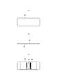
- the shape of the electronic tag 30 is generally a rectangular shape with rounded corners as shown in the examples shown in FIGS. 2 (a) to 2 (c), but the shape is not limited to this and may be an appropriate shape. it can.
- one of the typical electronic tags 30 is, for example, as shown in FIG. 2C, a passive type electronic tag 30 having an IC chip 30i as inlets 30a and 30i and an antenna 30a connected thereto. However, it is not limited to this.
- the attachment position of the electronic tag 30 (installation position of the tag attachment device 40) is a place where the work is conveyed between the corrugated cardboard sheet forming portion 10 and the product stacker 26 and along the surface to be the outer surface of the box. It is not particularly limited. For example (A) Near the entrance, inside, or exit of the printing machine 21 or slotter 23, (B) Before applying the adhesive in the folder gluer 25, after applying the adhesive and before folding, after the folding process, or after joining the joint, or (c) near the entrance of the product stacker 26.
- the electronic tag 30 can be attached by such means.
- the tag affixing device 40 can be a known industrial robot such as a parallel link robot, a vertical articulated robot, a horizontal articulated robot, or a Cartesian robot.
- a parallel link robot such as a parallel link robot, a vertical articulated robot, a horizontal articulated robot, or a Cartesian robot.
- the corrugated cardboard box manufacturing system there are many places where the work is transported in the direction along the outer surface of the box (for example, the corrugated cardboard sheet or the box blank 24p is laid down in the MD direction), and the posture is such that.
- It is preferable to attach the electronic tag 30 to the work that is stably conveyed because the device can be simplified, the manufacturing speed can be increased, the attachment can be stabilized, and the like.
- the tag affixing device 40 to which the labeler is applied can be preferably used.
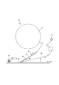
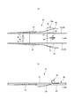
- the tag attaching device 40 shown in FIG. 3 is an example of one suitable for attaching the electronic tag 30 to the work 50 conveyed in the direction along the outer surface of the box, and is used by attaching the tag roll 41.
- the tag roll 41 is a continuous strip-shaped tag sheet 42 wound up in a roll shape, and the tag sheet 42 has an electronic tag 30 repeatedly attached at predetermined intervals in the continuous direction of the continuous strip-shaped release sheet 43. It is a thing.
- the tag roll 23R is rotatably supported by a rotation shaft (not shown), and the electronic tag 30 can be replenished or the type of the electronic tag 30 can be changed by replacing the tag roll 23R at any time.
- the tag sheet 42 unwound from the tag roll 41 is intermittently transferred at the timing of sticking to the work 50, and the folding guide 44 (a plate-shaped one as shown in the illustrated example, as well as a rotating shaft) is intermittently transferred. Or a non-rotating shaft).
- the folding guide 44 a plate-shaped one as shown in the illustrated example, as well as a rotating shaft
- the release sheet 43 is guided so as to be folded back to the side opposite to the side holding the electronic tag 30.
- the adhesive portion 31 of the rigid electronic tag 30 naturally peels off from the release sheet 43, and protrudes from the tip of the folding guide 44 toward the surface of the work 50 passing under the peeling guide 44, and the tip thereof. It is adhered to the surface of the work 50 in order from the beginning.
- an attachment roller 45 that presses the electronic tag 30 attached to the work 50 against the work 50 as shown in the illustrated example.
- it may have an air blowing device.
- the peeling sheet 43 remaining after the electronic tag 30 is peeled off is wound around the take-up shaft 46.
- the take-up shaft 46 is rotationally driven by a stepping motor (not shown) so that the electronic tags 30 are peeled off from the release sheet 43 one by one and attached to the work 50 at the timing of attachment to the work 50.
- winding is done intermittently.
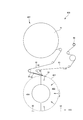
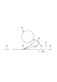
- a transfer roll 401 capable of adsorbing and releasing the electronic tag 30 on the outer peripheral surface and a tag supply for sequentially supplying the electronic tag 30 to the outer peripheral surface of the transfer roll 401.
- the work 50 is conveyed in the tangential direction of the outer peripheral surface of the transfer roll 401, including the device 402, and the electronic tag 30 adsorbed on the outer peripheral surface of the transfer roll 401 is released at a position in contact with the work 50 and transferred to the work 50.
- Things are also proposed. In the illustrated example, vent holes penetrating in the thickness direction are arranged at intervals over almost the entire outer peripheral wall of the transfer roll 401.
- the inner space of the transfer roll 401 is a vacuum suction chamber 403 provided in a range in the rotation direction from the receiving position of the electronic tag 30 to the sticking position with respect to the work 50, and the receiving position of the electronic tag 30 from the sticking position with respect to the work 50. It has a non-suction chamber 404 provided in the rotation direction range up to.
- the electronic tag 30 supplied from the tag supply device 402 is attracted to the outer peripheral surface of the transfer roll 401 by suction inside the transfer roll 401, and is attached to the work 50 by the rotation of the transfer roll 401.
- the electronic tag 30 that has reached the position is released from adsorption and is attached to the work 50 from the outer peripheral surface of the transfer roll 401.
- the transfer roll 401 may be, for example, a die cutter 24, a slotter 23, a printing roll, or the like.
- the transfer roll 401 is a print roll, the electronic tag 30 is not misaligned with respect to the print position.
- the tag feeding device 402 is not particularly limited. In the tag feeding device 402 shown in FIG. 4, the electronic tag 30 is turned face down (that is, the surface having no adhesive portion 31 is on the transfer roll 401 side) and the surface of the transfer roll 401. Since it is the same as the tag attaching device 40 shown in FIG.
- the timing of attaching the electronic tag 30 to the work 50 can be appropriately determined. However, since there is some deviation in the transfer timing of the work 50 in the blank forming portion 20B or the assembly portion (folder glue 25 in the illustrated example), the electronic tag 30 is attached to such a work 50 at a constant timing. In this case, the sticking position in the MD direction is deviated. Such a positional deviation in the MD direction itself is not unacceptable, but for example, as described above, when the printing machine 21 that prints on the outer surface of the box of the work 50 is provided, it is compared with the printing position. There is a risk that the sticking deviation of the electronic tag 30 will be noticeable, and there is a risk that the printing and the electronic tag 30 will overlap depending on the printing position. Therefore, as shown in FIG.
- a work sensor 47 (not shown) that detects the position of the work 50 to be transported (for example, the position of the end on the downstream side in the transport direction) on the upstream side of the sticking position by the tag sticking device 40 is provided. It is preferable that the electronic tag 30 is attached by the tag affixing device at the affixing timing determined according to the detection timing thereof to prevent the attachment position of the work 50 from being displaced in the MD direction.
- a known non-contact type sensor such as a transmission type sensor or a reflection type sensor, or a known contact type sensor can also be used.
- the detection position (installation position) of the work sensor 47 can be appropriately determined. For example, when the electronic tag 30 is attached at the folding portion of the folder gluer 25, the transport start position of the box blank 24p and the attachment position of the electronic tag 30 are attached. Can be between.
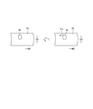
- the corrugated board sheet is warped due to the difference in moisture and tension between the upper and lower liners (upward warp, downward warp, S-shaped warp, twist (twist) warp, etc., JCS (corrugated cardboard industry standard) T0003-2000 corrugated cardboard warp. Refer to the measurement method.) Occurs. Therefore, when the electronic tag 30 is attached to the outer surface of the corrugated cardboard box in the corrugated cardboard box manufacturing system, the warp of the corrugated cardboard sheet affects the attachment deviation as described below, which in turn affects the damage of the electronic tag 30. There is a risk of That is, as shown in the right figure of FIG.
- the work 50 having a warp on the sticking surface (in the illustrated example, both ends in the CD direction are raised toward the front side of the drawing from the center) is moving in the MD direction.
- the adhesive portion 31 of the electronic tag 30 is brought into contact with the sticking surface, the portion 31c of the adhesive portion 31 of the electronic tag 30 closest to the sticking surface adheres first, and the remaining portion adheres with a delay. become.
- the adhesive timing is different in the CD direction, the earliest adhesive portion 31c of the electronic tag 30 starts to move first together with the work 50 as shown by the arrow, and the remaining portion is delayed from this.
- the electronic tag 30 may be attached diagonally as shown in the left figure.
- the electronic tag 30 has an IC chip 30i and an antenna 30a conductively connected to the IC chip 30i, and when an unexpected force is applied to the connection portion between the IC chip 30i and the antenna 30a, the connection portion is peeled off. Poor continuity may occur. That is, as described above, in a situation where the portion of the adhesive portion 31 of the electronic tag 30 that is closest to the attachment surface adheres first and the remaining portion adheres later, the connection portion between the IC chip 30i and the antenna 30a. A force that twists the electronic tag 30 acts from the start to the completion of adhesion, and the force tends to concentrate on the connection portion between the IC chip 30i and the antenna 30a. Therefore, the connection between the IC chip 30i and the antenna 30a It may cause peeling of the part.
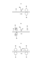
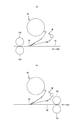
- a straightening roller 48 that comes into contact with the sticking surface of the electronic tag 30 and the opposite surface of the work 50 to correct the warp of the sticking surface at the sticking position 50p of the electronic tag 30.
- FIG. 7B wind pressure is applied (air is blown) to the sticking surface of the electronic tag 30 and the opposite surface of the work 50 to correct the warp of the sticking surface at the sticking position 50p of the electronic tag 30.
- a wind pressure correction device 49 may be provided.
- the wind pressure correction device 49 a blower (blower fan) or a compressed air injection device can be used, which is preferable in that it is non-contact, that is, it has little effect on the surface of the corrugated cardboard sheet and can correct warpage. ..
- the warp measuring sensor 60 for example, the distance sensor for measuring the distance to the sticking surface of the work 50
- the wind pressure correction device 49 is used, the warp measuring sensor 60 (for example, the distance sensor for measuring the distance to the sticking surface of the work 50) is appropriately spaced in the CD direction to measure the warp at the sticking position 50p of the electronic tag 30 and its vicinity.
- the warp correcting means 48, 49 are near the upstream side (FIG. 7 (a)) and the downstream side (FIG. 7 (a)) of the sticking position of the electronic tag 30 in the MD direction as long as the warp of the sticking surface of the electronic tag 30 in the work 50 can be corrected. 7 (b)) or both (FIG. 7 (c)) may be provided. Further, the contact position of the straightening roller 48 and the blowing position of the wind pressure straightening device 49 are only the portion through which the sticking position of the electronic tag 30 passes in the CD direction (FIG. 8 (b)), or a wide range including this (for example, FIG.
- the contact surface of the straightening roller 48 and the spraying surface of the wind pressure straightening device 49 may be only one of the sticking surface of the electronic tag 30 on the work 50 and the opposite surface thereof.
- the tag sticking device 40 is supported via the attitude control device so that the posture of the tag sticking device 40 can be changed at least in the CD direction (preferably in all directions), and the sticking position of the electronic tag 30 and its sticking position thereof.
- a warp measuring sensor 60 for measuring warpage in the vicinity is provided so that the bonding start position of the adhesive portion 31 of the electronic tag 30 and the sticking surface of the electronic tag 30 on the work 50 are parallel according to the measurement result.
- the attitude of the tag affixing device 40 may be controlled. Such attitude control can be used in place of or with the warp correction means 48, 49.
- a wind pressure pressing device 70 that applies wind pressure according to the transport speed of the work 50 is installed on the surface of the electronic tag 30 at the sticking position on the side opposite to the side having the adhesive portion 31, and the work 50 is installed. It is preferable to reduce the influence of the wind generated by the transportation of the wind.
- a database for storing the transport speed of the work 50 or the wind pressure data for canceling the influence of the wind generated according to the work 50 and the transport speed is provided in the main body, and the database is provided in the main body according to the operating status of the system. It is convenient to automatically control the wind pressure of the wind pressure pressing device 70 using the values in this database. The result of this wind pressure control may be sampled as appropriate, and if there is a deviation, the value in the database may be corrected.
- the wind pressure pressing device 70 can be used in place of or in combination with the warp correction means 48, 49.
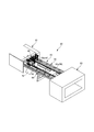
- the folder gluer 25 of this example has a general configuration having a blank supply portion 81 for supplying a box blank 24p to the folding portion 82, a folding portion 82, and a joint joint portion 83 for crimping and joining the joint portions. is there.
- the blank supply unit 81 glues the box blank 24p to the joint portion located at one end in the CD direction by a gluing device (not shown) in the process of feeding the box blank 24p to the folding portion 82.
- the folding portion 82 of this example is a pair of sandwiching and transporting devices 90 spaced in the CD direction, sandwiching the non-folding portion nf of the box blank 24p in the thickness direction and transporting in the MD direction, while being transported from the pair of sandwiching and transporting devices 90. Also, the folded portion fp of the box blank 24p passing outside in the CD direction is folded toward the center side in the CD direction.
- the pinching transfer device 90 sandwiches a box blank 24p between the upper endless belt 91 and the lower endless belts 92 and 93 in contact with the lower surface thereof.
- the ruled line of the box blank 24p that is folded by the folding portion 82 is located near the outside of the holding and conveying device 90 in the CD direction, and the folded portion fp of the box blank 24p that is outside the ruled line in the CD direction is formed by the guide device. It is folded to the lower side and the center side in the CD direction.
- the configuration of the guide device is not particularly limited.
- the upper endless belt 91 extends over the entire MD direction of the folding portion 82, while the lower endless belts 92 and 93 are on the downstream side with the first lower endless belt 92 located on the upstream side in the MD direction. It has a second lower endless belt 93 that is located.
- a guide bar extending in a curved shape so as to gradually enter the lower side of the sandwich transfer device 90 from the outside in the CD direction to the downstream side in the MD direction of the sandwich transfer device 90.
- a 94 is provided, and the folded portion of the box blank 24p is first brought into contact with the guide bar 94 and bent by about 90 degrees.
- the transport surface of the second lower endless belt 93 gradually becomes the upper endless belt 91 from the outside of the folded portion of the box blank 24p in the CD direction to the downstream side in the MD direction.
- the folded portion of the box blank 24p which is guided to enter the lower side and is bent to about 90 degrees, is then brought into contact with the second lower endless belt 93 and bent to the final state.
- the guide device of this example is composed of the guide bar 94 and the second lower endless belt 93. It is known that the entire guide device is composed of lower endless belts 92 and 93, or the folding direction is turned upside down, but these known changes can also be adopted.
- the sticking position in the CD direction is not particularly limited, but as shown in the illustrated example, the tag sticking device 90 is sandwiched between the pair of sandwiching transport devices 90 in the box blank 24p. If the electronic tag 30 is attached to the non-folding portion nf through which the tag is passed, not only the tag attaching device 40 can be easily installed, but also the transport posture of the box blank 24p is stable, so that the electronic tag 30 can be easily attached. Is. Further, as described above, in order to reduce the influence of the warp of the work 50, a tag is attached to a portion where the warp is smaller, for example, the vicinity of the pinch transport device 90 or the central portion of the pair of pinch transport devices 90 in the CD direction. It is also preferable to set the attachment position of the device 40.
- the sticking position in the MD direction of the folding portion 82 can be appropriately determined, but a portion having less warpage, for example, a position before the folding of the box blank 24p is started or a position where the folding angle with respect to the horizontal direction is less than 45 degrees ( In the illustrated example), it is preferable to attach the electronic tag 30.
- the folding unit 82 adjusts the distance between the pair of holding and transporting devices 90 in the CD direction according to the size change of the corrugated cardboard box, so that the pair of frames 95 that support the pair of holding and transporting devices 90 are spaced apart from each other in the CD direction. Is adjustable.
- the tag attaching device 40 is supported by each of the pair of frames 95 via a telescopic frame 96 that can be expanded and contracted in the CD direction, and is adjusted.
- the telescopic frame 96 expands and contracts accordingly, and the position of the tag affixing device 40 is maintained. At this time, it is preferable because the installation position adjustment of the tag affixing device 40 is unnecessary or simple.
- the tag attaching device 40 is attached to the folding portion 82 via a vibration absorbing elastic body such as rubber or a spring, or a vibration absorbing device such as oil pressure or air. It is preferable to have it.
- the tag attaching device 40 When the tag attaching device 40 is installed in addition to the folding portion 82, as shown in FIG. 13, in a device having a pair of rolls 100 that sandwich the entire CD direction of the work 50 to be conveyed in the thickness direction, the pair of rolls 100 It is preferable to install the tag affixing device 40 so that the electronic tag 30 is affixed to the work 50 in the sandwiched state. That is, when the work 50 is sandwiched between a pair of rolls 100 such as a die cutter 24, a slotter 23, a printing roll, etc., which sandwich the entire CD direction of the work 50 in the thickness direction, the posture of the work 50 is not only stabilized but also warped. Therefore, if the electronic tag 30 is attached in this state, the electronic tag 30 can be attached at a higher speed and more stably.
- a pair of rolls 100 such as a die cutter 24, a slotter 23, a printing roll, etc.
- the present invention can be used in a manufacturing system for a corrugated cardboard box with an electronic tag to which an electronic tag having an adhesive portion is attached.
Landscapes
- Engineering & Computer Science (AREA)
- Mechanical Engineering (AREA)
- Making Paper Articles (AREA)
- Labeling Devices (AREA)
Priority Applications (1)
| Application Number | Priority Date | Filing Date | Title |
|---|---|---|---|
| US17/639,629 US12037157B2 (en) | 2019-09-06 | 2020-09-04 | System for manufacturing cardboard box with electronic tag and method therefor |
Applications Claiming Priority (2)
| Application Number | Priority Date | Filing Date | Title |
|---|---|---|---|
| JP2019-163374 | 2019-09-06 | ||
| JP2019163374A JP7440231B2 (ja) | 2019-09-06 | 2019-09-06 | 電子タグ付き段ボール箱の製造システム及びその方法 |
Publications (1)
| Publication Number | Publication Date |
|---|---|
| WO2021045208A1 true WO2021045208A1 (ja) | 2021-03-11 |
Family
ID=74853345
Family Applications (1)
| Application Number | Title | Priority Date | Filing Date |
|---|---|---|---|
| PCT/JP2020/033651 Ceased WO2021045208A1 (ja) | 2019-09-06 | 2020-09-04 | 電子タグ付き段ボール箱の製造システム及びその方法 |
Country Status (4)
| Country | Link |
|---|---|
| US (1) | US12037157B2 (cg-RX-API-DMAC10.html) |
| JP (1) | JP7440231B2 (cg-RX-API-DMAC10.html) |
| TW (1) | TW202128412A (cg-RX-API-DMAC10.html) |
| WO (1) | WO2021045208A1 (cg-RX-API-DMAC10.html) |
Families Citing this family (2)
| Publication number | Priority date | Publication date | Assignee | Title |
|---|---|---|---|---|
| US12214925B2 (en) * | 2022-10-21 | 2025-02-04 | Westrock Shared Services, Llc | Methods and machine for forming a container from a blank and applying an identification tag |
| CN116812299A (zh) * | 2023-07-24 | 2023-09-29 | 深圳市天亮环保科技有限公司 | 一种可进行校准的包装盒标签张贴工艺 |
Citations (4)
| Publication number | Priority date | Publication date | Assignee | Title |
|---|---|---|---|---|
| JPS4640676B1 (cg-RX-API-DMAC10.html) * | 1968-05-06 | 1971-12-01 | ||
| JPS58139414U (ja) * | 1982-03-15 | 1983-09-20 | 株式会社寺岡精工 | ラベル貼付装置 |
| JP2011201579A (ja) * | 2010-03-26 | 2011-10-13 | Sato Knowledge & Intellectual Property Institute | 板状部材のラベル貼付システム |
| JP2018538181A (ja) * | 2015-12-23 | 2018-12-27 | オーワイ ヨパマック エービー | 包装箱を形成するための方法および装置 |
Family Cites Families (12)
| Publication number | Priority date | Publication date | Assignee | Title |
|---|---|---|---|---|
| JP3770640B2 (ja) * | 1995-11-24 | 2006-04-26 | 株式会社サトー | ラベルテープの切断・移送装置 |
| JP2004075075A (ja) | 2002-08-09 | 2004-03-11 | Fuji Seal Inc | 折畳ケース及び折畳ケースの製造方法 |
| US7436305B2 (en) * | 2005-07-19 | 2008-10-14 | Checkpoint Systems, Inc. | RFID tags for pallets and cartons and system for attaching same |
| JP2007145419A (ja) | 2005-11-24 | 2007-06-14 | Fuji Xynetics Kk | 段ボールシートのicタグ装着システム |
| US7605708B2 (en) * | 2005-12-22 | 2009-10-20 | Checkpoint Systems, Inc. | Smart corrugated cardboard |
| DE102006007290B3 (de) * | 2006-02-16 | 2007-11-22 | Texmag Gmbh Vertriebsgesellschaft Gmbh | Verfahren zur Einbringung von RFID-Tags in Wellpappe und Materialstück aus Pappe mit RFID-Tag |
| JP5173341B2 (ja) | 2007-09-26 | 2013-04-03 | 三菱重工印刷紙工機械株式会社 | 製函機の不良品除去装置および製函機 |
| JP2010137915A (ja) | 2008-12-12 | 2010-06-24 | Kazuo Yanaida | 簡易液体商品充填装置 |
| JP5848000B2 (ja) | 2010-09-30 | 2016-01-27 | 三菱重工印刷紙工機械株式会社 | 製函機の不良品除去装置及び製函機 |
| JP5804755B2 (ja) | 2011-04-14 | 2015-11-04 | サトーホールディングス株式会社 | 板状部材のラベル貼付システム |
| JP6171203B2 (ja) | 2011-09-09 | 2017-08-02 | 株式会社フジシール | ラベル貼付装置 |
| JP6484379B1 (ja) | 2018-10-15 | 2019-03-13 | 大王製紙株式会社 | 電子タグの貼付装置及びその方法 |
-
2019
- 2019-09-06 JP JP2019163374A patent/JP7440231B2/ja active Active
-
2020
- 2020-09-04 US US17/639,629 patent/US12037157B2/en active Active
- 2020-09-04 TW TW109130321A patent/TW202128412A/zh unknown
- 2020-09-04 WO PCT/JP2020/033651 patent/WO2021045208A1/ja not_active Ceased
Patent Citations (4)
| Publication number | Priority date | Publication date | Assignee | Title |
|---|---|---|---|---|
| JPS4640676B1 (cg-RX-API-DMAC10.html) * | 1968-05-06 | 1971-12-01 | ||
| JPS58139414U (ja) * | 1982-03-15 | 1983-09-20 | 株式会社寺岡精工 | ラベル貼付装置 |
| JP2011201579A (ja) * | 2010-03-26 | 2011-10-13 | Sato Knowledge & Intellectual Property Institute | 板状部材のラベル貼付システム |
| JP2018538181A (ja) * | 2015-12-23 | 2018-12-27 | オーワイ ヨパマック エービー | 包装箱を形成するための方法および装置 |
Also Published As
| Publication number | Publication date |
|---|---|
| TW202128412A (zh) | 2021-08-01 |
| US20220289419A1 (en) | 2022-09-15 |
| JP7440231B2 (ja) | 2024-02-28 |
| US12037157B2 (en) | 2024-07-16 |
| JP2021041941A (ja) | 2021-03-18 |
Similar Documents
| Publication | Publication Date | Title |
|---|---|---|
| JP6990789B2 (ja) | 連続段ボールシートの製造方法及び段ボールシート製造装置 | |
| US8870174B2 (en) | Machine for producing books, in particular photo books and/or illustrated books | |
| JP4805778B2 (ja) | 包装方法及び装置 | |
| US11833774B2 (en) | Dimensionally variable lid manufacturing method and dimensionally variable lid manufacturing device | |
| JP2017035755A (ja) | 段ボールシートの切断装置及びその切断制御装置並びに段ボールシートの製造装置 | |
| CN1422412A (zh) | 用于生产装有集成转发器的数据载体的方法和设备 | |
| JP2002145266A (ja) | 平版印刷版積載用パレット構造 | |
| US20180215061A1 (en) | Corrugated cardboard plant | |
| WO2018074362A1 (ja) | シート折り畳み装置及び製函機 | |
| JP7440231B2 (ja) | 電子タグ付き段ボール箱の製造システム及びその方法 | |
| US9017240B2 (en) | Transporting apparatus and sheet-processing machine with a transporting apparatus | |
| JP2021041941A5 (cg-RX-API-DMAC10.html) | ||
| JP7264702B2 (ja) | 寸法可変の箱ブランク製造装置、寸法可変の箱ブランク製造方法、箱ブランクの組み立て方法、および寸法可変の自動包装ライン | |
| JP2018538181A (ja) | 包装箱を形成するための方法および装置 | |
| JP4623632B2 (ja) | 筒状フィルムの製造装置 | |
| US9358769B2 (en) | Method for manufacturing a multi-layer composite, arrangement for positioning a sheet-like element onto a backing in a laminating unit | |
| JP2003154583A (ja) | 段ボールの糊付け装置及び製造システム | |
| JP3610062B2 (ja) | フォルダー・グルア用供給・整合装置 | |
| CN224183907U (zh) | 封面纸处理装置 | |
| JP2007030178A (ja) | 段ボールシートの製造装置 | |
| CN118679054A (zh) | 借助订单更改检测器制造瓦楞板的设备和方法 | |
| JPH0687176A (ja) | 段ボールシートの折畳み装置 | |
| JP3123941U (ja) | Icタグ付テープの製造装置および目印付きicタグ付テープ | |
| JP2005022350A (ja) | シートの貼合方法および貼合装置 | |
| JP2007261048A (ja) | 製本装置 |
Legal Events
| Date | Code | Title | Description |
|---|---|---|---|
| 121 | Ep: the epo has been informed by wipo that ep was designated in this application |
Ref document number: 20860456 Country of ref document: EP Kind code of ref document: A1 |
|
| NENP | Non-entry into the national phase |
Ref country code: DE |
|
| 122 | Ep: pct application non-entry in european phase |
Ref document number: 20860456 Country of ref document: EP Kind code of ref document: A1 |