WO2021039179A1 - 磁気クランプ装置 - Google Patents
磁気クランプ装置 Download PDFInfo
- Publication number
- WO2021039179A1 WO2021039179A1 PCT/JP2020/027620 JP2020027620W WO2021039179A1 WO 2021039179 A1 WO2021039179 A1 WO 2021039179A1 JP 2020027620 W JP2020027620 W JP 2020027620W WO 2021039179 A1 WO2021039179 A1 WO 2021039179A1
- Authority
- WO
- WIPO (PCT)
- Prior art keywords
- magnetic
- magnetic pole
- magnet
- plate body
- cavity
- Prior art date
Links
- 230000005291 magnetic effect Effects 0.000 title claims abstract description 197
- 230000002093 peripheral effect Effects 0.000 claims description 29
- 230000002441 reversible effect Effects 0.000 claims description 21
- 239000003566 sealing material Substances 0.000 claims description 15
- 239000000696 magnetic material Substances 0.000 claims description 7
- 230000002427 irreversible effect Effects 0.000 claims description 5
- 238000007789 sealing Methods 0.000 claims description 4
- 229910000828 alnico Inorganic materials 0.000 abstract description 44
- 229910001172 neodymium magnet Inorganic materials 0.000 description 26
- 230000004907 flux Effects 0.000 description 10
- 238000010586 diagram Methods 0.000 description 6
- 238000000034 method Methods 0.000 description 4
- 239000003795 chemical substances by application Substances 0.000 description 2
- 239000000498 cooling water Substances 0.000 description 2
- 238000001746 injection moulding Methods 0.000 description 2
- 239000007788 liquid Substances 0.000 description 2
- 238000012423 maintenance Methods 0.000 description 2
- 230000000149 penetrating effect Effects 0.000 description 2
- 229910001369 Brass Inorganic materials 0.000 description 1
- 229910000831 Steel Inorganic materials 0.000 description 1
- 238000013459 approach Methods 0.000 description 1
- 239000010951 brass Substances 0.000 description 1
- 238000005260 corrosion Methods 0.000 description 1
- 230000007797 corrosion Effects 0.000 description 1
- 239000003302 ferromagnetic material Substances 0.000 description 1
- 238000005498 polishing Methods 0.000 description 1
- 239000010959 steel Substances 0.000 description 1
- 229920003002 synthetic resin Polymers 0.000 description 1
- 239000000057 synthetic resin Substances 0.000 description 1
- XLYOFNOQVPJJNP-UHFFFAOYSA-N water Substances O XLYOFNOQVPJJNP-UHFFFAOYSA-N 0.000 description 1
Images


Classifications
-
- H—ELECTRICITY
- H01—ELECTRIC ELEMENTS
- H01F—MAGNETS; INDUCTANCES; TRANSFORMERS; SELECTION OF MATERIALS FOR THEIR MAGNETIC PROPERTIES
- H01F7/00—Magnets
- H01F7/02—Permanent magnets [PM]
- H01F7/04—Means for releasing the attractive force
-
- B—PERFORMING OPERATIONS; TRANSPORTING
- B23—MACHINE TOOLS; METAL-WORKING NOT OTHERWISE PROVIDED FOR
- B23Q—DETAILS, COMPONENTS, OR ACCESSORIES FOR MACHINE TOOLS, e.g. ARRANGEMENTS FOR COPYING OR CONTROLLING; MACHINE TOOLS IN GENERAL CHARACTERISED BY THE CONSTRUCTION OF PARTICULAR DETAILS OR COMPONENTS; COMBINATIONS OR ASSOCIATIONS OF METAL-WORKING MACHINES, NOT DIRECTED TO A PARTICULAR RESULT
- B23Q3/00—Devices holding, supporting, or positioning work or tools, of a kind normally removable from the machine
- B23Q3/15—Devices for holding work using magnetic or electric force acting directly on the work
- B23Q3/154—Stationary devices
- B23Q3/1546—Stationary devices using permanent magnets
-
- B—PERFORMING OPERATIONS; TRANSPORTING
- B29—WORKING OF PLASTICS; WORKING OF SUBSTANCES IN A PLASTIC STATE IN GENERAL
- B29C—SHAPING OR JOINING OF PLASTICS; SHAPING OF MATERIAL IN A PLASTIC STATE, NOT OTHERWISE PROVIDED FOR; AFTER-TREATMENT OF THE SHAPED PRODUCTS, e.g. REPAIRING
- B29C33/00—Moulds or cores; Details thereof or accessories therefor
- B29C33/30—Mounting, exchanging or centering
- B29C33/32—Mounting, exchanging or centering using magnetic means
-
- B—PERFORMING OPERATIONS; TRANSPORTING
- B29—WORKING OF PLASTICS; WORKING OF SUBSTANCES IN A PLASTIC STATE IN GENERAL
- B29C—SHAPING OR JOINING OF PLASTICS; SHAPING OF MATERIAL IN A PLASTIC STATE, NOT OTHERWISE PROVIDED FOR; AFTER-TREATMENT OF THE SHAPED PRODUCTS, e.g. REPAIRING
- B29C45/00—Injection moulding, i.e. forcing the required volume of moulding material through a nozzle into a closed mould; Apparatus therefor
- B29C45/17—Component parts, details or accessories; Auxiliary operations
- B29C45/1742—Mounting of moulds; Mould supports
- B29C45/1744—Mould support platens
-
- F—MECHANICAL ENGINEERING; LIGHTING; HEATING; WEAPONS; BLASTING
- F16—ENGINEERING ELEMENTS AND UNITS; GENERAL MEASURES FOR PRODUCING AND MAINTAINING EFFECTIVE FUNCTIONING OF MACHINES OR INSTALLATIONS; THERMAL INSULATION IN GENERAL
- F16B—DEVICES FOR FASTENING OR SECURING CONSTRUCTIONAL ELEMENTS OR MACHINE PARTS TOGETHER, e.g. NAILS, BOLTS, CIRCLIPS, CLAMPS, CLIPS OR WEDGES; JOINTS OR JOINTING
- F16B2/00—Friction-grip releasable fastenings
- F16B2/02—Clamps, i.e. with gripping action effected by positive means other than the inherent resistance to deformation of the material of the fastening
- F16B2/06—Clamps, i.e. with gripping action effected by positive means other than the inherent resistance to deformation of the material of the fastening external, i.e. with contracting action
-
- H—ELECTRICITY
- H01—ELECTRIC ELEMENTS
- H01F—MAGNETS; INDUCTANCES; TRANSFORMERS; SELECTION OF MATERIALS FOR THEIR MAGNETIC PROPERTIES
- H01F7/00—Magnets
-
- B—PERFORMING OPERATIONS; TRANSPORTING
- B29—WORKING OF PLASTICS; WORKING OF SUBSTANCES IN A PLASTIC STATE IN GENERAL
- B29C—SHAPING OR JOINING OF PLASTICS; SHAPING OF MATERIAL IN A PLASTIC STATE, NOT OTHERWISE PROVIDED FOR; AFTER-TREATMENT OF THE SHAPED PRODUCTS, e.g. REPAIRING
- B29C45/00—Injection moulding, i.e. forcing the required volume of moulding material through a nozzle into a closed mould; Apparatus therefor
- B29C45/17—Component parts, details or accessories; Auxiliary operations
- B29C45/1742—Mounting of moulds; Mould supports
- B29C2045/1746—Mounting of moulds; Mould supports using magnetic means
Definitions
- the present invention relates to a magnetic clamp device having a disassembled structure that is easy to maintain.
- a magnetic clamp device that utilizes magnetic attraction is known for fixing molds in injection molding machines.
- the magnetic clamp device is a technique for attaching a magnetic plate body to a platen of an injection molding machine and magnetically fixing a mold.
- a plurality of magnetic pads are provided on the plate body.
- Each magnetic pad has a non-reversible magnet (eg, a neodymium magnet) provided around the magnetic pole and a reversible magnet (eg, an alnico magnet) located behind the magnetic pole.
- a non-reversible magnet eg, a neodymium magnet
- a reversible magnet eg, an alnico magnet
- the magnetic clamping device is generally cooled by cooling water until the molded product inside the mold is cooled and cured while the mold is still clamped, and the cooling water is inside the magnetic clamping device.
- the magnetic clamping device employs a liquid-tight structure in order to prevent corrosion and short circuit of the coil and the like due to intrusion.
- a non-magnetic ring made of brass is arranged on the outer peripheral surface of the magnetic pole, and a liquid is provided by providing an outer peripheral groove for receiving an O-ring on the outer peripheral surface of the ring.
- a magnetic clamping device having tightness is disclosed.
- the outer peripheral edge portion of the magnetic pole and the inner peripheral portion of the non-magnetic annular body are screwed and fitted in a male screw / female screw relationship, and are sealed in the fitting portion.
- a magnetic clamping device to which the agent is arranged is disclosed.
- the liquidtightness of the electric system such as the coil inside the plate body of the magnetic clamping device can be improved by the O-ring or the sealing agent, but water for a long period of time can be improved.
- the intrusion cannot be completely eliminated, and it is expected that someday maintenance of the inside of the magnetic clamping device will be required.
- a central fastening hole central hole
- a bolt screw
- a bolt penetrates the plate body and the alnico magnet from the plate body side through the fastening hole and is screwed to the magnetic pole.
- Patent Document 1 and Patent Document 2 it is possible to mechanically separate the magnetic pole from the alnico magnet and the plate body by removing the respective bolts.
- the magnetic force of the neodymium magnet is extremely strong, and it is not easy to peel off the magnetic pole from the plate body.
- the magnetic clamp devices of Patent Documents 1 and 2 require a special tool that pushes a magnetic pole and an alnico magnet from the back side of the plate body to the front side of the plate body against the force of the neodymium magnet.
- paragraph 0067 of Patent Document 2 when an extra gap is filled with a sealing material made of synthetic resin as needed, it becomes more difficult to extrude.
- An object of the present invention is to provide a magnetic clamp device having a disassembled structure that is easy to maintain.
- a plate body made of a magnetic material having a bottomed cavity on the surface and a magnetic pad arranged in the cavity, which are a magnetic pole, the magnetic pole, and the cavity.
- a magnetic pad having a reversible magnet provided between the bottom surface and a reversible magnet provided between the magnetic pole and the irreversible magnet provided between the magnetic pole and the side surface of the inner circumference of the cavity is provided.
- the magnetic pole and the reversible magnet each have a fastening hole that communicates with each other, and the cavity has an opening that penetrates from the bottom surface to the back side of the plate body.
- a cap having a base portion having a bolt hole communicating with the fastening hole and a flange portion having a contact surface in contact with the back surface of the plate is inserted. Then, a bolt inserted into the fastening hole of the magnetic pole and the reversible magnet from the front side of the magnetic pad is screwed into or screwed into a female screw thread provided in the bolt hole of the cap. The bolt hole is penetrated through the back side of the plate body, and a bolt inserted into the fastening hole of the bolt hole and the reversible magnet from the flange side of the cap is provided in the fastening hole of the magnetic pole. It is screwed against the screw thread.
- the tool bolt when the cap is removed from the opening and the tool bolt is screwed into the female thread of the opening, the tool bolt abuts on the alnico magnet.
- the alnico magnet and the magnetic pole are peeled off from the plate body. In this way, it can be easily peeled off with one tool bolt.
- FIG. 1A is a view showing a magnetic clamp device
- FIG. 1A is a view of the magnetic clamp device from the front side
- FIG. 1B is a cross-sectional view of one magnetic pad
- FIG. 1C is an exploded view
- 2A and 2B are views showing the action
- FIG. 2A is a view before peeling
- FIG. 2B is a view after peeling
- 3A and 3B are views of another embodiment
- FIG. 3A is a cross-sectional view
- FIG. 3B is a view before peeling
- FIG. 3C is a view after peeling
- FIG. 4 is a view of the third embodiment
- FIG. 4A is a cross-sectional view
- FIG. 4B is a view after peeling.
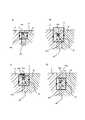
- FIG. 5A and 5B are views showing a modified portion of the third embodiment, FIG. 5A is a partially enlarged view, and FIG. 5B is a view showing a plurality of magnetic poles. It is a figure which shows the magnetic flux of the outer peripheral part of the magnetic pole when the magnetic clamp device is deactivated, FIG. 6A is Example 1 and Example 2, FIG. 6B and FIG. 6C are Example 3, and FIG. 6D is Example. The magnetic flux of the outer peripheral portion of 4 is shown.
- FIG. 1 is a diagram showing a magnetic clamp device 1.
- 1A is a front view of the magnetic clamp device 1
- FIG. 1B is a cross-sectional view of one magnetic pad 2
- FIG. 1C is an exploded view of the magnetic pad 2.
- the magnetic clamp device 1 has a plate body 3 made of a magnetic material and a large number of magnetic pads 2 arranged in a bottomed cavity 31 provided on the surface of the plate body 3.
- the surface of the plate body 3 is also provided with a proximity sensor 4, a through hole 5 into which an ejector rod (not shown) is inserted, and the like.
- the circular dotted line in the figure indicates a space (wiring chamber 32) provided on the back side of the plate main body 3.
- the wiring chamber 32 is arranged so as to partially overlap the adjacent cavity portions 31 in a plan view, and necessary cables are connected.
- the magnetic pad 2 has a cylindrical shape (hereinafter, the center of the magnetic pad 2 is referred to as a central axis c), and the magnetic pole 21 and the polar inversion provided around the magnetic pole 21 cannot be reversed.
- a magnet non-reversible magnet, for example, neodymium magnet 22
- a polarity reversible magnet reversible magnet, for example, Arnico magnet 23
- It has a magnet 24 and a coil 25 wound around the magnet 24.
- the magnetic pole 21 is made of a ferromagnetic material such as steel.
- the magnetic pole 21 and the alnico magnet 23 each have fastening holes 21a and 23a along the central axis c, and the fastening holes 21a and 23a communicate with each other.
- the bolt 8 is inserted from the front side of the plate body 3 (the side that clamps the mold, the upper side in the drawing) so that the bolt 8 can be penetrated.
- the fastening holes 21a and 23a are through holes without threads.
- the magnetic pole 21 is provided with a neodymium magnet 22 along the wall of the side surface 21b on the outer periphery thereof.
- the neodymium magnet 22 is polarized in the radial direction of the magnetic pole 21.
- the neodymium magnet 22 is divided into a plurality of parts in the circumferential direction, and one piece thereof has an arc shape.
- the neodymium magnet 22 is formed as little as possible between the inner peripheral side surface 31a of the cavity 31 and the outer peripheral side surface 21b of the magnetic pole 21. Placed in.
- the alnico magnet 23 is arranged on the back side of the magnetic pole 21.
- the coil 25 wound around the alnico magnet 23 forms a magnet whose magnetic polarity can be switched by the alnico magnet 23.
- the alnico magnet 23 is arranged between the bottom surface 31b of the cavity 31 and the bottom surface 21d of the magnetic pole 21.
- a part of the cavity 31 of the plate body 3 communicates with the wiring chamber 32.
- the terminal 25a of the coil 25 of the magnetic pad 2 appears in the wiring chamber 32 by utilizing this communicated portion.
- the connection 26 is made to the terminal 25a of the coil 25 so that a required control current can be supplied.
- the wiring chamber 32 is also used for connecting other electric circuits such as the proximity sensor 4 (not shown).
- a lid 6 is attached to the wiring chamber 32 so that the wiring chamber 32 can be closed from the back side of the plate body 3. Further, the lid 6 is attached to the plate body 3 via the gasket 61 in order to prevent the liquid from entering from the periphery of the wiring chamber 32 of the plate body 3 and to ensure the liquidtightness.
- the bottom surface 31b of the cavity 31 facing the magnetic pole 21 is provided with an opening 33 having a circular cross section that penetrates the back side of the plate body 3 along the central axis c.
- the diameter of the opening 33 is larger than the diameter of the fastening holes 21a and 23a.
- the base portion 71 of the cap 7 is inserted into the opening 33.
- the cap 7 is a magnetic material or a non-magnetic material, and has a base portion 71 having a circular cross section, an O-ring groove 73, and a flange portion 72 from the top of the drawing with the central axis c.
- a sealing material 75 (O-ring) that comes into contact with the inner circumference of the opening 33 is arranged in the O-ring groove 73.
- Bolt holes 74 are opened in the base portion 71 along the central axis c.
- the bolt holes 74 are non-penetrating, and when the base portion 71 is inserted into the opening 33, the bolt holes 74 communicate with the fastening holes 21a and 23a.
- a female thread 74a into which the bolt 8 is screwed is provided on the inner circumference of the bolt hole 74.
- the flange portion 72 is provided with a contact surface 72a that comes into contact with the surface 3b on the back side of the plate body 3.
- a widening portion 34 is provided at the entrance of the opening 33 in order to accommodate the collar portion 72 on the plate main body 3 side and reduce the unevenness on the back side of the plate main body 3.
- a female thread 33a is provided on the inner circumference of the opening 33 on the bottom surface 31b side of the cavity 31.
- the range of the inner circumference of the opening 33 provided with the female thread 33a is a part, and is limited to a range that does not interfere with the O-ring 75 of the O-ring groove 73.
- a male thread may be provided on the outer periphery of the base portion 71 of the cap 7 and screwed with the female thread 33a.
- a sealing material 75 (O-ring) is installed in the O-ring groove 73 to perform sealing with the inner circumference of the opening 33 with improved liquidtightness.
- the magnetic pole 21, the alnico magnet 23, the cap 7, and the surface 3b of the plate body 3 are fixed in the central axis c direction without an elastic body. Therefore, it is easy to make the surface surfaces 3a and 21c of the plate body 3 and the magnetic pole 21 on the front side uniform.
- the bolt 8 fixes the magnetic pole 21 via a sealing material 81 (seal washer).
- the magnetic clamp device 1 is in the operating state (magnetized state). Since the alnico magnet 23 does not have a relatively high coercive force as a permanent magnet, when the mold is momentarily separated, the magnetic force of the neodymium magnet 22 cancels the magnetic force of the alnico magnet 23 in whole or in part. The clamping force of the magnetic clamping device 1 is lost.
- the alnico magnet 23 By passing a current in the opposite direction from the outside to the coil 25 of the alnico magnet 23, the alnico magnet 23 generates a new magnetic field in the opposite direction. At this time, the magnetic clamping device 1 is switched to the non-operating state (demagnetized state), and the clamping force acting on the mold is lost.
- FIG. 2 is a diagram showing the operation of the embodiment
- FIG. 2A is a diagram before peeling
- FIG. 2B is a diagram after peeling.
- the lid 6 is opened and the connection 26 of the terminal 25a of the coil 25 is removed. Unscrew the bolt 8 and the cap 7.
- the tool bolt 10 is screwed into the female thread 33a of the opening 33
- the tool bolt 10 abuts on the alnico magnet 23.
- the tool bolt 10 peels off the alnico magnet 23 and the neodymium magnet 22 from the plate body 3 which is magnetically attracted. In this way, it can be easily peeled off with one tool bolt 10.
- the tool bolt 10 may be a bolt made for peeling, or may be a commercially available general bolt of JIS standard or inch standard. It is preferable to set the female thread 33a of the opening 33 so that a general bolt can also be used as the tool bolt 10.
- the neodymium magnet 22 is attracted to the magnetic pole 21 side and comes out from the cavity 31 of the plate body 3. This is because a slight protrusion 21f is provided between the bobbin 24 and the neodymium magnet 22 from the side surface 21b of the magnetic pole 21, and the neodymium magnet 22 is lifted by being guided by the movement of the magnetic pole 21.
- the bobbin 24 since the bobbin 24 has a size in the radial direction larger than the outside of the magnetic pole 21, the neodymium magnet 22 remains in the cavity 31 without the protruding portion 21f, and the bobbin 24 becomes the neodymium magnet 22. It interferes and cannot be taken out.
- the neodymium magnet 22 may remain on the plate body 3 side.
- fastening holes 21a and 23a that penetrate the magnetic pole 21 and the alnico magnet 23 are provided, and the bolt 8 penetrates the magnetic pole 21 and the alnico magnet 23 from the magnetic pole 21 side through the fastening holes 21a and 23a and caps. It is fixed to the plate body 3 by being screwed into 7.
- the bolt 8 penetrates from the back side of the plate body 3 through the bolt hole 74 of the cap 7 and the fastening hole 23a of the alnico magnet 23 and is screwed to the magnetic pole 21. ..
- FIG. 3A is a cross-sectional view
- FIG. 3B is a view before peeling
- FIG. 3C is a view after peeling.
- the same quotation marks are attached to the configurations having the same functions as those in the first embodiment.
- the magnetic pad 2 of the second embodiment has a different configuration of the magnetic pole 21 and the cap 7 and the mounting direction of the bolt 8 from the magnetic pad 2 of the first embodiment.
- the magnetic pole 21 is formed with a fastening hole 21a, which is a stop hole, from the back surface side.
- the fastening hole 21a is provided with a female thread 21g into which the bolt 8 is screwed.
- the bolt hole 74 is not provided with a female screw thread 74a, and is a hole that communicates with the dowel hole 76 having a diameter larger than that of the bolt hole 74 and penetrates the cap 7 as a whole.
- the bolt 8 can be inserted from the back side of the plate body 3 through the bolt hole 74 and the dowel hole 76.
- the fastening hole 23a and the bolt hole 74 are through holes.
- the dowel hole 76 can accommodate the head portion 8a of the bolt 8.
- Example 2 The operation of Example 2 will be described with reference to FIGS. 3A to 3C.
- the lid 6 is opened and the connection 26 of the terminal 25a of the coil 25 is removed. Unscrew the bolt 8 and the magnetic pole 21.
- the tool bolt 10 is screwed into the female thread 33a of the opening 33, the tool bolt 10 abuts on the alnico magnet 23.
- the alnico magnet 23 and the magnetic pole 21 are peeled off from the plate body 3. In this way, it can be easily peeled off with one of the tool bolts 10.
- the base portion 71 is cylindrical, but the shape of the flange portion 72 in a plan view does not have to be circular.
- a sealing material such as a gasket may be used between the contact surface 72a and the surface 3b on the plate body side to which the contact surface 72a abuts.
- care must be taken during polishing.
- the magnetic clamp device 1 of the third embodiment shown in FIG. 4 is an example in which the magnetic pole 21 is connected to the plate body 3 by a bolt 8 penetrating from the back side of the plate body 3 through the fastening hole 23a of the alnico magnet 23. Unlike the magnetic clamp device 1 of the second embodiment, the cap 7 is not provided.
- the magnetic pole 21 is formed with a fastening hole 21a, which is a stop hole, from the back surface side.
- the fastening hole 21a is provided with a female thread 21g into which the bolt 8 is screwed.
- the fastening hole 23a of the alnico magnet 23 is a threadless through hole through which the bolt 8 penetrates.
- the diameter of the opening 33a of the plate body 3 is set to be larger than the fastening hole 21a and the fastening hole 23a. For this reason, the head 8a of the bolt 8 or the washer 82 used together with the bolt 8 as needed cannot penetrate.
- a female thread 33a is formed on the inner circumference of the opening 33a.
- the fastening hole 21a, the fastening hole 23a, and the opening 33a communicate with each other in a straight line.
- a widening portion 34 is provided at the entrance of the opening 33a on the back side of the plate body 3.
- the widening portion 34 has a size sufficient to accommodate the head portion 8a of the bolt 8 screwed into the female thread 21g from the back side of the plate body 3 and reduce the unevenness on the back side of the plate body 3. Have.
- a minute convex cylindrical guide 21h is provided on the bottom surface thereof.
- the inner circumference of the cylindrical guide 21h is slightly larger than that of the alnico magnet 23.
- the upper portion of the alnico magnet 23 enters the cylindrical guide 21h, thereby roughly defining the positional relationship between the two.
- the cylindrical guide 21h is used in the assembly process of fixing the neodymium magnet 22, the magnetic pole 21, and the alnico magnet 23 to the plate body 3.
- the alnico magnet 23 is placed in the cylindrical guide 21h, and then the magnetized neodymium magnet 22 is attached to the magnetic pole 21.
- the alnico magnet 23 is attracted to the magnetic pole 21 by the magnetic force of the neodymium magnet 22 and integrated.
- the fastening hole 23a of the alnico magnet 23 and the fastening hole 21a of the magnetic pole 21 are also automatically communicated with each other by the cylindrical guide 21h. Since the neodymium magnet 22, the magnetic pole 21, and the alnico magnet 23 can be handled as one integrated part after that, the screwing with the bolt 8 can be performed by one worker.
- FIG. 5 is a diagram illustrating a portion of the magnetic clamp device 1 of the third embodiment that has been changed as compared with the first embodiment or the second embodiment.
- the upper side of the neodymium magnet 22 makes the outer peripheral portion 21e of the magnetic pole 21 come into contact with the inner peripheral side surface 31a of the plate body 3 with a thin thickness / or. It extends to close proximity.
- the outer peripheral portion 21e of the magnetic pole 21 exceeds the side surface 31a of the inner circumference of the plate main body 3 and slightly covers the side surface 31a.
- a shim 21f that magnetically connects the outer peripheral portion 21e and the plate main body 3 is covered with the outer peripheral portion 21e and is in contact with the plate main body 3.
- the lid 6 is fitted into the wiring chamber 32 by an elastic force. Further, the sealing material is attached to the lid 6 side in advance. The work of attaching the lid 6 to the plate body 3 is simplified by simply fitting it.
- the search coil 62 for measuring the magnetic flux passing through the magnetic pole 21 is wound around the magnetic pole 21 for several turns between the neodymium magnet 22 and the sealing material 9.
- the adjacent magnetic poles 21 are magnetized to different magnetic poles. Assuming that the left magnetic pole 21 is the north pole in the drawing of FIG. 5C, the right magnetic pole 21 is the south pole.
- the search coil 62 may be wound around all the magnetic poles 21. On the other hand, it is not necessary to wind it around some magnetic poles 21 and not around other poles. For example, it is not necessary to wind it only around the magnetic pole 21 of the north pole and not around the magnetic pole 21 of the south pole.
- Example 3 Unscrew the bolt 8 and the magnetic pole 21.
- the tool bolt 10 When the tool bolt 10 is screwed into the female thread 33a of the opening 33, the tool bolt 10 abuts on the alnico magnet 23.
- the alnico magnet 23 and the magnetic pole 21 are peeled off from the plate body 3. In this way, it can be easily peeled off with one tool bolt 10.
- FIG. 6D the third embodiment is slightly modified, and instead of the shim 21f that magnetically connects the outer peripheral portion 21e and the plate main body 3, the plate main body 3 is placed below the outer peripheral portion 21e.
- a short-circuit portion 21g that magnetically short-circuits is provided.
- FIG. 6 compares the state of the magnetic flux on the outer peripheral portion of the magnetic pole 21 when the magnetic clamp device 1 is inactive.
- FIG. 6A is a diagram corresponding to Examples 1 and 2.
- the outer peripheral portion 21e is magnetically connected to the plate main body 3, and the magnetic flux passes between the outer peripheral portion 21e and the plate main body 3 in the non-operating state.
- FIG. 6B and 6C are the third embodiment, but in FIG. 6B, the shim 21f is excluded. In the absence of the shim 21f, the magnetic flux has leaked from the magnetic pole 21 in the non-operating state. With this, the mold cannot be released successfully. On the other hand, by providing the shim 21f as shown in FIG. 6C, the magnetic flux passes through the shim 21f and does not leak from the magnetic pole 21. Further, in FIG. 6D showing the fourth embodiment, the magnetic flux does not pass through the short-circuited portion 21g on the lower side of the outer peripheral portion 21e and leak from the magnetic pole 21.
Landscapes
- Engineering & Computer Science (AREA)
- Mechanical Engineering (AREA)
- Physics & Mathematics (AREA)
- Electromagnetism (AREA)
- Power Engineering (AREA)
- General Engineering & Computer Science (AREA)
- Manufacturing & Machinery (AREA)
- Jigs For Machine Tools (AREA)
Abstract
メンテナンスの容易な分解構造を有する磁気クランプ装置を提供する。磁気クランプ装置1は、磁気ポール21とアルニコ磁石23は、互いに連通する締結孔21a、23aをそれぞれが有している。プレート本体3の空洞部31は、その底面31bからプレート本体3の裏側に貫通した開口部33を有している。開口部33には、締結孔21a、23aに連通するボルト孔74を有する基体部71と、プレート本体3の裏側の面3bに当接する鍔部72とを有するキャップ7が挿入されている。磁気パッド2の表側から磁気ポール21とアルニコ磁石23の締結孔23aに挿入されたボルト8が、キャップ7のボルト孔74に設けられた雌ネジ山74aに対して螺合されている。
Description
本発明は、メンテナンスの容易な分解構造を有する磁気クランプ装置に関する。
射出成形機の金型固定に関して、磁気吸着力を利用した磁気クランプ装置が知られている。磁気クランプ装置は、磁性体のプレート本体を射出成形機のプラテンに取付け、金型を磁気的に固定する技術である。プレート本体には、複数の磁気パッドが設けられている。各磁気パッドは、磁気ポールの周囲に設けられた極性反転不可能な磁石(例えば、ネオジム磁石)と磁気ポールの裏側に配置された極性反転可能な磁石(例えば、アルニコ磁石)とを有し、アルニコ磁石の磁気極性をコイルにより制御することにより、プレート本体内で閉鎖する磁気回路と、金型を経由する磁気回路との間で切り換え可能としている。
磁気クランプ装置は金型をクランプしたままの状態で、金型内部の成形品が冷却・硬化するまでの間に冷却水によって冷却されることが一般的であり、磁気クランプ装置内部に冷却水が侵入することによるコイル等の腐食や短絡を防ぐために、磁気クランプ装置は液密的な構造が採用されている。
例えば、特許文献1によれば、磁気ポールの外周表面部に、黄銅製の非磁性体のリングが配されており、このリングの外周面にOリングを受ける外部周辺溝を設けることにより、液密性を有する磁気クランプ装置が開示されている。また、特許文献2によれば、磁気ポールの外周外縁部と非磁性体の環状体の内周部とが、雄ねじ/雌ねじの関係で螺合されて嵌まり合い、この嵌め合い部に封止剤が配された磁気クランプ装置が開示されている。
上記特許文献1、2の技術によれば、Oリング若しくは封止剤により、磁気クランプ装置のプレート本体の内部にあるコイル等の電気系統の液密性を高めることができるが、長期にわたる水の浸入を完全には無くすことはできず、いつかは磁気クランプ装置内部のメンテナンスが必要になることが予想される。
特許文献1の磁気クランプ装置では、磁気ポールとアルニコ磁石を貫通する中央の締結孔(中央孔)が設けられ、磁気ポール側から締結孔を通して磁気ポールとアルニコ磁石をボルト(ねじ)が貫通し、プレート本体に対して螺合されている。特許文献2の磁気クランプ装置では、これとは逆に、プレート本体側から締結孔を通してプレート本体とアルニコ磁石をボルトが貫通し、磁気ポールに対して螺合されている。
よって、特許文献1および特許文献2の磁気クランプ装置によれば、それぞれのボルトを取り外すことにより、一応、磁気ポールとアルニコ磁石およびプレート本体との機械的な分離は可能である。しかしながら、ネオジム磁石の磁力は極めて強力であり、プレート本体から磁気ポールを引き剥がすのは容易ではない。特許文献1、2の磁気クランプ装置では、プレート本体の裏側からネオジム磁石の力に抗して磁気ポールとアルニコ磁石をプレート本体の表側に押し出す特殊な工具が必要である。また、特許文献2の段落0067に開示されているように、必要に応じて余分の隙間に合成樹脂製の封止材を充填する場合には、さらに押し出しに困難性が増す。
本発明の目的は、メンテナンスの容易な分解構造を有する磁気クランプ装置を提供することである。
本発明の磁気クランプ装置では、表面に有底の空洞部を有する磁性体からなるプレート本体と、前記空洞部に配置される磁気パッドであって、磁気ポールと、前記磁気ポールと前記空洞部の底面との間に設けられた極性を反転可能な反転可能磁石と、前記磁気ポールと前記空洞部の内周の側面との間に設けられた反転不可能磁石とを有する磁気パッドと、を備える磁気クランプ装置において、前記磁気ポールと反転可能磁石は、互いに連通する締結孔を夫々が有し、かつ、前記空洞部は、その底面から前記プレート本体の裏側に貫通した開口部を有しており、前記開口部には、前記締結孔に連通するボルト孔を有する基体部と、前記プレートの裏側の面に当接する当設面を具備する鍔部とを有するキャップが挿入されている。
そして、前記磁気パッドの表側から前記磁気ポールと前記反転可能磁石の締結孔に挿入されたボルトが、前記キャップの前記ボルト孔に設けられた雌ネジ山に対して螺合されている、又は、前記ボルト孔は前記プレート本体の裏側に貫通され、前記キャップの鍔部側から前記ボルト孔と前記反転可能磁石の締結孔に挿入されたボルトが、前記磁気ポールの前記締結孔に設けられた雌ネジ山に対して螺合されている。
そして、前記磁気パッドの表側から前記磁気ポールと前記反転可能磁石の締結孔に挿入されたボルトが、前記キャップの前記ボルト孔に設けられた雌ネジ山に対して螺合されている、又は、前記ボルト孔は前記プレート本体の裏側に貫通され、前記キャップの鍔部側から前記ボルト孔と前記反転可能磁石の締結孔に挿入されたボルトが、前記磁気ポールの前記締結孔に設けられた雌ネジ山に対して螺合されている。
本発明によれば、キャップを開口部から外して、開口部の雌ネジ山に対して工具ボルトを螺合していくと、工具ボルトがアルニコ磁石に突き当たる。そのまま、工具ボルトを螺合することにより、アルニコ磁石及び磁気ポールがプレート本体から引き剥がされる。このように、工具ボルトの1本で容易に、引き剥がしが可能になる。
以下、本発明の実施例を説明する。
図1は、磁気クランプ装置1を示す図である。図1Aは磁気クランプ装置1を表側から見た図、図1Bは1つの磁気パッド2の断面図、図1Cは磁気パッド2の分解図である。
図1Aにおいて、磁気クランプ装置1は、磁性体からなるプレート本体3と、プレート本体3の表面に設けられた有底の空洞部31に配置された多数の磁気パッド2を有している。プレート本体3の表面には、その他に、近接センサ4や、エジェクタロッド(図示せず)が挿入される貫通孔5等も設けられている。尚、図中の円形の点線は、プレート本体3の裏側に設けられた空間(配線室32)を示している。配線室32は、平面視において隣り合う空洞部31に対して一部が共通して重なり合うように配置されており、必要なケーブルの結線が行われる。
図1B及び図1Cにおいて、磁気パッド2は円筒状であり(以下、磁気パッド2の中心を中心軸線cと称する)、磁気ポール21と、磁気ポール21の周囲に設けられた極性反転不可能な磁石(反転不可能磁石、例えば、ネオジム磁石22)と、磁気ポール21の裏側に配置された極性反転可能な磁石(反転可能磁石、例えば、アルニコ磁石23)と、アルニコ磁石23の周囲に配置されたボビン24と、ボビン24に巻かれたコイル25とを有している。磁気ポール21は、鋼のような強磁性材料から形成されている。磁気ポール21とアルニコ磁石23は中心軸線cに沿って夫々が締結孔21a、23aを有しており、締結孔21a、23aは互いに連通している。プレート本体3の表側(金型をクランプする側、図中の上側)からボルト8が挿入され、貫通できるようになっている。締結孔21a、23aは、ネジ山の無い通し孔である。
磁気ポール21は、その外周の側面21bの壁に沿ってネオジム磁石22を設けている。ネオジム磁石22は磁気ポール21の半径方向に分極されている。ネオジム磁石22は、周方向に複数に分割されており、その一片は円弧状である。磁気パッド2がプレート本体3の空洞部31に収容されたとき、空洞部31の内周の側面31aと磁気ポール21の外周の側面21bとの間にネオジム磁石22が出来るだけ隙間の出来ないように配置される。ネオジム磁石22の上側であって、磁気ポール21とプレート本体3との間は、磁気ポール21の外周部21eが薄い厚さでプレート本体3の内周の側面31aに接触する/若しくは近接するまで延びている。外周部21eの下側には、液密性を高める封止のためのシール材9(Oリング)が設けられている。磁気ポール21の外周部21eを、空洞部31の内周の側面31aまで延ばしたのは、シール材9の脱落を防止するためであり、外周部21eの厚さを薄くしているのは、磁気抵抗を大きくするためである。このような構成に代えて、特許文献1、2に示されたような非磁性のリング若しくは環状体を利用してもよい。
アルニコ磁石23は、磁気ポール21の裏側に配置されている。アルニコ磁石23の周囲に巻かれたコイル25により、アルニコ磁石23は磁気極性が切換え可能な磁石を形成する。磁気パッド2がプレート本体3の空洞部31に収容されたとき、空洞部31の底面31bと磁気ポール21の底面21dとの間にアルニコ磁石23が配置される。
プレート本体3の空洞部31は、配線室32と一部が連通している。この連通した部分を利用して、磁気パッド2のコイル25の端子25aが配線室32に現れるようになっている。配線室32では、コイル25の端子25aに対して結線26を行い、必要な制御電流を供給できるようになっている。また、配線室32は、近接センサ4等の他の電気回路の結線にも利用される(図示せず)。配線室32は、プレート本体3の裏側から閉鎖可能なように蓋6が取り付けられる。また、プレート本体3の配線室32の周囲から液体が浸入することを防止して液密性を確保するために、蓋6はガスケット61を介してプレート本体3に取り付けられる。
磁気ポール21と対向する空洞部31の底面31bには、中心軸線cに沿ってプレート本体3の裏側に貫通する断面円形の開口部33が設けられている。開口部33の直径は、締結孔21a、23aの直径よりも大きい。開口部33には、キャップ7の基体部71が挿入されている。キャップ7は、磁性体若しくは非磁性体であり、中心軸線cを図面の上から、断面が円形状の基体部71と、Oリング溝73と鍔部72とを有している。Oリング溝73には、開口部33の内周と当接するシール材75(Oリング)が配置される。基体部71には中心軸線cに沿ってボルト孔74が開口している。ボルト孔74は非貫通であり、基体部71が開口部33に挿入されたときに、ボルト孔74は締結孔21a及び23aに連通する。ボルト孔74の内周にはボルト8が螺入される雌ネジ山74aが設けられている。鍔部72は、プレート本体3の裏側の面3bに対して当接する当接面72aが具備されている。尚、実施例においては、プレート本体3側に鍔部72を収容して、プレート本体3の裏側の凹凸を少なくするために、開口部33の入り口に拡幅部34が設けられている。
空洞部31の底面31b側になる開口部33の内周には、雌ネジ山33aが設けられている。雌ネジ山33aが設けられる開口部33の内周の範囲は一部であり、Oリング溝73のOリング75と干渉しない範囲に限定されている。雌ネジ山33aはキャップ7とは螺合はしていないが、キャップ7の基体部71の外周に雄ネジ山を設けて、雌ネジ山33aと螺合させてもよい。Oリング溝73には、シール材75(Oリング)が設置され、開口部33の内周との間で液密性を高めた封止を行う。Oリング75を開口部33の内周に対する封止に用いることで、磁気ポール21とアルニコ磁石23とキャップ7とプレート本体3の面3bが、中心軸線c方向に弾性体を介さずに固定されるので、プレート本体3と磁気ポール21の表側の表面3a、21cの均一化が図りやすい。尚、ボルト8は、シール材81(シールワッシャー)を介して磁気ポール21を固定している。
アルニコ磁石23のコイル25に外部から一方向に電流を流すことにより、アルニコ磁石23の極性が反転する。電流は必要な磁束を保磁する時間だけ流せばよい。磁気ポール21に対して、アルニコ磁石23とネオジム磁石22の両方が同一磁極のとき、金型が磁気ポール21の表面21cに押し付けられた状態では、これらの磁束は金型の中を通過する。その結果、ネオジム磁石22、磁気ポール21、金型、プレート本体3で構成される磁気回路と、アルニコ磁石23、磁気ポール21、金型、プレート本体3で構成される磁気回路とが形成される。この状態で、磁気クランプ装置1は作動状態(着磁状態)である。尚、アルニコ磁石23は、永久磁石としては保磁力が相対的に高くないため、金型が瞬間的に離れると、ネオジム磁石22の磁力によりアルニコ磁石23の磁力が全部又は部分的に打ち消され、磁気クランプ装置1のクランプ力が失われる。
アルニコ磁石23のコイル25に外部から反対方向の電流を流すことにより、アルニコ磁石23は反対方向の新たな磁界を発生させる。このとき、磁気クランプ装置1は非作動状態(脱磁状態)に切り換えられ、金型に働いたクランプ力が失われる。
図2は、実施例の作用を示す図であり、図2Aは引き剥がし前の図、図2Bは引き剥がし後の図である。蓋6を開いて、コイル25の端子25aの結線26を外しておく。ボルト8とキャップ7との螺合を外す。開口部33の雌ネジ山33aに対して工具ボルト10を螺合していくと、工具ボルト10がアルニコ磁石23に突き当たる。そのまま、工具ボルト10を螺合することにより、その工具ボルト10がアルニコ磁石23及びネオジム磁石22を、磁力吸着しているプレート本体3から引き剥がしていく。このように、1本の工具ボルト10で容易に、引き剥がしが可能になる。なお、工具ボルト10は、引き剥がし用に作られたものでもよいし、市販されているJIS規格やインチ規格の一般的なボルトでもよい。一般的なボルトも工具ボルト10として使用出来るように、開口部33の雌ネジ山33aを設定しておくのがよい。
尚、実施例においては、ネオジム磁石22が磁気ポール21側に引き連れられて、プレート本体3の空洞部31から出てきている。ボビン24とネオジム磁石22との間に、磁気ポール21の側面21bから若干の突出部21fが設けられており、ネオジム磁石22は磁気ポール21の移動に引き連れられて持ち上げられるからである。一方、ボビン24は磁気ポール21の外側よりも大きな半径方向の大きさを有しているので、前記突出部21fがないと、ネオジム磁石22が空洞部31に残り、ボビン24はネオジム磁石22と干渉して取り出せなくなる。
尚、ネオジム磁石22と磁気ポール21の構造によっては、ネオジム磁石22はプレート本体3側に残ってもよい。
尚、ネオジム磁石22と磁気ポール21の構造によっては、ネオジム磁石22はプレート本体3側に残ってもよい。
実施例1は、磁気ポール21とアルニコ磁石23を貫通する締結孔21a、23aが設けられ、磁気ポール21側から締結孔21a、23aを通して磁気ポール21とアルニコ磁石23をボルト8が貫通し、キャップ7に螺合されることでプレート本体3に固定される。一方、実施例2は、これとは逆に、プレート本体3の裏側からキャップ7のボルト孔74とアルニコ磁石23の締結孔23aを通してボルト8が貫通し、磁気ポール21に対して螺合される。
図3において、図3Aは断面図、図3Bは引き剥がし前の図、図3Cは引き剥がし後の図である。尚、実施例1と同様の機能を有する構成には、同一の引用符号が付されている。
図3Aにおいて、実施例2の磁気パッド2は、実施例1の磁気パッド2に対して、磁気ポール21とキャップ7の構成、及び、ボルト8の装着方向が異なっている。磁気ポール21には、止め孔である締結孔21aが裏面側から形成されている。その締結孔21aには、ボルト8が螺合する雌ネジ山21gが設けられている。一方で、ボルト孔74は、雌ネジ山74aが設けられておらず、かつボルト孔74より直径の大きいダボ孔76と連通して、キャップ7の全体として貫通する孔になっている。ボルト孔74とダボ孔76を通して、プレート本体3の裏側からボルト8が挿入可能である。本実施例においては、締結孔23a及びボルト孔74が通し孔である。また、ダボ孔76は、ボルト8の頭部8aを収容可能である。
図3Aから図3Cを参照して、実施例2の作用を説明する。まず、蓋6を開いて、コイル25の端子25aの結線26を外しておく。ボルト8と磁気ポール21との螺合を外す。開口部33の雌ネジ山33aに対して工具ボルト10を螺合していくと、工具ボルト10がアルニコ磁石23に突き当たる。そのまま、工具ボルト10を螺合することにより、アルニコ磁石23及び磁気ポール21がプレート本体3から引き剥がされる。このように、工具ボルト10の1本で容易に、引き剥がしが可能になる。
上記実施例1、2において、磁気パッド2をプレート本体3から取り外した後は、コイル25等に対して必要なメンテナンスを行い、磁気パッド2をプレート本体3に取り付けて、ボルト8を締結する。配線室32内の結線を行い、蓋6を閉める。なお、必要な場合は、プレート本体3及びアルニコ磁石23の研磨を行う。
上記実施例1、2において、基体部71は円筒状であるが、鍔部72の平面視の形状は円でなくてもよい。また、キャップ7のOリング溝73の代わりに、当接面72aとこれが当接するプレート本体側の面3bとの間に、ガスケット等の封止材を用いてもよい。しかし、この場合、そのような封止材の弾性によりプレート本体3と磁気パッド2との表面3a、21cの均一化を図ることが難しくなるので、研磨の際に注意を要する。
図4に示す実施例3の磁気クランプ装置1は、プレート本体3の裏側からアルニコ磁石23の締結孔23aを通して貫通したボルト8により、磁気ポール21をプレート本体3に結合する例である。実施例2の磁気クランプ装置1と相違して、キャップ7を具備していない。
磁気ポール21には、止め孔である締結孔21aが裏面側から形成されている。締結孔21aには、ボルト8が螺合する雌ネジ山21gが設けられている。アルニコ磁石23の締結孔23aは、ボルト8が貫通するネジ山の無い通し孔である。プレート本体3の開口部33aの径は、締結孔21aと締結孔23aよりも大きくなるように設定されている。このため、ボルト8の頭部8a若しくは、ボルト8と共に必要に応じて用いられる座金82が貫通できないようになっている。また、開口部33aの内周には雌ネジ山33aが形成されている。締結孔21aと締結孔23a及び開口部33aが一直線上に連通する。プレート本体3の裏側の開口部33aの入り口には拡幅部34が設けられている。拡幅部34は、プレート本体3の裏側から雌ネジ山21gに対して螺入されるボルト8の頭部8aを収容して、プレート本体3の裏側の凹凸を少なくするのに十分な大きさを有している。
磁気ポール21側には、その底面に微少な凸状の円筒ガイド21hが設けられている。円筒ガイド21hは内周がアルニコ磁石23よりもやや大きい。アルニコ磁石23の上部が、円筒ガイド21hの中に入り込むことにより、両者の位置関係を大まかに規定する。円筒ガイド21hは、ネオジム磁石22と磁気ポール21とアルニコ磁石23をプレート本体3に固定する組立工程において利用される。具体的な組立工程を示すと、アルニコ磁石23を円筒ガイド21hの中に入れて、その後、着磁したネオジム磁石22を磁気ポール21に取り付ける。すると、ネオジム磁石22の磁力によりアルニコ磁石23が磁気ポール21に吸い付けられて、一体化する。このとき、アルニコ磁石23の締結孔23aと磁気ポール21の締結孔21aも円筒ガイド21hにより自動的に連通状態になっている。ネオジム磁石22と磁気ポール21とアルニコ磁石23が一つの纏まった部品として、その後は扱うことが出来るので、ボルト8による螺着は、作業員一人でも実施可能である。
図5は、実施例3の磁気クランプ装置1において、実施例1又は実施例2と比較して変更された部分を説明する図である。実施例1又は実施例2においては、ネオジム磁石22の上側は、図5Aに示すように、磁気ポール21の外周部21eが薄い厚さでプレート本体3の内周の側面31aに接触する/若しくは近接するまで延びている。一方、実施例3においては、図5Bに示すように、磁気ポール21の外周部21eはプレート本体3の内周の側面31aを超えて、その上に微少に被さるようになっている。そして、外周部21eとプレート本体3との間を磁気的に接続するシム21fが、外周部21eに被され、かつプレート本体3に接触している。
また、図5Cにおいて、蓋6は配線室32に対して弾性力によりは嵌め込まれる。また、シール材は、予め蓋6側に貼付けられている。プレート本体3への蓋6の取り付け作業が、嵌め込みだけになり簡単化されている。また、磁気ポール21を通過する磁束を測定するサーチコイル62は、ネオジム磁石22とシール材9との間において、磁気ポール21に数ターン巻き付けられている。本実施例においては、隣り合う磁気ポール21は、異なる磁極に磁化されている。図5Cの図面上で左の磁気ポール21がN極であるとすると、右側の磁気ポール21はS極である。この場合において、サーチコイル62は全ての磁気ポール21に巻き付けてもよい。一方で一部の磁気ポール21に巻き付けて、他のポールには巻かなくてもよい。例えば、N極の磁気ポール21にだけ巻き付けて、S極の磁気ポール21には巻き付けなくてもよい。
次に、図4Aと図4Bを参照して、実施例3の作用を説明する。ボルト8と磁気ポール21との螺合を外す。開口部33の雌ネジ山33aに対して工具ボルト10を螺合していくと、工具ボルト10がアルニコ磁石23に突き当たる。そのまま、工具ボルト10を螺合することにより、アルニコ磁石23及び磁気ポール21がプレート本体3から引き剥がされる。このように、1本の工具ボルト10で容易に、引き剥がしが可能になる。
図6Dに示す実施例4は、実施例3を若干変更し、外周部21eとプレート本体3との間を磁気的に接続するシム21fの代わりに、外周部21eの下側にプレート本体3に対して磁気的に短絡する短絡部21gを設けたものである。他の構成は実施例3と同じである。図6は、磁気クランプ装置1を非作動状態にした際の磁気ポール21の外周部の磁束の状態を比較している。図6Aは実施例1及び2に対応する図であり、外周部21eはプレート本体3と磁気的に接続し、非作動状態では磁束は外周部21eとプレート本体3との間を通過する。
図6Bと図6Cは実施例3であるが、図6Bにおいてはシム21fが除かれている。シム21fが存在しないと、非作動状態では磁束は磁気ポール21から漏れ出してしまっている。これでは、金型をうまくリリースできない。一方で、図6Cのようにシム21fを設けることにより、磁束はシム21fを通過し、磁気ポール21から漏れることがない。また、実施例4を示す図6Dにおいては、外周部21eの下側の短絡部21gを磁束が通過して磁気ポール21から漏れることがない。
1 磁気クランプ装置
2 磁気パッド
3 プレート本体
4 近接センサ
5 貫通孔
6 蓋
7 キャップ
8 ボルト
9 シール材
10 工具ボルト
21 磁気ポール
22 ネオジム磁石
23 アルニコ磁石
24 ボビン
25 コイル
31 空洞部
32 配線室
33 開口部
34 拡幅部
61 ガスケット
62 サーチコイル
71 基体部
72 鍔部
73 Oリング溝
74 ボルト孔
75 シール材
76 ダボ孔
81 シール材
82 座金
2 磁気パッド
3 プレート本体
4 近接センサ
5 貫通孔
6 蓋
7 キャップ
8 ボルト
9 シール材
10 工具ボルト
21 磁気ポール
22 ネオジム磁石
23 アルニコ磁石
24 ボビン
25 コイル
31 空洞部
32 配線室
33 開口部
34 拡幅部
61 ガスケット
62 サーチコイル
71 基体部
72 鍔部
73 Oリング溝
74 ボルト孔
75 シール材
76 ダボ孔
81 シール材
82 座金
Claims (4)
- 表面に有底の空洞部を有する磁性体からなるプレート本体と、
前記空洞部に配置される磁気パッドであって、磁気ポールと、前記磁気ポールと前記空洞部の底面との間に設けられた極性を反転可能な反転可能磁石と、前記磁気ポールと前記空洞部の内周の側面との間に設けられた反転不可能磁石とを有する磁気パッドと、を備える磁気クランプ装置において、
前記磁気ポールと反転可能磁石は、互いに連通する締結孔を夫々が有し、かつ
前記夫々の締結孔よりも大きな径を有し、前記空洞部の底面から前記プレート本体の裏側に貫通した開口部を有しており、
前記開口部には、前記締結孔に連通するボルト孔を有する基体部と、前記プレートの裏側の面に当接する鍔部とを有するキャップが挿入されており、
前記磁気パッドの表側から前記磁気ポールと前記反転可能磁石の締結孔に挿入されたボルトが、前記キャップの前記ボルト孔に設けられた雌ネジ山に対して螺合されており、
前記開口部の内周には、雌ネジ山が設けられていることを特徴とする磁気クランプ装置。
- 請求項1の磁気クランプ装置において、前記磁気ポールと前記空洞部の内周の側面との間であって、前記反転不可能磁石の表側を封止するシール材と、前記基体部と前記開口部の内周の側面との間を封止するシール材とが設けられていることを特徴とする磁気クランプ装置。
- 表面に有底の空洞部を有する磁性体からなるプレート本体と、
前記空洞部に配置される磁気パッドであって、磁気ポールと、前記磁気ポールと前記空洞部の底面との間に設けられた極性を反転可能な反転可能磁石と、前記磁気ポールと前記空洞部の内周の側面との間に設けられた反転不可能磁石とを有する磁気パッドと、を備える磁気クランプ装置において、
前記磁気ポールと反転可能磁石は、互いに連通する締結孔を夫々が有し、かつ
前記夫々の締結孔よりも大きな径を有し、前記空洞部の底面から前記プレート本体の裏側に貫通した開口部を有しており、
前記開口部には、前記締結孔に連通するボルト孔を有する基体部と、前記プレートの裏側の面に当接する鍔部とを有するキャップが挿入されており、
前記ボルト孔は前記プレート本体の裏側に貫通され、前記キャップの鍔部側から前記ボルト孔と前記反転可能磁石の締結孔に挿入されたボルトが、前記磁気ポールの前記締結孔に設けられた雌ネジ山に対して螺合されており、
前記開口部の内周には、雌ネジ山が設けられていることを特徴とする磁気クランプ装置。
- 表面に有底の空洞部を有する磁性体からなるプレート本体と、
前記空洞部に配置される磁気パッドであって、磁気ポールと、前記磁気ポールと前記空洞部の底面との間に設けられた極性を反転可能な反転可能磁石と、前記磁気ポールと前記空洞部の内周の側面との間に設けられた反転不可能磁石とを有する磁気パッドと、を備える磁気クランプ装置において、
前記磁気ポールと反転可能磁石は、互いに連通する締結孔を夫々が有し、かつ
前記夫々の締結孔よりも大きな径を有し、前記空洞部の底面から前記プレート本体の裏側に貫通した開口部を有し、
前記開口部の内周には、雌ネジ山が設けられ、かつ前記開口部のプレート本体の裏面側の入り口に、前記ボルトの頭部を収容する拡幅部が設けられていることを特徴とする磁気クランプ装置。
Priority Applications (3)
| Application Number | Priority Date | Filing Date | Title |
|---|---|---|---|
| US17/631,483 US11923135B2 (en) | 2019-08-29 | 2020-07-16 | Magnetic clamp device |
| EP20858877.2A EP3988273A4 (en) | 2019-08-29 | 2020-07-16 | MAGNETIC CLAMPING DEVICE |
| JP2021542616A JP7518548B2 (ja) | 2019-08-29 | 2020-07-16 | 磁気クランプ装置 |
Applications Claiming Priority (2)
| Application Number | Priority Date | Filing Date | Title |
|---|---|---|---|
| JP2019156704 | 2019-08-29 | ||
| JP2019-156704 | 2019-08-29 |
Publications (1)
| Publication Number | Publication Date |
|---|---|
| WO2021039179A1 true WO2021039179A1 (ja) | 2021-03-04 |
Family
ID=74685029
Family Applications (1)
| Application Number | Title | Priority Date | Filing Date |
|---|---|---|---|
| PCT/JP2020/027620 WO2021039179A1 (ja) | 2019-08-29 | 2020-07-16 | 磁気クランプ装置 |
Country Status (4)
| Country | Link |
|---|---|
| US (1) | US11923135B2 (ja) |
| EP (1) | EP3988273A4 (ja) |
| JP (1) | JP7518548B2 (ja) |
| WO (1) | WO2021039179A1 (ja) |
Citations (5)
| Publication number | Priority date | Publication date | Assignee | Title |
|---|---|---|---|---|
| JPS531117B2 (ja) | 1972-04-28 | 1978-01-14 | ||
| JP2001056010A (ja) * | 1999-08-16 | 2001-02-27 | Sannohashi:Kk | ボルト |
| JP2017213650A (ja) * | 2016-05-27 | 2017-12-07 | カネテック株式会社 | 永電磁式磁気吸着装置 |
| JP2018112292A (ja) * | 2017-01-13 | 2018-07-19 | 日東精工株式会社 | 締結構造 |
| JP2019076981A (ja) | 2017-10-23 | 2019-05-23 | パスカルエンジニアリング株式会社 | 磁気式クランプ装置及び磁気式クランプ装置用磁力発生機構 |
Family Cites Families (13)
| Publication number | Priority date | Publication date | Assignee | Title |
|---|---|---|---|---|
| JPS531117Y2 (ja) | 1973-12-07 | 1978-01-13 | ||
| IT1022923B (it) * | 1974-10-16 | 1978-04-20 | Cardone Magneto Tecnica | Apparecchiatura magnetica di ancoraggio |
| US4777463A (en) * | 1987-09-25 | 1988-10-11 | Dana Corporation | Magnetic fixture assembly |
| FR2902361B1 (fr) * | 2006-06-16 | 2008-08-08 | Staubli Faverges Sca | Dispositif de bridage magnetique, machine de moulage par injection equipee d'un tel dispositif et procede de fabrication d'un tel dispositif |
| ITMI20071779A1 (it) * | 2007-09-14 | 2009-03-15 | Milano Politecnico | Piastra monolitica multipolare per una apparecchiatura magnetica di ancoraggio, processo per la realizzazione di tale piastra e apparecchiatura magnetica utilizzante detta piastra. |
| DK2653262T3 (en) * | 2008-04-22 | 2014-03-10 | Tecnomagnete Spa | Monolithic and self-clamping magnetic apparatus |
| ES2394715T5 (es) * | 2008-04-22 | 2019-11-11 | Tecnomagnete Spa | Aparato magnético monolítico y procedimiento para fabricar dicho aparato magnético monolítico |
| US9061400B1 (en) * | 2011-03-18 | 2015-06-23 | Greatbatch Ltd. | Magnetic fixture |
| KR101319052B1 (ko) * | 2013-06-07 | 2013-10-17 | 최태광 | 영구자석 에너지 제어를 이용한 자성체 홀딩 장치 |
| JP6194424B2 (ja) * | 2015-05-04 | 2017-09-06 | グァン チェ,テ | 磁束制御装置 |
| JP6937426B2 (ja) * | 2017-08-04 | 2021-09-29 | 株洲悍威磁電科技有限公司Hvr Magnetics Co., Ltd | 電気永久磁石チャック |
| CN111971155A (zh) * | 2018-04-18 | 2020-11-20 | 克斯美库股份有限公司 | 磁夹紧装置 |
| JP7088546B2 (ja) * | 2018-07-12 | 2022-06-21 | 株式会社コスメック | 磁気クランプ装置 |
-
2020
- 2020-07-16 JP JP2021542616A patent/JP7518548B2/ja active Active
- 2020-07-16 US US17/631,483 patent/US11923135B2/en active Active
- 2020-07-16 WO PCT/JP2020/027620 patent/WO2021039179A1/ja active Search and Examination
- 2020-07-16 EP EP20858877.2A patent/EP3988273A4/en active Pending
Patent Citations (5)
| Publication number | Priority date | Publication date | Assignee | Title |
|---|---|---|---|---|
| JPS531117B2 (ja) | 1972-04-28 | 1978-01-14 | ||
| JP2001056010A (ja) * | 1999-08-16 | 2001-02-27 | Sannohashi:Kk | ボルト |
| JP2017213650A (ja) * | 2016-05-27 | 2017-12-07 | カネテック株式会社 | 永電磁式磁気吸着装置 |
| JP2018112292A (ja) * | 2017-01-13 | 2018-07-19 | 日東精工株式会社 | 締結構造 |
| JP2019076981A (ja) | 2017-10-23 | 2019-05-23 | パスカルエンジニアリング株式会社 | 磁気式クランプ装置及び磁気式クランプ装置用磁力発生機構 |
Non-Patent Citations (1)
| Title |
|---|
| See also references of EP3988273A4 |
Also Published As
| Publication number | Publication date |
|---|---|
| JP7518548B2 (ja) | 2024-07-18 |
| US20220277876A1 (en) | 2022-09-01 |
| EP3988273A4 (en) | 2022-09-21 |
| US11923135B2 (en) | 2024-03-05 |
| EP3988273A1 (en) | 2022-04-27 |
| JPWO2021039179A1 (ja) | 2021-03-04 |
Similar Documents
| Publication | Publication Date | Title |
|---|---|---|
| US6101688A (en) | Magnetic closure with casing made of nonferromagnetic material, for bags, items of clothing and the like | |
| US10848037B2 (en) | Permanent magnet rotor, method for the production thereof using a magnetizing fixture | |
| US20080290972A1 (en) | Actuation magnet for moving a closure needle of a hot-runner nozzle of an injection molding tool | |
| WO2021039179A1 (ja) | 磁気クランプ装置 | |
| KR101933803B1 (ko) | 브레이크를 구비한 모터 | |
| JP2020516074A (ja) | 改良型磁気装置 | |
| AU2007359402B2 (en) | Electromagnet actuator | |
| JP6937426B2 (ja) | 電気永久磁石チャック | |
| JP3217116U (ja) | 磁気吸着装置 | |
| US3593239A (en) | Magnetic system | |
| JP2003264971A (ja) | ブラシレスモータ | |
| WO2020059654A1 (ja) | アウターロータ型電動機用ロータ | |
| EP0782911B1 (en) | Stamper plate attaching/detaching device of injection mold for optical disc substrate | |
| EP3782788B1 (en) | Magnetic clamp device | |
| JP3573410B2 (ja) | 型吸着装置を備えた型締装置 | |
| CN215981313U (zh) | 一种真空法兰连接装置 | |
| JP2017144525A (ja) | 磁気吸着装置 | |
| CN114542755A (zh) | 电磁阀 | |
| CN212110056U (zh) | 一种自带零点位置的磁性编码器 | |
| TWI796939B (zh) | 電磁閥 | |
| JP2545157Y2 (ja) | 射出成形金型 | |
| RU2023125557A (ru) | Устройство и способы сборки объединения взаимно отталкивающихся магнитов, генерирующей ненаправленные свободные электроны | |
| JPS61283791A (ja) | ポンプ用回転子 | |
| JPS63106477A (ja) | 電磁弁 | |
| JP2019109173A (ja) | 回転角度検出装置 |
Legal Events
| Date | Code | Title | Description |
|---|---|---|---|
| 121 | Ep: the epo has been informed by wipo that ep was designated in this application |
Ref document number: 20858877 Country of ref document: EP Kind code of ref document: A1 |
|
| DPE1 | Request for preliminary examination filed after expiration of 19th month from priority date (pct application filed from 20040101) | ||
| ENP | Entry into the national phase |
Ref document number: 2021542616 Country of ref document: JP Kind code of ref document: A |
|
| ENP | Entry into the national phase |
Ref document number: 2020858877 Country of ref document: EP Effective date: 20220119 |
|
| NENP | Non-entry into the national phase |
Ref country code: DE |