WO2021038944A1 - 積層ワーク成形装置 - Google Patents
積層ワーク成形装置 Download PDFInfo
- Publication number
- WO2021038944A1 WO2021038944A1 PCT/JP2020/014573 JP2020014573W WO2021038944A1 WO 2021038944 A1 WO2021038944 A1 WO 2021038944A1 JP 2020014573 W JP2020014573 W JP 2020014573W WO 2021038944 A1 WO2021038944 A1 WO 2021038944A1
- Authority
- WO
- WIPO (PCT)
- Prior art keywords
- mold
- hole
- work
- sheet material
- suction device
- Prior art date
Links
Images


Classifications
-
- B—PERFORMING OPERATIONS; TRANSPORTING
- B29—WORKING OF PLASTICS; WORKING OF SUBSTANCES IN A PLASTIC STATE IN GENERAL
- B29C—SHAPING OR JOINING OF PLASTICS; SHAPING OF MATERIAL IN A PLASTIC STATE, NOT OTHERWISE PROVIDED FOR; AFTER-TREATMENT OF THE SHAPED PRODUCTS, e.g. REPAIRING
- B29C51/00—Shaping by thermoforming, i.e. shaping sheets or sheet like preforms after heating, e.g. shaping sheets in matched moulds or by deep-drawing; Apparatus therefor
- B29C51/26—Component parts, details or accessories; Auxiliary operations
- B29C51/30—Moulds
- B29C51/36—Moulds specially adapted for vacuum forming, Manufacture thereof
- B29C51/365—Porous moulds
-
- B—PERFORMING OPERATIONS; TRANSPORTING
- B29—WORKING OF PLASTICS; WORKING OF SUBSTANCES IN A PLASTIC STATE IN GENERAL
- B29C—SHAPING OR JOINING OF PLASTICS; SHAPING OF MATERIAL IN A PLASTIC STATE, NOT OTHERWISE PROVIDED FOR; AFTER-TREATMENT OF THE SHAPED PRODUCTS, e.g. REPAIRING
- B29C63/00—Lining or sheathing, i.e. applying preformed layers or sheathings of plastics; Apparatus therefor
- B29C63/02—Lining or sheathing, i.e. applying preformed layers or sheathings of plastics; Apparatus therefor using sheet or web-like material
- B29C63/04—Lining or sheathing, i.e. applying preformed layers or sheathings of plastics; Apparatus therefor using sheet or web-like material by folding, winding, bending or the like
- B29C63/042—Lining or sheathing, i.e. applying preformed layers or sheathings of plastics; Apparatus therefor using sheet or web-like material by folding, winding, bending or the like of L- or Z- shaped surfaces, e.g. for counter-tops
-
- B—PERFORMING OPERATIONS; TRANSPORTING
- B29—WORKING OF PLASTICS; WORKING OF SUBSTANCES IN A PLASTIC STATE IN GENERAL
- B29C—SHAPING OR JOINING OF PLASTICS; SHAPING OF MATERIAL IN A PLASTIC STATE, NOT OTHERWISE PROVIDED FOR; AFTER-TREATMENT OF THE SHAPED PRODUCTS, e.g. REPAIRING
- B29C51/00—Shaping by thermoforming, i.e. shaping sheets or sheet like preforms after heating, e.g. shaping sheets in matched moulds or by deep-drawing; Apparatus therefor
- B29C51/10—Forming by pressure difference, e.g. vacuum
-
- B—PERFORMING OPERATIONS; TRANSPORTING
- B29—WORKING OF PLASTICS; WORKING OF SUBSTANCES IN A PLASTIC STATE IN GENERAL
- B29C—SHAPING OR JOINING OF PLASTICS; SHAPING OF MATERIAL IN A PLASTIC STATE, NOT OTHERWISE PROVIDED FOR; AFTER-TREATMENT OF THE SHAPED PRODUCTS, e.g. REPAIRING
- B29C51/00—Shaping by thermoforming, i.e. shaping sheets or sheet like preforms after heating, e.g. shaping sheets in matched moulds or by deep-drawing; Apparatus therefor
- B29C51/08—Deep drawing or matched-mould forming, i.e. using mechanical means only
- B29C51/082—Deep drawing or matched-mould forming, i.e. using mechanical means only by shaping between complementary mould parts
-
- B—PERFORMING OPERATIONS; TRANSPORTING
- B29—WORKING OF PLASTICS; WORKING OF SUBSTANCES IN A PLASTIC STATE IN GENERAL
- B29C—SHAPING OR JOINING OF PLASTICS; SHAPING OF MATERIAL IN A PLASTIC STATE, NOT OTHERWISE PROVIDED FOR; AFTER-TREATMENT OF THE SHAPED PRODUCTS, e.g. REPAIRING
- B29C51/00—Shaping by thermoforming, i.e. shaping sheets or sheet like preforms after heating, e.g. shaping sheets in matched moulds or by deep-drawing; Apparatus therefor
- B29C51/16—Lining or labelling
Definitions
- the present invention relates to a laminated work forming apparatus.
- the relief recess is closed with a shutter so that the sheet material is not pulled into the relief recess formed in the central portion of the work body and is not torn.
- the laminated work forming apparatus of Japanese Patent Application Laid-Open No. 7-24909 uses a second mold having a transferable pattern on the surface of the sheet material, the sheet material is adsorbed by the second mold to form a pattern. After the transfer, the first mold and the second mold that adsorb the work body are overlapped so that the sheet material can be easily peeled off from the second mold when the sheet material is attached to the work body. It is conceivable to eject a fluid such as air from the second mold.
- the configuration of the shutter device is complicated, it is necessary to install the shutter device in a plurality of places, the mold manufacturing cost cannot be suppressed, and the maintenance of the shutter device is troublesome and maintainable. It was low.
- an object of the present invention is to provide a laminated work forming apparatus capable of suppressing the manufacturing cost of the laminated work and the mold and improving maintainability.
- a first mold for example, the first mold 20 of the embodiment; the same applies hereinafter
- a second mold having a pattern on the inner surface capable of transferring a pattern (for example, the pattern of the embodiment; the same applies hereinafter) on the surface of the sheet material laminated on the work body, and pressing the sheet material against the work body.
- the second mold 30 of the embodiment for example, the laminated work forming apparatus 1 of the embodiment; the same shall apply hereinafter).
- the second mold is provided with a through hole (for example, a through hole 32 of the embodiment; the same applies hereinafter) that is located on the peripheral edge of the work body and penetrates so as to open.
- a first suction device for sucking the sheet material (for example, the first suction device 51 of the embodiment; the same applies hereinafter) is connected to the through hole.
- the first mold is provided with a suction hole for sucking the work body (for example, the suction hole 22 of the embodiment; the same applies hereinafter).
- a second suction device (for example, the second suction device 52 of the embodiment; the same applies hereinafter) is connected to the suction hole.
- the laminated work forming apparatus includes a control unit (for example, the control unit 61 of the embodiment; the same applies hereinafter) for setting the suction force of the first suction device and the second suction device.
- the second mold is provided with a box body (for example, the box body 81 of the embodiment; the same applies hereinafter) that communicates with the through hole.
- the first suction device communicates with the through hole via the box body.
- the box body is characterized in that it can prevent the movement of gas between the inside and the outside of the box body except for the connecting portion between the through hole and the first suction device. ..
- the sheet material on the periphery of the work body is sucked by the first suction device and is attracted to the second mold side so as to be separated from the first mold. Therefore, it is not necessary to arrange the shutter device on the peripheral edge of the work body. Therefore, it is possible to form a laminated work with a sheet material as small as the shutter device can be omitted, and it is possible to provide a laminated work forming apparatus capable of suppressing the manufacturing cost of the laminated work. Further, since the structure of the mold can be simplified as compared with the case where the shutter device is provided, the mold manufacturing cost can be suppressed and the maintainability can be improved.
- the connection portion connecting the through hole and the first suction device may be filled with a hole based on the porous structure by plating treatment or application of resin. Conceivable. However, the plating process and the application of the resin are troublesome, and the manufacturing cost of the laminated work forming apparatus increases.
- the box body as a connection passage between the through hole and the first suction device in the second mold, plating treatment is performed even in the second mold having a porous structure. It is possible to prevent the movement of gas between the inside and the outside of the box body at a portion other than the through hole and the connection port of the first suction device, and a desired suction force can be obtained from the through hole.
- the box body has an opening that opens toward the cavity side of the second mold.
- the opening is covered with a porous electroplated body (for example, the lid portion 82 of the embodiment; the same applies hereinafter).
- the through hole can be provided in the porous electroplated body.
- FIG. 1 is an explanatory diagram schematically showing an embodiment of the laminated work forming apparatus of the present invention.
- FIG. 2 is an explanatory view showing a first mold and a work body of the present embodiment.
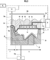
- FIG. 3 is an explanatory view showing an enlarged through hole of the present embodiment.
- FIG. 4 is an explanatory diagram showing a part of the manufacturing process of the second mold of the present embodiment.
- FIG. 5 is an explanatory diagram showing a part of the manufacturing process of the second mold of the present embodiment.
- FIG. 6 is an explanatory diagram showing a part of the manufacturing process of the second mold of the present embodiment.
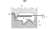
- FIG. 7 is an explanatory diagram schematically showing a shutter device as a comparative example.
- the laminated work forming apparatus 1 of the present embodiment includes a first mold 20 of a porous electroplated body and a second mold 30 of a porous electroplated body.
- the laminated work 40 such as an instrument panel molded by the laminated work forming apparatus 1 includes a work main body 42 and a sheet material 44 laminated on the work main body 42.
- the laminated work forming apparatus 1 includes a plurality of clamps 2 that grip the peripheral edge of the sheet material 44.
- the clamp 2 is movably supported by a support device (not shown) provided outside the peripheral edge of the first mold 20.
- FIG. 2 shows a state in which the work body 42 is placed on the first mold 20.
- the first mold 20 is provided with a plurality of suction holes 22 that open on the mounting surface on which the work main body 42 is mounted.
- the suction hole 22 may be formed of a pore or an open pore provided in the first mold 20 of the porous electroplated body.
- a pattern such as a grain or a satin finish is formed for transfer to the surface of the sheet material 44.
- the second mold 30 has a recess 36 so as to open at a position on the peripheral edge of the work body 42 when the second mold 30 is placed on the first mold 20 with the work body 42 and the sheet material 44 sandwiched between them.
- a box body 81 having a bottomed square tube shape is embedded so as to be embedded in the box.
- the first connection pipe 51a is connected to the bottom plate of the box body 81 (the plate located above in FIG. 3) by welding.
- the through hole 32 of the present embodiment is composed of pores or open pores provided in the lid 82 of the porous electroplated body provided so as to cover the opening on the cavity side of the box body 81 embedded in the recess 36. ..
- the through hole of the present invention is not limited to the pore or the open pore, for example, a plate is provided so as to cover the opening of the recess 36 formed on the inner surface of the second mold 30, and the hole is formed in the plate. It can also be configured with.
- the second mold 30 is provided with a plurality of ejection holes 34 penetrating so as to open at the position of the central portion of the work main body 42, which is a portion excluding the peripheral edge of the work main body 42.
- the ejection hole 34 may be composed of pores or open pores provided in the second mold 30 of the porous electroplated body.
- a first suction device 51 for sucking the sheet material 44 is connected to the through hole 32 of the lid portion 82 via the box body 81 via the first connection pipe 51a.
- a second suction device 52 for sucking the work body 42 is connected to the suction hole 22 via a second connection pipe 52a.
- a gas supply device 53 capable of supplying a gas such as air is connected to the ejection hole 34 via a third connection pipe 53a.
- a bypass path 53b is connected to the first connection pipe 51a and the third connection pipe 53a.
- a check valve 53c is interposed in the bypass path 53b.
- the check valve 53c is configured to allow the movement of gas from the first connection pipe 51a to the third connection pipe 53a and prevent the movement of gas from the third connection pipe 53a to the first connection pipe 51a. ing.
- the first mold 20 and the work main body 42 have a mold side protrusion 20a protruding from the first mold 20 toward the second mold 30 and the work main body 42.
- the work-side protrusions 42a projecting from the second mold 30 toward the second mold 30 are provided so as to surround the plurality of through holes 32 and extend along the outer edge of the adhesive region of the sheet material 44, respectively. There is.
- the gas supply device 53 passes through the ejection hole 34.
- the gas supplied to the surface of the sheet material 44 flows directly into the through hole 32 and is transmitted from the first suction device 51.
- the suction performance of the sheet material 44 by the first suction device 51 deteriorates.
- the second mold 30 may be provided with the mold side protrusion.
- the laminated work forming device 1 includes a control unit 61 that controls a first suction device 51, a second suction device 52, and a gas supply device 53.
- the control unit 61 is an electronic control unit composed of a CPU, a memory, and the like.
- the first suction device 51 by executing a control program held in the storage unit such as the memory by the CPU and transmitting an instruction signal,
- the second suction device 52 and the gas supply device 53 are controlled.
- the second mold 30 and the box body 81 are manufactured using a dedicated first electrocasting master mold 91.
- a plurality of nuts 83 are placed on the first electroforming master mold 91 so as to be positioned around the box body 81 and the box body 81.
- a pin for positioning the nut 83 is erected on the first electrocasting base 91.
- FIG. 4 shows only a part on which the box body 81 of the first electrocasting master mold 91 is placed.
- the box body 81 and the nut 83 are covered with the plating layer 81a by electric casting to complete the box body 81.
- the box body 81 of this embodiment includes a nut 83 and a plating layer 81a.
- the box body 81 is once removed from the first electrocasting master mold 91, a through hole is formed in the bottom plate of the box body 81, and the first connection pipe is formed.
- the 51a is connected to the box body 81 by welding.
- the box body 81 to which the first connection pipe 51a is connected is placed again on the first electrocasting base die 91, and the box body 81 is fitted into the recess 36 by electroforming.
- the second mold 30 is molded. The outer circumference of the second mold 30 is formed by electroforming and then trimmed by machining.
- the second mold 30 When the second mold 30 is molded by electroforming, if metal ions in the electrolytic solution are supplied to the inside of the first connecting pipe 51a, there is a risk that the electrocast body will be molded and clogged in the first connecting pipe 51a. is there. Therefore, the outer end of the first connection pipe 51a is capped so that the metal ions in the electrolytic solution are not supplied.
- the lid portion 82 that closes the opening of the box body 81 is fixed by screwing it to the nut 83 with the bolt 84.
- the first mold 20 and the second mold 30 are opened, and the work body 42 is placed on the first mold 20. Then, the sheet material 44 gripped by the clamp 2 is arranged between the work body 42 and the second mold 30. Then, the first mold 20 and the second mold 30 are brought into a closed state so as to approach each other.
- control unit 61 sucks the sheet material 44 by the first suction device 51 through the through hole 32 and the ejection hole 34 and attaches it to the inner surface of the second mold 30.
- the pattern formed on the inner surface of the second mold 30 can be transferred to the surface of the sheet material 44 (transfer step).
- the sheet material 44 is pressed against the work body 42 and adhered by the suction force of the second suction device 52 (adhesion step).
- the sheet material 44 is not adhered to the entire surface of the work body 42, but is adhered only to a portion exposed when assembled, such as an automobile, and a portion such as a peripheral edge hidden by other parts during assembly. In order to prevent improper assembly, the non-adhesive part is not adhered, and only the adhesive part is cut and the non-adhesive part is discarded.
- control unit 61 supplies gas between the sheet material 44 and the second mold 30 by the gas supply device 53 through the ejection hole 34, and the sheet material 44 is the second mold. Make it peel off from 30.
- control unit 61 sucks the sheet material 44 through the through hole 32 by the first suction device 51, and sucks the portion of the sheet material 44 that is not adhered to the work body 42 to the second mold 30.
- the suction force for sucking the sheet material 44 from the through hole 32 becomes stronger than the suction force for sucking the work body 42 from the suction hole 22.
- the suction force of the first suction device 51 and the second suction device 52 is set. By setting the suction force in this way, the sheet material 44 of the non-adhesive portion can be appropriately attracted to the second mold 30.
- FIG. 1 a comparative example is shown in FIG.
- the gas supply device 53 passes through the ejection hole 34.
- the gas supplied to the surface of the sheet material 44 flows directly into the through hole 32 and is transmitted from the first suction device 51.
- the suction performance of the sheet material 44 by the first suction device 51 deteriorates.
- the second mold 30 instead of the mold side protrusion 20a and the work side protrusion 42a, the second mold 30 may be provided with the mold side protrusion.
- the second mold 30 has a porous structure, if the box body 81 is not provided, even if the first suction device 51 tries to suck through the through hole 32, the second mold 30 having a porous structure has a porous structure. Gas may be sucked from an unintended place (that is, a place other than the through hole 32) through the through hole 32, and a desired suction force may not be obtained from the through hole 32.
- the peripheral surface of the recess 36 which is a connection portion connecting the through hole 32 and the first suction device 51, is made porous by plating treatment or coating with resin. It is conceivable to fill the holes based on the quality structure. However, the plating process and the application of the resin are troublesome, and the manufacturing cost of the laminated work forming apparatus increases.
- the box body 81 by fitting the box body 81 into the recess 36 of the second mold 30 and attaching the box body 81, even the second mold 30 having a porous structure penetrates without being plated or the like. It is possible to prevent the movement of gas between the inside and the outside of the box 81 in the portion other than the hole 32 and the connection port connected via the first connection pipe 51a of the first suction device 51, and the through hole. A desired suction force can be obtained from 32.
- bypass path 53b that bypasses the first connection pipe 51a and the third connection pipe 53a is provided, and the check valve 53c is interposed in the bypass path 53b.
- the present invention is not limited to this, and for example, a solenoid valve may be provided in the bypass path instead of the check valve 53c, and the solenoid valve may be controlled by the control unit.
Landscapes
- Engineering & Computer Science (AREA)
- Mechanical Engineering (AREA)
- Manufacturing & Machinery (AREA)
- Moulds For Moulding Plastics Or The Like (AREA)
Priority Applications (3)
| Application Number | Priority Date | Filing Date | Title |
|---|---|---|---|
| CN202080040381.XA CN113905870B (zh) | 2019-08-29 | 2020-03-30 | 层叠工件成型装置 |
| US17/637,501 US20220288839A1 (en) | 2019-08-29 | 2020-03-30 | Lamination workpiece molding device |
| JP2021541991A JPWO2021038944A1 (it) | 2019-08-29 | 2020-03-30 |
Applications Claiming Priority (2)
| Application Number | Priority Date | Filing Date | Title |
|---|---|---|---|
| JP2019-157275 | 2019-08-29 | ||
| JP2019157275 | 2019-08-29 |
Publications (1)
| Publication Number | Publication Date |
|---|---|
| WO2021038944A1 true WO2021038944A1 (ja) | 2021-03-04 |
Family
ID=74684399
Family Applications (1)
| Application Number | Title | Priority Date | Filing Date |
|---|---|---|---|
| PCT/JP2020/014573 WO2021038944A1 (ja) | 2019-08-29 | 2020-03-30 | 積層ワーク成形装置 |
Country Status (4)
| Country | Link |
|---|---|
| US (1) | US20220288839A1 (it) |
| JP (1) | JPWO2021038944A1 (it) |
| CN (1) | CN113905870B (it) |
| WO (1) | WO2021038944A1 (it) |
Families Citing this family (2)
| Publication number | Priority date | Publication date | Assignee | Title |
|---|---|---|---|---|
| WO2020152930A1 (ja) * | 2019-01-23 | 2020-07-30 | 本田技研工業株式会社 | 積層ワーク |
| EP3871856A1 (en) * | 2020-02-27 | 2021-09-01 | Essilor International | A thermoforming machine and method |
Citations (2)
| Publication number | Priority date | Publication date | Assignee | Title |
|---|---|---|---|---|
| JPS6049928A (ja) * | 1983-08-31 | 1985-03-19 | Hitachi Chem Co Ltd | 表皮つき成形品の製造法 |
| JPS61272126A (ja) * | 1985-05-27 | 1986-12-02 | Honda Motor Co Ltd | アンダ−カツトを備えたしぼ付合成樹脂成形体の成形方法および成形装置 |
Family Cites Families (15)
| Publication number | Priority date | Publication date | Assignee | Title |
|---|---|---|---|---|
| US1310440A (en) * | 1919-07-22 | Planograph co | ||
| US1263141A (en) * | 1916-07-15 | 1918-04-16 | Aranar Company | Process of making hollow rubber articles. |
| US2670501A (en) * | 1951-08-24 | 1954-03-02 | Us Rubber Co | Method of forming plastic material |
| US3219307A (en) * | 1961-09-20 | 1965-11-23 | Leeds Sweete Products Inc | Multi-part mold |
| US3124807A (en) * | 1962-01-19 | 1964-03-17 | Method of making three-dimensional | |
| US3247549A (en) * | 1965-04-27 | 1966-04-26 | Budd Co | Vacuum forming die construction |
| US3410936A (en) * | 1965-10-21 | 1968-11-12 | University Patents Inc | Vacuum casting method and apparatus for producing the metal fiber plastic articles |
| US3950919A (en) * | 1974-08-22 | 1976-04-20 | W. R. Grace & Co. | Apparatus and process for vacuum skin packaging |
| US4192701A (en) * | 1977-07-14 | 1980-03-11 | Brushaber Larry R | Double wall plastic article and method and apparatus for forming a double wall plastic article with a pair of thermoplastic sheets |
| CA2298032C (en) * | 1997-10-02 | 2000-09-05 | Angelo Rao | Method and apparatus for coating a decorative workpiece |
| US5993724A (en) * | 1997-12-31 | 1999-11-30 | Lyle H. Shuert | Method of forming non-skid plastic pallet |
| JP3984578B2 (ja) * | 2003-08-20 | 2007-10-03 | 日精樹脂工業株式会社 | ラミネート装置用ワークトレー |
| JP4765599B2 (ja) * | 2005-12-12 | 2011-09-07 | トヨタ車体株式会社 | 真空成形方法及びその装置 |
| KR101268789B1 (ko) * | 2010-12-29 | 2013-05-29 | (주)엘지하우시스 | 진공 금형 및 이를 이용한 진공 성형방법 |
| JP2019123607A (ja) * | 2018-01-18 | 2019-07-25 | グローリー株式会社 | ワーク積載装置およびワーク積載方法 |
-
2020
- 2020-03-30 CN CN202080040381.XA patent/CN113905870B/zh active Active
- 2020-03-30 WO PCT/JP2020/014573 patent/WO2021038944A1/ja active Application Filing
- 2020-03-30 JP JP2021541991A patent/JPWO2021038944A1/ja active Pending
- 2020-03-30 US US17/637,501 patent/US20220288839A1/en active Pending
Patent Citations (2)
| Publication number | Priority date | Publication date | Assignee | Title |
|---|---|---|---|---|
| JPS6049928A (ja) * | 1983-08-31 | 1985-03-19 | Hitachi Chem Co Ltd | 表皮つき成形品の製造法 |
| JPS61272126A (ja) * | 1985-05-27 | 1986-12-02 | Honda Motor Co Ltd | アンダ−カツトを備えたしぼ付合成樹脂成形体の成形方法および成形装置 |
Also Published As
| Publication number | Publication date |
|---|---|
| US20220288839A1 (en) | 2022-09-15 |
| CN113905870A (zh) | 2022-01-07 |
| CN113905870B (zh) | 2023-11-03 |
| JPWO2021038944A1 (it) | 2021-03-04 |
Similar Documents
| Publication | Publication Date | Title |
|---|---|---|
| WO2021038944A1 (ja) | 積層ワーク成形装置 | |
| US7097730B2 (en) | Method and apparatus for assembling a vehicle wheel | |
| KR101325548B1 (ko) | 오리피스 내장형 에이비에스용 솔레노이드밸브의 필터조립체 조립장치 및 이의 조립방법 | |
| EP2030475A2 (en) | Loudspeaker gasketing | |
| JP7047141B2 (ja) | 積層ワーク成形装置 | |
| US5839847A (en) | Molded article with captured fasteners | |
| JP7030215B2 (ja) | 積層ワーク成形方法及びその装置 | |
| KR102393495B1 (ko) | 수지 성형품의 제조 방법 및 수지 성형 장치 | |
| WO2021075106A1 (ja) | 積層ワーク成形方法、及びその装置 | |
| CN108297123A (zh) | 借助操纵器在部件上铺设组件的方法和装置 | |
| EP2567105A2 (en) | Pick and bond method and apparatus for transferring adhesive element to substrate | |
| JP3943181B2 (ja) | 複合装置の製造方法 | |
| JP7106684B2 (ja) | 積層ワーク | |
| JP4307236B2 (ja) | 積層パネルの成形装置及びその成形方法 | |
| US20220088893A1 (en) | Robotic terminal effector for automatic placement of inserts in a composite panel of the sandwhich type with a cellular core | |
| JP5795523B2 (ja) | 成形方法 | |
| JP3959683B2 (ja) | 表皮成形型 | |
| JPWO2019224977A1 (ja) | 樹脂−金属複合体を用いた部品の成形方法、および該部品成形用金型 | |
| JPH0711966Y2 (ja) | シートの接着装置 | |
| JPH07256769A (ja) | 繊維強化樹脂部材 | |
| JP4483712B2 (ja) | 接着構造体及び接着構造体の製造方法 | |
| CN115556384A (zh) | 碳纤维复合材料汽车前舱盖外板预浸料的铺叠-入模工艺 | |
| CN116141683A (zh) | 一种可键合的pdms封装方法 | |
| JP2009172786A (ja) | 真空成形装置 | |
| US20140027052A1 (en) | Method for coating an element with a coating layer |
Legal Events
| Date | Code | Title | Description |
|---|---|---|---|
| 121 | Ep: the epo has been informed by wipo that ep was designated in this application |
Ref document number: 20859331 Country of ref document: EP Kind code of ref document: A1 |
|
| ENP | Entry into the national phase |
Ref document number: 2021541991 Country of ref document: JP Kind code of ref document: A |
|
| NENP | Non-entry into the national phase |
Ref country code: DE |
|
| 122 | Ep: pct application non-entry in european phase |
Ref document number: 20859331 Country of ref document: EP Kind code of ref document: A1 |