WO2021038721A1 - 3次元造形装置用の造形材料のホットエンド、及びホットエンドを搭載した3次元造形装置 - Google Patents
3次元造形装置用の造形材料のホットエンド、及びホットエンドを搭載した3次元造形装置 Download PDFInfo
- Publication number
- WO2021038721A1 WO2021038721A1 PCT/JP2019/033541 JP2019033541W WO2021038721A1 WO 2021038721 A1 WO2021038721 A1 WO 2021038721A1 JP 2019033541 W JP2019033541 W JP 2019033541W WO 2021038721 A1 WO2021038721 A1 WO 2021038721A1
- Authority
- WO
- WIPO (PCT)
- Prior art keywords
- hot end
- backflow prevention
- passage
- prevention member
- filament
- Prior art date
- Legal status (The legal status is an assumption and is not a legal conclusion. Google has not performed a legal analysis and makes no representation as to the accuracy of the status listed.)
- Ceased
Links
Images


Classifications
-
- B—PERFORMING OPERATIONS; TRANSPORTING
- B29—WORKING OF PLASTICS; WORKING OF SUBSTANCES IN A PLASTIC STATE IN GENERAL
- B29C—SHAPING OR JOINING OF PLASTICS; SHAPING OF MATERIAL IN A PLASTIC STATE, NOT OTHERWISE PROVIDED FOR; AFTER-TREATMENT OF THE SHAPED PRODUCTS, e.g. REPAIRING
- B29C64/00—Additive manufacturing, i.e. manufacturing of three-dimensional [3D] objects by additive deposition, additive agglomeration or additive layering, e.g. by 3D printing, stereolithography or selective laser sintering
- B29C64/10—Processes of additive manufacturing
- B29C64/106—Processes of additive manufacturing using only liquids or viscous materials, e.g. depositing a continuous bead of viscous material
- B29C64/118—Processes of additive manufacturing using only liquids or viscous materials, e.g. depositing a continuous bead of viscous material using filamentary material being melted, e.g. fused deposition modelling [FDM]
-
- B—PERFORMING OPERATIONS; TRANSPORTING
- B22—CASTING; POWDER METALLURGY
- B22F—WORKING METALLIC POWDER; MANUFACTURE OF ARTICLES FROM METALLIC POWDER; MAKING METALLIC POWDER; APPARATUS OR DEVICES SPECIALLY ADAPTED FOR METALLIC POWDER
- B22F10/00—Additive manufacturing of workpieces or articles from metallic powder
- B22F10/20—Direct sintering or melting
- B22F10/22—Direct deposition of molten metal
-
- B—PERFORMING OPERATIONS; TRANSPORTING
- B22—CASTING; POWDER METALLURGY
- B22F—WORKING METALLIC POWDER; MANUFACTURE OF ARTICLES FROM METALLIC POWDER; MAKING METALLIC POWDER; APPARATUS OR DEVICES SPECIALLY ADAPTED FOR METALLIC POWDER
- B22F12/00—Apparatus or devices specially adapted for additive manufacturing; Auxiliary means for additive manufacturing; Combinations of additive manufacturing apparatus or devices with other processing apparatus or devices
- B22F12/50—Means for feeding of material, e.g. heads
- B22F12/53—Nozzles
-
- B—PERFORMING OPERATIONS; TRANSPORTING
- B29—WORKING OF PLASTICS; WORKING OF SUBSTANCES IN A PLASTIC STATE IN GENERAL
- B29C—SHAPING OR JOINING OF PLASTICS; SHAPING OF MATERIAL IN A PLASTIC STATE, NOT OTHERWISE PROVIDED FOR; AFTER-TREATMENT OF THE SHAPED PRODUCTS, e.g. REPAIRING
- B29C64/00—Additive manufacturing, i.e. manufacturing of three-dimensional [3D] objects by additive deposition, additive agglomeration or additive layering, e.g. by 3D printing, stereolithography or selective laser sintering
- B29C64/20—Apparatus for additive manufacturing; Details thereof or accessories therefor
- B29C64/205—Means for applying layers
- B29C64/209—Heads; Nozzles
-
- B—PERFORMING OPERATIONS; TRANSPORTING
- B33—ADDITIVE MANUFACTURING TECHNOLOGY
- B33Y—ADDITIVE MANUFACTURING, i.e. MANUFACTURING OF THREE-DIMENSIONAL [3D] OBJECTS BY ADDITIVE DEPOSITION, ADDITIVE AGGLOMERATION OR ADDITIVE LAYERING, e.g. BY 3D PRINTING, STEREOLITHOGRAPHY OR SELECTIVE LASER SINTERING
- B33Y30/00—Apparatus for additive manufacturing; Details thereof or accessories therefor
Definitions
- the present invention relates to a hot end of a modeling material for an FFF (FDM) type three-dimensional modeling device (three-dimensional printer), and a three-dimensional modeling device equipped with the hot end.
- FFF FFF
- three-dimensional printer three-dimensional modeling device equipped with the hot end.
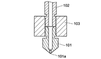
- a hot end for producing such a three-dimensional model for example, one having a structure as shown in FIG. 8 is known (see, for example, Non-Patent Document 1).
- This hot end has a structure in which the nozzle 101 is screwed into one end side of the heater block 103 so as to project the discharge portion 101a, and the barrel 102 having the supply portion of the modeling material is screwed into the other end side of the heater block 103. ing.
- the wire-shaped modeling material (filament) is inserted into the barrel 102 and fed, the modeling material is heated and melted by the heater block 103, flows to the discharge portion 101a, and is discharged from the discharge portion 101a. There is. At this time, a required amount of the filament is sent to the barrel 102 by a control signal, so that the required amount is discharged from the discharge portion 101a, and the position of the discharge portion 101a is a modeling table that forms a modeled object. By moving relative to (not shown) in the xyz direction, the discharged modeling materials are laminated to form a desired three-dimensional modeled object.
- a heat radiation fin (not shown) may be provided on the upper part of the barrel 102 so that the filament does not melt in the barrel 102, or the barrel 102 may be forcibly cooled by a fan or water cooling. It is done.
- the inventor of the present invention causes this problem by cooling the filament with a heat radiation fin or the like in order to prevent the filament on the barrel 102 side from melting during continuous molding, so that the filament is formed in the filament passage (flow path) of the barrel 102.
- the diameter of the discharge port for discharging the melted filament is smaller than the diameter of the filament to be fed, so that the filament melted on the nozzle 101 side when the filament is pressed and fed is , Invasion (backflow) into the barrel 102 side through the gap (clearance) between the inner wall of the passage and the filament due to the difference between the inner diameter of the passage and the wire diameter of the filament, that is, the gap between the filament in the solid state and the inner wall of the passage.
- the filament melted on the nozzle 101 side invades the barrel 102 side through the clearance and sticks in the passage on the barrel 102 side, causing clogging of the filament in the passage in the barrel 102 and feeding the filament.
- the molding Since it hinders the discharge of the molding material, the molding is hindered. Therefore, even if an attempt is made to prevent the backflow of the melted filament by making the inner diameter of the passage close to the wire diameter of the filament and making the clearance as small as possible, the wire diameter of the filament is originally not constant and includes a tolerance. Therefore, it does not effectively prevent backflow.
- the present invention has been made in view of such a situation, and it is possible to prevent the filament from being clogged in the passage by preventing the molten molding material from flowing back to the filament supply side more than necessary. It is an object of the present invention to provide a highly reliable hot end capable of good continuous modeling and a ternary modeling apparatus equipped with a hot end.
- the present inventor has provided a backflow prevention member for preventing backflow of the melted modeling material at the hot end for a three-dimensional modeling device, and a melting portion where the filament is melted. It has been found that the backflow of the modeling material is suppressed and the hot-end passage is less likely to be clogged by providing the space between the filament and the supply port to which the filament is supplied.
- the present invention includes a supply port for supplying a filamentous modeling material, a discharge port for discharging the melted modeling material, and a discharge head having a passage for linearly communicating the supply port and the discharge port.
- a hot end for a three-dimensional modeling apparatus including a heating means for melting the modeling material in the passage, and the heating means in the passage between the heating means and the supply port.
- the hot end is provided with a ring-shaped backflow prevention member, which prevents the molding material melted by the above-mentioned flow from flowing back through the passage on the supply port side, and is inserted in contact with the molding material.
- the ring-shaped backflow prevention member for inserting the filament-shaped modeling material (filament) in contact with the passage since the ring-shaped backflow prevention member for inserting the filament-shaped modeling material (filament) in contact with the passage is arranged, the filament and the inner wall of the ring of the backflow prevention member are arranged. Since the filament can be pushed (supplied) by making the gap between them substantially negligible, the molding material melted by the heat of the heating means passes through the backflow prevention portion to the supply port side (upstream side). Backflow inside is prevented. In this way, it is possible to effectively prevent the molten modeling material from entering (backflow) into the passage on the upstream side of the backflow prevention member, so that the passage for supplying the modeling material is clogged.
- a highly reliable hot end that can be prevented and can be continuously molded well.
- the discharge head is integrally formed, for example, a dichotomized portion of a melting portion provided with a heating means for melting the filament and a supply portion for supplying the filament to the melting portion, and further. May consist of a trisection.
- a metal member attached so as to surround the area where the backflow prevention member is arranged in the passage may be provided. Further, a case member fixed to the metal member and covering the heating means may be provided.
- the temperature distribution in the passage is made appropriate, and the filament can be prevented from melting on the upstream side of the passage. That is, the metal member can increase the heat capacity and surface area of the region around the backflow prevention member, and can prevent the heat from the heating means from being transferred to the upstream side of the backflow prevention member. That is, the metal member functions as a cooling member. Therefore, the boundary between the solid portion of the filament and the melted and fluidized portion can be made clearer, and the filament can be prevented from softening in the passage on the upstream side of the backflow prevention member. Clogged filaments in the passage can be effectively prevented.
- the heat generated by the heating means can be appropriately dissipated from the outer surface of the case member, and the heat can be prevented from being transferred to the upstream side of the passage, and the heat can be transferred to the inside of the case member. It can be confined and the heat from the heating means can be more effectively used to melt the filament.
- the temperature distribution in the passage appropriate, it is possible to prevent the filament from melting on the upstream side of the passage, and it is possible to further prevent the filament from being clogged in the passage.
- the backflow prevention member is arranged in contact with the step portion in the passage.
- the backflow prevention member By arranging the backflow prevention member in contact with the step portion, it is possible to prevent the backflow prevention member from being pushed into the downstream side of the passage, and the backflow prevention member can be held at an appropriate position.
- the discharge head has a tubular shape, and the thickness of the peripheral wall of the region where the backflow prevention member of the passage is arranged can be made thinner than the thickness of the peripheral wall of the region where the heating means is arranged. .. By reducing the thickness of the peripheral wall in the region where the backflow prevention member of the discharge head is arranged, it is possible to suppress the heat generated by the heating means from being transmitted through the peripheral wall to the upstream side of the backflow prevention member.
- annular retaining member having an inner diameter larger than that of the backflow prevention member for preventing the backflow prevention member from moving to the supply port side is provided. Can be placed. This makes it possible to hold the backflow prevention member at a desired position in the flow path.
- the backflow prevention member may be made of a heat-resistant elastic body, a superelastic alloy, or a superelastic plastic type alloy. As a result, even if there is a tolerance in the filament diameter, the inner diameter of the ring of the backflow prevention member can be changed so as to follow the change in the wire diameter of the filament, and the ring can be brought into close contact with the filament with substantially no gap. The filament can be fed and backflow can be prevented.
- the ring shape may be a spiral shape, a coil shape, or a coil spring shape.
- a C-plane or an R-plane may be formed on the inner circumference of the backflow prevention member.
- the backflow prevention member may be spiral, coiled or coil spring-shaped, or the inner circumference of the backflow prevention member may be C.
- the frictional resistance can be adjusted so that filament feeding (supply of filament to the melting portion) can be suitably performed, and a gap between the backflow prevention member and the filament can be achieved. Can be more effectively prevented from occurring.
- the three-dimensional modeling apparatus of the present invention is characterized by being equipped with the hot end for the above-mentioned three-dimensional modeling apparatus.
- the present invention it is possible to prevent the molding material (filament) melted on the downstream side of the passage from flowing back to the upstream side of the backflow prevention member arranged in the passage, so that the molding operation is hindered. It is possible to use a hot end while preventing the occurrence of clogging, and it is possible to provide a highly reliable hot end capable of realizing good and continuous modeling operation, and a three-dimensional modeling device equipped with the hot end. ..
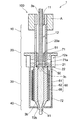
- FIG. 1 is a cross-sectional explanatory view of the hot end 1 of the present invention.
- the hot end 1 has a supply unit 10 provided with a supply port 11 to which a filament-shaped modeling material (filament 3a) is supplied, a melting unit 30 for melting the supplied modeling material, and a discharge port 41 for discharging the melted modeling material.
- a discharge head 100 having a discharge unit 40 including, a heat insulating unit 20 forming between the supply unit 10 and the melting unit 30, and a passage 12 for a modeling material communicating from the supply port 11 to the discharge port 41. It is formed.
- a mounting jig A for mounting the hot end 1 on the three-dimensional modeling device is mounted on the supply unit 10.
- the hot end 1 includes a heating means (heating head) 60 attached to the melting portion 30, and the heat applied from the heating means 60 to the melting portion 30 of the discharge head 100 melts the modeling material in the passage 12. Will be done.
- a heating means heating head
- two heating means 60 are provided so as to sandwich the discharge head 100.
- a ring-shaped backflow prevention member 50 that prevents the modeling material melted by the heating means 60 from flowing back toward the supply port 11 is arranged. There is.
- the backflow prevention member 50 is provided at the inlet (the boundary between the heat insulating portion 20 and the melting portion 30) where the modeling material of the melting portion 30 is supplied inside the passage 12 of the discharge head 100. It is provided in contact with the upper surface of the step portion 21. It is fixed so as to be sandwiched between an annular fixing member (retaining member) 51 having an inner diameter larger than that of the backflow prevention member 50 and a step portion 21.
- the diameter of the passage 12 is formed so as to be smaller on the melting portion 30 side than on the heat insulating portion 20 side at the entrance of the melting portion 30.
- the backflow prevention member 50 is arranged so as to come into contact with the step portion (step portion 21) where the diameter of the passage 12 changes so as not to enter the passage 12 of the melting portion 30.
- the filament 3a is inserted into the passage 12 from the supply port 11 in a solid state, is sent to the melting portion 30 through the ring-shaped backflow prevention member 50 installed in the passage 12, and is fed by the heat given from the heating means 60. It is melted and discharged from a discharge port 41 provided in the discharge unit 40.
- the filament in the solid state is shown as 3a
- the filament in the melted state is shown as 3b
- the filament in the mixed state of solid and liquid is shown as 3c.
- the tip end portion (lower end portion) of the retaining member 51 on the melting portion 30 side is in contact with the backflow prevention member 50.
- the backflow prevention member 50 is fixed so as to be sandwiched between the retaining member 51 and the step portion 21 of the passage 12, but the backflow prevention member 50 is press-fitted into the passage 12 without the retaining member 51 being provided.
- the supply portion 10 and the heat insulating portion 20 on the upstream side of the discharge head 100 may be barrel-shaped, and the melting portion 30 and the discharge portion 40 on the downstream side may be nozzle-like.
- the backflow prevention member 50 may be arranged in the passage 12 so as to sandwich the backflow prevention member 50 between them.
- the backflow prevention member 50 is formed in a ring shape that can surround, contact, and hold a part of the peripheral edge in the length direction of the filament.
- the backflow prevention member 50 is preferably formed of a material having elasticity whose inner diameter can follow fluctuations within the tolerance of the wire diameter of the filament and maintain a state of being closely held. In this case, for example, the diameter. If a filament of 1.75 mm and a wire diameter tolerance of ⁇ 0.05 mm is used, the inner diameter of the backflow prevention member 50 is formed to be 1.70 mm and is in the range of 1.70 mm to 1.80 mm. It is formed so as to be able to follow the fluctuation of the diameter.
- the hot end 1 shown in FIG. 1 includes a metal member (metal block) 71 and a case member (cover member) 72 attached to the outer periphery of the discharge head 100.
- the metal member 71 is a substantially cylindrical member having a brim-shaped extending portion at the upper portion, and a through hole matching the outer shape of the discharge head 100 is provided in the center thereof.
- the discharge head 100 is inserted through the through hole, and the metal member 71 is attached in contact with the outer periphery of the region where the backflow prevention member 50 of the discharge head 100 is arranged.
- a mounting hole 71a is formed on the side surface of the metal member 71.
- the metal member 71 is fixed to the discharge head 100 by a fixing means such as a set screw inserted into the mounting hole 71a. Further, when fixing the metal member 71, the lower side is slightly stretched on a part of the outer periphery (position facing the step portion 21 in the passage 12) of the boundary with the heat insulating portion 20 above the melting portion 30 of the discharge head 100. A step portion 22 is provided, and the metal member 71 is fitted from the supply port 11 side at the upper end of the discharge head 100, and is positioned so that the lower end portion thereof abuts on the upper surface of the step portion 22. The mounting position of the metal member 71 with respect to the discharge head 100 is movable along the length direction of the discharge head 100.
- the heat capacity near the boundary between the melting portion 30 and the heat insulating portion 20 of the discharge head 100 increases, and the temperature in the region increases. Is hard to rise. Further, the heat dissipation effect can be obtained by increasing the surface area of the metal member 71, particularly the brim-shaped portion. Therefore, it is possible to suppress the heat on the downstream side applied from the heating means 60 to the melting portion 30 of the discharge head 100 to melt the filament to the heat insulating portion 20 on the upstream side, and it is appropriate from the heat insulating portion 20 to the supply portion 10. The temperature can be adjusted.
- the boundary between the solid portion of the filament and the melted portion shifts to the region where the backflow prevention member 50 is arranged, and the filament in the portion held by the backflow prevention member 50 melts to prevent backflow.
- the possibility that the function of preventing the backflow of the filament by the member 50 is impaired is suppressed. In other words, the solid state of the filament through which the backflow prevention member 50 is inserted can be more reliably maintained.
- the case member 72 has a substantially cylindrical shape, and the upper portion thereof is attached and fixed so as to fit the outer circumference of the metal member 71.
- a notch (groove) 72a is formed in the upper part of the case member 72, and the mounting holes 71a formed on the side surface of the metal member 71 described above are aligned with the groove 72a to fix a push screw or the like.
- the case member 72 covers the entire periphery of the melting portion 30 to which the heating means 60 of the discharge head 100 is attached.
- a hole 72b for projecting the discharge port 41 is provided on the side opposite to the side fitted with the metal member 71 (the discharge portion 40 side).
- the case member 72 has a function of reusing the heat transferred from the discharge head 100 to the metal member 71 by refluxing it to the melting portion 30 side. Since the cover member 72 is provided in addition to the metal member 71, the temperature distribution (temperature gradient) in a region having a predetermined width from the vicinity of the inlet of the melting portion 30 to the discharging portion 40 is passed through depending on the type of filament. It is possible to obtain a stable temperature distribution in which 12 clogging is unlikely to occur.
- the heat dissipation effect of the surface of the case member 72 can be expected, and the heat on the downstream side applied from the heating means 60 to the melting portion 30 of the discharge head 100 to melt the filament is transferred to the heat insulating portion 20 on the upstream side. It can be further suppressed, and a more appropriate temperature can be obtained from the heat insulating portion 20 to the supply portion 10.
- the space between the case member 72 and the discharge head 100 covered by the case member 72 may be filled with a heat-resistant insulating material such as glass fiber. Since the groove portion 72a formed in the upper portion of the case member 72 has a predetermined length in the vertical direction, the mounting position of the case member 72 with respect to the metal member 71 can be moved in the vertical direction. .. That is, the range covered by the case member 72 can be arbitrarily adjusted depending on the mounting positions of the metal member 71 and the case member 72 with respect to the discharge head 100.
- FIG. 2 (A) A front view of the discharge head 100 used for the hot end 1 shown in FIG. 1 as seen from the side on which the heating means 60 is attached is shown in FIG. 2 (A), and a bottom view as seen from the discharge port 41 side. Is shown in FIG. 2 (B).
- the supply unit 10, the heat insulating unit 20, the melting unit 30, and the discharge unit 40 are integrally formed of, for example, stainless steel, nickel alloy, titanium, titanium alloy, or ceramics. It may be there.
- the discharge head 100 may be formed by combining independent members, and other members may intervene in any or all of the members.
- the thermal conductivity of the material of the member used for the melting portion 30 and the discharge portion 40 is higher than the thermal conductivity of the material of the member used for the heat insulating portion 20.
- a high value is preferable from the viewpoint of effectively utilizing the heat of the heating means 60 for melting the modeling material while suppressing heat transfer to the supply unit 10.
- the discharge head 100 shown in FIG. 2 is formed by cutting, for example, a columnar metal rod.
- the total length of the portion of the discharge head 100 shown in FIG. 2 (A) is, for example, 33 mm.
- the discharge head 100 is formed by using, for example, 64 titanium (an alloy of titanium mixed with 6% by mass of aluminum and 4% by mass of vanadium).
- the supply unit 10 and the heat insulating unit 20 have a cylindrical shape (cylindrical shape) having a diameter of, for example, 3 mm, and a length thereof, for example, 17.5 mm.
- a passage 12 having a diameter of, for example, 2.3 mm is formed in the central portion of the supply portion 10 and the heat insulating portion 20.
- the heat insulating portion 20 is formed so that the thermal resistance is larger than that of the melting portion 30.
- openings 20a having a length of 6 mm and a width of 1.8 mm are formed in pairs facing the passage 12 so that the cross-sectional area of the heat insulating portion 20 can be reduced to increase its thermal resistance.
- One or a plurality of openings 20a may be provided in the length direction and / or the width direction of the discharge head 100, and the size thereof can be appropriately determined.
- the melting portion 30 is formed in a square columnar shape having a rectangular cross-sectional shape having a side of 3.2 mm, for example, the corner portion formed on the C surface, and the length thereof is, for example, 12.5 mm.
- a heating means 60 may be attached to each of the four side surfaces (planar portions) of the square columnar melting portion 30.
- the melting portion 30 may be formed in a prismatic shape (for example, a triangular pillar or a pentagonal pillar) other than the square pillar.
- a passage 12 having a diameter of, for example, 1.8 mm is formed so as to communicate with the passage 12 of the heat insulating portion 20.
- the diameter of the passage 12 in the melting portion 30 is formed to be smaller than the diameter of the passage 12 in the heat insulating portion 20, and backflow is prevented at the boundary between the melting portion 30 and the heat insulating portion 20 where the passage diameter changes.
- a step portion 21 capable of fixing the member 50 is formed. That is, the thickness of the peripheral wall of the passage 12 in the heat insulating portion 20 is thinner than the thickness of the peripheral wall of the passage 12 in the melting portion 30.
- openings may be formed on the four side surfaces of the melting portion 30 to expose the passage 12 in order to heat and melt the modeling material inside thereof more efficiently.
- the discharge portion 40 has, for example, a substantially conical shape with a length of 3 mm, and has a shape that tapers from the melting portion 30 toward the tip end portion (discharge port 41) side of the discharge portion 40.
- the discharge portion 40 is formed to have a diameter of, for example, 3 mm at the boundary with the melting portion 30, and the tip portion where the discharge port 41 is formed is formed to have a diameter of, for example, 1.5 mm, and the discharge port 41 has a diameter of, for example, 0.4 mm. It is formed.
- the mounting jig A is fitted and connected to the supply unit 10.
- the mounting jig A has, for example, a cylindrical shape (cylindrical shape) having a length of 5 mm and a diameter of 4 mm.
- the mounting jig A has a role as a mounting portion for mounting the hot end 1 on the main body of the three-dimensional modeling apparatus.
- the size of each part of the discharge head 100 and the passage 12 described above can be appropriately changed according to the size of the filament and the like.
- the backflow prevention member 50 in the hot end 1 of the present invention is provided to prevent the melted modeling material from flowing back toward the supply unit 10.
- a filament is inserted through the ring-shaped backflow prevention member 50, and the backflow prevention member 50 is substantially in close contact with the outer periphery of a part of the filament without any gap.
- the filament is held by the backflow prevention member 50 with a force that does not hinder the feeding of the filament during the molding operation.
- the filament used for three-dimensional modeling can vary in diameter in its length direction. Since a filament having a diameter of 1.75 mm can have a tolerance of, for example, ⁇ 0.05 mm, the backflow prevention member 50 is made of a material having elasticity that can follow the fluctuation of the diameter and adhere to the filament.
- the material used for the backflow prevention member 50 preferably has heat resistance to the temperature at which the filament melts, and a Ni—Ti alloy, which is a superelastic alloy, can be used as an example.
- the Ni—Ti alloy, which is a superelastic alloy has a recovery strain of about 8% due to its superelasticity, and can sufficiently follow fluctuations in filament diameter.
- a resin having heat-resistant elasticity may be used, and for example, a perfluoroelastomer (FFKM) that can maintain the physical characteristics of rubber even at a high temperature of about 300 ° C. can be used.
- FFKM perfluoroelastomer
- a superplastic alloy having both superelastic properties and superplastic properties can also be used.
- the superplastic alloy is preferable because it is extremely easy to mold due to its superplastic property that it can be cold-worked at 99.9% or more at room temperature and has excellent workability.
- An example of a super-elasto-plastic alloy is "Rubber Metal” (registered trademark) manufactured by Toyotsu Material Incorporated, which belongs to a ⁇ -type titanium alloy.
- the shape of the backflow prevention member 50 is formed in a ring shape so that the inside thereof can be adhered to and held by the filament in a solid state.
- the ring shape means, for example, a spiral shape, a coil shape, a coil spring shape, a tubular shape, a tubular shape, a washer shape (flat washer shape, a countersunk washer shape, a round washer shape), which can surround and hold the outer circumference of the filament. It has a broad meaning including an O-ring shape and a tapered tubular shape.
- the number of turns of the coil is preferably, for example, 2 to 3 turns.
- a C-plane or an R-plane may be formed on the inner circumference of the backflow prevention member 50, the contact area between the filament and the backflow prevention member 50 can be adjusted, and the force for holding the filament can be appropriately adjusted.
- the backflow prevention member 50 may be a ring-shaped member having both ends connected or not connected, or a continuous O-ring-shaped member, and has a structure including a super-elasto-plastic body or a rubber-like material having a large expansion and contraction. It may be. In particular, a spiral, coiled or coil spring-shaped wire rod made of an elastic material having a circular cross section or an elliptical cross section is more preferable.
- one backflow prevention member 50 is provided in the passage 12, but a plurality of backflow prevention members 50 may be provided. That is, a plurality of ring-shaped members can be stacked and arranged in the passage 12.
- the ring-shaped backflow prevention members 50 may be arranged near the inlet of the melting portion 30 in the passage 12 so as to be in close contact with each other and stacked. As a result, the filament is more reliably held by the backflow prevention member 50.
- the plurality of ring-shaped backflow prevention members 50 may be arranged apart from each other.
- an annular retaining member 51 is provided on the supply port 11 side of the backflow prevention member 50, and the backflow prevention member 50 is sandwiched between the retaining member 51 and the step portion of the passage 12. And fixed.
- a metal such as stainless steel, nickel alloy, titanium, or titanium alloy is preferably used from the viewpoint of stably fixing the backflow prevention member 50 in the passage 12, and is a shape memory alloy.
- Ni—Ti alloys are more preferably used.
- Engineering plastics such as polytetrafluoroethylene (PTFE) or polyetheretherketone (PEEK) may be used.
- the backflow prevention member 50 may be fixed by joining into the passage 12 using a heat-resistant adhesive such as a metal paste or an inorganic adhesive.
- the backflow prevention member 50 needs to have a solid filament at a holding portion from the viewpoint of preventing backflow of the melted filament. That is, in the portion where the backflow prevention member 50 is provided (near the boundary between the melting portion 30 and the heat insulating portion 20), the temperature needs to be controlled to a temperature at which the filament does not melt. In order to suppress the temperature rise in the region where the backflow prevention member 50 is provided due to the heat transferred from the heating means 60 to the upstream side of the filament of the melting portion 30, for example, the metal member 71 made of aluminum or stainless steel is formed in the melting portion. It may be provided on the outer periphery near the boundary between the 30 and the heat insulating portion 20.
- FIG. 3 (A) A front view of an example of the metal member 71 is shown in FIG. 3 (A), and a bottom view is shown in FIG. 3 (B).
- the metal member 71 can be formed by using a known metal such as aluminum or stainless steel. From the viewpoint of increasing the heat capacity of the portion to which the metal member 71 of the discharge head 100 is attached, it is preferable to use a material having a large specific heat for the metal member 71. Further, from the viewpoint of heat dissipation, it is preferable that the metal member 71 is subjected to a treatment for improving heat dissipation. For example, aluminum having an alumite treatment on its surface is preferably used.
- the metal member 71 is a member having a cylindrical shape having a cavity having a substantially same diameter at the center thereof, and has a collar-shaped portion having a large outer diameter formed on one end side thereof.
- the outer diameter of the collar-shaped portion is formed to be, for example, 14 mm in diameter.
- the outer diameter of the portion having a cylindrical shape other than the brim-shaped portion is formed to be, for example, a diameter of 7.9 mm.
- the cavity of the metal member 71 is formed to match the shape and size of the heat insulating portion 20 of the discharge head 100, and is formed to have a diameter of, for example, 3.1 mm.
- the heat capacity of the region near the boundary between the melting portion 30 and the heat insulating portion 20 increases. Assuming that the heat capacity in this region increases, a large amount of heat is concentrated on the modeling material remaining in the passage 12 near the boundary between the melting portion 30 and the heat insulating portion 20 when the discharge of the modeling material is stopped. However, the temperature does not rise easily. Therefore, it is possible to prevent the boundary between the solid portion of the modeling material and the melted and fluidized portion from shifting to the heat insulating portion 20 side. That is, melting of the filament in the portion held by the backflow prevention member 50 can be suppressed, and clogging of the modeling material in the passage 12 can be suppressed.
- the metal member 71 also has an effect of radiating heat at the boundary between the melting portion 30 and the heat insulating portion 20 or in the vicinity of the boundary portion, and the effect of preventing clogging can be further enhanced by enhancing the heat radiating effect depending on the shape.
- the metal member 71 On the side surface of the metal member 71, four through holes (mounting holes) 71a through which the fixing means to the discharge head 100 can be inserted are formed.
- the metal member 71 can be attached to an arbitrary position in the length direction of the heat insulating portion 20 of the discharge head 100. That is, the position is adjusted and attached so that the temperature of the region near the boundary between the melting portion 30 and the heat insulating portion 20 is appropriately maintained according to the melting temperature of the filament used, the feeding speed of the filament, and the like. Can be.
- the cavity of the metal member 71 is adapted to the shape of the outer circumference of the heat insulating portion 20 of the discharge head 100 and is attached to the heat insulating portion 20, but the cavity of the metal member 71 is shown. It is also possible to adapt it to the shape of the outer circumference of the melting portion 30 and attach it to the outer circumference of the melting portion 30.
- FIG. 4 (A) A front view of an example of the case member 72 is shown in FIG. 4 (A), and a bottom view is shown in FIG. 4 (B).
- the case member 72 is formed by using a known metal such as aluminum or stainless steel. When aluminum is used, it is preferable that the surface is anodized.
- the case member 72 is a member having a substantially cylindrical shape, and one end side thereof is fitted with the metal member 72. On the side opposite to the portion fitted with the metal member 72, there is a bottom surface in which a hole 72b for discharging the discharge port 41 of the discharge head 100 is formed in the central portion.
- the diameter of the cavity of the case member 71 into which the metal member 71 is fitted is formed to be, for example, a diameter of 8 mm.
- the length of the case member 71 is, for example, 18.0 mm.
- the case member 72 is provided to effectively utilize the heat transferred from the discharge head 100 to the metal member 71 for heating on the melting portion 30 side.
- a stable temperature distribution (temperature gradient) in this region can be formed. That is, the case member 72 brings about an energy saving effect that effectively utilizes the heat given to the discharge head 100 from the heating means 60, and stabilizes the temperature distribution in a predetermined region from the melting portion 30 to the discharge portion 40, and is stable. It can contribute to various modeling operations.
- a groove 72a is formed on the side of the case member 72 connected to the metal member 71.
- the metal member 71 and the case member 72 are attached to the discharge head 100, they are arranged so that the positions of the attachment holes 71a of the metal member 71 and the grooves 72a of the case member 72 coincide with each other, and the grooves 72a and the case member 72 are attached.
- the metal member 71 and the case member 72 are fixed to the discharge head 100 by a fixing means such as a set screw inserted through the hole 71a.
- the attachment position with respect to the metal member 71 is movable in the length direction of the case member 72. That is, the region covered by the case member 72 has a structure that can be changed according to the mounting position of the metal member 71 with respect to the discharge head 100 and the mounting position of the case member 72 with respect to the metal member 71.
- the temperature distribution (temperature gradient) in a region having a predetermined width from the discharge portion 40 to the heat insulating portion 20 can be adjusted. It is possible to approach an appropriate temperature gradient according to the type and characteristics (physical properties) of the modeling material, suppress the clogging of the modeling material in the passage on the supply section 10 side of the hot end 1, and appropriately melt. The modeling material in the state can be satisfactorily discharged from the discharge port 41.
- the heating means 60 in the hot end 1 for example, a heating head having a thick film resistor layer formed on an insulating substrate, a heat block, or the like can be widely used, but heating is performed in terms of responsiveness and size. It is preferable to use a head.
- An example of the structure of the heating means (heating head) 60 is shown in FIG.
- the heating head 60 attached to the melting portion 30 of the discharge head 100 includes, for example, a rectangular plate-shaped ceramic substrate (insulating substrate) 61 having a thickness of 0.3 mm, a length of 12 mm, and a width of 5 mm, such as alumina or zirconia, and an insulating substrate 61.
- It has a band-shaped heat generating resistor 62 formed on the surface of the insulating substrate 61, and an electrode 63 formed on the surface of the insulating substrate 61 so as to connect to both ends of the heat generating resistor 62.
- the surface of the heat generating resistor 62 may be coated with a protective layer (dielectric layer) such as glass containing a filler, or the surface of the heat generating resistor 62 may be covered with another insulating substrate.
- the heating means 60 is a heat generating resistor by printing, for example, an alloy powder such as Ag, Pd, Pt, or a thick film paste containing ruthenium oxide on an insulating substrate 61 on a predetermined pattern, drying, and firing at a predetermined temperature. 62, the electrode 63 can be formed.
- a notch is formed in the forming portion of the electrode 63 of the insulating substrate 61 in order to improve the connection strength between the electrode 63 and the lead (not shown).
- two notches are provided for each electrode 63, but the number of notches may be one or three or more.
- one or a plurality of through holes may be provided instead of the cutout portion, or the cutout portion and the through hole may be used in combination. That is, the notch and the through hole are provided at a high temperature by increasing the connection area or taking measures such as an anchor effect to obtain mechanical engagement in order to improve the connection strength between the electrode 63 and the lead. Even when it is heated or moved two-dimensionally or three-dimensionally, connection failure does not occur.
- the heating means 60 when the heating means 60 is attached to the discharge head 100, the heating means 60 discharges the back surface (the surface of the insulating substrate 61 where the heat generating resistor 62 is not formed).
- a silver-based thick film paste (Ag containing, for example, glass or Cu) is applied as a bonding material to the flat surface portion (side surface of a square pillar) of the melting portion 30 of the head 100, fired, and bonded.
- another insulating substrate 66 is provided on the opposite side of the heat generating resistor 62 from the insulating substrate 61.
- the heating means 60 are attached to the melting portion 30 of the discharge head 100 so as to face each other, but the heating means 60 is attached to each of the four flat portions of the square columnar melting portion 30.
- the heating means 60 may be provided on all four flat surfaces, and the hot end 1 may be provided with the four heating means 60, or the heating means 60 may be provided only on the two adjacent flat surfaces. ..
- heating means 60 When the heating means 60 is small, it is possible to provide a plurality of heating means 60 in the length direction in one flat surface portion. Since the melting portion 30 is formed in a square columnar shape and has four flat portions, the degree of freedom of the mounting position of the heating means 60 is remarkably improved, and the temperature distribution in the passage 12 in the melting portion 30 is used. It is possible to make more appropriate adjustments according to the type (physical properties) of the filament. For example, heating means 60 are arranged on two opposing flat surfaces on the upstream side of the filament of the melting portion 30, and heating means 60 are arranged on all four flat surfaces on the downstream side of the filament, and on the downstream side. The arrangement of the heating means 60 can also be configured so that the temperature distribution is higher.
- the temperature of the substrate is also measured by the heat generating resistor 62 of the heating means 60 at the hot end 1, and the temperature of the melting portion 30 is controlled by adjusting the heating amount by the heating resistor 62 according to the measured temperature.
- this drive circuit is an example of driving with a DC or AC power supply 64
- the power supply 64 is an adjusting unit that adjusts the voltage and application time of a battery, a commercial power supply, or a commercial power supply by a transformer or the like to adjust the applied power. It is connected to the heat generating resistor 62 via.
- the voltage supplied by the commercial AC power supply 64 is adjusted by the power adjusting unit and adjusted to a desired temperature. As a result, no DC power supply is required, and no power supply cooling fan is required. However, a battery-powered DC power source may be used. Further, although not shown, heating may be performed by pulse driving to which a pulse is applied. In that case, in addition to changing the voltage, the duty cycle can be changed, and the execution applied power related to heat generation can be adjusted by phase control or the like.
- the temperature can be detected by using the heat generating resistor 62 and changing its resistance value. As shown in FIG. 6, the change in the resistance value of the heat-generating resistor 62 can be detected by measuring the voltage across the shunt resistor 65 connected in series with the heat-generating resistor 62. When the voltage applied to the heat generating resistor 62 is constant, if the change in the current is known, the change in the resistance value can be known. That is, the resistance value of the heat generating resistor 62 has a temperature characteristic that changes depending on the temperature. Therefore, by detecting the temperature characteristic (temperature coefficient) in advance, if the resistance value is known, the temperature of the heat generating resistor 62, that is, the insulating substrate 61 can be known.
- the temperature characteristic temperature coefficient
- This temperature detection is performed by a control means.
- the shunt resistor 65 should have a resistance value as low as possible in order to avoid the influence of heat generation. Further, a resistor having a temperature coefficient as small as possible is preferable, and the current is set to be small in order to avoid heat generation due to the current.
- a control signal is output from the control means so that the voltage applied to the heat generating resistor 62 is adjusted by the adjusting unit according to the temperature measured by this temperature measurement, and the temperature of the heating resistor 62, that is, the insulating substrate 61. Is adjusted to the desired temperature.
- the temperature of the heat generating resistor 62 is controlled so that the temperature distribution in the passage 12 is stable.
- a temperature monitoring means such as a thermistor or a thermocouple.
- the temperature of the portion where the backflow prevention member 50 is provided may be measured by the sensor).
- a temperature sensor for measuring the temperature of the melting portion 30 may be attached to the flat surface portion of the melting portion 30. Since the melting portion 30 is formed in a square columnar shape, the degree of freedom in the mounting position of the temperature sensor is high, and the temperature of the melting portion 30 can be monitored more accurately.
- the voltage applied to the heat generating resistor 62 of the heating means 60 is controlled by the control signal based on the temperature measured by the temperature sensor, and the temperature of the portion where the backflow prevention member 50 is provided can be controlled.
- the melting portion 30 may be heated with a temperature gradient depending on the configuration of the heating means 60. That is, the heating temperature on the lower side (discharge part 40 side) of the melting part 30 is made higher than the heating temperature on the upper side (insulation part 20 side) of the melting part 30, and the amount of heat conducted to the backflow prevention member 50 is reduced. Therefore, the temperature of the portion where the backflow prevention member 50 is provided can be maintained at a desired temperature.
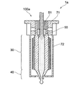
- the hot end 1a shown in FIG. 7 has a configuration in which a part of the supply portion 10 and the heat insulating portion 20 of the hot end 1 shown in FIG. 1 is removed. That is, the discharge head 100a constituting the hot end 1a is composed of a discharge portion 40, a melting portion 30, and a portion to which a metal member 71 which is a part of the heat insulating portion 20 in the hot end 1 is attached. In the hot end 1a as well, the backflow prevention member 50 is provided in the step portion of the passage 12 and is fixed by the retaining member 51 as in the hot end 1.
- a metal member 71 is provided on the outer periphery of the region of the hot end 100a where the backflow prevention member 50 is provided so that the filament held by the backflow prevention member 50 does not melt, and is further connected to the metal member 71.
- Case member 72 is provided.
- the side to which the hot end modeling material is supplied is inserted into the opening provided in the adapter attached to the 3D modeling apparatus main body side.
- the hot ends 1 and 1a of the present invention described above can be satisfactorily formed by using PEEK (polyetheretherketone) known as a super engineering plastic having a high heat resistant temperature as a filament.
- PEEK polyetheretherketone
- the backflow prevention member 50 suppresses the backflow of the melted modeling material, and the modeling operation is not defective due to clogging of the modeling material in the passage 12, and the operation is good.
- filaments of low melting point metals can also be used.
- the above-mentioned discharge head 100 has a length of about 33 mm as a whole, and the hot end 1 is much smaller than the existing hot end. Further, when the discharge head 100 is made of 64 titanium alloy, the weight is extremely reduced in combination with the small size. Therefore, even when the hot end 1 is moved to two dimensions or three dimensions to perform modeling, labor saving of driving energy can be achieved.
- the above-mentioned hot end 1a is further miniaturized than the hot end 1 because a part of the supply unit 10 and the heat insulating unit 20 is unnecessary. Further, since the hot ends 1 and 1a efficiently reuse the heat applied to the discharge heads 100 and 100a by the metal member 71 and the case member 72 for melting the filament, labor saving of melting energy can be achieved. It has been done.
- a titanium alloy for example, 64 titanium
- a ceramic substrate for example, an alumina zirconia substrate
- the alumina zirconia substrate can be made thinner because it has higher mechanical strength than the alumina substrate, and the size and weight of the heating head can be further reduced.
- the quadrangular prism-shaped melting portion 30 of the discharge heads 100 and 100a has four flat surfaces, the number of heating means 60 attached to the melting portion 30 and the attachment position of the heating means 60 can be determined. You can choose with a high degree of freedom. Further, when the temperature monitoring means (temperature sensor) is attached to the flat surface portion as needed, it can be easily attached to the flat surface portion.
- temperature monitoring means temperature sensor
- the backflow prevention member 50 has a shape in which the elasticity of the material is taken into consideration from the viewpoint of holding the filament with an appropriate force that does not hinder the feeding of the filament while adhering to the filament so that the backflow does not occur. It can be decided as appropriate.
Landscapes
- Engineering & Computer Science (AREA)
- Chemical & Material Sciences (AREA)
- Materials Engineering (AREA)
- Manufacturing & Machinery (AREA)
- Mechanical Engineering (AREA)
- Physics & Mathematics (AREA)
- Optics & Photonics (AREA)
- Press-Shaping Or Shaping Using Conveyers (AREA)
- Ink Jet (AREA)
Priority Applications (5)
| Application Number | Priority Date | Filing Date | Title |
|---|---|---|---|
| EP19942700.6A EP3970952B1 (en) | 2019-08-27 | 2019-08-27 | Deposition material hot end for 3d fabrication apparatus and 3d fabrication apparatus to which hot end is mounted |
| PCT/JP2019/033541 WO2021038721A1 (ja) | 2019-08-27 | 2019-08-27 | 3次元造形装置用の造形材料のホットエンド、及びホットエンドを搭載した3次元造形装置 |
| CN201980098152.0A CN114072271A (zh) | 2019-08-27 | 2019-08-27 | 用于三维造型装置的造型材料的热端、以及搭载热端的三维造型装置 |
| US17/637,880 US20220274319A1 (en) | 2019-08-27 | 2019-08-27 | Deposition material hot end for 3d fabrication apparatus and 3d fabrication apparatus to which hot end is mounted |
| JP2021541841A JP7025085B2 (ja) | 2019-08-27 | 2019-08-27 | 3次元造形装置用の造形材料のホットエンド、及びホットエンドを搭載した3次元造形装置 |
Applications Claiming Priority (1)
| Application Number | Priority Date | Filing Date | Title |
|---|---|---|---|
| PCT/JP2019/033541 WO2021038721A1 (ja) | 2019-08-27 | 2019-08-27 | 3次元造形装置用の造形材料のホットエンド、及びホットエンドを搭載した3次元造形装置 |
Publications (1)
| Publication Number | Publication Date |
|---|---|
| WO2021038721A1 true WO2021038721A1 (ja) | 2021-03-04 |
Family
ID=74683927
Family Applications (1)
| Application Number | Title | Priority Date | Filing Date |
|---|---|---|---|
| PCT/JP2019/033541 Ceased WO2021038721A1 (ja) | 2019-08-27 | 2019-08-27 | 3次元造形装置用の造形材料のホットエンド、及びホットエンドを搭載した3次元造形装置 |
Country Status (5)
| Country | Link |
|---|---|
| US (1) | US20220274319A1 (https=) |
| EP (1) | EP3970952B1 (https=) |
| JP (1) | JP7025085B2 (https=) |
| CN (1) | CN114072271A (https=) |
| WO (1) | WO2021038721A1 (https=) |
Cited By (1)
| Publication number | Priority date | Publication date | Assignee | Title |
|---|---|---|---|---|
| CN114043720A (zh) * | 2021-11-16 | 2022-02-15 | 深圳市洋明达科技有限公司 | 3d打印机打印头 |
Families Citing this family (3)
| Publication number | Priority date | Publication date | Assignee | Title |
|---|---|---|---|---|
| JP7476746B2 (ja) * | 2020-09-30 | 2024-05-01 | セイコーエプソン株式会社 | 三次元造形装置、及び、三次元造形システム |
| JP7491171B2 (ja) * | 2020-09-30 | 2024-05-28 | セイコーエプソン株式会社 | 三次元造形装置 |
| US20250196437A1 (en) * | 2023-12-19 | 2025-06-19 | Colin Bonathan LLC | Extreme performance scalable high strength hotend for fused filament fabrication systems |
Citations (4)
| Publication number | Priority date | Publication date | Assignee | Title |
|---|---|---|---|---|
| US5340433A (en) * | 1989-10-30 | 1994-08-23 | Stratasys, Inc. | Modeling apparatus for three-dimensional objects |
| JP2013511432A (ja) * | 2009-11-27 | 2013-04-04 | ロベルト・ボッシュ・ゲゼルシャフト・ミト・ベシュレンクテル・ハフツング | ピストンポンプ |
| JP2019069592A (ja) * | 2017-10-06 | 2019-05-09 | 株式会社ヒットリサーチ | 3dプリンタ用ヘッドモジュール、3dプリンタおよび造形方法 |
| KR20190075210A (ko) * | 2017-12-21 | 2019-07-01 | (주)재파트 | 도색기능을 가지는 3d 프린터용 노즐헤드 |
Family Cites Families (6)
| Publication number | Priority date | Publication date | Assignee | Title |
|---|---|---|---|---|
| US5480410A (en) * | 1994-03-14 | 1996-01-02 | Advanced Surgical, Inc. | Extracorporeal pneumoperitoneum access bubble |
| CN104405933B (zh) * | 2014-10-21 | 2016-10-05 | 江苏亿阀集团有限公司 | 一种基于记忆合金弹性元件的低温双瓣式止回阀 |
| DE102016006247A1 (de) * | 2016-05-20 | 2017-11-23 | Rüdiger Ufermann | ,,Anordnung zum laserinduzierten Aufschmelzen von Filamenten für 3D Drucker" |
| CN106915075B (zh) * | 2017-03-30 | 2023-08-04 | 西京学院 | 一种熔融沉积型3d打印机喷头冷却装置 |
| CN109094011B (zh) * | 2018-07-12 | 2021-03-12 | 杭州科技职业技术学院 | 一种适合聚醚醚酮的3d打印机头 |
| JP6635560B1 (ja) * | 2018-09-20 | 2020-01-29 | 谷口 秀夫 | 3次元造形装置用の造形材料のホットエンド、及びホットエンドを搭載した3次元造形装置 |
-
2019
- 2019-08-27 US US17/637,880 patent/US20220274319A1/en not_active Abandoned
- 2019-08-27 JP JP2021541841A patent/JP7025085B2/ja active Active
- 2019-08-27 CN CN201980098152.0A patent/CN114072271A/zh active Pending
- 2019-08-27 EP EP19942700.6A patent/EP3970952B1/en active Active
- 2019-08-27 WO PCT/JP2019/033541 patent/WO2021038721A1/ja not_active Ceased
Patent Citations (4)
| Publication number | Priority date | Publication date | Assignee | Title |
|---|---|---|---|---|
| US5340433A (en) * | 1989-10-30 | 1994-08-23 | Stratasys, Inc. | Modeling apparatus for three-dimensional objects |
| JP2013511432A (ja) * | 2009-11-27 | 2013-04-04 | ロベルト・ボッシュ・ゲゼルシャフト・ミト・ベシュレンクテル・ハフツング | ピストンポンプ |
| JP2019069592A (ja) * | 2017-10-06 | 2019-05-09 | 株式会社ヒットリサーチ | 3dプリンタ用ヘッドモジュール、3dプリンタおよび造形方法 |
| KR20190075210A (ko) * | 2017-12-21 | 2019-07-01 | (주)재파트 | 도색기능을 가지는 3d 프린터용 노즐헤드 |
Non-Patent Citations (2)
| Title |
|---|
| AZUO KADOTA: "Digital manufacturing starting with 3D printers", THE NIKKAN KOGYO SHIMBUN, LTD., pages: 103 |
| See also references of EP3970952A4 |
Cited By (1)
| Publication number | Priority date | Publication date | Assignee | Title |
|---|---|---|---|---|
| CN114043720A (zh) * | 2021-11-16 | 2022-02-15 | 深圳市洋明达科技有限公司 | 3d打印机打印头 |
Also Published As
| Publication number | Publication date |
|---|---|
| EP3970952A4 (en) | 2022-06-29 |
| EP3970952B1 (en) | 2023-08-02 |
| CN114072271A (zh) | 2022-02-18 |
| EP3970952A1 (en) | 2022-03-23 |
| JPWO2021038721A1 (https=) | 2021-03-04 |
| JP7025085B2 (ja) | 2022-02-24 |
| US20220274319A1 (en) | 2022-09-01 |
Similar Documents
| Publication | Publication Date | Title |
|---|---|---|
| JP7025085B2 (ja) | 3次元造形装置用の造形材料のホットエンド、及びホットエンドを搭載した3次元造形装置 | |
| JP6509417B2 (ja) | 造形材料吐出ヘッド、造形材料吐出ヘッドを備えた3次元プリンタ、造形材料吐出ヘッドの流路構造体、および造形材料吐出ヘッドの流路の形成方法 | |
| US12030224B2 (en) | High dynamic temperature control system | |
| US20150147427A1 (en) | Extrusion heads | |
| KR101946931B1 (ko) | 전자 부품의 시험 장치 | |
| JPWO2019155611A1 (ja) | 3次元造形装置用の造形材料の吐出ヘッド | |
| JP6635560B1 (ja) | 3次元造形装置用の造形材料のホットエンド、及びホットエンドを搭載した3次元造形装置 | |
| JP6454814B1 (ja) | 3dプリンタ用ヘッドモジュール、3dプリンタおよび造形方法 | |
| JP4744858B2 (ja) | インク装填装置の溶融アセンブリ | |
| JP2018001505A (ja) | 造形材料の吐出ヘッドおよび造形方法 | |
| JP6566535B1 (ja) | 3次元造形装置用の造形材料のホットエンド | |
| EP1413418A1 (en) | Apparatus for heating injection molding fluid | |
| CN112122612A (zh) | 一种螺杆挤出式3d打印机用电磁加热装置 | |
| JP2015120334A (ja) | インパルスシーラーのセラミックスでカバーされたヒーター | |
| JP6454810B1 (ja) | 3次元造形装置用のホットエンド | |
| JP6942373B2 (ja) | 3次元造形装置用のホットエンド、及びホットエンドを搭載した3次元プリンタ | |
| JP6420521B1 (ja) | 3次元造形装置用の造形材料の吐出ヘッド及び3次元造形装置 | |
| JP6937051B2 (ja) | 3次元プリンタ及びこれを用いた造形方法 | |
| JP2005178373A (ja) | インク装填装置のドリッププレート | |
| TWI640218B (zh) | Injection molding machine and its variable power type heating sheet | |
| EP4275528A1 (en) | Heating component of an electronic atomization device | |
| CN223099968U (zh) | 喷头结构及应用其的喷头套件和3d打印设备 | |
| Taniguchi et al. | Application Kaizen for FDM 3D High Temp (500 C) Hotend | |
| JP2021003820A (ja) | 3次元プリンタ、3次元プリンタ用モジュール装置、及び立体造形物の造形方法 | |
| CZ2019103A3 (cs) | Zařízení pro tepelné spojování dílů z plastů nýtováním |
Legal Events
| Date | Code | Title | Description |
|---|---|---|---|
| 121 | Ep: the epo has been informed by wipo that ep was designated in this application |
Ref document number: 19942700 Country of ref document: EP Kind code of ref document: A1 |
|
| ENP | Entry into the national phase |
Ref document number: 2019942700 Country of ref document: EP Effective date: 20211217 |
|
| ENP | Entry into the national phase |
Ref document number: 2021541841 Country of ref document: JP Kind code of ref document: A |
|
| NENP | Non-entry into the national phase |
Ref country code: DE |