WO2021033633A1 - 有機物ナノ粒子の製造方法及び有機物ナノ粒子 - Google Patents
有機物ナノ粒子の製造方法及び有機物ナノ粒子 Download PDFInfo
- Publication number
- WO2021033633A1 WO2021033633A1 PCT/JP2020/030862 JP2020030862W WO2021033633A1 WO 2021033633 A1 WO2021033633 A1 WO 2021033633A1 JP 2020030862 W JP2020030862 W JP 2020030862W WO 2021033633 A1 WO2021033633 A1 WO 2021033633A1
- Authority
- WO
- WIPO (PCT)
- Prior art keywords
- slurry
- beads
- stirring rotor
- bead
- bead mill
- Prior art date
Links
Images


Classifications
-
- C—CHEMISTRY; METALLURGY
- C07—ORGANIC CHEMISTRY
- C07D—HETEROCYCLIC COMPOUNDS
- C07D233/00—Heterocyclic compounds containing 1,3-diazole or hydrogenated 1,3-diazole rings, not condensed with other rings
- C07D233/54—Heterocyclic compounds containing 1,3-diazole or hydrogenated 1,3-diazole rings, not condensed with other rings having two double bonds between ring members or between ring members and non-ring members
- C07D233/66—Heterocyclic compounds containing 1,3-diazole or hydrogenated 1,3-diazole rings, not condensed with other rings having two double bonds between ring members or between ring members and non-ring members with hetero atoms or with carbon atoms having three bonds to hetero atoms with at the most one bond to halogen, e.g. ester or nitrile radicals, directly attached to ring carbon atoms
- C07D233/72—Two oxygen atoms, e.g. hydantoin
- C07D233/74—Two oxygen atoms, e.g. hydantoin with only hydrogen atoms or radicals containing only hydrogen and carbon atoms, attached to other ring members
-
- A—HUMAN NECESSITIES
- A61—MEDICAL OR VETERINARY SCIENCE; HYGIENE
- A61K—PREPARATIONS FOR MEDICAL, DENTAL OR TOILETRY PURPOSES
- A61K9/00—Medicinal preparations characterised by special physical form
- A61K9/48—Preparations in capsules, e.g. of gelatin, of chocolate
- A61K9/50—Microcapsules having a gas, liquid or semi-solid filling; Solid microparticles or pellets surrounded by a distinct coating layer, e.g. coated microspheres, coated drug crystals
- A61K9/51—Nanocapsules; Nanoparticles
- A61K9/5192—Processes
-
- A—HUMAN NECESSITIES
- A61—MEDICAL OR VETERINARY SCIENCE; HYGIENE
- A61K—PREPARATIONS FOR MEDICAL, DENTAL OR TOILETRY PURPOSES
- A61K31/00—Medicinal preparations containing organic active ingredients
- A61K31/185—Acids; Anhydrides, halides or salts thereof, e.g. sulfur acids, imidic, hydrazonic or hydroximic acids
- A61K31/19—Carboxylic acids, e.g. valproic acid
- A61K31/195—Carboxylic acids, e.g. valproic acid having an amino group
- A61K31/196—Carboxylic acids, e.g. valproic acid having an amino group the amino group being directly attached to a ring, e.g. anthranilic acid, mefenamic acid, diclofenac, chlorambucil
-
- A—HUMAN NECESSITIES
- A61—MEDICAL OR VETERINARY SCIENCE; HYGIENE
- A61K—PREPARATIONS FOR MEDICAL, DENTAL OR TOILETRY PURPOSES
- A61K31/00—Medicinal preparations containing organic active ingredients
- A61K31/21—Esters, e.g. nitroglycerine, selenocyanates
- A61K31/215—Esters, e.g. nitroglycerine, selenocyanates of carboxylic acids
- A61K31/216—Esters, e.g. nitroglycerine, selenocyanates of carboxylic acids of acids having aromatic rings, e.g. benactizyne, clofibrate
-
- A—HUMAN NECESSITIES
- A61—MEDICAL OR VETERINARY SCIENCE; HYGIENE
- A61K—PREPARATIONS FOR MEDICAL, DENTAL OR TOILETRY PURPOSES
- A61K31/00—Medicinal preparations containing organic active ingredients
- A61K31/33—Heterocyclic compounds
- A61K31/395—Heterocyclic compounds having nitrogen as a ring hetero atom, e.g. guanethidine or rifamycins
- A61K31/41—Heterocyclic compounds having nitrogen as a ring hetero atom, e.g. guanethidine or rifamycins having five-membered rings with two or more ring hetero atoms, at least one of which being nitrogen, e.g. tetrazole
- A61K31/4164—1,3-Diazoles
- A61K31/4166—1,3-Diazoles having oxo groups directly attached to the heterocyclic ring, e.g. phenytoin
-
- A—HUMAN NECESSITIES
- A61—MEDICAL OR VETERINARY SCIENCE; HYGIENE
- A61K—PREPARATIONS FOR MEDICAL, DENTAL OR TOILETRY PURPOSES
- A61K31/00—Medicinal preparations containing organic active ingredients
- A61K31/33—Heterocyclic compounds
- A61K31/395—Heterocyclic compounds having nitrogen as a ring hetero atom, e.g. guanethidine or rifamycins
- A61K31/41—Heterocyclic compounds having nitrogen as a ring hetero atom, e.g. guanethidine or rifamycins having five-membered rings with two or more ring hetero atoms, at least one of which being nitrogen, e.g. tetrazole
- A61K31/42—Oxazoles
-
- A—HUMAN NECESSITIES
- A61—MEDICAL OR VETERINARY SCIENCE; HYGIENE
- A61K—PREPARATIONS FOR MEDICAL, DENTAL OR TOILETRY PURPOSES
- A61K31/00—Medicinal preparations containing organic active ingredients
- A61K31/33—Heterocyclic compounds
- A61K31/395—Heterocyclic compounds having nitrogen as a ring hetero atom, e.g. guanethidine or rifamycins
- A61K31/495—Heterocyclic compounds having nitrogen as a ring hetero atom, e.g. guanethidine or rifamycins having six-membered rings with two or more nitrogen atoms as the only ring heteroatoms, e.g. piperazine or tetrazines
- A61K31/496—Non-condensed piperazines containing further heterocyclic rings, e.g. rifampin, thiothixene
-
- A—HUMAN NECESSITIES
- A61—MEDICAL OR VETERINARY SCIENCE; HYGIENE
- A61K—PREPARATIONS FOR MEDICAL, DENTAL OR TOILETRY PURPOSES
- A61K31/00—Medicinal preparations containing organic active ingredients
- A61K31/63—Compounds containing para-N-benzenesulfonyl-N-groups, e.g. sulfanilamide, p-nitrobenzenesulfonyl hydrazide
- A61K31/635—Compounds containing para-N-benzenesulfonyl-N-groups, e.g. sulfanilamide, p-nitrobenzenesulfonyl hydrazide having a heterocyclic ring, e.g. sulfadiazine
-
- B—PERFORMING OPERATIONS; TRANSPORTING
- B02—CRUSHING, PULVERISING, OR DISINTEGRATING; PREPARATORY TREATMENT OF GRAIN FOR MILLING
- B02C—CRUSHING, PULVERISING, OR DISINTEGRATING IN GENERAL; MILLING GRAIN
- B02C17/00—Disintegrating by tumbling mills, i.e. mills having a container charged with the material to be disintegrated with or without special disintegrating members such as pebbles or balls
- B02C17/16—Mills in which a fixed container houses stirring means tumbling the charge
-
- B—PERFORMING OPERATIONS; TRANSPORTING
- B02—CRUSHING, PULVERISING, OR DISINTEGRATING; PREPARATORY TREATMENT OF GRAIN FOR MILLING
- B02C—CRUSHING, PULVERISING, OR DISINTEGRATING IN GENERAL; MILLING GRAIN
- B02C17/00—Disintegrating by tumbling mills, i.e. mills having a container charged with the material to be disintegrated with or without special disintegrating members such as pebbles or balls
- B02C17/18—Details
- B02C17/20—Disintegrating members
-
- B—PERFORMING OPERATIONS; TRANSPORTING
- B02—CRUSHING, PULVERISING, OR DISINTEGRATING; PREPARATORY TREATMENT OF GRAIN FOR MILLING
- B02C—CRUSHING, PULVERISING, OR DISINTEGRATING IN GENERAL; MILLING GRAIN
- B02C17/00—Disintegrating by tumbling mills, i.e. mills having a container charged with the material to be disintegrated with or without special disintegrating members such as pebbles or balls
- B02C17/18—Details
- B02C17/24—Driving mechanisms
-
- B—PERFORMING OPERATIONS; TRANSPORTING
- B82—NANOTECHNOLOGY
- B82Y—SPECIFIC USES OR APPLICATIONS OF NANOSTRUCTURES; MEASUREMENT OR ANALYSIS OF NANOSTRUCTURES; MANUFACTURE OR TREATMENT OF NANOSTRUCTURES
- B82Y40/00—Manufacture or treatment of nanostructures
-
- C—CHEMISTRY; METALLURGY
- C07—ORGANIC CHEMISTRY
- C07D—HETEROCYCLIC COMPOUNDS
- C07D261/00—Heterocyclic compounds containing 1,2-oxazole or hydrogenated 1,2-oxazole rings
- C07D261/02—Heterocyclic compounds containing 1,2-oxazole or hydrogenated 1,2-oxazole rings not condensed with other rings
- C07D261/06—Heterocyclic compounds containing 1,2-oxazole or hydrogenated 1,2-oxazole rings not condensed with other rings having two or more double bonds between ring members or between ring members and non-ring members
- C07D261/10—Heterocyclic compounds containing 1,2-oxazole or hydrogenated 1,2-oxazole rings not condensed with other rings having two or more double bonds between ring members or between ring members and non-ring members with hetero atoms or with carbon atoms having three bonds to hetero atoms with at the most one bond to halogen, e.g. ester or nitrile radicals, directly attached to ring carbon atoms
- C07D261/14—Nitrogen atoms
- C07D261/16—Benzene-sulfonamido isoxazoles
-
- C—CHEMISTRY; METALLURGY
- C07—ORGANIC CHEMISTRY
- C07D—HETEROCYCLIC COMPOUNDS
- C07D405/00—Heterocyclic compounds containing both one or more hetero rings having oxygen atoms as the only ring hetero atoms, and one or more rings having nitrogen as the only ring hetero atom
- C07D405/14—Heterocyclic compounds containing both one or more hetero rings having oxygen atoms as the only ring hetero atoms, and one or more rings having nitrogen as the only ring hetero atom containing three or more hetero rings
-
- A—HUMAN NECESSITIES
- A61—MEDICAL OR VETERINARY SCIENCE; HYGIENE
- A61K—PREPARATIONS FOR MEDICAL, DENTAL OR TOILETRY PURPOSES
- A61K9/00—Medicinal preparations characterised by special physical form
- A61K9/48—Preparations in capsules, e.g. of gelatin, of chocolate
- A61K9/50—Microcapsules having a gas, liquid or semi-solid filling; Solid microparticles or pellets surrounded by a distinct coating layer, e.g. coated microspheres, coated drug crystals
- A61K9/5089—Processes
Definitions
- the present disclosure relates to a method for producing organic nanoparticles using a wet bead mill.
- the present disclosure particularly relates to a method for producing nanoparticles of a poorly soluble pharmaceutical compound.
- a crushing process using a jet mill or a bead mill is common.
- the pulverization treatment with a wet bead mill is often performed, and is generally performed as follows.
- a mixture (slurry) of the chemical raw material powder and the dispersion medium prepared in several to several tens of micrometers is prepared and supplied to a bead mill containing a spherical pulverized medium (beads).
- Beads spherical pulverized medium
- the mixture of the slurry and the beads is stirred, and the chemical raw material powder is pulverized.
- an inorganic substance such as zirconia, alumina, hard glass, or silicon carbide, or a polymer material such as polystyrene or polypropylene is used.
- Patent Document 1 describes that the size of beads used for nanomilling is preferably 3 mm or less, more preferably 1 mm or less, and Patent Document 2 uses beads of 10 to 1000 micrometers. It is described that by doing so, even finer particles are pulverized.
- Patent Document 3 describes that it is desirable to use beads of less than 500 micrometers in the pulverization treatment. However, Patent Documents 1 to 3 merely describe the appropriate bead diameter, and do not specifically describe the conditions of the pulverization treatment.
- Patent Document 4 beads of 20 to 200 micrometers are used, and a bead mill device provided with a stirring rotor having a special shape is driven so that the outer peripheral speed of the stirring rotor is 3 to 8 m / sec to perform a crushing process. It is stated that it should be done.
- Patent Document 4 does not describe mixing of debris generated from beads or a stirring rotor into the slurry.
- the crushing efficiency can be improved by using a stirring rotor having a special shape, but the contact area between the beads and the stirring rotor member is increased and a high-speed flow is locally formed. Therefore, the mixing of beads and debris of the stirring rotor member into the slurry can be increased.
- a permissible concentration is set for the content of a substance that may be harmful to health, and this is also applied to nanopharmaceuticals.
- the nano-drug there is a problem that the components are mixed in the drug as the beads and the members of the mill are worn in the pulverization process.
- elements such as zirconium, yttrium, aluminum and silicon, which are components of beads, and elements such as iron, nickel, chromium and tungsten, which are components of metal parts of the mill, are mixed in the chemicals. obtain.
- Patent Document 5 describes that it is desirable that the amount of heavy metals mixed in is less than about 10 ppm in the production of pharmaceutical products, but it is difficult to achieve this by the pulverization treatment using beads.
- Patent Document 5 describes that beads coated with a polymer resin are used as a pulverization medium as a method for reducing the mixture of metallic substances in nano-sized pulverized organic substances. However, even if the mixing of metallic substances from beads can be suppressed, there is a risk that polymer resins will be mixed. Furthermore, metal substances may be mixed in from the parts of the bead mill device, but no solution to this is described.
- a stirring rotor that rotates a mixture containing a slurry containing organic particles and beads having an average particle size of 0.15 mm to 0.9 mm at an outer peripheral speed of 7 m / sec or less in a container of a wet bead mill.
- Method for producing organic nanoparticles including the step of stirring with (2) In the container of the wet bead mill, the slurry containing the organic particles and the value calculated by 0.15 mm or more and 1.07-0.11 ⁇ [outer peripheral speed of the stirring rotor (m / sec)] (
- a method for producing organic nanoparticles which comprises a step of stirring a mixture containing beads having an average particle size of mm) or less with a stirring rotor rotating at an outer peripheral speed of 7 m / sec or less.
- a method for producing organic nanoparticles which comprises a step of stirring a mixture containing a slurry containing organic particles and beads in a container of a wet bead mill with a stirring rotor, wherein the container of the wet bead mill is a vertical type.
- the cylindrical container is provided with an opening at the top of the cylindrical container, and a rotating shaft for rotating the stirring rotor is inserted into the cylindrical container from above the cylindrical container via the opening.
- a manufacturing method, wherein the stirring rotor is connected to the rotating shaft.
- organic powder such as a pharmaceutical compound
- nanoparticles for example, an average particle size of 400 nanometers or less
- contaminants from beads and bead mill parts can be reduced.
- the method of the present disclosure can prevent contamination not only in pharmaceutical products but also in the production of nanoparticles such as health foods and X-ray contrast media.
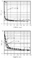
- the time change of the average particle diameter (D50) of the organic powder (phenytoin) in the pulverization treatment is shown.
- the upper graph shows the results using beads with a small particle size ( ⁇ : bead diameter 0.1 mm, ⁇ : bead diameter 0.2 mm, ⁇ : bead diameter 0.3 mm), and the lower graph shows the particle size. This is the result of using large beads ( ⁇ : bead diameter 0.5 mm, ⁇ : bead diameter 0.8 mm, ⁇ : bead diameter 1.0 mm).
- the time change of the contaminant concentration (total concentration of zirconium and yttrium in the slurry: ZY concentration (ppm)) in the pulverization treatment of the organic powder (phenytoin) is shown.
- the effect of the outer peripheral speed (outer peripheral speed) of the stirring rotor on the pulverization processing time is shown.
- ⁇ Bead diameter 0.2 mm, ⁇ : Bead diameter 0.3 mm, ⁇ : Bead diameter 0.5 mm, ⁇ : Bead diameter 0.8 mm.
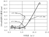
- the effect of the outer peripheral speed (outer peripheral speed) of the stirring rotor on the concentration of contaminants is shown.
- ⁇ Bead diameter 0.2 mm, ⁇ : Bead diameter 0.3 mm, ⁇ : Bead diameter 0.5 mm.
- the effect of bead diameter on contaminant concentration is shown.
- ⁇ Outer peripheral speed 2 m / sec, ⁇ : Outer peripheral speed 4 m / sec, ⁇ : Outer peripheral speed 6 m / sec.
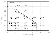
- the relationship between the bead diameter and the outer peripheral speed (outer peripheral speed) of the stirring rotor under suitable pulverization conditions is shown.
- the average particle size is obtained from the particle size distribution measured by a particle size distribution measuring machine, and is expressed as a volume-based median diameter (D50).
- D50 volume-based median diameter
- the value obtained by measuring with LA-950 manufactured by HORIBA, Ltd. is described as the average particle size. If it is a static laser diffraction / scattering type particle size analyzer, almost the same measurement results can be obtained.
- particle size and particle size used in the present specification have the same meaning as the above "average particle size”.
- the "slurry” is a suspension of solid particles of an organic substance of about 100 micrometers or less in a liquid dispersion medium.
- a slurry can be prepared using organic particles having an average particle size of 1 to 100 micrometers, but the method of the present disclosure can be carried out even if the slurry has an average particle size of 100 micrometers or more.
- the pulverization processing speed up to a particle size of 5 micrometers or more is extremely fast, for example, the pulverization processing time from 30 micrometers to 5 micrometers is about 3 minutes, and the entire pulverization is performed. Very short compared to the processing time of 45-400 minutes.
- the influence of the particle size of the organic substance before the pulverization treatment on the operating conditions of the bead mill is small.
- the particle size of the organic particles in the raw material slurry before the pulverization treatment is preferably 1 to 100 micrometers, but if it is 1 ⁇ m or more, there is no substantial effect on the setting of the operating conditions.
- the dispersion medium used in the method of the present disclosure is not particularly limited as long as it is a liquid medium in which the pulverized organic particles are essentially insoluble, and those skilled in the art will appropriately select the dispersion medium according to the properties of the organic particles. be able to.
- water or various organic solvents eg, alcohols such as methanol, ethanol, isopropanol, butanol, ketones such as acetone, methyl ethyl ketone, methyl propyl ketone, methyl isobutyl ketone, ethers such as isopropyl ether, methyl cellosolve, ethylene glycol, Glycol esters such as propylene glycol monomethyl ether acetate and ethylene glycol monoethyl ether acetate, esters such as ethyl acetate, halogenated hydrocarbons such as methylene chloride and trichloroethane, non-aromatic hydrocarbons such as cyclohexane, and aromatic hydrocarbons such as toluene. , Linear hydrocarbons such as normal hexane, etc.).
- organic solvents eg, alcohols such as methanol, ethanol, isopropanol, butanol, ketones such
- the "organic particle” may be any solid particle containing an organic compound, for example, an electronic component.
- examples include, but are not limited to, particles of any organic compound used in various fields such as materials, phosphors, pigments, paints, pharmaceuticals, pesticides, foods and the like.
- organic particles used in the field of pharmaceuticals include, but are not limited to, pharmaceutical compounds used as active ingredients of pharmaceuticals, additives used in pharmaceutical preparations, and those used in the production of X-ray contrast media. ..
- the pharmaceutical compound is not particularly limited, and any compound can be used.
- any compound can be used.
- Examples include, but are not limited to, fervinac, diferonac, acemetacin, alcrophenac, fembufen, lobenzalit, peniciramine, naproxen, pranoprofen, etodolac, cyclosporin, and the like.
- the concentration of organic particles in the slurry is not particularly limited as long as the concentration can obtain fluidity that can be pulverized by a bead mill.
- the slurry concentration is shown as% by weight of the object to be pulverized (organic particles) with respect to the weight of the entire slurry.
- the slurry concentration used in the method of the present disclosure is, for example, an arbitrary concentration in the range of 1 to 70% by weight, 2 to 65% by weight, 3 to 60% by weight, 4 to 55% by weight, and 5 to 50% by weight. Can be mentioned.
- organic nanoparticles refers to the above-mentioned organic particles as having a nanometer size with an average particle size of less than 1 nanometer, for example, an average particle size of 500 nanometers or less, 400 nanometers or less, 300 nanometers or less. It means particles obtained by crushing to 200 nanometers or less, 100 nanometers or less, 50 nanometers or less, and 20 nanometers or less (also referred to as “nano crushing” in the present specification).
- the organic particles are pulverized by rotating the stirring rotor fixed to the rotating shaft in the container of the wet bead mill and stirring the mixture of the slurry and the beads.
- the container of the wet bead mill that can be used in the method of the present disclosure has an inner wall surface forming a point-symmetrical circle with respect to the central axis, and the diameter of the inner wall surface is constant in the direction parallel to the central axis. May also change. In addition, there may be a portion that is not point-symmetrical due to a slurry supply port or the like.
- the wet bead mill that can be used in the method of the present disclosure is for stirring a mixture of beads and slurry in a container such as reinforced alumina, silicon carbide, Sialon (SiAlON), partially stabilized zirconia, and stainless steel.
- the outside of the container may be water-cooled as a jacket structure.
- the capacity of the wet bead mill that can be used in the method of the present disclosure is a capacity generally used in the art, for example, any capacity of 0.15 L to 10 L (0.15 L, 0.5 L, 1 L). , 2L, 5L, 10L, etc.).
- stirring rotor one made of hard ceramics such as reinforced alumina, silicon carbide, sialon, and partially stabilized zirconia can be used, but a stirring rotor made of partially stabilized zirconia is preferable.
- partially stabilized zirconia contains 4 to 6% by weight of ytttrium oxide as an additive with respect to 94 to 96% by weight of zirconium oxide, and another oxide is added in addition to this. ..
- the partially stabilized zirconia has high toughness as well as strength, and local defects are unlikely to occur. Therefore, the stirring rotor made of partially stabilized zirconia has an advantage that less debris is generated.
- the method of the present disclosure can be carried out using, for example, a wet bead mill device as shown in FIGS. 1 to 4, but the device is not limited to these devices and is generally used in the art. Can be carried out using.
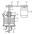
- the bead mill used in the method of the present disclosure is a vertical bead mill (device 1) of the type shown in FIG. 1, in which the slurry is supplied from the upper part and discharged from the lower part.
- the container of the bead mill is a vertical cylindrical container, which has an opening at the top, and a rotary shaft 4 connected to a drive device such as a rotary shaft pulley 9 is inserted into the cylindrical container from above the cylindrical container via the opening. It is inserted in the vertical direction, and a stirring rotor 5 is connected to the rotating shaft 4.
- a mechanical seal 13 is installed at the connection portion between the rotating shaft 4 and the cylindrical container. The slurry flows from the top to the bottom, separates the beads by the slit type bead separator 8, and then is discharged from the lower part of the cylindrical container.
- the bead mill used in the method of the present disclosure is a vertical bead mill (device 2) of the type shown in FIG. 2, in which the slurry is supplied from the lower part and discharged from the upper part.
- the container of the bead mill is a vertical cylindrical container, which has an opening at the top of the cylindrical container, and a rotating shaft 4 connected to a drive device such as a rotating shaft pulley 9 is cylindrical from above the cylindrical container via the opening. It is inserted vertically into the container.
- a stirring rotor 5 and a centrifugal bead separating device 14 are connected to the rotating shaft 4.
- Two mechanical seals 13 are installed at the connecting portion of the cylindrical container. After the beads are separated by the centrifugal bead separating device 14, the slurry rises in the hollow flow path installed in the rotating shaft and is discharged from the discharge port 7.
- the wet bead mill device is generally provided with a mechanical seal or a similar sealing device for the purpose of sealing between the rotating shaft and the cylindrical container.
- a mechanical seal or a similar sealing device for the purpose of sealing between the rotating shaft and the cylindrical container.
- the material of the contact portion between the rotating portion and the fixing portion of the mechanical seal include high-strength metals such as iron, nickel, molybdenum, tungsten, chromium, and silicon, and high-strength ceramics, and a sealing device during crushing with a bead mill. These can be mixed into the slurry as the ceramic wears. Therefore, the concentration of contaminants can be further reduced by pulverizing the organic powder using a bead mill without a sealing device.
- a vertical cylindrical container is used, and a through hole is provided on the upper surface of the cylindrical container, and the rotating shaft is moved from above the cylindrical container through the through hole.
- a structure that is inserted into the cylindrical container and has a stirring rotor connected to the rotating shaft can be mentioned.
- a mechanism for supplying and discharging the slurry into the cylindrical container without a mechanical seal of the rotating portion is required. As an embodiment, an example of such a device is shown in FIG.
- the bead mill (device 3) of FIG. 3 has the same structure and capacity as the above device 1, but has an open connection between the rotating shaft and the cylindrical container, and is a circulation type wet bead mill without a sealing device.
- a rotary shaft 4 connected to a drive device such as a rotary shaft pulley 9 is vertically inserted into a cylindrical container via a slurry storage tank 15 and a connecting pipe line 16.
- a stirring rotor 5 is connected to the rotating shaft 4.
- the slurry flows from the circulation tank 20 into the slurry storage tank 15 via the slurry connecting pipe 22, and further flows into the cylindrical container via the connecting pipe 16.
- the slurry pulverized while descending in the cylindrical container is discharged to the outside of the cylindrical container from the slurry discharge port 7 after the beads are separated by the plug-type bead separator 8.
- the slurry is further returned to the circulation tank 20 by the pump 19 via the slurry pipe 18.
- a pumping device 17 may be installed on the rotating shaft 4 in the connecting pipe 16 to push the slurry downward.
- bead mills without other types of sealing devices can be applied to the method of the present disclosure.
- examples of other types of bead mills have the following structures. There is a slurry storage tank above the cylindrical container, and a through hole connecting the cylindrical container and the slurry storage tank is installed, and a rotation shaft extends into the cylindrical container through the through hole, and a stirring rotor is provided there. Is connected to.
- the rotating shaft in the through hole has a structure in which the slurry is flowed from the slurry storage tank to the cylindrical container by a pumping mechanism for circulation, a blade for turning the slurry, and the like. This flow can prevent beads from leaking through the through holes.
- the slurry flowing downward through the through hole returns to the slurry storage tank via the centrifugal bead separating device and the hollow flow path.
- the stirring rotor has a plurality of rod-shaped pins installed, but the stirring rotor has a plurality of horizontally arranged disks installed in the height direction.
- a plurality of plate-shaped objects installed in the vertical direction may be used.
- the rotation speed of the stirring rotor is relatively slow, so that the bead mill used is preferably a vertical bead mill.
- centrifugal force acts in the direction perpendicular to gravity, and the force applied to the beads is almost constant in the circumferential direction inside the cylindrical container, so there is no local excessive force acting and it is uniform. High sex.
- the flow direction of the slurry in the cylindrical container of the bead mill may be either an upward flow or a downward flow, but by flowing the slurry downward, the beads can be filled downward, and the beads can be filled together at the bottom of the cylindrical container. Since the contact frequency is improved, it is more preferable to use a vertical bead mill such as the device 1 or the device 3 in which the slurry flows from the top to the bottom. However, since the flow speed of the slurry in the vertical direction is low, the difference is small, and the method of the present disclosure can also be carried out by using a vertical bead mill in which the slurry flows from the bottom to the top.
- the method of the present disclosure can be implemented even with a horizontal bead mill.
- An example of the horizontal bead mill is the bead mill (device 4) shown in FIG.
- the rotation shaft 4 is installed in the horizontal direction, and a plurality of petal-shaped and perforated stirring rotors 5 installed in parallel with the rotation direction are installed, and the stirring rotor 5 stirs the slurry and beads. To do.
- the treated slurry is discharged out of the cylindrical container after the beads are separated by the screen 23.
- the directions of centrifugal force and gravity differ depending on the position in the circumferential direction in the cylindrical container. At the upper part of the side surface of the cylindrical container, gravity is subtracted from the centrifugal force, and the force for pressing the beads is weakened. On the other hand, in the lower part, the centrifugal force and the gravity are combined, so that the force for pressing the beads becomes stronger.
- the method of the present disclosure is carried out under the condition that the outer peripheral speed of the stirring rotor (also referred to as "outer peripheral speed" in the present specification) is relatively slow and the centrifugal force is small, the degree of the above-mentioned phenomenon is large and the beads Is difficult to rise to the top of the cylindrical container, which slows down the processing speed. Therefore, in the horizontal bead mill, when the outer peripheral speed is particularly low, the concentration of contaminants is slightly increased as compared with the vertical bead mill, but it can be used in the method of the present disclosure.
- the slurry treatment time per circulation is 3 to 10 minutes, and the circulation treatment is generally performed about 5 to 50 times.
- the general processing time is 30 to 400 minutes, but it may be shorter or longer depending on the capacity of the mill.
- the beads used in the method of the present disclosure are not particularly limited as long as they are usually used for pulverization treatment using a wet bead mill, and those skilled in the art can use the specifications of the bead mill and the characteristics of the object to be pulverized (for example, particles). It can be appropriately selected in consideration of various factors such as hardness, density and particle size), target particle size of fine particles after pulverization, viscosity of slurry and the like.
- bead material used in the bead mill examples include, but are not limited to, glass, alumina, zircon (zirconia-silica ceramics), zirconia, and steel.
- Zirconia is preferable as a material for beads because it has a high hardness and tends to have less debris mixed due to bead deterioration.
- beads made of partially stabilized zirconia are particularly preferable because, as described above, not only strength but also toughness is high and local defects are unlikely to occur.
- partially stabilized zirconia beads are used in the method of the present disclosure.
- beads made of partially stabilized zirconia may be simply referred to as "beads”.
- the "bead filling rate” is the apparent volume (% by volume) of the beads with respect to the effective volume of the cylindrical container of the bead mill (the internal volume of the cylindrical container minus the volume of the stirring rotor).
- a person skilled in the art can appropriately select the bead filling rate in consideration of various factors such as the specifications and operating conditions of the bead mill and the viscosity of the slurry. Generally, it can be appropriately set within the range of 10 to 95% by volume, for example, 15 to 95% by volume, 25 to 90% by volume, 35 to 90% by volume, 50 to 90% by volume, 75 to 90% by volume. It can be set within the range of%.
- the amount of slurry charged into the bead mill can be appropriately selected by those skilled in the art according to the specifications of the bead mill (for example, the capacity of the crushing chamber of the bead mill to be used), operating conditions, and the like.
- the average particle size of beads (also referred to as "bead diameter" in the present specification). ) May be relatively small. Further, the smaller the particle size of the beads, the larger the specific surface area and the faster the pulverization rate. In general, bead wear has two factors, a wear increasing factor due to the specific surface area of the beads and a wear increasing factor due to the mass of a single substance. The former has less wear as the particle size of the beads is larger, and the latter has less wear as the particle size of the beads is smaller. Considering both, it is considered that the bead diameter of the intermediate size has less wear.
- beads having an arbitrary average particle size in the range of 0.15 mm to 0.9 mm can be used, for example, particle size standards 0.15 mm, 0.2 mm, 0.3 mm, 0.
- Commercially available beads as .4 mm, 0.5 mm, 0.6 mm, 0.7 mm, 0.8 mm, or 0.9 mm can be used.
- the surface area of beads is overwhelmingly larger than the surface area of bead mill members.
- the effective internal volume 200 ml the total area of the stirring rotor and the cylindrical inner surface of the container in the range of about 10 5 mm 2
- the total surface area of the beads are of 10 6 ⁇ 10 7 mm 2 orders
- the wear caused by the contact between the beads is overwhelmingly larger than the wear of the members of the bead mill. Therefore, the method of the present disclosure that suppresses the wear of beads varies depending on the shape of the stirring rotor, and the minimum value of the contaminant concentration that can be achieved differs, but in principle, it can be applied to stirring rotors of all shapes and has a complicated shape. Even with a stirring rotor, the effect of the method of the present disclosure can be expected.
- the stirring rotor of the wet bead mill used in the method of the present disclosure includes a stirring rotor in which rod-shaped pins are installed at point-symmetrical positions with respect to the rotation direction, and a stirring rotor composed of a plurality of plates parallel to the rotation direction.
- the pin-shaped stirring rotor does not necessarily have to have a columnar shape, may have a plate shape, or may not have a simple plate shape.
- the "outer peripheral speed” or “outer peripheral speed” means the outer peripheral speed of the stirring rotor during rotation. Under the same bead diameter conditions, the faster the outer peripheral speed of the stirring rotor, the shorter the processing time. In the method of the present disclosure, an outer peripheral speed of 1 m / sec or more is preferable, but even if the outer peripheral speed is 0.5 m / sec, the organic particles can be pulverized to a particle size of about 200 nanometers. The outer peripheral speed of the stirring rotor also affects the wear of the beads and the stirring rotor member.
- the outer peripheral speed of the stirring rotor when the outer peripheral speed of the stirring rotor is 7 m / sec or less, a sufficient processing speed can be maintained and the concentration of contaminants from beads and the stirring rotor member can be significantly suppressed.
- the outer peripheral speed of the stirring rotor in the method of the present disclosure is, for example, an arbitrary speed within the range of 0.5 m / sec to 7 m / sec (for example, 0.5 m / sec, 1 m / sec, 2 m / sec, 3 m / sec). Seconds, 4 m / sec, 5 m / sec, 6 m / sec, 7 m / sec).
- the outer peripheral speed of the stirring rotor is 7 m / sec or less, 0.15 mm or more, and 1.07 to 0.11 ⁇ [outer peripheral speed of the stirring rotor (m / sec)]. It includes a step of grinding with partially stabilized zirconia beads having an average particle size of less than or equal to the calculated value (mm), thereby maintaining a sufficient grinding rate and from the beads and the stirring rotor member. The concentration of contaminants can be significantly suppressed.
- the amount of contaminants contained in the organic nanoparticles obtained by the methods of the present disclosure is, for example, 0.0001 ppm or more and less than 50 ppm, 0.0001 ppm or more, based on the total weight of the obtained particles. It is less than 40 ppm, 0.0001 ppm or more and less than 30 ppm, 0.0001 ppm or more and less than 20 ppm, and 0.0001 ppm or more and less than 10 ppm.
- the concentration of the contaminant is shown as a percentage (mass ppm) of the amount of the contaminant with respect to the total mass of the slurry.
- the “ZY concentration” indicates the total mass of zirconium and yttrium with respect to the mass of the entire slurry as a fraction (mass ppm). In one embodiment, the ZY concentration in the slurry pulverized by the method of the present disclosure is about 5 ppm or less.
- the concentration of contaminants in the slurry can be determined by inductively coupled plasma mass spectrometry (ICP-MS) and other methods commonly used in the art.
- the concentration of heavy metals in the drug substance is one index. Therefore, for example, the concentration of the slurry to be pulverized. When is 50% by weight, it is desirable that the concentration of heavy metals in the entire pulverized slurry is about 5 ppm or less.
- the present disclosure provides a pulverization method for rapidly pulverizing an organic powder with a wet bead mill and reducing the concentration of contaminants, and it is not always necessary to satisfy this condition.
- additives can be added to the slurry as needed.
- a dispersant can be added to the slurry for the purpose of improving the dispersibility of the organic particles in the slurry, preventing aggregation, or stabilizing the dispersed state.
- the dispersant can be appropriately selected in consideration of various factors such as the properties of the organic particles and the dispersion medium, the specifications of the bead mill, and the operating conditions.
- examples of the dispersant include carboxylate (fatty acid salt, etc.), sulfonate (straight-chain alkylbenzene sulfonate, etc.), phosphate (monoalkyl phosphate, etc.), sulfate ester salt (sodium lauryl sulfate, etc.), etc.
- surfactant and high molecular compounds such as hydroxypropyl cellulose (HPC), hypromerose (hydroxypropyl methyl cellulose (HPMC)), methyl cellulose (MC) and polyvinylpyrrolidone (PVP) can be mentioned.
- HPC hydroxypropyl cellulose
- HPMC hypromerose
- MC methyl cellulose
- PVP polyvinylpyrrolidone
- the amount of the dispersant can be appropriately selected by those skilled in the art according to conventional procedures.
- the slurry discharged from the bead mill may be dried according to a conventional procedure in the art to distill off the dispersion medium to form a powder containing organic nanoparticles.
- organic nanoparticles obtained by the methods of the present disclosure are provided.
- the organic nanoparticles of the present disclosure comprise a pharmaceutical compound.
- the form of the organic nanoparticles obtained by the method of the present disclosure is not particularly limited, and the slurry may be the slurry obtained by the method of the present disclosure, or the slurry may be dried and pulverized.
- compositions or materials comprising the organic nanoparticles obtained by the methods of the present disclosure.
- examples of such compositions or materials include electronic component materials such as dielectrics, piezoelectrics, and magnetic materials, phosphors, electrode materials for batteries, pigments, paints, fine ceramics raw materials, abrasives, pharmaceuticals, pesticides, and foods. And so on.
- a pharmaceutical composition comprising the organic nanoparticles obtained by the method of the present disclosure is provided.
- the pharmaceutical composition of the present disclosure uses the organic nanoparticles obtained by the method of the present disclosure, and appropriately, depending on the desired dosage form, some steps (for example, preparation) usually used in the field of pharmaceutical preparation. It can be obtained as a final product after undergoing granulation, sizing, tableting, coating, etc.).
- the operation method of the bead mill used in the method of the present disclosure will be described by taking the device 1 as an example.
- the slurry is supplied from the slurry supply port 6 into a container composed of a cylinder 1, an upper lid 2 and a lower lid 3.
- the mixture of slurry and beads is stirred by the stirring rotor 5 connected to the rotating shaft 4.
- the stirring rotor 5 is composed of a plurality of rod-shaped pins.
- the slurry descends from the slurry supply port 6 in the cylindrical container, and the speed is generally 10 to several tens of mm / sec.
- the organic particles in the slurry are pulverized.
- the treated slurry is discharged from the slurry discharge port 7 to the outside of the cylindrical container after the beads are separated by the plug-type bead separator 8.
- a mechanical seal 13 is installed on the rotating shaft 4 in order to secure the pressure in the bead mill.
- the discharged slurry flows through the pipe by pumping liquid and returns to the circulation tank.
- the slurry is generally processed by circulating it between the circulation tank and the bead mill.
- Test Example 1 Effect of bead diameter on processing time Wet bead mill (Apex Mill 015 type mill manufactured by Hiroshima Metal & Machinery (corresponding to the above “device 1". In the following test examples and examples, this is referred to as “device 1"). ), 5% by weight of phenitoin (Shizuoka Caffeine Industry Co., Ltd., raw material particle size: 16 to 20 ⁇ m), polyvinylpyrrolidone (3% by weight) and sodium lauryl sulfate (0.25% by weight) as dispersants (500 g).
- phenitoin Shizuoka Caffeine Industry Co., Ltd., raw material particle size: 16 to 20 ⁇ m
- polyvinylpyrrolidone 3% by weight
- sodium lauryl sulfate 0.25% by weight
- Partially stabilized zirconia beads of various average particle sizes (particle size standards) (YTZ balls manufactured by Nikkato (hereinafter, the beads used are the same), bead filling rate: 75%) at an outer peripheral speed of 2 m / sec of the stirring rotor. ) was stirred together to carry out a pulverization treatment. Sampling was performed at a predetermined time during the pulverization treatment, and the particle size and contaminant concentration (total concentration of zirconium and yttrium; referred to as "ZY concentration" in the present specification) of the phenytoin particles in the sample were measured.
- ZY concentration total concentration of zirconium and yttrium
- the particle size of the phenytoin particles was measured by LA-950 (manufactured by HORIBA, Ltd.) (the same applies to the following test examples and examples). Measurement condition: Particle refractive index: 1.610 (phenytoin) Set Zero: 60 seconds Measurement time: 60 seconds Number of measurements: 2 Shape: Non-spherical Solvent refractive index: 1.333 (water) Ultrasound: None Particle size standard: Volume The concentration of contaminants in the slurry was measured according to the following procedure (the same applies to the following test examples and examples).
- pulverized sample 0.5 g is weighed in a metal-free container, an internal standard substance (Co) is added, an NMP / HCl / HNO 3 mixed solution (90: 5: 5) is added, and ultrasonic irradiation is performed. It was dissolved to prepare a sample solution. This sample was measured for the concentration (ppm) of contaminants (zirconium and yttrium) in the sample using an inductively coupled plasma mass spectrometer (ICP-MS) device (iCAPQ TM, Thermofisher).
- ICP-MS inductively coupled plasma mass spectrometer
- Nebulizer Coaxial type Nebulizer Spray chamber: Cyclone type Spray chamber Temperature: Constant temperature around 3 ° C Injector inner diameter: 1.0 mm Sample introduction method: Natural suction High frequency power: 1550W Cooling gas flow rate: 14 L / min Auxiliary gas flow rate: 0.8 L / min Measurement mode: KED Collision gas: Helium Addition gas: Oxygen Perista pump rotation speed: 20 rpm Integration time: 0.1 seconds Number of integrations: 3 times The results are shown in FIGS. 5 and 6.
- the ZY concentration is indicated by mass ppm with respect to the weight of the pulverized slurry (the same applies hereinafter).
- pulverization proceeds rapidly until the particle size of phenytoin reaches about 400 nanometers, and when it becomes 400 nanometers or less, the processing speed decreases and the bead diameter becomes large. The impact will be greater.
- the bead diameter was 0.1 mm ( ⁇ in FIG.
- the initial processing speed was slow, and a very small amount of coarse particles of 1 micrometer or more remained, but pulverization was possible up to 200 nanometers.
- the organic powder is relatively soft, even small-diameter beads having a small collision energy of the beads can be crushed.
- small-diameter beads have a large specific surface area, so that the processing speed is high.
- the bead diameter is 0.1 mm, the impact force of the beads is small and it takes time to crush powder of several tens of micrometers or more, but when the particle size of the powder is 8 micrometers or less, it is rapidly crushed. Has advanced. As shown in FIG.
- Test Example 2 Effect of outer peripheral speed on processing time The relationship between the outer peripheral speed and the processing time in the pulverization treatment of the present disclosure was investigated.
- a slurry 500 g containing 5% by weight of phenytoin (raw material particle size: 16 to 20 ⁇ m), polyvinylpyrrolidone (3% by weight) and sodium lauryl sulfate (0.25% by weight) as dispersants was added to the bead diameter.
- partially stabilized zirconia beads (bead filling rate: 75%) of 0.2 mm to 0.8 mm, pulverization treatment was performed to an average particle size of around 200 nanometers. The results are shown in FIG.
- Test Example 3 Effect of outer peripheral speed on contaminant concentration Using the device 1, phenitoin (raw material particle size: 16 to 20 ⁇ m) 5% by weight, polyvinylpyrrolidone (3% by weight) and sodium lauryl sulfate (0.25% by weight) as dispersants. %) Of the slurry (500 g), the outer peripheral speed of the stirring rotor was changed, and the average particle size was 200 nanometers using partially stabilized zirconia beads (bead filling rate: 75%) as in Test Example 2. The particles were pulverized to the vicinity, and the concentration of contaminants (ZY concentration) when the average particle size of the phenitoin particles reached 200 nanometers was measured. The results are shown in FIG.
- Test Example 4 Effect of bead diameter on contamination concentration Using the device 1, phenitoin (raw material particle size: 16 to 20 ⁇ m) 5% by weight, polyvinylpyrrolidone (3% by weight) and sodium lauryl sulfate (0.25% by weight) as dispersants. %) was pulverized to an average particle size of about 200 nanometers in the same manner as in Test Example 2 using partially stabilized zirconia beads (bead filling rate: 75%) having various bead diameters.
- the outer peripheral speed of the stirring rotor was set to 2 m / sec, 4 m / sec, and 6 m / sec, respectively, and the pulverization treatment was performed to determine the concentration of contaminants (ZY concentration) in the slurry when the average particle size of the phenytoin particles reached 200 nanometers. It was measured. The results are shown in FIG.
- the bead diameter used was 0.1 to 1 mm.
- the ZY concentration at each outer peripheral speed was the lowest when the bead diameter was 0.2 to 0.3 mm, and the ZY concentration was high when the bead diameter was small and large.
- FIG. 9 when the outer peripheral speed is 2 m / sec ( ⁇ in FIG.
- the bead diameter is between 0.8 mm and 1.0 mm, and when the outer peripheral speed is 4 m / sec ( ⁇ ), the bead diameter is 0. Between 0.5 mm and 0.8 mm, when the outer peripheral speed was 6 m / sec ( ⁇ ), the ZY concentration increased sharply between the bead diameters of 0.3 mm and 0.5 mm. As shown in FIG. 9, for each peripheral speed, the value of the bead diameter at which the ZY concentration reaches 5 ppm is obtained from the intersection of the straight line connecting the data points of the bead diameter and the horizontal straight line showing the ZY concentration of 5 ppm. The values are listed.
- the ZY concentration was also increased when the bead diameter was small, and when the bead diameter was 0.1 mm, the ZY concentration was higher than when the bead diameter was 0.2 mm. Judging from the graph of FIG. 9, the lower limit of the bead diameter in which the ZY concentration exceeds 5 ppm is approximately 0.15 mm. Therefore, the upper limit of the bead diameter in which the ZY concentration rapidly increases is a value affected by the outer peripheral speed, while the lower limit is about 0.15 mm.
- Test Example 5 Relationship between bead diameter and outer peripheral speed Using the device 1, phenitoin (raw material particle size: 16 to 20 ⁇ m) 5% by weight, polyvinylpyrrolidone (3% by weight) and sodium lauryl sulfate (0.25% by weight) as dispersants. ) Is pulverized together with partially stabilized zirconia beads (bead filling rate: 75%) having various bead diameters shown in the table below at the outer peripheral speed shown in the table below, and the average particle size of the phenitoin particles is obtained. The contamination concentration (ZY concentration) in the slurry was measured when the amount reached around 200 nanometers. As shown in FIG.
- each data shown in the above table was plotted with the horizontal axis representing the outer peripheral speed and the vertical axis representing the bead diameter, and the numerical value (unit per ppm) of the ZY concentration was added to each data point.
- the upper limit of the bead diameter at which the ZY concentration in the slurry at each outer peripheral speed reaches 5 ppm (0.87 mm at an outer peripheral speed of 2 m / s, 0.60 mm at 4 m / s, and 0 at 6 m / s, as determined from FIG. .43 mm) is shown as ⁇ in FIG. As shown in FIG.
- the lower limit value of the bead diameter at which the ZY concentration in the slurry reaches 5 ppm is about 0.15 mm as shown in Test Example 4, and is represented by a horizontal straight line in FIG.
- the ZY concentration in the slurry is suppressed to 5 ppm or less under the condition that the ZY concentration is distributed in the region between the two straight lines.
- the ZY concentration increased sharply.
- Test Example 6 Effect of bead filling rate A slurry containing 5% by weight of phenitoin (raw material particle size: 16 to 20 ⁇ m), polyvinylpyrrolidone (3% by weight) and sodium lauryl sulfate (0.25% by weight) as dispersants was prepared as 0. Using partially stabilized zirconia beads with a diameter of 3 mm, the bead filling rate was changed, and the particles were pulverized at an outer peripheral speed of 2 m / sec to an average particle size of about 200 nanometers in the same manner as in Test Example 1, and average grains of phenitoin particles were obtained. The contamination concentration (ZY concentration) when the diameter reached 200 nanometers was measured.
- ZY concentration contamination concentration
- the treatment time and ZY concentration were 600 minutes at a filling rate of 25%, 0.50 ppm, 330 minutes at a filling rate of 35%, 0.70 ppm, 90 minutes at a filling rate of 75%, 0.99 ppm, and 90 at a filling rate of 90%. It was 1.4 ppm per minute. At a filling rate of 25%, the ZY concentration was low, but the treatment time was long, and at a filling rate of 90%, the treatment time did not change as compared with the filling rate of 75%, and the ZY concentration increased slightly.
- Test Example 7 Effect of slurry concentration
- concentration of phenytoin raw material particle size: 16 to 20 ⁇ m
- partially stabilized zirconia beads with a diameter of 0.3 mm were used (bead filling rate: 75%), 2 m / sec.
- pulverization was performed by the apparatus 1 at the outer peripheral speed of.
- the table below shows the pulverization time until reaching 200 nanometers and the concentration of contaminants (ZY) in the slurry when reaching 200 nm. Even if the phenytoin concentration in the slurry was changed, the grinding time up to 200 nanometers did not change much. Moreover, the ZY concentration did not change significantly.
- the slurry concentration did not affect the ZY concentration.
- the fluidity of the slurry deteriorated, but the pulverization treatment was possible.
- Examples 1-31 Slurries of various organic particles (phenytoin, sulfamethoxazole, fenofibrate, mefenamic acid, itraconazole) were pulverized using the bead mills (devices 1 to 4) shown in FIGS. 1 to 4.
- the bead mill equipment used is as follows (all of the zirconia below contain yttrium as an additive).
- Device 1 Apex Mill 015 type (manufactured by Hiroshima Metal & Machinery).
- the material of the medicine contact part is tungsten carbide, nickel (mechanical seal), reinforced alumina containing zirconia (stator), zirconia (rotor), and perflo (O-ring).
- Device 2 Ultra Apex Mill 015 type (manufactured by Hiroshima Metal & Machinery).
- the material of the contact part is tungsten carbide, nickel (mechanical seal UPPER side, LOWER side), reinforced alumina containing zirconia (stator), zirconia (separator, rotor), and perflo (O-ring).
- Device 3 Experimental prototype.
- the material of the medicine contact part is zirconia-containing reinforced alumina (stator), zirconia (rotor), SUS316L (pumping device), and perflo (O-ring).
- Equipment 4 Dyno Mill Research Lab type [Small wet disperser / crusher for fine beads] (manufactured by Simmal Enterprises).
- the material of the contact part is zirconia (including hafnium) (accelerator, wear bush), SSiC (silicon carbide) (grounding cylinder), nickel, hard chrome plating (screen), Viton (registered trademark) (O). -Ring).
- Table 3 shows the conditions and results of the pulverization treatment of each example. Further, as comparative examples, Comparative Example 1 using reinforced alumina beads and Comparative Examples 2 to 6 in which the outer peripheral speed or the bead diameter is outside the range of the conditions of the present disclosure are shown.
- Concentrations of contaminants are the concentrations of zirconium and yttrium, which are the bead components, the component of reinforced alumina (aluminum), which is the material of the container of the bead mill, and iron, nickel, chromium, and tungsten, which are the main components of the metal parts used in the bead mill. (Represented by mass ppm with respect to the weight of the pulverized slurry).
- Examples 1 to 25 are the results of pulverizing a 500-gram slurry to a final particle size of about 200 nanometers in an apparatus 1 having an effective internal volume of 150 ml.
- the ZY concentration in the slurry (column of "ZrY total” in the table) was 5 ppm or less in each case.
- the processing time was also in the industrially appropriate range. Further, even if the slurry concentration was as high as 50% by weight, the treatment could be performed without extending the treatment time, and the ZY concentration was as low as 1.48 ppm (Example 17).
- Examples 26 and 27 are the results of pulverizing phenytoin with the device 2 having an effective internal volume of 150 ml.
- the ZY concentration was as low as 0.48 ppm.
- Examples 28 to 30 are the results of processing phenytoin in the device 3 having an internal volume of 150 ml, which has almost the same device configuration in the mill as the device 1.
- the ZY concentration was low (maximum 1.07 ppm), and the treatment time was a maximum of 300 minutes, which was an appropriate range.
- the device 3 was not provided with the mechanical seal, the concentrations of nickel and tungsten were lower than those in the case of using the device 1 having the mechanical seal (Examples 1 to 25).
- the mechanical seal is not installed, the effect of reducing the concentration of heavy metal contaminants in the slurry from the metal member was also recognized.
- Example 31 is the result of pulverization using the apparatus 4.
- the device 4 is a horizontal bead mill, and the stirring rotor is a plate in which a plurality of holes are formed.
- pulverization up to 210 nanometers was 70 minutes, which was not a problem.
- the ZY concentration was about 2.1 ppm, which was higher than that when treated with the apparatus 1 under the same operating conditions (about 1.4 ppm in Example 10), but was sufficiently good. It was a good result.
- Comparative Example 1 treated with reinforced alumina beads
- the mixture of aluminum in the slurry was close to 100 ppm, and the concentration of the contaminant was extremely high. This is because reinforced alumina has high strength but low toughness, so that it wears quickly.
- Comparative Examples 2 to 6 are treatments using partially stabilized zirconia beads in the apparatus 1, but the outer peripheral speed or the bead diameter is the condition of the present disclosure (0.15 mm or more and 1.07-0.11 ⁇ [stirring rotor]. It is an example that deviates from the value (mm) or less calculated by the outer peripheral speed (m / sec)]. In all of Comparative Examples 2 to 6, the ZY concentration exceeded 5 ppm, and the maximum value was about 54.5 ppm.
- the present disclosure can be applied to the production of organic nanoparticles such as pharmaceuticals, health foods, and X-ray contrast media.
Priority Applications (3)
| Application Number | Priority Date | Filing Date | Title |
|---|---|---|---|
| US17/635,104 US20220287985A1 (en) | 2019-08-16 | 2020-08-14 | Organic nanoparticle production method and organic nanoparticles |
| EP20854349.6A EP4015086A4 (de) | 2019-08-16 | 2020-08-14 | Verfahren zur herstellung von organischen nanopartikeln und organische nanopartikel |
| JP2021540758A JPWO2021033633A1 (de) | 2019-08-16 | 2020-08-14 |
Applications Claiming Priority (2)
| Application Number | Priority Date | Filing Date | Title |
|---|---|---|---|
| JP2019-149394 | 2019-08-16 | ||
| JP2019149394 | 2019-08-16 |
Publications (2)
| Publication Number | Publication Date |
|---|---|
| WO2021033633A1 true WO2021033633A1 (ja) | 2021-02-25 |
| WO2021033633A8 WO2021033633A8 (ja) | 2021-07-29 |
Family
ID=74661074
Family Applications (1)
| Application Number | Title | Priority Date | Filing Date |
|---|---|---|---|
| PCT/JP2020/030862 WO2021033633A1 (ja) | 2019-08-16 | 2020-08-14 | 有機物ナノ粒子の製造方法及び有機物ナノ粒子 |
Country Status (4)
| Country | Link |
|---|---|
| US (1) | US20220287985A1 (de) |
| EP (1) | EP4015086A4 (de) |
| JP (1) | JPWO2021033633A1 (de) |
| WO (1) | WO2021033633A1 (de) |
Citations (9)
| Publication number | Priority date | Publication date | Assignee | Title |
|---|---|---|---|---|
| JPH08501073A (ja) | 1992-06-10 | 1996-02-06 | イーストマン コダック カンパニー | 表面改質nsaidナノ粒子 |
| JPH1157514A (ja) * | 1997-06-13 | 1999-03-02 | Nippon Shokubai Co Ltd | ジルコニア系粉体の製造方法 |
| JP2003175341A (ja) | 1992-11-25 | 2003-06-24 | Elan Pharma Internatl Ltd | 診断画像形成剤及び薬物の粒子の製造方法 |
| JP2006212489A (ja) | 2005-02-01 | 2006-08-17 | Ashizawa Finetech Ltd | 媒体攪拌型粉砕装置を用いる粉砕方法 |
| JP2010510988A (ja) | 2006-11-28 | 2010-04-08 | マリナス ファーマシューティカルズ | ナノ粒子製剤とその製造方法およびその利用 |
| JP2011068544A (ja) * | 2008-12-11 | 2011-04-07 | Tosoh Corp | 表面が平滑なセラミックビーズおよびその製造方法 |
| WO2011059074A1 (ja) * | 2009-11-13 | 2011-05-19 | 森六ケミカルズ株式会社 | 微粉末の製造方法および同方法で製造された微粉末 |
| JP2016084294A (ja) | 2014-10-23 | 2016-05-19 | 富士フイルム株式会社 | エラグ酸分散組成物 |
| JP3222139U (ja) * | 2019-04-26 | 2019-07-11 | 株式会社広島メタル&マシナリー | ビーズミル |
Family Cites Families (2)
| Publication number | Priority date | Publication date | Assignee | Title |
|---|---|---|---|---|
| JP4763957B2 (ja) * | 2000-05-10 | 2011-08-31 | オバン・エナジー・リミテッド | メディアミリング |
| WO2020179701A1 (ja) * | 2019-03-01 | 2020-09-10 | 塩野義製薬株式会社 | 異物を低減したナノ粒子組成物およびその製法 |
-
2020
- 2020-08-14 JP JP2021540758A patent/JPWO2021033633A1/ja active Pending
- 2020-08-14 EP EP20854349.6A patent/EP4015086A4/de active Pending
- 2020-08-14 US US17/635,104 patent/US20220287985A1/en active Pending
- 2020-08-14 WO PCT/JP2020/030862 patent/WO2021033633A1/ja unknown
Patent Citations (9)
| Publication number | Priority date | Publication date | Assignee | Title |
|---|---|---|---|---|
| JPH08501073A (ja) | 1992-06-10 | 1996-02-06 | イーストマン コダック カンパニー | 表面改質nsaidナノ粒子 |
| JP2003175341A (ja) | 1992-11-25 | 2003-06-24 | Elan Pharma Internatl Ltd | 診断画像形成剤及び薬物の粒子の製造方法 |
| JPH1157514A (ja) * | 1997-06-13 | 1999-03-02 | Nippon Shokubai Co Ltd | ジルコニア系粉体の製造方法 |
| JP2006212489A (ja) | 2005-02-01 | 2006-08-17 | Ashizawa Finetech Ltd | 媒体攪拌型粉砕装置を用いる粉砕方法 |
| JP2010510988A (ja) | 2006-11-28 | 2010-04-08 | マリナス ファーマシューティカルズ | ナノ粒子製剤とその製造方法およびその利用 |
| JP2011068544A (ja) * | 2008-12-11 | 2011-04-07 | Tosoh Corp | 表面が平滑なセラミックビーズおよびその製造方法 |
| WO2011059074A1 (ja) * | 2009-11-13 | 2011-05-19 | 森六ケミカルズ株式会社 | 微粉末の製造方法および同方法で製造された微粉末 |
| JP2016084294A (ja) | 2014-10-23 | 2016-05-19 | 富士フイルム株式会社 | エラグ酸分散組成物 |
| JP3222139U (ja) * | 2019-04-26 | 2019-07-11 | 株式会社広島メタル&マシナリー | ビーズミル |
Also Published As
| Publication number | Publication date |
|---|---|
| EP4015086A1 (de) | 2022-06-22 |
| WO2021033633A8 (ja) | 2021-07-29 |
| EP4015086A4 (de) | 2023-09-13 |
| US20220287985A1 (en) | 2022-09-15 |
| JPWO2021033633A1 (de) | 2021-02-25 |
Similar Documents
| Publication | Publication Date | Title |
|---|---|---|
| JP5529884B2 (ja) | 微粉末の製造方法及び同方法で製造された微粉末 | |
| JP5144086B2 (ja) | 分散または粉砕装置及び分散または粉砕方法 | |
| EP0910473B1 (de) | Verfahren zur raschen herstellung von colloidnanopartikeln | |
| EP2873453B1 (de) | Rührverfahren | |
| JP6423988B2 (ja) | 攪拌ミル及びスラリー中粒子の分散方法 | |
| JP2006212489A (ja) | 媒体攪拌型粉砕装置を用いる粉砕方法 | |
| JP3222139U (ja) | ビーズミル | |
| JP2008238005A (ja) | 液状原料の分散装置 | |
| JP5598824B2 (ja) | 分散または粉砕装置及び分散または粉砕方法 | |
| CN107000054A (zh) | 预配制的粉末原料 | |
| US10485785B2 (en) | Method for producing fine powder and the fine powder produced by the same | |
| CN113825568B (zh) | 减少了异物的纳米粒子组合物及其制造方法 | |
| JP2007229686A (ja) | メディア攪拌型湿式分散機及び微粒子の分散方法 | |
| JP4956095B2 (ja) | メディア攪拌型湿式分散機 | |
| KR101245869B1 (ko) | 미디어 교반형 습식 분산기 | |
| WO2021033633A1 (ja) | 有機物ナノ粒子の製造方法及び有機物ナノ粒子 | |
| JP2013039508A (ja) | メディア撹拌型粉砕機 | |
| JP4073815B2 (ja) | 分散装置及び分散方法 | |
| KR20200034654A (ko) | 분산기와, 슬러리 중 입자의 분산 방법 및 에멀젼 제조 방법 | |
| JP2013056307A (ja) | 分散装置および分散方法 | |
| JP3203625U (ja) | 攪拌ミル | |
| JP6779736B2 (ja) | スラリー中粒子の分散方法及び粉砕方法 | |
| JP7429039B2 (ja) | 湿式ビーズミル | |
| JP2008259988A (ja) | 粉砕処理方法 | |
| US20150343453A1 (en) | Fluid energy media mill system and method |
Legal Events
| Date | Code | Title | Description |
|---|---|---|---|
| 121 | Ep: the epo has been informed by wipo that ep was designated in this application |
Ref document number: 20854349 Country of ref document: EP Kind code of ref document: A1 |
|
| ENP | Entry into the national phase |
Ref document number: 2021540758 Country of ref document: JP Kind code of ref document: A |
|
| NENP | Non-entry into the national phase |
Ref country code: DE |
|
| ENP | Entry into the national phase |
Ref document number: 2020854349 Country of ref document: EP Effective date: 20220316 |